EP4464522A2 - Truck tire - Google Patents
Truck tire Download PDFInfo
- Publication number
- EP4464522A2 EP4464522A2 EP24174793.0A EP24174793A EP4464522A2 EP 4464522 A2 EP4464522 A2 EP 4464522A2 EP 24174793 A EP24174793 A EP 24174793A EP 4464522 A2 EP4464522 A2 EP 4464522A2
- Authority
- EP
- European Patent Office
- Prior art keywords
- tire
- tie
- tread
- tie bar
- groove
- Prior art date
- Legal status (The legal status is an assumption and is not a legal conclusion. Google has not performed a legal analysis and makes no representation as to the accuracy of the status listed.)
- Granted
Links
Images

Classifications
-
- B—PERFORMING OPERATIONS; TRANSPORTING
- B60—VEHICLES IN GENERAL
- B60C—VEHICLE TYRES; TYRE INFLATION; TYRE CHANGING; CONNECTING VALVES TO INFLATABLE ELASTIC BODIES IN GENERAL; DEVICES OR ARRANGEMENTS RELATED TO TYRES
- B60C11/00—Tyre tread bands; Tread patterns; Anti-skid inserts
- B60C11/03—Tread patterns
- B60C11/13—Tread patterns characterised by the groove cross-section, e.g. for buttressing or preventing stone-trapping
- B60C11/1369—Tie bars for linking block elements and bridging the groove
-
- B—PERFORMING OPERATIONS; TRANSPORTING
- B60—VEHICLES IN GENERAL
- B60C—VEHICLE TYRES; TYRE INFLATION; TYRE CHANGING; CONNECTING VALVES TO INFLATABLE ELASTIC BODIES IN GENERAL; DEVICES OR ARRANGEMENTS RELATED TO TYRES
- B60C11/00—Tyre tread bands; Tread patterns; Anti-skid inserts
- B60C11/03—Tread patterns
- B60C11/04—Tread patterns in which the raised area of the pattern consists only of continuous circumferential ribs, e.g. zig-zag
-
- B—PERFORMING OPERATIONS; TRANSPORTING
- B60—VEHICLES IN GENERAL
- B60C—VEHICLE TYRES; TYRE INFLATION; TYRE CHANGING; CONNECTING VALVES TO INFLATABLE ELASTIC BODIES IN GENERAL; DEVICES OR ARRANGEMENTS RELATED TO TYRES
- B60C11/00—Tyre tread bands; Tread patterns; Anti-skid inserts
- B60C11/03—Tread patterns
- B60C11/12—Tread patterns characterised by the use of narrow slits or incisions, e.g. sipes
- B60C11/1272—Width of the sipe
- B60C11/1281—Width of the sipe different within the same sipe, i.e. enlarged width portion at sipe bottom or along its length
-
- B—PERFORMING OPERATIONS; TRANSPORTING
- B60—VEHICLES IN GENERAL
- B60C—VEHICLE TYRES; TYRE INFLATION; TYRE CHANGING; CONNECTING VALVES TO INFLATABLE ELASTIC BODIES IN GENERAL; DEVICES OR ARRANGEMENTS RELATED TO TYRES
- B60C11/00—Tyre tread bands; Tread patterns; Anti-skid inserts
- B60C11/03—Tread patterns
- B60C11/13—Tread patterns characterised by the groove cross-section, e.g. for buttressing or preventing stone-trapping
- B60C11/1307—Tread patterns characterised by the groove cross-section, e.g. for buttressing or preventing stone-trapping with special features of the groove walls
-
- B—PERFORMING OPERATIONS; TRANSPORTING
- B60—VEHICLES IN GENERAL
- B60C—VEHICLE TYRES; TYRE INFLATION; TYRE CHANGING; CONNECTING VALVES TO INFLATABLE ELASTIC BODIES IN GENERAL; DEVICES OR ARRANGEMENTS RELATED TO TYRES
- B60C11/00—Tyre tread bands; Tread patterns; Anti-skid inserts
- B60C11/03—Tread patterns
- B60C11/13—Tread patterns characterised by the groove cross-section, e.g. for buttressing or preventing stone-trapping
- B60C11/1353—Tread patterns characterised by the groove cross-section, e.g. for buttressing or preventing stone-trapping with special features of the groove bottom
-
- B—PERFORMING OPERATIONS; TRANSPORTING
- B60—VEHICLES IN GENERAL
- B60C—VEHICLE TYRES; TYRE INFLATION; TYRE CHANGING; CONNECTING VALVES TO INFLATABLE ELASTIC BODIES IN GENERAL; DEVICES OR ARRANGEMENTS RELATED TO TYRES
- B60C11/00—Tyre tread bands; Tread patterns; Anti-skid inserts
- B60C11/14—Anti-skid inserts, e.g. vulcanised into the tread band
-
- B—PERFORMING OPERATIONS; TRANSPORTING
- B60—VEHICLES IN GENERAL
- B60C—VEHICLE TYRES; TYRE INFLATION; TYRE CHANGING; CONNECTING VALVES TO INFLATABLE ELASTIC BODIES IN GENERAL; DEVICES OR ARRANGEMENTS RELATED TO TYRES
- B60C11/00—Tyre tread bands; Tread patterns; Anti-skid inserts
- B60C11/03—Tread patterns
- B60C2011/0337—Tread patterns characterised by particular design features of the pattern
- B60C2011/0339—Grooves
-
- B—PERFORMING OPERATIONS; TRANSPORTING
- B60—VEHICLES IN GENERAL
- B60C—VEHICLE TYRES; TYRE INFLATION; TYRE CHANGING; CONNECTING VALVES TO INFLATABLE ELASTIC BODIES IN GENERAL; DEVICES OR ARRANGEMENTS RELATED TO TYRES
- B60C11/00—Tyre tread bands; Tread patterns; Anti-skid inserts
- B60C11/03—Tread patterns
- B60C2011/0337—Tread patterns characterised by particular design features of the pattern
- B60C2011/0386—Continuous ribs
- B60C2011/0388—Continuous ribs provided at the equatorial plane
-
- B—PERFORMING OPERATIONS; TRANSPORTING
- B60—VEHICLES IN GENERAL
- B60C—VEHICLE TYRES; TYRE INFLATION; TYRE CHANGING; CONNECTING VALVES TO INFLATABLE ELASTIC BODIES IN GENERAL; DEVICES OR ARRANGEMENTS RELATED TO TYRES
- B60C11/00—Tyre tread bands; Tread patterns; Anti-skid inserts
- B60C11/03—Tread patterns
- B60C2011/0337—Tread patterns characterised by particular design features of the pattern
- B60C2011/0386—Continuous ribs
- B60C2011/039—Continuous ribs provided at the shoulder portion
-
- B—PERFORMING OPERATIONS; TRANSPORTING
- B60—VEHICLES IN GENERAL
- B60C—VEHICLE TYRES; TYRE INFLATION; TYRE CHANGING; CONNECTING VALVES TO INFLATABLE ELASTIC BODIES IN GENERAL; DEVICES OR ARRANGEMENTS RELATED TO TYRES
- B60C2200/00—Tyres specially adapted for particular applications
- B60C2200/06—Tyres specially adapted for particular applications for heavy duty vehicles
Definitions
- the invention relates generally to vehicle tires and, more specifically, to a tread pattern for steer tires intended for truck application.
- Truck tires are required to provide a suitable level of wet and snow performance while rolling resistance performance and fuel mileage efficiency achieved bythe tire is maintained. Moreover, it is desired that such tires provide a high level of cornering stiffness and resistance to tread wear in order to prolong the useful life of the tire tread. Accordingly, there is a need for a truck steer tire having a tread pattern that functionally meets such competing objectives to thereby provide the user with acceptable overalltire performance.
- the invention relates to a tire in accordance with claim 1.
- a tire having a tire tread wherein the tread has a first and second rib, wherein the first and second ribs are separated by a groove; wherein at least one tie-bar element disposed within the groove.
- the tie-bar block element has opposed sidewalls separated by a radially extending groove, wherein the radially extending groove tapers from a first width to a second width, wherein the second width is wider than the first width.
- Aspect ratio of the tire means the ratio of its section height (SH) to its sectionwidth (SW) multiplied by 100 percent for expression as a percentage.
- Asymmetric tread means a tread that has a tread pattern not symmetrical about the center plane or equatorial plane EP of the tire.
- Axial and “axially” means lines or directions that are parallel to the axis ofrotation of the tire.
- “Circumferential” means lines or directions extending along the perimeter of the surface of the annular tread perpendicular to the axial direction.
- Equatorial Center plane means the plane perpendicular to the tire's axis of rotation and passing through the center of the tread.
- “Footprint” means the contact patch or area of contact of the tire tread with a flat surface at zero speed and under normal load and pressure.
- “Groove” means an elongated void area in a tread that may extend circumferentially or laterally about the tread in a straight, curved, or zigzag manner. Circumferentially and laterally extending grooves sometimes have common portions.
- the "groove width" is equal to tread surface area occupied by a groove or groove portion, the width of which is in question, divided by the length of such groove or groove portion; thus, the groovewidth is its average width over its length.
- Grooves may be of varying depths in a tire. The depthof a groove may vary around the circumference of the tread, or the depth of one groove may be constant but vary from the depth of another groove in the tire. If such narrow or wide grooves are substantially reduced depth as compared to wide circumferential grooves which the interconnect, they are regarded as forming "tie bars" tending to maintain a rib-like character intread region involved.
- “Lateral” means an axial direction.
- “Lateral edges” means a line tangent to the axially outermost tread contact patch or footprint as measured under normal load and tire inflation, the lines being parallel to the equatorial center plane.
- Net contact area means the total area of ground contacting tread elements between the lateral edges around the entire circumference of the tread divided by the gross areaof the entire tread between the lateral edges.
- Outboard side means the side of the tire farthest away from the vehicle whenthe tire is mounted on a wheel and the wheel is mounted on the vehicle.
- Ring and radially means directions radially toward or away from the axis of rotation of the tire.
- Ring means a circumferentially extending strip of rubber on the tread which is defined by at least one circumferential groove and either a second such groove or a lateral edge,the strip being laterally undivided by full-depth grooves.
- Thread element or “traction element” means a rib or a block element defined by adjacent grooves.
- a first embodiment of a tire 10 of the present invention having a circumferentially continuous tread region 12.
- the tread 12 preferably includes a center rib 22, a first and second shoulder rib 14, 16 disposed on each side of the center rib 22, and a first and second intermediate rib 18, 20 disposed on opposite sides of the center rib 22.
- An equatorial center plane divides the tread 12 into two, preferably symmetrical halves.
- a pair of circumferentially continuous intermediate grooves 28, 30 are located between the center rib 22 and a respective intermediate rib.
- a pair of circumferentially continuous shoulder grooves 24, 26 separate respectively, the intermediate ribs 18, 20 from the shoulder ribs 14, 16.
- a plurality of discrete tie-bar elements 32 Situated within at least one of said grooves 28, 30, 24, 26, preferably within one or both of the intermediate grooves 28, 30, is a plurality of discrete tie-bar elements 32 circumferentially spaced apart from each other around the circumference of the tire 10.
- Each of the tie bar elements 32 preferably has a generally quadrilateral shape with an elongate dimension in a circumferential direction. It is bounded along longitudinal sides of the respective tie bar element 32 by adjacent ribs 18, 20, 22 of the tread 12 and along transverse sides by end walls 34 of the respective tie bar element 32.
- the two end walls 34 of each tie bar element 32 are preferably angled and are more preferably angled in a direction away from each other when moving from the radially outermost surface 39 of the respective tie bar element 32 radially inwards.
- the angles the end walls 34 of the tie bar elements 32 make on each side with respect to the radial direction of the tire are preferably in a range of from +/-3 to +/-30 degrees, more preferably +/-5 to +/-20 degrees.
- the tie-bar elements 32 are spaced apart by a circumferential spacing lying within a preferred range of from 15 mm to 90 mm or from 15 to 45 mm.
- each tie-bar element 32 has opposed sidewalls 33, 35 which extend laterally (or axially) towards each other from the adjacent ribs 18, 20, 22.
- the opposed sidewalls 33, 35 are separated by a tie bar groove 36.
- the tie bar groove 36 has a radially upper or outermost portion 37 which is preferably the axially narrowest width portion of the tie bar groove 36.
- the radially upper portion 37 is or starts at the radially outer surface of the tie bar element 32 and radially close to the tread surface 58.
- the tie bar groove 36 tapers laterally outward when moving radially inward thus increasing in axial thickness from a narrow portion to a wider, radially lower portion 40.
- the increase in axial thickness from the upper portion 37 to the lower portion 40 is linear or about linear.
- the radial distance from the upper portion 37 to the lower portion 40 is preferably in a range of from 5 to 10 mm.
- the opposed sidewalls 33, 35 preferably have a constant width apart and preferably terminate in a generally rounded, circular or hemi circular bottom portion 42.
- the constant width apart preferably extends over a radial distance in a range of from 1 to 3 mm.
- the hemi circular bottom portion 42 preferably has an axial width in a range of from 2 mm to 4 mm, and preferably lies at the base of the tie-bar element 32.
- a tie bar channel 4 extends circumferentially through one or more of the tie-bar elements 32, preferably through each of the tie bar elements 32, and provides a conduit for snow and rain management. It is preferably dimensioned such that it remains open during operation of the tire 10 under the load the tire is designed for (rolling through the footprint).
- the tie-bar opposed sidewalls 33, 35 are recessed radially inward, preferably in a range of from 0.5 to 3 mm or from 0.8 to 2 mm, from the radially outermost tread surface 58.
- the upper surface 37 of each tie-bar element 32 does not constitute a part of the rolling tire footprint.
- the surface 39 of each block element 32 is exposed and becomes part of the rolling tire footprint.
- the tie-bar elements 32 may also be constructed as the same height as the outer tread surface 58 when the tire 10 is new or unworn.
- the maximum axial width of the intermediate grooves 28, 30 is within a preferred range of from 9 mm to 15 mm.
- the maximum axial width of tie bar groove 36 in the upper portion 37 is preferably within a range of 0.5 mm to 1.5 mm. This width is preferably selected such that the tie-bar opposed sidewalls 33, 35 engage each other and thereby close during operation of the tire 10 under the load the tire is designed for (rolling through the footprint) while the tie bar channel 4 remains open.
- intermediate grooves 28, 30 have an axial width at a radially outward tread surface 58 and have a maximum groove depth lying within a preferred range of from 12 mm to 18 mm.
- the tie-bar elements 32 are preferably radially recessed within a respective intermediate groove 28, 30 and have a block element radial height lying within a preferred range of from 11 mm to 17 mm.
- the disclosed tread configuration reduces shoulder wear and irregular wear due to the rib width within a five-rib design.
- the center rib 22 and the intermediate ribs 18, 20 are relatively narrow and within a preferred range of from 50 to 80 percent relative to the relatively wider shoulder ribs 14, 16, having an axial width within a preferred range of from 40 mm to 60 mm. Consequently, the cornering stiffness provided by the tread is increased and frictional energy is reduced relative to five rib tires having a conventionally uniform rib design. As a result, the mileage provided by the tread 12 is increased.
- the described arrays of tie-bar elements 32 within the grooves, preferably the intermediate grooves 28, 30, make the tread 12 more rigid and help to increase the cornering stiffness and also enhance better snow and wet performance through the tire life.
- the tie-bar elements 32 also stiffen the tread 12 for better cornering and mileage performance.
- the tie-bar elements 32, recessed within respective grooves 28, 30, are preferably not in contact with a road surface when the tire 10 is new but establish contact after the tire tread wears. When the tie-bar elements 32 come into contact with road surface, the edges 34 at the opposed walls 33, 35 become additional edges in the footprint area of the tire 10.
- the tie bar channel 4 of each tie-bar element 32 constitutes an air and water conduit for directing air and water through the tie bar elements 32.
- Allowing air to pass through the tie bar elements 32 eliminates trapped air and thereby reduces the noise level of the tread 12. Also, by allowing the passage of water through the tie bar channels 4, aquaplaning is eliminated or reduced.
- the net-to-gross ratio defined as net contact area (area enclosing the pattern of the tire tread in contact with a flat surface excluding the area of grooves or other voids at a definite load and inflation) to gross contact area (area enclosing the pattern of the tire tread in contact with a flat surface including the area of grooves or other voids at a definite load and inflation) is increased.
- the addition of the tie-bar elements 32 increases the lateral stiffness of the tread without impacting the circumferential stiffness of the tread.
- the tie bar groove 36 closes in the axial direction, bringing the opposed sidewalls 33, 35 of the upper portion 37 of the tie-bar elements 32 together in touching relationship.
- the lateral stiffness of the tread 12 within the footprint is increased when the tie-bar element 32 is within the footprint, whereby cornering stiffness is enhanced, and frictional energy reduced.
- tie-bar element 32 When a tie-bar element 32 leaves the footprint of the rolling tire, the tie-bar element 32 separates in the axial direction and the groove 36 is reopened to its original width.
- the tie-bar elements 32 thus help improve mileage performance of the tire 12 by enhancing stiffness and reducing treadwear from lateral loads on the tread.
- the wider shoulder rib configuration further reduces the shoulder wear phenomena.
- the tie-bar elements 32 become road contacting elements and the edges 34, 35 of the tie-bar elements 32 define additional contacting edges for enhanced traction.
- the one or more array of tie-bar elements 32 accordingly do not obstruct the functional performance of the groove 28, 30 in which the tie bar elements 32 are situated, and fluid such as rain or snow melt is able to traverse the circumferential groove 36 unobstructed by the array of tie-bar elements 32.
- the tire tread 12 thereby provides high mileage and durability desired by the user.
Landscapes
- Engineering & Computer Science (AREA)
- Mechanical Engineering (AREA)
- Tires In General (AREA)
Abstract
Description
- The invention relates generally to vehicle tires and, more specifically, to a tread pattern for steer tires intended for truck application.
- Truck tires are required to provide a suitable level of wet and snow performance while rolling resistance performance and fuel mileage efficiency achieved bythe tire is maintained. Moreover, it is desired that such tires provide a high level of cornering stiffness and resistance to tread wear in order to prolong the useful life of the tire tread. Accordingly, there is a need for a truck steer tire having a tread pattern that functionally meets such competing objectives to thereby provide the user with acceptable overalltire performance.
- The invention relates to a tire in accordance with claim 1.
- Dependent claims refer to preferred embodiments of the invention.
- According to a first aspect of the invention, a tire having a tire tread is described, wherein the tread has a first and second rib, wherein the first and second ribs are separated by a groove; wherein at least one tie-bar element disposed within the groove. The tie-bar block element has opposed sidewalls separated by a radially extending groove, wherein the radially extending groove tapers from a first width to a second width, wherein the second width is wider than the first width.
- "Aspect ratio" of the tire means the ratio of its section height (SH) to its sectionwidth (SW) multiplied by 100 percent for expression as a percentage.
- "Asymmetric tread" means a tread that has a tread pattern not symmetrical about the center plane or equatorial plane EP of the tire.
- "Axial" and "axially" means lines or directions that are parallel to the axis ofrotation of the tire.
- "Circumferential" means lines or directions extending along the perimeter of the surface of the annular tread perpendicular to the axial direction.
- "Equatorial Center plane (CP)" means the plane perpendicular to the tire's axis of rotation and passing through the center of the tread.
- "Footprint" means the contact patch or area of contact of the tire tread with a flat surface at zero speed and under normal load and pressure.
- "Groove" means an elongated void area in a tread that may extend circumferentially or laterally about the tread in a straight, curved, or zigzag manner. Circumferentially and laterally extending grooves sometimes have common portions. The "groove width" is equal to tread surface area occupied by a groove or groove portion, the width of which is in question, divided by the length of such groove or groove portion; thus, the groovewidth is its average width over its length. Grooves may be of varying depths in a tire. The depthof a groove may vary around the circumference of the tread, or the depth of one groove may be constant but vary from the depth of another groove in the tire. If such narrow or wide grooves are substantially reduced depth as compared to wide circumferential grooves which the interconnect, they are regarded as forming "tie bars" tending to maintain a rib-like character intread region involved.
- "Lateral" means an axial direction.
- "Lateral edges" means a line tangent to the axially outermost tread contact patch or footprint as measured under normal load and tire inflation, the lines being parallel to the equatorial center plane.
- "Net contact area" means the total area of ground contacting tread elements between the lateral edges around the entire circumference of the tread divided by the gross areaof the entire tread between the lateral edges.
- "Outboard side" means the side of the tire farthest away from the vehicle whenthe tire is mounted on a wheel and the wheel is mounted on the vehicle.
- "Radial" and "radially" means directions radially toward or away from the axis of rotation of the tire.
- "Rib" means a circumferentially extending strip of rubber on the tread which is defined by at least one circumferential groove and either a second such groove or a lateral edge,the strip being laterally undivided by full-depth grooves.
- "Tread element" or "traction element" means a rib or a block element defined by adjacent grooves.
- The invention will be described by way of example and with reference to the accompanying drawings in which:
-
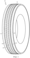
FIG. 1 is a front perspective view of a tire of the present invention; -
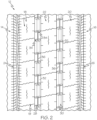
FIG. 2 is a front view of a portion of the tread of the tire ofFIG. 1 ; -
FIG. 3 is a section view through a tie bar of the tire tread region; and -
FIG. 4 is a section view of the tie bar under load in the footprint. - With reference to
FIGS. 1 and2 , a first embodiment of atire 10 of the present invention is provided having a circumferentiallycontinuous tread region 12. Thetread 12 preferably includes acenter rib 22, a first andsecond shoulder rib center rib 22, and a first and secondintermediate rib center rib 22. An equatorial center plane divides thetread 12 into two, preferably symmetrical halves. A pair of circumferentially continuousintermediate grooves center rib 22 and a respective intermediate rib. A pair of circumferentiallycontinuous shoulder grooves intermediate ribs shoulder ribs - Situated within at least one of said
grooves intermediate grooves bar elements 32 circumferentially spaced apart from each other around the circumference of thetire 10. - Each of the
tie bar elements 32 preferably has a generally quadrilateral shape with an elongate dimension in a circumferential direction. It is bounded along longitudinal sides of the respectivetie bar element 32 byadjacent ribs tread 12 and along transverse sides byend walls 34 of the respectivetie bar element 32. - The two
end walls 34 of eachtie bar element 32 are preferably angled and are more preferably angled in a direction away from each other when moving from the radiallyoutermost surface 39 of the respectivetie bar element 32 radially inwards. The angles theend walls 34 of thetie bar elements 32 make on each side with respect to the radial direction of the tire are preferably in a range of from +/-3 to +/-30 degrees, more preferably +/-5 to +/-20 degrees. - The tie-
bar elements 32 are spaced apart by a circumferential spacing lying within a preferred range of from 15 mm to 90 mm or from 15 to 45 mm. - As best shown in
Fig. 3 , each tie-bar element 32 has opposedsidewalls adjacent ribs - The
opposed sidewalls tie bar groove 36. Thetie bar groove 36 has a radially upper oroutermost portion 37 which is preferably the axially narrowest width portion of thetie bar groove 36. The radiallyupper portion 37 is or starts at the radially outer surface of thetie bar element 32 and radially close to thetread surface 58. - The
tie bar groove 36 tapers laterally outward when moving radially inward thus increasing in axial thickness from a narrow portion to a wider, radiallylower portion 40. Preferably, the increase in axial thickness from theupper portion 37 to thelower portion 40 is linear or about linear. The radial distance from theupper portion 37 to thelower portion 40 is preferably in a range of from 5 to 10 mm. - Moving from the radially
lower portion 40 further radially inwards, theopposed sidewalls circular bottom portion 42. The constant width apart preferably extends over a radial distance in a range of from 1 to 3 mm. - The hemi
circular bottom portion 42 preferably has an axial width in a range of from 2 mm to 4 mm, and preferably lies at the base of the tie-bar element 32. - A
tie bar channel 4 extends circumferentially through one or more of the tie-bar elements 32, preferably through each of thetie bar elements 32, and provides a conduit for snow and rain management. It is preferably dimensioned such that it remains open during operation of thetire 10 under the load the tire is designed for (rolling through the footprint). - As will be noted from
FIG. 2 , the tie-bar opposedsidewalls outermost tread surface 58. Thus, in the new condition, theupper surface 37 of each tie-bar element 32 does not constitute a part of the rolling tire footprint. After some wear of thetread 12 has occurred, thesurface 39 of eachblock element 32 is exposed and becomes part of the rolling tire footprint. Alternatively, if desired, the tie-bar elements 32 may also be constructed as the same height as theouter tread surface 58 when thetire 10 is new or unworn. - The maximum axial width of the
intermediate grooves - The maximum axial width of
tie bar groove 36 in theupper portion 37 is preferably within a range of 0.5 mm to 1.5 mm. This width is preferably selected such that the tie-bar opposed sidewalls 33, 35 engage each other and thereby close during operation of thetire 10 under the load the tire is designed for (rolling through the footprint) while thetie bar channel 4 remains open. - It will be appreciated that the
intermediate grooves outward tread surface 58 and have a maximum groove depth lying within a preferred range of from 12 mm to 18 mm. The tie-bar elements 32 are preferably radially recessed within a respectiveintermediate groove - The disclosed tread configuration reduces shoulder wear and irregular wear due to the rib width within a five-rib design. The
center rib 22 and theintermediate ribs wider shoulder ribs tread 12 is increased. - The described arrays of tie-
bar elements 32 within the grooves, preferably theintermediate grooves tread 12 more rigid and help to increase the cornering stiffness and also enhance better snow and wet performance through the tire life. The tie-bar elements 32 also stiffen thetread 12 for better cornering and mileage performance. The tie-bar elements 32, recessed withinrespective grooves tire 10 is new but establish contact after the tire tread wears. When the tie-bar elements 32 come into contact with road surface, theedges 34 at theopposed walls tire 10. Thetie bar channel 4 of each tie-bar element 32 constitutes an air and water conduit for directing air and water through thetie bar elements 32. - Allowing air to pass through the
tie bar elements 32 eliminates trapped air and thereby reduces the noise level of thetread 12. Also, by allowing the passage of water through thetie bar channels 4, aquaplaning is eliminated or reduced. - In the five rib construction of the
tread region 12, the net-to-gross ratio defined as net contact area (area enclosing the pattern of the tire tread in contact with a flat surface excluding the area of grooves or other voids at a definite load and inflation) to gross contact area (area enclosing the pattern of the tire tread in contact with a flat surface including the area of grooves or other voids at a definite load and inflation) is increased. The addition of the tie-bar elements 32 increases the lateral stiffness of the tread without impacting the circumferential stiffness of the tread. - When the tie-
bar element 32 enters the footprint of the rolling tire, thetie bar groove 36 closes in the axial direction, bringing theopposed sidewalls upper portion 37 of the tie-bar elements 32 together in touching relationship. As a result, the lateral stiffness of thetread 12 within the footprint is increased when the tie-bar element 32 is within the footprint, whereby cornering stiffness is enhanced, and frictional energy reduced. - When a tie-
bar element 32 leaves the footprint of the rolling tire, the tie-bar element 32 separates in the axial direction and thegroove 36 is reopened to its original width. The tie-bar elements 32 thus help improve mileage performance of thetire 12 by enhancing stiffness and reducing treadwear from lateral loads on the tread. The wider shoulder rib configuration further reduces the shoulder wear phenomena. As thetread 12 wears through use, the tie-bar elements 32 become road contacting elements and theedges bar elements 32 define additional contacting edges for enhanced traction. - The one or more array of tie-
bar elements 32 accordingly do not obstruct the functional performance of thegroove tie bar elements 32 are situated, and fluid such as rain or snow melt is able to traverse thecircumferential groove 36 unobstructed by the array of tie-bar elements 32. Thetire tread 12 thereby provides high mileage and durability desired by the user.
Claims (15)
- A tire comprising a tire tread (12) comprising a first and second rib (18, 22), wherein the first and second ribs (18, 22) are separated by a tread groove (28) and wherein at least one tie-bar element (32) is disposed within the tread groove (28), the tie-bar element (32) having opposed sidewalls (33, 35) separated by a radially extending tie bar groove (36), wherein the radially extending tie bar groove (36) tapers from a first axial width to a second width, the second width being wider than the first width, when moving radially inwards in the tie bar groove (36).
- The tire of claim 1, wherein the tie bar groove (32) has a radially lower portion wherein the opposed sidewalls (33, 35) are spaced apart at a constant width.
- The tire of claim 1 or 2, wherein the tie bar element (32) has a recessed upper surface (39) relative to an upper surface (58) of the tread (12).
- The tire of at least one of the previous claims, wherein there is a plurality of discrete tie-bar elements (32) disposed within the tread groove (28) with circumferentially adjacent tie-bar elements (32) being separated by a circumferential spacing, the circumferential spacing being preferably within a range of from 15 mm to 90 mm or from 15 to 45 mm.
- The tire of at least one of the previous claims, wherein the tie bar groove (32) includes a radially lower tie bar channel (4).
- The tire of claim 5, wherein the radially lower tie bar channel (4) is configured such that is remains open during operation of the tire (10) under a load the tire (10) is designed for.
- The tire of at least one of the previous claims, wherein the tread (12) includes a center rib (22), a first and second shoulder rib (14, 16) disposed on each side of the center rib (22), a first and second intermediate rib (18, 20) disposed on opposite sides of the center rib (22), and pair of circumferentially continuous intermediate grooves (28, 30) that are located between the center rib (22) and a respective intermediate rib (18, 20), and, optionally, wherein the tread (12) further comprises a pair of circumferentially continuous shoulder grooves (24, 26) which separate respectively, the intermediate ribs (18, 20) from the shoulder ribs (14, 16).
- The tire of at least one of the previous claims, wherein a plurality of discrete said tie-bar elements (32) are circumferentially spaced apart from each other around the circumference of the tire (10) and wherein said tie-bar elements (32) are located within one or more of said grooves (28, 30, 24, 26), preferably at least or only within one or both of the intermediate grooves (28, 30).
- The tire of at least one of the previous claims, wherein the tie bar elements (32) have a generally quadrilateral shape with an elongate dimension in a circumferential direction and wherein the tie bar elements (32) are bounded along longitudinal sides of the respective tie bar element (32) by adjacent ribs (18, 20, 22) of the tread (12) and along transverse sides by end walls (34) of the respective tie bar element 32, the end walls (34) being preferably angled.
- The tire of at least one of the previous claims, wherein the tie bar groove (36) has a radially upper or outermost portion (37) which is preferably the axially narrowest width portion of the tie bar groove (36), wherein the tie bar groove (36) tapers laterally outward when moving radially inward thus increasing in axial thickness to an axially wider, radially lower portion (40) and wherein, when moving from the radially lower portion (40) further radially inwards, the opposed sidewalls (33, 35) have a constant width apart and preferably terminate in a generally rounded, circular or hemi circular bottom portion (42).
- The tire of at least one of the previous claims, wherein the constant width apart extends over a radial distance in a range of from 1 to 3 mm; and/or wherein the bottom portion (42) has an axial width in a range of from 2 mm to 4 mm and preferably lies at the radially innermost base of the tie-bar element (32).
- The tire of at least one of the previous claims, wherein the maximum axial width of tie bar groove (36) in the upper portion (37) is within a range of 0.5 mm to 1.5 mm or is such that the tie-bar opposed sidewalls (33, 35) engage each other and thereby close during operation of the tire (10) under the load the tire (10) is designed for while the tie bar channel (4) remains open.
- The tire of at least one of the previous claims, wherein the center rib (22) and the intermediate ribs (18, 20) have a width in a range of from 50 to 80 percent of the relatively wider shoulder ribs (14, 16), the shoulder ribs (14, 16) preferably having an axial width within a range of from 40 mm to 60 mm.
- The tire of at least one of the previous claims, wherein the tire (10) is a truck tire.
- The tire of at least one of the previous claims, wherein the tire (10) is a truck steer tire.
Applications Claiming Priority (1)
| Application Number | Priority Date | Filing Date | Title |
|---|---|---|---|
| US18/319,710 US20240383286A1 (en) | 2023-05-18 | 2023-05-18 | Commercial truck tire |
Publications (3)
| Publication Number | Publication Date |
|---|---|
| EP4464522A2 true EP4464522A2 (en) | 2024-11-20 |
| EP4464522A3 EP4464522A3 (en) | 2024-12-11 |
| EP4464522B1 EP4464522B1 (en) | 2025-11-12 |
Family
ID=91067064
Family Applications (1)
| Application Number | Title | Priority Date | Filing Date |
|---|---|---|---|
| EP24174793.0A Active EP4464522B1 (en) | 2023-05-18 | 2024-05-08 | Truck tire |
Country Status (3)
| Country | Link |
|---|---|
| US (1) | US20240383286A1 (en) |
| EP (1) | EP4464522B1 (en) |
| CN (1) | CN118991302A (en) |
Family Cites Families (8)
| Publication number | Priority date | Publication date | Assignee | Title |
|---|---|---|---|---|
| JPS54136002A (en) * | 1978-04-08 | 1979-10-22 | Bridgestone Corp | Pneumatic radial tire for heavy car running on good highway at high speed |
| JPH10250317A (en) * | 1997-03-13 | 1998-09-22 | Bridgestone Corp | Heavy duty pneumatic tire |
| JP4873514B2 (en) * | 2001-01-29 | 2012-02-08 | 東洋ゴム工業株式会社 | Pneumatic tire |
| KR20060058922A (en) * | 2004-11-26 | 2006-06-01 | 한국타이어 주식회사 | Heavy duty tires |
| FR2940185B1 (en) * | 2008-12-22 | 2010-12-17 | Michelin Soc Tech | ROLLER BAND WITH IMPROVED DRAINAGE VOLUME |
| US9186935B2 (en) * | 2011-09-13 | 2015-11-17 | The Goodyear Tire & Rubber Company | Commercial truck steer tire tread |
| FR3049899A1 (en) * | 2016-04-08 | 2017-10-13 | Michelin & Cie | TIRE TREAD FOR TIRES |
| KR102683153B1 (en) * | 2022-07-07 | 2024-07-10 | 금호타이어 주식회사 | Pneumatic tire tread with protruding shape structure in grooves |
-
2023
- 2023-05-18 US US18/319,710 patent/US20240383286A1/en active Pending
-
2024
- 2024-05-08 EP EP24174793.0A patent/EP4464522B1/en active Active
- 2024-05-17 CN CN202410616453.0A patent/CN118991302A/en active Pending
Also Published As
| Publication number | Publication date |
|---|---|
| EP4464522B1 (en) | 2025-11-12 |
| EP4464522A3 (en) | 2024-12-11 |
| CN118991302A (en) | 2024-11-22 |
| US20240383286A1 (en) | 2024-11-21 |
Similar Documents
| Publication | Publication Date | Title |
|---|---|---|
| EP2570272B1 (en) | Tire tread | |
| AU2009230798B2 (en) | Pneumatic tire with asymmetric tread pattern | |
| EP1935671B1 (en) | Pneumatic tire | |
| AU2006201886B2 (en) | Pneumatic tire | |
| US8813800B2 (en) | Pneumatic tire | |
| RU2427476C1 (en) | Pneumatic tire | |
| EP2432652B1 (en) | Tyre for a motor vehicle | |
| EP2570271B1 (en) | High mileage tire tread | |
| EP2163405A1 (en) | Pneumatic tire | |
| US11001103B2 (en) | Tread for a tire | |
| CN101588934B (en) | pneumatic tire | |
| US6439284B1 (en) | Tread for a pneumatic tire including aquachannel | |
| EP1935670B1 (en) | Pneumatic tire | |
| EP3017964A1 (en) | An improved tread for a snow tire | |
| EP3995324B1 (en) | Tire with one or more recesses in the lateral grooves of at least one shoulder portion | |
| JP4268034B2 (en) | Pneumatic tire | |
| JP4800610B2 (en) | Pneumatic radial tire | |
| JP4404398B2 (en) | Pneumatic tire | |
| US20030111151A1 (en) | Pneumatic tire | |
| JP4595503B2 (en) | Pneumatic tire | |
| EP3332990A1 (en) | Tire tread for a snow tire | |
| EP4464522A2 (en) | Truck tire | |
| JP4285617B2 (en) | Pneumatic radial tire | |
| EP1021306B1 (en) | Tread for a pneumatic tire | |
| JP2000309206A (en) | Pneumatic tire |
Legal Events
| Date | Code | Title | Description |
|---|---|---|---|
| PUAI | Public reference made under article 153(3) epc to a published international application that has entered the european phase |
Free format text: ORIGINAL CODE: 0009012 |
|
| STAA | Information on the status of an ep patent application or granted ep patent |
Free format text: STATUS: THE APPLICATION HAS BEEN PUBLISHED |
|
| PUAL | Search report despatched |
Free format text: ORIGINAL CODE: 0009013 |
|
| AK | Designated contracting states |
Kind code of ref document: A2 Designated state(s): AL AT BE BG CH CY CZ DE DK EE ES FI FR GB GR HR HU IE IS IT LI LT LU LV MC ME MK MT NL NO PL PT RO RS SE SI SK SM TR |
|
| AK | Designated contracting states |
Kind code of ref document: A3 Designated state(s): AL AT BE BG CH CY CZ DE DK EE ES FI FR GB GR HR HU IE IS IT LI LT LU LV MC ME MK MT NL NO PL PT RO RS SE SI SK SM TR |
|
| RIC1 | Information provided on ipc code assigned before grant |
Ipc: B60C 11/13 20060101ALI20241106BHEP Ipc: B60C 11/12 20060101ALI20241106BHEP Ipc: B60C 11/04 20060101AFI20241106BHEP |
|
| STAA | Information on the status of an ep patent application or granted ep patent |
Free format text: STATUS: REQUEST FOR EXAMINATION WAS MADE |
|
| 17P | Request for examination filed |
Effective date: 20250429 |
|
| GRAP | Despatch of communication of intention to grant a patent |
Free format text: ORIGINAL CODE: EPIDOSNIGR1 |
|
| STAA | Information on the status of an ep patent application or granted ep patent |
Free format text: STATUS: GRANT OF PATENT IS INTENDED |
|
| INTG | Intention to grant announced |
Effective date: 20250613 |
|
| GRAS | Grant fee paid |
Free format text: ORIGINAL CODE: EPIDOSNIGR3 |
|
| GRAA | (expected) grant |
Free format text: ORIGINAL CODE: 0009210 |
|
| STAA | Information on the status of an ep patent application or granted ep patent |
Free format text: STATUS: THE PATENT HAS BEEN GRANTED |
|
| AK | Designated contracting states |
Kind code of ref document: B1 Designated state(s): AL AT BE BG CH CY CZ DE DK EE ES FI FR GB GR HR HU IE IS IT LI LT LU LV MC ME MK MT NL NO PL PT RO RS SE SI SK SM TR |
|
| REG | Reference to a national code |
Ref country code: CH Ref legal event code: F10 Free format text: ST27 STATUS EVENT CODE: U-0-0-F10-F00 (AS PROVIDED BY THE NATIONAL OFFICE) Effective date: 20251112 Ref country code: GB Ref legal event code: FG4D |
|
| REG | Reference to a national code |
Ref country code: DE Ref legal event code: R096 Ref document number: 602024001233 Country of ref document: DE |
|
| REG | Reference to a national code |
Ref country code: IE Ref legal event code: FG4D |
|
| REG | Reference to a national code |
Ref country code: NL Ref legal event code: MP Effective date: 20251112 |
|
| PG25 | Lapsed in a contracting state [announced via postgrant information from national office to epo] |
Ref country code: ES Free format text: LAPSE BECAUSE OF FAILURE TO SUBMIT A TRANSLATION OF THE DESCRIPTION OR TO PAY THE FEE WITHIN THE PRESCRIBED TIME-LIMIT Effective date: 20251112 |
|
| REG | Reference to a national code |
Ref country code: LT Ref legal event code: MG9D |
|
| PG25 | Lapsed in a contracting state [announced via postgrant information from national office to epo] |
Ref country code: NO Free format text: LAPSE BECAUSE OF FAILURE TO SUBMIT A TRANSLATION OF THE DESCRIPTION OR TO PAY THE FEE WITHIN THE PRESCRIBED TIME-LIMIT Effective date: 20260212 |
|
| PG25 | Lapsed in a contracting state [announced via postgrant information from national office to epo] |
Ref country code: FI Free format text: LAPSE BECAUSE OF FAILURE TO SUBMIT A TRANSLATION OF THE DESCRIPTION OR TO PAY THE FEE WITHIN THE PRESCRIBED TIME-LIMIT Effective date: 20251112 Ref country code: HR Free format text: LAPSE BECAUSE OF FAILURE TO SUBMIT A TRANSLATION OF THE DESCRIPTION OR TO PAY THE FEE WITHIN THE PRESCRIBED TIME-LIMIT Effective date: 20251112 Ref country code: AT Free format text: LAPSE BECAUSE OF FAILURE TO SUBMIT A TRANSLATION OF THE DESCRIPTION OR TO PAY THE FEE WITHIN THE PRESCRIBED TIME-LIMIT Effective date: 20251112 |
|
| REG | Reference to a national code |
Ref country code: AT Ref legal event code: MK05 Ref document number: 1856450 Country of ref document: AT Kind code of ref document: T Effective date: 20251112 |
|
| PG25 | Lapsed in a contracting state [announced via postgrant information from national office to epo] |
Ref country code: NL Free format text: LAPSE BECAUSE OF FAILURE TO SUBMIT A TRANSLATION OF THE DESCRIPTION OR TO PAY THE FEE WITHIN THE PRESCRIBED TIME-LIMIT Effective date: 20251112 |
|
| PG25 | Lapsed in a contracting state [announced via postgrant information from national office to epo] |
Ref country code: RS Free format text: LAPSE BECAUSE OF FAILURE TO SUBMIT A TRANSLATION OF THE DESCRIPTION OR TO PAY THE FEE WITHIN THE PRESCRIBED TIME-LIMIT Effective date: 20260212 |
|
| PG25 | Lapsed in a contracting state [announced via postgrant information from national office to epo] |
Ref country code: IS Free format text: LAPSE BECAUSE OF FAILURE TO SUBMIT A TRANSLATION OF THE DESCRIPTION OR TO PAY THE FEE WITHIN THE PRESCRIBED TIME-LIMIT Effective date: 20260312 |
|
| PG25 | Lapsed in a contracting state [announced via postgrant information from national office to epo] |
Ref country code: PT Free format text: LAPSE BECAUSE OF FAILURE TO SUBMIT A TRANSLATION OF THE DESCRIPTION OR TO PAY THE FEE WITHIN THE PRESCRIBED TIME-LIMIT Effective date: 20260312 |
|
| PG25 | Lapsed in a contracting state [announced via postgrant information from national office to epo] |
Ref country code: PL Free format text: LAPSE BECAUSE OF FAILURE TO SUBMIT A TRANSLATION OF THE DESCRIPTION OR TO PAY THE FEE WITHIN THE PRESCRIBED TIME-LIMIT Effective date: 20251112 |
|
| PG25 | Lapsed in a contracting state [announced via postgrant information from national office to epo] |
Ref country code: LV Free format text: LAPSE BECAUSE OF FAILURE TO SUBMIT A TRANSLATION OF THE DESCRIPTION OR TO PAY THE FEE WITHIN THE PRESCRIBED TIME-LIMIT Effective date: 20251112 |