EP4464517A1 - Anti-counterfeiting labels with solid-state fluorescent carbon nanodots - Google Patents
Anti-counterfeiting labels with solid-state fluorescent carbon nanodots Download PDFInfo
- Publication number
- EP4464517A1 EP4464517A1 EP23173768.5A EP23173768A EP4464517A1 EP 4464517 A1 EP4464517 A1 EP 4464517A1 EP 23173768 A EP23173768 A EP 23173768A EP 4464517 A1 EP4464517 A1 EP 4464517A1
- Authority
- EP
- European Patent Office
- Prior art keywords
- laser
- donor material
- acceptor
- precursor
- fluorescent carbon
- Prior art date
- Legal status (The legal status is an assumption and is not a legal conclusion. Google has not performed a legal analysis and makes no representation as to the accuracy of the status listed.)
- Withdrawn
Links
Images




Classifications
-
- B—PERFORMING OPERATIONS; TRANSPORTING
- B42—BOOKBINDING; ALBUMS; FILES; SPECIAL PRINTED MATTER
- B42D—BOOKS; BOOK COVERS; LOOSE LEAVES; PRINTED MATTER CHARACTERISED BY IDENTIFICATION OR SECURITY FEATURES; PRINTED MATTER OF SPECIAL FORMAT OR STYLE NOT OTHERWISE PROVIDED FOR; DEVICES FOR USE THEREWITH AND NOT OTHERWISE PROVIDED FOR; MOVABLE-STRIP WRITING OR READING APPARATUS
- B42D25/00—Information-bearing cards or sheet-like structures characterised by identification or security features; Manufacture thereof
- B42D25/40—Manufacture
- B42D25/45—Associating two or more layers
-
- B—PERFORMING OPERATIONS; TRANSPORTING
- B41—PRINTING; LINING MACHINES; TYPEWRITERS; STAMPS
- B41M—PRINTING, DUPLICATING, MARKING, OR COPYING PROCESSES; COLOUR PRINTING
- B41M3/00—Printing processes to produce particular kinds of printed work, e.g. patterns
- B41M3/14—Security printing
-
- B—PERFORMING OPERATIONS; TRANSPORTING
- B42—BOOKBINDING; ALBUMS; FILES; SPECIAL PRINTED MATTER
- B42D—BOOKS; BOOK COVERS; LOOSE LEAVES; PRINTED MATTER CHARACTERISED BY IDENTIFICATION OR SECURITY FEATURES; PRINTED MATTER OF SPECIAL FORMAT OR STYLE NOT OTHERWISE PROVIDED FOR; DEVICES FOR USE THEREWITH AND NOT OTHERWISE PROVIDED FOR; MOVABLE-STRIP WRITING OR READING APPARATUS
- B42D25/00—Information-bearing cards or sheet-like structures characterised by identification or security features; Manufacture thereof
- B42D25/30—Identification or security features, e.g. for preventing forgery
- B42D25/36—Identification or security features, e.g. for preventing forgery comprising special materials
-
- B—PERFORMING OPERATIONS; TRANSPORTING
- B42—BOOKBINDING; ALBUMS; FILES; SPECIAL PRINTED MATTER
- B42D—BOOKS; BOOK COVERS; LOOSE LEAVES; PRINTED MATTER CHARACTERISED BY IDENTIFICATION OR SECURITY FEATURES; PRINTED MATTER OF SPECIAL FORMAT OR STYLE NOT OTHERWISE PROVIDED FOR; DEVICES FOR USE THEREWITH AND NOT OTHERWISE PROVIDED FOR; MOVABLE-STRIP WRITING OR READING APPARATUS
- B42D25/00—Information-bearing cards or sheet-like structures characterised by identification or security features; Manufacture thereof
- B42D25/30—Identification or security features, e.g. for preventing forgery
- B42D25/36—Identification or security features, e.g. for preventing forgery comprising special materials
- B42D25/378—Special inks
- B42D25/387—Special inks absorbing or reflecting ultraviolet light
-
- B—PERFORMING OPERATIONS; TRANSPORTING
- B42—BOOKBINDING; ALBUMS; FILES; SPECIAL PRINTED MATTER
- B42D—BOOKS; BOOK COVERS; LOOSE LEAVES; PRINTED MATTER CHARACTERISED BY IDENTIFICATION OR SECURITY FEATURES; PRINTED MATTER OF SPECIAL FORMAT OR STYLE NOT OTHERWISE PROVIDED FOR; DEVICES FOR USE THEREWITH AND NOT OTHERWISE PROVIDED FOR; MOVABLE-STRIP WRITING OR READING APPARATUS
- B42D25/00—Information-bearing cards or sheet-like structures characterised by identification or security features; Manufacture thereof
- B42D25/40—Manufacture
- B42D25/405—Marking
- B42D25/41—Marking using electromagnetic radiation
-
- G—PHYSICS
- G07—CHECKING-DEVICES
- G07D—HANDLING OF COINS OR VALUABLE PAPERS, e.g. TESTING, SORTING BY DENOMINATIONS, COUNTING, DISPENSING, CHANGING OR DEPOSITING
- G07D7/00—Testing specially adapted to determine the identity or genuineness of valuable papers or for segregating those which are unacceptable, e.g. banknotes that are alien to a currency
- G07D7/06—Testing specially adapted to determine the identity or genuineness of valuable papers or for segregating those which are unacceptable, e.g. banknotes that are alien to a currency using wave or particle radiation
- G07D7/12—Visible light, infrared or ultraviolet radiation
- G07D7/1205—Testing spectral properties
-
- G—PHYSICS
- G07—CHECKING-DEVICES
- G07D—HANDLING OF COINS OR VALUABLE PAPERS, e.g. TESTING, SORTING BY DENOMINATIONS, COUNTING, DISPENSING, CHANGING OR DEPOSITING
- G07D7/00—Testing specially adapted to determine the identity or genuineness of valuable papers or for segregating those which are unacceptable, e.g. banknotes that are alien to a currency
- G07D7/20—Testing patterns thereon
- G07D7/202—Testing patterns thereon using pattern matching
- G07D7/2033—Matching unique patterns, i.e. patterns that are unique to each individual paper
-
- G—PHYSICS
- G07—CHECKING-DEVICES
- G07D—HANDLING OF COINS OR VALUABLE PAPERS, e.g. TESTING, SORTING BY DENOMINATIONS, COUNTING, DISPENSING, CHANGING OR DEPOSITING
- G07D7/00—Testing specially adapted to determine the identity or genuineness of valuable papers or for segregating those which are unacceptable, e.g. banknotes that are alien to a currency
- G07D7/20—Testing patterns thereon
- G07D7/202—Testing patterns thereon using pattern matching
- G07D7/205—Matching spectral properties
Definitions
- the invention relates to the field of anti-counterfeiting labels with solid-state fluorescent carbon nanodots.
- Anti-counterfeiting is a serious global problem, causing trillion-dollar losses to industry.
- Anti-counterfeiting methods include unclonable fluorescent labels with unique patterns in a variety of industries such as pharmaceuticals, certificates, and electronics.
- a considerable number of fluorescent materials have been explored for this purpose, including semiconductor quantum dots, organic dyes, and carbon dots.
- carbon dots stand out in particular because of their stability, low toxicity, widely available precursors, and bio-/eco-friendly preparation.
- CDs carbon dots
- most reported CDs only fluoresce in solution, while suffering from ⁇ - ⁇ stacking and quenching in the solid-state.
- a method for producing an anti-counterfeiting label comprising a laser printing method, comprising: providing a donor material, the donor material comprising a precursor on a first side of the donor material, wherein the precursor is a carbon-based chemical compound; providing an acceptor material, wherein an acceptor side of the acceptor material is arranged adjacent to the first side of the donor material; annealing the precursor by a laser, wherein the laser is controlled with laser parameters adjusted to convert the precursor to solid-state fluorescent carbon nanodots; and removing the donor material to receive the solid-state fluorescent carbon nanodot-based anti-counterfeiting label on the acceptor side of the acceptor material.
- the presented method may enable the production of solid-state emissive fluorescent carbon nanodot anti-counterfeiting labels.
- solid-state emissive may describe the process in which a chemical compound in its solid form may have fluorescent properties, e.g., under a UV light or any other kind of light source.
- one advantage of the method may be to provide an unclonable fluorescent carbon nanodot pattern as a physical unclonable function, where the term unclonable may describe that the fluorescent pattern generated by the presented method may not be copied either exactly and/or similarly with the same or any other method.
- the term physical unclonable function may describe that the solid-state fluorescent carbon nanodot anti-counterfeiting label may provide a physically defined unique identifier.
- the unclonable feature may be provided the complexity of the structure of the fluorescent pattern.
- the method may be relying on carbon dot patterns with solid-state fluorescence.
- Carbon nanodot patterns may comprise fluorescent carbon nanodots, which may be a type of fluorescent material comprising carbon atoms and/or fluorescent carbon-based molecules.
- the carbon dot patterns may have other properties, such as including but not limited to a high stability and low toxicity, as well as long-lasting fluorescent properties that may not decay after a short period of time.
- it may be produced from widely available precursors, and may be prepared in a bio-/eco-friendly fashion.
- the synthesis and patterning of the solid-state fluorescent carbon nanodots may be carried out within a single, eco-friendly, and cost-efficient step.
- the presented method may be ultrafast and may be carried out within milliseconds.
- the carbon nanodots may be generated in situ and solid-state fluorescent carbon dots with a thickness e.g. in the nanometer range and a unique, unclonable microstructure may be achieved.
- in-situ may describe that the solid-state fluorescent carbon nanodots may be synthesized at the exact same location as and from the precursor.
- a microstructure may describe the distribution of the solid-state fluorescent carbon nanodots in the vertical and horizontal plane on the acceptor side of the acceptor material.
- the solid-state fluorescent carbon nanodots may lead to the solid-state fluorescent carbon nanodots being transferred from the first side of the donor material to the acceptor side of the acceptor material.
- the precursor may be partially or fully be converted to solid-state fluorescent carbon nanodots.
- the solid-state fluorescent carbon nanodots may comprise a portion of the precursor material.
- a solid-state fluorescent carbon nanodot microstructure that may serve as an anti-counterfeiting label with the abovementioned properties may be received on the acceptor side of the acceptor material.
- the solid-state fluorescent carbon nanodot microstructure may comprise a portion of the precursor material.
- the donor material further comprises at least one laser-absorbing layer or material and/or at least one auxiliary material on the first side of the donor material, wherein the at least one auxiliary material is selected from a list of polyethylene glycol, polyvinyl alcohol, dicyandiamide, polyvinylpyrrolidone, citric acid, MgSO4, Na2SO4, Urea, HBO3, HCl, KCI.
- the laser-absorbing layer may be a compound that absorbs light that may be emitted from a laser and convert that light into heat.
- the precursor may be a compound comprising carbon atoms, and the heat that may be generated by the laser-absorbing layer may be used for annealing the carbon-containing precursor so that the precursor is converted to solid-state fluorescent carbon nanodots.
- the precursor may be spin coated onto the donor material and may be a compound that may be capable of forming solid-state fluorescent carbon nanodots after being heated up to a certain temperature.
- the laser-absorbing layer may be carbon nanoparticles.
- the laser-absorbing material may be mixed with the precursor. For example, this combination of the precursor and the laser-absorbing material may serve as a combined layer that may be transferred to the acceptor material.
- the precursor itself may serve the function as the laser-absorbing layer and no additional laser-absorbing material may be added.
- adding an auxiliary material to the first side of the donor material may influence certain properties of the solid-state fluorescent carbon nanodots, the solid-state fluorescent carbon nanodot microstructure and the anti-counterfeiting label.
- Those properties may be e.g., the fluorescent wavelength of the solid-state fluorescent carbon nanodots, the randomness of the spatial carbon nanodots distribution on the acceptor side, the carbon nanodots topographic distribution, i.e., the height maps and height profiles, on the acceptor side, the shape, size, position, and orientation of the solid-state fluorescent carbon nanodot droplets, the density of the solid-state fluorescent carbon nanodot microstructure, the fluorescence intensity, and the decay time of the fluorescence.
- a solid-state fluorescent carbon nanodot droplet may be an agglomerate of multiple solid-state fluorescent carbon nanodots of a certain shape, size, and orientation.
- auxiliary materials By adding one or more of auxiliary materials, the above-mentioned properties may be altered in a way that an anti-counterfeiting label with desired properties may be produced by the presented method.
- the method may further comprise: selecting a production parameter set from a library, the library associating multiple production parameter sets with corresponding fluorescent carbon nanodot properties, the production parameter sets comprising one or more of the following production parameters: chemical properties of the donor material, chemical properties of the acceptor material, chemical properties of the auxiliary material, laser parameters.
- the fluorescent carbon nanodot properties may comprise the properties from the previous example.
- the production parameters may be altered in a way that an anti-counterfeiting label with desired properties may be produced by the presented laser printing method.
- the library may serve as a convenient way to associate multiple production parameter sets with the corresponding fluorescent carbon nanodot properties.
- the library may be able to e.g., provide the necessary production parameters for the presented solid-state fluorescent carbon nanodot production method.
- the laser parameters are comprising at least one of the following: laser power, laser scanning speed, printing mode, wherein the laser scanning speed describes a movement speed of the laser over the donor material, wherein the printing mode comprises either a continuous scanning of laser over the donor material or a scanning of the laser over the donor material with discrete spatial laser illumination points with different delay times in between lasing.
- the laser parameters may also influence the solid-state fluorescent carbon nanodot properties during the production process.
- the fluorescent carbon nanodot properties are comprising at least anyone of: a randomness of nanodots distribution, a measure of nanodots topographic distribution, an average fluorescent wavelength, a fluorescence intensity, a fluorescence lifetime, a Raman spectrum, an infrared (IR) spectrum.
- the measure of nanodots topographic distribution may comprise the thickness and the height profile of the solid-state carbon nanodot pattern/microstructure on the acceptor side of the acceptor material.
- the thickness of the solid-state carbon nanodot pattern/microstructure may not be uniform, when the solid-state fluorescent carbon nanodot droplets have e.g., a particle-like or a stripe-like droplet pattern, but somewhat uniform when the solid-state fluorescent carbon nanodots form a continuous carbon nanodot pattern with random defects.
- the average fluorescent wavelength may determine the fluorescent color of the solid-state fluorescent carbon nanodots when for example, the solid-state fluorescent carbon nanodots are excited with e.g., UV light. It may be any color indivisible or invisible spectrum of the light, wherein examples include but are not limited to a red color, a blue color, a green color, a yellow color, a purple color, an orange color, an infrared color, or an ultraviolet color.
- the measure of nanodots topographic distribution are determined using white light interferometry.
- white light interferometry is a non-contact optical method to measure the surface height of 3D structures.
- the annealing of the precursor by the laser is comprising directing the laser to a second side of the donor material, the second side being opposite to the first side.
- the laser-absorbing layer is comprising any one of the following: Fe 2 O 3 , CuO, silicone, glass, aluminum, paper, polyethylene terephthalate, polyimide, graphite.
- the precursor is comprising an absorber.
- the absorber is e.g., black carbon nanoparticles.
- the donor material and the acceptor material are glass or are based on glass.
- the carbon-based chemical compound is or is based on toluenesulfonic acid or saccharide.
- the saccharide is at least one or a combination of the following: glucose, glucosamine, galactose, N-acetylglucosamine.
- the first side of the donor material and the acceptor side of the acceptor material are arranged in immediate contact to each other.
- an immediate contact between these two materials may decrease the transfer distance for the carbon nanodots.
- a close or immediate contact between the first side of the donor material and the acceptor side of the acceptor material may maximize the amount of solid-state fluorescent carbon nanodots that is transferred from the donor material to the acceptor material.
- Immediate contact may be understood as a contact between the donor material and the acceptor material, which besides a possible unevenness of the donor or acceptor material or its respective carriers are physically placed on top of each other.
- An example of immediate contact is the contact of two glass surfaces each carrying the donor and the acceptor material.
- the method may further comprise providing the library comprising assigning a multitude of different production parameter sets to corresponding fluorescent carbon nanodot properties, wherein the respective properties are measured from carbon nanodots as generated using the laser printing method with the respective production parameter set.
- the library may be populated using experimentally generated solid-state fluorescent carbon nanodot anti-counterfeiting labels and their respective fluorescent carbon nanodot properties as well as the correlated production parameters.
- the library may serve as an experimentally generated library, where anti-counterfeiting labels that were previously generated using the presented method and their respective production parameters may be looked up.
- This may enable the production of future anti-counterfeiting labels with equivalent fluorescent carbon nanodot properties as those anti-counterfeiting labels stored in the library and may provide a possibility for a look up of the production parameter sets and the corresponding fluorescent carbon nanodot properties in the library.
- the library may comprise a trained machine learning model configured for receiving the fluorescent carbon nanodot properties as input, process the input and provide the production parameter set as output, the method comprising receiving the input for execution by the machine learning model and providing the output by the machine learning model.
- a machine learning approach may be that it is possible to produce a large amount of solid-state fluorescent carbon nanodot anti-counterfeiting labels with different (desired) properties without the need of having prior trial-and error experiments to prove that all these kinds of labels can readily be produced using the laser printing method, which is both time and cost-efficient.
- the usage of the trained machine learning model may complement the library described in the previous example.
- the method may further comprise providing a training dataset and executing a learning algorithm on the training set for generating the machine learning model, the training dataset comprising a multitude of different production parameter sets associated with corresponding fluorescent carbon nanodot properties, wherein the respective properties are corresponding to carbon nanodots as experimentally generated using the laser printing method with the respective production parameter set.
- the machine learning model may be trained using the library that is populated with the experimentally generated and/or predicted solid-state fluorescent carbon nanodot anti-counterfeiting labels.
- An example comprises the usage of a laser printing method for the production of anti-counterfeiting labels, wherein the laser printing method comprises: providing a donor material, the donor material comprising a laser-absorbing layer and a precursor on a first side of the donor material, wherein the precursor is a carbon-based chemical compound; providing an acceptor material, wherein an acceptor side of the acceptor material is arranged adjacent to the first side of the donor material; annealing the precursor by a laser, wherein the laser is controlled with laser parameters adjusted to convert the precursor to solid-state fluorescent carbon nanodots; and removing the donor material to receive the solid-state fluorescent carbon nanodot-based anti-counterfeiting label on the acceptor side of the acceptor material.
- an anti-counterfeiting label is disclosed, wherein the anti-counterfeiting label is obtainable by the method of any of the previous examples.
- a method for authenticating the anti-counterfeiting label of the previous examples comprising: obtaining, from the anti-counterfeiting label, an authentication pattern using white light interferometry and fluorescence; accessing a database, the database comprising valid authentication patterns of valid anti-counterfeiting labels; comparing the generated authentication pattern with the valid authentication patterns; and report the result of the comparison.
- the method for authenticating may comprise a lookup if the obtained authentication pattern may be stored in the database.
- the obtained authentication pattern may comprise a primary key, such as including but not limited to a name, a code, and/or a serial number.
- the method for authenticating may comprise a lookup if the primary key comprises the obtained pattern within a database.
- Figure 1 shows a laser printer 100, comprising a laser 108, a donor material 102, and an acceptor material 112.
- the donor material 102 comprises a laser-absorbing layer 104, and furthermore, in a 2 nd layer, a precursor 106 that may or may not be mixed with one or more optional auxiliary materials 114.
- the donor material 102, the laser-absorbing layer 104 and the layer comprising the precursor 106 and any auxiliary material 114 form the donor slide 110.
- the donor material 102 is then annealed in an air oven at e.g. 500 °C for 3 h. After cooling down, the final hematite layer is obtained.
- the donor material 102 is a glass slide.
- the donor material 102 can also be any other suitable material that can be used in conjunction with a laser and within an anti-counterfeiting label printing process.
- CuO copper oxide
- PVA polyvinyl alcohol
- D-(+)-glucose can be replaced with D-(+)-Glucosamine hydrochloride, D-Galactose, or N-Acetylglucosamine.
- the precursor 106 layer on the donor material 102 and the laser-absorbing layer 104 can further comprise one or more auxiliary materials 114.
- the auxiliary material can be one or more of the following materials: polyethylene glycol, polyvinyl alcohol, dicyandiamide, polyvinylpyrrolidone, citric acid, MgSO 4 , Na 2 SO 4 , Urea, HBO 3 , HCl, KCI.
- the auxiliary material 114 can furthermore be any other water-soluble chemical compound.
- the one or more auxiliary materials 114 are added to the precursor 104 solution before the spin-coating and, if added, is comprised by the same layer as the precursor 104.
- the donor material 102 is then cleaned on one side so that the laser-absorbing layer 104 and the layer comprising the precursor 106 and any auxiliary material 114 are only present on a first side of the donor material 102. Together, the laser-absorbing layer 104, the precursor 106, and any optional auxiliary material 114 on the first side of the donor material 102 form the donor slide 110.
- the donor slide 110 is then placed on top of a clean acceptor material 112.
- the acceptor material 112 is a glass slide.
- the acceptor material 112 can also be any other suitable material that can be used in conjunction with a laser and within an anti-counterfeiting label printing process, e.g., aluminum, paper, copper etc.
- the donor slide 110 and the acceptor material 112 are in immediate contact to each other. They are placed directly on top of each other, with the first side of the donor material 102 facing one side of the acceptor material 112.
- the layer comprising the precursor 106 and any auxiliary material 114 is in direct contact to the acceptor material 112, wherein direct contact means that the minimum physical distance between the two objects is achieved.
- a laser 108 is placed on a second side, opposed to the first side of the donor material 102.
- the laser beam is directed towards the donor material 102.
- the laser 108 is a 200 mW 488 nm laser with a 1:10 beam expander, but it may be any other suitable laser.
- Flowchart 200 describes a method for producing an anti-counterfeiting label utilizing solid-state fluorescent carbon nanodots, using the laser printer 100.
- the donor material 102 is provided in the first step 202.
- it is then prepared, as described above, with the laser-absorbing layer 104, the precursor 106, and any potential auxiliary material 114 on the first side of the donor material 102 to receive the donor slide 110.
- step 206 the acceptor material 112 is placed in immediate contact to the donor slide 110.
- step 208 the printing process of the anti-counterfeiting label starts.
- the laser 108 is scanned over the donor material 102 onto the laser-absorbing layer 104, which then absorbs the laser beam and heats up to a certain temperature, e.g., above 500 °C, which in terms anneals the precursor 106.
- Laser parameters that can be changed when controlling the laser are the laser power, the laser scanning speed, and the laser printing mode, wherein the laser scanning speeds describes the movement speed of the laser over the donor material 102.
- the laser printing mode can either be the laser performing a continuous scanning over the donor material 102 and the laser-absorbing layer 104 or performing a scanning over the donor material 102 and the laser-absorbing layer 104 with discrete spatial laser illumination points.
- the heating of the laser-absorbing layer 104 and the annealing of the precursor 106 leads to 1) the formation of solid-state fluorescent carbon nanodots from the precursor and (as some potential transfer mechanisms) 2) e.g., thermal surface expansion and/or partial evaporation, and/or ablation, and/or burning of the newly formed solid-state fluorescent carbon nanodots.
- the material (solid-state fluorescent carbon nanodots) underlying the fluorescent anti-counterfeiting label is generated.
- the solid-state fluorescent carbon nanodots are transferred from the donor material 102 to the acceptor material 112.
- transfer mechanisms are conceivable. As both the donor material 102 and the acceptor material 112 are in direct contact to each other, the distance that the solid-state present carbon nanodots have to move from the donor material 102 to the acceptor material 112 is minimal.
- the precursor 106 which in this example is D-(+)-glucose but can be any other sugar
- a ring-opening of the chemical molecule occurs in some parts of the precursor 106, and HCl as a molecule is eliminated.
- the resulting chemical compound then oligomerizes by intermolecular dehydration and as a result, forms solid-state fluorescent carbon nanodots.
- the donor slide 110 is then removed from the acceptor material 112, and the acceptor material 112 then comprises a solid-state fluorescent carbon nanodot structure on an acceptor side as anti-counterfeiting label.
- the acceptor side is the side that was placed directly adjacent to the first side of the donor material 102.
- the solid-state fluorescent carbon nanodot structure has a unique random pattern which properties are directly dependent on the choice of the laser-absorbing layer 104, the precursor 106, the optional auxiliary materials 114, and the laser parameters.
- Figure 3 depicts two exemplary and experimentally obtained topographic profiles of different carbon nanodot structures that were generated using different laser parameters.
- the topographic profiles were characterized by white light interferometry and extracted by edge detection, which is the method of identifying edges in a digital image.
- the left column depicts the readouts from the white light interferometry
- the right column depicts the results from the edge detection.
- Row 302 was generated with a laser power of 49 mW and a laser scanning speed of 120 mm/s
- row 304 was generated with a laser power of 49 mW and a laser scanning speed of 130 mm/s.
- the figure 3 further demonstrates the effects of different laser parameters on the shape, size, position, and orientation of the solid-state fluorescent carbon nanodots and the density of the solid-state fluorescent carbon nanodot structure.
- Row 302 of figure 3 shows particle-like droplets
- row 304 shows stripe-like droplets.
- the stripe-like droplets have a higher thickness between 100-150 nm than particle-like droplets (30-80 nm) or a continuous carbon nanodot film (80-95 nm), while the continuous carbon nanodot film is not shown in figure 3 .
- the donor and acceptor material are glass
- the chemical properties of the auxiliary material include that polyvinyl alcohol are added as an auxiliary material 114
- the precursor 106 is N-acetylglucosamine
- the laser is printing in a continuous scanning mode over the donor material.
- the addition of polyvinyl alcohol as an auxiliary material 114 enhances the red fluorescence of the solid-state fluorescent carbon nanodots.
- the equivalent radius distribution of the particle-like droplets follows a Gaussian distribution with a Kolmogorov-Smirnov p-value of 0.007. This indicates that the equivalent radius of the particle-like droplets is not uniform but rather close to normally distributed.
- This non-uniform distribution of the droplet size, i.e., their equivalent radius enables the solid-state fluorescent carbon nanodot structure to serve as an unclonable anti-counterfeiting label with a unique structure.
- the structure further provides a strong physical unclonable function, wherein the term physical unclonable function describes that the solid-state fluorescent carbon nanodot anti-counterfeiting label provides a physically defined unique identifier.
- the calculated texture-aspect ratio of the stripe-like droplets is 0.566.
- the texture-aspect ratio is a measure of uniformity of the surface texture, which may have a value between 0 and 1, wherein zero defines a uniform surface pattern and one defines a completely random surface pattern.
- the calculated value of 0.566 is much higher than a reference value of 0.3 taken from the DIN ISO 25178 standard relating to the analysis of 3D areal surface texture.
- the calculated texture-aspect ratio of the stripe-like droplets suggests a high randomness of the droplet angular orientation. In this example, the high randomness enables the solid-state fluorescent carbon nanodot structure to serve as an unclonable anti-counterfeiting label with a unique structure, providing a physical unclonable function.
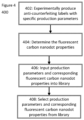
- the flowchart 400 depicts a process of generating a library comprising experimentally produced solid-state fluorescent carbon nanodot anti-counterfeiting labels.
- multiple anti-counterfeiting labels with a solid-state fluorescent carbon nanodot structure are produced experimentally.
- multiple specific production parameters are chosen.
- the production parameters comprise different chemical the properties of the donor material, different chemical properties of the acceptor material, different chemical properties of the optional auxiliary material, and different laser parameters.
- the fluorescent carbon nanodot properties comprise parameters such as e.g., solid-state fluorescent carbon nanodot droplet angular orientation, size, position, shape, density, equivalent radius, fluorescent color, fluorescent intensity.
- step 406 the production parameters and the corresponding fluorescent carbon nanodot properties are stored in the library.
- step 408 the desired fluorescent carbon nanodot properties and the corresponding production parameters are selected from the library e.g., in the manner of a look-up procedure in order to reproduce the desired fluorescent carbon nanodot properties during another production run using the method 200 of figure 2 .
- Figure 5 shows a set of experimentally generated solid-state fluorescent carbon nanodot labels 500 that may form the basis for the library as discussed above.
- Figure 5 depicts 1920 different solid-state fluorescent carbon nanodot labels, each produced with particular production parameters.
- the solid-state fluorescent carbon nanodot labels were generated using the method 200 of figure 2 .
- Each solid-state fluorescent carbon nanodot label has different carbon nanodot properties and the respective corresponding production parameters.
- the experimentally generated solid-state fluorescent carbon nanodot label can be used to train a machine learning module.
- the trained machine learning model is then able to predict both solid-state fluorescent carbon nanodot production parameter and the corresponding carbon nanodot properties.
- the machine learning module for use with the solid-state fluorescent carbon nanodot library 500 may be trained using the extreme gradient boosting (XGB) algorithm to predict a multitude of solid-state fluorescent carbon nanodot labels.
- Other models for training are e.g., random forest regression (RF).
- the trained model may be provided and being queried on the fly by requesting respective production parameters based on desired carbon nanodot properties. Since this may be time and computer resource consuming, in another example a multitude of carbon nanodot labels may be predicted by the model based on a predefined or randomly selected extended set of desired nanodot properties and provided as readily available library.
- the library comprising the predicted solid-state fluorescent carbon nanodot films may also be used in other use cases, for example in bioimaging, security, photocatalysis, sensors, or optoelectronic devices.
- Flowchart 600 of figure 6 depicts a method to authorize the anti-counterfeiting label that is produced using the method of the process 200 of figure 2 .
- fluorescence measurements and white light interferometry measurement are used to receive 2 authentication keys, key F (fluorescence) and key W (white light interferometry).
- the white light interferometry provides basically for a height profile distribution of the carbon nanodots of the label.
- the authentication keys comprise the readout data from both measurements.
- step 604 a valid key F (fluorescence) and key W (white light interferometry) solid-state fluorescent carbon nanodot pattern data is obtained from a database.
- step 606 the valid patterns of step 604 are compared to the obtained pattern of step 602 using e.g., a LoFTR (Detector-Free Local Feature Matching with Transformers) algorithm.
- the algorithm carries out similarity analysis and correlation calculation between the valid and the obtained patterns.
- the algorithm performs a direct comparison of the obtained key F and key W pattern with a valid pattern stored in the database.
- the obtained key F and key W may comprise another primary key, such as including but not limited to a name, a code, and/or a serial number.
- the method for authenticating may comprise a lookup if the primary key comprises the obtained pattern within a database.
- step 608 the results of the comparison are reported.
- FIG. 1 Unlike the traditional strategies, where CDs are synthesized and purified in a liquid phase, and then optimized for SSF, it is aimed to synthesize CDs directly in the solid phase by a solvent-free approach. It is aimed to prepare films from the precursor D-(+)-glucosamine hydrochloride on glass slides and heated them in an air oven. Significant fluorescence occurred in the water solution of the annealed films and higher annealing temperatures caused a redshift of the fluorescence. Nuclear magnetic resonance spectroscopy (NMR) and liquid chromatography-mass spectrometry indicated that this solvent-free synthesis possibly shared the same mechanism with the reported liquid-phase synthesis from the same precursors.
- NMR nuclear magnetic resonance spectroscopy
- FIG. 1 nuclear magnetic resonance spectroscopy
- Laser-based nanoprinting technologies can precisely heat a confined position in milliseconds. After introducing a nanolayer laser absorber, it is highly improved the resolution of the nanoprinting technology.
- film-forming precursors e.g., monosaccharides
- it is aimed to now leave out the supporting polymer matrix during ink preparation which is mandatory for printing.
- it is aimed to develop a nanoprinting-assisted flash (nanoFlash) synthesis approach, achieving in-situ SSF during the ultrafast printing of micro/nanopatterns.
- the monosaccharide solution was spin-coated onto a glass slide with a laser-absorber layer.
- the absorber layer converted the laser pulses into heat, achieving a temperature above 500 °C.
- the precursor was melted and transferred onto another substrate.
- the thickness of the transferred patterns was tunable in the nanoscale.
- the ultrafast annealing process avoided overheating and the formation of large carbon flakes on the printed film. Without any post-treatment, SSF was observed in the directly transferred pattern.
- the fluorescence signal from the red (635 nm), green (532 nm), and blue (488 nm) channels (RGB channels) showed a clear response to the change of laser parameters.
- the nanoFlash synthesis approach offers extremely fast scanning speeds of up to hundreds of mm s-1.
- Scanning electron microscopy revealed that distinct microstructures appeared on the transferred areas and their structures could be tuned by the laser intensity. Notably, it is aimed to place the obtained patterns under UV light (285 nm) for up to 15 h, without observing fluorescence quenching.
- a thin protection layer may be introduced on top of the patterns by spin coating, making them waterproof.
- the obtained thin films from the nanoFlash approach were in-situ analyzed by X-ray photoelectron (XPS) spectroscopy.
- XPS X-ray photoelectron
- the PCDs formed in the process are more likely polymeric fluorescent molecules. When dissolved in water and dried on another surface, they aggregated into nanoparticles.
- the 3D fluorescence spectra revealed an excitation-dependent behavior of the nanofilms, similar to the case of matrix dispersed SSF.
- the PCDs are likely dispersed in the precursor matrix, which strongly reduces Förster resonance energy transfer to avoid aggregation-induced fluorescence quenching in the solid state.
- the fluorescence spectra of the films obtained with different parameters were also investigated. With increasing excitation wavelengths, the fluorescence intensity ratio between the two samples is reversed, resulting in different observed colors. Since the highly flexible nanoFlash synthesis enables multiple tunable parameters, a library with thousands of 1 mm 2 nanofilms, exhibiting fluorescent colors from violet-blue to red, was established. To quantitatively reveal the connection between their performance and synthesis conditions, it is aimed to introduce machine learning and the SHAP (SHapley Additive exPlanations) descriptor to the library. Seven different models (e.g. random forest regression (RF), and extreme gradient boosting (XGB)) were trained, and three common property criteria, (e.g.
- RF random forest regression
- XGB extreme gradient boosting
- the SHAP summary plot gives details on how the fluorescence output depends on different parameters. Based on the ranking of SHAP values, the donor absorber was recognized as the most important feature for the fluorescence intensity in all three channels. Besides, the effect of different additives on the fluorescence intensity is also clearly listed. For example, the addition of polyvinyl alcohol (PVA) gave enhanced red fluorescence, while the addition of polyethylene glycol (PEG) was detrimental.
- PVA polyvinyl alcohol
- PEG polyethylene glycol
- nanofilms with similar fluorescent colors have distinct micropatterns (e.g., particle-like droplets, stripe-like droplets, continuous films with random defects).
- the shape and density of these microstructures directly influence the security level and encoding capacity of the anti-counterfeiting patterns, offering more possibilities for practical applications.
- the height maps and profiles of the nanofilms show that stripe-like droplets have a higher thickness between 100-150 nm than particle-like droplets (30-80 nm), or continuous films (80-95 nm).
- the equivalent radius distribution of the extracted particle-like droplets follows a random Gaussian distribution with a Kolmogorov-Smirnov p-value of 0.007. Droplet orientations were detected and characterized by the autocorrelation function.
- the edges (150 ⁇ m) of the patterns were cut off, resulting in 325 x 325 pixels for each PUF pattern. Since it is aimed to have two independent readout methods (FL and WLI), the theoretical encoding capacity could reach about 1063593, satisfying the typical criterion for a strong PUF device. From the authentication results, it is aimed to derive the false authentication and authentication error functions. At decision thresholds of 0.27 and 0.41 for FL and WLI respectively, the probability of HD-based false authentication provides an estimate for the probability of cloning of a pattern of below 10-93 and 10-18. Next, the open-source algorithm LoFTR (Detector-Free Local Feature Matching with Transformers) was adopted for the authentication process.
- LoFTR Detector-Free Local Feature Matching with Transformers
- Combining the nanoFlash process with a defined macroscopic pattern can add extra encryption for anti-counterfeiting labels.
- the macro-pattern has been designed to selectively show or hide specific information under different readout methods. It is aimed to plant PUF structures in an artificial fingerprint pattern to visualize the independent microstructures in the fluorescence and topography channels.
- the synthesis parameters for the fluorescent fingerprint patterns were derived from the library and high color reproducibility was observed.
- the height maps of the fingerprints could serve as an additional PUF feature to the fluorescence microstructures, making the patterns immune to attacks like nanomolding. Another scanning after two months revealed that the nano-thickness maps remained unchanged, suggesting high stability.
- Restricting the nanoFlash process to a defined macro-pattern does not change the micro-/nanoscopic nature and general properties of PUF structures. However, it could cause a potential bias during authentication, since the defined macropattern is much easier to be recognized by algorithms in comparison to the microstructures. It is aimed to analyze the inter- and intracorrelation of different fingerprint patterns, which were scanned directly or after 2 two months. Even though the intracorrelation is sometimes lower than those from the simple square PUF patterns, the distinct difference between the intra- and intercorrelation makes it sufficient for a reliable authentication process.
- Table 1 shows PUF parameters for fluorescence and topography characterization. Calculated values are the average with standard deviation, integrated values are the average with error propagation.
Landscapes
- Physics & Mathematics (AREA)
- Engineering & Computer Science (AREA)
- General Physics & Mathematics (AREA)
- Health & Medical Sciences (AREA)
- General Health & Medical Sciences (AREA)
- Toxicology (AREA)
- Computer Vision & Pattern Recognition (AREA)
- Spectroscopy & Molecular Physics (AREA)
- Manufacturing & Machinery (AREA)
- Electromagnetism (AREA)
- Carbon And Carbon Compounds (AREA)
Abstract
Disclosed is a method for producing an anti-counterfeiting label, the method comprising a laser printing method comprising: providing a donor material (102), the donor material (102) comprising a precursor (106) on a first side of the donor material (102), wherein the precursor (106) is a carbon-based chemical compound; providing an acceptor material (112), wherein an acceptor side of the acceptor material (112) is arranged adjacent to the first side of the donor material (102); annealing the precursor (106) by a laser (108), wherein the laser (108) is controlled with laser parameters adjusted to convert the precursor (106) to solid-state fluorescent carbon nanodots; and removing the donor material (102) to receive the solid-state fluorescent carbon nanodot-based anti-counterfeiting label on the acceptor side of the acceptor material (112).
Description
- The invention relates to the field of anti-counterfeiting labels with solid-state fluorescent carbon nanodots.
- Counterfeiting is a serious global problem, causing trillion-dollar losses to industry. Anti-counterfeiting methods include unclonable fluorescent labels with unique patterns in a variety of industries such as pharmaceuticals, certificates, and electronics. A considerable number of fluorescent materials have been explored for this purpose, including semiconductor quantum dots, organic dyes, and carbon dots. Among these materials, carbon dots (CDs) stand out in particular because of their stability, low toxicity, widely available precursors, and bio-/eco-friendly preparation. However, most reported CDs only fluoresce in solution, while suffering from π-π stacking and quenching in the solid-state.
- Encryption by physical unclonable functions, such as identifiable macropatterns with unpredictable microstructure, provide a facile solution to make optical security devices easy to verify but challenging to forge. Physical unclonable functions are fabricated by stochastic processes to guarantee uniquely random patterns. For anti-counterfeiting labeling, physical unclonable functions are typically generated by rough surfaces or discrete nanoparticle arrays within a predefined area. Even though they show high security levels, physical unclonable function patterns always require either tedious fabrication or complex readout methods, which hamper their practical application. Herein, we propose an all-in-one nanoprinting approach to in-situ generate carbon dot nanofilms with multichannel unclonable microstructures.
- It is an objective to provide for a method for producing an improved anti-counterfeiting label, a respective production method for the production of anti-counterfeiting labels, a respective anti-counterfeiting label and the use of a such produced anti-counterfeiting label for authentication purposes. The objectives underlying the invention are solved by the features of the independent claims.
- In one aspect, a method for producing an anti-counterfeiting label is disclosed, the method comprising a laser printing method, comprising: providing a donor material, the donor material comprising a precursor on a first side of the donor material, wherein the precursor is a carbon-based chemical compound; providing an acceptor material, wherein an acceptor side of the acceptor material is arranged adjacent to the first side of the donor material; annealing the precursor by a laser, wherein the laser is controlled with laser parameters adjusted to convert the precursor to solid-state fluorescent carbon nanodots; and removing the donor material to receive the solid-state fluorescent carbon nanodot-based anti-counterfeiting label on the acceptor side of the acceptor material.
- In an example, the presented method may enable the production of solid-state emissive fluorescent carbon nanodot anti-counterfeiting labels. In this example, solid-state emissive may describe the process in which a chemical compound in its solid form may have fluorescent properties, e.g., under a UV light or any other kind of light source. In another example, one advantage of the method may be to provide an unclonable fluorescent carbon nanodot pattern as a physical unclonable function, where the term unclonable may describe that the fluorescent pattern generated by the presented method may not be copied either exactly and/or similarly with the same or any other method. The term physical unclonable function may describe that the solid-state fluorescent carbon nanodot anti-counterfeiting label may provide a physically defined unique identifier. In another example, the unclonable feature may be provided the complexity of the structure of the fluorescent pattern. In another example, the method may be relying on carbon dot patterns with solid-state fluorescence. Carbon nanodot patterns may comprise fluorescent carbon nanodots, which may be a type of fluorescent material comprising carbon atoms and/or fluorescent carbon-based molecules. In addition to the solid-state emissive fluorescence, the carbon dot patterns may have other properties, such as including but not limited to a high stability and low toxicity, as well as long-lasting fluorescent properties that may not decay after a short period of time. In another example, it may be produced from widely available precursors, and may be prepared in a bio-/eco-friendly fashion.
- In an example, the synthesis and patterning of the solid-state fluorescent carbon nanodots may be carried out within a single, eco-friendly, and cost-efficient step. In comparison to other nanoprinting techniques which may take days, the presented method may be ultrafast and may be carried out within milliseconds. Using the presented method, the carbon nanodots may be generated in situ and solid-state fluorescent carbon dots with a thickness e.g. in the nanometer range and a unique, unclonable microstructure may be achieved. In an example, in-situ may describe that the solid-state fluorescent carbon nanodots may be synthesized at the exact same location as and from the precursor. In another example, a microstructure may describe the distribution of the solid-state fluorescent carbon nanodots in the vertical and horizontal plane on the acceptor side of the acceptor material.
- For example, during the annealing of the precursor material and the forming of the solid-state fluorescent carbon nanodots, e.g., thermal surface expansion and/or partial evaporation, and/or ablation, and/or burning of the carbon precursor and/or solid-state fluorescent carbon nanodots may lead to the solid-state fluorescent carbon nanodots being transferred from the first side of the donor material to the acceptor side of the acceptor material. In an example, the precursor may be partially or fully be converted to solid-state fluorescent carbon nanodots. In another example, the solid-state fluorescent carbon nanodots may comprise a portion of the precursor material.
- For example, after removing the donor material, a solid-state fluorescent carbon nanodot microstructure that may serve as an anti-counterfeiting label with the abovementioned properties may be received on the acceptor side of the acceptor material. In an example, the solid-state fluorescent carbon nanodot microstructure may comprise a portion of the precursor material.
- In an example, the donor material further comprises at least one laser-absorbing layer or material and/or at least one auxiliary material on the first side of the donor material, wherein the at least one auxiliary material is selected from a list of polyethylene glycol, polyvinyl alcohol, dicyandiamide, polyvinylpyrrolidone, citric acid, MgSO4, Na2SO4, Urea, HBO3, HCl, KCI.
- For example, the laser-absorbing layer may be a compound that absorbs light that may be emitted from a laser and convert that light into heat. In another example, the precursor may be a compound comprising carbon atoms, and the heat that may be generated by the laser-absorbing layer may be used for annealing the carbon-containing precursor so that the precursor is converted to solid-state fluorescent carbon nanodots. In an example, the precursor may be spin coated onto the donor material and may be a compound that may be capable of forming solid-state fluorescent carbon nanodots after being heated up to a certain temperature. In an example, the laser-absorbing layer may be carbon nanoparticles. In another example, the laser-absorbing material may be mixed with the precursor. For example, this combination of the precursor and the laser-absorbing material may serve as a combined layer that may be transferred to the acceptor material. In another example, the precursor itself may serve the function as the laser-absorbing layer and no additional laser-absorbing material may be added.
- In an example, adding an auxiliary material to the first side of the donor material may influence certain properties of the solid-state fluorescent carbon nanodots, the solid-state fluorescent carbon nanodot microstructure and the anti-counterfeiting label. Those properties may be e.g., the fluorescent wavelength of the solid-state fluorescent carbon nanodots, the randomness of the spatial carbon nanodots distribution on the acceptor side, the carbon nanodots topographic distribution, i.e., the height maps and height profiles, on the acceptor side, the shape, size, position, and orientation of the solid-state fluorescent carbon nanodot droplets, the density of the solid-state fluorescent carbon nanodot microstructure, the fluorescence intensity, and the decay time of the fluorescence. In an example, a solid-state fluorescent carbon nanodot droplet may be an agglomerate of multiple solid-state fluorescent carbon nanodots of a certain shape, size, and orientation. By adding one or more of auxiliary materials, the above-mentioned properties may be altered in a way that an anti-counterfeiting label with desired properties may be produced by the presented method.
- In an example, the method may further comprise: selecting a production parameter set from a library, the library associating multiple production parameter sets with corresponding fluorescent carbon nanodot properties, the production parameter sets comprising one or more of the following production parameters: chemical properties of the donor material, chemical properties of the acceptor material, chemical properties of the auxiliary material, laser parameters. The fluorescent carbon nanodot properties may comprise the properties from the previous example. In the present example, the production parameters may be altered in a way that an anti-counterfeiting label with desired properties may be produced by the presented laser printing method. In an example, the library may serve as a convenient way to associate multiple production parameter sets with the corresponding fluorescent carbon nanodot properties. In one example, there may be a need to receive solid-state fluorescent carbon nanodot droplets with a distinct pattern, e.g., particle-like droplets, stripe-like droplets, or a continuous carbon nanodot film with random defects. There may also be a requirement for e.g., a specific thickness of the fluorescent carbon nanodot patterns or the fluorescent carbon nanodots droplets, or e.g., a requirement for the droplets to have certain equivalent radius distribution. In order to achieve specific fluorescent carbon nanodot properties, the library may be able to e.g., provide the necessary production parameters for the presented solid-state fluorescent carbon nanodot production method.
- For example, the chemical properties are comprising at least one of: chemical compositions, chemical concentrations. In an example, by altering the chemical composition and/or the concentration of the donor material, acceptor material, or the auxiliary material, different solid-state fluorescent carbon nanodot properties may be achieved. For example, different chemical compositions and/or chemical concentrations of said materials may be associated with the specific solid-state fluorescent carbon nanodot properties in the library.
- For example, the laser parameters are comprising at least one of the following: laser power, laser scanning speed, printing mode, wherein the laser scanning speed describes a movement speed of the laser over the donor material, wherein the printing mode comprises either a continuous scanning of laser over the donor material or a scanning of the laser over the donor material with discrete spatial laser illumination points with different delay times in between lasing. For example, the laser parameters may also influence the solid-state fluorescent carbon nanodot properties during the production process.
- For example, the fluorescent carbon nanodot properties are comprising at least anyone of: a randomness of nanodots distribution, a measure of nanodots topographic distribution, an average fluorescent wavelength, a fluorescence intensity, a fluorescence lifetime, a Raman spectrum, an infrared (IR) spectrum.
- In an example, the randomness of nanodots distribution may comprise several properties of the solid-state fluorescent carbon nanodots and/or the solid-state fluorescent carbon nanodot microstructure. In one example, the randomness of nanodots distribution may comprise the equivalent radius distribution of the fluorescent carbon nanodots droplets. In another example, the randomness of nanodots distribution may include but is not limited to the solid-state fluorescent carbon nanodot droplet angular orientation, the droplet position, and the droplet size.
- In an example, the measure of nanodots topographic distribution may comprise the thickness and the height profile of the solid-state carbon nanodot pattern/microstructure on the acceptor side of the acceptor material. In an example, the thickness of the solid-state carbon nanodot pattern/microstructure may not be uniform, when the solid-state fluorescent carbon nanodot droplets have e.g., a particle-like or a stripe-like droplet pattern, but somewhat uniform when the solid-state fluorescent carbon nanodots form a continuous carbon nanodot pattern with random defects.
- In an example, the average fluorescent wavelength may determine the fluorescent color of the solid-state fluorescent carbon nanodots when for example, the solid-state fluorescent carbon nanodots are excited with e.g., UV light. It may be any color indivisible or invisible spectrum of the light, wherein examples include but are not limited to a red color, a blue color, a green color, a yellow color, a purple color, an orange color, an infrared color, or an ultraviolet color.
- For example, the measure of nanodots topographic distribution are determined using white light interferometry. In an example, white light interferometry is a non-contact optical method to measure the surface height of 3D structures.
- For example, the annealing of the precursor by the laser is comprising directing the laser to a second side of the donor material, the second side being opposite to the first side.
- In an example, the laser-absorbing layer is comprising any one of the following: Fe2O3, CuO, silicone, glass, aluminum, paper, polyethylene terephthalate, polyimide, graphite. In another example, the precursor is comprising an absorber. In an example, the absorber is e.g., black carbon nanoparticles.
- In an example, a laser wavelength that may be directly absorbed by the precursor is used. For example, this laser wavelength is e.g., an infrared (IR) laser. In an example, the IR laser is used in combination with an IR permissive donor material. In an example, the IR permissive donor material is e.g., silicone.
- In an example, the donor material and the acceptor material are glass or are based on glass.
- In an example, the carbon-based chemical compound is or is based on toluenesulfonic acid or saccharide. In another example, the saccharide is at least one or a combination of the following: glucose, glucosamine, galactose, N-acetylglucosamine.
- For example, the first side of the donor material and the acceptor side of the acceptor material are arranged in immediate contact to each other. For example, as the transfer of the solid-state fluorescent carbon nanodots from the donor material to the acceptor material may be caused by e.g., thermal surface expansion and/or partial evaporation, ablation, and/or burning, an immediate contact between these two materials may decrease the transfer distance for the carbon nanodots. In an example, a close or immediate contact between the first side of the donor material and the acceptor side of the acceptor material may maximize the amount of solid-state fluorescent carbon nanodots that is transferred from the donor material to the acceptor material. Immediate contact may be understood as a contact between the donor material and the acceptor material, which besides a possible unevenness of the donor or acceptor material or its respective carriers are physically placed on top of each other. An example of immediate contact is the contact of two glass surfaces each carrying the donor and the acceptor material.
- In an example, the method may further comprise providing the library comprising assigning a multitude of different production parameter sets to corresponding fluorescent carbon nanodot properties, wherein the respective properties are measured from carbon nanodots as generated using the laser printing method with the respective production parameter set. For example, the library may be populated using experimentally generated solid-state fluorescent carbon nanodot anti-counterfeiting labels and their respective fluorescent carbon nanodot properties as well as the correlated production parameters. In this case, the library may serve as an experimentally generated library, where anti-counterfeiting labels that were previously generated using the presented method and their respective production parameters may be looked up. This may enable the production of future anti-counterfeiting labels with equivalent fluorescent carbon nanodot properties as those anti-counterfeiting labels stored in the library and may provide a possibility for a look up of the production parameter sets and the corresponding fluorescent carbon nanodot properties in the library.
- In an example, the library may comprise a trained machine learning model configured for receiving the fluorescent carbon nanodot properties as input, process the input and provide the production parameter set as output, the method comprising receiving the input for execution by the machine learning model and providing the output by the machine learning model. The benefit of such a machine learning approach may be that it is possible to produce a large amount of solid-state fluorescent carbon nanodot anti-counterfeiting labels with different (desired) properties without the need of having prior trial-and error experiments to prove that all these kinds of labels can readily be produced using the laser printing method, which is both time and cost-efficient. The usage of the trained machine learning model may complement the library described in the previous example.
- In an example, the method may further comprise providing a training dataset and executing a learning algorithm on the training set for generating the machine learning model, the training dataset comprising a multitude of different production parameter sets associated with corresponding fluorescent carbon nanodot properties, wherein the respective properties are corresponding to carbon nanodots as experimentally generated using the laser printing method with the respective production parameter set. For example, the machine learning model may be trained using the library that is populated with the experimentally generated and/or predicted solid-state fluorescent carbon nanodot anti-counterfeiting labels.
- An example comprises the usage of a laser printing method for the production of anti-counterfeiting labels, wherein the laser printing method comprises: providing a donor material, the donor material comprising a laser-absorbing layer and a precursor on a first side of the donor material, wherein the precursor is a carbon-based chemical compound; providing an acceptor material, wherein an acceptor side of the acceptor material is arranged adjacent to the first side of the donor material; annealing the precursor by a laser, wherein the laser is controlled with laser parameters adjusted to convert the precursor to solid-state fluorescent carbon nanodots; and removing the donor material to receive the solid-state fluorescent carbon nanodot-based anti-counterfeiting label on the acceptor side of the acceptor material.
- In another aspect, an anti-counterfeiting label is disclosed, wherein the anti-counterfeiting label is obtainable by the method of any of the previous examples.
- In another aspect, a method for authenticating the anti-counterfeiting label of the previous examples is disclosed, the method comprising: obtaining, from the anti-counterfeiting label, an authentication pattern using white light interferometry and fluorescence; accessing a database, the database comprising valid authentication patterns of valid anti-counterfeiting labels; comparing the generated authentication pattern with the valid authentication patterns; and report the result of the comparison. In one example, the method for authenticating may comprise a lookup if the obtained authentication pattern may be stored in the database. In another example, the obtained authentication pattern may comprise a primary key, such as including but not limited to a name, a code, and/or a serial number. In that example, the method for authenticating may comprise a lookup if the primary key comprises the obtained pattern within a database.
- It is understood that one or more of the aforementioned examples may be combined as long as the combined examples are not mutually exclusive.
- In the following, examples are described in greater detail making reference to the drawings in which:
-
Fig. 1 is a schematic of a laser printing setup. -
Fig. 2 is a method to laser-print an anti-counterfeiting label. -
Fig. 3 are topographic profiles of different carbon nanodot structures. -
Fig. 4 is a method of generating a library comprising experimentally produced solid-state fluorescent carbon nanodot anti-counterfeiting labels. -
Fig. 5 is a solid-state fluorescent carbon nanodot library. -
Fig. 6 is a method to authorize an anti-counterfeiting label. - In the following, similar elements are denoted by the same reference numerals.
-
Figure 1 shows alaser printer 100, comprising alaser 108, adonor material 102, and anacceptor material 112. Thedonor material 102 comprises a laser-absorbinglayer 104, and furthermore, in a 2nd layer, aprecursor 106 that may or may not be mixed with one or more optionalauxiliary materials 114. Together, thedonor material 102, the laser-absorbinglayer 104 and the layer comprising theprecursor 106 and anyauxiliary material 114 form thedonor slide 110. - In the
figure 1 , the laser-absorbinglayer 104 is e.g., a hematite film that is prepared by e.g., preparing two solutions: 125 mg of PVA (polyvinyl alcohol, av. Mw=9000~10000) and 125 mg of Fe(NO3)3·9H2O in 250 µl of ddH2O (solution 1), and 250 mg of PEG (Polyethylene glycol, av. Mw ≈20 000) and 250 mg of Fe(NO3)3·9H2O in 250 µl of methanol (solution 2). Both solutions 1 and 2 are then mixed and then spin coated at 70 rounds per second on thedonor material 102. Thedonor material 102 is then annealed in an air oven at e.g. 500 °C for 3 h. After cooling down, the final hematite layer is obtained. In the present example, thedonor material 102 is a glass slide. However, thedonor material 102 can also be any other suitable material that can be used in conjunction with a laser and within an anti-counterfeiting label printing process. - Instead of using a hematite film, copper oxide (CuO) can be used as the laser-absorbing
layer 104, which is prepared by e.g., dissolving 0.175 g Cu(NO3)2·xH2O and 0.175 g PVA (polyvinyl alcohol, av. Mw=9000~10000) in 0.5 ml water and spin-coating the solution thedonor material 102 at 70 rounds per second. The slide is then annealed at e.g. 500 °C for 3 h in an air oven. After cooling down, the final CuO layer is obtained as a black film. - In the present example, the
precursor 106 is prepared by dissolving 25 mg D-(+)-glucose in 500 µL of water. The solution is then spin-coated onto the laser-absorbinglayer 104 at 70 rounds per second to obtain ahomogeneous precusor 106 as a layer. Instead of using 25 mg of D-(+)-glucose, 50 mg, 100 mg, or 150 mg, or any other suitable amount can also be used. - In a different example, the D-(+)-glucose can be replaced with D-(+)-Glucosamine hydrochloride, D-Galactose, or N-Acetylglucosamine.
- The
precursor 106 layer on thedonor material 102 and the laser-absorbinglayer 104 can further comprise one or moreauxiliary materials 114. The auxiliary material can be one or more of the following materials: polyethylene glycol, polyvinyl alcohol, dicyandiamide, polyvinylpyrrolidone, citric acid, MgSO4, Na2SO4, Urea, HBO3, HCl, KCI. Theauxiliary material 114 can furthermore be any other water-soluble chemical compound. The one or moreauxiliary materials 114 are added to theprecursor 104 solution before the spin-coating and, if added, is comprised by the same layer as theprecursor 104. - The
donor material 102 is then cleaned on one side so that the laser-absorbinglayer 104 and the layer comprising theprecursor 106 and anyauxiliary material 114 are only present on a first side of thedonor material 102. Together, the laser-absorbinglayer 104, theprecursor 106, and any optionalauxiliary material 114 on the first side of thedonor material 102 form thedonor slide 110. Thedonor slide 110 is then placed on top of aclean acceptor material 112. In the present example, theacceptor material 112 is a glass slide. However, theacceptor material 112 can also be any other suitable material that can be used in conjunction with a laser and within an anti-counterfeiting label printing process, e.g., aluminum, paper, copper etc. - In the present example, the
donor slide 110 and theacceptor material 112 are in immediate contact to each other. They are placed directly on top of each other, with the first side of thedonor material 102 facing one side of theacceptor material 112. Thus, the layer comprising theprecursor 106 and anyauxiliary material 114 is in direct contact to theacceptor material 112, wherein direct contact means that the minimum physical distance between the two objects is achieved. - On a second side, opposed to the first side of the
donor material 102, alaser 108 is placed. The laser beam is directed towards thedonor material 102. In the present example, thelaser 108 is a 200 mW 488 nm laser with a 1:10 beam expander, but it may be any other suitable laser. -
Flowchart 200 describes a method for producing an anti-counterfeiting label utilizing solid-state fluorescent carbon nanodots, using thelaser printer 100. In thefirst step 202, thedonor material 102 is provided. Instep 204, it is then prepared, as described above, with the laser-absorbinglayer 104, theprecursor 106, and any potentialauxiliary material 114 on the first side of thedonor material 102 to receive thedonor slide 110. - In
step 206, theacceptor material 112 is placed in immediate contact to thedonor slide 110. - In
step 208, the printing process of the anti-counterfeiting label starts. Thelaser 108 is scanned over thedonor material 102 onto the laser-absorbinglayer 104, which then absorbs the laser beam and heats up to a certain temperature, e.g., above 500 °C, which in terms anneals theprecursor 106. - Laser parameters that can be changed when controlling the laser are the laser power, the laser scanning speed, and the laser printing mode, wherein the laser scanning speeds describes the movement speed of the laser over the
donor material 102. The laser printing mode can either be the laser performing a continuous scanning over thedonor material 102 and the laser-absorbinglayer 104 or performing a scanning over thedonor material 102 and the laser-absorbinglayer 104 with discrete spatial laser illumination points. - The heating of the laser-absorbing
layer 104 and the annealing of theprecursor 106 leads to 1) the formation of solid-state fluorescent carbon nanodots from the precursor and (as some potential transfer mechanisms) 2) e.g., thermal surface expansion and/or partial evaporation, and/or ablation, and/or burning of the newly formed solid-state fluorescent carbon nanodots. In 1), the material (solid-state fluorescent carbon nanodots) underlying the fluorescent anti-counterfeiting label is generated. In 2), the solid-state fluorescent carbon nanodots are transferred from thedonor material 102 to theacceptor material 112. However, other transfer mechanisms are conceivable. As both thedonor material 102 and theacceptor material 112 are in direct contact to each other, the distance that the solid-state present carbon nanodots have to move from thedonor material 102 to theacceptor material 112 is minimal. - During the annealing of the
precursor 106, which in this example is D-(+)-glucose but can be any other sugar, a ring-opening of the chemical molecule occurs in some parts of theprecursor 106, and HCl as a molecule is eliminated. The resulting chemical compound then oligomerizes by intermolecular dehydration and as a result, forms solid-state fluorescent carbon nanodots. - In the
next step 210, thedonor slide 110 is then removed from theacceptor material 112, and theacceptor material 112 then comprises a solid-state fluorescent carbon nanodot structure on an acceptor side as anti-counterfeiting label. The acceptor side is the side that was placed directly adjacent to the first side of thedonor material 102. The solid-state fluorescent carbon nanodot structure has a unique random pattern which properties are directly dependent on the choice of the laser-absorbinglayer 104, theprecursor 106, the optionalauxiliary materials 114, and the laser parameters. -
Figure 3 depicts two exemplary and experimentally obtained topographic profiles of different carbon nanodot structures that were generated using different laser parameters. The topographic profiles were characterized by white light interferometry and extracted by edge detection, which is the method of identifying edges in a digital image. The left column depicts the readouts from the white light interferometry, the right column depicts the results from the edge detection. Row 302 was generated with a laser power of 49 mW and a laser scanning speed of 120 mm/s,row 304 was generated with a laser power of 49 mW and a laser scanning speed of 130 mm/s. Thefigure 3 further demonstrates the effects of different laser parameters on the shape, size, position, and orientation of the solid-state fluorescent carbon nanodots and the density of the solid-state fluorescent carbon nanodot structure. Row 302 offigure 3 shows particle-like droplets,row 304 shows stripe-like droplets. The stripe-like droplets have a higher thickness between 100-150 nm than particle-like droplets (30-80 nm) or a continuous carbon nanodot film (80-95 nm), while the continuous carbon nanodot film is not shown infigure 3 . - In this example, the donor and acceptor material are glass, the chemical properties of the auxiliary material include that polyvinyl alcohol are added as an
auxiliary material 114, theprecursor 106 is N-acetylglucosamine, and the laser is printing in a continuous scanning mode over the donor material. In this example, the addition of polyvinyl alcohol as anauxiliary material 114 enhances the red fluorescence of the solid-state fluorescent carbon nanodots. - In
row 302, the equivalent radius distribution of the particle-like droplets follows a Gaussian distribution with a Kolmogorov-Smirnov p-value of 0.007. This indicates that the equivalent radius of the particle-like droplets is not uniform but rather close to normally distributed. This non-uniform distribution of the droplet size, i.e., their equivalent radius enables the solid-state fluorescent carbon nanodot structure to serve as an unclonable anti-counterfeiting label with a unique structure. The structure further provides a strong physical unclonable function, wherein the term physical unclonable function describes that the solid-state fluorescent carbon nanodot anti-counterfeiting label provides a physically defined unique identifier. - In
row 304, the calculated texture-aspect ratio of the stripe-like droplets is 0.566. The texture-aspect ratio is a measure of uniformity of the surface texture, which may have a value between 0 and 1, wherein zero defines a uniform surface pattern and one defines a completely random surface pattern. The calculated value of 0.566 is much higher than a reference value of 0.3 taken from the DIN ISO 25178 standard relating to the analysis of 3D areal surface texture. The calculated texture-aspect ratio of the stripe-like droplets suggests a high randomness of the droplet angular orientation. In this example, the high randomness enables the solid-state fluorescent carbon nanodot structure to serve as an unclonable anti-counterfeiting label with a unique structure, providing a physical unclonable function. - In
figure 4 , theflowchart 400 depicts a process of generating a library comprising experimentally produced solid-state fluorescent carbon nanodot anti-counterfeiting labels. In the 1ststep 402, multiple anti-counterfeiting labels with a solid-state fluorescent carbon nanodot structure are produced experimentally. For that, multiple specific production parameters are chosen. The production parameters comprise different chemical the properties of the donor material, different chemical properties of the acceptor material, different chemical properties of the optional auxiliary material, and different laser parameters. - Then, in
step 404, the fluorescent carbon nanodot properties are determined. In this example, the fluorescent carbon nanodot properties comprise parameters such as e.g., solid-state fluorescent carbon nanodot droplet angular orientation, size, position, shape, density, equivalent radius, fluorescent color, fluorescent intensity. - In
step 406, the production parameters and the corresponding fluorescent carbon nanodot properties are stored in the library. Instep 408, the desired fluorescent carbon nanodot properties and the corresponding production parameters are selected from the library e.g., in the manner of a look-up procedure in order to reproduce the desired fluorescent carbon nanodot properties during another production run using themethod 200 offigure 2 . -
Figure 5 shows a set of experimentally generated solid-state fluorescent carbon nanodot labels 500 that may form the basis for the library as discussed above.Figure 5 depicts 1920 different solid-state fluorescent carbon nanodot labels, each produced with particular production parameters. The solid-state fluorescent carbon nanodot labels were generated using themethod 200 offigure 2 . Each solid-state fluorescent carbon nanodot label has different carbon nanodot properties and the respective corresponding production parameters. - The experimentally generated solid-state fluorescent carbon nanodot label can be used to train a machine learning module. The trained machine learning model is then able to predict both solid-state fluorescent carbon nanodot production parameter and the corresponding carbon nanodot properties.
- The machine learning module for use with the solid-state fluorescent
carbon nanodot library 500 may be trained using the extreme gradient boosting (XGB) algorithm to predict a multitude of solid-state fluorescent carbon nanodot labels. Other models for training are e.g., random forest regression (RF). In an example, the trained model may be provided and being queried on the fly by requesting respective production parameters based on desired carbon nanodot properties. Since this may be time and computer resource consuming, in another example a multitude of carbon nanodot labels may be predicted by the model based on a predefined or randomly selected extended set of desired nanodot properties and provided as readily available library. - For example, the library comprising the predicted solid-state fluorescent carbon nanodot films may also be used in other use cases, for example in bioimaging, security, photocatalysis, sensors, or optoelectronic devices.
-
Flowchart 600 offigure 6 depicts a method to authorize the anti-counterfeiting label that is produced using the method of theprocess 200 offigure 2 . In the 1st step 602, fluorescence measurements and white light interferometry measurement are used to receive 2 authentication keys, key F (fluorescence) and key W (white light interferometry). The white light interferometry provides basically for a height profile distribution of the carbon nanodots of the label. The authentication keys comprise the readout data from both measurements. - In
step 604, a valid key F (fluorescence) and key W (white light interferometry) solid-state fluorescent carbon nanodot pattern data is obtained from a database. Instep 606, the valid patterns ofstep 604 are compared to the obtained pattern of step 602 using e.g., a LoFTR (Detector-Free Local Feature Matching with Transformers) algorithm. The algorithm carries out similarity analysis and correlation calculation between the valid and the obtained patterns. - In the present example, it is checked if the obtained key F and key W are also stored in the database as a valid key F and key W. Thus, the algorithm performs a direct comparison of the obtained key F and key W pattern with a valid pattern stored in the database. In another example, the obtained key F and key W may comprise another primary key, such as including but not limited to a name, a code, and/or a serial number. In that example, the method for authenticating may comprise a lookup if the primary key comprises the obtained pattern within a database.
- In
step 608, the results of the comparison are reported. - Further examples of the invention may comprise the following features:
Unlike the traditional strategies, where CDs are synthesized and purified in a liquid phase, and then optimized for SSF, it is aimed to synthesize CDs directly in the solid phase by a solvent-free approach. It is aimed to prepare films from the precursor D-(+)-glucosamine hydrochloride on glass slides and heated them in an air oven. Significant fluorescence occurred in the water solution of the annealed films and higher annealing temperatures caused a redshift of the fluorescence. Nuclear magnetic resonance spectroscopy (NMR) and liquid chromatography-mass spectrometry indicated that this solvent-free synthesis possibly shared the same mechanism with the reported liquid-phase synthesis from the same precursors. However, direct SSF of the annealed films was not observed. Although shorter annealing times were applied for higher temperatures, large carbon flakes from over-carbonization appeared on the films, which could block the excitation and re-absorb emitted light. Therefore, flash synthesis within a sub-second time scale is necessary to in-situ generate fluorescent CDs in the solid phase. - Laser-based nanoprinting technologies can precisely heat a confined position in milliseconds. After introducing a nanolayer laser absorber, it is highly improved the resolution of the nanoprinting technology. By selecting film-forming precursors (e.g., monosaccharides), it is aimed to now leave out the supporting polymer matrix during ink preparation which is mandatory for printing. Based on that, it is aimed to develop a nanoprinting-assisted flash (nanoFlash) synthesis approach, achieving in-situ SSF during the ultrafast printing of micro/nanopatterns. Specifically, the monosaccharide solution was spin-coated onto a glass slide with a laser-absorber layer. During the laser-printing process, the absorber layer converted the laser pulses into heat, achieving a temperature above 500 °C. The precursor was melted and transferred onto another substrate. The thickness of the transferred patterns was tunable in the nanoscale. The ultrafast annealing process avoided overheating and the formation of large carbon flakes on the printed film. Without any post-treatment, SSF was observed in the directly transferred pattern. The fluorescence signal from the red (635 nm), green (532 nm), and blue (488 nm) channels (RGB channels) showed a clear response to the change of laser parameters. Moreover, for the printing of areas, the nanoFlash synthesis approach offers extremely fast scanning speeds of up to hundreds of mm s-1. Scanning electron microscopy (SEM) revealed that distinct microstructures appeared on the transferred areas and their structures could be tuned by the laser intensity. Notably, it is aimed to place the obtained patterns under UV light (285 nm) for up to 15 h, without observing fluorescence quenching. A thin protection layer may be introduced on top of the patterns by spin coating, making them waterproof.
- The obtained thin films from the nanoFlash approach were in-situ analyzed by X-ray photoelectron (XPS) spectroscopy. In comparison to the precursor film, the C/O ratio of the nanoFlash film almost doubled, suggesting hydroxyl group elimination. The C 1s spectra show an increase of the peak located at 285 eV, indicating newly formed C-C bonds. In the O 1s spectra, the decrease of the peak at 532.8 eV gives evidence for the dehydration of the precursors. Meanwhile, new peaks in the H-NMR spectra at 8.4 and 8.6 ppm prove the formation of heterocyclic structures, which might overlap with the peak at 399.7 eV in the N 1s spectrum. Another peak at 401.5 eV, mainly assigned to +NH3 (CI-), suggests that precursor is still present in the nanoFlash films. Therefore, during the nanoFlash process, parts of the precursor likely undergo ring-opening, elimination of HCl, and oligomerization by intermolecular dehydration to form carbon dots. Transmission electron microscopy, X-ray powder diffraction, and atomic force microscopy further revealed an amorphous structure of the materials obtained by the nanoFlash approach with particle sizes around 10 nm. These properties fall within the concept of 'polymer carbon dots', a recently emerging class of carbon dots, which shows relatively large particles in contrast to traditional carbon dots (<100 nm vs. <10 nm) and high chemical inertness. However, from the in-situ TEM measurements, where the fluorescent nanopattern was directly generated on the TEM grid, no carbon core could be observed. Therefore, the PCDs formed in the process are more likely polymeric fluorescent molecules. When dissolved in water and dried on another surface, they aggregated into nanoparticles.
- Besides, fluorescence patterns of the films were recorded in the RGB channels and merged. Two distinct areas, white particles (several highlighted with orange circles) and green wrinkles, can be observed. A co-localization analysis of the fluorescence channels shows that the green and red channels have a low correlation (R = 0.21), compared to the other groups (green-blue: R = 0.76; blue-red: R = 0.48). Therefore, the red-emitting and green-emitting PCDs show different microstructural distributions in the printed nanofilms. Thermodynamic simulations of the nanoFlash process explain that by sluggish heat diffusion and large temperature difference within the precursor layer. Furthermore, the 3D fluorescence spectra revealed an excitation-dependent behavior of the nanofilms, similar to the case of matrix dispersed SSF. Thus, the PCDs are likely dispersed in the precursor matrix, which strongly reduces Förster resonance energy transfer to avoid aggregation-induced fluorescence quenching in the solid state.
- The fluorescence spectra of the films obtained with different parameters (e.g., laser power) were also investigated. With increasing excitation wavelengths, the fluorescence intensity ratio between the two samples is reversed, resulting in different observed colors. Since the highly flexible nanoFlash synthesis enables multiple tunable parameters, a library with thousands of 1 mm2 nanofilms, exhibiting fluorescent colors from violet-blue to red, was established. To quantitatively reveal the connection between their performance and synthesis conditions, it is aimed to introduce machine learning and the SHAP (SHapley Additive exPlanations) descriptor to the library. Seven different models (e.g. random forest regression (RF), and extreme gradient boosting (XGB)) were trained, and three common property criteria, (e.g. coefficient of determination), were determined to validate the predictions. XGB outperformed the other six models and generated 176,640 predicted datasets to computationally extend the library with the highest reliability. This huge database offers great potential for optimization of SSF carbon dots to fulfill the needs in different fields, such as bioimaging, security, photocatalysis, sensors, or optoelectronic devices.
- Furthermore, the SHAP summary plot gives details on how the fluorescence output depends on different parameters. Based on the ranking of SHAP values, the donor absorber was recognized as the most important feature for the fluorescence intensity in all three channels. Besides, the effect of different additives on the fluorescence intensity is also clearly listed. For example, the addition of polyvinyl alcohol (PVA) gave enhanced red fluorescence, while the addition of polyethylene glycol (PEG) was detrimental. Another important part of the information in the library is that nanofilms with similar fluorescent colors have distinct micropatterns (e.g., particle-like droplets, stripe-like droplets, continuous films with random defects). The shape and density of these microstructures directly influence the security level and encoding capacity of the anti-counterfeiting patterns, offering more possibilities for practical applications. The height maps and profiles of the nanofilms show that stripe-like droplets have a higher thickness between 100-150 nm than particle-like droplets (30-80 nm), or continuous films (80-95 nm). The equivalent radius distribution of the extracted particle-like droplets follows a random Gaussian distribution with a Kolmogorov-Smirnov p-value of 0.007. Droplet orientations were detected and characterized by the autocorrelation function. The calculated texture-aspect ratio of stripe-like droplets is 0.566, which is much higher than the reference value of 0.3 for significant preferential directions (ISO 25178), suggesting the randomness of droplet angular orientation. Concluding, these microstructures consist of one or more randomly distributed features involving the position, size, and orientation of the microdroplets, which enables them to serve as PUF patterns.
- To evaluate the properties of the PUF patterns, it is aimed to perform statistical analyses on both FL and WLI scanning of the nanofilms. These two measurements do not require long readout times or expensive equipment. It is aimed to produce 100 individual PUF patterns (each 950 x 950 µm2, 49 or 105 mW power, 100 or 150 mm s-1 scanning speed). Every sample was scanned twice with repositioning of the sample in between. The obtained data was transformed into binary signals for the Hamming distance (HD) calculations. The average bit uniformity of both, FL and WLI readouts, is close to the ideal value of 0.5, with a narrow standard deviation, confirming the high randomness. Device uniqueness and reliability are quantified by the inter- and intra-device Hamming Distance (HD). For FL scanning, its histograms of the normalized inter-device HDs center around 0.5, with high reliability values above 0.95. Similar to other height-detection measurements, each WLI readout requires an individual threshold, which makes picture processing more difficult. Thus, WLI scanning showed a reliability slightly below 0.9, which is still acceptable. The PUF patterns generated by the all-in-one nanoFlash method have high uniqueness and offer a robust response to repeated challenges.
- During the above picture processing, the edges (150 µm) of the patterns were cut off, resulting in 325 x 325 pixels for each PUF pattern. Since it is aimed to have two independent readout methods (FL and WLI), the theoretical encoding capacity could reach about 1063593, satisfying the typical criterion for a strong PUF device. From the authentication results, it is aimed to derive the false authentication and authentication error functions. At decision thresholds of 0.27 and 0.41 for FL and WLI respectively, the probability of HD-based false authentication provides an estimate for the probability of cloning of a pattern of below 10-93 and 10-18. Next, the open-source algorithm LoFTR (Detector-Free Local Feature Matching with Transformers) was adopted for the authentication process. It is aimed to synthesize 100 individual PUF patterns with the same parameters (49 mW power, 100 mm s-1 scanning speed). All samples were scanned twice with FL or WLI. The LoFTR compared every combination of two pictures and recorded the number of matches for similarity analysis and correlation calculations. A clear separation of high intracorrelation (WLI 87.0 %; FL 88.5 %) from lower intercorrelation (WLI 3.8 %; FL 0.3 %) verified that each PUF pattern exhibits a distinct microstructure. At decision thresholds of 0.15 and 0.01, the LoFTR-based probability of cloning is estimated to be below 10-9 and 10-20 for FL and WLI respectively. In addition, the readout from different resolutions (1, 5, and 10 µm per pixel) and scanners was also analyzed. A sufficiently large gap between inter- and intracorrelation was always observed, indicating high reliability for practical authentication. An exception is the dramatically dropped similarity between the pictures obtained from 1 µm per pixel and other resolutions (5 or 10 µm per pixel). This can be solved by registering multiple resolutions in the data cloud, to avoid false-negative results.
- Combining the nanoFlash process with a defined macroscopic pattern can add extra encryption for anti-counterfeiting labels. Especially when the macro-pattern has been designed to selectively show or hide specific information under different readout methods. It is aimed to plant PUF structures in an artificial fingerprint pattern to visualize the independent microstructures in the fluorescence and topography channels. The synthesis parameters for the fluorescent fingerprint patterns were derived from the library and high color reproducibility was observed. The height maps of the fingerprints could serve as an additional PUF feature to the fluorescence microstructures, making the patterns immune to attacks like nanomolding. Another scanning after two months revealed that the nano-thickness maps remained unchanged, suggesting high stability. Restricting the nanoFlash process to a defined macro-pattern does not change the micro-/nanoscopic nature and general properties of PUF structures. However, it could cause a potential bias during authentication, since the defined macropattern is much easier to be recognized by algorithms in comparison to the microstructures. It is aimed to analyze the inter- and intracorrelation of different fingerprint patterns, which were scanned directly or after 2 two months. Even though the intracorrelation is sometimes lower than those from the simple square PUF patterns, the distinct difference between the intra- and intercorrelation makes it sufficient for a reliable authentication process.
- Table 1 shows PUF parameters for fluorescence and topography characterization. Calculated values are the average with standard deviation, integrated values are the average with error propagation.
Method Scan speed Resolution Bit uniformity Uniqueness Reliability Theoretical key space Blue ~s x, y: ∼2 µm 0.490±0.009 0.498±0.010 0.971±0.012 2105625 = ∼1031796 Fluorescence Green z: 16 bit intensity (AFU) 0.489±0.012 0.498±0.010 0.966±0.014 Red 0.489±0.009 0.498±0.009 0.970±0.010 Topography ~s x,y: ∼2 µm 0.494±0.005 0.497±0.013 0.899±0.027 2105625 = ∼1031796 z: ∼1 nm Integrated ~s x,y:~2 µm x,y: 0.492±0.018 0.498±0.021 0.934±0.034 2211250 = ∼1063593 ∼2 µm z: 16 bit/1 nm - While the invention has been illustrated and described in detail in the drawings and foregoing description, such illustration and description are to be considered illustrative or exemplary and not restrictive; the invention is not limited to the disclosed examples.
-
- 100
- laser printer
- 102
- donor material
- 104
- laser-absorbing layer
- 106
- precursor
- 108
- laser
- 110
- donor slide
- 112
- acceptor material
- 114
- auxiliary materials
- 200
- flowchart
- 202-210
- steps
- 302 and 304
- solid-state fluorescent carbon nanodot white light interferometry profile
- 400
- flowchart
- 402-408
- steps
- 500
- set of experimentally generated solid-state fluorescent carbon nanodot labels
- 600
- flowchart
- 602-608
- steps
Claims (15)
- A method for producing an anti-counterfeiting label, the method comprising a laser printing method comprising:providing a donor material (102), the donor material (102) comprising a precursor (106) on a first side of the donor material (102), wherein the precursor (106) is a carbon-based chemical compound;providing an acceptor material (112), wherein an acceptor side of the acceptor material (112) is arranged adjacent to the first side of the donor material (102);annealing the precursor (106) by a laser (108), wherein the laser (108) is controlled with laser parameters adjusted to convert the precursor (106) to solid-state fluorescent carbon nanodots; andremoving the donor material (102) to receive the solid-state fluorescent carbon nanodot-based anti-counterfeiting label on the acceptor side of the acceptor material (112).
- The method of claim 1, wherein the donor material (102) further comprises at least one laser-absorbing layer (104) and/or at least one auxiliary material (114) on the first side of the donor material (102), wherein the at least one auxiliary material (114) is selected from a list of polyethylene glycol, polyvinyl alcohol, dicyandiamide, polyvinylpyrrolidone, citric acid, MgSO4, Na2SO4, Urea, HBO3, HCl, KCI.
- The method of any one of the previous claims, further comprising selecting a production parameter set from a library, the library associating multiple production parameter sets with corresponding fluorescent carbon nanodot properties, the production parameter sets comprising one or more of the following production parameters: chemical properties of the donor material, chemical properties of the acceptor material, chemical properties of the auxiliary material, laser parameters.
- The method of claim 3, the chemical properties comprising at least one of: chemical compositions, chemical concentrations.
- The method of claim 3 or 4, the laser parameters comprising at least one of the following: laser power, laser scanning speed, printing mode, wherein the laser scanning speed describes a movement speed of the laser (108) over the donor material, wherein the printing mode comprises either a continuous scanning of laser over the donor material (102) or a scanning of the laser over the donor material (102) with discrete spatial laser illumination points with different delay times in between lasing.
- The method of any of the previous claims 3-5, the fluorescent carbon nanodot properties comprising at least anyone of: a randomness of nanodots distribution, a measure of nanodots topographic distribution, an average fluorescent wavelength, a fluorescence intensity, a fluorescence lifetime, a Raman spectrum, an infrared, IR, spectrum.
- The method of any of the previous claims, the annealing of the precursor (106) by the laser (108) comprising directing the laser (108) to a second side of the donor material (102), the second side being opposite to the first side.
- The method of any of the previous claims, wherein the donor material (102) and the acceptor material (112) are glass.
- The method of any of the previous claims, wherein the first side of the donor material (102) and the acceptor side of the acceptor material (112) are arranged in immediate contact to each other.
- The method of any of the previous claims 3-9, further comprising providing the library comprising assigning a multitude of different production parameter sets to corresponding fluorescent carbon nanodot properties, wherein the respective properties are measured from carbon nanodots as generated using the laser printing method with the respective production parameter set.
- The method of claim any of the previous claims 3-9, the library comprising a trained machine learning model configured for receiving the fluorescent carbon nanodot properties as input, process the input and provide the production parameter set as output, the method comprising receiving the input for execution by the machine learning model and providing the output by the machine learning model.
- The method of claim 11, further comprising providing a training dataset and executing a learning algorithm on the training set for generating the machine learning model, the training dataset comprising a multitude of different production parameter sets associated with corresponding fluorescent carbon nanodot properties, wherein the respective properties are corresponding to carbon nanodots as generated using the laser printing method with the respective production parameter set.
- Usage of a laser printing method for the production of anti-counterfeiting labels, wherein the laser printing method comprises:providing a donor material (102), the donor material (102) comprising a laser-absorbing layer (104) and a precursor (106) on a first side of the donor material (102), wherein the precursor (106) is a carbon-based chemical compound;providing an acceptor material (112), wherein an acceptor side of the acceptor material (112) is arranged adjacent to the first side of the donor material (102);annealing the precursor (106) by a laser (108), wherein the laser (108) is controlled with laser parameters adjusted to convert the precursor (106) to solid-state fluorescent carbon nanodots; andremoving the donor material (102) to receive the solid-state fluorescent carbon nanodot-based anti-counterfeiting label on the acceptor side of the acceptor material (112).
- An anti-counterfeiting label, wherein the anti-counterfeiting label is obtainable by the method of any of claims 1 to 12.
- A method for authenticating the anti-counterfeiting label of claim 14, the method comprising:obtaining, from the anti-counterfeiting label, an authentication pattern using white light interferometry and fluorescence;accessing a database, the database comprising valid authentication patterns of valid anti-counterfeiting labels;comparing the generated authentication pattern with the valid authentication patterns; andreport the result of the comparison.
Priority Applications (1)
| Application Number | Priority Date | Filing Date | Title |
|---|---|---|---|
| EP23173768.5A EP4464517A1 (en) | 2023-05-16 | 2023-05-16 | Anti-counterfeiting labels with solid-state fluorescent carbon nanodots |
Applications Claiming Priority (1)
| Application Number | Priority Date | Filing Date | Title |
|---|---|---|---|
| EP23173768.5A EP4464517A1 (en) | 2023-05-16 | 2023-05-16 | Anti-counterfeiting labels with solid-state fluorescent carbon nanodots |
Publications (1)
| Publication Number | Publication Date |
|---|---|
| EP4464517A1 true EP4464517A1 (en) | 2024-11-20 |
Family
ID=86386646
Family Applications (1)
| Application Number | Title | Priority Date | Filing Date |
|---|---|---|---|
| EP23173768.5A Withdrawn EP4464517A1 (en) | 2023-05-16 | 2023-05-16 | Anti-counterfeiting labels with solid-state fluorescent carbon nanodots |
Country Status (1)
| Country | Link |
|---|---|
| EP (1) | EP4464517A1 (en) |
Citations (4)
| Publication number | Priority date | Publication date | Assignee | Title |
|---|---|---|---|---|
| US5156938A (en) * | 1989-03-30 | 1992-10-20 | Graphics Technology International, Inc. | Ablation-transfer imaging/recording |
| US5501938A (en) * | 1989-03-30 | 1996-03-26 | Rexham Graphics Inc. | Ablation-transfer imaging/recording |
| WO1996034767A1 (en) * | 1995-05-01 | 1996-11-07 | Polaroid Corporation | Composite ablation-transfer imaging medium for printing plate production |
| DE69132508T2 (en) * | 1990-10-04 | 2001-05-03 | Pgi Graphics Imaging Llc, Waltham | IMAGE GENERATION / RECORDING THROUGH IMPROVED DEDUCTION TRANSFER |
-
2023
- 2023-05-16 EP EP23173768.5A patent/EP4464517A1/en not_active Withdrawn
Patent Citations (4)
| Publication number | Priority date | Publication date | Assignee | Title |
|---|---|---|---|---|
| US5156938A (en) * | 1989-03-30 | 1992-10-20 | Graphics Technology International, Inc. | Ablation-transfer imaging/recording |
| US5501938A (en) * | 1989-03-30 | 1996-03-26 | Rexham Graphics Inc. | Ablation-transfer imaging/recording |
| DE69132508T2 (en) * | 1990-10-04 | 2001-05-03 | Pgi Graphics Imaging Llc, Waltham | IMAGE GENERATION / RECORDING THROUGH IMPROVED DEDUCTION TRANSFER |
| WO1996034767A1 (en) * | 1995-05-01 | 1996-11-07 | Polaroid Corporation | Composite ablation-transfer imaging medium for printing plate production |
Similar Documents
| Publication | Publication Date | Title |
|---|---|---|
| Zhang et al. | An all-in-one nanoprinting approach for the synthesis of a nanofilm library for unclonable anti-counterfeiting applications | |
| Liu et al. | Inkjet-printed unclonable quantum dot fluorescent anti-counterfeiting labels with artificial intelligence authentication | |
| Lin et al. | Unclonable Micro‐Texture with Clonable Micro‐Shape towards Rapid, Convenient, and Low‐Cost Fluorescent Anti‐Counterfeiting Labels | |
| Sun et al. | Random fractal-enabled physical unclonable functions with dynamic AI authentication | |
| Chen et al. | Unclonable fluorescence behaviors of perovskite quantum dots/chaotic metasurfaces hybrid nanostructures for versatile security primitive | |
| Im et al. | Chaotic organic crystal phosphorescent patterns for physical unclonable functions | |
| Liang et al. | High‐resolution patterning of 2D perovskite films through femtosecond laser direct writing | |
| Feng et al. | Multi‐level anti‐counterfeiting and optical information storage based on luminescence of Mn‐doped perovskite quantum dots | |
| Minh et al. | Synthesis of MAPbBr3‐Polymer Composite Films by Photolysis of DMF: Toward Transparent and Flexible Optical Physical Unclonable Functions (PUFs) with Hierarchical Multilevel Complexity | |
| Gandla et al. | Laser‐induced carbonization for anticounterfeiting Tags | |
| Yang et al. | Bionic Micro‐Texture Duplication and RE3+ Space‐Selective Doping of Unclonable Silica Nanocomposites for Multilevel Encryption and Intelligent Authentication | |
| Kumar et al. | Unclonable Anti‐Counterfeiting Labels Based on Microlens Arrays and Luminescent Microparticles | |
| Chen et al. | Spontaneous formation of random wrinkles by atomic layer infiltration for anticounterfeiting | |
| Gandla et al. | Random laser ablated tags for anticounterfeiting purposes and towards physically unclonable functions | |
| Jiao et al. | Silicon Vacancies Diamond/Silk/PVA Hierarchical Physical Unclonable Functions for Multi‐Level Encryption | |
| Zhang et al. | Bright and stable anti-counterfeiting devices with independent stochastic processes covering multiple length scales | |
| Zhang et al. | Printed smart devices for anti-counterfeiting allowing precise identification with household equipment | |
| Cai et al. | Dual‐Color Flexible Metasurfaces with Polarization‐Tunable Plasmons in Gold Nanorod Arrays | |
| Murataj et al. | Artificial fingerprints engraved through block-copolymers as nanoscale physical unclonable functions for authentication and identification | |
| Wang et al. | Physical unclonable functions based on photothermal effect of gold nanoparticles | |
| Liang et al. | High‐Resolution Full‐Color Quantum Dots Patterning for Display Applications Based on Femtosecond Laser‐induced Forward Transfer | |
| Jing et al. | Unclonable MXene Topographies as Robust Anti‐Counterfeiting Tags via Fast Laser Scanning and Siamese Neural Networks | |
| Seo et al. | Quantum Dots and Perovskites‐Based Physically Unclonable Functions for Binary and Ternary Keys via Optical‐to‐Electrical Conversion | |
| Cho et al. | Roulette‐Inspired Physical Unclonable Functions: Stochastic yet Deterministic Multi‐Bit Patterning through the Solutal Marangoni Effect | |
| Mishra et al. | Advances in semiconductor quantum dot-based physical unclonable functions for enhanced security applications |
Legal Events
| Date | Code | Title | Description |
|---|---|---|---|
| PUAI | Public reference made under article 153(3) epc to a published international application that has entered the european phase |
Free format text: ORIGINAL CODE: 0009012 |
|
| STAA | Information on the status of an ep patent application or granted ep patent |
Free format text: STATUS: THE APPLICATION HAS BEEN PUBLISHED |
|
| AK | Designated contracting states |
Kind code of ref document: A1 Designated state(s): AL AT BE BG CH CY CZ DE DK EE ES FI FR GB GR HR HU IE IS IT LI LT LU LV MC ME MK MT NL NO PL PT RO RS SE SI SK SM TR |
|
| STAA | Information on the status of an ep patent application or granted ep patent |
Free format text: STATUS: THE APPLICATION IS DEEMED TO BE WITHDRAWN |
|
| 18D | Application deemed to be withdrawn |
Effective date: 20250521 |