EP4464514A1 - Printing method, print head unit, and robot system - Google Patents
Printing method, print head unit, and robot system Download PDFInfo
- Publication number
- EP4464514A1 EP4464514A1 EP24176139.4A EP24176139A EP4464514A1 EP 4464514 A1 EP4464514 A1 EP 4464514A1 EP 24176139 A EP24176139 A EP 24176139A EP 4464514 A1 EP4464514 A1 EP 4464514A1
- Authority
- EP
- European Patent Office
- Prior art keywords
- ink
- inspection result
- robot
- ejection head
- curable ink
- Prior art date
- Legal status (The legal status is an assumption and is not a legal conclusion. Google has not performed a legal analysis and makes no representation as to the accuracy of the status listed.)
- Pending
Links
Images


Classifications
-
- B—PERFORMING OPERATIONS; TRANSPORTING
- B41—PRINTING; LINING MACHINES; TYPEWRITERS; STAMPS
- B41J—TYPEWRITERS; SELECTIVE PRINTING MECHANISMS, i.e. MECHANISMS PRINTING OTHERWISE THAN FROM A FORME; CORRECTION OF TYPOGRAPHICAL ERRORS
- B41J2/00—Typewriters or selective printing mechanisms characterised by the printing or marking process for which they are designed
- B41J2/005—Typewriters or selective printing mechanisms characterised by the printing or marking process for which they are designed characterised by bringing liquid or particles selectively into contact with a printing material
- B41J2/01—Ink jet
-
- B—PERFORMING OPERATIONS; TRANSPORTING
- B41—PRINTING; LINING MACHINES; TYPEWRITERS; STAMPS
- B41J—TYPEWRITERS; SELECTIVE PRINTING MECHANISMS, i.e. MECHANISMS PRINTING OTHERWISE THAN FROM A FORME; CORRECTION OF TYPOGRAPHICAL ERRORS
- B41J11/00—Devices or arrangements of selective printing mechanisms, e.g. ink-jet printers or thermal printers, for supporting or handling copy material in sheet or web form
- B41J11/0015—Devices or arrangements of selective printing mechanisms, e.g. ink-jet printers or thermal printers, for supporting or handling copy material in sheet or web form for treating before, during or after printing or for uniform coating or laminating the copy material before or after printing
- B41J11/002—Curing or drying the ink on the copy materials, e.g. by heating or irradiating
- B41J11/0021—Curing or drying the ink on the copy materials, e.g. by heating or irradiating using irradiation
- B41J11/00214—Curing or drying the ink on the copy materials, e.g. by heating or irradiating using irradiation using UV radiation
-
- B—PERFORMING OPERATIONS; TRANSPORTING
- B41—PRINTING; LINING MACHINES; TYPEWRITERS; STAMPS
- B41J—TYPEWRITERS; SELECTIVE PRINTING MECHANISMS, i.e. MECHANISMS PRINTING OTHERWISE THAN FROM A FORME; CORRECTION OF TYPOGRAPHICAL ERRORS
- B41J2/00—Typewriters or selective printing mechanisms characterised by the printing or marking process for which they are designed
- B41J2/005—Typewriters or selective printing mechanisms characterised by the printing or marking process for which they are designed characterised by bringing liquid or particles selectively into contact with a printing material
- B41J2/01—Ink jet
- B41J2/135—Nozzles
- B41J2/14—Structure thereof only for on-demand ink jet heads
- B41J2/14201—Structure of print heads with piezoelectric elements
-
- B—PERFORMING OPERATIONS; TRANSPORTING
- B41—PRINTING; LINING MACHINES; TYPEWRITERS; STAMPS
- B41J—TYPEWRITERS; SELECTIVE PRINTING MECHANISMS, i.e. MECHANISMS PRINTING OTHERWISE THAN FROM A FORME; CORRECTION OF TYPOGRAPHICAL ERRORS
- B41J29/00—Details of, or accessories for, typewriters or selective printing mechanisms not otherwise provided for
- B41J29/38—Drives, motors, controls or automatic cut-off devices for the entire printing mechanism
- B41J29/393—Devices for controlling or analysing the entire machine ; Controlling or analysing mechanical parameters involving printing of test patterns
-
- B—PERFORMING OPERATIONS; TRANSPORTING
- B41—PRINTING; LINING MACHINES; TYPEWRITERS; STAMPS
- B41J—TYPEWRITERS; SELECTIVE PRINTING MECHANISMS, i.e. MECHANISMS PRINTING OTHERWISE THAN FROM A FORME; CORRECTION OF TYPOGRAPHICAL ERRORS
- B41J3/00—Typewriters or selective printing or marking mechanisms characterised by the purpose for which they are constructed
- B41J3/407—Typewriters or selective printing or marking mechanisms characterised by the purpose for which they are constructed for marking on special material
- B41J3/4073—Printing on three-dimensional objects not being in sheet or web form, e.g. spherical or cubic objects
-
- B—PERFORMING OPERATIONS; TRANSPORTING
- B41—PRINTING; LINING MACHINES; TYPEWRITERS; STAMPS
- B41M—PRINTING, DUPLICATING, MARKING, OR COPYING PROCESSES; COLOUR PRINTING
- B41M5/00—Duplicating or marking methods; Sheet materials for use therein
- B41M5/0082—Digital printing on bodies of particular shapes
- B41M5/0088—Digital printing on bodies of particular shapes by ink-jet printing
-
- B—PERFORMING OPERATIONS; TRANSPORTING
- B41—PRINTING; LINING MACHINES; TYPEWRITERS; STAMPS
- B41M—PRINTING, DUPLICATING, MARKING, OR COPYING PROCESSES; COLOUR PRINTING
- B41M7/00—After-treatment of prints, e.g. heating, irradiating, setting of the ink, protection of the printed stock
- B41M7/0081—After-treatment of prints, e.g. heating, irradiating, setting of the ink, protection of the printed stock using electromagnetic radiation or waves, e.g. ultraviolet radiation, electron beams
-
- B—PERFORMING OPERATIONS; TRANSPORTING
- B41—PRINTING; LINING MACHINES; TYPEWRITERS; STAMPS
- B41J—TYPEWRITERS; SELECTIVE PRINTING MECHANISMS, i.e. MECHANISMS PRINTING OTHERWISE THAN FROM A FORME; CORRECTION OF TYPOGRAPHICAL ERRORS
- B41J2203/00—Embodiments of or processes related to the control of the printing process
- B41J2203/01—Inspecting a printed medium or a medium to be printed using a sensing device
Definitions
- the present invention relates to a printing method, a print head unit, and a robot system.
- JP-A-2013-202781 discloses a system for inkjet printing on a three dimensional object including a joint arm robot, a print head, and a piezo actuator arranged therebetween.
- a robot is configured to move a print head along a surface of an object. This allows inkjet printing to be performed even on non-planar regions.
- Curable ink can also be used in inkjet printing. Curable ink is cured by, for example, being irradiated with ultraviolet light or being heated after being ejected onto an object. Therefore, there is a problem that it is difficult to remove the ink that has been completely cured, and even when a print result is defective, it cannot be corrected. Therefore, it is required to realize a printing method capable of correcting a print result even when the printing result is defective in printing performed by a robot ejecting curable ink.
- a printing method is a printing method for performing printing on an object by using an ink ejection head and a robot including a robot arm that supports and moves the ink ejection head, in which the ink ejection head ejects curable ink and prints on the object while the robot scans the ink ejection head, the printing method including a step of the ink ejection head ejecting the curable ink toward the object; a step of inspecting the curable ink ejected onto the object and outputting an inspection result; a step of determining whether the inspection result is pass or fail; and a step of curing the curable ink ejected onto the object when the inspection result is pass.
- a print head unit is a print head unit supported by a robot arm and configured to perform printing by being scanned with respect to an object, the print head unit including an attachment section configured to attach to a robot arm; an ink ejection head that ejects curable ink; an inspection device that inspects the ejected curable ink; and a curing device that cures the ejected curable ink.
- a robot system is a robot system for performing printing onto an object, the robot system including an ink ejection head that ejects curable ink; a robot including a robot arm that supports and moves the ink ejection head; an inspection device that inspects the ejected curable ink; a curing device that cures the ejected curable ink; and a control device that performs the printing by controlling each operation of the ink ejection head, the robot, the inspection device, and the curing device, wherein the control device includes an inspection result acquisition section that acquires an inspection result output from the inspection device, a determination section that determines whether the inspection result is pass or fail, and a curing process section that causes the curing device to cure the curable ink when the inspection result is pass.
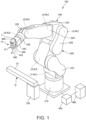
- FIG. 1 is a perspective view showing the entire configuration of a robot system 100 according to the first embodiment.
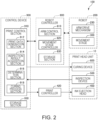
- FIG. 2 is a functional block diagram of the robot system 100 shown in FIG. 1 .
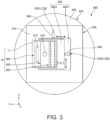
- FIG. 3 is a plan view showing a print head unit 10 shown in FIG. 1 .
- the robot system 100 shown in FIG. 1 includes a robot 200, the print head unit 10 (print head unit according to the first embodiment), a fixing member 700 that supports and fixes an object Q, and a control device 900.
- the robot 200 is a six axes vertical articulated robot including six drive axes.
- the robot 200 includes a base 210 fixed to a floor, a robot arm 220 connected to the base 210, and a movement stage 300 attached to the robot arm 220.
- the movement stage 300 may be provided as necessary, and may be omitted. In this case, the print head unit 10 may be directly attached to the robot arm 220.
- the number of drive axes of the robot 200 may be less than or more than six.
- the robot 200 may be a horizontal articulated robot or a multi-arm robot including a plurality of robot arms.
- the robot arm 220 is a robotic arm in which a plurality of arms 221, 222, 223, 224, 225, and 226 are rotatably connected, and includes six joints J1 to J6. Among them, the joints J2, J3, and J5 are bending joints, and the joints J1, J4, and J6 are torsional joints. Further, the robot arm 220 is provided with an arm drive mechanism 230 shown in FIG. 2 .
- the arm drive mechanism 230 includes motors M and encoders E provided in the joints J1, J2, J3, J4, J5, and J6 shown in FIG. 1 .
- the motor M is a drive source for driving each of the joints J1, J2, J3, J4, J5, and J6.
- the encoder E detects a rotation amount of the motor M (a pivot angle of an arm).
- the print head unit 10 is attached to a tip end section of the arm 226 via the movement stage 300.
- the print head unit 10 shown in FIG. 1 includes an attachment section 11, an ink ejection head 400, an inspection device 500, and a curing device 800.
- the attachment section 11 is connected to a tip end section of the arm 226 via the movement stage 300.
- the attachment section 11 supports the ink ejection head 400, the inspection device 500, and the curing device 800.
- Such an attachment section 11 is formed of, for example, a plate having sufficient rigidity. With this, it is possible to connect the ink ejection head 400, the inspection device 500, and the curing device 800 to the robot arm 220 while maintaining the mutual positional relationship.
- the configuration of the attachment section 11 is not limited thereto.
- the ink ejection head 400 includes an ink chamber (not shown), a diaphragm arranged on a wall surface of the ink chamber (not shown), and ink ejection apertures 411 connected to the ink chamber, and is configured such that ink in the ink chamber is ejected from the ink ejection apertures 411 by vibration of the diaphragm.
- the configuration of the ink ejection head 400 is not particularly limited.
- Ink ejected from the ink ejection head 400 is curable ink.
- Curable ink is ink having a characteristic of, after being ejected in an uncured state, causing a curing reaction and being cured. Since the timing of a curing reaction can be selected, it is possible to appropriately fix ink to the object Q made of various materials.
- the curable ink include an ultraviolet curable ink (UV ink) and a thermosetting ink (resin type ink).
- ultraviolet curable ink is ink which is cured in a short time by being irradiated with ultraviolet light, the range of wetting and spreading is particularly easily controlled, and the ultraviolet curable ink is useful as ink which is ejected from the ink ejection head 400.
- thermosetting inks that are water-based inks. Water-based ink is useful as ink that generates little odor and is easy to handle.
- the robot system 100 includes a print controller 420. As shown in FIG. 2 , the ink ejection head 400 is connected to the print controller 420. In the example of FIG. 1 , the print controller 420 is attached to a tip end section of the arm 226 via the movement stage 300 similarly to the ink ejection head 400. The print controller 420 controls operation of the ink ejection head 400 based on control signals output from the control device 900.
- the print controller 420 includes, for example, a processor such as one or more central processing units (CPUs), a memory, an external interface, and the like.
- the print controller 420 may include a programmable logic device such as a field programmable gate array (FPGA) instead of the CPU or in addition to the CPU.
- the print controller 420 may be incorporated into the control device 900.
- the inspection device 500 includes an imaging section 510.
- the imaging section 510 images the ink ejected onto the object Q.
- the ejected ink can be inspected based on the image captured by the imaging section 510.
- "inspection” refers to capturing an image of an ink film formed with ejected ink.
- the inspection device 500 is included in the print head unit 10, but may not necessarily be included.
- the inspection device 500 may be provided at an arbitrary position of the robot arm 220, or may be provided at a position different from the robot arm 220.
- Example of a position different from the robot arm 220 are, for example, a ceiling or a wall of a space in which the robot 200 is arranged, a pillar erected on a floor, or the like.
- the imaging section 510 is, for example, a camera.
- the camera include a black-and-white camera, a color camera, and a spectroscopic camera.
- the black-and-white camera and the color camera can acquire an image including at least luminance information distributed two dimensionally.
- the luminance information is a luminance value in two dimensional pixels.
- a spectroscopic camera can acquire an image including at least two dimensional luminance information and color information.
- the color information is the chromaticity and brightness in pixels.
- the curing device 800 includes an ultraviolet light irradiation section 810.
- the ultraviolet light irradiation section 810 irradiates ultraviolet light toward the ink ejected onto the object Q.
- ultraviolet curable ink can be cured and fixed.
- the curing device 800 may include a device other than the ultraviolet light irradiation section 810.
- Such devices include, for example, a resistance heating heater, an infrared heater, and the like. When these devices are used, thermosetting ink may be used as the ink.
- the curing device 800 is included in the print head unit 10, but may not necessarily be included.
- the curing device 800 may be provided at an arbitrary position of the robot arm 220, or may be provided at a position different from the robot arm 220.
- Example of a position different from the robot arm 220 are, for example, a ceiling or a wall of a space in which the robot 200 is arranged, a pillar erected on a floor, or the like.
- the movement stage 300 includes a base section 310 connected to the arm 226, a stage 320 that moves with respect to the base section 310, and a movement mechanism 330 that moves the stage 320 with respect to the base section 310.
- the stage 320 when three axes orthogonal to each other are defined as an X-axis, a Y-axis, and a Z-axis, the stage 320 includes a Y-stage 320Y movable in a direction along the Y-axis with respect to the base section 310 and an X-stage 320X movable in a direction along the X-axis with respect to the Y-stage 320Y.
- the X-stage 320X and the Y-stage 320Y are linearly guided in an X-axis direction and a Y-axis direction by a linear guide (not shown), and can smoothly move.
- the print head unit 10 is attached to the X-stage 320X.
- the stage 320 may include a rotation stage rotatable about the Z-axis with respect to the base section 310.
- the movement mechanism 330 includes a Y-movement mechanism 330Y which moves the Y-stage 320Y in a direction along the Y-axis with respect to the base section 310 and an X-movement mechanism 330X which moves the X-stage 320X in a direction along the X-axis with respect to the Y-stage 320Y.
- the Y-movement mechanism 330Y and the X-movement mechanism 330X each include a piezoelectric actuator 340 as a drive source.
- the piezoelectric actuators 340 vibrates using expansion and contraction of piezoelectric elements, and move the X-stage 320X and the Y-stage 320Y by transmitting the vibration to the X-stage 320X and the Y-stage 320Y. That is, the movement stage 300 is configured to move the print head unit 10 with respect to the robot arm 220 by piezo drive. This makes it possible to reduce the size and weight of the movement stage 300. Further, the drive accuracy of the movement stage 300 is improved.
- the drive source may be an actuator other than the piezoelectric actuator 340.
- the robot system 100 includes a robot controller 600.
- the motors M and the encoders E are connected to the robot controller 600.
- the robot controller 600 controls an operation of the robot 200 based on a control signal output from the control device 900.
- the robot controller 600 includes, as functional sections, an arm control section 610, a movement stage controller 620, and a storage section 630.
- the arm control section 610 controls the robot arm 220 to a target posture by outputting a control signal for controlling an operation of the arm drive mechanism 230.
- the movement stage controller 620 moves the print head unit 10 to a target position with respect to the robot arm 220 by outputting a control signal for controlling an operation of the movement stage 300.
- the movement stage controller 620 may be independent of the robot controller 600.
- the storage section 630 stores a program necessary for processing in the robot controller 600, data necessary for execution of the program, and the like.
- the robot controller 600 includes, for example, a processor, such as one or more CPUs, a memory, an external interface, and the like.
- the robot controller 600 may include a programmable logic device such as an FPGA instead of the CPU or in addition to the CPU.
- the control device 900 controls each operation of the robot controller 600, the print controller 420, the inspection device 500, and the curing device 800 to execute printing onto the object Q.
- the control device 900 includes a print control section 910 and a storage section 930 as functional sections.
- the print control section 910 includes a print data generation section 912, an inspection result acquisition section 914, a determination section 916, and a curing process section 918.
- the print data generation section 912 generates print data and outputs it to the robot controller 600 and the print controller 420.
- Print data is data constituting characters, images, and the like to be printed on the object Q.
- the inspection result acquisition section 914 controls operation of the inspection device 500 and causes the inspection device 500 to image ink immediately after the ink is ejected onto a print surface Q1 of the object Q. Then, the obtained image is output as an inspection result and acquired.
- the determination section 916 determines whether an inspection result acquired by the inspection result acquisition section 914 is acceptable or not.
- a determination method for determining whether an inspection result is pass or fail for example, in the case where an inspection result is an image including two dimensional luminance information, a method of determining whether or not a pattern constituted by position and shape of the ejected ink matches a pattern included in a template image registered in advance, that is, an acceptability criterion can be given. In this determination, whether an inspection result is acceptable or not is determined based on a known template matching technique.
- a method of determining whether or not the chromaticity and the brightness consisting of the hue and the saturation of the ejected ink satisfy an acceptability criterion registered in advance can be given.
- a method of determining whether or not the difference (color difference ⁇ E) between color information included in an inspection result and a reference color is within a predetermined range can be given.
- the determination section 916 determines that an acceptability criterion is satisfied and that the inspection result is pass and, in a case where the color difference ⁇ E is not within the predetermined range, determines that the acceptability criterion is not satisfied and the inspection result is fail (is not pass).
- the curing process section 918 controls curing of an ink film by the curing device 800. Then, when the determination by the determination section 916 is pass, ultraviolet light is irradiated from the curing device 800 to cure the ink that was the target of inspection. On the other hand, when a determination by the determination section 916 is fail, the curing device 800 does not irradiate ultraviolet light.
- the storage section 930 stores a program necessary for an operation of the control device 900, data necessary for the execution of the program, and the like.
- the control device 900 is constituted by, for example, a computer, and includes a processor (CPU) that processes information, a memory that is communicably connected to the processor, and an external interface. Various programs that can be executed by the processor are stored in the memory, and the processor realizes the above-described functions by reading and executing the various programs and the like stored in the memory.
- the control device 900 may include a programmable logic device such as an FPGA instead of the CPU or in addition to the CPU.
- the movement stage 300 may be attached to a position separated from the robot arm 220, for example, the fixing member 700, and may support the object Q.
- the movement stage 300 may be configured to finely adjust a position of the object Q in synchronization with an operation of the robot arm 220.
- the movement stage 300 may have a function of moving the print head unit 10 so as to cancel shaking of the robot arm 220 in an orthogonal direction D2 orthogonal to a printing direction D1 (to be described later), for example.
- FIG. 4 is a flowchart for explaining a printing method according to the first embodiment.
- FIGS. 5 to 9 are diagrams for explaining the printing method shown in FIG. 4 , and are diagrams for explaining an operation of the robot system 100 in each step shown in FIG. 4 .
- the printing method according to the first embodiment is a method in which the ink ejection head 400 ejects ink 40 to perform printing on the object Q while the robot 200 causes the print head unit 10 to scan the object Q in the printing direction D1.
- the printing method shown in FIG. 4 includes an ink ejecting step S102, an inspecting step S104, a determining step S106, an ink removing step S108, and a curing step S110.
- each step will be described in order.
- the print data generation section 912 of the print control section 910 acquires the shape, size, and the like of the print surface Q1 of the object Q. Then, operating conditions of the robot 200 on the print surface Q1 are determined.
- the operating conditions are not particularly limited, and examples thereof include a posture, a movement path, acceleration, deceleration, the maximum speed, and the like of the robot arm 220 on the print surface Q1, and the movement amount, the movement speed, and the like of the movement stage 300. These operating conditions are set by the print data generation section 912 based on information previously input to the print control section 910, image data appropriately input thereto, and the like.
- print data generated by the print data generation section 912 is output to the robot controller 600 and the print controller 420.
- the robot controller 600 controls operation of the robot 200 based on print data.
- the print controller 420 controls operation of the ink ejection head 400 based on print data.
- the ink ejection head 400 ejects the ink 40 toward the print surface Q1 while the robot 200 causes the print head unit 10 to scan in the printing direction D1.
- the ejected ink 40 lands in a range (a predetermined range) set in print data to form an ink film 42.
- the "predetermined range” refers to a minimum unit region in which inspection and curing are performed after formation of the ink film 42 in steps to be described later.
- the ink 40 ejected onto the print surface Q1, that is, the ink film 42 formed on the print surface Q1, is inspected.
- the ink film 42 is imaged by the inspection device 500.
- the inspection result acquisition section 914 of the control device 900 acquires the obtained image as an inspection result. Since the inspection device 500 is incorporated into the print head unit 10, inspection of the ink film 42 can be performed for each predetermined range. As a result, the size of an image for inspection can be small, and the inspection device 500 can be simplified. Therefore, it is possible to speed up the inspecting step S104 and the determining step S106. In addition, since it is possible to suppress the waiting time of inspection from becoming long, it is possible to suppress a change such as unintended wetting and spreading from occurring in the ink film 42.
- the ink film 42 in the predetermined range may be formed in a plurality of units, and then the ink film 42 in a plurality of units may be collectively inspected.
- the predetermined range of the ink film 42 is not particularly limited, and is set in consideration of, for example, an inspection range of the inspection device 500, the drying time of the ink 40, and the like.
- the determination section 916 of the control device 900 determines whether or not an inspection result is pass in reference to the acceptability criterion.
- the process proceeds to the curing step S110 .
- the inspection result is fail, that is, is not pass, the process proceeds to the ink removing step S108.
- an ink film 42 of which the inspection result is fail an ink film 42 with a printing failure
- the ink 40 ejected onto the print surface Q1, that is, the ink film 42 is removed.
- the object Q can be reused, and wasteful disposal of the object Q can be prevented.
- the ink film 42 is composed of uncured ink 40, it can be removed by various removing methods. As a method of removing the ink film 42, for example, wiping, blotting, washing, or the like can be given.
- the curing step S110 when the inspection result is pass, then, as shown in FIG. 7 , a curing process of irradiating ultraviolet light UV is performed on the ink film 42 that was the target of inspection. Thereby, the ink film 42 is cured, and the cured ink film 44 shown in FIG. 8 is obtained. As described above, the cured film 44 in which print data is faithfully reflected is obtained. According to the printing method as described above, it is possible to prevent the cured film 44, in which a printing failure occurred, from being generated. Therefore, it is possible to obtain a print result of a target shape.
- Curing of the ink film 42 is performed for each predetermined range.
- an irradiation range of ultraviolet light UV can be reduced, the curing device 800 can be reduced in size.
- the ink film 42 in a predetermined range may be inspected in a plurality of units, and then the ink film 42 in a plurality of units may be cured collectively.
- the cured film 44 By repeating the formation of the cured film 44 by the printing method as described above, the cured film 44 can be continuously formed as shown in FIG. 9 . Thereby, a cured film 46 in which print data is reflected can be obtained.
- the ink ejection head 400, the inspection device 500, and the curing device 800 are arranged in this order, and are integrally scanned by the robot 200. Therefore, when the print head unit 10 is scanned in the printing direction D1 immediately after the ink film 42 is formed by the ink ejection head 400, the inspection device 500 and the curing device 800 are sequentially moved onto the ink film 42. By this, ejection of the ink 40, inspection of the ink film 42, and curing of the ink film 42 can be continuously performed. As a result, it is possible to suppress the occurrence of printing failures one after another and to efficiently obtain highly accurate print results.
- FIGS. 10 to 12 are side views showing a partial configuration of the robot system 100 according to the second embodiment.
- FIGS. 10 to 12 the same components as those of the first embodiment are denoted by the same reference symbols.
- the robot system 100 according to the second embodiment is the same as the robot system 100 according to the first embodiment except that the ink ejection head 400, the inspection device 500, and the curing device 800 are attached to a robot 200A, a robot 200B, and a robot 200C, which are different from each other.
- the ink 40 is ejected from the ink ejection head 400 attached to the robot 200A. Then, the ink film 42 is formed on the print surface Q1.
- the inspection device 500 attached to the robot 200B on the ink film 42 is moved. Then, as shown in FIG. 11 , the inspection device 500 inspects the ink film 42.
- the curing device 800 attached to the robot 200C is moved over the ink film 42. Then, as shown in FIG. 12 , the ink film 42 is cured by the curing device 800. Thereby, the same cured film 44 as in FIG. 8 is obtained.
- the timing of inspection of the ink film 42 and the timing of curing the ink film 42 can be freely adjusted. Therefore, for example, it is also possible to perform inspection or curing after waiting for the ejected ink 40 to wet and spread. This makes it possible to perform inspection and curing according to the characteristics of the ink 40, thereby making it possible to form the cured film 44 of higher quality.
- any two of the ink ejection head 400, the inspection device 500, and the curing device 800 may be attached to one robot, and the remaining one may be attached to another robot.
- FIG. 13 is a flowchart for explaining a printing method according to the third embodiment.
- FIG. 14 is a side view showing a partial configuration of the print head unit 10 and the robot system 100 used in the printing method shown in FIG. 13 .
- FIGS. 13 and 14 the same components as those of the first embodiment are denoted by the same reference symbols.
- the printing method according to the third embodiment is the same as the printing method according to the first embodiment except that a provisional curing step S120 is included.
- the print head unit 10 and the robot system 100 according to the third embodiment are the same as the print head unit 10 and the robot system 100 according to the first embodiment except that a provisional curing device 850 is provided.
- the printing method shown in FIG. 13 includes, in addition to the steps shown in FIG. 4 , the provisional curing step S120 provided between the ink ejecting step S102 and the inspecting step S104.
- the provisional curing step S120 the ink 40 ejected onto the print surface Q1, that is, the ink film 42 formed on the print surface Q1, is provisionally cured.
- the provisional curing is performed using the provisional curing device 850 shown in FIG. 14 .
- the provisional curing device 850 shown in FIG. 14 is the same as the curing device 800 shown in FIG. 3 , except that the cumulative amount of ultraviolet light to be irradiated is set to be smaller than the cumulative amount of ultraviolet light irradiated by the curing device 800. Since the cumulative amount of ultraviolet light is set to be small, even when the ink film 42 is irradiated with ultraviolet light from the provisional curing device 850, the ink film 42 does not reach curing and remains in a state of provisional curing (semi-cured).
- the provisionally cured ink film 42 can be removed in the ink removing step S108.
- the provisionally cured ink film 42 is less likely to wet and spread as compared with the ink film 42 immediately after formation. Therefore, a landing position of the ink 40 is accurately reflected on the provisionally cured ink film 42, and the ink film 42 has a desired shape.
- the ink ejection head 400, the provisional curing device 850, the inspection device 500, and the curing device 800 are arranged in this order, and are integrally scanned by the robot 200. Therefore, when the print head unit 10 is scanned in the printing direction D1 immediately after the ink film 42 is formed by the ink ejection head 400, the provisional curing device 850, the inspection device 500, and the curing device 800 are sequentially moved over the ink film 42. Thereby, ejection of the ink 40, provisional curing of the ink film 42, inspection of the ink film 42, and curing of the ink film 42 can be continuously performed. As a result, the cured film 44 with high accuracy can be continuously formed, and a print result with high accuracy can be obtained.
- the printing method according to the embodiment is a printing method for performing printing on the object Q by using the ink ejection head 400 and the robot 200, in which the ink ejection head 400 ejects the ink 40 (curable ink) and prints on the object Q while the robot 200 scans the ink ejection head 400.
- the robot 200 includes the robot arm 220 that supports and moves the ink ejection head 400.
- the printing method includes the ink ejecting step S102, the inspecting step S104, the determining step S106, and the curing step S110. In the ink ejecting step S102, the ink ejection head 400 ejects the ink 40 toward the object Q.
- the inspecting step S104 the ink 40 ejected onto the object Q is inspected, and an inspection result is output.
- the determining step S106 it is determined whether or not the inspection result is pass.
- the curing step S110 the ink 40 ejected onto the object Q is cured when the inspection result is pass.
- the ink 40 (curable ink) is an ink which is cured by irradiation of ultraviolet light UV.
- ultraviolet curable ink is ink which is cured in a short time by being irradiated with ultraviolet light UV, the range of wetting and spreading is particularly easily controlled.
- the inspection result described above may include a two dimensional image obtained by imaging the ink 40 (curable ink) ejected onto the object Q.
- the determining step S106 step of determining whether or not the inspection result is pass
- a two dimensional image can be used for inspection of the position and shape of the ink 40 ejected onto the object Q. For this reason, template matching can be performed on a pattern formed by the position and shape of the ink 40. By this, a determination of whether the inspection result is pass or fail can be performed more easily and accurately.
- the inspection result described above may include color information acquired from the ink 40 (curable ink) ejected onto the object Q.
- the determining step S106 step of determining whether or not the inspection result is pass
- the color of the ink 40 ejected onto the object Q can be included in the inspection result. As a result, it is possible to suppress the occurrence of color defects in a print result.
- the printing method may include the ink removing step S108 of removing the ink 40 (curable ink) ejected onto the object Q in a case where the inspection result described above is negative.
- the printing method according to the embodiment includes a provisional curing step S120, if necessary.
- the provisional curing step S120 is provided before the inspecting step S104 (step of outputting an inspection result), and the ink 40 (curable ink) ejected onto the object Q is provisionally cured.
- a provisionally cured ink film 42 is obtained that is in a state of being unlikely to wet and spread, as compared with the ink film 42 immediately after formation.
- the provisionally cured ink film 42 accurately reflects a landing position of the ink 40, and has an intended shape.
- the provisionally cured ink film 42 can be removed in the ink removing step S108.
- the print head unit 10 is supported by the robot arm 220, and performs printing by being scanned with respect to the object Q.
- the print head unit 10 includes the attachment section 11, the ink ejection head 400, the inspection device 500, and the curing device 800.
- the attachment section 11 is attached to the robot arm 220.
- the ink ejection head 400 ejects the ink 40 (curable ink).
- the inspection device 500 inspects the ejected ink 40.
- the curing device 800 cures the ejected ink 40.
- the ink ejection head 400, the inspection device 500, and the curing device 800 are arranged in this order.
- the print head unit 10 is integrally scanned, ejection of the ink 40, inspection of the ink film 42, and curing of the ink film 42 can be continuously performed. Thereby, the cured film 44 with high accuracy can be continuously formed, and a print result with high accuracy can be obtained.
- the robot system 100 is a robot system which performs printing on the object Q, and includes the ink ejection head 400, the robot 200, the inspection device 500, the curing device 800, and the control device 900.
- the ink ejection head 400 ejects the ink 40 (curable ink).
- the robot 200 includes the robot arm 220 that supports and moves the ink ejection head 400.
- the inspection device 500 inspects the ejected ink 40 .
- the curing device 800 cures the ejected ink 40.
- the control device 900 performs printing by controlling each operation of the ink ejection head 400, the robot 200, the inspection device 500, and the curing device 800.
- the control device 900 includes the inspection result acquisition section 914, the determination section 916, and the curing process section 918.
- the inspection result acquisition section 914 acquires an inspection result output from the inspection device 500.
- the determination section 916 determines whether or not the inspection result is pass.
- the curing process section 918 causes the curing device 800 to cure the ink 40 when the inspection result is pass.
- the printing method, the print head unit, and the robot system of the present disclosure have been described based on the shown embodiments, the printing method, the print head unit, and the robot system of the present disclosure are not limited to the above embodiments.
- the printing method of the present disclosure may be one in which any desired process or operation is added to the above-described embodiment.
- the print head unit and the robot system of the present disclosure may be those in which each part of the above-described embodiment is replaced with an arbitrary configuration having a similar function, or may be those in which an arbitrary configuration is added to the above-described embodiment.
Landscapes
- Health & Medical Sciences (AREA)
- General Health & Medical Sciences (AREA)
- Toxicology (AREA)
- Engineering & Computer Science (AREA)
- Manufacturing & Machinery (AREA)
- Physics & Mathematics (AREA)
- Electromagnetism (AREA)
- Ink Jet (AREA)
- Coating Apparatus (AREA)
- Spray Control Apparatus (AREA)
Abstract
A printing method for performing printing on an object by using an ink ejection head and a robot including a robot arm that supports and moves the ink ejection head, in which the ink ejection head ejects curable ink and prints on the object while the robot scans the ink ejection head, the printing method includes a step of the ink ejection head ejecting the curable ink toward the object; a step of inspecting the curable ink ejected onto the object and outputting an inspection result; a step of determining whether the inspection result is pass or fail; and a step of curing the curable ink ejected onto the object when the inspection result is pass.
Description
- The present application is based on, and claims priority from
JP Application Serial Number 2023-082096, filed May 18, 2023 - The present invention relates to a printing method, a print head unit, and a robot system.
- There is known a three dimensional object printing device that performs printing on a surface of a three dimensional object by moving an inkjet print head by combining operations of a plurality of movable sections.
- For example,
JP-A-2013-202781 - Curable ink can also be used in inkjet printing. Curable ink is cured by, for example, being irradiated with ultraviolet light or being heated after being ejected onto an object. Therefore, there is a problem that it is difficult to remove the ink that has been completely cured, and even when a print result is defective, it cannot be corrected. Therefore, it is required to realize a printing method capable of correcting a print result even when the printing result is defective in printing performed by a robot ejecting curable ink.
- A printing method according to an application example of the present disclosure is a printing method for performing printing on an object by using an ink ejection head and a robot including a robot arm that supports and moves the ink ejection head, in which the ink ejection head ejects curable ink and prints on the object while the robot scans the ink ejection head, the printing method including a step of the ink ejection head ejecting the curable ink toward the object; a step of inspecting the curable ink ejected onto the object and outputting an inspection result; a step of determining whether the inspection result is pass or fail; and a step of curing the curable ink ejected onto the object when the inspection result is pass.
- A print head unit according to an application example of the present disclosure is a print head unit supported by a robot arm and configured to perform printing by being scanned with respect to an object, the print head unit including an attachment section configured to attach to a robot arm; an ink ejection head that ejects curable ink; an inspection device that inspects the ejected curable ink; and a curing device that cures the ejected curable ink.
- A robot system according to an application example of the present disclosure is a robot system for performing printing onto an object, the robot system including an ink ejection head that ejects curable ink; a robot including a robot arm that supports and moves the ink ejection head; an inspection device that inspects the ejected curable ink; a curing device that cures the ejected curable ink; and a control device that performs the printing by controlling each operation of the ink ejection head, the robot, the inspection device, and the curing device, wherein the control device includes an inspection result acquisition section that acquires an inspection result output from the inspection device, a determination section that determines whether the inspection result is pass or fail, and a curing process section that causes the curing device to cure the curable ink when the inspection result is pass.
-
-
FIG. 1 is a perspective view showing the entire configuration of a robot system according to a first embodiment. -
FIG. 2 is a functional block diagram of the robot system shown inFIG. 1 . -
FIG. 3 is a plan view showing a print head unit shown inFIG. 1 . -
FIG. 4 is a flowchart for explaining a printing method according to the first embodiment. -
FIG. 5 is a diagram for explaining the printing method shown inFIG. 4 , and is a diagram for explaining an operation of the robot system in each step shown inFIG. 4 . -
FIG. 6 is a diagram for explaining the printing method shown inFIG. 4 , and is a diagram for explaining an operation of the robot system in each step shown inFIG. 4 . -
FIG. 7 is a diagram for explaining the printing method shown inFIG. 4 , and is a diagram for explaining an operation of the robot system in each step shown inFIG. 4 . -
FIG. 8 is a diagram for explaining the printing method shown inFIG. 4 , and is a diagram for explaining an operation of the robot system in each step shown inFIG. 4 . -
FIG. 9 is a diagram for explaining the printing method shown inFIG. 4 , and is a diagram for explaining an operation of the robot system in each step shown inFIG. 4 . -
FIG. 10 is a side view showing a partial configuration of the robot system according to a second embodiment. -
Fig. 11 is a side view showing a partial configuration of the robot system according to the second embodiment. -
Fig. 12 is a side view showing a partial configuration of the robot system according to the second embodiment. -
FIG. 13 is a flowchart for explaining a printing method according to a third embodiment. -
FIG. 14 is a side view showing a partial configuration of the print head unit and the robot system used in a printing method shown inFIG. 13 . - Hereinafter, preferred embodiments of a printing method, a print head unit and a robot system of the present disclosure will be described in detail with reference to the accompanying drawings.
- First, a printing method, a print head unit, and a robot system according to a first embodiment will be described.
-
FIG. 1 is a perspective view showing the entire configuration of arobot system 100 according to the first embodiment.FIG. 2 is a functional block diagram of therobot system 100 shown inFIG. 1 .FIG. 3 is a plan view showing aprint head unit 10 shown inFIG. 1 . - The
robot system 100 shown inFIG. 1 includes arobot 200, the print head unit 10 (print head unit according to the first embodiment), afixing member 700 that supports and fixes an object Q, and acontrol device 900. - The
robot 200 is a six axes vertical articulated robot including six drive axes. Therobot 200 includes abase 210 fixed to a floor, arobot arm 220 connected to thebase 210, and amovement stage 300 attached to therobot arm 220. Themovement stage 300 may be provided as necessary, and may be omitted. In this case, theprint head unit 10 may be directly attached to therobot arm 220. The number of drive axes of therobot 200 may be less than or more than six. Therobot 200 may be a horizontal articulated robot or a multi-arm robot including a plurality of robot arms. - The
robot arm 220 is a robotic arm in which a plurality ofarms robot arm 220 is provided with anarm drive mechanism 230 shown inFIG. 2 . Thearm drive mechanism 230 includes motors M and encoders E provided in the joints J1, J2, J3, J4, J5, and J6 shown inFIG. 1 . The motor M is a drive source for driving each of the joints J1, J2, J3, J4, J5, and J6. The encoder E detects a rotation amount of the motor M (a pivot angle of an arm). - As shown in
FIG. 1 , theprint head unit 10 is attached to a tip end section of thearm 226 via themovement stage 300. Theprint head unit 10 shown inFIG. 1 includes anattachment section 11, anink ejection head 400, aninspection device 500, and acuring device 800. - The
attachment section 11 is connected to a tip end section of thearm 226 via themovement stage 300. Theattachment section 11 supports theink ejection head 400, theinspection device 500, and thecuring device 800. Such anattachment section 11 is formed of, for example, a plate having sufficient rigidity. With this, it is possible to connect theink ejection head 400, theinspection device 500, and thecuring device 800 to therobot arm 220 while maintaining the mutual positional relationship. The configuration of theattachment section 11 is not limited thereto. - As shown in
FIG. 3 , theink ejection head 400 includes an ink chamber (not shown), a diaphragm arranged on a wall surface of the ink chamber (not shown), andink ejection apertures 411 connected to the ink chamber, and is configured such that ink in the ink chamber is ejected from theink ejection apertures 411 by vibration of the diaphragm. However, the configuration of theink ejection head 400 is not particularly limited. - Ink ejected from the
ink ejection head 400 is curable ink. Curable ink is ink having a characteristic of, after being ejected in an uncured state, causing a curing reaction and being cured. Since the timing of a curing reaction can be selected, it is possible to appropriately fix ink to the object Q made of various materials. Examples of the curable ink include an ultraviolet curable ink (UV ink) and a thermosetting ink (resin type ink). Among these, since ultraviolet curable ink is ink which is cured in a short time by being irradiated with ultraviolet light, the range of wetting and spreading is particularly easily controlled, and the ultraviolet curable ink is useful as ink which is ejected from theink ejection head 400. On the other hand, there are also thermosetting inks that are water-based inks. Water-based ink is useful as ink that generates little odor and is easy to handle. - The
robot system 100 includes aprint controller 420. As shown inFIG. 2 , theink ejection head 400 is connected to theprint controller 420. In the example ofFIG. 1 , theprint controller 420 is attached to a tip end section of thearm 226 via themovement stage 300 similarly to theink ejection head 400. Theprint controller 420 controls operation of theink ejection head 400 based on control signals output from thecontrol device 900. - The
print controller 420 includes, for example, a processor such as one or more central processing units (CPUs), a memory, an external interface, and the like. Theprint controller 420 may include a programmable logic device such as a field programmable gate array (FPGA) instead of the CPU or in addition to the CPU. Theprint controller 420 may be incorporated into thecontrol device 900. - As shown in
FIG. 3 , theinspection device 500 includes animaging section 510. Theimaging section 510 images the ink ejected onto the object Q. The ejected ink can be inspected based on the image captured by theimaging section 510. In the present specification, "inspection" refers to capturing an image of an ink film formed with ejected ink. - In the present embodiment, the
inspection device 500 is included in theprint head unit 10, but may not necessarily be included. In this case, for example, theinspection device 500 may be provided at an arbitrary position of therobot arm 220, or may be provided at a position different from therobot arm 220. Example of a position different from therobot arm 220 are, for example, a ceiling or a wall of a space in which therobot 200 is arranged, a pillar erected on a floor, or the like. - The
imaging section 510 is, for example, a camera. Examples of the camera include a black-and-white camera, a color camera, and a spectroscopic camera. - Among these cameras, the black-and-white camera and the color camera can acquire an image including at least luminance information distributed two dimensionally. The luminance information is a luminance value in two dimensional pixels. By using such an image, it is possible to inspect a position and a shape of the ink ejected onto the object Q.
- A spectroscopic camera can acquire an image including at least two dimensional luminance information and color information. The color information is the chromaticity and brightness in pixels. By using an image with such color information, it is possible to inspect not only the position and the shape of the ink ejected onto the object Q, but also the color of the ink, that is, the type of the ink.
- As shown in
FIG. 3 , thecuring device 800 includes an ultravioletlight irradiation section 810. The ultravioletlight irradiation section 810 irradiates ultraviolet light toward the ink ejected onto the object Q. By this, ultraviolet curable ink can be cured and fixed. - The
curing device 800 may include a device other than the ultravioletlight irradiation section 810. Such devices include, for example, a resistance heating heater, an infrared heater, and the like. When these devices are used, thermosetting ink may be used as the ink. - In the present embodiment, the
curing device 800 is included in theprint head unit 10, but may not necessarily be included. In this case, for example, thecuring device 800 may be provided at an arbitrary position of therobot arm 220, or may be provided at a position different from therobot arm 220. Example of a position different from therobot arm 220 are, for example, a ceiling or a wall of a space in which therobot 200 is arranged, a pillar erected on a floor, or the like. - As shown in
FIG. 3 , themovement stage 300 includes abase section 310 connected to thearm 226, astage 320 that moves with respect to thebase section 310, and amovement mechanism 330 that moves thestage 320 with respect to thebase section 310. As shown inFIG. 3 , when three axes orthogonal to each other are defined as an X-axis, a Y-axis, and a Z-axis, thestage 320 includes a Y-stage 320Y movable in a direction along the Y-axis with respect to thebase section 310 and an X-stage 320X movable in a direction along the X-axis with respect to the Y-stage 320Y. The X-stage 320X and the Y-stage 320Y are linearly guided in an X-axis direction and a Y-axis direction by a linear guide (not shown), and can smoothly move. Theprint head unit 10 is attached to the X-stage 320X. Thestage 320 may include a rotation stage rotatable about the Z-axis with respect to thebase section 310. - The
movement mechanism 330 includes a Y-movement mechanism 330Y which moves the Y-stage 320Y in a direction along the Y-axis with respect to thebase section 310 and anX-movement mechanism 330X which moves the X-stage 320X in a direction along the X-axis with respect to the Y-stage 320Y. - The Y-
movement mechanism 330Y and theX-movement mechanism 330X each include apiezoelectric actuator 340 as a drive source. Thepiezoelectric actuators 340 vibrates using expansion and contraction of piezoelectric elements, and move the X-stage 320X and the Y-stage 320Y by transmitting the vibration to theX-stage 320X and the Y-stage 320Y. That is, themovement stage 300 is configured to move theprint head unit 10 with respect to therobot arm 220 by piezo drive. This makes it possible to reduce the size and weight of themovement stage 300. Further, the drive accuracy of themovement stage 300 is improved. Furthermore, since thepiezoelectric actuator 340 has a large holding torque at the time of stopping, it is also useful that there is no need to add a brake and that the positional stability of thestage 320 at the time of stoppin is high. The drive source may be an actuator other than thepiezoelectric actuator 340. - As shown in
FIGS. 1 and2 , therobot system 100 includes arobot controller 600. The motors M and the encoders E are connected to therobot controller 600. Therobot controller 600 controls an operation of therobot 200 based on a control signal output from thecontrol device 900. - The
robot controller 600 includes, as functional sections, anarm control section 610, amovement stage controller 620, and astorage section 630. - The
arm control section 610 controls therobot arm 220 to a target posture by outputting a control signal for controlling an operation of thearm drive mechanism 230. - The
movement stage controller 620 moves theprint head unit 10 to a target position with respect to therobot arm 220 by outputting a control signal for controlling an operation of themovement stage 300. Themovement stage controller 620 may be independent of therobot controller 600. - The
storage section 630 stores a program necessary for processing in therobot controller 600, data necessary for execution of the program, and the like. - The
robot controller 600 includes, for example, a processor, such as one or more CPUs, a memory, an external interface, and the like. Therobot controller 600 may include a programmable logic device such as an FPGA instead of the CPU or in addition to the CPU. - The
control device 900 controls each operation of therobot controller 600, theprint controller 420, theinspection device 500, and thecuring device 800 to execute printing onto the object Q. As shown inFIG. 2 , thecontrol device 900 includes aprint control section 910 and astorage section 930 as functional sections. Theprint control section 910 includes a printdata generation section 912, an inspectionresult acquisition section 914, adetermination section 916, and acuring process section 918. - The print
data generation section 912 generates print data and outputs it to therobot controller 600 and theprint controller 420. Print data is data constituting characters, images, and the like to be printed on the object Q. - The inspection result
acquisition section 914 controls operation of theinspection device 500 and causes theinspection device 500 to image ink immediately after the ink is ejected onto a print surface Q1 of the object Q. Then, the obtained image is output as an inspection result and acquired. - The
determination section 916 determines whether an inspection result acquired by the inspectionresult acquisition section 914 is acceptable or not. As a determination method for determining whether an inspection result is pass or fail, for example, in the case where an inspection result is an image including two dimensional luminance information, a method of determining whether or not a pattern constituted by position and shape of the ejected ink matches a pattern included in a template image registered in advance, that is, an acceptability criterion can be given. In this determination, whether an inspection result is acceptable or not is determined based on a known template matching technique. - When the inspection result is an image including color information, a method of determining whether or not the chromaticity and the brightness consisting of the hue and the saturation of the ejected ink satisfy an acceptability criterion registered in advance can be given. Specifically, for example, in an L*a*b* colorimetric system, a method of determining whether or not the difference (color difference ΔE) between color information included in an inspection result and a reference color is within a predetermined range can be given. Then, in a case where the color difference ΔE is within a predetermined range, the
determination section 916 determines that an acceptability criterion is satisfied and that the inspection result is pass and, in a case where the color difference ΔE is not within the predetermined range, determines that the acceptability criterion is not satisfied and the inspection result is fail (is not pass). By using color information in this way, it is possible to perform a determination of whether an inspection result is pass or fail based on not only position and shape of the ejected ink but also on the color of the ink. As a result, it is possible to suppress the occurrence of color defects in a print result. - The
curing process section 918 controls curing of an ink film by thecuring device 800. Then, when the determination by thedetermination section 916 is pass, ultraviolet light is irradiated from thecuring device 800 to cure the ink that was the target of inspection. On the other hand, when a determination by thedetermination section 916 is fail, thecuring device 800 does not irradiate ultraviolet light. - The
storage section 930 stores a program necessary for an operation of thecontrol device 900, data necessary for the execution of the program, and the like. - The
control device 900 is constituted by, for example, a computer, and includes a processor (CPU) that processes information, a memory that is communicably connected to the processor, and an external interface. Various programs that can be executed by the processor are stored in the memory, and the processor realizes the above-described functions by reading and executing the various programs and the like stored in the memory. Thecontrol device 900 may include a programmable logic device such as an FPGA instead of the CPU or in addition to the CPU. - The configuration of the
robot system 100 according to the first embodiment has been described above, but themovement stage 300 may be attached to a position separated from therobot arm 220, for example, the fixingmember 700, and may support the object Q. In this case, themovement stage 300 may be configured to finely adjust a position of the object Q in synchronization with an operation of therobot arm 220. Themovement stage 300 may have a function of moving theprint head unit 10 so as to cancel shaking of therobot arm 220 in an orthogonal direction D2 orthogonal to a printing direction D1 (to be described later), for example. - Next, a printing method according to the first embodiment will be described. In the following description, a method using the above-described
robot system 100 will be described as an example. -
FIG. 4 is a flowchart for explaining a printing method according to the first embodiment.FIGS. 5 to 9 are diagrams for explaining the printing method shown inFIG. 4 , and are diagrams for explaining an operation of therobot system 100 in each step shown inFIG. 4 . - The printing method according to the first embodiment is a method in which the
ink ejection head 400 ejectsink 40 to perform printing on the object Q while therobot 200 causes theprint head unit 10 to scan the object Q in the printing direction D1. - The printing method shown in
FIG. 4 includes an ink ejecting step S102, an inspecting step S104, a determining step S106, an ink removing step S108, and a curing step S110. Hereinafter, each step will be described in order. - In the ink ejecting step S102, the print
data generation section 912 of theprint control section 910 acquires the shape, size, and the like of the print surface Q1 of the object Q. Then, operating conditions of therobot 200 on the print surface Q1 are determined. The operating conditions are not particularly limited, and examples thereof include a posture, a movement path, acceleration, deceleration, the maximum speed, and the like of therobot arm 220 on the print surface Q1, and the movement amount, the movement speed, and the like of themovement stage 300. These operating conditions are set by the printdata generation section 912 based on information previously input to theprint control section 910, image data appropriately input thereto, and the like. - Next, in the ink ejecting step S102, print data generated by the print
data generation section 912 is output to therobot controller 600 and theprint controller 420. Therobot controller 600 controls operation of therobot 200 based on print data. Theprint controller 420 controls operation of theink ejection head 400 based on print data. Then, as shown inFIG. 5 , theink ejection head 400 ejects theink 40 toward the print surface Q1 while therobot 200 causes theprint head unit 10 to scan in the printing direction D1. The ejectedink 40 lands in a range (a predetermined range) set in print data to form anink film 42. Here, the "predetermined range" refers to a minimum unit region in which inspection and curing are performed after formation of theink film 42 in steps to be described later. By repeating formation of theink film 42 and inspection and curing in the steps to be described later for each predetermined range, a target print result is finally obtained. - In the inspecting step S104, the
ink 40 ejected onto the print surface Q1, that is, theink film 42 formed on the print surface Q1, is inspected. Specifically, as shown inFIG. 6 , theink film 42 is imaged by theinspection device 500. The inspection resultacquisition section 914 of thecontrol device 900 acquires the obtained image as an inspection result. Since theinspection device 500 is incorporated into theprint head unit 10, inspection of theink film 42 can be performed for each predetermined range. As a result, the size of an image for inspection can be small, and theinspection device 500 can be simplified. Therefore, it is possible to speed up the inspecting step S104 and the determining step S106. In addition, since it is possible to suppress the waiting time of inspection from becoming long, it is possible to suppress a change such as unintended wetting and spreading from occurring in theink film 42. - Instead of performing inspection immediately after forming the
ink film 42 in the predetermined range, theink film 42 in the predetermined range may be formed in a plurality of units, and then theink film 42 in a plurality of units may be collectively inspected. The predetermined range of theink film 42 is not particularly limited, and is set in consideration of, for example, an inspection range of theinspection device 500, the drying time of theink 40, and the like. - In the determining step S106, the
determination section 916 of thecontrol device 900 determines whether or not an inspection result is pass in reference to the acceptability criterion. - When the inspection result is pass, the process proceeds to the curing step S110 . On the other hand, when the inspection result is fail, that is, is not pass, the process proceeds to the ink removing step S108. As a result, it is possible to prevent an
ink film 42 of which the inspection result is fail (anink film 42 with a printing failure) from being transferred to the curing step S110 to be described later. As a result, it is possible to ultimately obtain a print result with few failures while reducing the workload and costs for preparing a new object Q. - In the ink removing step S108, the
ink 40 ejected onto the print surface Q1, that is, theink film 42, is removed. Thus, the object Q can be reused, and wasteful disposal of the object Q can be prevented. Since theink film 42 is composed ofuncured ink 40, it can be removed by various removing methods. As a method of removing theink film 42, for example, wiping, blotting, washing, or the like can be given. - After the
ink film 42 is removed, the process returns to the ink ejecting step S102, and printing is restarted. In this case, print data is set in the ink ejecting step S102 after printing is restarted so that printing is restarted from a portion removed in the ink removing step S108. 1.2.5. Curing step - In the curing step S110, when the inspection result is pass, then, as shown in
FIG. 7 , a curing process of irradiating ultraviolet light UV is performed on theink film 42 that was the target of inspection. Thereby, theink film 42 is cured, and the curedink film 44 shown inFIG. 8 is obtained. As described above, the curedfilm 44 in which print data is faithfully reflected is obtained. According to the printing method as described above, it is possible to prevent the curedfilm 44, in which a printing failure occurred, from being generated. Therefore, it is possible to obtain a print result of a target shape. - Curing of the
ink film 42 is performed for each predetermined range. Thus, since an irradiation range of ultraviolet light UV can be reduced, thecuring device 800 can be reduced in size. In addition, since it is possible to suppress the waiting time of curing from becoming long, it is possible to suppress a change such as unintended wetting and spreading from occurring in theink film 42. - Instead of performing curing immediately after inspecting the
ink film 42 in a predetermined range, theink film 42 in a predetermined range may be inspected in a plurality of units, and then theink film 42 in a plurality of units may be cured collectively. - By repeating the formation of the cured
film 44 by the printing method as described above, the curedfilm 44 can be continuously formed as shown inFIG. 9 . Thereby, a curedfilm 46 in which print data is reflected can be obtained. - In the
print head unit 10 shown inFIG. 3 , theink ejection head 400, theinspection device 500, and thecuring device 800 are arranged in this order, and are integrally scanned by therobot 200. Therefore, when theprint head unit 10 is scanned in the printing direction D1 immediately after theink film 42 is formed by theink ejection head 400, theinspection device 500 and thecuring device 800 are sequentially moved onto theink film 42. By this, ejection of theink 40, inspection of theink film 42, and curing of theink film 42 can be continuously performed. As a result, it is possible to suppress the occurrence of printing failures one after another and to efficiently obtain highly accurate print results. - Next, a print head unit and a robot system according to a second embodiment will be described.
-
FIGS. 10 to 12 are side views showing a partial configuration of therobot system 100 according to the second embodiment. - Hereinafter, the second embodiment will be described. In the following description, mainly differences from the first embodiment will be described and description of the same matters will be omitted. In
FIGS. 10 to 12 , the same components as those of the first embodiment are denoted by the same reference symbols. - The
robot system 100 according to the second embodiment is the same as therobot system 100 according to the first embodiment except that theink ejection head 400, theinspection device 500, and thecuring device 800 are attached to arobot 200A, arobot 200B, and arobot 200C, which are different from each other. - In the second embodiment, first, as shown in
FIG. 10 , theink 40 is ejected from theink ejection head 400 attached to therobot 200A. Then, theink film 42 is formed on the print surface Q1. - Next, the
inspection device 500 attached to therobot 200B on theink film 42 is moved. Then, as shown inFIG. 11 , theinspection device 500 inspects theink film 42. - Next, it is determined whether or not the inspection result is pass, and when the inspection result is pass, the
curing device 800 attached to therobot 200C is moved over theink film 42. Then, as shown inFIG. 12 , theink film 42 is cured by thecuring device 800. Thereby, the same curedfilm 44 as inFIG. 8 is obtained. - Also in the second embodiment as described above, the same effects as those of the first embodiment can be obtained.
- Further, in the second embodiment, the timing of inspection of the
ink film 42 and the timing of curing theink film 42 can be freely adjusted. Therefore, for example, it is also possible to perform inspection or curing after waiting for the ejectedink 40 to wet and spread. This makes it possible to perform inspection and curing according to the characteristics of theink 40, thereby making it possible to form the curedfilm 44 of higher quality. - Any two of the
ink ejection head 400, theinspection device 500, and thecuring device 800 may be attached to one robot, and the remaining one may be attached to another robot. - Next, a printing method, a print head unit, and a robot system according to a third embodiment will be described.
-
FIG. 13 is a flowchart for explaining a printing method according to the third embodiment.FIG. 14 is a side view showing a partial configuration of theprint head unit 10 and therobot system 100 used in the printing method shown inFIG. 13 . - Hereinafter, the third embodiment will be described. In the following description, mainly described differences from the first embodiment will be described and the description of the same matters will be omitted. In
FIGS. 13 and14 , the same components as those of the first embodiment are denoted by the same reference symbols. - The printing method according to the third embodiment is the same as the printing method according to the first embodiment except that a provisional curing step S120 is included. The
print head unit 10 and therobot system 100 according to the third embodiment are the same as theprint head unit 10 and therobot system 100 according to the first embodiment except that aprovisional curing device 850 is provided. - The printing method shown in
FIG. 13 includes, in addition to the steps shown inFIG. 4 , the provisional curing step S120 provided between the ink ejecting step S102 and the inspecting step S104. In the provisional curing step S120, theink 40 ejected onto the print surface Q1, that is, theink film 42 formed on the print surface Q1, is provisionally cured. The provisional curing is performed using theprovisional curing device 850 shown inFIG. 14 . - The
provisional curing device 850 shown inFIG. 14 is the same as thecuring device 800 shown inFIG. 3 , except that the cumulative amount of ultraviolet light to be irradiated is set to be smaller than the cumulative amount of ultraviolet light irradiated by thecuring device 800. Since the cumulative amount of ultraviolet light is set to be small, even when theink film 42 is irradiated with ultraviolet light from theprovisional curing device 850, theink film 42 does not reach curing and remains in a state of provisional curing (semi-cured). The provisionally curedink film 42 can be removed in the ink removing step S108. The provisionally curedink film 42 is less likely to wet and spread as compared with theink film 42 immediately after formation. Therefore, a landing position of theink 40 is accurately reflected on the provisionally curedink film 42, and theink film 42 has a desired shape. - In the
print head unit 10 shown inFIG. 14 , theink ejection head 400, theprovisional curing device 850, theinspection device 500, and thecuring device 800 are arranged in this order, and are integrally scanned by therobot 200. Therefore, when theprint head unit 10 is scanned in the printing direction D1 immediately after theink film 42 is formed by theink ejection head 400, theprovisional curing device 850, theinspection device 500, and thecuring device 800 are sequentially moved over theink film 42. Thereby, ejection of theink 40, provisional curing of theink film 42, inspection of theink film 42, and curing of theink film 42 can be continuously performed. As a result, the curedfilm 44 with high accuracy can be continuously formed, and a print result with high accuracy can be obtained. - Also in the third embodiment as described above, the same effect as in the first embodiment can be obtained.
- As described above, the printing method according to the embodiment is a printing method for performing printing on the object Q by using the
ink ejection head 400 and therobot 200, in which theink ejection head 400 ejects the ink 40 (curable ink) and prints on the object Q while therobot 200 scans theink ejection head 400. Therobot 200 includes therobot arm 220 that supports and moves theink ejection head 400. The printing method includes the ink ejecting step S102, the inspecting step S104, the determining step S106, and the curing step S110. In the ink ejecting step S102, theink ejection head 400 ejects theink 40 toward the object Q. In the inspecting step S104, theink 40 ejected onto the object Q is inspected, and an inspection result is output. In the determining step S106, it is determined whether or not the inspection result is pass. In the curing step S110, theink 40 ejected onto the object Q is cured when the inspection result is pass. - According to such a configuration, even when a print result by the
ink 40, which is a curable ink, is defective, it is possible to inspect theink film 42 before curing and correct it as necessary. For this reason, it is possible to avoid discarding the object Q because of a printing failure, and it is possible to obtain print results with fewer failures while reducing workload and costs. As a result, it is possible to efficiently perform highly accurate printing on the object Q. - Further, it is desirable that the ink 40 (curable ink) is an ink which is cured by irradiation of ultraviolet light UV.
- Since ultraviolet curable ink is ink which is cured in a short time by being irradiated with ultraviolet light UV, the range of wetting and spreading is particularly easily controlled.
- The inspection result described above may include a two dimensional image obtained by imaging the ink 40 (curable ink) ejected onto the object Q. In this case, it is desirable that the determining step S106 (step of determining whether or not the inspection result is pass) includes a process of determining whether or not a two dimensional image satisfies an acceptability criterion, and when the two dimensional image satisfies the criterion, it is determined to pass.
- A two dimensional image can be used for inspection of the position and shape of the
ink 40 ejected onto the object Q. For this reason, template matching can be performed on a pattern formed by the position and shape of theink 40. By this, a determination of whether the inspection result is pass or fail can be performed more easily and accurately. - The inspection result described above may include color information acquired from the ink 40 (curable ink) ejected onto the object Q. In this case, it is desirable that the determining step S106 (step of determining whether or not the inspection result is pass) includes a process of determining whether or not color information satisfies an acceptability criterion, and when the color information satisfies the criterion, it is determined to pass.
- In the color information, the color of the
ink 40 ejected onto the object Q can be included in the inspection result. As a result, it is possible to suppress the occurrence of color defects in a print result. - The printing method may include the ink removing step S108 of removing the ink 40 (curable ink) ejected onto the object Q in a case where the inspection result described above is negative.
- According to such a configuration, it is possible to reuse the object Q by removing the
ink 40 that was determined as fail. This makes it possible to prevent wasteful disposal of the object Q. - The printing method according to the embodiment includes a provisional curing step S120, if necessary. The provisional curing step S120 is provided before the inspecting step S104 (step of outputting an inspection result), and the ink 40 (curable ink) ejected onto the object Q is provisionally cured.
- According to such a configuration, a provisionally cured
ink film 42, is obtained that is in a state of being unlikely to wet and spread, as compared with theink film 42 immediately after formation. The provisionally curedink film 42 accurately reflects a landing position of theink 40, and has an intended shape. The provisionally curedink film 42 can be removed in the ink removing step S108. - The
print head unit 10 according to the embodiment is supported by therobot arm 220, and performs printing by being scanned with respect to the object Q. Theprint head unit 10 includes theattachment section 11, theink ejection head 400, theinspection device 500, and thecuring device 800. Theattachment section 11 is attached to therobot arm 220. Theink ejection head 400 ejects the ink 40 (curable ink). Theinspection device 500 inspects the ejectedink 40. Thecuring device 800 cures the ejectedink 40. - According to such a configuration, even though a print result with the
ink 40 is defective, it is possible to obtain aprint head unit 10 that can be applied to a printing method of inspecting theink film 42 before curing it and correcting it as necessary. For this reason, it is possible to avoid discarding the object Q because of a printing failure, and it is possible to obtain print results with fewer failures while reducing workload and costs. As a result, it is possible to efficiently perform highly accurate printing on the object Q. - It is desirable that the
ink ejection head 400, theinspection device 500, and thecuring device 800 are arranged in this order. - Since the
print head unit 10 is integrally scanned, ejection of theink 40, inspection of theink film 42, and curing of theink film 42 can be continuously performed. Thereby, the curedfilm 44 with high accuracy can be continuously formed, and a print result with high accuracy can be obtained. - The
robot system 100 according to the embodiment is a robot system which performs printing on the object Q, and includes theink ejection head 400, therobot 200, theinspection device 500, thecuring device 800, and thecontrol device 900. Theink ejection head 400 ejects the ink 40 (curable ink). Therobot 200 includes therobot arm 220 that supports and moves theink ejection head 400. Theinspection device 500 inspects the ejectedink 40 . Thecuring device 800 cures the ejectedink 40. Thecontrol device 900 performs printing by controlling each operation of theink ejection head 400, therobot 200, theinspection device 500, and thecuring device 800. Thecontrol device 900 includes the inspectionresult acquisition section 914, thedetermination section 916, and thecuring process section 918. The inspection resultacquisition section 914 acquires an inspection result output from theinspection device 500. Thedetermination section 916 determines whether or not the inspection result is pass. Thecuring process section 918 causes thecuring device 800 to cure theink 40 when the inspection result is pass. - According to such a configuration, even though a print result by the
ink 40, which is curable ink, is defective, it is possible to realize therobot system 100 capable of inspecting theink film 42 before curing theink film 42 and correcting theink film 42 as necessary. By using such arobot system 100, it is possible to avoid the discarding of the object Q due to a printing failure, and it is possible to obtain a print result with few defects while reducing the workload and costs. Thus, it is possible to efficiently perform highly accurate printing on the object Q. - Although the printing method, the print head unit, and the robot system of the present disclosure have been described based on the shown embodiments, the printing method, the print head unit, and the robot system of the present disclosure are not limited to the above embodiments. For example, the printing method of the present disclosure may be one in which any desired process or operation is added to the above-described embodiment. Further, the print head unit and the robot system of the present disclosure may be those in which each part of the above-described embodiment is replaced with an arbitrary configuration having a similar function, or may be those in which an arbitrary configuration is added to the above-described embodiment.
Claims (9)
- A printing method for performing printing on an object by using an ink ejection head and a robot including a robot arm that supports and moves the ink ejection head, in which the ink ejection head ejects curable ink and prints on the object while the robot scans the ink ejection head, the printing method comprising:a step of the ink ejection head ejecting the curable ink toward the object;a step of inspecting the curable ink ejected onto the object and outputting an inspection result;a step of determining whether the inspection result is pass or fail; anda step of curing the curable ink ejected onto the object when the inspection result is pass.
- The printing method according to claim 1, wherein
the curable ink is ink that is cured by irradiation of ultraviolet light. - The printing method according to claim 1, whereinthe inspection result includes a two dimensional image obtained by imaging the curable ink ejected onto the object andthe step of determining whether the inspection result is pass or fail includes a step of determining whether or not the two dimensional image satisfies an acceptability criterion, and determining that the inspection result is pass when the two dimensional image satisfies the acceptability criterion.
- The printing method according to claim 1, whereinthe inspection result includes color information acquired from the curable ink ejected onto the object andthe step of determining whether the inspection result is pass or fail includes a step of determining whether or not the color information satisfies an acceptability criterion, and determining that the inspection result is pass when the two dimensional image satisfies the acceptability criterion.
- The printing method according to claim 1, further comprising:
a step of removing the curable ink ejected to the object when the inspection result is negative. - The printing method according to claim 1, further comprising:
a step of provisional curing the curable ink ejected onto the object before the step of outputting the inspection result. - A print head unit supported by a robot arm and configured to perform printing by being scanned with respect to an object, the print head unit comprising:an attachment section configured to attach to a robot arm;an ink ejection head that ejects curable ink;an inspection device that inspects the ejected curable ink; anda curing device that cures the ejected curable ink.
- The print head unit according to claim 7, wherein
the ink ejection head, the inspection device, and the curing device are arranged in this order. - A robot system for performing printing onto an object, the robot system comprising:an ink ejection head that ejects curable ink;a robot including a robot arm that supports and moves the ink ejection head;an inspection device that inspects the ejected curable ink;a curing device that cures the ejected curable ink; anda control device that performs the printing by controlling each operation of the ink ejection head, the robot, the inspection device, and the curing device, whereinthe control device includesan inspection result acquisition section that acquires an inspection result output from the inspection device,a determination section that determines whether the inspection result is pass or fail, anda curing process section that causes the curing device to cure the curable ink when the inspection result is pass.
Applications Claiming Priority (1)
| Application Number | Priority Date | Filing Date | Title |
|---|---|---|---|
| JP2023082096A JP2024165695A (en) | 2023-05-18 | 2023-05-18 | Printing method, print head unit and robot system |
Publications (1)
| Publication Number | Publication Date |
|---|---|
| EP4464514A1 true EP4464514A1 (en) | 2024-11-20 |
Family
ID=91129467
Family Applications (1)
| Application Number | Title | Priority Date | Filing Date |
|---|---|---|---|
| EP24176139.4A Pending EP4464514A1 (en) | 2023-05-18 | 2024-05-15 | Printing method, print head unit, and robot system |
Country Status (3)
| Country | Link |
|---|---|
| EP (1) | EP4464514A1 (en) |
| JP (1) | JP2024165695A (en) |
| CN (1) | CN118991241A (en) |
Citations (6)
| Publication number | Priority date | Publication date | Assignee | Title |
|---|---|---|---|---|
| JP2010100011A (en) * | 2008-10-27 | 2010-05-06 | Seiko Epson Corp | Inkjet printer |
| US20110141177A1 (en) * | 2009-12-11 | 2011-06-16 | Seiko Epson Corporation | Dot Omission Inspection Method Used in Printing Apparatus and the Printing Apparatus |
| US20130120490A1 (en) * | 2011-11-16 | 2013-05-16 | Seiko Epson Corporation | Image forming apparatus |
| JP2013202781A (en) | 2012-03-29 | 2013-10-07 | Heiderberger Druckmaschinen Ag | System for printing on object |
| US20220288864A1 (en) * | 2021-03-12 | 2022-09-15 | Seiko Epson Corporation | Three-Dimensional Object Printing Method And Three-Dimensional Object Printer |
| JP2023082096A (en) | 2016-03-02 | 2023-06-13 | エーザイ・アール・アンド・ディー・マネジメント株式会社 | Eribulin-based antibody-drug conjugates and methods of use |
-
2023
- 2023-05-18 JP JP2023082096A patent/JP2024165695A/en active Pending
-
2024
- 2024-05-15 EP EP24176139.4A patent/EP4464514A1/en active Pending
- 2024-05-16 CN CN202410611031.4A patent/CN118991241A/en active Pending
Patent Citations (6)
| Publication number | Priority date | Publication date | Assignee | Title |
|---|---|---|---|---|
| JP2010100011A (en) * | 2008-10-27 | 2010-05-06 | Seiko Epson Corp | Inkjet printer |
| US20110141177A1 (en) * | 2009-12-11 | 2011-06-16 | Seiko Epson Corporation | Dot Omission Inspection Method Used in Printing Apparatus and the Printing Apparatus |
| US20130120490A1 (en) * | 2011-11-16 | 2013-05-16 | Seiko Epson Corporation | Image forming apparatus |
| JP2013202781A (en) | 2012-03-29 | 2013-10-07 | Heiderberger Druckmaschinen Ag | System for printing on object |
| JP2023082096A (en) | 2016-03-02 | 2023-06-13 | エーザイ・アール・アンド・ディー・マネジメント株式会社 | Eribulin-based antibody-drug conjugates and methods of use |
| US20220288864A1 (en) * | 2021-03-12 | 2022-09-15 | Seiko Epson Corporation | Three-Dimensional Object Printing Method And Three-Dimensional Object Printer |
Also Published As
| Publication number | Publication date |
|---|---|
| CN118991241A (en) | 2024-11-22 |
| JP2024165695A (en) | 2024-11-28 |
Similar Documents
| Publication | Publication Date | Title |
|---|---|---|
| JP6040755B2 (en) | Curved surface printing device | |
| JP6999873B2 (en) | Printing device and control method | |
| CN115042528B (en) | 3D printing apparatus and 3D printing method | |
| US11981152B2 (en) | Three-dimensional object printing apparatus | |
| US20220266521A1 (en) | Three-Dimensional Object Printing Apparatus | |
| JP7676832B2 (en) | Three-dimensional object printing method and three-dimensional object printing device | |
| US10807358B2 (en) | Printing apparatus | |
| US11932035B2 (en) | Three-dimensional object printing apparatus | |
| CN115674216B (en) | Control method of robot system and robot system | |
| KR20250114430A (en) | Substrate positioning for deposition machine | |
| JP2024165695A (en) | Printing method, print head unit and robot system | |
| JP2022137849A (en) | Exposure method, and exposure device | |
| KR102886128B1 (en) | Exposure method and exposure device | |
| JP4451192B2 (en) | Method for creating inspection data, inspection device for screen printing, and screen printer with inspection function | |
| TWI786859B (en) | Distortion correction processing device, drawing method and program | |
| CN116552107B (en) | Printing method | |
| JP2024176435A (en) | Printing method, print head unit and robot system | |
| KR20230008866A (en) | Droplet measurement using a strobe LED light source | |
| CN120056608A (en) | Printing method and robot system | |
| JP7581564B2 (en) | Component Mounting Equipment | |
| JP2026080159A (en) | Laser processing equipment, control method for laser processing equipment, program | |
| JP2022137850A (en) | Exposure method, and exposure device | |
| JP2010066213A (en) | Positioning apparatus and method | |
| JP2004528590A (en) | Method and apparatus for printing a pattern on a substrate | |
| JP2024140870A (en) | Three-dimensional object printing device |
Legal Events
| Date | Code | Title | Description |
|---|---|---|---|
| PUAI | Public reference made under article 153(3) epc to a published international application that has entered the european phase |
Free format text: ORIGINAL CODE: 0009012 |
|
| STAA | Information on the status of an ep patent application or granted ep patent |
Free format text: STATUS: THE APPLICATION HAS BEEN PUBLISHED |
|
| AK | Designated contracting states |
Kind code of ref document: A1 Designated state(s): AL AT BE BG CH CY CZ DE DK EE ES FI FR GB GR HR HU IE IS IT LI LT LU LV MC ME MK MT NL NO PL PT RO RS SE SI SK SM TR |
|
| STAA | Information on the status of an ep patent application or granted ep patent |
Free format text: STATUS: REQUEST FOR EXAMINATION WAS MADE |
|
| 17P | Request for examination filed |
Effective date: 20250520 |