EP4464475A1 - Safety device for robots and robot system - Google Patents
Safety device for robots and robot system Download PDFInfo
- Publication number
- EP4464475A1 EP4464475A1 EP22920190.0A EP22920190A EP4464475A1 EP 4464475 A1 EP4464475 A1 EP 4464475A1 EP 22920190 A EP22920190 A EP 22920190A EP 4464475 A1 EP4464475 A1 EP 4464475A1
- Authority
- EP
- European Patent Office
- Prior art keywords
- robot
- speed
- section
- output
- safety device
- Prior art date
- Legal status (The legal status is an assumption and is not a legal conclusion. Google has not performed a legal analysis and makes no representation as to the accuracy of the status listed.)
- Pending
Links
Images


Classifications
-
- B—PERFORMING OPERATIONS; TRANSPORTING
- B25—HAND TOOLS; PORTABLE POWER-DRIVEN TOOLS; MANIPULATORS
- B25J—MANIPULATORS; CHAMBERS PROVIDED WITH MANIPULATION DEVICES
- B25J9/00—Program-controlled manipulators
- B25J9/16—Program controls
- B25J9/1674—Program controls characterised by safety, monitoring, diagnostic
- B25J9/1676—Avoiding collision or forbidden zones
-
- B—PERFORMING OPERATIONS; TRANSPORTING
- B25—HAND TOOLS; PORTABLE POWER-DRIVEN TOOLS; MANIPULATORS
- B25J—MANIPULATORS; CHAMBERS PROVIDED WITH MANIPULATION DEVICES
- B25J19/00—Accessories fitted to manipulators, e.g. for monitoring, for viewing; Safety devices combined with or specially adapted for use in connection with manipulators
- B25J19/06—Safety devices
-
- B—PERFORMING OPERATIONS; TRANSPORTING
- B25—HAND TOOLS; PORTABLE POWER-DRIVEN TOOLS; MANIPULATORS
- B25J—MANIPULATORS; CHAMBERS PROVIDED WITH MANIPULATION DEVICES
- B25J9/00—Program-controlled manipulators
- B25J9/16—Program controls
- B25J9/1656—Program controls characterised by programming, planning systems for manipulators
- B25J9/1664—Program controls characterised by programming, planning systems for manipulators characterised by motion, path, trajectory planning
- B25J9/1666—Avoiding collision or forbidden zones
-
- F—MECHANICAL ENGINEERING; LIGHTING; HEATING; WEAPONS; BLASTING
- F16—ENGINEERING ELEMENTS AND UNITS; GENERAL MEASURES FOR PRODUCING AND MAINTAINING EFFECTIVE FUNCTIONING OF MACHINES OR INSTALLATIONS; THERMAL INSULATION IN GENERAL
- F16P—SAFETY DEVICES IN GENERAL; SAFETY DEVICES FOR PRESSES
- F16P3/00—Safety devices acting in conjunction with the control or operation of a machine; Control arrangements requiring the simultaneous use of two or more parts of the body
- F16P3/12—Safety devices acting in conjunction with the control or operation of a machine; Control arrangements requiring the simultaneous use of two or more parts of the body with means, e.g. feelers, which in case of the presence of a body part of a person in or near the danger zone influence the control or operation of the machine
- F16P3/14—Safety devices acting in conjunction with the control or operation of a machine; Control arrangements requiring the simultaneous use of two or more parts of the body with means, e.g. feelers, which in case of the presence of a body part of a person in or near the danger zone influence the control or operation of the machine the means being photocells or other devices sensitive without mechanical contact
- F16P3/147—Safety devices acting in conjunction with the control or operation of a machine; Control arrangements requiring the simultaneous use of two or more parts of the body with means, e.g. feelers, which in case of the presence of a body part of a person in or near the danger zone influence the control or operation of the machine the means being photocells or other devices sensitive without mechanical contact using electro-magnetic technology, e.g. tags or radar
-
- G—PHYSICS
- G05—CONTROLLING; REGULATING
- G05B—CONTROL OR REGULATING SYSTEMS IN GENERAL; FUNCTIONAL ELEMENTS OF SUCH SYSTEMS; MONITORING OR TESTING ARRANGEMENTS FOR SUCH SYSTEMS OR ELEMENTS
- G05B2219/00—Program-control systems
- G05B2219/30—Nc systems
- G05B2219/39—Robotics, robotics to robotics hand
- G05B2219/39082—Collision, real time collision avoidance
-
- G—PHYSICS
- G05—CONTROLLING; REGULATING
- G05B—CONTROL OR REGULATING SYSTEMS IN GENERAL; FUNCTIONAL ELEMENTS OF SUCH SYSTEMS; MONITORING OR TESTING ARRANGEMENTS FOR SUCH SYSTEMS OR ELEMENTS
- G05B2219/00—Program-control systems
- G05B2219/30—Nc systems
- G05B2219/39—Robotics, robotics to robotics hand
- G05B2219/39091—Avoid collision with moving obstacles
-
- G—PHYSICS
- G05—CONTROLLING; REGULATING
- G05B—CONTROL OR REGULATING SYSTEMS IN GENERAL; FUNCTIONAL ELEMENTS OF SUCH SYSTEMS; MONITORING OR TESTING ARRANGEMENTS FOR SUCH SYSTEMS OR ELEMENTS
- G05B2219/00—Program-control systems
- G05B2219/30—Nc systems
- G05B2219/40—Robotics, robotics mapping to robotics vision
- G05B2219/40202—Human robot coexistence
Definitions
- the present description discloses a safety device for robots and a robot system.
- a safety device for a robot of this type there has been proposed a device in which a distance to an object present in a search area is measured by a detection device, a limit signal for limiting a maximum speed of the robot is generated according to the distance to the object, and the generated limit signal is transmitted to a robot controller (for example, see Patent Literature 1).
- Patent Literature 1 JP-A-2016-209953
- the time until the object reaches the robot is changed depending on the moving speed of the object, and thus, it is desirable to take this into consideration when controlling a robot speed.
- the moving speed of the object is also measured in addition to the distance to the object by the detection device and the measured value is transmitted to the robot controller, an interface between the safety device and the robot controller (control device) is complicated and the system is complicated.
- a main object of the present disclosure is to further improve safety while simplifying a system.
- the present disclosure employs the following means in order to achieve the main object described above.
- a safety device for a robot of the present disclosure is summarized as a safety device for a robot including a control device that controls a robot speed, the safety device including: a detection section capable of detecting an object present within a predetermined detection range, the detection section detecting a relative distance and a relative speed between the object within the detection range and the detection section; a setting section setting a speed limit value of the robot speed based on a combination of the relative distance and the relative speed detected by the detection section; and an output section outputting the speed limit value set by the setting section to the control device.
- the speed limit value of the robot speed is set based on the combination of the relative distance and the relative speed between the object within the detection range and the detection section, and the set speed limit value is output to a control device of a robot. Since the control device for a robot only needs to input the speed limit value from the safety device, the robot speed can be appropriately controlled based on the relative distance and the relative speed between the object and the detection section without complicating the interface between the control device and the safety device. As a result, it is possible to further improve safety while simplifying the system.
- a robot system of the present disclosure includes: a robot main body; a robot control device configured to control a robot speed of the robot main body; and a safety device including a detection section capable of detecting an object present within a predetermined detection range, the detection section detecting a relative distance and a relative speed between the object within the detection range and the detection section, a setting section configured to set a speed limit value of the robot speed based on a combination of the relative distance and the relative speed detected by the detection section, and an output section configured to output the speed limit value set by the setting section to the robot control device.
- the robot system of the present disclosure includes the safety device of the present disclosure, it is possible to achieve the same effect as the safety device of the present disclosure, that is, the effect of further improving safety while simplifying the system.
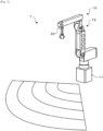
- Fig. 1 is a schematic configuration diagram of robot system 1 of the present embodiment.
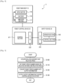
- Fig. 2 is a block diagram illustrating an electrical connection relationship among robot main body 10, robot control device 20, and safety device 30.
- robot system 1 of the present embodiment includes robot main body 10, robot control device 20 that controls the operation of robot main body 10, and safety device 30 for a robot capable of detecting an interfering object around robot main body 10.
- Robot main body 10 is a working robot that performs a predetermined work, and examples thereof include a machining robot that machines a workpiece with a tool, a conveyance robot that grips a workpiece with a chuck and conveys the workpiece to another position, and an assembling robot that grips a workpiece with a chuck and assembles the workpiece to an object.
- Robot main body 10 includes base 11 and articulated arm 12 installed on base 11. Articulated arm 12 includes multiple arms connected in series to base 11 via joint shafts. Servo motor 15 that drives the corresponding joint shaft and encoder 16 (rotary encoder) that detects a rotation angle of corresponding servo motor 15 are disposed on each joint shaft. Robot main body 10 also includes amplifier section 17 that applies a driving current to each servo motor 15.
- Robot control device 20 includes control section 21 configured as a microprocessor including CPU, ROM, and RAM, and I/O port 22 for exchanging signals with control section 31 of safety device 30. Further, robot control device 20 outputs a control signal to amplifier section 17 of robot main body 10 and inputs a detection signal from encoder 16.
- control section 21 configured as a microprocessor including CPU, ROM, and RAM
- I/O port 22 for exchanging signals with control section 31 of safety device 30. Further, robot control device 20 outputs a control signal to amplifier section 17 of robot main body 10 and inputs a detection signal from encoder 16.
- Control section 21 of robot control device 20 controls the operation of robot main body 10 as follows. That is, control section 21 first sets a target angle of each joint shaft of articulated arm 12 from a target position and a target posture of an end effector thereof by inverse kinematics. Subsequently, control section 21 acquires a current angle of each joint shaft from corresponding encoder 16, and sets a speed command value of the joint shaft by feedback calculation (for example, proportional integral calculation or proportional integral derivative calculation) based on the difference between the target angle and the current angle for each joint shaft.
- feedback calculation for example, proportional integral calculation or proportional integral derivative calculation
- control section 21 sets a target speed that limits the speed of the speed command value by multiplying the speed command value by the speed override, which will be described later, that is determined in a range from a value 0 (0%) to a value 1 (100%).
- the target speed is the same value as the speed command value. That is, a robot speed is not limited.
- the speed override is 0.5 (50%)
- the target speed is half the speed command value.
- the target speed is the value 0 regardless of the speed command value. That is, robot main body 10 stops operating.
- control section 21 calculates a current speed from the current angle of the joint shaft acquired from encoder 16, and sets a torque command value to be output from servo motor 15 by feedback calculation (for example, proportional integral calculation or proportional integral derivative calculation) based on a difference between the calculated current speed and the target speed. Then, control section 21 outputs a control signal to corresponding amplifier section 17 so that the torque corresponding to the set torque command is output from servo motor 15.
- safety device 30 for a robot is attached to the end effector of articulated arm 12.
- Safety device 30 includes control section 31 configured as a microprocessor including CPU, ROM, and RAM, sensor section 32 that monitors surroundings, and I/O port 33 for exchanging signals with control section 21.
- sensor section 32 is configured as a radar sensor of a frequency modulation continuous wave (FMCW) system.
- Sensor section 32 includes a transmission antenna that transmits a transmission chirp, a reception antenna that receives a reflected wave from an object as a reception chirp, a mixer that mixes the transmission chirp and the reception chirp to generate an intermediate frequency signal (IF signal), a processing section that processes the IF signal to detect a relative distance L to the object and a relative speed V to the object, and the like.
- the transmission antenna transmits, as one frame, multiple transmission chirps that are modulated so that the frequency changes with the elapse of time and are separated from each other by a certain interval.
- the processing section includes an A/D converter that A/D-converts the IF signal generated by the mixer, a DSP that performs Fourier transform processing (FFT processing) on the A/D-converted IF signal, and the like.
- the DSP can calculate relative distance L to the object based on a peak frequency by performing FFT processing (distance FFT processing) on the IF signal in chirp units to acquire a frequency spectrum. Further, the DSP can calculate the relative speed V with respect to the object based on the peak angular frequency by performing FFT processing (speed FFT processing) on the data after the distance FFT processing in units of frames to acquire the peak of the angular frequency.
- Fig. 3 is a flowchart illustrating an example of information output processing executed by control section 31 (CPU) of safety device 30.
- control section 31 first acquires relative distance L and relative speed V between sensor section 32 and the interfering object from sensor section 32 (S100). Subsequently, control section 31 sets robot speed number N corresponding to the speed override based on a combination of relative distance L and relative speed V acquired (S110).
- S110 relative distance L and relative speed V acquired
- the setting of robot speed number N is performed by deriving corresponding robot speed number N from the table.
- robot speed number N is set such that the speed override decreases as relative distance L from sensor section 32 to the interfering object decreases, and the speed override decreases as relative speed V between sensor section 32 and the interfering object in a direction approaching robot main body 10 increases. Accordingly, the robot speed is limited to be greater as relative distance L from sensor section 32 to the interfering object decreases and as relative speed V between sensor section 32 and the interfering object in the direction approaching robot main body 10 increases.
- control section 31 converts the set robot speed number N into output information of a predetermined bit (S120).
- the output information represents the speed override (for example, five speed limit values of 0%, 25%, 50%, 75%, and 100%) by information of a predetermined bit (for example, 4 bits).
- the conversion of the output information is performed by deriving the corresponding output information from the table.
- Fig. 5 illustrates the relationship among the robot speed number, the speed override, and the output information.
- the relationship between the combination of relative distance L and relative speed V and the speed override can be appropriately changed by connecting a computer to safety device 30 and operating the computer by the user. Then, control section 31 transmits the output information to robot control device 20 via I/O port 33 (S130), and ends the information output processing.
- Robot control device 20 receives output information from control section 31 of safety device 30 via I/O port 22 as a speed override, and controls servo motor 15 by setting a target speed whose speed is limited according to the speed override by multiplying the speed command value by the received speed override.
- Fig. 6 is a diagram illustrating the relationship between the relative distance between safety device 30 (sensor section 32) and the interfering object and the speed override.
- the speed override is set to 100%. That is, a robot speed is not limited.
- the speed override decreases as the interfering object approaches sensor section 32.
- the speed override decreases as the relative speed between sensor section 32 and the interfering object increases in the direction approaching sensor section 32. That is, the robot speed is limited to be greater as the interfering object approaches robot main body 10 and as the moving speed of the interfering object in the direction approaching robot main body 10 increases.
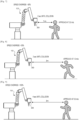
- the speed override is set to the same value when the time until the interfering object collides with robot main body 10 (sensor section 32) is the same regardless of the position within the detection range. Further, as illustrated in Fig.
- the speed override is set to 100% so that the robot speed is not limited. Accordingly, it is possible to stop robot main body 10 more reliably when the worker approaches robot main body 10 while suppressing unnecessary speed limitation of robot main body 10, and to ensure safety of the worker.
- sensor section 32 of the present embodiment corresponds to a detection section of the present disclosure
- control section 31 that executes S110 and S120 of the information output processing corresponds to a setting section
- control section 31 that executes S130 of the information output processing and I/O port 33 correspond to an output section.
- Robot main body 10 corresponds to a robot main body
- robot control device 20 corresponds to a robot control device.
- the speed override is transmitted to robot control device 20 by outputting output information of a predetermined bit to robot control device 20 via I/O port 33.
- safety device 30 may switch between the output information corresponding to the speed override and the output information corresponding to relative distance L via I/O port 33 and transmit the output information to robot control device 20.
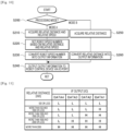
- Fig. 10 is a flowchart illustrating information output processing according to another embodiment.
- Control section 31 of safety device 30 determines whether a processing mode is mode A or mode B (S200). The processing mode is set in advance by an operator making an input using the input device.
- control section 31 acquires relative distance L and relative speed V between sensor section 32 and the interfering object, sets the robot speed number based on the combination of relative distance L and relative speed V, converts the robot speed number into output information, outputs the output information to robot control device 20 via I/O port 33 (S210 to S240), and ends the information output processing, similarly to S100 to S130 of the information output processing of Fig. 3 .
- control section 31 acquires relative distance L between sensor section 32 and the interfering object (S250), converts the acquired relative distance L into output information (S260), outputs the output information to robot control device 20 via I/O port 33 (S240), and ends the information output processing.
- the relationship between the relative speed L and the output information is illustrated in Fig. 11 . Accordingly, it is possible to satisfy both the specification of the robot that inputs the speed override and controls the robot speed and the specification of the robot that inputs the relative distance between sensor section 32 and the interfering object and controls the robot speed based on the relative distance.
- safety device 30 is attached to an end effector portion (distal end portion) of articulated arm 12 of robot main body 10, but may be attached to base 11 of robot main body 10.
- Safety device 30 is provided in the stationary robot, but may be provided in a self-propelled robot.
- the self-propelled robot may be a conveyance robot in addition to the arm robot including the articulated arm described above. For example, as illustrated in Fig.
- automatic exchange robot 110 which moves along mounting line 100 and exchanges feeders 102 with respect to component mounters 101 may be provided.
- safety device 30 When safety device 30 is provided in automatic exchange robot 110 and an interfering object is detected within a detection range, safety device 30 outputs output information corresponding to a combination of relative distance L and relative speed V to the interfering object to automatic exchange robot 110.
- Automatic exchange robot 110 multiplies the speed command value by a speed override based on the input output information, thereby traveling at a limited traveling speed corresponding to the speed override.
- the speed limit value of the robot speed is set based on the combination of the relative distance and the relative speed between the object within the detection range and the detection section, and the set speed limit value is output to the control device for a robot. Since the control device for a robot only needs to input the speed limit value from the safety device, the robot speed can be appropriately controlled based on the relative distance and the relative speed between the object and the detection section without complicating the interface between the control device and the safety device. As a result, it is possible to further improve safety while simplifying the system.
- the output section may output information of a predetermined bit as the speed limit value to the control device via the input/output port, and the setting section may select and set any one of multiple pieces of information to which different speed limit values are respectively assigned based on the combination of the relative distance and the relative speed detected by the detection section.
- the number of input/output ports can be reduced and the device can be simplified as compared with a case where the relative distance and the relative speed detected by the detection section are converted into information of predetermined bits and output to the control device for a robot.
- the speed limit value may be a speed override value by which a speed command value of the robot is to be multiplied. In this way, the robot can limit the robot speed only by multiplying the speed override.
- the output section may have the first mode in which the speed limit value set by the setting section is output to the control device, and a second mode in which a relative distance to an object detected by the detection section is output to the control device.
- the present disclosure is not limited to the form of the safety device for a robot, and may be a form of a robot system including the robot main body, the control device, and the safety device.
- the robot main body may be an arm robot including an arm.
- the robot main body may be an automatic exchange robot which moves on a predetermined traveling line and exchanges the feeders with respect to the component mounters in a mounting line provided with multiple component mounters which are arranged in a conveyance direction of a board and can collect components from the feeders and mount the components on the board.
- the present disclosure can be applied to manufacturing industry of a robot or a safety device and the like.
- robot system 10: robot main body, 11: base, 12: articulated arm, 15: servo motor, 16: encoder, 17: amplifier section, 20: robot control device, 21: control section, 22: I/O port, 30: safety device, 31: control section, 32: sensor section, 33: I/O port, 100: mounting line, 101: component mounter, 102: feeder, 110: automatic exchange robot
Landscapes
- Engineering & Computer Science (AREA)
- Mechanical Engineering (AREA)
- Robotics (AREA)
- General Engineering & Computer Science (AREA)
- Radar, Positioning & Navigation (AREA)
- Remote Sensing (AREA)
- Manipulator (AREA)
Abstract
Description
- The present description discloses a safety device for robots and a robot system.
- Conventionally, as a safety device for a robot of this type, there has been proposed a device in which a distance to an object present in a search area is measured by a detection device, a limit signal for limiting a maximum speed of the robot is generated according to the distance to the object, and the generated limit signal is transmitted to a robot controller (for example, see Patent Literature 1).
- Patent Literature 1:
JP-A-2016-209953 - When the object is moving so as to approach the robot, the time until the object reaches the robot is changed depending on the moving speed of the object, and thus, it is desirable to take this into consideration when controlling a robot speed. Meanwhile, when the moving speed of the object is also measured in addition to the distance to the object by the detection device and the measured value is transmitted to the robot controller, an interface between the safety device and the robot controller (control device) is complicated and the system is complicated.
- A main object of the present disclosure is to further improve safety while simplifying a system.
- The present disclosure employs the following means in order to achieve the main object described above.
- A safety device for a robot of the present disclosure is summarized as a safety device for a robot including a control device that controls a robot speed, the safety device including: a detection section capable of detecting an object present within a predetermined detection range, the detection section detecting a relative distance and a relative speed between the object within the detection range and the detection section; a setting section setting a speed limit value of the robot speed based on a combination of the relative distance and the relative speed detected by the detection section; and an output section outputting the speed limit value set by the setting section to the control device.
- In the safety device for a robot of the present disclosure, the speed limit value of the robot speed is set based on the combination of the relative distance and the relative speed between the object within the detection range and the detection section, and the set speed limit value is output to a control device of a robot. Since the control device for a robot only needs to input the speed limit value from the safety device, the robot speed can be appropriately controlled based on the relative distance and the relative speed between the object and the detection section without complicating the interface between the control device and the safety device. As a result, it is possible to further improve safety while simplifying the system.
- A robot system of the present disclosure includes: a robot main body; a robot control device configured to control a robot speed of the robot main body; and a safety device including a detection section capable of detecting an object present within a predetermined detection range, the detection section detecting a relative distance and a relative speed between the object within the detection range and the detection section, a setting section configured to set a speed limit value of the robot speed based on a combination of the relative distance and the relative speed detected by the detection section, and an output section configured to output the speed limit value set by the setting section to the robot control device.
- Since the robot system of the present disclosure includes the safety device of the present disclosure, it is possible to achieve the same effect as the safety device of the present disclosure, that is, the effect of further improving safety while simplifying the system.
-
-
Fig. 1 is a schematic configuration diagram of a robot system according to the present embodiment. -
Fig. 2 is a block diagram illustrating an electrical connection relationship among a robot main body, a robot control device, and a safety device. -
Fig. 3 is a flowchart illustrating an example of information output processing executed by a control section of the safety device. -
Fig. 4 is a diagram illustrating a relationship among a relative distance, a relative speed, and a robot speed number. -
Fig. 5 is a diagram illustrating a relationship among the robot speed number, a speed override, and output information. -
Fig. 6 is a diagram illustrating a relationship between the relative distance between the safety device and an interfering object and the speed override. -
Fig. 7 is a diagram illustrating a relationship between a moving speed of the interfering object, a time until collision with a robot main body, and the speed override. -
Fig. 8 is a diagram illustrating a relationship between the moving speed of the interfering object, the time until collision with the robot main body, and the speed override. -
Fig. 9 is a diagram illustrating a relationship between the moving speed of the interfering object, the time until collision with the robot main body, and the speed override. -
Fig. 10 is a flowchart illustrating information output processing according to another embodiment. -
Fig. 11 is a diagram illustrating a relationship between a relative distance and output information. -
Fig. 12 is a schematic configuration diagram of a robot system according to another embodiment. - Next, an embodiment of the present disclosure will be described with reference to the drawings.
-
Fig. 1 is a schematic configuration diagram ofrobot system 1 of the present embodiment.Fig. 2 is a block diagram illustrating an electrical connection relationship among robotmain body 10,robot control device 20, andsafety device 30. As illustrated,robot system 1 of the present embodiment includes robotmain body 10,robot control device 20 that controls the operation of robotmain body 10, andsafety device 30 for a robot capable of detecting an interfering object around robotmain body 10. - Robot
main body 10 is a working robot that performs a predetermined work, and examples thereof include a machining robot that machines a workpiece with a tool, a conveyance robot that grips a workpiece with a chuck and conveys the workpiece to another position, and an assembling robot that grips a workpiece with a chuck and assembles the workpiece to an object. - Robot
main body 10 includesbase 11 and articulatedarm 12 installed onbase 11.Articulated arm 12 includes multiple arms connected in series tobase 11 via joint shafts.Servo motor 15 that drives the corresponding joint shaft and encoder 16 (rotary encoder) that detects a rotation angle ofcorresponding servo motor 15 are disposed on each joint shaft. Robotmain body 10 also includesamplifier section 17 that applies a driving current to eachservo motor 15. -
Robot control device 20 includescontrol section 21 configured as a microprocessor including CPU, ROM, and RAM, and I/O port 22 for exchanging signals withcontrol section 31 ofsafety device 30. Further,robot control device 20 outputs a control signal toamplifier section 17 of robotmain body 10 and inputs a detection signal fromencoder 16. -
Control section 21 ofrobot control device 20 controls the operation of robotmain body 10 as follows. That is,control section 21 first sets a target angle of each joint shaft of articulatedarm 12 from a target position and a target posture of an end effector thereof by inverse kinematics. Subsequently,control section 21 acquires a current angle of each joint shaft fromcorresponding encoder 16, and sets a speed command value of the joint shaft by feedback calculation (for example, proportional integral calculation or proportional integral derivative calculation) based on the difference between the target angle and the current angle for each joint shaft. Next,control section 21 sets a target speed that limits the speed of the speed command value by multiplying the speed command value by the speed override, which will be described later, that is determined in a range from a value 0 (0%) to a value 1 (100%). For example, when the speed override is the value 1 (100%), the target speed is the same value as the speed command value. That is, a robot speed is not limited. When the speed override is 0.5 (50%), the target speed is half the speed command value. Further, when the speed override is the value 0 (0%), the target speed is thevalue 0 regardless of the speed command value. That is, robotmain body 10 stops operating. Subsequently,control section 21 calculates a current speed from the current angle of the joint shaft acquired fromencoder 16, and sets a torque command value to be output fromservo motor 15 by feedback calculation (for example, proportional integral calculation or proportional integral derivative calculation) based on a difference between the calculated current speed and the target speed. Then,control section 21 outputs a control signal tocorresponding amplifier section 17 so that the torque corresponding to the set torque command is output fromservo motor 15. - In the present embodiment,
safety device 30 for a robot is attached to the end effector of articulatedarm 12.Safety device 30 includescontrol section 31 configured as a microprocessor including CPU, ROM, and RAM,sensor section 32 that monitors surroundings, and I/O port 33 for exchanging signals withcontrol section 21. - In the present embodiment,
sensor section 32 is configured as a radar sensor of a frequency modulation continuous wave (FMCW) system.Sensor section 32 includes a transmission antenna that transmits a transmission chirp, a reception antenna that receives a reflected wave from an object as a reception chirp, a mixer that mixes the transmission chirp and the reception chirp to generate an intermediate frequency signal (IF signal), a processing section that processes the IF signal to detect a relative distance L to the object and a relative speed V to the object, and the like. The transmission antenna transmits, as one frame, multiple transmission chirps that are modulated so that the frequency changes with the elapse of time and are separated from each other by a certain interval. The processing section includes an A/D converter that A/D-converts the IF signal generated by the mixer, a DSP that performs Fourier transform processing (FFT processing) on the A/D-converted IF signal, and the like. The DSP can calculate relative distance L to the object based on a peak frequency by performing FFT processing (distance FFT processing) on the IF signal in chirp units to acquire a frequency spectrum. Further, the DSP can calculate the relative speed V with respect to the object based on the peak angular frequency by performing FFT processing (speed FFT processing) on the data after the distance FFT processing in units of frames to acquire the peak of the angular frequency. - Next, the operation of
safety device 30 of the present embodiment will be described.Fig. 3 is a flowchart illustrating an example of information output processing executed by control section 31 (CPU) ofsafety device 30. In the information output processing,control section 31 first acquires relative distance L and relative speed V betweensensor section 32 and the interfering object from sensor section 32 (S100). Subsequently,control section 31 sets robot speed number N corresponding to the speed override based on a combination of relative distance L and relative speed V acquired (S110). When a relationship between relative distance L, relative speed V, and robot speed number N is obtained in advance and stored as a table and relative distance L and relative speed V are given, the setting of robot speed number N is performed by deriving corresponding robot speed number N from the table.Fig. 4 illustrates the relationship among relative distance L, relative speed V, and robot speed number N. As illustrated, robot speed number N is set such that the speed override decreases as relative distance L fromsensor section 32 to the interfering object decreases, and the speed override decreases as relative speed V betweensensor section 32 and the interfering object in a direction approaching robotmain body 10 increases. Accordingly, the robot speed is limited to be greater as relative distance L fromsensor section 32 to the interfering object decreases and as relative speed V betweensensor section 32 and the interfering object in the direction approaching robotmain body 10 increases. - After setting robot speed number N,
control section 31 converts the set robot speed number N into output information of a predetermined bit (S120). Here, the output information represents the speed override (for example, five speed limit values of 0%, 25%, 50%, 75%, and 100%) by information of a predetermined bit (for example, 4 bits). When a relationship between robot speed number N and the output information is obtained in advance and stored as a table and robot speed number N is given, the conversion of the output information is performed by deriving the corresponding output information from the table.Fig. 5 illustrates the relationship among the robot speed number, the speed override, and the output information. The relationship between the combination of relative distance L and relative speed V and the speed override can be appropriately changed by connecting a computer tosafety device 30 and operating the computer by the user. Then,control section 31 transmits the output information torobot control device 20 via I/O port 33 (S130), and ends the information output processing.Robot control device 20 receives output information fromcontrol section 31 ofsafety device 30 via I/O port 22 as a speed override, and controlsservo motor 15 by setting a target speed whose speed is limited according to the speed override by multiplying the speed command value by the received speed override. -
Fig. 6 is a diagram illustrating the relationship between the relative distance between safety device 30 (sensor section 32) and the interfering object and the speed override. As illustrated, when there is no interfering object within a detection range (the relative distance betweensensor section 32 and the interfering object is up to 2000 mm) ofsensor section 32, that is, when the interfering object is not detected bysensor section 32, the speed override is set to 100%. That is, a robot speed is not limited. Meanwhile, when there is an interfering object within the detection range ofsensor section 32, that is, when the interfering object is detected bysensor section 32, the speed override decreases as the interfering object approachessensor section 32. Further, when the interfering object is moving, the speed override decreases as the relative speed betweensensor section 32 and the interfering object increases in the direction approachingsensor section 32. That is, the robot speed is limited to be greater as the interfering object approaches robotmain body 10 and as the moving speed of the interfering object in the direction approaching robotmain body 10 increases. In the present embodiment, as illustrated inFigs. 7 and 8 , when an interfering object (worker) is located within the detection range ofsensor section 32 and the interfering object is moving toward robot main body 10 (sensor section 32), the speed override is set to the same value when the time until the interfering object collides with robot main body 10 (sensor section 32) is the same regardless of the position within the detection range. Further, as illustrated inFig. 9 , even in a case where the interfering object is moving toward robot main body 10 (sensor section 32), when the moving speed of the interfering object is slow and there is a margin in time until the interfering object collides with robot main body 10 (sensor section 32), the speed override is set to 100% so that the robot speed is not limited. Accordingly, it is possible to stop robotmain body 10 more reliably when the worker approaches robotmain body 10 while suppressing unnecessary speed limitation of robotmain body 10, and to ensure safety of the worker. - Here, a correspondence relationship between main elements of the embodiment and main elements of the present disclosure described in the claims will be described. That is,
sensor section 32 of the present embodiment corresponds to a detection section of the present disclosure,control section 31 that executes S110 and S120 of the information output processing corresponds to a setting section, andcontrol section 31 that executes S130 of the information output processing and I/O port 33 correspond to an output section. Robotmain body 10 corresponds to a robot main body, androbot control device 20 corresponds to a robot control device. - The present disclosure is not limited in any way to the embodiment described above, and it is needless to say that the embodiment may be implemented in various aspects as long as it falls within a technical scope of the present disclosure.
- For example, in the above-described embodiment, the speed override is transmitted to
robot control device 20 by outputting output information of a predetermined bit torobot control device 20 via I/O port 33. However,safety device 30 may switch between the output information corresponding to the speed override and the output information corresponding to relative distance L via I/O port 33 and transmit the output information torobot control device 20.Fig. 10 is a flowchart illustrating information output processing according to another embodiment.Control section 31 ofsafety device 30 determines whether a processing mode is mode A or mode B (S200). The processing mode is set in advance by an operator making an input using the input device. When it is determined that the processing mode is mode A,control section 31 acquires relative distance L and relative speed V betweensensor section 32 and the interfering object, sets the robot speed number based on the combination of relative distance L and relative speed V, converts the robot speed number into output information, outputs the output information torobot control device 20 via I/O port 33 (S210 to S240), and ends the information output processing, similarly to S100 to S130 of the information output processing ofFig. 3 . Meanwhile, when it is determined that the processing mode is mode B,control section 31 acquires relative distance L betweensensor section 32 and the interfering object (S250), converts the acquired relative distance L into output information (S260), outputs the output information torobot control device 20 via I/O port 33 (S240), and ends the information output processing. The relationship between the relative speed L and the output information is illustrated inFig. 11 . Accordingly, it is possible to satisfy both the specification of the robot that inputs the speed override and controls the robot speed and the specification of the robot that inputs the relative distance betweensensor section 32 and the interfering object and controls the robot speed based on the relative distance. - In the above-described embodiment,
safety device 30 is attached to an end effector portion (distal end portion) of articulatedarm 12 of robotmain body 10, but may be attached to base 11 of robotmain body 10.Safety device 30 is provided in the stationary robot, but may be provided in a self-propelled robot. The self-propelled robot may be a conveyance robot in addition to the arm robot including the articulated arm described above. For example, as illustrated inFig. 12 , in mountingline 100 havingmultiple component mounter 101 which are arranged in a conveyance direction of a board, have a feeder table to whichfeeders 102 are attached and detached, and collect components fromfeeders 102 and mount the components on the board,automatic exchange robot 110 which moves along mountingline 100 andexchanges feeders 102 with respect tocomponent mounters 101 may be provided. Whensafety device 30 is provided inautomatic exchange robot 110 and an interfering object is detected within a detection range,safety device 30 outputs output information corresponding to a combination of relative distance L and relative speed V to the interfering object toautomatic exchange robot 110.Automatic exchange robot 110 multiplies the speed command value by a speed override based on the input output information, thereby traveling at a limited traveling speed corresponding to the speed override. - As described above, in the safety device for a robot of the present disclosure, the speed limit value of the robot speed is set based on the combination of the relative distance and the relative speed between the object within the detection range and the detection section, and the set speed limit value is output to the control device for a robot. Since the control device for a robot only needs to input the speed limit value from the safety device, the robot speed can be appropriately controlled based on the relative distance and the relative speed between the object and the detection section without complicating the interface between the control device and the safety device. As a result, it is possible to further improve safety while simplifying the system.
- In the safety device for a robot according to the present disclosure, the output section may output information of a predetermined bit as the speed limit value to the control device via the input/output port, and the setting section may select and set any one of multiple pieces of information to which different speed limit values are respectively assigned based on the combination of the relative distance and the relative speed detected by the detection section. In this case, the number of input/output ports can be reduced and the device can be simplified as compared with a case where the relative distance and the relative speed detected by the detection section are converted into information of predetermined bits and output to the control device for a robot.
- In the safety device for a robot according to the present disclosure, the speed limit value may be a speed override value by which a speed command value of the robot is to be multiplied. In this way, the robot can limit the robot speed only by multiplying the speed override.
- Further, in the safety device for a robot according to the present disclosure, the output section may have the first mode in which the speed limit value set by the setting section is output to the control device, and a second mode in which a relative distance to an object detected by the detection section is output to the control device. In this way, it is possible to satisfy both the specification of the robot that controls the robot speed by inputting the speed limit value and the specification of the robot that controls the robot speed based on the relative distance by inputting the relative distance between the detection section and the object.
- The present disclosure is not limited to the form of the safety device for a robot, and may be a form of a robot system including the robot main body, the control device, and the safety device. In this case, the robot main body may be an arm robot including an arm. Further, the robot main body may be an automatic exchange robot which moves on a predetermined traveling line and exchanges the feeders with respect to the component mounters in a mounting line provided with multiple component mounters which are arranged in a conveyance direction of a board and can collect components from the feeders and mount the components on the board.
- The present disclosure can be applied to manufacturing industry of a robot or a safety device and the like.
- 1: robot system, 10: robot main body, 11: base, 12: articulated arm, 15: servo motor, 16: encoder, 17: amplifier section, 20: robot control device, 21: control section, 22: I/O port, 30: safety device, 31: control section, 32: sensor section, 33: I/O port, 100: mounting line, 101: component mounter, 102: feeder, 110: automatic exchange robot
Claims (7)
- A safety device for a robot including a control device configured to control a robot speed, the safety device comprising:a detection section configured to detect an object present within a predetermined detection range, the detection section detecting a relative distance and a relative speed between the object within the detection range and the detection section;a setting section configured to set a speed limit value of the robot speed based on a combination of the relative distance and the relative speed detected by the detection section; andan output section configured to output the speed limit value set by the setting section to the control device.
- The safety device for a robot according to Claim 1, whereinthe output section outputs information of a predetermined bit as the speed limit value to the control device via an input/output port, andthe setting section selects and sets any one of multiple pieces of information to which different speed limit values are respectively assigned based on the combination of the relative distance and the relative speed detected by the detection section.
- The safety device for a robot according to Claim 1 or 2, wherein the speed limit value is a speed override value by which a speed command value of the robot is to be multiplied.
- The safety device for a robot according to any one of Claims 1 to 3, wherein the output section has a first mode in which the speed limit value set by the setting section is output to the control device and a second mode in which the relative distance to the object detected by the detection section is output to the control device.
- A robot system comprising:a robot main body;a robot control device configured to control a robot speed of the robot main body; anda safety device including a detection section configured to detect an object present within a predetermined detection range, the detection section detecting a relative distance and a relative speed between the object within the detection range and the detection section, a setting section configured to set a speed limit value of the robot speed based on a combination of the relative distance and the relative speed detected by the detection section, and an output section configured to output the speed limit value set by the setting section to the robot control device.
- The robot system according to Claim 5, wherein the robot main body is an arm robot including an arm.
- The robot system according to Claim 5, wherein the robot main body is an automatic exchange robot which moves on a predetermined traveling line and exchanges the feeders with respect to the component mounters in a mounting line provided with multiple component mounters arranged in a conveyance direction of a board and configured to collect components from feeders and mount the components on the board.
Applications Claiming Priority (1)
| Application Number | Priority Date | Filing Date | Title |
|---|---|---|---|
| PCT/JP2022/000624 WO2023135664A1 (en) | 2022-01-12 | 2022-01-12 | Safety device for robots and robot system |
Publications (2)
| Publication Number | Publication Date |
|---|---|
| EP4464475A1 true EP4464475A1 (en) | 2024-11-20 |
| EP4464475A4 EP4464475A4 (en) | 2025-03-12 |
Family
ID=87278597
Family Applications (1)
| Application Number | Title | Priority Date | Filing Date |
|---|---|---|---|
| EP22920190.0A Pending EP4464475A4 (en) | 2022-01-12 | 2022-01-12 | SAFETY DEVICE FOR ROBOT AND ROBOT SYSTEM |
Country Status (3)
| Country | Link |
|---|---|
| EP (1) | EP4464475A4 (en) |
| JP (1) | JP7846138B2 (en) |
| WO (1) | WO2023135664A1 (en) |
Family Cites Families (9)
| Publication number | Priority date | Publication date | Assignee | Title |
|---|---|---|---|---|
| EP1535706A1 (en) * | 2002-07-18 | 2005-06-01 | Kabushiki Kaisha Yaskawa Denki | Robot controller and robot system |
| EP2364243B1 (en) * | 2008-12-03 | 2012-08-01 | ABB Research Ltd. | A robot safety system and a method |
| DE112016000264T5 (en) * | 2015-03-04 | 2017-09-28 | Abb Ag | Safety control system and method for operating a safety control system |
| JP2016193473A (en) | 2015-04-01 | 2016-11-17 | 富士電機株式会社 | Drive control device and safety control system |
| JP6481495B2 (en) | 2015-05-08 | 2019-03-13 | 株式会社デンソーウェーブ | Robot safety device |
| DE102016007519A1 (en) * | 2016-06-20 | 2017-12-21 | Kuka Roboter Gmbh | Monitoring a system with at least one robot |
| CN110431930B (en) | 2017-03-30 | 2020-12-08 | 株式会社富士 | Installation system and notification control device |
| EP3909726B1 (en) * | 2019-01-11 | 2026-04-22 | Fuji Corporation | Control device, workpiece working apparatus, workpiece working system, and control method |
| JP7370746B2 (en) | 2019-07-09 | 2023-10-30 | 株式会社東芝 | Cooperative control device and robot system |
-
2022
- 2022-01-12 EP EP22920190.0A patent/EP4464475A4/en active Pending
- 2022-01-12 WO PCT/JP2022/000624 patent/WO2023135664A1/en not_active Ceased
- 2022-01-12 JP JP2023573682A patent/JP7846138B2/en active Active
Also Published As
| Publication number | Publication date |
|---|---|
| WO2023135664A1 (en) | 2023-07-20 |
| JP7846138B2 (en) | 2026-04-14 |
| EP4464475A4 (en) | 2025-03-12 |
| JPWO2023135664A1 (en) | 2023-07-20 |
Similar Documents
| Publication | Publication Date | Title |
|---|---|---|
| KR890005033B1 (en) | Drive system for a movable apparatus | |
| US11904483B2 (en) | Work robot system | |
| US4969108A (en) | Vision seam tracking method and apparatus for a manipulator | |
| JP6364096B2 (en) | Robot system | |
| JP7296593B2 (en) | Encoder abnormality detection method, operation control device, robot and robot system | |
| JP2000190262A (en) | Robot control device | |
| CN111034027A (en) | Anomaly detection method for encoder | |
| EP0965417B1 (en) | Robot controlling system | |
| CN104070522A (en) | Method and device capable of automatically identifying and preventing collision for industrial robot | |
| CN108453733B (en) | Robot with feedback control function, motion control system, method and medium | |
| US20030235060A1 (en) | Motor driving controller | |
| CN110315558B (en) | Control device and control method for cooperative robot | |
| JP7846138B2 (en) | Robot safety devices and robotic systems | |
| JP7824401B2 (en) | Safety Devices and Robot Systems | |
| US8121711B2 (en) | System and method for controlling movement of a measurement machine | |
| EP3909726B1 (en) | Control device, workpiece working apparatus, workpiece working system, and control method | |
| RU2187426C2 (en) | Self-adaptive electric drive of robot | |
| US20210242813A1 (en) | Robot | |
| WO2025069273A1 (en) | Object detection method and robot system | |
| US12138811B2 (en) | Robot control device and direct teaching method for robot | |
| WO2025126289A1 (en) | Sensor device, object sensing method, and robot system | |
| JPH0724765A (en) | Correction data communication system among robots | |
| JP7173798B2 (en) | A robot controller that monitors variables in motion programs | |
| CN216180543U (en) | Wall slotting robot | |
| EP4067012B1 (en) | Method for controlling robot, robot system, and program for controlling robot |
Legal Events
| Date | Code | Title | Description |
|---|---|---|---|
| STAA | Information on the status of an ep patent application or granted ep patent |
Free format text: STATUS: THE INTERNATIONAL PUBLICATION HAS BEEN MADE |
|
| PUAI | Public reference made under article 153(3) epc to a published international application that has entered the european phase |
Free format text: ORIGINAL CODE: 0009012 |
|
| STAA | Information on the status of an ep patent application or granted ep patent |
Free format text: STATUS: REQUEST FOR EXAMINATION WAS MADE |
|
| 17P | Request for examination filed |
Effective date: 20240624 |
|
| AK | Designated contracting states |
Kind code of ref document: A1 Designated state(s): AL AT BE BG CH CY CZ DE DK EE ES FI FR GB GR HR HU IE IS IT LI LT LU LV MC MK MT NL NO PL PT RO RS SE SI SK SM TR |
|
| REG | Reference to a national code |
Ref country code: DE Ref legal event code: R079 Free format text: PREVIOUS MAIN CLASS: B25J0019060000 Ipc: B25J0009160000 |
|
| A4 | Supplementary search report drawn up and despatched |
Effective date: 20250210 |
|
| RIC1 | Information provided on ipc code assigned before grant |
Ipc: F16P 3/14 20060101ALI20250204BHEP Ipc: B25J 19/06 20060101ALI20250204BHEP Ipc: B25J 9/16 20060101AFI20250204BHEP |
|
| DAV | Request for validation of the european patent (deleted) | ||
| DAX | Request for extension of the european patent (deleted) |