EP4464470A1 - Suction module - Google Patents
Suction module Download PDFInfo
- Publication number
- EP4464470A1 EP4464470A1 EP23174271.9A EP23174271A EP4464470A1 EP 4464470 A1 EP4464470 A1 EP 4464470A1 EP 23174271 A EP23174271 A EP 23174271A EP 4464470 A1 EP4464470 A1 EP 4464470A1
- Authority
- EP
- European Patent Office
- Prior art keywords
- suction
- vacuum
- main body
- modules
- suction module
- Prior art date
- Legal status (The legal status is an assumption and is not a legal conclusion. Google has not performed a legal analysis and makes no representation as to the accuracy of the status listed.)
- Granted
Links
Images


Classifications
-
- B—PERFORMING OPERATIONS; TRANSPORTING
- B25—HAND TOOLS; PORTABLE POWER-DRIVEN TOOLS; MANIPULATORS
- B25J—MANIPULATORS; CHAMBERS PROVIDED WITH MANIPULATION DEVICES
- B25J15/00—Gripping heads and other end effectors
- B25J15/06—Gripping heads and other end effectors with vacuum or magnetic holding means
- B25J15/0616—Gripping heads and other end effectors with vacuum or magnetic holding means with vacuum
-
- B—PERFORMING OPERATIONS; TRANSPORTING
- B25—HAND TOOLS; PORTABLE POWER-DRIVEN TOOLS; MANIPULATORS
- B25J—MANIPULATORS; CHAMBERS PROVIDED WITH MANIPULATION DEVICES
- B25J15/00—Gripping heads and other end effectors
- B25J15/0052—Gripping heads and other end effectors multiple gripper units or multiple end effectors
- B25J15/0061—Gripping heads and other end effectors multiple gripper units or multiple end effectors mounted on a modular gripping structure
Definitions
- Suction holders such as for example vacuum lifting pads, are generally known and serve to lift an item or to mount an item to a surface.
- suction elements are used to temporarily fix a holder for electrical wires on a base plate or a table.
- a sufficient stability of the holder is required to withstand the weight of the wires and any tilting forces applied to the holder during assembly of the wire harness.
- the present disclosure provides a suction module comprising a main body with a suction cup, wherein the main body has a vacuum passage that establishes a communication between a first vacuum port and the suction cup, and that further establishes a communication with at least one further vacuum port located at an outer surface of the main body.
- the suction element is designed as a suction module having a first vacuum port for applying a vacuum to the suction cup.
- the first vacuum port serves to apply a vacuum either by means of an external device such as a stationary vacuum source or a portable vacuum source, or by means of any other suitable device.
- the at least one further vacuum port that is located at an outer surface of the main body may either be closed and sealed, e.g.
- the at least one further suction port may be used to connect with a further suction module thereby increasing the adhering surface of the module assembly. Simultaneously, the upper surface area of such module assembly is increased which provides an enlarged surface area for fixing fixtures, such as holders for wires.
- Such cluster has an increased suction force and an increased area covering a ground surface wherein only a single vacuum source needs to be connected to the first vacuum port of one module.
- the further suction modules being part of the cluster can be connected with the first suction module by means of a connector.
- the further vacuum port of the suction module is located at an outer circumferential surface of the main body. This facilitates the connection to a further suction module since a rod-like or bar-like element can be used to connect two suction modules.
- At least two further vacuum ports are provided wherein all vacuum ports are equally spaced. In the case of three or more vacuum ports this leads to a star-like arrangement having a high degree of flexibility and stability.
- the first vacuum port is provided with a check valve. This allows to apply vacuum to the suction cup that is mounted to the suction module also after the vacuum source has been removed from the first vacuum port. For releasing vacuum from the suction module, it is merely necessary to open the check valve.
- an upper surface of the main body is provided with at least two identical fixtures for fixing a holding element.
- the holding element may for example be a fork holder for wires and the fixtures may have the form of a hole, a threaded hole, a bore or the like. If there are two or more fixtures provided on such module, there is a higher range of positions available for placing a holder thereby assuring a correct and versatile routing of a wire harness.
- the upper surface of the main body is provided with three identical fixtures that are equally spaced.
- Such design allows for a very high variability regardless of the use of a single suction module or of a cluster of suction modules.
- the main body has the shape of a circular cylinder with a flat upper cover surface.
- Such design has proven as advantageous with regard to handling, cleaning and forming a cluster of modules.
- the further vacuum port is sealed with a plug.
- the suction module can be used as a single module, however, after the plug is removed, the single module can be connected to at least one further suction module to form an assembly of suction modules.
- the main body is integrally made of one piece.
- the main body can for example be manufactured by means of an injection moulding or 3D-printing. In both cases it is merely necessary to mount the suction cup to the main body without further assembly steps being necessary.
- the vacuum ports are provided with a thread.
- the thread can form a part of the main body.
- threaded inserts such as metallic inserts, that are anchored in the vacuum ports.
- an assembly of at least two suction modules as described above wherein the suction modules are releasably interconnected by means of at least one connector that provides a communication passage between the vacuum passages of all suction modules.
- this provides the advantage that only one single vacuum source needs to be connected to the first vacuum port of a first suction module. If vacuum is applied, the vacuum passages of the vacuum modules and the communication passage of the connector allow for a distribution of the applied vacuum to the suction cups of all modules. Of course, it will be necessary to close and seal any open vacuum port that has no check valve or no connector.
- the suction cups of all suction modules are arranged coplanar.
- the connector has the shape of a straight rod, or has at least three coplanar arms with respectively two adjacent arms including the same angle.
- Such connector provides a cluster of two, three, four or more suction modules in a symmetrical design for good handling and stability properties.
- a distance between two suction modules equals about 80 - 120 % of a diameter of the connecting element.
- the suction modules are placed relatively closely to each other which improves the stability of the assembly.
- the assembly comprises a platform interconnecting the suction modules of the assembly wherein the platform is fixed in fixtures of the suction modules and has fixtures for fixing a holding element.
- Fig. 1 depicts a suction module 10 comprising a main body 12 with a suction cup 14.
- the main body 12 of this embodiment has the shape of a circular cylinder with a flat upper cover surface. It is noted that for illustrative purposes only, the flat upper cover surface of the suction module is omitted in all Figures.
- the main body 12 has a vacuum passage 16 ( Fig. 4 ) that establishes a communication between a first vacuum port 18, located at an outer circumferential surface 15 of the main body 12, and an interior space 17 ( Fig. 4 ) of a suction cup 14 which is mounted to the main body 12, e.g. by means of screws 20.
- the vacuum passage 16 further establishes a communication with a further vacuum port 22 also located at an outer circumferential surface 15 of the main body 12.
- a check valve 22 is inserted in the first vacuum port 18.
- vacuum e.g. by means of a vacuum gun 24 ( Fig. 6 )
- Fig. 4 shows the check valve 22 as a solid body for illustrative purposes only.
- the further vacuum port 19 and the fist vacuum port 18 include an angle of 120° and the further vacuum port 19 is closed and sealed with a plug (not shown in the drawings).
- Both vacuum ports 18, 19 are provided with a thread 24, 26 such that the check valve 22 and the plug can be screwed into the respective port.
- the ports can be provided with a threaded insert.
- the upper cover surface (that is not shown in the drawings) of the main body 12 is provided with a plurality of identical fixtures 30, 32, 34 for fixing a holding element such as a holder or a holding fork.
- the holding element can be inserted or screwed into the fixtures 30, 32, 34 that are designed as a bore, threaded bore or the like.
- the drawings show that the illustrated embodiment has three identical fixtures that are equally spaced thereby forming the corners of an isosceles triangle.
- the suction module shown in Figs. 1 to 4 can be used to mount a holder on a ground surface. After the holder is inserted in one of the fixtures 30, 32 and 34 and after the further vacuum port 19 has been closed and sealed, e.g. by means of a plug, the suction module can be placed on a ground surface at a desired location. Thereafter, vacuum can be applied to the vacuum passage 16 and thereby to the interior space 17 of the suction cup 14 wherein the vacuum passes through a central passage 36 in the bottom of suction cup 14. Thereby, the suction cup 14, which is made of a rubber-like, resilient material, is compressed and adheres to the ground surface. After this has been done, the vacuum source can be removed. and the vacuum is kept in the suction module by means of the check valve 22. For removing the module from the ground surface, the check valve 22 needs to be actuated to release the vacuum from the suction module 10.
- Fig. 5 shows an assembly of two suction modules 10 that are designed as described above wherein both suction modules 10 are releasably interconnected by means of a connector 40 that provides a communication passage 42 between the vacuum passages 16 of both suction modules 10.
- the connector 40 is designed as a cylindrical, rod-shaped element with two threaded ends. Accordingly, one end of the connector 40 is threaded into the further vacuum port 19 of the vacuum module 10 having the check valve 22. The opposite end of the connector 40 is threaded into the first vacuum port 18 of the left vacuum module 10 shown in Fig. 5 .
- the further vacuum port 19 of the left vacuum module 10 is closed, e.g. by means of a plug (not shown).
- the assembly shown in Fig. 5 provides not only three fixtures but a total of six fixtures 30, 32, and 34 located at different spots.
- Fig. 6 illustrates a further assembly comprising a total of three vacuum modules 10 interconnected by means of a connector (not visible in Fig. 6 ), wherein this connector has three coplanar arms with respectively two adjacent arms including an angle of 120°. Further, the further vacuum ports 19 visible in Fig. 6 are again closed and sealed, e.g. with a plug (not shown).
- a platform 50 is fixed in respectively two fixtures of the three suction modules 10.
- the platform 50 is provided with pins at the lower surface of the platform that are inserted in the fixtures of the suction modules.
- a plurality of fixtures 52 is provided at an upper surface of the platform 50 and these fixtures may also be located between the suction modules 10.
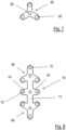
- Fig. 7 shows a plan view of a further embodiment of a platform 60 that is composed of three arms with respectively two arms including an angle of 120°.
- a platform 60 that is composed of three arms with respectively two arms including an angle of 120°.
- four fixtures 62 are provided with one fixture being located at the centre and three fixtures being located at the outer end of the three arms of the platform 60.
- the platform 60 can be mounted on a suction module and provides fixtures 62 not only at the outer circumference but also at the centre of the suction module.
- Fig. 8 shows a further embodiment of a platform 70 comprising a straight bar 71 that integrally connects at its outer ends two platforms 60 as shown in Fig. 7 .
- a straight bar 71 that integrally connects at its outer ends two platforms 60 as shown in Fig. 7 .
- two arms 74 and 76 extend in a transverse direction.
- a plurality of fixtures 72 are provided at an upper surface of the platform 70.
- each suction module may have more than two vacuum ports or may have a different shape and form.
Landscapes
- Engineering & Computer Science (AREA)
- Robotics (AREA)
- Mechanical Engineering (AREA)
- Hooks, Suction Cups, And Attachment By Adhesive Means (AREA)
- Manipulator (AREA)
Abstract
Description
- Suction holders, such as for example vacuum lifting pads, are generally known and serve to lift an item or to mount an item to a surface. In the field of the manufacture of a wire harness, suction elements are used to temporarily fix a holder for electrical wires on a base plate or a table. When developing and manufacturing a wire harness it is necessary to assure a proper adhesion of the suction element on the table for a sustainable time. Further, a sufficient stability of the holder is required to withstand the weight of the wires and any tilting forces applied to the holder during assembly of the wire harness.
- Accordingly, there is a need to provide a versatile suction element that is able to adhere to a ground surface for a long period of time with sufficient stability even if tilting forces are applied to the suction element.
- The present disclosure provides a suction module comprising a main body with a suction cup, wherein the main body has a vacuum passage that establishes a communication between a first vacuum port and the suction cup, and that further establishes a communication with at least one further vacuum port located at an outer surface of the main body. According to the first aspect, the suction element is designed as a suction module having a first vacuum port for applying a vacuum to the suction cup. The first vacuum port serves to apply a vacuum either by means of an external device such as a stationary vacuum source or a portable vacuum source, or by means of any other suitable device. The at least one further vacuum port that is located at an outer surface of the main body may either be closed and sealed, e.g. with a plug, to use such module as a stand-alone device. Alternatively, the at least one further suction port may be used to connect with a further suction module thereby increasing the adhering surface of the module assembly. Simultaneously, the upper surface area of such module assembly is increased which provides an enlarged surface area for fixing fixtures, such as holders for wires.
- With a plurality of suction modules as described above, it is possible to make a cluster of suction modules in a desired size and shape. Such cluster has an increased suction force and an increased area covering a ground surface wherein only a single vacuum source needs to be connected to the first vacuum port of one module. The further suction modules being part of the cluster can be connected with the first suction module by means of a connector.
- Advantageous embodiments are disclosed in the specification, the subclaims and the drawings.
- According to a first embodiment, the further vacuum port of the suction module is located at an outer circumferential surface of the main body. This facilitates the connection to a further suction module since a rod-like or bar-like element can be used to connect two suction modules.
- According to a further embodiment, at least two further vacuum ports are provided wherein all vacuum ports are equally spaced. In the case of three or more vacuum ports this leads to a star-like arrangement having a high degree of flexibility and stability.
- According to a further embodiment, the first vacuum port is provided with a check valve. This allows to apply vacuum to the suction cup that is mounted to the suction module also after the vacuum source has been removed from the first vacuum port. For releasing vacuum from the suction module, it is merely necessary to open the check valve.
- According to a further embodiment, an upper surface of the main body is provided with at least two identical fixtures for fixing a holding element. The holding element may for example be a fork holder for wires and the fixtures may have the form of a hole, a threaded hole, a bore or the like. If there are two or more fixtures provided on such module, there is a higher range of positions available for placing a holder thereby assuring a correct and versatile routing of a wire harness.
- According to a further embodiment, the upper surface of the main body is provided with three identical fixtures that are equally spaced. Such design allows for a very high variability regardless of the use of a single suction module or of a cluster of suction modules.
- According to a further embodiment, the main body has the shape of a circular cylinder with a flat upper cover surface. Such design has proven as advantageous with regard to handling, cleaning and forming a cluster of modules.
- According to a further embodiment, the further vacuum port is sealed with a plug. In this embodiment, the suction module can be used as a single module, however, after the plug is removed, the single module can be connected to at least one further suction module to form an assembly of suction modules.
- According to a further embodiment, the main body is integrally made of one piece. The main body can for example be manufactured by means of an injection moulding or 3D-printing. In both cases it is merely necessary to mount the suction cup to the main body without further assembly steps being necessary.
- According to a further embodiment, the vacuum ports are provided with a thread. The thread can form a part of the main body. Alternatively, it is possible to provide threaded inserts, such as metallic inserts, that are anchored in the vacuum ports.
- According to a further aspect of this disclosure, an assembly of at least two suction modules as described above is provided, wherein the suction modules are releasably interconnected by means of at least one connector that provides a communication passage between the vacuum passages of all suction modules. As described above, this provides the advantage that only one single vacuum source needs to be connected to the first vacuum port of a first suction module. If vacuum is applied, the vacuum passages of the vacuum modules and the communication passage of the connector allow for a distribution of the applied vacuum to the suction cups of all modules. Of course, it will be necessary to close and seal any open vacuum port that has no check valve or no connector.
- According to an embodiment, the suction cups of all suction modules are arranged coplanar.
- According to a further embodiment, the connector has the shape of a straight rod, or has at least three coplanar arms with respectively two adjacent arms including the same angle. Such connector provides a cluster of two, three, four or more suction modules in a symmetrical design for good handling and stability properties.
- According to a further embodiment, a distance between two suction modules equals about 80 - 120 % of a diameter of the connecting element. In this embodiment the suction modules are placed relatively closely to each other which improves the stability of the assembly.
- According to a further embodiment, the assembly comprises a platform interconnecting the suction modules of the assembly wherein the platform is fixed in fixtures of the suction modules and has fixtures for fixing a holding element. By providing the platform, not only the stability of the assembly can be increased, but is also possible to provide fixtures at a location between adjacent suction modules to provide more options for mounting a fixture at a desired location.
- Exemplary embodiments and functions of the present disclosure are described with reference to the following drawings, showing schematically in:
-
Fig. 1 A perspective view of a suction module; -
Fig. 2 A top view of the module ofFig. 1 ; -
Fig. 3 A side view of the module ofFig. 1 ; -
Fig. 4 A cross-section along the line A-A ofFig. 3 ; -
Fig. 5 An assembly of two suction modules interconnected by means of a connector; -
Fig. 6 An assembly of three suction modules interconnected by means of a connector (not shown) and a platform; -
Fig. 7 A platform; and -
Fig. 8 A further embodiment of a platform. -
Fig. 1 depicts asuction module 10 comprising amain body 12 with asuction cup 14. Themain body 12 of this embodiment has the shape of a circular cylinder with a flat upper cover surface. It is noted that for illustrative purposes only, the flat upper cover surface of the suction module is omitted in all Figures. - In the embodiment shown in the Figures, the
main body 12 has a vacuum passage 16 (Fig. 4 ) that establishes a communication between afirst vacuum port 18, located at an outercircumferential surface 15 of themain body 12, and an interior space 17 (Fig. 4 ) of asuction cup 14 which is mounted to themain body 12, e.g. by means ofscrews 20. Thevacuum passage 16 further establishes a communication with afurther vacuum port 22 also located at an outercircumferential surface 15 of themain body 12. - In order to apply a vacuum to the
vacuum passage 16 and to theinterior space 17 of the suction cup 14 acheck valve 22 is inserted in thefirst vacuum port 18. Thereby, it is possible to apply vacuum, e.g. by means of a vacuum gun 24 (Fig. 6 ), to theinterior space 17 of thesuction cup 14. It is noted thatFig. 4 shows thecheck valve 22 as a solid body for illustrative purposes only. - As illustrated in
Fig. 2 , thefurther vacuum port 19 and thefist vacuum port 18 include an angle of 120° and thefurther vacuum port 19 is closed and sealed with a plug (not shown in the drawings). Bothvacuum ports thread check valve 22 and the plug can be screwed into the respective port. Alternatively, the ports can be provided with a threaded insert. - The upper cover surface (that is not shown in the drawings) of the
main body 12 is provided with a plurality ofidentical fixtures fixtures - The suction module shown in
Figs. 1 to 4 can be used to mount a holder on a ground surface. After the holder is inserted in one of thefixtures further vacuum port 19 has been closed and sealed, e.g. by means of a plug, the suction module can be placed on a ground surface at a desired location. Thereafter, vacuum can be applied to thevacuum passage 16 and thereby to theinterior space 17 of thesuction cup 14 wherein the vacuum passes through acentral passage 36 in the bottom ofsuction cup 14. Thereby, thesuction cup 14, which is made of a rubber-like, resilient material, is compressed and adheres to the ground surface. After this has been done, the vacuum source can be removed. and the vacuum is kept in the suction module by means of thecheck valve 22. For removing the module from the ground surface, thecheck valve 22 needs to be actuated to release the vacuum from thesuction module 10. -
Fig. 5 shows an assembly of twosuction modules 10 that are designed as described above wherein bothsuction modules 10 are releasably interconnected by means of aconnector 40 that provides acommunication passage 42 between thevacuum passages 16 of bothsuction modules 10. Theconnector 40 is designed as a cylindrical, rod-shaped element with two threaded ends. Accordingly, one end of theconnector 40 is threaded into thefurther vacuum port 19 of thevacuum module 10 having thecheck valve 22. The opposite end of theconnector 40 is threaded into thefirst vacuum port 18 of theleft vacuum module 10 shown inFig. 5 . Thefurther vacuum port 19 of theleft vacuum module 10 is closed, e.g. by means of a plug (not shown). - Accordingly, the assembly shown in
Fig. 5 provides not only three fixtures but a total of sixfixtures -
Fig. 6 illustrates a further assembly comprising a total of threevacuum modules 10 interconnected by means of a connector (not visible inFig. 6 ), wherein this connector has three coplanar arms with respectively two adjacent arms including an angle of 120°. Further, thefurther vacuum ports 19 visible inFig. 6 are again closed and sealed, e.g. with a plug (not shown). - In the assembly of
Fig. 6 , aplatform 50 is fixed in respectively two fixtures of the threesuction modules 10. For example, theplatform 50 is provided with pins at the lower surface of the platform that are inserted in the fixtures of the suction modules. At an upper surface of the platform 50 a plurality offixtures 52 is provided and these fixtures may also be located between thesuction modules 10. - For adhering the assembly of suction modules of
Fig. 6 on a ground surface, it is merely necessary to apply vacuum to thecheck valve 22 in theport 18. The vacuum is communicated through thevacuum passage 16 of eachsuction module 10 and through the vacuum passage of the connector to apply vacuum to the suction cups of all three suction modules. -
Fig. 7 shows a plan view of a further embodiment of aplatform 60 that is composed of three arms with respectively two arms including an angle of 120°. At an upper surface of theplatform 60 fourfixtures 62 are provided with one fixture being located at the centre and three fixtures being located at the outer end of the three arms of theplatform 60. Theplatform 60 can be mounted on a suction module and providesfixtures 62 not only at the outer circumference but also at the centre of the suction module. -
Fig. 8 shows a further embodiment of aplatform 70 comprising astraight bar 71 that integrally connects at its outer ends twoplatforms 60 as shown inFig. 7 . At the centre of thebar 71 twoarms fixtures 72 are provided at an upper surface of theplatform 70. - It should be noted that the assembly as shown in
Fig. 5 and Fig. 6 and the platforms shown inFigs. 6 to 8 are merely exemplary and there is a large variety of different assemblies that may be put together with the suction module disclosed above. As a matter of cause, each suction module may have more than two vacuum ports or may have a different shape and form.
Claims (15)
- Suction module (10), said suction module comprising a main body (12) with a suction cup (14), wherein the main body (12) has a vacuum passage (16) that establishes a communication between a first vacuum port (18) and the suction cup (14), and that further establishes a communication with at least one further vacuum port (19) located at an outer surface (15) of the main body (12).
- Suction module according to claim 1, wherein the further vacuum port (19) is located at an outer circumferential surface (15) of the main body (12).
- Suction module according to any one of the preceding claims, wherein at least two further vacuum ports (19) are provided, wherein all vacuum ports (18, 19) are equally spaced.
- Suction module according to any one of the preceding claims, wherein the first vacuum port (18) is provided with a check valve (22).
- Suction module according to any one of the preceding claims, wherein an upper cover surface of the main body (12) is provided with at least two identical fixtures (30, 32, 34) for fixing a holding element.
- Suction module according to claim 5, wherein the upper cover surface of the main body (12) is provided with three identical fixtures (30, 32, 34) that are equally spaced.
- Suction module according to any one of the preceding claims, wherein the main body (12) has the shape of a circular cylinder with a flat upper cover surface.
- Suction module according to any one of the preceding claims, wherein the further vacuum port (19) is sealed with a plug.
- Suction module according to any one of the preceding claims, wherein the main body (12) is integrally made of one piece.
- Suction module according to any one of the preceding claims, wherein the vacuum ports (18, 19) are provided with a thread (24, 26).
- An assembly of at least two suction modules (10) according to any one of the preceding claims, wherein the suction modules (10) are releasably interconnected by means of at least one connector (40) that provides a communication passage (42) between the vacuum passages (16) of all suction modules (10).
- Assembly according to claim 11, wherein the suction cups (14) of all suction modules (10) are arranged coplanar.
- Assembly according to claim 11 or 12, wherein the connector (40) has the shape of a straight rod, or has at least three coplanar arms with respectively two adjacent arms including the same angle.
- Assembly according to any one of claims 11 to 13, wherein a distance between two suction modules equals about 80 - 120% of a diameter of the connector.
- Assembly according to any one of claims 11 to 14, comprising a platform (50, 60, 70) interconnecting the suction modules (10), wherein the platform (50, 60, 70) is fixed in fixtures (30, 32, 34) of the suction modules (10) and has fixtures (52, 62, 72) for fixing a holding element.
Priority Applications (1)
| Application Number | Priority Date | Filing Date | Title |
|---|---|---|---|
| EP23174271.9A EP4464470B1 (en) | 2023-05-19 | 2023-05-19 | Suction module |
Applications Claiming Priority (1)
| Application Number | Priority Date | Filing Date | Title |
|---|---|---|---|
| EP23174271.9A EP4464470B1 (en) | 2023-05-19 | 2023-05-19 | Suction module |
Publications (2)
| Publication Number | Publication Date |
|---|---|
| EP4464470A1 true EP4464470A1 (en) | 2024-11-20 |
| EP4464470B1 EP4464470B1 (en) | 2025-05-07 |
Family
ID=86469409
Family Applications (1)
| Application Number | Title | Priority Date | Filing Date |
|---|---|---|---|
| EP23174271.9A Active EP4464470B1 (en) | 2023-05-19 | 2023-05-19 | Suction module |
Country Status (1)
| Country | Link |
|---|---|
| EP (1) | EP4464470B1 (en) |
Citations (4)
| Publication number | Priority date | Publication date | Assignee | Title |
|---|---|---|---|---|
| GB2554619A (en) * | 2015-05-26 | 2018-04-04 | Ishida Seisakusho | Component for attracting article |
| EP3869544A1 (en) * | 2020-02-19 | 2021-08-25 | SMC Corporation | Non-contact transport device |
| US11167428B2 (en) * | 2018-06-05 | 2021-11-09 | C.R.F. Societa Consortile Per Azioni | Suction-type gripping device |
| US20220184818A1 (en) * | 2019-03-31 | 2022-06-16 | Robotiq Inc. | Adjustable suction gripper |
-
2023
- 2023-05-19 EP EP23174271.9A patent/EP4464470B1/en active Active
Patent Citations (4)
| Publication number | Priority date | Publication date | Assignee | Title |
|---|---|---|---|---|
| GB2554619A (en) * | 2015-05-26 | 2018-04-04 | Ishida Seisakusho | Component for attracting article |
| US11167428B2 (en) * | 2018-06-05 | 2021-11-09 | C.R.F. Societa Consortile Per Azioni | Suction-type gripping device |
| US20220184818A1 (en) * | 2019-03-31 | 2022-06-16 | Robotiq Inc. | Adjustable suction gripper |
| EP3869544A1 (en) * | 2020-02-19 | 2021-08-25 | SMC Corporation | Non-contact transport device |
Also Published As
| Publication number | Publication date |
|---|---|
| EP4464470B1 (en) | 2025-05-07 |
Similar Documents
| Publication | Publication Date | Title |
|---|---|---|
| CN101994753B (en) | Clamps and apparatus and assembly using same | |
| US7080927B2 (en) | Modular lighting with blocks | |
| US8057248B1 (en) | Connector for mounting to a circuit board | |
| EP2112717B1 (en) | Connector Device | |
| US10215379B2 (en) | Lighting system | |
| US20170198892A1 (en) | Modular lighting system with a plurality of power bars | |
| EP3657915A3 (en) | Method of manufacturing a component carrier using a separation component, the component carrier, and a semi-finished product | |
| US20030077837A1 (en) | Manipulating micron scale items | |
| US10825748B2 (en) | Semiconductor package system and related methods | |
| EP4464470B1 (en) | Suction module | |
| JP2015508221A (en) | Lighting fixture module and lighting network having a plurality of lighting fixture modules | |
| US4643499A (en) | Component mounting apparatus | |
| CN101632165A (en) | Pickup for transport tool and transport tool with same | |
| US20220184818A1 (en) | Adjustable suction gripper | |
| CN105600708A (en) | Carton clamp arm with adjustable pivot block | |
| EP0980121A3 (en) | An adapter and socket assembly for a compact fluorescent lamp | |
| EP1789984A2 (en) | Structure for mounting chandelier arms | |
| KR20210095348A (en) | Magnetic collet with round contact surface | |
| SE529882C2 (en) | Apparatus and method for fixing a matrix plate during electroplating | |
| KR102294126B1 (en) | Magnetic collet with attachable structure | |
| CN114759378B (en) | Electrical connector with improved contact arrangement | |
| US12596020B2 (en) | Electrical end device, manufacturing method and adjustment method | |
| US3634571A (en) | Lead wire locating device | |
| CN215299988U (en) | Bunching layering tool | |
| KR101776632B1 (en) | Pick-up module for semiconductor chip |
Legal Events
| Date | Code | Title | Description |
|---|---|---|---|
| PUAI | Public reference made under article 153(3) epc to a published international application that has entered the european phase |
Free format text: ORIGINAL CODE: 0009012 |
|
| STAA | Information on the status of an ep patent application or granted ep patent |
Free format text: STATUS: THE APPLICATION HAS BEEN PUBLISHED |
|
| AK | Designated contracting states |
Kind code of ref document: A1 Designated state(s): AL AT BE BG CH CY CZ DE DK EE ES FI FR GB GR HR HU IE IS IT LI LT LU LV MC ME MK MT NL NO PL PT RO RS SE SI SK SM TR |
|
| STAA | Information on the status of an ep patent application or granted ep patent |
Free format text: STATUS: REQUEST FOR EXAMINATION WAS MADE |
|
| GRAP | Despatch of communication of intention to grant a patent |
Free format text: ORIGINAL CODE: EPIDOSNIGR1 |
|
| STAA | Information on the status of an ep patent application or granted ep patent |
Free format text: STATUS: GRANT OF PATENT IS INTENDED |
|
| 17P | Request for examination filed |
Effective date: 20241218 |
|
| INTG | Intention to grant announced |
Effective date: 20250120 |
|
| P01 | Opt-out of the competence of the unified patent court (upc) registered |
Free format text: CASE NUMBER: APP_3603/2025 Effective date: 20250122 |
|
| GRAS | Grant fee paid |
Free format text: ORIGINAL CODE: EPIDOSNIGR3 |
|
| GRAA | (expected) grant |
Free format text: ORIGINAL CODE: 0009210 |
|
| STAA | Information on the status of an ep patent application or granted ep patent |
Free format text: STATUS: THE PATENT HAS BEEN GRANTED |
|
| AK | Designated contracting states |
Kind code of ref document: B1 Designated state(s): AL AT BE BG CH CY CZ DE DK EE ES FI FR GB GR HR HU IE IS IT LI LT LU LV MC ME MK MT NL NO PL PT RO RS SE SI SK SM TR |
|
| REG | Reference to a national code |
Ref country code: GB Ref legal event code: FG4D |
|
| REG | Reference to a national code |
Ref country code: CH Ref legal event code: EP |
|
| REG | Reference to a national code |
Ref country code: DE Ref legal event code: R096 Ref document number: 602023003307 Country of ref document: DE |
|
| REG | Reference to a national code |
Ref country code: IE Ref legal event code: FG4D |
|
| PGFP | Annual fee paid to national office [announced via postgrant information from national office to epo] |
Ref country code: DE Payment date: 20250519 Year of fee payment: 3 |
|
| PGFP | Annual fee paid to national office [announced via postgrant information from national office to epo] |
Ref country code: FR Payment date: 20250513 Year of fee payment: 3 |
|
| PGFP | Annual fee paid to national office [announced via postgrant information from national office to epo] |
Ref country code: AT Payment date: 20250721 Year of fee payment: 3 |
|
| REG | Reference to a national code |
Ref country code: NL Ref legal event code: MP Effective date: 20250507 |
|
| PG25 | Lapsed in a contracting state [announced via postgrant information from national office to epo] |
Ref country code: FI Free format text: LAPSE BECAUSE OF FAILURE TO SUBMIT A TRANSLATION OF THE DESCRIPTION OR TO PAY THE FEE WITHIN THE PRESCRIBED TIME-LIMIT Effective date: 20250507 Ref country code: PT Free format text: LAPSE BECAUSE OF FAILURE TO SUBMIT A TRANSLATION OF THE DESCRIPTION OR TO PAY THE FEE WITHIN THE PRESCRIBED TIME-LIMIT Effective date: 20250908 Ref country code: ES Free format text: LAPSE BECAUSE OF FAILURE TO SUBMIT A TRANSLATION OF THE DESCRIPTION OR TO PAY THE FEE WITHIN THE PRESCRIBED TIME-LIMIT Effective date: 20250507 |
|
| REG | Reference to a national code |
Ref country code: LT Ref legal event code: MG9D |
|
| PG25 | Lapsed in a contracting state [announced via postgrant information from national office to epo] |
Ref country code: GR Free format text: LAPSE BECAUSE OF FAILURE TO SUBMIT A TRANSLATION OF THE DESCRIPTION OR TO PAY THE FEE WITHIN THE PRESCRIBED TIME-LIMIT Effective date: 20250808 Ref country code: NO Free format text: LAPSE BECAUSE OF FAILURE TO SUBMIT A TRANSLATION OF THE DESCRIPTION OR TO PAY THE FEE WITHIN THE PRESCRIBED TIME-LIMIT Effective date: 20250807 |
|
| PG25 | Lapsed in a contracting state [announced via postgrant information from national office to epo] |
Ref country code: NL Free format text: LAPSE BECAUSE OF FAILURE TO SUBMIT A TRANSLATION OF THE DESCRIPTION OR TO PAY THE FEE WITHIN THE PRESCRIBED TIME-LIMIT Effective date: 20250507 Ref country code: PL Free format text: LAPSE BECAUSE OF FAILURE TO SUBMIT A TRANSLATION OF THE DESCRIPTION OR TO PAY THE FEE WITHIN THE PRESCRIBED TIME-LIMIT Effective date: 20250507 |
|
| REG | Reference to a national code |
Ref country code: AT Ref legal event code: MK05 Ref document number: 1791978 Country of ref document: AT Kind code of ref document: T Effective date: 20250507 |
|
| PG25 | Lapsed in a contracting state [announced via postgrant information from national office to epo] |
Ref country code: BG Free format text: LAPSE BECAUSE OF FAILURE TO SUBMIT A TRANSLATION OF THE DESCRIPTION OR TO PAY THE FEE WITHIN THE PRESCRIBED TIME-LIMIT Effective date: 20250507 |
|
| PG25 | Lapsed in a contracting state [announced via postgrant information from national office to epo] |
Ref country code: HR Free format text: LAPSE BECAUSE OF FAILURE TO SUBMIT A TRANSLATION OF THE DESCRIPTION OR TO PAY THE FEE WITHIN THE PRESCRIBED TIME-LIMIT Effective date: 20250507 |
|
| PG25 | Lapsed in a contracting state [announced via postgrant information from national office to epo] |
Ref country code: AT Free format text: LAPSE BECAUSE OF FAILURE TO SUBMIT A TRANSLATION OF THE DESCRIPTION OR TO PAY THE FEE WITHIN THE PRESCRIBED TIME-LIMIT Effective date: 20250507 |
|
| PG25 | Lapsed in a contracting state [announced via postgrant information from national office to epo] |
Ref country code: RS Free format text: LAPSE BECAUSE OF FAILURE TO SUBMIT A TRANSLATION OF THE DESCRIPTION OR TO PAY THE FEE WITHIN THE PRESCRIBED TIME-LIMIT Effective date: 20250807 |
|
| PG25 | Lapsed in a contracting state [announced via postgrant information from national office to epo] |
Ref country code: IS Free format text: LAPSE BECAUSE OF FAILURE TO SUBMIT A TRANSLATION OF THE DESCRIPTION OR TO PAY THE FEE WITHIN THE PRESCRIBED TIME-LIMIT Effective date: 20250907 |
|
| PG25 | Lapsed in a contracting state [announced via postgrant information from national office to epo] |
Ref country code: LV Free format text: LAPSE BECAUSE OF FAILURE TO SUBMIT A TRANSLATION OF THE DESCRIPTION OR TO PAY THE FEE WITHIN THE PRESCRIBED TIME-LIMIT Effective date: 20250507 |
|
| PG25 | Lapsed in a contracting state [announced via postgrant information from national office to epo] |
Ref country code: DK Free format text: LAPSE BECAUSE OF FAILURE TO SUBMIT A TRANSLATION OF THE DESCRIPTION OR TO PAY THE FEE WITHIN THE PRESCRIBED TIME-LIMIT Effective date: 20250507 Ref country code: SM Free format text: LAPSE BECAUSE OF FAILURE TO SUBMIT A TRANSLATION OF THE DESCRIPTION OR TO PAY THE FEE WITHIN THE PRESCRIBED TIME-LIMIT Effective date: 20250507 |
|
| PG25 | Lapsed in a contracting state [announced via postgrant information from national office to epo] |
Ref country code: LU Free format text: LAPSE BECAUSE OF NON-PAYMENT OF DUE FEES Effective date: 20250519 |
|
| PG25 | Lapsed in a contracting state [announced via postgrant information from national office to epo] |
Ref country code: CZ Free format text: LAPSE BECAUSE OF FAILURE TO SUBMIT A TRANSLATION OF THE DESCRIPTION OR TO PAY THE FEE WITHIN THE PRESCRIBED TIME-LIMIT Effective date: 20250507 |
|
| PG25 | Lapsed in a contracting state [announced via postgrant information from national office to epo] |
Ref country code: EE Free format text: LAPSE BECAUSE OF FAILURE TO SUBMIT A TRANSLATION OF THE DESCRIPTION OR TO PAY THE FEE WITHIN THE PRESCRIBED TIME-LIMIT Effective date: 20250507 |
|
| PG25 | Lapsed in a contracting state [announced via postgrant information from national office to epo] |
Ref country code: SK Free format text: LAPSE BECAUSE OF FAILURE TO SUBMIT A TRANSLATION OF THE DESCRIPTION OR TO PAY THE FEE WITHIN THE PRESCRIBED TIME-LIMIT Effective date: 20250507 |
|
| PG25 | Lapsed in a contracting state [announced via postgrant information from national office to epo] |
Ref country code: IT Free format text: LAPSE BECAUSE OF FAILURE TO SUBMIT A TRANSLATION OF THE DESCRIPTION OR TO PAY THE FEE WITHIN THE PRESCRIBED TIME-LIMIT Effective date: 20250507 |
|
| REG | Reference to a national code |
Ref country code: BE Ref legal event code: MM Effective date: 20250531 |
|
| REG | Reference to a national code |
Ref country code: DE Ref legal event code: R097 Ref document number: 602023003307 Country of ref document: DE |
|
| PG25 | Lapsed in a contracting state [announced via postgrant information from national office to epo] |
Ref country code: MC Free format text: LAPSE BECAUSE OF FAILURE TO SUBMIT A TRANSLATION OF THE DESCRIPTION OR TO PAY THE FEE WITHIN THE PRESCRIBED TIME-LIMIT Effective date: 20250507 |
|
| PLBE | No opposition filed within time limit |
Free format text: ORIGINAL CODE: 0009261 |
|
| STAA | Information on the status of an ep patent application or granted ep patent |
Free format text: STATUS: NO OPPOSITION FILED WITHIN TIME LIMIT |
|
| PG25 | Lapsed in a contracting state [announced via postgrant information from national office to epo] |
Ref country code: RO Free format text: LAPSE BECAUSE OF FAILURE TO SUBMIT A TRANSLATION OF THE DESCRIPTION OR TO PAY THE FEE WITHIN THE PRESCRIBED TIME-LIMIT Effective date: 20250507 |
|
| REG | Reference to a national code |
Ref country code: CH Ref legal event code: L10 Free format text: ST27 STATUS EVENT CODE: U-0-0-L10-L00 (AS PROVIDED BY THE NATIONAL OFFICE) Effective date: 20260318 |
|
| PG25 | Lapsed in a contracting state [announced via postgrant information from national office to epo] |
Ref country code: IE Free format text: LAPSE BECAUSE OF NON-PAYMENT OF DUE FEES Effective date: 20250519 |
|
| 26N | No opposition filed |
Effective date: 20260210 |
|
| PG25 | Lapsed in a contracting state [announced via postgrant information from national office to epo] |
Ref country code: BE Free format text: LAPSE BECAUSE OF NON-PAYMENT OF DUE FEES Effective date: 20250531 |