EP4464287A1 - Knee brace for the treatment of gonarthrosis - Google Patents
Knee brace for the treatment of gonarthrosis Download PDFInfo
- Publication number
- EP4464287A1 EP4464287A1 EP24176243.4A EP24176243A EP4464287A1 EP 4464287 A1 EP4464287 A1 EP 4464287A1 EP 24176243 A EP24176243 A EP 24176243A EP 4464287 A1 EP4464287 A1 EP 4464287A1
- Authority
- EP
- European Patent Office
- Prior art keywords
- knee brace
- knee
- brace according
- pressure element
- belt
- Prior art date
- Legal status (The legal status is an assumption and is not a legal conclusion. Google has not performed a legal analysis and makes no representation as to the accuracy of the status listed.)
- Granted
Links
Images





Classifications
-
- A—HUMAN NECESSITIES
- A61—MEDICAL OR VETERINARY SCIENCE; HYGIENE
- A61F—FILTERS IMPLANTABLE INTO BLOOD VESSELS; PROSTHESES; DEVICES PROVIDING PATENCY TO, OR PREVENTING COLLAPSING OF, TUBULAR STRUCTURES OF THE BODY, e.g. STENTS; ORTHOPAEDIC, NURSING OR CONTRACEPTIVE DEVICES; FOMENTATION; TREATMENT OR PROTECTION OF EYES OR EARS; BANDAGES, DRESSINGS OR ABSORBENT PADS; FIRST-AID KITS
- A61F5/00—Orthopaedic methods or devices for non-surgical treatment of bones or joints; Nursing devices ; Anti-rape devices
- A61F5/01—Orthopaedic devices, e.g. long-term immobilising or pressure directing devices for treating broken or deformed bones such as splints, casts or braces
-
- A—HUMAN NECESSITIES
- A61—MEDICAL OR VETERINARY SCIENCE; HYGIENE
- A61F—FILTERS IMPLANTABLE INTO BLOOD VESSELS; PROSTHESES; DEVICES PROVIDING PATENCY TO, OR PREVENTING COLLAPSING OF, TUBULAR STRUCTURES OF THE BODY, e.g. STENTS; ORTHOPAEDIC, NURSING OR CONTRACEPTIVE DEVICES; FOMENTATION; TREATMENT OR PROTECTION OF EYES OR EARS; BANDAGES, DRESSINGS OR ABSORBENT PADS; FIRST-AID KITS
- A61F5/00—Orthopaedic methods or devices for non-surgical treatment of bones or joints; Nursing devices ; Anti-rape devices
- A61F5/01—Orthopaedic devices, e.g. long-term immobilising or pressure directing devices for treating broken or deformed bones such as splints, casts or braces
- A61F5/0102—Orthopaedic devices, e.g. long-term immobilising or pressure directing devices for treating broken or deformed bones such as splints, casts or braces specially adapted for correcting deformities of the limbs or for supporting them; Ortheses, e.g. with articulations
- A61F5/0104—Orthopaedic devices, e.g. long-term immobilising or pressure directing devices for treating broken or deformed bones such as splints, casts or braces specially adapted for correcting deformities of the limbs or for supporting them; Ortheses, e.g. with articulations without articulation
- A61F5/0106—Orthopaedic devices, e.g. long-term immobilising or pressure directing devices for treating broken or deformed bones such as splints, casts or braces specially adapted for correcting deformities of the limbs or for supporting them; Ortheses, e.g. with articulations without articulation for the knees
- A61F5/0109—Sleeve-like structures
-
- A—HUMAN NECESSITIES
- A61—MEDICAL OR VETERINARY SCIENCE; HYGIENE
- A61F—FILTERS IMPLANTABLE INTO BLOOD VESSELS; PROSTHESES; DEVICES PROVIDING PATENCY TO, OR PREVENTING COLLAPSING OF, TUBULAR STRUCTURES OF THE BODY, e.g. STENTS; ORTHOPAEDIC, NURSING OR CONTRACEPTIVE DEVICES; FOMENTATION; TREATMENT OR PROTECTION OF EYES OR EARS; BANDAGES, DRESSINGS OR ABSORBENT PADS; FIRST-AID KITS
- A61F5/00—Orthopaedic methods or devices for non-surgical treatment of bones or joints; Nursing devices ; Anti-rape devices
-
- A—HUMAN NECESSITIES
- A61—MEDICAL OR VETERINARY SCIENCE; HYGIENE
- A61F—FILTERS IMPLANTABLE INTO BLOOD VESSELS; PROSTHESES; DEVICES PROVIDING PATENCY TO, OR PREVENTING COLLAPSING OF, TUBULAR STRUCTURES OF THE BODY, e.g. STENTS; ORTHOPAEDIC, NURSING OR CONTRACEPTIVE DEVICES; FOMENTATION; TREATMENT OR PROTECTION OF EYES OR EARS; BANDAGES, DRESSINGS OR ABSORBENT PADS; FIRST-AID KITS
- A61F5/00—Orthopaedic methods or devices for non-surgical treatment of bones or joints; Nursing devices ; Anti-rape devices
- A61F5/01—Orthopaedic devices, e.g. long-term immobilising or pressure directing devices for treating broken or deformed bones such as splints, casts or braces
- A61F5/0102—Orthopaedic devices, e.g. long-term immobilising or pressure directing devices for treating broken or deformed bones such as splints, casts or braces specially adapted for correcting deformities of the limbs or for supporting them; Ortheses, e.g. with articulations
-
- A—HUMAN NECESSITIES
- A61—MEDICAL OR VETERINARY SCIENCE; HYGIENE
- A61F—FILTERS IMPLANTABLE INTO BLOOD VESSELS; PROSTHESES; DEVICES PROVIDING PATENCY TO, OR PREVENTING COLLAPSING OF, TUBULAR STRUCTURES OF THE BODY, e.g. STENTS; ORTHOPAEDIC, NURSING OR CONTRACEPTIVE DEVICES; FOMENTATION; TREATMENT OR PROTECTION OF EYES OR EARS; BANDAGES, DRESSINGS OR ABSORBENT PADS; FIRST-AID KITS
- A61F5/00—Orthopaedic methods or devices for non-surgical treatment of bones or joints; Nursing devices ; Anti-rape devices
- A61F5/01—Orthopaedic devices, e.g. long-term immobilising or pressure directing devices for treating broken or deformed bones such as splints, casts or braces
- A61F5/0102—Orthopaedic devices, e.g. long-term immobilising or pressure directing devices for treating broken or deformed bones such as splints, casts or braces specially adapted for correcting deformities of the limbs or for supporting them; Ortheses, e.g. with articulations
- A61F5/0104—Orthopaedic devices, e.g. long-term immobilising or pressure directing devices for treating broken or deformed bones such as splints, casts or braces specially adapted for correcting deformities of the limbs or for supporting them; Ortheses, e.g. with articulations without articulation
-
- A—HUMAN NECESSITIES
- A61—MEDICAL OR VETERINARY SCIENCE; HYGIENE
- A61F—FILTERS IMPLANTABLE INTO BLOOD VESSELS; PROSTHESES; DEVICES PROVIDING PATENCY TO, OR PREVENTING COLLAPSING OF, TUBULAR STRUCTURES OF THE BODY, e.g. STENTS; ORTHOPAEDIC, NURSING OR CONTRACEPTIVE DEVICES; FOMENTATION; TREATMENT OR PROTECTION OF EYES OR EARS; BANDAGES, DRESSINGS OR ABSORBENT PADS; FIRST-AID KITS
- A61F5/00—Orthopaedic methods or devices for non-surgical treatment of bones or joints; Nursing devices ; Anti-rape devices
- A61F5/01—Orthopaedic devices, e.g. long-term immobilising or pressure directing devices for treating broken or deformed bones such as splints, casts or braces
- A61F5/0102—Orthopaedic devices, e.g. long-term immobilising or pressure directing devices for treating broken or deformed bones such as splints, casts or braces specially adapted for correcting deformities of the limbs or for supporting them; Ortheses, e.g. with articulations
- A61F5/0104—Orthopaedic devices, e.g. long-term immobilising or pressure directing devices for treating broken or deformed bones such as splints, casts or braces specially adapted for correcting deformities of the limbs or for supporting them; Ortheses, e.g. with articulations without articulation
- A61F5/0106—Orthopaedic devices, e.g. long-term immobilising or pressure directing devices for treating broken or deformed bones such as splints, casts or braces specially adapted for correcting deformities of the limbs or for supporting them; Ortheses, e.g. with articulations without articulation for the knees
-
- A—HUMAN NECESSITIES
- A61—MEDICAL OR VETERINARY SCIENCE; HYGIENE
- A61F—FILTERS IMPLANTABLE INTO BLOOD VESSELS; PROSTHESES; DEVICES PROVIDING PATENCY TO, OR PREVENTING COLLAPSING OF, TUBULAR STRUCTURES OF THE BODY, e.g. STENTS; ORTHOPAEDIC, NURSING OR CONTRACEPTIVE DEVICES; FOMENTATION; TREATMENT OR PROTECTION OF EYES OR EARS; BANDAGES, DRESSINGS OR ABSORBENT PADS; FIRST-AID KITS
- A61F5/00—Orthopaedic methods or devices for non-surgical treatment of bones or joints; Nursing devices ; Anti-rape devices
- A61F5/01—Orthopaedic devices, e.g. long-term immobilising or pressure directing devices for treating broken or deformed bones such as splints, casts or braces
- A61F5/0102—Orthopaedic devices, e.g. long-term immobilising or pressure directing devices for treating broken or deformed bones such as splints, casts or braces specially adapted for correcting deformities of the limbs or for supporting them; Ortheses, e.g. with articulations
- A61F5/0123—Orthopaedic devices, e.g. long-term immobilising or pressure directing devices for treating broken or deformed bones such as splints, casts or braces specially adapted for correcting deformities of the limbs or for supporting them; Ortheses, e.g. with articulations for the knees
-
- A—HUMAN NECESSITIES
- A61—MEDICAL OR VETERINARY SCIENCE; HYGIENE
- A61F—FILTERS IMPLANTABLE INTO BLOOD VESSELS; PROSTHESES; DEVICES PROVIDING PATENCY TO, OR PREVENTING COLLAPSING OF, TUBULAR STRUCTURES OF THE BODY, e.g. STENTS; ORTHOPAEDIC, NURSING OR CONTRACEPTIVE DEVICES; FOMENTATION; TREATMENT OR PROTECTION OF EYES OR EARS; BANDAGES, DRESSINGS OR ABSORBENT PADS; FIRST-AID KITS
- A61F5/00—Orthopaedic methods or devices for non-surgical treatment of bones or joints; Nursing devices ; Anti-rape devices
- A61F5/01—Orthopaedic devices, e.g. long-term immobilising or pressure directing devices for treating broken or deformed bones such as splints, casts or braces
- A61F5/0102—Orthopaedic devices, e.g. long-term immobilising or pressure directing devices for treating broken or deformed bones such as splints, casts or braces specially adapted for correcting deformities of the limbs or for supporting them; Ortheses, e.g. with articulations
- A61F5/0123—Orthopaedic devices, e.g. long-term immobilising or pressure directing devices for treating broken or deformed bones such as splints, casts or braces specially adapted for correcting deformities of the limbs or for supporting them; Ortheses, e.g. with articulations for the knees
- A61F5/0125—Orthopaedic devices, e.g. long-term immobilising or pressure directing devices for treating broken or deformed bones such as splints, casts or braces specially adapted for correcting deformities of the limbs or for supporting them; Ortheses, e.g. with articulations for the knees the device articulating around a single pivot-point
Definitions
- knee braces for the treatment of gonarthrosis, capable of transmitting specific forces to the knee, are known.
- Knee braces acting on three push points, placed on opposite sides of the knee, so as to apply to the knee a load adapted to laterally "open" the sick side of the articulation subjected to cartilage deterioration, are known.
- the distribution of the push points on the knee provides that, on the healthy side of the articulation, there is a single push point substantially facing the articulation, while on the side of the knee wherein arthrosis appears, two push points are arranged, respectively placed above and below the articulation substantially at the same distance from the articulation.
- the knee braces known, for example from US 5,277,698 or EP 1 830 756 B1 , comprise an upper half-shell and a lower half-shell joined by an articulated rod, adapted to be placed on the sick side of the knee, and one or more belts spirally wound between the two half-shells with both the ends applied on the side of the knee brace bearing the rod.
- the single push point on the healthy side of the knee is determined by the contact point of the belts around the knee while the two opposite push points on the sick side of the knee are generated by the opposite ends of the articulated rod.
- the main drawbacks of the known three-points knee braces mainly consist of wearability, which raises criticalities in wearing the knee brace, adjusting the same and tensioning the belts with a suitable tightening force.
- An object of the present invention is to make a knee brace for the treatment of gonarthrosis which overcomes the drawbacks of the prior art.
- Another object of the present invention is to make a knee brace for the treatment of gonarthrosis which achieves an optimal tensioning in use.
- Another object of the present invention is to make a particularly simple and functional knee brace for the treatment of gonarthrosis, with low costs.
- a knee brace for the treatment of gonarthrosis overall indicated by 10 is shown, comprising a fabric base 11, an upper half-shell 12, a lower half-shell 13, both constrained to the fabric base 11, and a pressure element 17, 17' for laterally supporting a knee.
- the knee brace 10 is provided with a traction belt system, comprising at least one front belt 18', 18'' and at least one rear belt 19', 19'', connected to the upper and lower half-shells 12, 13 and to the pressure element 17, 17'.
- All the belts are adjustable in length, preferably by quick-engagement means of the hook-and-loop type (Velcro ⁇ ).
- the upper rear belt portion 19' and the lower rear belt portion 19'' are joined together to form a single rear belt returned in the pressure element 17'.
- the rod 14 shown in the figures is an articulated rod provided with a central joint, coinciding with an articulation point 14' of the knee brace, but it could be replaced by a flexible stick or other equivalent means, still capable of bending in the articulation point 14' of the knee brace.
- the object of the articulated rod 14 is substantially to keep the knee brace 10 stretched when the front 18 and rear 19 belts are placed in traction in operation and create a force which would tend to move the upper and lower ends of the brace closer.
- the knee brace 10 comprises a traction device 20 placed on one of the upper 12 or lower 13 half-shells or a traction device 20 placed on each of the half-shells 12, 13 as shown in the figures.
- the traction device 20 comprises a lever 21 and an inextensible cord 22, which is constrained at a first end to the lever 21 and at an opposite end to the front belt 18', 18'' and passes through a front return slot 23, placed on the upper 12 or lower 13 half-shell.
- the traction device 20 comprises a second inextensible cord 22', which is constrained at a first end to the same lever 21 and at an opposite end to the rear belt 19', 19'' and passes through a rear return slot 23' placed on the upper 12 or lower 13 half-shell.
- the distance between the articulation point 14' of the knee brace 10 and the front return slot 23 is greater than the distance between the articulation point 14' and the rear return slot 23'.
- arranging the front return slots 23 more spaced apart from each other along the height of the knee brace 10 than the rear return slots 23' advantageously contrasts the tendency of the rod 14 to remain permanently flexed.
- the half-shells 12, 13 preferably consist of two plastic parts, a flexible portion 112A, 113A, possibly covered with fabric and constrained, for example by stitching, to the fabric base 11, and a rigid plate 112B and 113B, bearing the traction device 20.
- the rigid plate 112B, 113B is removably fastened to the ends of the rod 14.
- the pressure element 17 comprises a ring 24, to which all the front and rear belts 18', 18'', 19', 19'' converge, and two stabilizing rods 25, placed above and below the ring 24 to stiffen the side portion of the fabric base 11 and preferably facilitate, by the presence of seats 26, the constraint by stitching the pressure element 17 to the fabric base 11.
- At least one front belt 18', 18'' of the knee brace 10 is provided at one of its ends with a quick-release device 27, 127.
- the constraint between the first and the second inextensible cords 22 and the upper front belt 18' and the lower front belt 18'', respectively, is of the releasable type, through the front quick-release device 27 in order to open the knee brace 10 at the front and wound it around the leg.
- the quick-release device 127 is placed between the upper front belt 18' and the lower front belt 18'', respectively, and the ring 24 of the pressure element 17.
- the quick-release device 127 comprises, in the example shown for exemplary and non-limiting purposes, a protruding knob 127a, made at the free end of the upper front belt 18' and the lower front belt 18'', adapted to engage with its own seat 127b made on the ring 24.
- the knee brace 10 With the only exception being the arrangement of the quick-release devices 127, which are placed between the upper 18' and lower 18" front belts and the ring 24 of the pressure element 17, for all the remaining details, the knee brace 10 according to the further embodiment of the invention identically recalls what is described for the first embodiment of figures 1-5 to which reference is integrally made.
- the upper front belt 18' and the lower front belt 18'' are connected to the first and the second inextensible cords 22 each by a front slot 28, within which they are returned.
- the arrangement of the quick-release devices 127 on the ring 24 advantageously allows to engage and release the belts using only one hand.
- the pressure element 17' is of the openable type, in order to allow to make the knee brace 10 openable at the front by a simple movement and to simultaneously close all the belts 18', 18'', 19', 19'' .
- the openable pressure element 17' comprises two complementary engaging portions 31', 31'' engageable to and separable from each other, each bearing slots 32', 32", for fastening the front and rear belts, respectively.
- a first engaging portion 31' bears a tooth 33' adapted to be diagonally inserted into an opening 34 of the opposite second engaging portion 31" and to be in abutment, on opposite faces thereof, against complementary portions 33" of the second engaging portion 31".
- the openable pressure element 17' provides in operation an appropriate safety with respect to the risk of accidental opening because the traction of the belts on the same occurs in the plane of the element itself or in the bandaging direction of the knee, while the movement required to open it is opposite, that is requires that the engaging portion 31' bearing the tooth 33' is raised upwards and then moved away from the knee.
- the engaging portion 31" is preferably fastened to the fabric base 11 in order to maintain a stable position and simplify the operations to wear the knee brace.
- the fabric base 11 can be indifferently made open at the front to be easily worn without being inserted from the foot, according to a first embodiment, or closed, as a tubular element, according to a further embodiment.
- the knee brace 10 when firstly applied on a patient, provides the adjustment of the length of the front adjusting belts 18, comprising the upper front belt 18' and the lower front belt 18'', and the rear ones 19, comprising the upper rear belt 19' and the lower rear belt 19'' by action on the Velcro ⁇ adjustment.
- the knee brace 10 After the first application of the knee brace 10, and for all the subsequent applications, the knee brace 10 is tightened by the lever traction devices 20, which put the belts 18 and 19 in traction.
- the quick-release devices 27 placed between the upper 18' and lower 18'' front belts and the traction device 20 In order to open and wear the knee brace without modifying the adjustments of the lengths of the belts, the quick-release devices 27 placed between the upper 18' and lower 18'' front belts and the traction device 20, the quick-release devices 127 placed between the upper 18' and lower 18" front belts and the pressure element 17 are used, or an action can be exerted on the complementary engaging portions 31', 31'' engageable to and separable from each other integrated in the openable pressure element 17'.
- the system of belts converging to the centre of the knee, on the side opposite to the rod, creates a push point which, together with the two push points at the upper and lower ends of the rod, assists in supporting the knee affected by unicompartmental gonarthrosis and in alleviating the pain created by "rubbing" the compartment affected by arthrosis.
- the support is medio-lateral or latero-medial depending on using a right or left knee brace on the right or left knee.
- the knee brace for the treatment of gonarthrosis being the object of the present invention has the advantage of allowing the user to quickly close the same, with little force and always alike, i.e., with a repeatable traction application.
- each lever preferentially applies tension both at the front and at the rear simultaneously.
- the used materials, as well as the size can be any depending on the technical requirements.
Landscapes
- Health & Medical Sciences (AREA)
- Nursing (AREA)
- Orthopedic Medicine & Surgery (AREA)
- Engineering & Computer Science (AREA)
- Biomedical Technology (AREA)
- Heart & Thoracic Surgery (AREA)
- Vascular Medicine (AREA)
- Life Sciences & Earth Sciences (AREA)
- Animal Behavior & Ethology (AREA)
- General Health & Medical Sciences (AREA)
- Public Health (AREA)
- Veterinary Medicine (AREA)
- Orthopedics, Nursing, And Contraception (AREA)
Abstract
Description
- The present invention refers to a knee brace for the treatment of gonarthrosis.
- Several different types of knee braces for the treatment of gonarthrosis, capable of transmitting specific forces to the knee, are known.
- In the case of unicompartmental gonarthrosis, there is a thinning of the cartilage of the knee particularly on a side thereof, which causes pain due to the direct contact between the bone condyles of femur and tibia, especially when the knee is under load. Hereinafter, such side of the articulation will be referred to as "sick side" and the opposite side will be referred to as "healthy side".
- Knee braces acting on three push points, placed on opposite sides of the knee, so as to apply to the knee a load adapted to laterally "open" the sick side of the articulation subjected to cartilage deterioration, are known. The distribution of the push points on the knee provides that, on the healthy side of the articulation, there is a single push point substantially facing the articulation, while on the side of the knee wherein arthrosis appears, two push points are arranged, respectively placed above and below the articulation substantially at the same distance from the articulation.
- The knee braces known, for example from
US 5,277,698 orEP 1 830 756 B1 , comprise an upper half-shell and a lower half-shell joined by an articulated rod, adapted to be placed on the sick side of the knee, and one or more belts spirally wound between the two half-shells with both the ends applied on the side of the knee brace bearing the rod. Indeed, the single push point on the healthy side of the knee is determined by the contact point of the belts around the knee while the two opposite push points on the sick side of the knee are generated by the opposite ends of the articulated rod. - The main drawbacks of the known three-points knee braces mainly consist of wearability, which raises criticalities in wearing the knee brace, adjusting the same and tensioning the belts with a suitable tightening force.
- The drawbacks with respect to wearability have an impact both on the comfort of the patient and on the effectiveness of the knee brace.
- An object of the present invention is to make a knee brace for the treatment of gonarthrosis which overcomes the drawbacks of the prior art.
- Another object of the present invention is to make a knee brace for the treatment of gonarthrosis which achieves an optimal tensioning in use.
- Another object of the present invention is to make a particularly simple and functional knee brace for the treatment of gonarthrosis, with low costs.
- These objects according to the present invention are achieved by making a knee brace for the treatment of gonarthrosis as set forth in claim 1.
- Further features are provided in the dependent claims.
- The features and advantages of a knee brace for the treatment of gonarthrosis according to the present invention will be more apparent from the following exemplary and non-limiting description referred to the attached schematic drawings, in which:
-
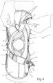
figure 1 is a front elevation view of the knee brace for the treatment of gonarthrosis according to a first embodiment of the present invention; -
figure 2 is a side view of the knee brace offigure 1 which shows the pressure element placed on the healthy side of the knee, wherein the upper and lower front belts are open for adjusting in length; -
figure 3 is an opposite side view of the knee brace offigure 1 which shows the articulated rod placed on the sick side of the knee; -
figure 4 shows the knee brace offigure 1 wherein the upper front belt is shown in the released position; -
figure 5 shows the knee brace offigure 1 wherein the upper and lower front belts are engaged, and the respective levers are open; -
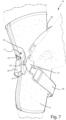
figure 6 shows a knee brace for the treatment of gonarthrosis according to a second embodiment of the present invention, wherein the pressure element is openable; -
figure 7 shows the knee brace offigure 6 wherein the pressure element is shown in the open position; -
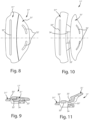
figures 8 and 9 are a plan view and a cross section of the openable pressure element placed in the closed position, respectively; -
figures 10 and 11 are a plan view and a cross section of the openable pressure element placed in the open position, respectively; -
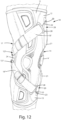
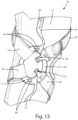
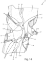
figures 12 to 15 show a knee brace for the treatment of gonarthrosis according to a further embodiment of the present invention. - With reference to the figures, a knee brace for the treatment of gonarthrosis overall indicated by 10 is shown, comprising a
fabric base 11, an upper half-shell 12, a lower half-shell 13, both constrained to thefabric base 11, and apressure element 17, 17' for laterally supporting a knee. - The
knee brace 10 is provided with a traction belt system, comprising at least one front belt 18', 18'' and at least onerear belt shells pressure element 17, 17'. - All the belts are adjustable in length, preferably by quick-engagement means of the hook-and-loop type (Velcro ©).
- According to the first embodiment shown in
figures 1 to 5 , theknee brace 10 comprises an upper front belt portion 18' and a lower front belt portion 18'', each constrained to opposite ends to the related upper 12 or lower 13 half-shell and to thepressure element 17, as well as an upperrear belt portion 19' and a lowerrear belt portion 19'', each constrained to opposite ends to the related upper 12 or lower 13 half-shell and to thepressure element 17. - In the second embodiment of the
knee brace 10, shown infigures 6 and7 , the upperrear belt portion 19' and the lowerrear belt portion 19'' are joined together to form a single rear belt returned in the pressure element 17'. - According to the invention, the
knee brace 10 further comprises arod 14, constrained to the two half-shells pressure element 17, 17'. - The
rod 14, shown in the figures, is an articulated rod provided with a central joint, coinciding with an articulation point 14' of the knee brace, but it could be replaced by a flexible stick or other equivalent means, still capable of bending in the articulation point 14' of the knee brace. The object of the articulatedrod 14 is substantially to keep theknee brace 10 stretched when thefront 18 and rear 19 belts are placed in traction in operation and create a force which would tend to move the upper and lower ends of the brace closer. - The
rod 14 could be inserted in a pocket inside thefabric base 11 or be constrained in a position external thereto, as shown in the figures. - According to the invention, the
knee brace 10 comprises atraction device 20 placed on one of the upper 12 or lower 13 half-shells or atraction device 20 placed on each of the half-shells - The
traction device 20 comprises alever 21 and aninextensible cord 22, which is constrained at a first end to thelever 21 and at an opposite end to the front belt 18', 18'' and passes through afront return slot 23, placed on the upper 12 or lower 13 half-shell. - Advantageously, according to a shown preferred embodiment, the
traction device 20 comprises a second inextensible cord 22', which is constrained at a first end to thesame lever 21 and at an opposite end to therear belt - Preferably, both the upper half-
shell 12 and the lower half-shell 13 of theknee brace 10 bear the describedtraction device 20. - Preferably, in the
traction device 20 the distance between the articulation point 14' of theknee brace 10 and thefront return slot 23 is greater than the distance between the articulation point 14' and the rear return slot 23'. Indeed, arranging thefront return slots 23 more spaced apart from each other along the height of theknee brace 10 than the rear return slots 23' advantageously contrasts the tendency of therod 14 to remain permanently flexed. - The half-
shells flexible portion fabric base 11, and arigid plate traction device 20. - In both the half-
shells rigid plate rod 14. - Preferably, the
rigid plates shells front 23 and rear 23' return slots. - According to the first embodiment of the invention, the
pressure element 17 comprises aring 24, to which all the front and rear belts 18', 18'', 19', 19'' converge, and two stabilizingrods 25, placed above and below thering 24 to stiffen the side portion of thefabric base 11 and preferably facilitate, by the presence ofseats 26, the constraint by stitching thepressure element 17 to thefabric base 11. - There can also be further seats 26' along the
ring 24 still for the constraint by stitching of thepressure element 17 with thefabric base 11. - According to the invention, at least one front belt 18', 18'' of the
knee brace 10 is provided at one of its ends with a quick-release device - Preferably, according to the first embodiment shown in
figures 1 to 5 , on the front side of theknee brace 10 the constraint between the first and the secondinextensible cords 22 and the upper front belt 18' and the lower front belt 18'', respectively, is of the releasable type, through the front quick-release device 27 in order to open theknee brace 10 at the front and wound it around the leg. - According to a further embodiment of the
knee brace 10 for the treatment of gonarthrosis according to the present invention, shown infigures 12 to 15 , the quick-release device 127 is placed between the upper front belt 18' and the lower front belt 18'', respectively, and thering 24 of thepressure element 17. - The quick-
release device 127 comprises, in the example shown for exemplary and non-limiting purposes, a protrudingknob 127a, made at the free end of the upper front belt 18' and the lower front belt 18'', adapted to engage with itsown seat 127b made on thering 24. - With the only exception being the arrangement of the quick-
release devices 127, which are placed between the upper 18' and lower 18" front belts and thering 24 of thepressure element 17, for all the remaining details, theknee brace 10 according to the further embodiment of the invention identically recalls what is described for the first embodiment offigures 1-5 to which reference is integrally made. - In the front part of the
knee brace 10 according to the invention shown infigures 12-15 the upper front belt 18' and the lower front belt 18'' are connected to the first and the secondinextensible cords 22 each by afront slot 28, within which they are returned. - The arrangement of the quick-
release devices 127 on thering 24 advantageously allows to engage and release the belts using only one hand. - According to the second embodiment of the
knee brace 10 shown infigures 6 to 10 , the pressure element 17' is of the openable type, in order to allow to make theknee brace 10 openable at the front by a simple movement and to simultaneously close all the belts 18', 18'', 19', 19'' . - The openable pressure element 17' comprises two complementary engaging portions 31', 31'' engageable to and separable from each other, each
bearing slots 32', 32", for fastening the front and rear belts, respectively. - A first engaging portion 31' bears a
tooth 33' adapted to be diagonally inserted into an opening 34 of the opposite secondengaging portion 31" and to be in abutment, on opposite faces thereof, againstcomplementary portions 33" of the secondengaging portion 31". - The openable pressure element 17' provides in operation an appropriate safety with respect to the risk of accidental opening because the traction of the belts on the same occurs in the plane of the element itself or in the bandaging direction of the knee, while the movement required to open it is opposite, that is requires that the engaging portion 31' bearing the
tooth 33' is raised upwards and then moved away from the knee. Theengaging portion 31" is preferably fastened to thefabric base 11 in order to maintain a stable position and simplify the operations to wear the knee brace. - In the
knee brace 10 according to the invention, thefabric base 11 can be indifferently made open at the front to be easily worn without being inserted from the foot, according to a first embodiment, or closed, as a tubular element, according to a further embodiment. - The constructive elements described for the different embodiments are equivalently interchangeable with each other.
- The
knee brace 10 according to the invention, when firstly applied on a patient, provides the adjustment of the length of the front adjustingbelts 18, comprising the upper front belt 18' and the lower front belt 18'', and therear ones 19, comprising the upperrear belt 19' and the lowerrear belt 19'' by action on the Velcro © adjustment. - After the first application of the
knee brace 10, and for all the subsequent applications, theknee brace 10 is tightened by thelever traction devices 20, which put thebelts - In order to open and wear the knee brace without modifying the adjustments of the lengths of the belts, the quick-
release devices 27 placed between the upper 18' and lower 18'' front belts and thetraction device 20, the quick-release devices 127 placed between the upper 18' and lower 18" front belts and thepressure element 17 are used, or an action can be exerted on the complementary engaging portions 31', 31'' engageable to and separable from each other integrated in the openable pressure element 17'. - The system of belts, converging to the centre of the knee, on the side opposite to the rod, creates a push point which, together with the two push points at the upper and lower ends of the rod, assists in supporting the knee affected by unicompartmental gonarthrosis and in alleviating the pain created by "rubbing" the compartment affected by arthrosis.
- The support is medio-lateral or latero-medial depending on using a right or left knee brace on the right or left knee.
- The knee brace for the treatment of gonarthrosis being the object of the present invention has the advantage of allowing the user to quickly close the same, with little force and always alike, i.e., with a repeatable traction application.
- Furthermore, advantageously each lever preferentially applies tension both at the front and at the rear simultaneously.
- In the knee brace for the treatment of gonarthrosis according to the invention, the used materials, as well as the size, can be any depending on the technical requirements.
Claims (12)
- Knee brace for the treatment of gonarthrosis comprising a fabric base (11), an upper half-shell (12) and a lower half-shell (13), constrained to the fabric base (11), a rod (14), constrained to the two half-shells (12, 13), as well as a pressure element (17, 17') for laterally supporting the knee against the side opposite to said rod (14), at least one front belt (18', 18'') and at least one rear belt (19', 19"), connected to said upper and lower half-shells (12, 13) and to said pressure element (17, 17'), characterized in that one of the upper or lower half-shells (12, 13) or both the upper and lower half-shells (12, 13) are provided with a traction device (20) comprising a lever (21) and an inextensible cord (22), which is constrained at one end to the lever (21) and at an opposite end to the front belt (18', 18'') and passes through a front return slot (23) placed on the half-shell (12, 13).
- Knee brace according to claim 2, characterized in that the traction device (20) comprises a second inextensible cord (22'), which is constrained at one end to the lever (21) and at an opposite end to the rear belt (19', 19") and passes through a rear return slot (23') placed on the half-shell (12, 13).
- Knee brace according to claim 2, characterized in that the distance between an articulation point (14') of the knee brace (10) and the front return slot (23) is greater than the distance between the articulation point (14') and the rear return slot (23').
- Knee brace according to any one of the preceding claims, characterized by comprising an upper front belt portion (18') and a lower front belt portion (18''), as well as comprising an upper rear belt portion (19') and a lower rear belt portion (19'').
- Knee brace according to claim 4, characterized in that said upper rear belt portion (19') and said lower rear belt portion (19'') are joined together and returned in a slot or ring (24, 32'') of the pressure element (17, 17').
- Knee brace according to claim 1, characterized in that at least one front belt (18', 18") is provided at one of its ends with a quick-release device (27,127).
- Knee brace according to claim 6, characterized in that the quick-release device (27) is placed at the front for the constraint between the inextensible cord (22) and the front belt (18', 18").
- Knee brace according to claim 6, characterized in that said quick-release device (127) is placed between the upper front belt (18', 18") and the pressure element (17).
- Knee brace according to any one of the preceding claims 1 to 7, characterized in that an openable pressure element (17') comprises two complementary engaging portions (31', 31'') engageable to and separable from each other, each bearing slots (32', 32'') for fastening the belts.
- Knee brace according to claim 9, characterized in that a first engaging portion (31') bears a tooth (33') adapted to be diagonally inserted into an opening (34) of an opposite second engaging portion (31'') and being in abutment against complementary portions (33'') of the second engaging portion (31").
- Knee brace according to any one of the preceding claims, characterized in that the belts (18', 18'', 19', 19'') are adjustable in length.
- Knee brace according to any one of the preceding claims, characterized in that the half-shells (12, 13) comprise a flexible portion (112A, 113A), preferably covered with fabric and constrained to the fabric base (11), and a rigid plate (112B and 113B), bearing the traction device (20).
Applications Claiming Priority (1)
| Application Number | Priority Date | Filing Date | Title |
|---|---|---|---|
| IT102023000010188A IT202300010188A1 (en) | 2023-05-19 | 2023-05-19 | KNEE BRACE FOR THE TREATMENT OF GONARTHRITIS. |
Publications (3)
| Publication Number | Publication Date |
|---|---|
| EP4464287A1 true EP4464287A1 (en) | 2024-11-20 |
| EP4464287B1 EP4464287B1 (en) | 2025-10-08 |
| EP4464287C0 EP4464287C0 (en) | 2025-10-08 |
Family
ID=87514039
Family Applications (1)
| Application Number | Title | Priority Date | Filing Date |
|---|---|---|---|
| EP24176243.4A Active EP4464287B1 (en) | 2023-05-19 | 2024-05-16 | Knee brace for the treatment of gonarthrosis |
Country Status (4)
| Country | Link |
|---|---|
| US (1) | US12496205B2 (en) |
| EP (1) | EP4464287B1 (en) |
| CN (1) | CN118986608A (en) |
| IT (1) | IT202300010188A1 (en) |
Citations (5)
| Publication number | Priority date | Publication date | Assignee | Title |
|---|---|---|---|---|
| US5277698A (en) | 1991-05-08 | 1994-01-11 | Generation Ii Orthotics, Inc. | Knee bracing method |
| EP1830756B1 (en) | 2004-12-22 | 2011-04-13 | Össur hf | Knee brace and method for securing the same |
| EP3123986A1 (en) * | 2015-07-31 | 2017-02-01 | Orthoservice AG | Knee brace for the treatment of osteoarthritis |
| US20180042749A1 (en) * | 2004-12-22 | 2018-02-15 | Ossur Hf | Orthopedic device |
| US20190105188A1 (en) * | 2017-10-06 | 2019-04-11 | Ossur Iceland Ehf | Orthopedic device for unloading a knee |
-
2023
- 2023-05-19 IT IT102023000010188A patent/IT202300010188A1/en unknown
-
2024
- 2024-03-07 US US18/598,368 patent/US12496205B2/en active Active
- 2024-03-18 CN CN202410302745.7A patent/CN118986608A/en active Pending
- 2024-05-16 EP EP24176243.4A patent/EP4464287B1/en active Active
Patent Citations (5)
| Publication number | Priority date | Publication date | Assignee | Title |
|---|---|---|---|---|
| US5277698A (en) | 1991-05-08 | 1994-01-11 | Generation Ii Orthotics, Inc. | Knee bracing method |
| EP1830756B1 (en) | 2004-12-22 | 2011-04-13 | Össur hf | Knee brace and method for securing the same |
| US20180042749A1 (en) * | 2004-12-22 | 2018-02-15 | Ossur Hf | Orthopedic device |
| EP3123986A1 (en) * | 2015-07-31 | 2017-02-01 | Orthoservice AG | Knee brace for the treatment of osteoarthritis |
| US20190105188A1 (en) * | 2017-10-06 | 2019-04-11 | Ossur Iceland Ehf | Orthopedic device for unloading a knee |
Also Published As
| Publication number | Publication date |
|---|---|
| EP4464287B1 (en) | 2025-10-08 |
| EP4464287C0 (en) | 2025-10-08 |
| US20240382332A1 (en) | 2024-11-21 |
| CN118986608A (en) | 2024-11-22 |
| IT202300010188A1 (en) | 2024-11-19 |
| US12496205B2 (en) | 2025-12-16 |
Similar Documents
| Publication | Publication Date | Title |
|---|---|---|
| US5599288A (en) | External ligament system | |
| US12251327B2 (en) | Support for articles and methods for using the same | |
| US5857988A (en) | Laterally adjustable knee brace | |
| KR101553243B1 (en) | Closure system for braces, protective wear and similar articles | |
| CA2852695C (en) | Orthopedic device for dynamically treating the knee | |
| US6190343B1 (en) | Cruciform anterior spinal hyperextension orthosis | |
| CN104334124B (en) | Kneecap stock device and using method thereof | |
| US7207963B2 (en) | Shoulder brace | |
| KR101693795B1 (en) | Wearable robot to assist muscular strength | |
| CA2334902A1 (en) | Custom fitted orthotic device | |
| EP3123986B1 (en) | Knee brace for the treatment of osteoarthritis | |
| EP2976011A1 (en) | Boot with lockable strap | |
| KR101097925B1 (en) | Knee Axiliary Machinery | |
| US5286250A (en) | Knee joint hinge for brace | |
| CN114206275A (en) | Knee orthosis | |
| EP4464287B1 (en) | Knee brace for the treatment of gonarthrosis | |
| US20230201018A1 (en) | Orthopedic bracing system and method of use | |
| US20060229542A1 (en) | Orthosis | |
| US20160250058A1 (en) | Orthopedic kneepad | |
| AU700537B2 (en) | Traction leg splint | |
| ITVR20010062A1 (en) | ORTHESIS FOR KNEE |
Legal Events
| Date | Code | Title | Description |
|---|---|---|---|
| PUAI | Public reference made under article 153(3) epc to a published international application that has entered the european phase |
Free format text: ORIGINAL CODE: 0009012 |
|
| STAA | Information on the status of an ep patent application or granted ep patent |
Free format text: STATUS: THE APPLICATION HAS BEEN PUBLISHED |
|
| AK | Designated contracting states |
Kind code of ref document: A1 Designated state(s): AL AT BE BG CH CY CZ DE DK EE ES FI FR GB GR HR HU IE IS IT LI LT LU LV MC ME MK MT NL NO PL PT RO RS SE SI SK SM TR |
|
| STAA | Information on the status of an ep patent application or granted ep patent |
Free format text: STATUS: REQUEST FOR EXAMINATION WAS MADE |
|
| 17P | Request for examination filed |
Effective date: 20250417 |
|
| GRAP | Despatch of communication of intention to grant a patent |
Free format text: ORIGINAL CODE: EPIDOSNIGR1 |
|
| STAA | Information on the status of an ep patent application or granted ep patent |
Free format text: STATUS: GRANT OF PATENT IS INTENDED |
|
| INTG | Intention to grant announced |
Effective date: 20250527 |
|
| RIC1 | Information provided on ipc code assigned before grant |
Ipc: A61F 5/01 20060101AFI20250519BHEP |
|
| GRAS | Grant fee paid |
Free format text: ORIGINAL CODE: EPIDOSNIGR3 |
|
| GRAA | (expected) grant |
Free format text: ORIGINAL CODE: 0009210 |
|
| STAA | Information on the status of an ep patent application or granted ep patent |
Free format text: STATUS: THE PATENT HAS BEEN GRANTED |
|
| AK | Designated contracting states |
Kind code of ref document: B1 Designated state(s): AL AT BE BG CH CY CZ DE DK EE ES FI FR GB GR HR HU IE IS IT LI LT LU LV MC ME MK MT NL NO PL PT RO RS SE SI SK SM TR |
|
| REG | Reference to a national code |
Ref country code: GB Ref legal event code: FG4D Ref country code: CH Ref legal event code: F10 Free format text: ST27 STATUS EVENT CODE: U-0-0-F10-F00 (AS PROVIDED BY THE NATIONAL OFFICE) Effective date: 20251008 |
|
| REG | Reference to a national code |
Ref country code: CH Ref legal event code: R17 Free format text: ST27 STATUS EVENT CODE: U-0-0-R10-R17 (AS PROVIDED BY THE NATIONAL OFFICE) Effective date: 20251009 |
|
| REG | Reference to a national code |
Ref country code: IE Ref legal event code: FG4D |
|
| U01 | Request for unitary effect filed |
Effective date: 20251008 |
|
| U07 | Unitary effect registered |
Designated state(s): AT BE BG DE DK EE FI FR IT LT LU LV MT NL PT RO SE SI Effective date: 20251014 |
|
| PG25 | Lapsed in a contracting state [announced via postgrant information from national office to epo] |
Ref country code: ES Free format text: LAPSE BECAUSE OF FAILURE TO SUBMIT A TRANSLATION OF THE DESCRIPTION OR TO PAY THE FEE WITHIN THE PRESCRIBED TIME-LIMIT Effective date: 20251008 |
|
| PG25 | Lapsed in a contracting state [announced via postgrant information from national office to epo] |
Ref country code: NO Free format text: LAPSE BECAUSE OF FAILURE TO SUBMIT A TRANSLATION OF THE DESCRIPTION OR TO PAY THE FEE WITHIN THE PRESCRIBED TIME-LIMIT Effective date: 20260108 |
|
| PG25 | Lapsed in a contracting state [announced via postgrant information from national office to epo] |
Ref country code: HR Free format text: LAPSE BECAUSE OF FAILURE TO SUBMIT A TRANSLATION OF THE DESCRIPTION OR TO PAY THE FEE WITHIN THE PRESCRIBED TIME-LIMIT Effective date: 20251008 |
|
| PG25 | Lapsed in a contracting state [announced via postgrant information from national office to epo] |
Ref country code: RS Free format text: LAPSE BECAUSE OF FAILURE TO SUBMIT A TRANSLATION OF THE DESCRIPTION OR TO PAY THE FEE WITHIN THE PRESCRIBED TIME-LIMIT Effective date: 20260108 |
|
| PG25 | Lapsed in a contracting state [announced via postgrant information from national office to epo] |
Ref country code: IS Free format text: LAPSE BECAUSE OF FAILURE TO SUBMIT A TRANSLATION OF THE DESCRIPTION OR TO PAY THE FEE WITHIN THE PRESCRIBED TIME-LIMIT Effective date: 20260208 |
|
| PG25 | Lapsed in a contracting state [announced via postgrant information from national office to epo] |
Ref country code: PL Free format text: LAPSE BECAUSE OF FAILURE TO SUBMIT A TRANSLATION OF THE DESCRIPTION OR TO PAY THE FEE WITHIN THE PRESCRIBED TIME-LIMIT Effective date: 20251008 |
|
| U20 | Renewal fee for the european patent with unitary effect paid |
Year of fee payment: 3 Effective date: 20260330 |
|
| PG25 | Lapsed in a contracting state [announced via postgrant information from national office to epo] |
Ref country code: SM Free format text: LAPSE BECAUSE OF FAILURE TO SUBMIT A TRANSLATION OF THE DESCRIPTION OR TO PAY THE FEE WITHIN THE PRESCRIBED TIME-LIMIT Effective date: 20251008 |
|
| PG25 | Lapsed in a contracting state [announced via postgrant information from national office to epo] |
Ref country code: CZ Free format text: LAPSE BECAUSE OF FAILURE TO SUBMIT A TRANSLATION OF THE DESCRIPTION OR TO PAY THE FEE WITHIN THE PRESCRIBED TIME-LIMIT Effective date: 20251008 |
|
| PG25 | Lapsed in a contracting state [announced via postgrant information from national office to epo] |
Ref country code: SK Free format text: LAPSE BECAUSE OF FAILURE TO SUBMIT A TRANSLATION OF THE DESCRIPTION OR TO PAY THE FEE WITHIN THE PRESCRIBED TIME-LIMIT Effective date: 20251008 |
|
| PLBE | No opposition filed within time limit |
Free format text: ORIGINAL CODE: 0009261 |
|
| STAA | Information on the status of an ep patent application or granted ep patent |
Free format text: STATUS: NO OPPOSITION FILED WITHIN TIME LIMIT |