EP4462932A1 - Communication device and communication method - Google Patents
Communication device and communication method Download PDFInfo
- Publication number
- EP4462932A1 EP4462932A1 EP22918857.8A EP22918857A EP4462932A1 EP 4462932 A1 EP4462932 A1 EP 4462932A1 EP 22918857 A EP22918857 A EP 22918857A EP 4462932 A1 EP4462932 A1 EP 4462932A1
- Authority
- EP
- European Patent Office
- Prior art keywords
- scg
- variable
- value
- mac entity
- bfd
- Prior art date
- Legal status (The legal status is an assumption and is not a legal conclusion. Google has not performed a legal analysis and makes no representation as to the accuracy of the status listed.)
- Pending
Links
- 238000000034 method Methods 0.000 title claims abstract description 153
- 238000004891 communication Methods 0.000 title claims abstract description 79
- 230000008569 process Effects 0.000 claims abstract description 129
- 230000009849 deactivation Effects 0.000 claims abstract description 48
- 238000013468 resource allocation Methods 0.000 claims abstract description 10
- 238000010586 diagram Methods 0.000 description 31
- 238000012545 processing Methods 0.000 description 29
- 230000004044 response Effects 0.000 description 25
- 238000010295 mobile communication Methods 0.000 description 18
- 230000004048 modification Effects 0.000 description 18
- 238000012986 modification Methods 0.000 description 18
- 230000001960 triggered effect Effects 0.000 description 11
- 230000005540 biological transmission Effects 0.000 description 9
- 238000001514 detection method Methods 0.000 description 8
- 230000004913 activation Effects 0.000 description 7
- 238000011084 recovery Methods 0.000 description 6
- 238000007726 management method Methods 0.000 description 5
- 230000006870 function Effects 0.000 description 4
- 238000012913 prioritisation Methods 0.000 description 4
- 238000013507 mapping Methods 0.000 description 3
- 230000003213 activating effect Effects 0.000 description 2
- 238000005516 engineering process Methods 0.000 description 2
- 230000000977 initiatory effect Effects 0.000 description 2
- 230000011664 signaling Effects 0.000 description 2
- 108700026140 MAC combination Proteins 0.000 description 1
- 101150071746 Pbsn gene Proteins 0.000 description 1
- 230000006978 adaptation Effects 0.000 description 1
- 230000006835 compression Effects 0.000 description 1
- 238000007906 compression Methods 0.000 description 1
- 125000004122 cyclic group Chemical group 0.000 description 1
- 230000006837 decompression Effects 0.000 description 1
- 230000007423 decrease Effects 0.000 description 1
- 230000003111 delayed effect Effects 0.000 description 1
- 230000009977 dual effect Effects 0.000 description 1
- 230000006872 improvement Effects 0.000 description 1
- 230000007774 longterm Effects 0.000 description 1
- 238000012544 monitoring process Methods 0.000 description 1
- 239000004065 semiconductor Substances 0.000 description 1
Images









Classifications
-
- H—ELECTRICITY
- H04—ELECTRIC COMMUNICATION TECHNIQUE
- H04W—WIRELESS COMMUNICATION NETWORKS
- H04W76/00—Connection management
- H04W76/10—Connection setup
-
- H—ELECTRICITY
- H04—ELECTRIC COMMUNICATION TECHNIQUE
- H04L—TRANSMISSION OF DIGITAL INFORMATION, e.g. TELEGRAPHIC COMMUNICATION
- H04L5/00—Arrangements affording multiple use of the transmission path
- H04L5/0001—Arrangements for dividing the transmission path
- H04L5/0003—Two-dimensional division
- H04L5/0005—Time-frequency
- H04L5/0007—Time-frequency the frequencies being orthogonal, e.g. OFDM(A) or DMT
- H04L5/001—Time-frequency the frequencies being orthogonal, e.g. OFDM(A) or DMT the frequencies being arranged in component carriers
-
- H—ELECTRICITY
- H04—ELECTRIC COMMUNICATION TECHNIQUE
- H04W—WIRELESS COMMUNICATION NETWORKS
- H04W72/00—Local resource management
- H04W72/04—Wireless resource allocation
-
- H—ELECTRICITY
- H04—ELECTRIC COMMUNICATION TECHNIQUE
- H04W—WIRELESS COMMUNICATION NETWORKS
- H04W76/00—Connection management
- H04W76/10—Connection setup
- H04W76/15—Setup of multiple wireless link connections
-
- H—ELECTRICITY
- H04—ELECTRIC COMMUNICATION TECHNIQUE
- H04W—WIRELESS COMMUNICATION NETWORKS
- H04W76/00—Connection management
- H04W76/20—Manipulation of established connections
-
- H—ELECTRICITY
- H04—ELECTRIC COMMUNICATION TECHNIQUE
- H04W—WIRELESS COMMUNICATION NETWORKS
- H04W76/00—Connection management
- H04W76/30—Connection release
- H04W76/34—Selective release of ongoing connections
-
- H—ELECTRICITY
- H04—ELECTRIC COMMUNICATION TECHNIQUE
- H04W—WIRELESS COMMUNICATION NETWORKS
- H04W72/00—Local resource management
- H04W72/50—Allocation or scheduling criteria for wireless resources
- H04W72/56—Allocation or scheduling criteria for wireless resources based on priority criteria
-
- H—ELECTRICITY
- H04—ELECTRIC COMMUNICATION TECHNIQUE
- H04W—WIRELESS COMMUNICATION NETWORKS
- H04W76/00—Connection management
- H04W76/20—Manipulation of established connections
- H04W76/27—Transitions between radio resource control [RRC] states
-
- H—ELECTRICITY
- H04—ELECTRIC COMMUNICATION TECHNIQUE
- H04W—WIRELESS COMMUNICATION NETWORKS
- H04W80/00—Wireless network protocols or protocol adaptations to wireless operation
- H04W80/02—Data link layer protocols
-
- Y—GENERAL TAGGING OF NEW TECHNOLOGICAL DEVELOPMENTS; GENERAL TAGGING OF CROSS-SECTIONAL TECHNOLOGIES SPANNING OVER SEVERAL SECTIONS OF THE IPC; TECHNICAL SUBJECTS COVERED BY FORMER USPC CROSS-REFERENCE ART COLLECTIONS [XRACs] AND DIGESTS
- Y02—TECHNOLOGIES OR APPLICATIONS FOR MITIGATION OR ADAPTATION AGAINST CLIMATE CHANGE
- Y02D—CLIMATE CHANGE MITIGATION TECHNOLOGIES IN INFORMATION AND COMMUNICATION TECHNOLOGIES [ICT], I.E. INFORMATION AND COMMUNICATION TECHNOLOGIES AIMING AT THE REDUCTION OF THEIR OWN ENERGY USE
- Y02D30/00—Reducing energy consumption in communication networks
- Y02D30/70—Reducing energy consumption in communication networks in wireless communication networks
Definitions
- the present disclosure relates to a communication apparatus and a communication method used in a mobile communication system.
- DC dual connectivity
- a communication apparatus user equipment (UE)
- MCG master cell group
- SCG secondary cell group
- secondary node also referred to as a "secondary base station”
- the master node instructs the communication apparatus to activate or deactivate the SCG.
- the SCG is in the inactive state, communication between the communication apparatus and the SCG is stopped, so power consumption of the communication apparatus is suppressed.
- the 3GPP technical specification specifies logical channel prioritization (LCP) (see Non Patent Literatures 1 to 3). Specifically, a medium access control (MAC) entity of the communication apparatus manages, for each logical channel, a variable that is for uplink resource allocation to each logical channel and has a value increasing with the lapse of time.
- the variable of each logical channel "j" is referred to as "Bj". Each time uplink transmission is performed, the communication apparatus performs uplink resource allocation to each logical channel by using the variable Bj being managed.
- the communication apparatus switches the SCG to the inactive state in response to reception of an instruction for switching the SCG to the inactive state, and switches the SCG to the active state in response to reception of an instruction for switching the SCGto the active state.
- a method for controlling the LCP in this operation is not yet decided.
- the value of the variable Bj in the LCP may increase. Thereafter, when the SCG is activated, the LCP is performed in a state in which the variable Bj is already accumulated. Therefore, the inappropriate LCP is likely to be performed when the SCG is switched from the inactive state to the active state.
- the present disclosure provides a communication apparatus and a communication method which are capable of performing appropriate LCP when the SCG is switched from the inactive state to the active state.
- a communication apparatus configured to perform communication with a master cell group (MCG) managed by a master node and a secondary cell group (SCG) managed by a secondary node.
- the communication apparatus comprises a controller including a medium access control (MAC) entity associated with the SCG.
- the MAC entity manages, for each logical channel, a variable that is for uplink resource allocation to each logical channel used for communication with the SCG and has a value increasing with lapse of time, and the controller is configured to perform, for the variable, a first process in reset of the MAC entity by deactivation of the SCG, perform a second process while the SCG is in an inactive state, and perform a third process when the SCG is activated.
- a communication method performs communication with a master cell group (MCG) managed by a master node and a secondary cell group (SCG) managed by a secondary node.
- the communication method comprises the steps of: managing, by a medium access control (MAC) entity associated with the SCG, for each logical channel, a variable that is for uplink resource allocation to each logical channel used for communication with the SCG and has a value increasing with lapse of time; and performing, for the variable, a first process in reset of the MAC entity by deactivation of the SCG, performing a second process while the SCG is in an inactive state, and performing a third process when the SCG is activated.
- MAC medium access control
- the mobile communication system 1 is, for example, a system conforming to a technical specification (TS) of 3GPP.
- a mobile communication system based on NR radio access (NR) which is a radio access technology (RAT) of a fifth generation (5G) system of 3GPP will be mainly described as the mobile communication system 1.
- the mobile communication system 1 may have a configuration based on at least partially on evolved universal terrestrial radio access (E-UTRA)/long term evolution (LTE) which is a RAT of a fourth generation (4G) system of 3GPP.
- E-UTRA evolved universal terrestrial radio access
- LTE long term evolution
- the mobile communication system 1 includes a network 10 and a communication apparatus (user equipment (UE)) 100 that communicates with the network 10.
- the network 10 includes a radio access network (RAN) 20 and a core network (CN) 30.
- the RAN 20 is a next generation radio access network (NG-RAN) in 5G/NR.
- the RAN 20 may be an evolved universal terrestrial radio access network (E-UTRAN) in 4G/LTE.
- the CN 30 is a 5th generation core network (5GC) in 5G/NR.
- the CN 30 may be an evolved packet core (EPC) in 4G/LTE.
- the UE 100 is an equipment used by a user.
- the UE 100 is, for example, a mobile apparatus such as a mobile phone terminal such as a smartphone, a tablet terminal, a notebook personal computer (PC), a communication module, or a communication card.
- the UE 100 may be a vehicle (for example, a car or a train) or an apparatus provided in the vehicle.
- the UE 100 may be a transport body other than a vehicle (for example, a ship or an airplane) or an apparatus provided in the transport body.
- the UE 100 may be a sensor or an apparatus provided in the sensor.
- the UE 100 may be referred to as other names such as a mobile station, a mobile terminal, a mobile apparatus, a mobile unit, a subscriber station, a subscriber terminal, a subscriber apparatus, a subscriber unit, a wireless station, a wireless terminal, a wireless apparatus, a wireless unit, a remote station, a remote terminal, a remote apparatus, or a remote unit.
- the RAN 20 includes a plurality of base stations 200.
- Each of the base stations 200 manages at least one cell.
- a cell forms a minimum unit of a communication area. For example, one cell belongs to one frequency (a carrier frequency) and is formed by one component carrier.
- the term "cell" may represent a radio communication resource, and may also represent a communication target of the UE 100.
- Each base station 200 can perform radio communication with the UE 100 existing in its own cell.
- the base station 200 communicates with the UE 100 by using a protocol stack of the RAN.
- the base station 200 provides user plane and control plane protocol terminations towards the UE 100 and is connected to the CN 30 via a network interface between the base station and the CN.
- the base station 200 in 5G/NR is referred to as a gNodeB (gNB), and the base station 200 in 4G/LTE is referred to as an eNodeB (eNB).
- the interface between the base station and the CN in 5G/NR is referred to as an NG interface, and the interface between the base station and the CN in 4G/LTE is referred to as an S1 interface.
- the base station 200 is connected to a neighboring base station via a network interface between base stations.
- An interface between base stations in 5G/NR is referred to as an Xn interface
- an interface between base stations in 4G/LTE is referred to as an X2 interface.
- the CN 30 includes a core network apparatus 300.
- the core network apparatus 300 is an access and mobility management function (AMF) and/or a user plane function (UPF) in 5G/NR.
- the core network apparatus 300 may be a mobility management entity (MME) and/or a serving gateway (S-GW) in 4G/LTE.
- MME mobility management entity
- S-GW serving gateway
- the AMF/MME performs mobility management of the UE 100.
- the UPF/S-GW provides a function specialized for user plane processing.
- a protocol of a radio section between the UE 100 and the base station 200 includes a physical (PHY) layer, a medium access control (MAC) layer, a radio link control (RLC) layer, a packet data convergence protocol (PDCP) layer, and a radio resource control (RRC) layer.
- PHY physical
- MAC medium access control
- RLC radio link control
- PDCP packet data convergence protocol
- RRC radio resource control
- the PHY layer performs coding/decoding, modulation/demodulation, antenna mapping/demapping, and resource mapping/demapping. Data and control information are transmitted between the PHY layer of the UE 100 and the PHY layer of the base station 200 via a physical channel.
- the physical channel includes a plurality of OFDM symbols in the time domain and a plurality of subcarriers in the frequency domain.
- One subframe includes a plurality of OFDM symbols in the time domain.
- a resource block is a resource allocation unit, and includes a plurality of OFDM symbols and a plurality of subcarriers.
- a frame can be composed of 10 ms, and can include 10 subframes composed of 1 ms.
- a number of slots corresponding to a subcarrier spacing may be included in the subframe.
- a physical downlink control channel plays a central role for purposes such as, for example, downlink scheduling allocation, uplink scheduling grant, and transmission power control.
- the UE 100 performs blind decoding of the PDCCH using a cell-radio network temporary identifier (C-RNTI) and a modulation and coding scheme-C-RNTI (MCS-C-RNTI) or a configured scheduling-RNTI (CS-RNTI) allocated from the base station 200 to the UE 100, and acquires a DCI which has been successfully decoded as a DCI addressed to its own UE.
- CRC cyclic redundancy check
- the UE 100 can use a bandwidth narrower than a system bandwidth (that is, the bandwidth of the cell).
- the base station 200 configures a bandwidth part (BWP) including consecutive PRBs in the UE 100.
- the UE 100 transmits and receives data and a control signal in an active BWP.
- a maximum of four BWPs can be configured.
- the BWPs may have different subcarrier spacings. Further, the frequencies of the BWPs may overlap with each other.
- the base station 200 can designate which BWP is to be activated by control in downlink. As a result, the base station 200 can dynamically adjust a UE bandwidth according to the amount of data traffic of the UE 100 and the like, and can reduce the UE power consumption.
- the base station 200 can configure, for example, a maximum of three control resource sets (CORESETs) in each of a maximum of four BWPs on a serving cell.
- the CORESET is a radio resource for control information to be received by the UE 100.
- a maximum of 12 CORESETs can be configured on the serving cell in the UE 100.
- Each CORESET has indices 0 to 11.
- the CORESET includes 6 resource blocks (PRB) and one, two, or 3 consecutive OFDM symbols in the time domain.
- the MAC layer performs priority control of data, a retransmission process by hybrid ARQ (HARQ: Hybrid Automatic Repeat reQuest), a random access procedure, and the like.
- Data and control information are transmitted between the MAC layer of the UE 100 and the MAC layer of the base station 200 via a transport channel.
- the MAC layer of the base station 200 includes a scheduler. The scheduler determines uplink and downlink transport formats (transport block size, and modulation and coding scheme (MCS)) and allocated resources to the UE 100.
- MCS modulation and coding scheme
- the RLC layer transmits data to the RLC layer on the reception side using the functions of the MAC layer and the PHY layer. Data and control information are transmitted, via a logical channel, between the RLC layer of the UE 100 and the RLC layer of the base station 200.
- the PDCP layer performs header compression/decompression and encryption/decryption.
- a service data adaptation protocol (SDAP) layer may be provided as an upper layer of the PDCP layer.
- the SDAP layer performs mapping between an IP flow that is a unit in which a core network performs quality of service (QoS) control, and a radio bearer that is a unit in which an access stratum (AS) performs QoS control.
- QoS quality of service
- AS access stratum
- the RRC layer controls a logical channel, a transport channel, and a physical channel according to establishment, reestablishment, and release of the radio bearer.
- RRC signaling for various configurations is transmitted between the RRC layer of the UE 100 and the RRC layer of the base station 200.
- the UE 100 In a case in which there is an RRC connection between the RRC of the UE 100 and the RRC of the base station 200, the UE 100 is in an RRC connected state.
- the UE 100 In a case in which there is no RRC connection between the RRC of the UE 100 and the RRC of the base station 200, the UE 100 is in an RRC idle state.
- an RRC connection between the RRC of the UE 100 and the RRC of the base station 200 is suspended, the UE 100 is in an RRC inactive state.
- a non-access stratum (NAS) layer located above the RRC layer performs session management and mobility management of the UE 100.
- NAS signaling is transmitted between the NAS layer of the UE 100 and the NAS layer of the core network apparatus 300 (AMF/MME).
- AMF/MME NAS layer of the core network apparatus 300
- the UE 100 has an application layer and the like in addition to the radio interface protocol.
- BFD beam failure detection
- BFR beam failure recovery
- the 5G/NR can perform broadband transmission in a high frequency band such as a millimeter wave band or a terahertz wave band as compared with 4G/LTE.
- a high frequency band such as a millimeter wave band or a terahertz wave band
- the 5G/NR uses highly directional beamforming using a large number of antennas between the base station 200 and the UE 100 to obtain high beam gain.
- a beam control technology for establishing and maintaining a beam pair between the base station 200 and the UE 100 is introduced.
- the BFD and the BFR are one of such beam control techniques.
- the base station 200 configures, in the UE 100, a downlink reference signal resource for detecting beam failure.
- the reference signal resource is any one of an SS/PBCH block (SSB) and a channel state information reference signal (CSI-RS).
- the SSB includes a primary synchronization signal (PSS), a secondary synchronization signal (SSS), a physical broadcast channel (PBCH), and a demodulation reference signal (DMRS).
- PSS primary synchronization signal
- SSS secondary synchronization signal
- PBCH physical broadcast channel
- DMRS demodulation reference signal
- the SSB may be composed of four consecutive OFDM symbols in the time domain.
- the SSB may be composed of 240 consecutive subcarriers (that is, 20 resource blocks) in the frequency domain.
- the PBCH is a physical channel that carries a master information block (MIB).
- the CSI-RS is a reference signal that is transmitted for the UE 100 to measure a state of a radio channel.
- the MAC layer manages a beam failure instance (BFI) counter and a BFD timer for each serving.
- the parameters for example, the BFI counter and/or the BFD timer
- the MAC entity of the UE 100 counts a beam failure event (beam failure instance indicator) notified from the PHY layer for a certain serving cell by the BFI counter, and detects (recognizes) the beam failure for the serving cell when a count value of the BFI counter becomes equal to or larger than a threshold value before the BFD timer expires.
- the BFD timer is a timer that starts or restarts when the MAC entity receives the beam failure instance indicator.
- the threshold value of the BFI counter and the timer configuration value of the BFD timer are configured in the UE 100 from the network 10.
- the MAC entity of the UE 100 performs the BFR to recover from the beam failure.
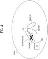
- Fig. 4 illustrates an example in which the beam failure is detected in a primary cell (PCell) functioning as a serving cell.
- Fig. 4 illustrates an example in which the PSCell has a total of three beams #0 to #2.
- the MAC entity of the UE 100 detects the beam failure during communication using a certain beam (for example, the beam #0) in the PSCell.
- the MAC entity of the UE 100 triggers the BFR by initiating a random access procedure for the PCell.
- the MAC entity of the UE 100 starts the BFR timer that defines a duration during which random access is attempted.
- the MAC entity of the UE 100 selects an appropriate beam (for example, the beam #1) to perform the BFR.
- the BFR is completed.
- Fig. 5 illustrates an example in which the beam failure is detected in a secondary cell (SCell) functioning as a serving cell.
- Fig. 5 illustrates an example in which the SCell includes a total of three beams #0 to #2.
- the MAC entity of the UE 100 detects the beam failure during communication using a certain beam (for example, the beam #0) in the SCell.
- the UE 100 triggers the BFR by initiating transmission of a BFR MAC CE.
- the MAC entity of the UE 100 selects a beam (for example, the beam #1) suitable for the SCell, and indicates the selected beam information together with information regarding the beam failure by the BFR MAC CE.
- the MAC entity of the UE 100 receives the PDCCH indicating uplink grant for new transmission of the HARQ process used for the transmission of the BFR MAC CE, the BFR of the SCell 250B is completed.
- LCP logical channel prioritization
- the MAC entity of the UE 100 performs the LCP when generating a MAC protocol data unit (PDU) to be transmitted by using radio resources allocated from the base station 200.
- the MAC entity of the UE 100 determines a data amount of each logical channel to be included in the new MAC PDU in accordance with a priority of each logical channel, so as to satisfy the quality of service (QoS) required for each configured radio bearer (each logical channel), on the basis of on the uplink grant notified by the PDCCH.
- QoS quality of service
- the LCP procedure is applied when new transmission is performed.
- the MAC entity of the UE 100 stores data in the MAC PDU in descending order of priority of from the logical channel until the available size of the MAC PDU is reached.
- the network 10 configures a priority, a prioritized bit rate (PBR), and a bucket size duration (BSD) in the UE 100 for each logical channel in order to control scheduling of uplink data for each logical channel.
- the priority indicates that the higher the value, the lower the priority.
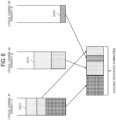
- the MAC entity of the UE 100 manages a variable Bj for each logical channel j.
- Bj is initialized to zero when an associated logical channel is established, and is increased by PBR ⁇ T.
- PBR indicates the prioritized bit rate of the logical channel j
- T indicates a time elapsed since Bj was last increased.
- the value of Bj is not allowed to exceed the bucket size.
- the bucket size is equal to PBR ⁇ BSD. In a case in which the value of Bj is greater than the bucket size of the logical channel j, the MAC entity of UE 100 configures the value of Bj in the bucket size.
- the MAC entity of the UE 100 allocates resources to selected logical channels with Bj > 0 in priority order. It should be noted that, in a case in which the PBR of the logical channel is configured to infinity, the MAC entity allocates resources to all data that can be used for transmission on the logical channel with the PBR configured to infinity before meeting the PBR of the logical channel with the low priority. The MAC entity also decreases Bj by the total size of data (MAC SDU) provided to the logical channel j. In a case in which any resources remain, all selected logical channels are provided with resources in accordance with the priority until either the data of the logical channel or the uplink grant is used up.
- MAC SDU total size of data
- the UE 100 communicates with a master cell group (MCG) 200M managed by a master node (MN) 201M and a secondary cell group (SCG) 200S managed by a secondary node (SN) 201S.
- MCG master cell group
- SCG secondary cell group
- the MN 200M and the SN 200S are connected to each other via a network interface.
- the network interface between the MN 200M and the SN 200 may be an Xn interface or an X2 interface.
- the MN 200M and the SN 200 communicate with each other via the network interface.
- the MN 200M is also referred to as a master base station.
- the SN 200S is also referred to as a secondary base station.
- the MN 200M transmits a predetermined message (for example, an SN addition request message) to the SN 200S, and the MN 200M transmits an RRC reconfiguration message to the UE 100, so that the DC is initiated.
- the UE 100 in the RRC connected state is allocated the radio resources from the schedulers of the MN 200M and the SN 200S, and performs radio communication using the radio resources of the MN 200M and the radio resources of the SN 200S.
- the MN 200M may have a control plane connection with the core network.
- the MN 200M provides main radio resources of the UE 100.
- the MN 200M manages the MCG 201M.
- the MCG 201M is a group of serving cells associated with the MN 200M.
- the MCG 201M includes a primary cell (PCell), and optionally includes one or more secondary cells (SCells).
- the SN 200S may not have a control plane connection with the core network.
- the SN 200S provides additional radio resources to the UE 100.
- the SN 200S manages the SCG 201S.
- the SCG 201S includes a primary secondary cell (PSCell), and optionally includes one or more SCells. Note that the PCell of the MCG 201M and the PSCell of the SCG 201S are also referred to as special cells (SpCells).
- the roles of the nodes communicating with the UE 100 are divided into the MN 200M and the SN 200S. Except for the configuration independently decided in the SN 200S, the MN 200M has the initiative to decide the configuration for the UE 100.
- the two MAC entities 101M and 101S are configured in the UE 100.
- One is a MAC entity 101M for the MCG 201M
- the other is a MAC entity 101S for the SCG 201S.
- the serving cell of the MCG 201M other than the PCell can be activated/deactivated by the MAC control element (CE) received by the MCG 201M.
- the serving cell of the SCG 201S other than the PSCell can be activated/deactivated by the MAC CE received by the SCG 201S.
- the PSCell of the SCG 201S is consistently in the activated state (active state), similarly to the PCell.
- the MN 200M transmits an RRC message for instructing (configuring) the activation or the deactivation of the SCG 201S to the UE 100.
- the RRC message may be an RRC reconfiguration message.
- the UE 100 activates or deactivates the SCG 201S in response to the reception of the instruction.
- the inactive state of the SCG 201S may be a state in which the UE 100 does not transmit at least one of channel status information (CSI), sounding reference signal (SRS), and UL-shared channel (UL-SCH) to each serving cell (particularly, the PSCell) belonging to the SCG 201S in the inactive state, and/or a state in which the UE 100 does not monitor physical downlink control channel (PDCCH).
- CSI channel status information
- SRS sounding reference signal
- UL-SCH UL-shared channel
- PSCell physical downlink control channel
- the network 10 (for example, the MN 200M) can configure the UE 100 to perform the BFD on the SCG 201S (particularly, the PSCell) when the SCG 2015 is in the inactive state.
- the network 10 for example, the MN 200M
- the conventional MAC reset process is executed at the time of RRC reconfiguration or the like, and is a process of resetting the MAC parameters, and for example, the following is executed:
- the UE 100 In a case in which the UE 100 is configured to perform the BFD on the SCG 201S (particularly, the PSCell) when the SCG 201S is in the inactive state, if the UE 100 resets the BFD parameters (particularly, the BFI count value) when the SCG 201S is switched to the inactive state, the detection state in the BFD until that point is initialized. As a result, after the SCG 201S enters the inactive state, the BFD is delayed, and it becomes a state in which a beam with low quality is configured during that time. Therefore, the current SCG 201S deactivation method has room for improvement in efficiently performing the BFD when the SCG 201S is in the inactive state.
- a method of controlling the LCP is not decided.
- the value of the variable Bj in the LCP may increase.
- the SCG 201S is activated, the LCP is performed in a state where the variable Bj is already accumulated. Therefore, the inappropriate LCP is likely to be performed when the SCG 201S is switched from the inactive state to the active state.
- the UE 100 includes a communicator 110 and a controller 120.
- the communicator 110 performs radio communication with the base station 200 by transmitting and receiving a radio signal to and from the base station 200.
- the communicator 110 includes at least one transmitter 111 and at least one receiver 112.
- the transmitter 111 and the receiver 112 may include a plurality of antennas and RF circuits.
- the antenna converts a signal into a radio wave and emits the radio wave into space. Further, the antenna receives a radio wave in space and converts the radio wave into a signal.
- the RF circuit performs analog processing of a signal transmitted and received via the antenna.
- the RF circuit may include a high frequency filter, an amplifier, a modulator, a low pass filter, and the like.
- the controller 120 performs various types of control in the UE 100.
- the controller 120 controls communication with the base station 200 via the communicator 110.
- the operation of the UE 100 described above and described later may be an operation under the control of the controller 120.
- the controller 120 may include at least one processor capable of executing a program and a memory that stores the program.
- the processor may execute the program to perform the operation of the controller 120.
- the controller 120 may include a digital signal processor that executes digital processing of the signal transmitted and received via the antenna and the RF circuit.
- the digital processing includes processing of the protocol stack of the RAN.
- the memory stores a program executed by the processor, parameters related to the program, and data related to the program.
- the memory may include at least one of a read only memory (ROM), an erasable programmable read only memory (EPROM), an electrically erasable programmable read only memory (EEPROM), a random access memory (RAM), and a flash memory. All or a part of the memory may be included in the processor.
- ROM read only memory
- EPROM erasable programmable read only memory
- EEPROM electrically erasable programmable read only memory
- RAM random access memory
- flash memory All or a part of the memory may be included in the processor.
- the UE 100 configured as described above performs DC communication with the MCG 201M and the SCG 201S (see Fig. 7 ).
- the controller 120 includes a MAC entity 101S associated with the SCG 201S.
- the receiver 112 receives an SCG deactivation instruction for causing the SCG 201S to enter the inactive state.
- the receiver 112 may receive an RRC message including the SCG deactivation instruction from the MN 200M (MCG 201M).
- the MAC entity 101S manages the BFD parameters for performing the BFD on the SCG 201S (particularly, the PSCell).
- the controller 120 performs a process of resetting the MAC entity 101S while maintaining the BFD parameters in response to the reception of the SCG deactivation instruction. Accordingly, since the BFD parameters (for example, the BFI count value and the BFD timer) are not reset when the SCG 201S is switched to the inactive state, the detection state in the BFD until that point is continued. As a result, the beam failure can be detected by performing the BFD promptly after the SCG 201S enters the inactive state. That is, even after entering the SCG inactive state, the state before entering is maintained, so the BFD and the BFR can be continuously executed, and the execution delay can be prevented.
- the BFD parameters for example, the BFI count value and the BFD timer
- the controller 120 may perform a process of resetting the MAC entity 101S while resetting or stopping the BFD parameters in response to the reception of the SCG deactivation instruction. As described above, since the BFD parameters are reset or stopped, the processing load of the UE 100 can be reduced.
- the MAC entity 101S associated with the SCG 201S manages, for each logical channel, the variable Bj that is a variable for allocating the uplink resources to each logical channel used for communication with the SCG 201S and has a value increasing with the lapse of time.
- the controller 120 performs a first process when the SCG 201S is switched to the inactive state, performs a second process while the SCG 201S is in the inactive state, and performs a third process when the SCG 201S is switched to the active state.
- the controller 120 performs the first to third processes such that the value of the variable Bj becomes zero when the SCG 201S is switched to the active state.
- the LCP can be prevented from being performed in the state in which the variable Bj has already been accumulated. Therefore, it is possible to perform appropriate LCP when the SCG 201S is switched from the inactive state to the active state.
- At least some of the first to third processes may be different from the other processes.
- the first process may be a process in the partial reset of the MAC entity 101S.
- the third process may be a process in the reset of the MAC entity 101S.
- the base station 200 includes a communicator 210, a network interface 220, and a controller 230.
- the communicator 210 receives a radio signal from the UE 100 and transmits a radio signal to the UE 100.
- the communicator 210 includes at least one transmitter 211 and at least one receiver 212.
- the transmitter 211 and the receiver 212 may include an RF circuit.
- the RF circuit performs analog processing of a signal transmitted and received via the antenna.
- the RF circuit may include a high frequency filter, an amplifier, a modulator, a low pass filter, and the like.
- the network interface 220 transmits and receives a signal to and from a network.
- the network interface 220 receives, for example, a signal from a neighboring base station connected via an Xn interface, which is an interface between base stations, and transmits the signal to the neighboring base station.
- the network interface 220 receives a signal from the core network apparatus 300 connected via the NG interface, for example, and transmits a signal to the core network apparatus 300.
- the controller 230 performs various types of control in the base station 200.
- the controller 230 controls, for example, communication with the UE 100 via the communicator 210.
- the controller 230 controls, for example, communication with a node (for example, the neighboring base station and the core network apparatus 300) via the network interface 220.
- the operation of the base station 200 described above and described later may be an operation under the control of the controller 230.
- the controller 230 may include at least one processor capable of executing a program and a memory that stores the program.
- the processor may execute the program to perform the operation of the controller 230.
- the controller 230 may include a digital signal processor that executes digital processing of a signal transmitted and received via the antenna and the RF circuit.
- the digital processing includes processing of the protocol stack of the RAN.
- the memory stores a program executed by the processor, parameters related to the program, and data related to the program. All or a part of the memory may be included in the processor.
- first to fourth operation examples of the UE 100 related to the BFD and the BFR according to an embodiment will be described with reference to Figs. 10 to 13 .
- the first to fourth operation examples may be implemented such that each operation example is separately and independently performed. Furthermore, the first to fourth operation examples may be implemented such that two or more operation examples are combined.
- the BFD parameters managed by the MAC entity 101S for the SCG 201S include the count value (the BFI counter) obtained by counting the beam failure instance indicators notified from the physical layer of the UE 100 to the MAC entity 101S.
- the MAC entity 101S detects the beam failure in response to the count value of the BFI counter reaching the threshold value.
- the controller 120 of the UE 100 performs the process of resetting the MAC entity 101S without resetting the count value of the BFI counter in response to the reception of the SCG deactivation instruction. Accordingly, since the count value of the BFI counter before the SCG 201S is deactivated is maintained, the beam failure can be detected promptly after the SCG 201S is deactivated.
- the controller 120 of the UE 100 performs the process of resetting the MAC entity 101S while resetting the count value of the BFI counter in response to the reception of the SCG deactivation instruction.
- the count value of the BFI counter is reset, the memory use amount and the processing load of the UE 100 can be reduced, and the occurrence of an unexpected error can be prevented.
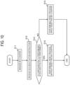
- Fig. 10 is a flowchart illustrating the present operation example.
- step S11 the controller 120 of the UE 100 (specifically, the MAC entity 101S for the SCG 201S) manages the BFI counter for each serving cell included in the SCG 201S.
- step S12 the receiver 112 of the UE 100 receives the SCG deactivation instruction from, for example, the MN 200M (MCG 201M).
- MN 200M MCG 201M
- step S13 the controller 120 of the UE 100 determines whether it is configured to perform the BFD in the SCG inactive state. For example, in a case in which the receiver 112 receives the RRC message including configuration information for configuring the BFD to be performed in the SCG inactive state from, for example, the MN 200M (MCG 201M), the controller 120 of the UE 100 may determine that it is configured to perform the BFD in the SCG inactive state.
- MN 200M MN 200M
- step S14 the controller 120 of the UE 100 performs the process of resetting the MAC entity 101S without resetting the count value of the BFI counter in response to the reception of the SCG deactivation instruction.
- step S15 the controller 120 of the UE 100 performs the process of resetting the MAC entity 101S while resetting the count value of the BFI counter in response to the reception of the SCG deactivation instruction.
- the BFD parameters managed by the MAC entity 101S for the SCG 201S include the BFD timer for the BFD.
- the MAC entity 101S detects the beam failure in response to the count value of the BFI counter reaching the threshold value before the BFD timer expires.
- the controller 120 of the UE 100 performs the process of resetting the MAC entity 101S without stopping the BFD timer in response to the reception of the SCG deactivation instruction. As described above, as the BFD timer is not stopped, the BFD can be appropriately performed even when the SCG 201S is deactivated.
- the controller 120 of the UE 100 performs the process of resetting the MAC entity 101S while stopping the BFD timer in response to the reception of the SCG deactivation instruction. As the BFD timer is stopped, the processing load of the UE 100 can be reduced, and the occurrence of an unexpected error can be prevented.
- Fig. 11 is a flowchart illustrating the present operation example. Here, the description will proceed focusing on the differences from the first operation example regarding the BFD and the BFR, and redundant description will be omitted.
- step S21 the controller 120 of the UE 100 (specifically, the MAC entity 101S for the SCG 201S) manages the BFD timer for each serving cell included in the SCG 201S.
- step S22 the receiver 112 of the UE 100 receives the SCG deactivation instruction from, for example, the MN 200M (MCG 201M).
- step S23 the controller 120 of the UE 100 determines whether it is configured to perform the BFD in the SCG inactive state.
- step S24 the controller 120 of the UE 100 performs the process of resetting the MAC entity 101S without stopping the BFD timer in response to the reception of the SCG deactivation instruction.
- step S25 the controller 120 of the UE 100 performs the process of resetting the MAC entity 101S while stopping the BFD timer in response to the reception of the SCG deactivation instruction.
- the MAC entity 101S for the SCG 201S manages the BFR timer for performing the BFR when the beam failure is detected by the BFD.
- the controller 120 of the UE 100 performs the process of resetting the MAC entity 101S without stopping the BFR timer in response to the reception of the SCG deactivation instruction. As the BFR timer is not stopped, the BFR can be appropriately performed even when the SCG 201S is deactivated.
- the controller 120 of the UE 100 performs the process of resetting the MAC entity 101S while stopping the BFR timer in response to the reception of the SCG deactivation instruction. As the BFR timer is stopped, the processing load of the UE 100 can be reduced, and the occurrence of an unexpected error can be prevented.
- Fig. 12 is a flowchart illustrating the present operation example. Here, the description will proceed focusing on the differences from the first operation example regarding the BFD and the BFR, and redundant description will be omitted.
- step S31 the controller 120 of the UE 100 (specifically, the MAC entity 101S for the SCG 201S) manages the BFR timer for each serving cell included in the SCG 201S.
- step S32 the receiver 112 of the UE 100 receives the SCG deactivation instruction from, for example, the MN 200M (MCG 201M).
- step S33 the controller 120 of the UE 100 determines whether it is configured to perform the BFD in the SCG inactive state.
- step S34 the controller 120 of the UE 100 performs the process of resetting the MAC entity 101S without stopping the BFR timer in response to the reception of the SCG deactivation instruction.
- step S35 the controller 120 of the UE 100 performs the process of resetting the MAC entity 101S while stopping the BFR timer in response to the reception of the SCG deactivation instruction.
- the MAC entity 101S for the SCG 201S triggers the BFR in response to the detection of the beam failure by the BFD.
- the controller 120 of the UE 100 performs the process of resetting the MAC entity 101S without canceling the triggered BFR. As the triggered BFR is not canceled, the BFR can be appropriately performed even when the SCG 201S is deactivated.
- the controller 120 of the UE 100 performs the process of resetting the MAC entity 101S while canceling the triggered BFR. As the triggered BFR is canceled, the processing load of the UE 100 can be reduced, and the occurrence of an unexpected error can be prevented.
- Fig. 13 is a flowchart illustrating the present operation example. Here, the description will proceed focusing on the differences from the first operation example regarding the BFD and the BFR, and redundant description will be omitted.
- step S41 the controller 120 of the UE 100 (specifically, the MAC entity 101S for the SCG 201S) triggers the BFR for the SCG 201S.
- step S42 the receiver 112 of the UE 100 receives the SCG deactivation instruction from, for example, the MN 200M (MCG 201M).
- step S43 the controller 120 of the UE 100 determines whether it is configured to perform the BFD in the SCG inactive state.
- step S44 the controller 120 of the UE 100 performs the process of resetting the MAC entity 101S without canceling the triggered BFR in response to the reception of the SCG deactivation instruction.
- step S45 the controller 120 of the UE 100 performs the process of resetting the MAC entity 101S while canceling the triggered BFR in response to the reception of the SCG deactivation instruction.
- first to fourth operation examples of the UE 100 related to the LCP according to an embodiment will be described with reference to Figs. 14 to 17 .
- the UE 100 performs any operation of the first to fourth operation examples.
- the controller 120 of the UE 100 manages the variable Bj for each logical channel.
- the controller 120 of the UE 100 performs a first process when the SCG 201S is switched to the inactive state, performs a second process while the SCG 201S is in the inactive state, and performs a third process when the SCG 201S is switched to the active state.
- the controller 120 of the UE 100 performs the first to third processes such that the value of the variable Bj becomes zero when the SCG 201S is switched to the active state.
- a first process is a processing of setting the value of the variable Bj to zero (that is, performing initialization)
- a second process is a process of maintaining the value of the variable Bj
- a third processing is a process of maintaining the value of the variable Bj.
- Fig. 14 is a flowchart illustrating the present operation example.
- step S51 the controller 120 of the UE 100 (MAC entity 101S for SCG 201S) sets the variable Bj managed by the MAC entity 101S to zero in the partial MAC reset at the time of SCG deactivation.
- step S52 the controller 120 of the UE 100 (MAC entity 101S for SCG 201S) maintains the variable Bj managed by the MAC entity 101S without increasing the variable Bj while the SCG is in the inactive state.
- step S53 the controller 120 of the UE 100 (MAC entity 101S for SCG 201S) maintains the variable Bj managed by the MAC entity 101S without increasing the variable Bj in the MAC reset at the time of SCG activation (that is, the variable Bj is maintained at zero).
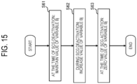
- a first process is a processing of maintaining the value of the variable Bj
- a second process is a process of increasing the value of the variable Bj
- a third processing is a process of setting the value of the variable Bj to zero (that is, performing initialization).
- Fig. 15 is a flowchart illustrating the present operation example.
- step S61 the controller 120 of the UE 100 (MAC entity 101S for SCG 201S) maintains the variable Bj managed by the MAC entity 101S without performing initialization in the partial MAC reset at the time of SCG deactivation.
- step S62 the controller 120 of the UE 100 (MAC entity 101S for SCG 201S) increases the variable Bj managed by the MAC entity 101S by PBR ⁇ T while the SCG is in the inactive state.
- step S63 the controller 120 of the UE 100 (MAC entity 101S for SCG 201S) sets the variable Bj managed by the MAC entity 101S to zero (that is, performs initialization) in the MAC reset at the time of SCG activation.
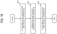
- a first process is a processing of setting the value of the variable Bj to zero
- a second process is a process of increasing the value of the variable Bj
- a third processing is a process of setting the value of the variable Bj to zero.
- Fig. 16 is a flowchart illustrating the present operation example.
- step S71 the controller 120 of the UE 100 (MAC entity 101S for SCG 201S) sets the variable Bj managed by the MAC entity 101S to zero (that is, performs initialization) in the partial MAC reset at the time of SCG deactivation.
- step S72 the controller 120 of the UE 100 (MAC entity 101S for SCG 201S) increases the variable Bj managed by the MAC entity 101S by PBR ⁇ T while the SCG is in the inactive state.
- step S73 the controller 120 of the UE 100 (MAC entity 101S for SCG 201S) sets the variable Bj managed by the MAC entity 101S to zero (that is, performs initialization) in the MAC reset at the time of SCG activation.
- a first process is a processing of maintaining the value of the variable Bj
- a second process is a process of maintaining the value of the variable Bj
- a third processing is a process of setting the value of the variable Bj to zero.
- Fig. 17 is a flowchart illustrating the present operation example.
- step S81 the controller 120 of the UE 100 (MAC entity 101S for SCG 201S) maintains the variable Bj managed by the MAC entity 101S without performing initialization in the partial MAC reset at the time of SCG deactivation.
- step S82 the controller 120 of the UE 100 (MAC entity 101S for SCG 201S) maintains the variable Bj managed by the MAC entity 101S without increasing the variable Bj while the SCG is in the inactive state.
- step S83 the controller 120 of the UE 100 (MAC entity 101S for SCG 201S) sets the variable Bj managed by the MAC entity 101S to zero (that is, performs initialization) in the MAC reset at the time of SCG activation.
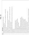
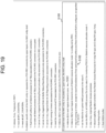
- Figs. 18 to 20 illustrate specification modification examples of the MAC reset.
- the MAC entity 101S of the UE 100 performs the partial MAC reset in a case in which the partial reset of the MAC entity 101S is requested from an upper layer.
- the RRC layer of the UE 100 instructs the MAC entity 101S to perform the partial MAC reset in response to the reception of the SCG deactivation instruction from the network 10.
- the RRC layer of the UE 100 may give, to the MAC entity 101S, a notification indicating that the SCG deactivation instruction has been received from the network 10, and the MAC entity 101S may initiate the partial MAC reset in response to the notification.
- the MAC entity 101S of the UE 100 may receive the SCG deactivation instruction from the SN 200S (SCG 2015) through the MAC CE, and the MAC entity 101S may initiate the partial MAC reset in response to the reception of the SCG deactivation instruction.
- Step S100 may include step S101 of initializing the variable Bj managed by the MAC entity 101S for each logical channel.
- the MAC entity 101S executes the process of step S101 in the case of the partial MAC reset of the first operation example and the third operation example related to the LCP described above, but does not execute the process of step S 101 in the case of the second operation example and the fourth operation example related to the LCP described above.
- Step S100 may include step S101 of initializing the variable Bj managed by the MAC entity 101S for each logical channel.
- the MAC entity 101S executes the process of step S 101 in the case of the partial MAC reset of the first operation example and the third operation example related to the LCP described above, but does not execute the process of step S 101 in the case of the second operation example and the fourth operation example related to the LCP described above.
- Step S 100 may include step S102 of stopping all the timers (the timers being operation) except for the BFD timer (beamFailureDetectionTimer) and the BFR timer (beamFailureRecoveryTimer) when "bfd-and-RLM" which is a parameter of RRC is configured. That is, in a case in which "bfd-and-RLM" is configured, the MAC entity 101S continues the timer operation without stopping the BFD timer (beamFailureDetectionTimer) and the BFR timer (beamFailureRecoveryTimer) at the time of SCG deactivation.
- step S102 of stopping all the timers (the timers being operation) except for the BFD timer (beamFailureDetectionTimer) and the BFR timer (beamFailureRecoveryTimer) when "bfd-and-RLM" which is a parameter of RRC is configured. That is, in a case
- the MAC entity 101S stops the BFD timer (beamFailureDetectionTimer) and the BFR timer (beamFailureRecoveryTimer) at the time of SCG deactivation.
- BFD timer beamFailureDetectionTimer
- BFR timer beamFailureRecoveryTimer
- Step S100 may include step S103 of canceling the triggered BFR when "bfd-and-RLM" which is the parameter of RRC is not configured. That is, in a case in which "bfd-and-RLM" is configured, the MAC entity 101S continues the BFR without canceling the triggered BFR at the time of SCG deactivation. On the other hand, in a case in which "bfd-and-RLM" is not configured, the MAC entity 101S cancels the triggered BFR at the time of SCG deactivation.
- Step S100 may include step S104 of resetting the BFI counter in a case in which "bfd-and-RLM" which is a parameter of RRC is not configured. That is, in a case in which "bfd-and-RLM" is configured, the MAC entity 101S continues the counting operation without resetting all the BFI counters managed by the MAC entity 101S at the time of SCG deactivation. On the other hand, in a case in which "bfd-and-RLM" is not configured, the MAC entity 101S resets all the BFI counters managed by the MAC entity 101S at the time of SCG deactivation.
- Figs. 21 to 23 illustrate specification modification examples of the beam failure detection and recovery procedure (BFD and BFR).
- the BFD and the BFR may include step S200 related to SCG deactivation/activation.
- Step S200 may include step S201 of setting the BFI counter to zero for the serving cell belonging to the SCG in the inactive state while the SCG is in the inactive state. Note that, in a case in which the counting operation is continued without resetting the BFI counter at the time of SCG deactivation, the BFI counter may be set to zero after the counting operation ends.
- Step S200 may include step S202 of considering that the beam failure recovery procedure (BFR) has been successfully completed for the serving cell belonging to the SCG in the inactive state while the SCG is in the inactive state.
- BFR beam failure recovery procedure
- Fig. 24 illustrates a specification modification example of the logical channel prioritization (LCP).
- the LCP may include step S300 related to SCG deactivation/activation.
- Step S300 is a process of increasing the variable Bj managed by the MAC entity 101S in a case in which the SCG is in the active state.
- the variable Bj managed by the MAC entity 101S is not increased but maintained. This operation corresponds to the first operation example and the fourth operation example related to the LCP described above.
- any one of the four configurations illustrated in Fig. 10 may be applied as the configuration of the DC.
- a configuration in which the MN 200M is an E-UTRA base station and the SN 200S is an NR base station is referred to as (NG) EN-DC.
- the CN 30 is an EPC
- a configuration in which the MN 200M is an E-UTRA base station (eNB) and the SN 200S is an NR base station (en-gNB) is referred to as EN-DC.
- a configuration in which the MN 200M is an E-UTRA base station (ng-eNB) and the SN 200S is an NR base station (gNB) is referred to as NGEN-DC.
- a configuration in which the MN 200M is an NR base station (gNB) and the SN 200S is an E-UTRA base station (ng-eNB) is referred to as NE-DC.
- a configuration in which the MN 200M is an NR base station (gNB) and the SN 200S is also an NR base station (gNB) is referred to as NR-DC.
- the DC in which the UE 100 communicates with the two base stations has been described, but the UE 100 may perform multiple connection with three or more base stations. Further, the UE 100 may perform multiple connection with two or more other communication apparatuses not limited to the base station.
- the operation sequence (and the operation flow) in the above-described embodiment may not necessarily be executed in time series according to the order described in the flow diagram or the sequence diagram.
- the steps in the operation may be performed in an order different from the order described in the flowchart or the sequence diagram, or may be performed in parallel.
- some of the steps in the operation may be removed or additional steps may be added to the process.
- the operation sequence (and the operation flow) in the above-described embodiment may be separately and independently performed.
- the operation sequence (and the operation flow) in the above-described embodiment may be implemented by combining two or more operation sequences (and operation flows). For example, some steps of one operation flow may be added to other operation flows, or some steps of one operation flow may be replaced with some steps of other operation flows.
- the mobile communication system based on the NR is described as the example of the mobile communication system 1.
- the mobile communication system 1 is not limited to this example.
- the mobile communication system 1 may be a system conforming to the technical specification of any of LTE or other generation systems (for example, sixth generation) of the 3GPP standard.
- the base station 200 may be an eNB configured to provide protocol terminations of E-UTRA user plane and control plane toward the UE 100 in LTE.
- the mobile communication system 1 may be a system conforming to a TS defined in a standard other than the 3GPP standard.
- the base station 200 may be an integrated access and backhaul (IAB) donor or an IAB node.
- the UE 100 may be an MT in an IAB node.
- a program for causing a computer to execute each process performed by the UE 100 or the base station 200 may be provided.
- the program may be recorded in a computer readable medium.
- the program may be installed in the computer by using the computer readable medium.
- the computer readable medium on which the program is recorded may be a non-transitory recording medium.
- the non-transitory recording medium is not particularly limited, but may be, for example, a recording medium such as a CD-ROM or a DVD-ROM.
- a circuit that executes each processing performed by the UE 100 or the base station 200 may be integrated, and at least a part of the UE 100 or the base station 200 may be a semiconductor integrated circuit (chipset, SoC (system-on-a-chip)).
- transmit may mean to perform processing of at least one layer in a protocol stack used for transmission, or may mean to physically transmit a signal wirelessly or by wire.
- transmit may mean a combination of performing the processing of at least one layer and physically transmitting a signal wirelessly or by wire.
- receiver may mean to perform processing of at least one layer in a protocol stack used for reception, or may mean to physically receive a signal wirelessly or by wire.
- receiver may mean a combination of performing the processing of at least one layer and physically receiving a signal wirelessly or by wire.
- acquire may mean to acquire information from stored information, may mean to acquire information from information received from another node, or may mean to acquire the information by generating information.
- acquire may mean to acquire information from stored information, may mean to acquire information from information received from another node, or may mean to acquire the information by generating information.
- “include (include)” and “comprise (comprise)” do not mean to include only the listed items, but mean that the terms may include only the listed items or may include additional items in addition to the listed items.
- “or (or)” does not mean exclusive OR but means OR.
- a communication apparatus (100) configured to perform communication with a master cell group (MCG) (201M) managed by a master node (200M) and a secondary cell group (SCG) (2015) managed by a secondary node (200S), the communication apparatus including:
- the communication apparatus (100) according to supplementary note 1, wherein at least some of the first to third processes are different from the other processes.
- the communication apparatus (100) according to supplementary note 1 or 2,
- the communication apparatus (100) according to any one of supplementary notes 1 to 3,
- the communication apparatus (100) according to any one of supplementary notes 1 to 3,
- the communication apparatus (100) according to any one of supplementary notes 1 to 3,
- the communication apparatus (100) according to any one of supplementary notes 1 to 3,
- the communication apparatus (100) according to any one of supplementary notes 1 to 7, wherein the inactive state is a state in which, for each serving cell belonging to the SCG in the inactive state, the communication apparatus (100) does not transmit at least one of channel status information (CSI), a random access channel (RACH), a sounding reference signal (SRS), and a UL-shared channel (UL-SCH) and/or a state in which the communication apparatus (100) does not monitor a physical downlink control channel (PDCCH).
- CSI channel status information
- RACH random access channel
- SRS sounding reference signal
- UL-SCH UL-shared channel
Landscapes
- Engineering & Computer Science (AREA)
- Signal Processing (AREA)
- Computer Networks & Wireless Communication (AREA)
- Mobile Radio Communication Systems (AREA)
Abstract
Description
- The present application claims priority to
Japanese Patent Application No. 2022-001326 (filed on January 6, 2022 - The present disclosure relates to a communication apparatus and a communication method used in a mobile communication system.
- In a mobile communication system conforming to a technical specification of a 3rd Generation Partnership Project (hereinafter, 3GPP (registered trademark)) which is a mobile communication system standardization project, dual connectivity (DC) has been introduced. In the DC, a communication apparatus (user equipment (UE)) performs communication with a master cell group (MCG) managed by a master node (also referred to as a "master base station") and a secondary cell group (SCG) managed by a secondary node (also referred to as a "secondary base station").
- In the 3GPP, a technique of temporarily deactivating an SCG configured in a communication apparatus in order to suppress power consumption of the communication apparatus in the DC has been reviewed. For example, the master node instructs the communication apparatus to activate or deactivate the SCG. When the SCG is in the inactive state, communication between the communication apparatus and the SCG is stopped, so power consumption of the communication apparatus is suppressed.
- On the other hand, the 3GPP technical specification specifies logical channel prioritization (LCP) (see
Non Patent Literatures 1 to 3). Specifically, a medium access control (MAC) entity of the communication apparatus manages, for each logical channel, a variable that is for uplink resource allocation to each logical channel and has a value increasing with the lapse of time. In the 3GPP technical specification, the variable of each logical channel "j" is referred to as "Bj". Each time uplink transmission is performed, the communication apparatus performs uplink resource allocation to each logical channel by using the variable Bj being managed. -
- Non Patent Literature 1: 3GPP technical specification: TS 38.321 V16.7.0
- Non Patent Literature 2: 3GPP Contribution: R2-2111638
- Non Patent Literature 3: 3GPP Contribution: R2-2111314
- The communication apparatus switches the SCG to the inactive state in response to reception of an instruction for switching the SCG to the inactive state, and switches the SCG to the active state in response to reception of an instruction for switching the SCGto the active state. A method for controlling the LCP in this operation is not yet decided.
- Here, according to the current 3GPP technical specification, even in a case in which the SCG is in the inactive state and the communication apparatus has no data to be transmitted to the SCG, the value of the variable Bj in the LCP may increase. Thereafter, when the SCG is activated, the LCP is performed in a state in which the variable Bj is already accumulated. Therefore, the inappropriate LCP is likely to be performed when the SCG is switched from the inactive state to the active state.
- In light of the foregoing circumstances, the present disclosure provides a communication apparatus and a communication method which are capable of performing appropriate LCP when the SCG is switched from the inactive state to the active state.
- A communication apparatus according to a first feature is configured to perform communication with a master cell group (MCG) managed by a master node and a secondary cell group (SCG) managed by a secondary node. The communication apparatus comprises a controller including a medium access control (MAC) entity associated with the SCG. The MAC entity manages, for each logical channel, a variable that is for uplink resource allocation to each logical channel used for communication with the SCG and has a value increasing with lapse of time, and the controller is configured to perform, for the variable, a first process in reset of the MAC entity by deactivation of the SCG, perform a second process while the SCG is in an inactive state, and perform a third process when the SCG is activated.
- A communication method according to a second feature performs communication with a master cell group (MCG) managed by a master node and a secondary cell group (SCG) managed by a secondary node. The communication method comprises the steps of: managing, by a medium access control (MAC) entity associated with the SCG, for each logical channel, a variable that is for uplink resource allocation to each logical channel used for communication with the SCG and has a value increasing with lapse of time; and performing, for the variable, a first process in reset of the MAC entity by deactivation of the SCG, performing a second process while the SCG is in an inactive state, and performing a third process when the SCG is activated.
- The foregoing and other objects, features, and advantages of the present disclosure will become more apparent from the following detailed description with reference to the accompanying drawings. The drawings are as follows.
-
Fig. 1 is a diagram illustrating a configuration of a mobile communication system according to an embodiment. -
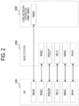
Fig. 2 is a diagram illustrating a configuration example of a protocol stack in a mobile communication system according to an embodiment. -
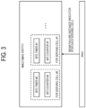
Fig. 3 is a diagram for describing an overview of BFD and BFR according to an embodiment, and is a diagram illustrating an internal process of a UE. -
Fig. 4 is a diagram for describing an overview of BFD and BFR according to an embodiment, and is a diagram illustrating an example in which a beam failure is detected in a PCell. -
Fig. 5 is a diagram for describing an overview of BFD and BFR according to an embodiment, and is a diagram illustrating an example in which a beam failure is detected in an SCell. -
Fig. 6 is a diagram for describing an overview of LCP according to an embodiment. -
Fig. 7 is a diagram for describing an overview of DC according to an embodiment. -
Fig. 8 is a diagram illustrating a configuration of a UE according to an embodiment. -
Fig. 9 is a diagram illustrating a configuration of a base station according to an embodiment. -
Fig. 10 is a diagram illustrating a first operation example related to BFD and BFR according to an embodiment. -
Fig. 11 is a diagram illustrating a second operation example related to BFD and BFR according to an embodiment. -
Fig. 12 is a diagram illustrating a third operation example related to BFD and BFR according to an embodiment. -
Fig. 13 is a diagram illustrating a fourth operation example related to BFD and BFR according to an embodiment. -
Fig. 14 is a diagram illustrating a first operation example related to LCP according to an embodiment. -
Fig. 15 is a diagram illustrating a second operation example related to LCP according to an embodiment. -
Fig. 16 is a diagram illustrating a third operation example related to LCP according to an embodiment. -
Fig. 17 is a diagram illustrating a fourth operation example related to LCP according to an embodiment. -
Fig. 18 is a diagram illustrating a specification modification example of MAC reset according to an embodiment. -
Fig. 19 is a diagram illustrating a specification modification example of MAC reset according to an embodiment. -
Fig. 20 is a diagram illustrating a specification modification example of MAC reset according to an embodiment. -
Fig. 21 is a diagram illustrating a specification modification example of beam failure detection and recovery procedure (BFD and BFR) according to an embodiment. -
Fig. 22 is a diagram illustrating a specification modification example of beam failure detection and recovery procedure (BFD and BFR) according to an embodiment. -
Fig. 23 is a diagram illustrating a specification modification example of beam failure detection and recovery procedure (BFD and BFR) according to an embodiment. -
Fig. 24 is a diagram illustrating a specification modification example of logical channel prioritization (LCP) according to an embodiment. -
Fig. 25 is a diagram illustrating a variation of DC according to an embodiment. - Amobile communication system according to an embodiment will be described with reference to the drawings. In the description of the drawings, the same or similar parts are denoted by the same or similar reference numerals.
- First, a configuration of a
mobile communication system 1 according to an embodiment will be described with reference toFig. 1 . - The
mobile communication system 1 is, for example, a system conforming to a technical specification (TS) of 3GPP. Hereinafter, a mobile communication system based on NR radio access (NR) which is a radio access technology (RAT) of a fifth generation (5G) system of 3GPP will be mainly described as themobile communication system 1. Here, themobile communication system 1 may have a configuration based on at least partially on evolved universal terrestrial radio access (E-UTRA)/long term evolution (LTE) which is a RAT of a fourth generation (4G) system of 3GPP. - The
mobile communication system 1 includes anetwork 10 and a communication apparatus (user equipment (UE)) 100 that communicates with thenetwork 10. Thenetwork 10 includes a radio access network (RAN) 20 and a core network (CN) 30. TheRAN 20 is a next generation radio access network (NG-RAN) in 5G/NR. TheRAN 20 may be an evolved universal terrestrial radio access network (E-UTRAN) in 4G/LTE. TheCN 30 is a 5th generation core network (5GC) in 5G/NR. TheCN 30 may be an evolved packet core (EPC) in 4G/LTE. - The
UE 100 is an equipment used by a user. TheUE 100 is, for example, a mobile apparatus such as a mobile phone terminal such as a smartphone, a tablet terminal, a notebook personal computer (PC), a communication module, or a communication card. TheUE 100 may be a vehicle (for example, a car or a train) or an apparatus provided in the vehicle. TheUE 100 may be a transport body other than a vehicle (for example, a ship or an airplane) or an apparatus provided in the transport body. TheUE 100 may be a sensor or an apparatus provided in the sensor. It is noted that theUE 100 may be referred to as other names such as a mobile station, a mobile terminal, a mobile apparatus, a mobile unit, a subscriber station, a subscriber terminal, a subscriber apparatus, a subscriber unit, a wireless station, a wireless terminal, a wireless apparatus, a wireless unit, a remote station, a remote terminal, a remote apparatus, or a remote unit. - The
RAN 20 includes a plurality ofbase stations 200. Each of thebase stations 200 manages at least one cell. A cell forms a minimum unit of a communication area. For example, one cell belongs to one frequency (a carrier frequency) and is formed by one component carrier. The term "cell" may represent a radio communication resource, and may also represent a communication target of theUE 100. Eachbase station 200 can perform radio communication with theUE 100 existing in its own cell. Thebase station 200 communicates with theUE 100 by using a protocol stack of the RAN. Thebase station 200 provides user plane and control plane protocol terminations towards theUE 100 and is connected to theCN 30 via a network interface between the base station and the CN. Thebase station 200 in 5G/NR is referred to as a gNodeB (gNB), and thebase station 200 in 4G/LTE is referred to as an eNodeB (eNB). Further, the interface between the base station and the CN in 5G/NR is referred to as an NG interface, and the interface between the base station and the CN in 4G/LTE is referred to as an S1 interface. Thebase station 200 is connected to a neighboring base station via a network interface between base stations. An interface between base stations in 5G/NR is referred to as an Xn interface, and an interface between base stations in 4G/LTE is referred to as an X2 interface. - The
CN 30 includes acore network apparatus 300. Thecore network apparatus 300 is an access and mobility management function (AMF) and/or a user plane function (UPF) in 5G/NR. Thecore network apparatus 300 may be a mobility management entity (MME) and/or a serving gateway (S-GW) in 4G/LTE. The AMF/MME performs mobility management of theUE 100. The UPF/S-GW provides a function specialized for user plane processing. - Next, a configuration example of a protocol stack in the
mobile communication system 1 according to the embodiment will be described with reference toFig. 2 . - A protocol of a radio section between the
UE 100 and thebase station 200 includes a physical (PHY) layer, a medium access control (MAC) layer, a radio link control (RLC) layer, a packet data convergence protocol (PDCP) layer, and a radio resource control (RRC) layer. - The PHY layer performs coding/decoding, modulation/demodulation, antenna mapping/demapping, and resource mapping/demapping. Data and control information are transmitted between the PHY layer of the
UE 100 and the PHY layer of thebase station 200 via a physical channel. - The physical channel includes a plurality of OFDM symbols in the time domain and a plurality of subcarriers in the frequency domain. One subframe includes a plurality of OFDM symbols in the time domain. A resource block is a resource allocation unit, and includes a plurality of OFDM symbols and a plurality of subcarriers. A frame can be composed of 10 ms, and can include 10 subframes composed of 1 ms. A number of slots corresponding to a subcarrier spacing may be included in the subframe.
- Among the physical channels, a physical downlink control channel (PDCCH) plays a central role for purposes such as, for example, downlink scheduling allocation, uplink scheduling grant, and transmission power control. For example, the
UE 100 performs blind decoding of the PDCCH using a cell-radio network temporary identifier (C-RNTI) and a modulation and coding scheme-C-RNTI (MCS-C-RNTI) or a configured scheduling-RNTI (CS-RNTI) allocated from thebase station 200 to theUE 100, and acquires a DCI which has been successfully decoded as a DCI addressed to its own UE. Here, a cyclic redundancy check (CRC) parity bit scrambled by the C-RNTI and the MCS-C-RNTI or the CS-RNTI is added to the DCI transmitted from thebase station 200. - In the NR, the
UE 100 can use a bandwidth narrower than a system bandwidth (that is, the bandwidth of the cell). Thebase station 200 configures a bandwidth part (BWP) including consecutive PRBs in theUE 100. TheUE 100 transmits and receives data and a control signal in an active BWP. In theUE 100, for example, a maximum of four BWPs can be configured. The BWPs may have different subcarrier spacings. Further, the frequencies of the BWPs may overlap with each other. In a case in which a plurality of BWPs are configured for theUE 100, thebase station 200 can designate which BWP is to be activated by control in downlink. As a result, thebase station 200 can dynamically adjust a UE bandwidth according to the amount of data traffic of theUE 100 and the like, and can reduce the UE power consumption. - The
base station 200 can configure, for example, a maximum of three control resource sets (CORESETs) in each of a maximum of four BWPs on a serving cell. The CORESET is a radio resource for control information to be received by theUE 100. A maximum of 12 CORESETs can be configured on the serving cell in theUE 100. Each CORESET hasindices 0 to 11. For example, the CORESET includes 6 resource blocks (PRB) and one, two, or 3 consecutive OFDM symbols in the time domain. - The MAC layer performs priority control of data, a retransmission process by hybrid ARQ (HARQ: Hybrid Automatic Repeat reQuest), a random access procedure, and the like. Data and control information are transmitted between the MAC layer of the
UE 100 and the MAC layer of thebase station 200 via a transport channel. The MAC layer of thebase station 200 includes a scheduler. The scheduler determines uplink and downlink transport formats (transport block size, and modulation and coding scheme (MCS)) and allocated resources to theUE 100. - The RLC layer transmits data to the RLC layer on the reception side using the functions of the MAC layer and the PHY layer. Data and control information are transmitted, via a logical channel, between the RLC layer of the
UE 100 and the RLC layer of thebase station 200. - The PDCP layer performs header compression/decompression and encryption/decryption.
- A service data adaptation protocol (SDAP) layer may be provided as an upper layer of the PDCP layer. The SDAP layer performs mapping between an IP flow that is a unit in which a core network performs quality of service (QoS) control, and a radio bearer that is a unit in which an access stratum (AS) performs QoS control.
- The RRC layer controls a logical channel, a transport channel, and a physical channel according to establishment, reestablishment, and release of the radio bearer. RRC signaling for various configurations is transmitted between the RRC layer of the
UE 100 and the RRC layer of thebase station 200. In a case in which there is an RRC connection between the RRC of theUE 100 and the RRC of thebase station 200, theUE 100 is in an RRC connected state. In a case in which there is no RRC connection between the RRC of theUE 100 and the RRC of thebase station 200, theUE 100 is in an RRC idle state. In a case in which an RRC connection between the RRC of theUE 100 and the RRC of thebase station 200 is suspended, theUE 100 is in an RRC inactive state. - A non-access stratum (NAS) layer located above the RRC layer performs session management and mobility management of the
UE 100. NAS signaling is transmitted between the NAS layer of theUE 100 and the NAS layer of the core network apparatus 300 (AMF/MME). Note that theUE 100 has an application layer and the like in addition to the radio interface protocol. - Next, an overview of beam failure detection (BFD) and beam failure recovery (BFR) according to an embodiment will be described with reference to
Figs. 3 to 5 . - The 5G/NR can perform broadband transmission in a high frequency band such as a millimeter wave band or a terahertz wave band as compared with 4G/LTE. In order to compensate for radio wave attenuation for radio waves in such a high frequency band, the 5G/NR uses highly directional beamforming using a large number of antennas between the
base station 200 and theUE 100 to obtain high beam gain. In the NR, a beam control technology for establishing and maintaining a beam pair between thebase station 200 and theUE 100 is introduced. The BFD and the BFR are one of such beam control techniques. - For the BFD, the
base station 200 configures, in theUE 100, a downlink reference signal resource for detecting beam failure. The reference signal resource is any one of an SS/PBCH block (SSB) and a channel state information reference signal (CSI-RS). The SSB includes a primary synchronization signal (PSS), a secondary synchronization signal (SSS), a physical broadcast channel (PBCH), and a demodulation reference signal (DMRS). For example, the SSB may be composed of four consecutive OFDM symbols in the time domain. In addition, the SSB may be composed of 240 consecutive subcarriers (that is, 20 resource blocks) in the frequency domain. The PBCH is a physical channel that carries a master information block (MIB). The CSI-RS is a reference signal that is transmitted for theUE 100 to measure a state of a radio channel. - As illustrated in
Fig. 3 , in theUE 100, the MAC layer (MAC entity) manages a beam failure instance (BFI) counter and a BFD timer for each serving. The parameters (for example, the BFI counter and/or the BFD timer) managed by the MAC entity to perform the BFD are referred to as BFD parameters. The MAC entity of theUE 100 counts a beam failure event (beam failure instance indicator) notified from the PHY layer for a certain serving cell by the BFI counter, and detects (recognizes) the beam failure for the serving cell when a count value of the BFI counter becomes equal to or larger than a threshold value before the BFD timer expires. The BFD timer is a timer that starts or restarts when the MAC entity receives the beam failure instance indicator. The threshold value of the BFI counter and the timer configuration value of the BFD timer are configured in theUE 100 from thenetwork 10. When the beam failure is detected, the MAC entity of theUE 100 performs the BFR to recover from the beam failure. -
Fig. 4 illustrates an example in which the beam failure is detected in a primary cell (PCell) functioning as a serving cell.Fig. 4 illustrates an example in which the PSCell has a total of threebeams # 0 to #2. The MAC entity of theUE 100 detects the beam failure during communication using a certain beam (for example, the beam #0) in the PSCell. In this case, the MAC entity of theUE 100 triggers the BFR by initiating a random access procedure for the PCell. Here, the MAC entity of theUE 100 starts the BFR timer that defines a duration during which random access is attempted. Then, the MAC entity of theUE 100 selects an appropriate beam (for example, the beam #1) to perform the BFR. When the random access procedure is completed, the BFR is completed. -
Fig. 5 illustrates an example in which the beam failure is detected in a secondary cell (SCell) functioning as a serving cell.Fig. 5 illustrates an example in which the SCell includes a total of threebeams # 0 to #2. The MAC entity of theUE 100 detects the beam failure during communication using a certain beam (for example, the beam #0) in the SCell. In this case, theUE 100 triggers the BFR by initiating transmission of a BFR MAC CE. Here, the MAC entity of theUE 100 selects a beam (for example, the beam #1) suitable for the SCell, and indicates the selected beam information together with information regarding the beam failure by the BFR MAC CE. When the MAC entity of theUE 100 receives the PDCCH indicating uplink grant for new transmission of the HARQ process used for the transmission of the BFR MAC CE, the BFR of the SCell 250B is completed. - Next, an overview of logical channel prioritization (LCP) according to an embodiment will be described with reference to
Fig. 6 . - In the uplink, the MAC entity of the
UE 100 performs the LCP when generating a MAC protocol data unit (PDU) to be transmitted by using radio resources allocated from thebase station 200. The MAC entity of theUE 100 determines a data amount of each logical channel to be included in the new MAC PDU in accordance with a priority of each logical channel, so as to satisfy the quality of service (QoS) required for each configured radio bearer (each logical channel), on the basis of on the uplink grant notified by the PDCCH. The LCP procedure is applied when new transmission is performed. - As illustrated in
Fig. 6 , the MAC entity of theUE 100 stores data in the MAC PDU in descending order of priority of from the logical channel until the available size of the MAC PDU is reached. The network 10 (RRC) configures a priority, a prioritized bit rate (PBR), and a bucket size duration (BSD) in theUE 100 for each logical channel in order to control scheduling of uplink data for each logical channel. Here, the priority indicates that the higher the value, the lower the priority. - Further, the MAC entity of the
UE 100 manages a variable Bj for each logical channel j. Bj is initialized to zero when an associated logical channel is established, and is increased by PBR × T. Here, "PBR" indicates the prioritized bit rate of the logical channel j, and "T" indicates a time elapsed since Bj was last increased. Here, the value of Bj is not allowed to exceed the bucket size. The bucket size is equal to PBR × BSD. In a case in which the value of Bj is greater than the bucket size of the logical channel j, the MAC entity ofUE 100 configures the value of Bj in the bucket size. - Then, the MAC entity of the
UE 100 allocates resources to selected logical channels with Bj > 0 in priority order. It should be noted that, in a case in which the PBR of the logical channel is configured to infinity, the MAC entity allocates resources to all data that can be used for transmission on the logical channel with the PBR configured to infinity before meeting the PBR of the logical channel with the low priority. The MAC entity also decreases Bj by the total size of data (MAC SDU) provided to the logical channel j. In a case in which any resources remain, all selected logical channels are provided with resources in accordance with the priority until either the data of the logical channel or the uplink grant is used up. - Next, an overview of the DC according to an embodiment will be described with reference to
Fig. 7 . - In the DC, the
UE 100 communicates with a master cell group (MCG) 200M managed by a master node (MN) 201M and a secondary cell group (SCG) 200S managed by a secondary node (SN) 201S. TheMN 200M and theSN 200S are connected to each other via a network interface. The network interface between theMN 200M and theSN 200 may be an Xn interface or an X2 interface. TheMN 200M and theSN 200 communicate with each other via the network interface. Note that theMN 200M is also referred to as a master base station. TheSN 200S is also referred to as a secondary base station. - For example, the
MN 200M transmits a predetermined message (for example, an SN addition request message) to theSN 200S, and theMN 200M transmits an RRC reconfiguration message to theUE 100, so that the DC is initiated. In the DC, theUE 100 in the RRC connected state is allocated the radio resources from the schedulers of theMN 200M and theSN 200S, and performs radio communication using the radio resources of theMN 200M and the radio resources of theSN 200S. - The
MN 200M may have a control plane connection with the core network. TheMN 200M provides main radio resources of theUE 100. TheMN 200M manages theMCG 201M. TheMCG 201M is a group of serving cells associated with theMN 200M. TheMCG 201M includes a primary cell (PCell), and optionally includes one or more secondary cells (SCells). - The
SN 200S may not have a control plane connection with the core network. TheSN 200S provides additional radio resources to theUE 100. TheSN 200S manages theSCG 201S. TheSCG 201S includes a primary secondary cell (PSCell), and optionally includes one or more SCells. Note that the PCell of theMCG 201M and the PSCell of theSCG 201S are also referred to as special cells (SpCells). - As described above, in the DC, the roles of the nodes communicating with the
UE 100 are divided into theMN 200M and theSN 200S. Except for the configuration independently decided in theSN 200S, theMN 200M has the initiative to decide the configuration for theUE 100. - Further, in the DC, the two
MAC entities UE 100. One is aMAC entity 101M for theMCG 201M, and the other is aMAC entity 101S for theSCG 201S. The serving cell of theMCG 201M other than the PCell can be activated/deactivated by the MAC control element (CE) received by theMCG 201M. The serving cell of theSCG 201S other than the PSCell can be activated/deactivated by the MAC CE received by theSCG 201S. The PSCell of theSCG 201S is consistently in the activated state (active state), similarly to the PCell. - Currently, in the 3GPP, a technique of activating/deactivating in units of the
SCG 201S configured in theUE 100 instead of activating/deactivating in units of serving cells as described above has been reviewed. In a case in which theSCG 201S is in the inactive state, all the serving cells (the PSCell and the SCell) belonging to theSCG 201S are in the inactive state. For example, theMN 200M transmits an RRC message for instructing (configuring) the activation or the deactivation of theSCG 201S to theUE 100. The RRC message may be an RRC reconfiguration message. TheUE 100 activates or deactivates theSCG 201S in response to the reception of the instruction. - The inactive state of the
SCG 201S may be a state in which theUE 100 does not transmit at least one of channel status information (CSI), sounding reference signal (SRS), and UL-shared channel (UL-SCH) to each serving cell (particularly, the PSCell) belonging to theSCG 201S in the inactive state, and/or a state in which theUE 100 does not monitor physical downlink control channel (PDCCH). When theSCG 201S is in the inactive state, communication between theUE 100 and theSCG 201S is stopped, so power consumption of theUE 100 is suppressed. - In the current discussion in the 3GPP, it is agreed that the network 10 (for example, the
MN 200M) can configure theUE 100 to perform the BFD on theSCG 201S (particularly, the PSCell) when the SCG 2015 is in the inactive state. Further, in the current discussion in the 3GPP, resetting the MAC entity when theSCG 201S is switched to the inactive state has been reviewed. Further, the conventional MAC reset process is executed at the time of RRC reconfiguration or the like, and is a process of resetting the MAC parameters, and for example, the following is executed: - ·all timers managed by MAC entity are stopped;
- ·the scheduling request (SR), the buffer status report (BSR), the power headroom report (PHR), the BFR, and the like executed by the MAC entity are canceled; and
- ·the counter (including the BFI counter) managed by the MAC entity is set to zero (that is, resetting is performed).
- In a case in which the
UE 100 is configured to perform the BFD on theSCG 201S (particularly, the PSCell) when theSCG 201S is in the inactive state, if theUE 100 resets the BFD parameters (particularly, the BFI count value) when theSCG 201S is switched to the inactive state, the detection state in the BFD until that point is initialized. As a result, after theSCG 201S enters the inactive state, the BFD is delayed, and it becomes a state in which a beam with low quality is configured during that time. Therefore, thecurrent SCG 201S deactivation method has room for improvement in efficiently performing the BFD when theSCG 201S is in the inactive state. - In addition, in a series of operations by which the
UE 100 causes theSCG 201S to enter the inactive state and then causes theSCG 201S to enter the active state, a method of controlling the LCP is not decided. Here, according to the current 3GPP technical specification, even in a case in which theSCG 201S is in the inactive state and theUE 100 has no data to be transmitted to theSCG 201S, the value of the variable Bj in the LCP may increase. Thereafter, when theSCG 201S is activated, the LCP is performed in a state where the variable Bj is already accumulated. Therefore, the inappropriate LCP is likely to be performed when theSCG 201S is switched from the inactive state to the active state. - Next, a configuration of the
UE 100 according to an embodiment will be described with reference toFig. 8 . TheUE 100 includes acommunicator 110 and acontroller 120. - The
communicator 110 performs radio communication with thebase station 200 by transmitting and receiving a radio signal to and from thebase station 200. Thecommunicator 110 includes at least onetransmitter 111 and at least onereceiver 112. Thetransmitter 111 and thereceiver 112 may include a plurality of antennas and RF circuits. The antenna converts a signal into a radio wave and emits the radio wave into space. Further, the antenna receives a radio wave in space and converts the radio wave into a signal. The RF circuit performs analog processing of a signal transmitted and received via the antenna. The RF circuit may include a high frequency filter, an amplifier, a modulator, a low pass filter, and the like. - The
controller 120 performs various types of control in theUE 100. Thecontroller 120 controls communication with thebase station 200 via thecommunicator 110. The operation of theUE 100 described above and described later may be an operation under the control of thecontroller 120. Thecontroller 120 may include at least one processor capable of executing a program and a memory that stores the program. The processor may execute the program to perform the operation of thecontroller 120. Thecontroller 120 may include a digital signal processor that executes digital processing of the signal transmitted and received via the antenna and the RF circuit. The digital processing includes processing of the protocol stack of the RAN. Further, the memory stores a program executed by the processor, parameters related to the program, and data related to the program. The memory may include at least one of a read only memory (ROM), an erasable programmable read only memory (EPROM), an electrically erasable programmable read only memory (EEPROM), a random access memory (RAM), and a flash memory. All or a part of the memory may be included in the processor. - The
UE 100 configured as described above performs DC communication with theMCG 201M and theSCG 201S (seeFig. 7 ). Thecontroller 120 includes aMAC entity 101S associated with theSCG 201S. Thereceiver 112 receives an SCG deactivation instruction for causing theSCG 201S to enter the inactive state. Thereceiver 112 may receive an RRC message including the SCG deactivation instruction from theMN 200M (MCG 201M). TheMAC entity 101S manages the BFD parameters for performing the BFD on theSCG 201S (particularly, the PSCell). In a case in which it is configured to perform the BFD when the SCG 2015 is in the inactive state, thecontroller 120 performs a process of resetting theMAC entity 101S while maintaining the BFD parameters in response to the reception of the SCG deactivation instruction. Accordingly, since the BFD parameters (for example, the BFI count value and the BFD timer) are not reset when theSCG 201S is switched to the inactive state, the detection state in the BFD until that point is continued. As a result, the beam failure can be detected by performing the BFD promptly after theSCG 201S enters the inactive state. That is, even after entering the SCG inactive state, the state before entering is maintained, so the BFD and the BFR can be continuously executed, and the execution delay can be prevented. Therefore, it is possible to efficiently perform the BFD when theSCG 201S is in the inactive state. Hereinafter, the process of partially resetting the MAC parameter when theSCG 201S is deactivated is also referred to as "partial MAC reset". - On the other hand, in a case in which it is not configured to perform the BFD when the
SCG 201S is in the inactive state, thecontroller 120 may perform a process of resetting theMAC entity 101S while resetting or stopping the BFD parameters in response to the reception of the SCG deactivation instruction. As described above, since the BFD parameters are reset or stopped, the processing load of theUE 100 can be reduced. - Further, in the
UE 100, theMAC entity 101S associated with theSCG 201S manages, for each logical channel, the variable Bj that is a variable for allocating the uplink resources to each logical channel used for communication with theSCG 201S and has a value increasing with the lapse of time. For the variable Bj, thecontroller 120 performs a first process when theSCG 201S is switched to the inactive state, performs a second process while theSCG 201S is in the inactive state, and performs a third process when theSCG 201S is switched to the active state. Here, thecontroller 120 performs the first to third processes such that the value of the variable Bj becomes zero when theSCG 201S is switched to the active state. Since the value of the variable Bj becomes zero when theSCG 201S is switched to the active state, when theSCG 201S is switched from the inactive state to the active state, the LCP can be prevented from being performed in the state in which the variable Bj has already been accumulated. Therefore, it is possible to perform appropriate LCP when theSCG 201S is switched from the inactive state to the active state. - At least some of the first to third processes may be different from the other processes. Note that the first process may be a process in the partial reset of the
MAC entity 101S. The third process may be a process in the reset of theMAC entity 101S. - Next, a configuration of the
base station 200 according to an embodiment will be described with reference toFig. 9 . Thebase station 200 includes acommunicator 210, anetwork interface 220, and acontroller 230. - For example, the
communicator 210 receives a radio signal from theUE 100 and transmits a radio signal to theUE 100. Thecommunicator 210 includes at least onetransmitter 211 and at least onereceiver 212. Thetransmitter 211 and thereceiver 212 may include an RF circuit. The RF circuit performs analog processing of a signal transmitted and received via the antenna. The RF circuit may include a high frequency filter, an amplifier, a modulator, a low pass filter, and the like. - The
network interface 220 transmits and receives a signal to and from a network. Thenetwork interface 220 receives, for example, a signal from a neighboring base station connected via an Xn interface, which is an interface between base stations, and transmits the signal to the neighboring base station. In addition, thenetwork interface 220 receives a signal from thecore network apparatus 300 connected via the NG interface, for example, and transmits a signal to thecore network apparatus 300. - The
controller 230 performs various types of control in thebase station 200. Thecontroller 230 controls, for example, communication with theUE 100 via thecommunicator 210. Furthermore, thecontroller 230 controls, for example, communication with a node (for example, the neighboring base station and the core network apparatus 300) via thenetwork interface 220. The operation of thebase station 200 described above and described later may be an operation under the control of thecontroller 230. Thecontroller 230 may include at least one processor capable of executing a program and a memory that stores the program. The processor may execute the program to perform the operation of thecontroller 230. Thecontroller 230 may include a digital signal processor that executes digital processing of a signal transmitted and received via the antenna and the RF circuit. The digital processing includes processing of the protocol stack of the RAN. Further, the memory stores a program executed by the processor, parameters related to the program, and data related to the program. All or a part of the memory may be included in the processor. - Next, first to fourth operation examples of the
UE 100 related to the BFD and the BFR according to an embodiment will be described with reference toFigs. 10 to 13 . The first to fourth operation examples may be implemented such that each operation example is separately and independently performed. Furthermore, the first to fourth operation examples may be implemented such that two or more operation examples are combined. - The BFD parameters managed by the
MAC entity 101S for theSCG 201S include the count value (the BFI counter) obtained by counting the beam failure instance indicators notified from the physical layer of theUE 100 to theMAC entity 101S. TheMAC entity 101S detects the beam failure in response to the count value of the BFI counter reaching the threshold value. In a case in which it is configured to perform the BFD when theSCG 201S is in the inactive state, thecontroller 120 of theUE 100 performs the process of resetting theMAC entity 101S without resetting the count value of the BFI counter in response to the reception of the SCG deactivation instruction. Accordingly, since the count value of the BFI counter before theSCG 201S is deactivated is maintained, the beam failure can be detected promptly after theSCG 201S is deactivated. - On the other hand, in a case in which it is not configured to perform the BFD when the
SCG 201S is in the inactive state, thecontroller 120 of theUE 100 performs the process of resetting theMAC entity 101S while resetting the count value of the BFI counter in response to the reception of the SCG deactivation instruction. As the count value of the BFI counter is reset, the memory use amount and the processing load of theUE 100 can be reduced, and the occurrence of an unexpected error can be prevented. -
Fig. 10 is a flowchart illustrating the present operation example. - In step S11, the
controller 120 of the UE 100 (specifically, theMAC entity 101S for theSCG 201S) manages the BFI counter for each serving cell included in theSCG 201S. - In step S12, the
receiver 112 of theUE 100 receives the SCG deactivation instruction from, for example, theMN 200M (MCG 201M). - In step S13, the
controller 120 of theUE 100 determines whether it is configured to perform the BFD in the SCG inactive state. For example, in a case in which thereceiver 112 receives the RRC message including configuration information for configuring the BFD to be performed in the SCG inactive state from, for example, theMN 200M (MCG 201M), thecontroller 120 of theUE 100 may determine that it is configured to perform the BFD in the SCG inactive state. - In a case in which it is determined that it is configured to perform the BFD in the SCG inactive state (YES in step S13), in step S14, the
controller 120 of theUE 100 performs the process of resetting theMAC entity 101S without resetting the count value of the BFI counter in response to the reception of the SCG deactivation instruction. - On the other hand, in a case in which it is determined that it is not configured to perform the BFD in the SCG inactive state (NO in step S13), in step S15, the
controller 120 of theUE 100 performs the process of resetting theMAC entity 101S while resetting the count value of the BFI counter in response to the reception of the SCG deactivation instruction. - The BFD parameters managed by the
MAC entity 101S for theSCG 201S include the BFD timer for the BFD. TheMAC entity 101S detects the beam failure in response to the count value of the BFI counter reaching the threshold value before the BFD timer expires. In a case in which it is configured to perform the BFD when theSCG 201S is in the inactive state, thecontroller 120 of theUE 100 performs the process of resetting theMAC entity 101S without stopping the BFD timer in response to the reception of the SCG deactivation instruction. As described above, as the BFD timer is not stopped, the BFD can be appropriately performed even when theSCG 201S is deactivated. - On the other hand, in a case in which it is not configured to perform the BFD when the
SCG 201S is in the inactive state, thecontroller 120 of theUE 100 performs the process of resetting theMAC entity 101S while stopping the BFD timer in response to the reception of the SCG deactivation instruction. As the BFD timer is stopped, the processing load of theUE 100 can be reduced, and the occurrence of an unexpected error can be prevented. -
Fig. 11 is a flowchart illustrating the present operation example. Here, the description will proceed focusing on the differences from the first operation example regarding the BFD and the BFR, and redundant description will be omitted. - In step S21, the
controller 120 of the UE 100 (specifically, theMAC entity 101S for theSCG 201S) manages the BFD timer for each serving cell included in theSCG 201S. - In step S22, the
receiver 112 of theUE 100 receives the SCG deactivation instruction from, for example, theMN 200M (MCG 201M). - In step S23, the
controller 120 of theUE 100 determines whether it is configured to perform the BFD in the SCG inactive state. - In a case in which it is determined that it is configured to perform the BFD in the SCG inactive state (YES in step S23), in step S24, the
controller 120 of theUE 100 performs the process of resetting theMAC entity 101S without stopping the BFD timer in response to the reception of the SCG deactivation instruction. - On the other hand, in a case in which it is determined that it is not configured to perform the BFD in the SCG inactive state (NO in step S23), in step S25, the
controller 120 of theUE 100 performs the process of resetting theMAC entity 101S while stopping the BFD timer in response to the reception of the SCG deactivation instruction. - The
MAC entity 101S for theSCG 201S manages the BFR timer for performing the BFR when the beam failure is detected by the BFD. In a case in which it is configured to perform the BFD when theSCG 201S is in the inactive state, thecontroller 120 of theUE 100 performs the process of resetting theMAC entity 101S without stopping the BFR timer in response to the reception of the SCG deactivation instruction. As the BFR timer is not stopped, the BFR can be appropriately performed even when theSCG 201S is deactivated. - On the other hand, in a case in which it is not configured to perform the BFD when the
SCG 201S is in the inactive state, thecontroller 120 of theUE 100 performs the process of resetting theMAC entity 101S while stopping the BFR timer in response to the reception of the SCG deactivation instruction. As the BFR timer is stopped, the processing load of theUE 100 can be reduced, and the occurrence of an unexpected error can be prevented. -
Fig. 12 is a flowchart illustrating the present operation example. Here, the description will proceed focusing on the differences from the first operation example regarding the BFD and the BFR, and redundant description will be omitted. - In step S31, the
controller 120 of the UE 100 (specifically, theMAC entity 101S for theSCG 201S) manages the BFR timer for each serving cell included in theSCG 201S. - In step S32, the
receiver 112 of theUE 100 receives the SCG deactivation instruction from, for example, theMN 200M (MCG 201M). - In step S33, the
controller 120 of theUE 100 determines whether it is configured to perform the BFD in the SCG inactive state. - In a case in which it is determined that it is configured to perform the BFD in the SCG inactive state (YES in step S33), in step S34, the
controller 120 of theUE 100 performs the process of resetting theMAC entity 101S without stopping the BFR timer in response to the reception of the SCG deactivation instruction. - On the other hand, in a case in which it is determined that it is not configured to perform the BFD in the SCG inactive state (NO in step S33), in step S35, the
controller 120 of theUE 100 performs the process of resetting theMAC entity 101S while stopping the BFR timer in response to the reception of the SCG deactivation instruction. - The
MAC entity 101S for theSCG 201S triggers the BFR in response to the detection of the beam failure by the BFD. In a case in which it is configured to perform the BFD when theSCG 201S is in the inactive state, when the BFR is triggered at the time of receiving the SCG deactivation instruction, thecontroller 120 of theUE 100 performs the process of resetting theMAC entity 101S without canceling the triggered BFR. As the triggered BFR is not canceled, the BFR can be appropriately performed even when theSCG 201S is deactivated. - On the other hand, in a case in which it is not configured to perform the BFD when the
SCG 201S is in the inactive state, when the BFR is triggered at the time of receiving the SCG deactivation instruction, thecontroller 120 of theUE 100 performs the process of resetting theMAC entity 101S while canceling the triggered BFR. As the triggered BFR is canceled, the processing load of theUE 100 can be reduced, and the occurrence of an unexpected error can be prevented. -
Fig. 13 is a flowchart illustrating the present operation example. Here, the description will proceed focusing on the differences from the first operation example regarding the BFD and the BFR, and redundant description will be omitted. - In step S41, the
controller 120 of the UE 100 (specifically, theMAC entity 101S for theSCG 201S) triggers the BFR for theSCG 201S. - In step S42, the
receiver 112 of theUE 100 receives the SCG deactivation instruction from, for example, theMN 200M (MCG 201M). - In step S43, the
controller 120 of theUE 100 determines whether it is configured to perform the BFD in the SCG inactive state. - In a case in which it is determined that it is configured to perform the BFD in the SCG inactive state (YES in step S43), in step S44, the
controller 120 of theUE 100 performs the process of resetting theMAC entity 101S without canceling the triggered BFR in response to the reception of the SCG deactivation instruction. - On the other hand, in a case in which it is determined that it is not configured to perform the BFD in the SCG inactive state (NO in step S43), in step S45, the
controller 120 of theUE 100 performs the process of resetting theMAC entity 101S while canceling the triggered BFR in response to the reception of the SCG deactivation instruction. - Next, first to fourth operation examples of the
UE 100 related to the LCP according to an embodiment will be described with reference toFigs. 14 to 17 . TheUE 100 performs any operation of the first to fourth operation examples. - In the first to fourth operation examples of the
UE 100 related to the LCP, thecontroller 120 of the UE 100 (specifically, theMAC entity 101S for theSCG 201S) manages the variable Bj for each logical channel. For the variable Bj, thecontroller 120 of theUE 100 performs a first process when theSCG 201S is switched to the inactive state, performs a second process while theSCG 201S is in the inactive state, and performs a third process when theSCG 201S is switched to the active state. Here, thecontroller 120 of theUE 100 performs the first to third processes such that the value of the variable Bj becomes zero when theSCG 201S is switched to the active state. - In the first operation example related to LCP, a first process is a processing of setting the value of the variable Bj to zero (that is, performing initialization), a second process is a process of maintaining the value of the variable Bj, and a third processing is a process of maintaining the value of the variable Bj. As described above, when the
SCG 201S is switched to the inactive state, the value of the variable Bj is initialized, and then the value of the variable Bj is maintained, and thus the value of the variable Bj can be set to zero (that is, an initial value) when theSCG 201S is switched to the active state. In particular, when theSCG 201S is in the inactive state, the value of the variable Bj is not increased but maintained, and thus the processing load of theUE 100 can be reduced. -
Fig. 14 is a flowchart illustrating the present operation example. - In step S51, the
controller 120 of the UE 100 (MAC entity 101S forSCG 201S) sets the variable Bj managed by theMAC entity 101S to zero in the partial MAC reset at the time of SCG deactivation. - In step S52, the
controller 120 of the UE 100 (MAC entity 101S forSCG 201S) maintains the variable Bj managed by theMAC entity 101S without increasing the variable Bj while the SCG is in the inactive state. - In step S53, the
controller 120 of the UE 100 (MAC entity 101S forSCG 201S) maintains the variable Bj managed by theMAC entity 101S without increasing the variable Bj in the MAC reset at the time of SCG activation (that is, the variable Bj is maintained at zero). - In the second operation example related to LCP, a first process is a processing of maintaining the value of the variable Bj, a second process is a process of increasing the value of the variable Bj, and a third processing is a process of setting the value of the variable Bj to zero (that is, performing initialization). As a result, when the SCG 2015 is switched to the active state, the value of the variable Bj can be set to zero (that is, the initial value).
-
Fig. 15 is a flowchart illustrating the present operation example. - In step S61, the
controller 120 of the UE 100 (MAC entity 101S forSCG 201S) maintains the variable Bj managed by theMAC entity 101S without performing initialization in the partial MAC reset at the time of SCG deactivation. - In step S62, the
controller 120 of the UE 100 (MAC entity 101S forSCG 201S) increases the variable Bj managed by theMAC entity 101S by PBR × T while the SCG is in the inactive state. - In step S63, the
controller 120 of the UE 100 (MAC entity 101S forSCG 201S) sets the variable Bj managed by theMAC entity 101S to zero (that is, performs initialization) in the MAC reset at the time of SCG activation. - In the third operation example related to LCP, a first process is a processing of setting the value of the variable Bj to zero, a second process is a process of increasing the value of the variable Bj, and a third processing is a process of setting the value of the variable Bj to zero. As a result, when the
SCG 201S is switched to the active state, the value of the variable Bj can be set to zero (that is, the initial value). -
Fig. 16 is a flowchart illustrating the present operation example. - In step S71, the
controller 120 of the UE 100 (MAC entity 101S forSCG 201S) sets the variable Bj managed by theMAC entity 101S to zero (that is, performs initialization) in the partial MAC reset at the time of SCG deactivation. - In step S72, the
controller 120 of the UE 100 (MAC entity 101S forSCG 201S) increases the variable Bj managed by theMAC entity 101S by PBR × T while the SCG is in the inactive state. - In step S73, the
controller 120 of the UE 100 (MAC entity 101S forSCG 201S) sets the variable Bj managed by theMAC entity 101S to zero (that is, performs initialization) in the MAC reset at the time of SCG activation. - In the fourth operation example related to LCP, a first process is a processing of maintaining the value of the variable Bj, a second process is a process of maintaining the value of the variable Bj, and a third processing is a process of setting the value of the variable Bj to zero. As a result, when the
SCG 201S is switched to the active state, the value of the variable Bj can be set to zero (that is, the initial value). In particular, when theSCG 201S is in the inactive state, the value of the variable Bj is not increased but maintained, and thus the processing load of theUE 100 can be reduced. -
Fig. 17 is a flowchart illustrating the present operation example. - In step S81, the
controller 120 of the UE 100 (MAC entity 101S forSCG 201S) maintains the variable Bj managed by theMAC entity 101S without performing initialization in the partial MAC reset at the time of SCG deactivation. - In step S82, the
controller 120 of the UE 100 (MAC entity 101S forSCG 201S) maintains the variable Bj managed by theMAC entity 101S without increasing the variable Bj while the SCG is in the inactive state. - In step S83, the
controller 120 of the UE 100 (MAC entity 101S forSCG 201S) sets the variable Bj managed by theMAC entity 101S to zero (that is, performs initialization) in the MAC reset at the time of SCG activation. - Next, a specification modification example on the technical specification "TS 38.321" of the MAC layer in 5G/NR will be described as a specification modification example according to an embodiment with reference to
Figs. 18 to 24 . -
Figs. 18 to 20 illustrate specification modification examples of the MAC reset. - As illustrated in
Figs. 19 and20 , in step S100, theMAC entity 101S of theUE 100 performs the partial MAC reset in a case in which the partial reset of theMAC entity 101S is requested from an upper layer. For example, the RRC layer of theUE 100 instructs theMAC entity 101S to perform the partial MAC reset in response to the reception of the SCG deactivation instruction from thenetwork 10. Alternatively, the RRC layer of theUE 100 may give, to theMAC entity 101S, a notification indicating that the SCG deactivation instruction has been received from thenetwork 10, and theMAC entity 101S may initiate the partial MAC reset in response to the notification. Alternatively, theMAC entity 101S of theUE 100 may receive the SCG deactivation instruction from theSN 200S (SCG 2015) through the MAC CE, and theMAC entity 101S may initiate the partial MAC reset in response to the reception of the SCG deactivation instruction. - Step S100 (the partial MAC reset) may include step S101 of initializing the variable Bj managed by the
MAC entity 101S for each logical channel. Specifically, theMAC entity 101S executes the process of step S101 in the case of the partial MAC reset of the first operation example and the third operation example related to the LCP described above, but does not execute the process of step S 101 in the case of the second operation example and the fourth operation example related to the LCP described above. - Step S100 (the partial MAC reset) may include step S101 of initializing the variable Bj managed by the
MAC entity 101S for each logical channel. Specifically, theMAC entity 101S executes the process of step S 101 in the case of the partial MAC reset of the first operation example and the third operation example related to the LCP described above, but does not execute the process of step S 101 in the case of the second operation example and the fourth operation example related to the LCP described above. - Step S 100 (the partial MAC reset) may include step S102 of stopping all the timers (the timers being operation) except for the BFD timer (beamFailureDetectionTimer) and the BFR timer (beamFailureRecoveryTimer) when "bfd-and-RLM" which is a parameter of RRC is configured. That is, in a case in which "bfd-and-RLM" is configured, the
MAC entity 101S continues the timer operation without stopping the BFD timer (beamFailureDetectionTimer) and the BFR timer (beamFailureRecoveryTimer) at the time of SCG deactivation. On the other hand, in a case in which "bfd-and-RLM" is not configured, theMAC entity 101S stops the BFD timer (beamFailureDetectionTimer) and the BFR timer (beamFailureRecoveryTimer) at the time of SCG deactivation. "bfd-and-RLM" is configured in theUE 100 by an RRC message from thenetwork 10. Further, "bfd-and-RLM" indicates that the BFD and radio link monitoring (RLM) are performed while the SCG is in the inactive state. - Step S100 (the partial MAC reset) may include step S103 of canceling the triggered BFR when "bfd-and-RLM" which is the parameter of RRC is not configured. That is, in a case in which "bfd-and-RLM" is configured, the
MAC entity 101S continues the BFR without canceling the triggered BFR at the time of SCG deactivation. On the other hand, in a case in which "bfd-and-RLM" is not configured, theMAC entity 101S cancels the triggered BFR at the time of SCG deactivation. - Step S100 (the partial MAC reset) may include step S104 of resetting the BFI counter in a case in which "bfd-and-RLM" which is a parameter of RRC is not configured. That is, in a case in which "bfd-and-RLM" is configured, the
MAC entity 101S continues the counting operation without resetting all the BFI counters managed by theMAC entity 101S at the time of SCG deactivation. On the other hand, in a case in which "bfd-and-RLM" is not configured, theMAC entity 101S resets all the BFI counters managed by theMAC entity 101S at the time of SCG deactivation. -
Figs. 21 to 23 illustrate specification modification examples of the beam failure detection and recovery procedure (BFD and BFR). - As illustrated in
Fig. 22 , the BFD and the BFR may include step S200 related to SCG deactivation/activation. - Step S200 may include step S201 of setting the BFI counter to zero for the serving cell belonging to the SCG in the inactive state while the SCG is in the inactive state. Note that, in a case in which the counting operation is continued without resetting the BFI counter at the time of SCG deactivation, the BFI counter may be set to zero after the counting operation ends.
- Step S200 may include step S202 of considering that the beam failure recovery procedure (BFR) has been successfully completed for the serving cell belonging to the SCG in the inactive state while the SCG is in the inactive state.
-
Fig. 24 illustrates a specification modification example of the logical channel prioritization (LCP). - As illustrated in
Fig. 24 , the LCP may include step S300 related to SCG deactivation/activation. Step S300 is a process of increasing the variable Bj managed by theMAC entity 101S in a case in which the SCG is in the active state. On the other hand, when the SCG is in the inactive state, the variable Bj managed by theMAC entity 101S is not increased but maintained. This operation corresponds to the first operation example and the fourth operation example related to the LCP described above. - In the above-described embodiment, any one of the four configurations illustrated in
Fig. 10 may be applied as the configuration of the DC. As illustrated inFig. 25 , a configuration in which theMN 200M is an E-UTRA base station and theSN 200S is an NR base station is referred to as (NG) EN-DC. Specifically, in a case in which theCN 30 is an EPC, a configuration in which theMN 200M is an E-UTRA base station (eNB) and theSN 200S is an NR base station (en-gNB) is referred to as EN-DC. Further, in a case in which theCN 30 is 5GC, a configuration in which theMN 200M is an E-UTRA base station (ng-eNB) and theSN 200S is an NR base station (gNB) is referred to as NGEN-DC. In a case in which theCN 30 is 5GC, a configuration in which theMN 200M is an NR base station (gNB) and theSN 200S is an E-UTRA base station (ng-eNB) is referred to as NE-DC. Further, in a case in which theCN 30 is 5GC, a configuration in which theMN 200M is an NR base station (gNB) and theSN 200S is also an NR base station (gNB) is referred to as NR-DC. - In the above-described embodiment, the DC in which the
UE 100 communicates with the two base stations (MN 200M andSN 200S) has been described, but theUE 100 may perform multiple connection with three or more base stations. Further, theUE 100 may perform multiple connection with two or more other communication apparatuses not limited to the base station. - The operation sequence (and the operation flow) in the above-described embodiment may not necessarily be executed in time series according to the order described in the flow diagram or the sequence diagram. For example, the steps in the operation may be performed in an order different from the order described in the flowchart or the sequence diagram, or may be performed in parallel. In addition, some of the steps in the operation may be removed or additional steps may be added to the process. In addition, the operation sequence (and the operation flow) in the above-described embodiment may be separately and independently performed. Furthermore, the operation sequence (and the operation flow) in the above-described embodiment may be implemented by combining two or more operation sequences (and operation flows). For example, some steps of one operation flow may be added to other operation flows, or some steps of one operation flow may be replaced with some steps of other operation flows.
- In the above-described embodiments, the mobile communication system based on the NR is described as the example of the
mobile communication system 1. However, themobile communication system 1 is not limited to this example. Themobile communication system 1 may be a system conforming to the technical specification of any of LTE or other generation systems (for example, sixth generation) of the 3GPP standard. Thebase station 200 may be an eNB configured to provide protocol terminations of E-UTRA user plane and control plane toward theUE 100 in LTE. Themobile communication system 1 may be a system conforming to a TS defined in a standard other than the 3GPP standard. Thebase station 200 may be an integrated access and backhaul (IAB) donor or an IAB node. TheUE 100 may be an MT in an IAB node. - A program for causing a computer to execute each process performed by the
UE 100 or thebase station 200 may be provided. The program may be recorded in a computer readable medium. The program may be installed in the computer by using the computer readable medium. Here, the computer readable medium on which the program is recorded may be a non-transitory recording medium. The non-transitory recording medium is not particularly limited, but may be, for example, a recording medium such as a CD-ROM or a DVD-ROM. In addition, a circuit that executes each processing performed by theUE 100 or thebase station 200 may be integrated, and at least a part of theUE 100 or thebase station 200 may be a semiconductor integrated circuit (chipset, SoC (system-on-a-chip)). - In the above-described embodiment, "transmit (transmit)" may mean to perform processing of at least one layer in a protocol stack used for transmission, or may mean to physically transmit a signal wirelessly or by wire. Alternatively, "transmit" may mean a combination of performing the processing of at least one layer and physically transmitting a signal wirelessly or by wire. Similarly, "receive (receive)" may mean to perform processing of at least one layer in a protocol stack used for reception, or may mean to physically receive a signal wirelessly or by wire. Alternatively, "receive" may mean a combination of performing the processing of at least one layer and physically receiving a signal wirelessly or by wire. Similarly, "acquire (obtain/acquire)" may mean to acquire information from stored information, may mean to acquire information from information received from another node, or may mean to acquire the information by generating information. Similarly, "include (include)" and "comprise (comprise)" do not mean to include only the listed items, but mean that the terms may include only the listed items or may include additional items in addition to the listed items. Similarly, in the present disclosure, "or (or)" does not mean exclusive OR but means OR.
- Although the present disclosure has been described in accordance with examples, it is understood that the present disclosure is not limited to the examples and structures. The present disclosure also includes various modifications and modifications within an equivalent range. In addition, various combinations and modes, and other combinations and modes including only one element, more elements, or less elements are also within the scope and idea of the present disclosure.
- Features related to the above-described embodiments are additionally described.
- A communication apparatus (100) configured to perform communication with a master cell group (MCG) (201M) managed by a master node (200M) and a secondary cell group (SCG) (2015) managed by a secondary node (200S), the communication apparatus including:
- a controller (120) including a medium access control (MAC) entity (101S) associated with the SCG (201S),
- wherein the MAC entity (101S) manages, for each logical channel, a variable that is for uplink resource allocation to each logical channel used for communication with the SCG (201S) and has a value increasing with lapse of time,
- the controller (120) is configured to perform, for the variable, a first process when the SCG (201S) is switched to an inactive state, perform a second process while the SCG (201S) is in the inactive state, and perform a third process when the SCG (201S) is switched to an active state, and
- the controller (120) is configured to perform the first to third processes such that the value of the variable becomes zero when the SCG (201S) is switched to the active state.
- The communication apparatus (100) according to
supplementary note 1,
wherein at least some of the first to third processes are different from the other processes. - The communication apparatus (100) according to
supplementary note - wherein the first process is a process in partial reset of the MAC entity (101S), and
- the third process is a process in reset of the MAC entity (101S).
- The communication apparatus (100) according to any one of
supplementary notes 1 to 3, - wherein the first process is a process of setting the value of the variable to zero,
- the second process is a process of maintaining the value of the variable, and
- the third process is a process of maintaining the value of the variable.
- The communication apparatus (100) according to any one of
supplementary notes 1 to 3, - wherein the first process is a process of maintaining the value of the variable,
- the second process is a process of increasing the value of the variable, and
- the third process is a process of setting the value of the variable to zero.
- The communication apparatus (100) according to any one of
supplementary notes 1 to 3, - wherein the first process is a process of setting the value of the variable to zero,
- the second process is a process of increasing the value of the variable, and
- the third process is a process of setting the value of the variable to zero.
- The communication apparatus (100) according to any one of
supplementary notes 1 to 3, - wherein the first process is a process of maintaining the value of the variable,
- the second process is a process of maintaining the value of the variable, and
- the third process is a process of setting the value of the variable to zero.
- The communication apparatus (100) according to any one of
supplementary notes 1 to 7,
wherein the inactive state is a state in which, for each serving cell belonging to the SCG in the inactive state, the communication apparatus (100) does not transmit at least one of channel status information (CSI), a random access channel (RACH), a sounding reference signal (SRS), and a UL-shared channel (UL-SCH) and/or a state in which the communication apparatus (100) does not monitor a physical downlink control channel (PDCCH). - A communication method of performing communication with a master cell group (MCG) (201M) managed by a master node (200M) and a secondary cell group (SCG) (2015) managed by a secondary node (200S), the communication method including the steps of:
- managing, by a medium access control (MAC) entity (101S) associated with the SCG (201S), for each logical channel, a variable that is for uplink resource allocation to each logical channel used for communication with the SCG (201S) and has a value increasing with lapse of time; and
- performing, for the variable, a first process when the SCG (201S) is switched to an inactive state, performing a second process while the SCG (201S) is in the inactive state, and performing a third process when the SCG (201S) is switched to an active state,
- wherein the step of performing the first to third processes includes a step of performing the first to third processes such that the value of the variable becomes zero when the SCG (201S) is switched to the active state.
Claims (8)
- A communication apparatus (100) configured to perform communication with a master cell group (MCG) (201M) managed by a master node (200M) and a secondary cell group (SCG) (2015) managed by a secondary node (200S), the communication apparatus comprising:a controller (120) including a medium access control (MAC) entity (101S) associated with the SCG (201S),wherein the MAC entity (101S) manages, for each logical channel, a variable that is for uplink resource allocation to each logical channel used for communication with the SCG (201S) and has a value increasing with lapse of time, andthe controller (120) is configured to perform, for the variable, a first process in reset of the MAC entity (101S) by deactivation of the SCG (201S), perform a second process while the SCG (201S) is in an inactive state, and perform a third process when the SCG (201S) is activated.
- The communication apparatus (100) according to claim 1,
wherein at least some of the first to third processes are different from the other processes. - The communication apparatus (100) according to claim 1 or 2,wherein the value of the variable is initialized to zero in the first process,the value of the variable is not initialized in the second process, andthe value of the variable is not initialized in the third process.
- The communication apparatus (100) according to claim 1 or 2,wherein the value of the variable is not initialized in the first process,the value of the variable is increased in the second process, andthe value of the variable is initialized to zero in the third process.
- The communication apparatus (100) according to claim 1 or 2,wherein the value of the variable is initialized to zero in the first process,the value of the variable is increased in the second process, andthe value of the variable is initialized to zero in the third process.
- The communication apparatus (100) according to claim 1 or 2,wherein the value of the variable is not initialized in the first process,the value of the variable is not initialized in the second process, andthe value of the variable is initialized to zero in the third process.
- The communication apparatus (100) according to claim 1 or 2,
wherein the communication apparatus (100) is configured not to transmit at least one of channel status information (CSI), a random access channel (RACH), a sounding reference signal (SRS), and a UL-shared channel (UL-SCH) and/or not to monitor a physical downlink control channel (PDCCH) for each serving cell belonging to the deactivated SCG. - A communication method of performing communication with a master cell group (MCG) (201M) managed by a master node (200M) and a secondary cell group (SCG) (2015) managed by a secondary node (200S), the communication method comprising the steps of:managing, by a medium access control (MAC) entity (101S) associated with the SCG (201S), for each logical channel, a variable that is for uplink resource allocation to each logical channel used for communication with the SCG (201S) and has a value increasing with lapse of time; andperforming, for the variable, a first process in reset of the MAC entity (101S) by deactivation of the SCG (201S), performing a second process while the SCG (201S) is in an inactive state, and performing a third process when the SCG (201S) is activated.
Applications Claiming Priority (2)
| Application Number | Priority Date | Filing Date | Title |
|---|---|---|---|
| JP2022001326 | 2022-01-06 | ||
| PCT/JP2022/047587 WO2023132273A1 (en) | 2022-01-06 | 2022-12-23 | Communication device and communication method |
Publications (2)
| Publication Number | Publication Date |
|---|---|
| EP4462932A1 true EP4462932A1 (en) | 2024-11-13 |
| EP4462932A4 EP4462932A4 (en) | 2025-03-26 |
Family
ID=87073654
Family Applications (1)
| Application Number | Title | Priority Date | Filing Date |
|---|---|---|---|
| EP22918857.8A Pending EP4462932A4 (en) | 2022-01-06 | 2022-12-23 | COMMUNICATION DEVICE AND COMMUNICATION METHOD |
Country Status (5)
| Country | Link |
|---|---|
| US (1) | US20240357672A1 (en) |
| EP (1) | EP4462932A4 (en) |
| JP (1) | JP7735434B2 (en) |
| CN (1) | CN118511640A (en) |
| WO (1) | WO2023132273A1 (en) |
Family Cites Families (4)
| Publication number | Priority date | Publication date | Assignee | Title |
|---|---|---|---|---|
| CN118433888A (en) * | 2018-08-06 | 2024-08-02 | 三星电子株式会社 | Wireless device and method implemented therein |
| JP2021040691A (en) | 2019-09-06 | 2021-03-18 | 京楽産業.株式会社 | Game machine |
| US10980062B1 (en) | 2019-12-16 | 2021-04-13 | PanPsy Technologies, LLC | Wireless device and wireless network processes and consistent LBT failures |
| EP4462860A4 (en) * | 2022-01-06 | 2025-04-16 | Denso Corporation | Communication device and communication method |
-
2022
- 2022-12-23 EP EP22918857.8A patent/EP4462932A4/en active Pending
- 2022-12-23 JP JP2023572436A patent/JP7735434B2/en active Active
- 2022-12-23 CN CN202280087751.4A patent/CN118511640A/en active Pending
- 2022-12-23 WO PCT/JP2022/047587 patent/WO2023132273A1/en not_active Ceased
-
2024
- 2024-07-03 US US18/763,920 patent/US20240357672A1/en active Pending
Also Published As
| Publication number | Publication date |
|---|---|
| WO2023132273A1 (en) | 2023-07-13 |
| US20240357672A1 (en) | 2024-10-24 |
| JP7735434B2 (en) | 2025-09-08 |
| EP4462932A4 (en) | 2025-03-26 |
| CN118511640A (en) | 2024-08-16 |
| JPWO2023132273A1 (en) | 2023-07-13 |
Similar Documents
| Publication | Publication Date | Title |
|---|---|---|
| US20240155387A1 (en) | Communication apparatus, base station, and communication method | |
| US20240349110A1 (en) | Base station and communication method | |
| US20240357685A1 (en) | Communication apparatus and communication method | |
| US20240340682A1 (en) | Base station and communication method | |
| US20240129767A1 (en) | Communication apparatus, base station, and communication method | |
| US20240129014A1 (en) | Communication apparatus, base station, and communication method | |
| US20240237117A9 (en) | Communication apparatus, base station, and communication method | |
| US20240129768A1 (en) | Communication apparatus, master node, and communication control method | |
| US20240129769A1 (en) | Communication apparatus and communication control method | |
| US20240129015A1 (en) | Communication apparatus, base station, and communication method | |
| EP4462932A1 (en) | Communication device and communication method | |
| WO2023048183A1 (en) | User equipment, base station, and communication method |
Legal Events
| Date | Code | Title | Description |
|---|---|---|---|
| STAA | Information on the status of an ep patent application or granted ep patent |
Free format text: STATUS: THE INTERNATIONAL PUBLICATION HAS BEEN MADE |
|
| PUAI | Public reference made under article 153(3) epc to a published international application that has entered the european phase |
Free format text: ORIGINAL CODE: 0009012 |
|
| STAA | Information on the status of an ep patent application or granted ep patent |
Free format text: STATUS: REQUEST FOR EXAMINATION WAS MADE |
|
| 17P | Request for examination filed |
Effective date: 20240628 |
|
| AK | Designated contracting states |
Kind code of ref document: A1 Designated state(s): AL AT BE BG CH CY CZ DE DK EE ES FI FR GB GR HR HU IE IS IT LI LT LU LV MC ME MK MT NL NO PL PT RO RS SE SI SK SM TR |
|
| REG | Reference to a national code |
Ref country code: DE Ref legal event code: R079 Free format text: PREVIOUS MAIN CLASS: H04W0072563000 Ipc: H04W0076150000 |
|
| STAA | Information on the status of an ep patent application or granted ep patent |
Free format text: STATUS: EXAMINATION IS IN PROGRESS |
|
| A4 | Supplementary search report drawn up and despatched |
Effective date: 20250226 |
|
| RIC1 | Information provided on ipc code assigned before grant |
Ipc: H04W 80/02 20090101ALN20250220BHEP Ipc: H04W 72/56 20230101ALN20250220BHEP Ipc: H04W 76/27 20180101ALN20250220BHEP Ipc: H04L 5/00 20060101ALI20250220BHEP Ipc: H04W 76/34 20180101ALI20250220BHEP Ipc: H04W 76/20 20180101ALI20250220BHEP Ipc: H04W 76/15 20180101AFI20250220BHEP |
|
| 17Q | First examination report despatched |
Effective date: 20250310 |
|
| DAV | Request for validation of the european patent (deleted) | ||
| DAX | Request for extension of the european patent (deleted) |