EP4462885A2 - Cell ranking in multi beam system - Google Patents
Cell ranking in multi beam system Download PDFInfo
- Publication number
- EP4462885A2 EP4462885A2 EP24202693.8A EP24202693A EP4462885A2 EP 4462885 A2 EP4462885 A2 EP 4462885A2 EP 24202693 A EP24202693 A EP 24202693A EP 4462885 A2 EP4462885 A2 EP 4462885A2
- Authority
- EP
- European Patent Office
- Prior art keywords
- cell
- offset
- quality
- reception level
- beams
- Prior art date
- Legal status (The legal status is an assumption and is not a legal conclusion. Google has not performed a legal analysis and makes no representation as to the accuracy of the status listed.)
- Pending
Links
Images

Classifications
-
- H—ELECTRICITY
- H04—ELECTRIC COMMUNICATION TECHNIQUE
- H04B—TRANSMISSION
- H04B7/00—Radio transmission systems, i.e. using radiation field
- H04B7/02—Diversity systems; Multi-antenna system, i.e. transmission or reception using multiple antennas
- H04B7/04—Diversity systems; Multi-antenna system, i.e. transmission or reception using multiple antennas using two or more spaced independent antennas
- H04B7/06—Diversity systems; Multi-antenna system, i.e. transmission or reception using multiple antennas using two or more spaced independent antennas at the transmitting station
- H04B7/0613—Diversity systems; Multi-antenna system, i.e. transmission or reception using multiple antennas using two or more spaced independent antennas at the transmitting station using simultaneous transmission
- H04B7/0615—Diversity systems; Multi-antenna system, i.e. transmission or reception using multiple antennas using two or more spaced independent antennas at the transmitting station using simultaneous transmission of weighted versions of same signal
- H04B7/0617—Diversity systems; Multi-antenna system, i.e. transmission or reception using multiple antennas using two or more spaced independent antennas at the transmitting station using simultaneous transmission of weighted versions of same signal for beam forming
-
- H—ELECTRICITY
- H04—ELECTRIC COMMUNICATION TECHNIQUE
- H04B—TRANSMISSION
- H04B7/00—Radio transmission systems, i.e. using radiation field
- H04B7/02—Diversity systems; Multi-antenna system, i.e. transmission or reception using multiple antennas
- H04B7/022—Site diversity; Macro-diversity
-
- H—ELECTRICITY
- H04—ELECTRIC COMMUNICATION TECHNIQUE
- H04B—TRANSMISSION
- H04B7/00—Radio transmission systems, i.e. using radiation field
- H04B7/02—Diversity systems; Multi-antenna system, i.e. transmission or reception using multiple antennas
- H04B7/04—Diversity systems; Multi-antenna system, i.e. transmission or reception using multiple antennas using two or more spaced independent antennas
- H04B7/06—Diversity systems; Multi-antenna system, i.e. transmission or reception using multiple antennas using two or more spaced independent antennas at the transmitting station
- H04B7/0686—Hybrid systems, i.e. switching and simultaneous transmission
- H04B7/0695—Hybrid systems, i.e. switching and simultaneous transmission using beam selection
- H04B7/06952—Selecting one or more beams from a plurality of beams, e.g. beam training, management or sweeping
-
- H—ELECTRICITY
- H04—ELECTRIC COMMUNICATION TECHNIQUE
- H04W—WIRELESS COMMUNICATION NETWORKS
- H04W48/00—Access restriction; Network selection; Access point selection
- H04W48/20—Selecting an access point
-
- H—ELECTRICITY
- H04—ELECTRIC COMMUNICATION TECHNIQUE
- H04W—WIRELESS COMMUNICATION NETWORKS
- H04W36/00—Hand-off or reselection arrangements
- H04W36/0005—Control or signalling for completing the hand-off
- H04W36/0083—Determination of parameters used for hand-off, e.g. generation or modification of neighbour cell lists
- H04W36/00835—Determination of neighbour cell lists
-
- H—ELECTRICITY
- H04—ELECTRIC COMMUNICATION TECHNIQUE
- H04W—WIRELESS COMMUNICATION NETWORKS
- H04W36/00—Hand-off or reselection arrangements
- H04W36/06—Reselecting a communication resource in the serving access point
-
- H—ELECTRICITY
- H04—ELECTRIC COMMUNICATION TECHNIQUE
- H04W—WIRELESS COMMUNICATION NETWORKS
- H04W36/00—Hand-off or reselection arrangements
- H04W36/24—Reselection being triggered by specific parameters
- H04W36/30—Reselection being triggered by specific parameters by measured or perceived connection quality data
- H04W36/302—Reselection being triggered by specific parameters by measured or perceived connection quality data due to low signal strength
Definitions
- This invention relates generally to New Radio (NR) and, in particular, to improving performance of intra-frequency cell ranking in a multibeam system in a UE-based mobility environment.
- NR New Radio
- a UE determines the cell quality level (e.g. RSRP (dBm), RSRQ (dB)) based on beam measurements. These measurement quantities can be based on measurement done on signals encompassed in SS block (in IDLE and in RRC_INACTIVE), namely on SSS and/or PBCH DMRS.
- the SS block can be transmitted to one beam, the SS block can be superposed on multiple beams, and/or different SS blocks can be sent on different beams.
- a UE may measure the quality in addition to SS block signals, based on CSI-RS (for beam management, sometimes called intra-cell mobility and /or L3 mobility, or cell level mobility) configured to the UE. In some cases UE may also measure CSI-RS (or any reference signals for mobility purposes also in IDLE/INACTIVE).
- CSI-RS for beam management, sometimes called intra-cell mobility and /or L3 mobility, or cell level mobility
- the current invention moves beyond the current techniques and/or materials.
- an apparatus comprising at least one processor and at least one memory including computer program code, wherein the at least one memory and the computer code are configured to, with the at least one processor, cause the apparatus to at least: receive beam information from a serving cell and each neighboring cell; assess a beam quality of the serving cell and each neighboring cell from the information; determine a subset of the serving cell and neighboring cells comprising the serving cell and each neighboring cell with a beam quality within a first offset of the serving cell and each neighboring cell with a highest quality beam; rank each cell of the subset in descending order from highest to lowest quality; calculate, firstly, a reception level of the strongest cell minus a second offset for a duration of a first time-to-trigger and, secondly, a reception level of the strongest cell minus the second offset for a duration of a second time-to-trigger; compare reception levels of beams from each ranked cell to the first calculation and second calculation; advance the order of each ranked cell per beam with a reception
- a method comprising: receiving, by a user equipment in a wireless network, beam information from a serving cell and each neighboring cell; assessing a beam quality of the serving cell and each neighboring cell from the information; determining a subset of the serving cell and neighboring cells comprising the serving cell and each neighboring cell with a beam quality within a first offset of the serving cell and each neighboring cell with a highest quality beam; ranking each cell of the subset in descending order from highest to lowest quality; calculating, firstly, a reception level of the strongest cell minus a second offset for a duration of a first time-to-trigger and, secondly, a reception level of the strongest cell minus the second offset for a duration of a second time-to-trigger; comparing reception levels of beams from each ranked cell to the first calculation and second calculation; advancing the order of each ranked cell per beam with a reception level greater than: the first calculation by a first grade, the second calculation by a second grade, and an
- a computer program product comprising a non-transitory computer-readable medium bearing computer program code embodied therein for use with a computer, the computer program code comprising code for: receiving, by a user equipment in a wireless network, beam information from a serving cell and each neighboring cell; assessing a beam quality of the serving cell and each neighboring cell from the information; determining a subset of the serving cell and neighboring cells comprising the serving cell and each neighboring cell with a beam quality within a first offset of the serving cell and each neighboring cell with a highest quality beam; ranking each cell of the subset in descending order from highest to lowest quality; calculating, firstly, a reception level of the strongest cell minus a second offset for a duration of a first time-to-trigger and, secondly, a reception level of the strongest cell minus the second offset for a duration of a second time-to-trigger; comparing reception levels of beams from each ranked cell to the first calculation and second calculation; advancing
- a UE based mobility has been a feature of IDLE mode (e.g. in LTE), but now this invention proposes that a UE would perform it also in INACTIVE mode.
- Mechanisms described in the invention are also applicable for CONNECTED mode operation, e.g. when UE is configured to perform "conditional HO" (i.e. the HO with an early HO command and the condition which needs to be fulfilled in order to execute the actual HO) and has multiple cells with high quality beams to select from. This may be a non-trivial task to properly choose the best cell instantaneously by measuring and weighting the beams.
- conditional HO i.e. the HO with an early HO command and the condition which needs to be fulfilled in order to execute the actual HO
- This may be a non-trivial task to properly choose the best cell instantaneously by measuring and weighting the beams.
- a UE performs cell reselection based on the corresponding parameters broadcast while the UE is camping on a cell (receives information from network, e.g. system information and paging) in NR:
- a UE For a cell ranking procedure in multiple beam system, a UE performs cell ranking between cells which RX-LVL (where RX-LVL is determined e.g. based on the RSRP, RSRQ or the like) are within a configured relative offset compared to the cell with highest RX-LVL by considering the contribution factor of number of high quality beams on each cell, where the high quality beams are determined based on NW configured parameters (e.g. another offset value).
- Beam quality evaluation may apply different filtering scheme compared to cell quality evaluation. The contribution factor is calculated based on the observed quality based on the configured threshold signal levels and time window. The cell with the higher number of high quality beams may rank that certain cell higher
- FIG. 1 this figure shows a block diagram of one possible and non-limiting exemplary system in which the exemplary embodiments may be practiced.
- a user equipment (UE) 110 is in wireless communication with a wireless network 100.
- a UE is a wireless, typically mobile device that can access a wireless network.
- the UE 110 includes one or more processors 120, one or more memories 125, and one or more transceivers 130 interconnected through one or more buses 127.
- Each of the one or more transceivers 130 includes a receiver, Rx, 132 and a transmitter, Tx, 133.
- the one or more buses 127 may be address, data, or control buses, and may include any interconnection mechanism, such as a series of lines on a motherboard or integrated circuit, fiber optics or other optical communication equipment, and the like.
- the one or more transceivers 130 are connected to one or more antennas 128.
- the one or more memories 125 include computer program code 123.
- the UE 110 includes a YYY module 140, comprising one of or both parts 140-1 and/or 140-2, which may be implemented in a number of ways.
- the YYY module 140 may be implemented in hardware as YYY module 140-1, such as being implemented as part of the one or more processors 120.
- the YYY module 140-1 may be implemented also as an integrated circuit or through other hardware such as a programmable gate array.
- the YYY module 140 may be implemented as YYY module 140-2, which is implemented as computer program code 123 and is executed by the one or more processors 120.
- the one or more memories 125 and the computer program code 123 may be configured to, with the one or more processors 120, cause the user equipment 110 to perform one or more of the operations as described herein.
- the UE 110 communicates with gNB 170 via a wireless link 111.
- the gNB (NR/5G Node B but possibly an evolved NodeB) 170 is a base station (e.g., for LTE, long term evolution) of the set of base stations available to the UE 110 that provides access by wireless devices such as the UE 110 to the wireless network 100.
- the gNB 170 includes one or more processors 152, one or more memories 155, one or more network interfaces (N/W I/F(s)) 161, and one or more transceivers 160 interconnected through one or more buses 157.
- Each of the one or more transceivers 160 includes a receiver, Rx, 162 and a transmitter, Tx, 163.
- the one or more transceivers 160 are connected to one or more antennas 158.
- the one or more memories 155 include computer program code 153.
- the gNB 170 includes a ZZZ module 150, comprising one of or both parts 150-1 and/or 150-2, which may be implemented in a number of ways.
- the ZZZ module 150 may be implemented in hardware as ZZZ module 150-1, such as being implemented as part of the one or more processors 152.
- the ZZZ module 150-1 may be implemented also as an integrated circuit or through other hardware such as a programmable gate array.
- the ZZZ module 150 may be implemented as ZZZ module 150-2, which is implemented as computer program code 153 and is executed by the one or more processors 152.
- the one or more memories 155 and the computer program code 153 are configured to, with the one or more processors 152, cause the gNB 170 to perform one or more of the operations as described herein.
- the one or more network interfaces 161 communicate over a network such as via the links 176 and 131.
- Two or more gNBs 170 communicate using, e.g., link 176.
- the link 176 may be wired or wireless or both and may implement, e.g., an X2 interface.
- the one or more buses 157 may be address, data, or control buses, and may include any interconnection mechanism, such as a series of lines on a motherboard or integrated circuit, fiber optics or other optical communication equipment, wireless channels, and the like.
- the one or more transceivers 160 may be implemented as a remote radio head (RRH) 195, with the other elements of the gNB 170 being physically in a different location from the RRH, and the one or more buses 157 could be implemented in part as fiber optic cable to connect the other elements of the gNB 170 to the RRH 195.
- RRH remote radio head
- the wireless network 100 may include a network control element (NCE) 190 that may include MME (Mobility Management Entity)/SGW (Serving Gateway) functionality, and which provides connectivity with a further network, such as a telephone network and/or a data communications network (e.g., the Internet).
- the gNB 170 is coupled via a link 131 to the NCE 190.
- the link 131 may be implemented as, e.g., an S1 interface.
- the NCE 190 includes one or more processors 175, one or more memories 171, and one or more network interfaces (N/W I/F(s)) 180, interconnected through one or more buses 185.
- the one or more memories 171 include computer program code 173.
- the one or more memories 171 and the computer program code 173 are configured to, with the one or more processors 175, cause the NCE 190 to perform one or more operations.
- the wireless network 100 may implement network virtualization, which is the process of combining hardware and software network resources and network functionality into a single, software-based administrative entity, a virtual network.
- Network virtualization involves platform virtualization, often combined with resource virtualization.
- Network virtualization is categorized as either external, combining many networks, or parts of networks, into a virtual unit, or internal, providing network-like functionality to software containers on a single system. Note that the virtualized entities that result from the network virtualization are still implemented, at some level, using hardware such as processors 152 or 175 and memories 155 and 171, and also such virtualized entities create technical effects.
- the computer readable memories 125, 155, and 171 may be of any type suitable to the local technical environment and may be implemented using any suitable data storage technology, such as semiconductor based memory devices, flash memory, magnetic memory devices and systems, optical memory devices and systems, fixed memory and removable memory.
- the computer readable memories 125, 155, and 171 may be means for performing storage functions.
- the processors 120, 152, and 175 may be of any type suitable to the local technical environment, and may include one or more of general purpose computers, special purpose computers, microprocessors, digital signal processors (DSPs) and processors based on a multi-core processor architecture, as non-limiting examples.
- the processors 120, 152, and 175 may be means for performing functions, such as controlling the UE 110, gNB 170, and other functions as described herein.
- the various embodiments of the user equipment 110 can include, but are not limited to, cellular telephones such as smart phones, tablets, personal digital assistants (PDAs) having wireless communication capabilities, portable computers having wireless communication capabilities, image capture devices such as digital cameras having wireless communication capabilities, gaming devices having wireless communication capabilities, music storage and playback appliances having wireless communication capabilities, Internet appliances permitting wireless Internet access and browsing, tablets with wireless communication capabilities, as well as portable units or terminals that incorporate combinations of such functions.
- cellular telephones such as smart phones, tablets, personal digital assistants (PDAs) having wireless communication capabilities, portable computers having wireless communication capabilities, image capture devices such as digital cameras having wireless communication capabilities, gaming devices having wireless communication capabilities, music storage and playback appliances having wireless communication capabilities, Internet appliances permitting wireless Internet access and browsing, tablets with wireless communication capabilities, as well as portable units or terminals that incorporate combinations of such functions.
- PDAs personal digital assistants
- portable computers having wireless communication capabilities
- image capture devices such as digital cameras having wireless communication capabilities
- gaming devices having wireless communication capabilities
- music storage and playback appliances having wireless communication capabilities
- Embodiments herein may be implemented in software (executed by one or more processors), hardware (e.g., an application specific integrated circuit), or a combination of software and hardware.
- the software e.g., application logic, an instruction set
- a "computer-readable medium” may be any media or means that can contain, store, communicate, propagate or transport the instructions for use by or in connection with an instruction execution system, apparatus, or device, such as a computer, with one example of a computer described and depicted, e.g., in FIG. 1 .
- a computer-readable medium may comprise a computer-readable storage medium or other device that may be any media or means that can contain or store the instructions for use by or in connection with an instruction execution system, apparatus, or device, such as a computer.
- LTE networks The current architecture in LTE networks is fully distributed in the radio and fully centralized in the core network.
- the low latency requires bringing the content close to the radio which leads to local break out and multi-access edge computing (MEC).
- 5G may use edge cloud and local cloud architecture.
- Edge computing covers a wide range of technologies such as wireless sensor networks, mobile data acquisition, mobile signature analysis, cooperative distributed peer-to-peer ad hoc networking and processing also classifiable as local cloud/fog computing and grid/mesh computing, dew computing, mobile edge computing, cloudlet, distributed data storage and retrieval, autonomic self-healing networks, remote cloud services and augmented reality.
- edge cloud may mean node operations to be carried out, at least partly, in a server, host or node operationally coupled to a remote radio head or base station comprising radio parts. It is also possible that node operations will be distributed among a plurality of servers, nodes or hosts. It should also be understood that the distribution of labor between core network operations and base station operations may differ from that of the LTE or even be non-existent. Some other technology advancements probably to be used are Software-Defined Networking (SDN), Big Data, and all-IP, which may change the way networks are being constructed and managed.
- SDN Software-Defined Networking
- Big Data Big Data
- all-IP all-IP
- An exemplary embodiment comprises a radio node connected to a server.
- Exemplary embodiments implementing the system allow the edge cloud server and the radio node as stand-alone apparatuses communicating with each other via a radio path or via a wired connection or they may be located in a same entity communicating via a wired connection.
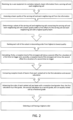
- FIG. 2 is a logic flow diagram illustrating the operation of an exemplary method or methods, resulting from an execution of computer program instructions embodied on a computer readable memory, and/or functions performed by logic implemented in hardware or other means, in accordance with exemplary embodiments, which would be possible.
- Cell quality is based on the RX-LVL of the highest quality beam (RSRP of SS block/CSI-RS), although other measurement quantities are not precluded by the algorithm.
- Cell quality (RX-LVL) may refer to the L3 filtered (e.g. moving average such as defined in LTE) cell quality or cell quality that is not L3 filtered
- the proposed ranking procedure comprises the following three steps.
- the UE determines the highest quality cell (e.g. Cell1) and determines whether any cell from the subset of Cell2 through Cell N qualities is within Offset_1 of the Cell1 (N dB). If no cells are within the Offset_1 (i.e. relative threshold), then the highest quality cell is ranked first and Cell2 through CellN are ranked according to a descending order based on quality. If any of the cells are within the Offset_1 of highest quality cell, then it is considered for second step. All other cells are ranked in descending order based on quality.
- the highest quality cell e.g. Cell1
- N dB Offset_1 of the Cell1
- the UE determines the number of HighQuality beams based on the higher layer (e.g. L2/L3, moving average filter) filtered beam measurements.
- Higher layer beam filtering such as moving average is used to filter L1 measurements (L1 measurement e.g. RSRP may consist of N -L1 samples).
- L1 measurement e.g. RSRP may consist of N -L1 samples.
- moving average filtering previous filtered measurement result is weighted with weight_1 and the latest received measurement result is weighted with weight_2.
- the UE utilizes TTT_1 and Offset_2 to determine if a beam is classified as HighQuality. Offset_2 is compared against the highest quality beam of the highest quality cell, determined in Step 1. Offset_2 may also be same as Offset_1 in Step 1. If a beam RX-LVL > Cell1 RX-LVL - Offset_2 for the duration of (at least, meaning equal time or longer) TTT_1, then it contributes, +1 for example, to the overall cell rank (TTT_1 can be also set to '0' so that e.g. based on one measurement (or the latest measurement or measurement result) the beam contributes the specified value to cell rank such as +1).
- TTT_1 parameter may also be omitted from this step which causes the cell ranking to be based on the latest measurements similarly as TTT_1 would be set to '0'.
- This measurement may be a L1 measurement (i.e. only L1 filtering is applied) or the latest higher layer filtered measurement result.
- a beam RX-LVL > Cell1 RX-LVL - Offset_2 for duration of TTT_2 then it contributes e.g. +2 to the overall cell rank.
- the Offset_2 may not be defined in the algorithm at all and so the Offset_1 would be used instead.
- TTT_2 may not be used i.e. beam would contribute to cell rank single value based on TTT_1.
- the increase in cell ranks would be for each high quality beam, i.e. 2 cells that have highest quality beam inside within the offset_1 are compared based on the number of the high quality beams.
- the first offset can be defined as relative threshold compared to the highest quality beam of the serving cell and neighbor cells and used to determine which cells are considered for ranking based on high quality beams. Offset is expressed as decibels. This value may be signaled by network explicitly e.g. -2,-1,0,1,2,3,4 dBs or given as an factor (integer - 1,0,1,2,3... to be multiplied with a specific number such as 0.5 dB.
- the second offset can be defined as a relative threshold compared to the highest quality beam of serving and neighbor cells and used for determining high quality beams that contribute to an individual cell's overall rank.
- the second offset might not defined and the first offset would be used in place of the second offset.
- the second offset is equal to the first offset.
- the first time-to-trigger is defined as the minimum time duration that a beam reception level (higher layer filtered / non higher layer filtered) must be above the relative threshold defined by Offset_1 (or Offset 2 if defined) so that it contributes to the cell rank.
- the second time-to-trigger is defined as the minimum time duration that a beam reception level (higher layer filtered / non higher layer filtered) must be above the relative threshold defined by Offset_1 (or Offset 2 if defined) so that it contributes different value (e.g. higher) to the cell rank than per the first time-to-trigger.
- Hysteresis value may be defined so that the beam RX-LVL equation can be written as RX-LVL > Cell1 RX-LVL - Offset_1 + H1.
- H1 may be a positive or negative number (expressed in dBs, and can be also zero) and configured by network.
- a beams contribution to cell rank may scale also in following manner: TTT_1 is considered as default value and if the condition for beam RX-LVL > Cell1 RX-LVL - Offset_2 is fulfilled for duration of K*TTT_1 and K is integer then each TTT_1 duration adds +1 to cell rank so that K* +1 would be added to the cell rank. There may be a defined cap for the contribution value e.g. one beam can contribute up to value '5'.
- step 3 the Cells are ranked according to the points assigned in Step 2 in descending order, i.e. cell with the highest number of points is ranked highest. In case two cells are ranked with same value, according to points, the highest quality beam RX-LVL determines the rank between the equally ranked cells.
- a cell is selected where that cell would have the highest final rank. That selecting could be for a conditional handover or for reselecting a cell for camping, where the UE possibly sends some indication to the base station for that cell where the UE receives a transmission from that base station in response.
- the above parameters such as the contribution to cell rank (+1,+1.5,+2) etc. may be predefined in the specification (e.g. 3GPP) or signaled to UE via broadcast (system information) or dedicated signaling (RRC). Also, additionally or alternatively, the different set of parameters may be configured to UE based on which signal is used (e.g. SS block / CSI-RS). Parameters are common for all the cells is not explicitly configured with cell specific values.
- the cell ranking procedure may use in step 2 an alternative or additional interpretation of the configured offset (Offset_1, Offset _2) value so that higher the beam signal reception level (and closer the value to the highest quality beam reception level of all the cells) the higher the contribution value to cell rank.
- Offset_1 is configured with value of 3 dB. A beam with 3 dB lower reception level would contribute +1, a beam with 2 dB lower +2 and beam with 1dB lower or the same would contribute +3. These are only one set of example values. This method can be used in conjunction with the TTT values.
- the network may configure UE to perform the previously described ranking for cells that have been configured for UE for conditional HO. Based on the ranking UE would perform conditional HO to the highest ranked cell when triggers conditions are fulfilled i.e. a cell or multiple cell quality is offset better than current serving. Other conditions are not precluded.
- UE may use the cell ranking when it is configured to report N-highest quality cell to network, or determine which cells UE prioritizes RRM (Radio Resource Management) / mobility measurements.
- RRM Radio Resource Management
- the cell ranking method can be applied for intra-cell mobility measurements / beam management where UE ranks different SS blocks of a serving cell (or multiple cells) for reporting based on the CSI-RS measurements (beams) of specific SS block.
- UE is given the association of specific CSI-RS and SS blocks via broadcast signaling (SIB, system information block) or via dedicated RRC signaling.
- SIB broadcast signaling
- RRC dedicated RRC
- Clause 2 The method of Clause 1, wherein the first offset is defined as relative threshold compared to the highest quality beam of the serving cell and neighbor cells.
- Clause 4 The method of Clause 1, wherein the first time-to-trigger is defined as the minimum time duration that a beam reception level must be above the relative threshold defined by a first and/or second offset.
- Clause 5 The method of Clause 1, wherein the second time-to-trigger is defined as the minimum time duration that a beam reception level (higher layer filtered / non higher layer filtered) must be above the relative threshold defined by Offset_1 (or Offset 2 if defined) so that it contributes different value (e.g. higher) to the cell rank than per the first time-to-trigger.
- the second time-to-trigger is defined as the minimum time duration that a beam reception level (higher layer filtered / non higher layer filtered) must be above the relative threshold defined by Offset_1 (or Offset 2 if defined) so that it contributes different value (e.g. higher) to the cell rank than per the first time-to-trigger.
- Clause 6 The method of Clause 1, wherein the first time-to-trigger is set to 0.
- Clause 7 The method of Clause 1, wherein the reception level of a beam greater than a reception level of the highest quality beam minus a second offset for a duration of a first time-to-trigger or the reception level of a beam is greater than the reception level of the first cell minus the second offset during a time-to-trigger indicates that the beam is a High Quality beam.
- Clause 8 The method of Clause 1, wherein the order is expressed by integers.
- Clause 10 The method of Clause 1, where the selecting is for a conditional handover.
- Clause 11 The method of Clause 1, wherein the selecting is for reselecting a cell for camping.
- Clause 12 A computer program having code comprising instructions to control or carry out the method of any of the preceding Clauses.
- Clause 13 A computer program product embodied on a non-transitory computer-readable medium in which a computer program is stored that, when being executed by a computer, is configured to provide instructions to control or carry out the method of any of Clause 1 through 10.
- Clause 16 The apparatus of Clause 15, wherein the first offset is defined as relative threshold compared to the highest quality beam of the serving cell and neighbor cells.
- Clause 18 The apparatus of Clause 15, wherein the first time-to-trigger is defined as the minimum time duration that a beam reception level must be above the relative threshold defined by a first and/or second offset.
- Clause 19 The apparatus of Clause 15, wherein the second time-to-trigger is defined as the minimum time duration that a beam reception level (higher layer filtered / non higher layer filtered) must be above the relative threshold defined by Offset_1 (or Offset 2 if defined) so that it contributes different value (e.g. higher) to the cell rank than per the first time-to-trigger.
- the second time-to-trigger is defined as the minimum time duration that a beam reception level (higher layer filtered / non higher layer filtered) must be above the relative threshold defined by Offset_1 (or Offset 2 if defined) so that it contributes different value (e.g. higher) to the cell rank than per the first time-to-trigger.
- Clause 20 The apparatus of Clause 15, wherein the first time-to-trigger is set to 0.
- Clause 21 The apparatus of Clause 15, wherein the reception level of a beam greater than a reception level of the highest quality beam minus a second offset for a duration of a first time-to-trigger or the reception level of a beam is greater than the reception level of the first cell minus the second offset during a time-to-trigger indicates that the beam is a High Quality beam.
- Clause 22 The apparatus of Clause 15, wherein the order is expressed by integers.
- Clause 24 The apparatus of Clause 15, wherein the selecting is for a conditional handover.
- Clause 25 The apparatus of Clause 15, wherein the selecting is for reselecting a cell for camping.
Landscapes
- Engineering & Computer Science (AREA)
- Computer Networks & Wireless Communication (AREA)
- Signal Processing (AREA)
- Computer Security & Cryptography (AREA)
- Mobile Radio Communication Systems (AREA)
Abstract
Description
- This invention relates generally to New Radio (NR) and, in particular, to improving performance of intra-frequency cell ranking in a multibeam system in a UE-based mobility environment.
- This section is intended to provide a background or context to the invention disclosed below. The description herein may include concepts that could be pursued, but are not necessarily ones that have been previously conceived, implemented or described. Therefore, unless otherwise explicitly indicated herein, what is described in this section is not prior art to the description in this application and is not admitted to be prior art by inclusion in this section.
- In NR, a UE determines the cell quality level (e.g. RSRP (dBm), RSRQ (dB)) based on beam measurements. These measurement quantities can be based on measurement done on signals encompassed in SS block (in IDLE and in RRC_INACTIVE), namely on SSS and/or PBCH DMRS. The SS block can be transmitted to one beam, the SS block can be superposed on multiple beams, and/or different SS blocks can be sent on different beams. In CONNECTED mode a UE may measure the quality in addition to SS block signals, based on CSI-RS (for beam management, sometimes called intra-cell mobility and /or L3 mobility, or cell level mobility) configured to the UE. In some cases UE may also measure CSI-RS (or any reference signals for mobility purposes also in IDLE/INACTIVE).
- Several papers on the subject have been submitted to 3GPP RAN2#98 (May 2017) but, according to the Chairman notes, were not treated (a related discussion was expected at the next RAN2 meeting). For example, Huawei (in R2-1704896 Derivation of cell quality in IDLE/INACTIVE, Huawei, HiSilicon, 3GPP TSG-RAN WG2 Meeting #98, Hangzhou, China, 15-19 May 2017) proposed a method to derive cell quality in RRC_Idle/RRC_Inactive mode, wherein a method would be to simply average multiple beams to derive cell-level quality. However, by performing such a step, information that would be lost includes the per beam quality and the information about the actual number of beams (or "good beams") per cell, which are of paramount importance and not neglected in the procedure disclosed by the invention herein.
- Ericsson (in R2-1705436 Derivation of cell quality in IDLE/INACTIVE, Ericsson, 3GPP TSG-RAN WG2 Meeting #98, Hangzhou, China, 15-19 May 2017) also touched upon the topic, but without proposing any specific procedure, focusing more on the value of N (i.e. the number of beams) and suggesting considering a relative threshold (i.e. offset), rather than an absolute threshold.
- The current invention moves beyond the current techniques and/or materials.
- Acronyms or abbreviations that may be found in the specification and/or the drawing figures are defined within the context of this disclosure or as follows below:
3GPP Third Generation Partnership Project 5G 5th Generation ACK Acknowledgement AR Augmented Reality CSI - RS Channel State Information-Reference Signals DCI Downlink Control Information DL Downlink DL-SCH Downlink Shared Channel DMRS Demodulation Reference Signal eNB or eNodeB base station, evolved Node B FFS For Further Study gNB NR/5G Node B HO Handover HARQ Hybrid Automatic Repeat Request LTE Long Term Evolution LTE-A Long Term Evolution - Advanced LVL Level MBB Mobile Broadband MME Mobility Management Entity MSG Message NACK Negative Acknowledgement NCE Network Control Entity NR New Radio NW Network OFDM Orthogonal Frequency Division Multiplexing PBCH Physical Broadcast Channel PDCCH Physical Downlink Control Channel PDSCH Physical Downlink Shared Channel PRACH Physical Random Channel PRB Physical Resource Block PSS Primary Synchronization Signal PUCCH Physical Uplink Control Channel PUSCH Physical Uplink Shared Channel RACH Random Access Channel RA Resource Allocation RAR Random Access Response RAT Radio Access Technology RB Resource Block Rel Release RE Resource Element RS Reference Signal RSRP Reference Signal Received Power RSRQ Reference Signal Received Quality RRC Radio Resource Control RV Redundancy Version RX Reception SS Synchronization Signal SSS Secondary Synchronization Signal TB Transport Block TS Technical Specification TRP Transmission reception point TTI Transmission Time Interval TTT Time To Trigger UE User Equipment TX Transmission UCI Uplink Control Information UE User Equipment UL Uplink - Various aspects of examples of the invention are set out in the claims.
- According to a first aspect of the present invention, an apparatus comprising at least one processor and at least one memory including computer program code, wherein the at least one memory and the computer code are configured to, with the at least one processor, cause the apparatus to at least: receive beam information from a serving cell and each neighboring cell; assess a beam quality of the serving cell and each neighboring cell from the information; determine a subset of the serving cell and neighboring cells comprising the serving cell and each neighboring cell with a beam quality within a first offset of the serving cell and each neighboring cell with a highest quality beam; rank each cell of the subset in descending order from highest to lowest quality; calculate, firstly, a reception level of the strongest cell minus a second offset for a duration of a first time-to-trigger and, secondly, a reception level of the strongest cell minus the second offset for a duration of a second time-to-trigger; compare reception levels of beams from each ranked cell to the first calculation and second calculation; advance the order of each ranked cell per beam with a reception level greater than: the first calculation by a first grade, the second calculation by a second grade, and an equally ranked cell by a fractional grade; select a cell having a highest order.
- According to a second aspect of the present invention, a method comprising: receiving, by a user equipment in a wireless network, beam information from a serving cell and each neighboring cell; assessing a beam quality of the serving cell and each neighboring cell from the information; determining a subset of the serving cell and neighboring cells comprising the serving cell and each neighboring cell with a beam quality within a first offset of the serving cell and each neighboring cell with a highest quality beam; ranking each cell of the subset in descending order from highest to lowest quality; calculating, firstly, a reception level of the strongest cell minus a second offset for a duration of a first time-to-trigger and, secondly, a reception level of the strongest cell minus the second offset for a duration of a second time-to-trigger; comparing reception levels of beams from each ranked cell to the first calculation and second calculation; advancing the order of each ranked cell per beam with a reception level greater than: the first calculation by a first grade, the second calculation by a second grade, and an equally ranked cell by a fractional grade; selecting a cell having a highest order.
- According to a third aspect of the present invention, a computer program product comprising a non-transitory computer-readable medium bearing computer program code embodied therein for use with a computer, the computer program code comprising code for: receiving, by a user equipment in a wireless network, beam information from a serving cell and each neighboring cell; assessing a beam quality of the serving cell and each neighboring cell from the information; determining a subset of the serving cell and neighboring cells comprising the serving cell and each neighboring cell with a beam quality within a first offset of the serving cell and each neighboring cell with a highest quality beam; ranking each cell of the subset in descending order from highest to lowest quality; calculating, firstly, a reception level of the strongest cell minus a second offset for a duration of a first time-to-trigger and, secondly, a reception level of the strongest cell minus the second offset for a duration of a second time-to-trigger; comparing reception levels of beams from each ranked cell to the first calculation and second calculation; advancing the order of each ranked cell per beam with a reception level greater than: the first calculation by a first grade, the second calculation by a second grade, and an equally ranked cell by a fractional grade; selecting a cell having a highest order.
- In the attached Drawing Figures:
-
FIG. 1 is a block diagram of an exemplary system in which the exemplary embodiments may be practiced; and -
FIG. 2 is a logic flow diagram illustrating the operation of an exemplary method or methods, resulting from an execution of computer program instructions embodied on a computer readable memory, and/or functions performed by logic implemented in hardware or other means, in accordance with exemplary embodiments, which would be possible. - The word "exemplary" is used herein to mean "serving as an example, instance, or illustration." Any embodiment described herein as "exemplary" is not necessarily to be construed as preferred or advantageous over other embodiments. All of the embodiments described in this Detailed Description are exemplary embodiments provided to enable persons skilled in the art to make or use the invention and not to limit the scope of the invention which is defined by the claims.
- The exemplary embodiments herein describe how a UE would perform intra-frequency cell ranking in multi beam system in UE based mobility. Typically, a UE based mobility has been a feature of IDLE mode (e.g. in LTE), but now this invention proposes that a UE would perform it also in INACTIVE mode.
- Mechanisms described in the invention are also applicable for CONNECTED mode operation, e.g. when UE is configured to perform "conditional HO" (i.e. the HO with an early HO command and the condition which needs to be fulfilled in order to execute the actual HO) and has multiple cells with high quality beams to select from. This may be a non-trivial task to properly choose the best cell instantaneously by measuring and weighting the beams.
- The following cell reselection methods, as specified in TS 36.304, and are most likely applicable for NR as well. A UE performs cell reselection based on the corresponding parameters broadcast while the UE is camping on a cell (receives information from network, e.g. system information and paging) in NR:
- Intra-frequency reselection is based on ranking of cells;
- Inter-frequency reselection is based on absolute priorities;
- Inter-RAT reselection can be also based on absolute priorities;
- Frequency specific cell reselection parameters common to all neighboring cells on a frequency;
- Service-specific prioritization, noting that for NR, it is FFS for which services the service specific prioritization is applied and how it could be applied for the case of network slices;
- A concept of neighbor cell lists and black cell lists;
- Speed dependent cell reselection.
- In multi-beam operations, measurement quantity of a cell is derived from N best beams (N -best referring to the N highest quality beams based on measurement quantity such as RSRP, or RSRQ, SINR etc.) corresponding to the same cell where the value of N can be configured to 1 or more than 1. It is FFS on the details of filtering to be applied (e.g. for the case N = 1, the best beam is filtered by a single filter as the best beam changes) and whether to only consider beams above a threshold (so-called "good beams").
- For a cell ranking procedure in multiple beam system, a UE performs cell ranking between cells which RX-LVL (where RX-LVL is determined e.g. based on the RSRP, RSRQ or the like) are within a configured relative offset compared to the cell with highest RX-LVL by considering the contribution factor of number of high quality beams on each cell, where the high quality beams are determined based on NW configured parameters (e.g. another offset value). Beam quality evaluation may apply different filtering scheme compared to cell quality evaluation. The contribution factor is calculated based on the observed quality based on the configured threshold signal levels and time window. The cell with the higher number of high quality beams may rank that certain cell higher
- Turning to
FIG. 1 , this figure shows a block diagram of one possible and non-limiting exemplary system in which the exemplary embodiments may be practiced. InFIG. 1 , a user equipment (UE) 110 is in wireless communication with awireless network 100. A UE is a wireless, typically mobile device that can access a wireless network. The UE 110 includes one ormore processors 120, one ormore memories 125, and one ormore transceivers 130 interconnected through one ormore buses 127. Each of the one ormore transceivers 130 includes a receiver, Rx, 132 and a transmitter, Tx, 133. The one ormore buses 127 may be address, data, or control buses, and may include any interconnection mechanism, such as a series of lines on a motherboard or integrated circuit, fiber optics or other optical communication equipment, and the like. The one ormore transceivers 130 are connected to one ormore antennas 128. The one ormore memories 125 includecomputer program code 123. The UE 110 includes a YYY module 140, comprising one of or both parts 140-1 and/or 140-2, which may be implemented in a number of ways. The YYY module 140 may be implemented in hardware as YYY module 140-1, such as being implemented as part of the one ormore processors 120. The YYY module 140-1 may be implemented also as an integrated circuit or through other hardware such as a programmable gate array. In another example, the YYY module 140 may be implemented as YYY module 140-2, which is implemented ascomputer program code 123 and is executed by the one ormore processors 120. For instance, the one ormore memories 125 and thecomputer program code 123 may be configured to, with the one ormore processors 120, cause theuser equipment 110 to perform one or more of the operations as described herein. The UE 110 communicates with gNB 170 via awireless link 111. - The gNB (NR/5G Node B but possibly an evolved NodeB) 170 is a base station (e.g., for LTE, long term evolution) of the set of base stations available to the UE 110 that provides access by wireless devices such as the UE 110 to the
wireless network 100. The gNB 170 includes one ormore processors 152, one ormore memories 155, one or more network interfaces (N/W I/F(s)) 161, and one ormore transceivers 160 interconnected through one ormore buses 157. Each of the one ormore transceivers 160 includes a receiver, Rx, 162 and a transmitter, Tx, 163. The one ormore transceivers 160 are connected to one ormore antennas 158. The one ormore memories 155 include computer program code 153. ThegNB 170 includes a ZZZ module 150, comprising one of or both parts 150-1 and/or 150-2, which may be implemented in a number of ways. The ZZZ module 150 may be implemented in hardware as ZZZ module 150-1, such as being implemented as part of the one ormore processors 152. The ZZZ module 150-1 may be implemented also as an integrated circuit or through other hardware such as a programmable gate array. In another example, the ZZZ module 150 may be implemented as ZZZ module 150-2, which is implemented as computer program code 153 and is executed by the one ormore processors 152. For instance, the one ormore memories 155 and the computer program code 153 are configured to, with the one ormore processors 152, cause thegNB 170 to perform one or more of the operations as described herein. The one ormore network interfaces 161 communicate over a network such as via thelinks link 176 may be wired or wireless or both and may implement, e.g., an X2 interface. - The one or
more buses 157 may be address, data, or control buses, and may include any interconnection mechanism, such as a series of lines on a motherboard or integrated circuit, fiber optics or other optical communication equipment, wireless channels, and the like. For example, the one ormore transceivers 160 may be implemented as a remote radio head (RRH) 195, with the other elements of thegNB 170 being physically in a different location from the RRH, and the one ormore buses 157 could be implemented in part as fiber optic cable to connect the other elements of thegNB 170 to theRRH 195. - It is noted that description herein indicates that "cells" perform functions, but it should be clear that the gNB that forms the cell will perform the functions. The cell makes up part of a gNB. That is, there can be multiple cells per gNB.
- The
wireless network 100 may include a network control element (NCE) 190 that may include MME (Mobility Management Entity)/SGW (Serving Gateway) functionality, and which provides connectivity with a further network, such as a telephone network and/or a data communications network (e.g., the Internet). ThegNB 170 is coupled via alink 131 to theNCE 190. Thelink 131 may be implemented as, e.g., an S1 interface. TheNCE 190 includes one ormore processors 175, one ormore memories 171, and one or more network interfaces (N/W I/F(s)) 180, interconnected through one ormore buses 185. The one ormore memories 171 includecomputer program code 173. The one ormore memories 171 and thecomputer program code 173 are configured to, with the one ormore processors 175, cause theNCE 190 to perform one or more operations. - The
wireless network 100 may implement network virtualization, which is the process of combining hardware and software network resources and network functionality into a single, software-based administrative entity, a virtual network. Network virtualization involves platform virtualization, often combined with resource virtualization. Network virtualization is categorized as either external, combining many networks, or parts of networks, into a virtual unit, or internal, providing network-like functionality to software containers on a single system. Note that the virtualized entities that result from the network virtualization are still implemented, at some level, using hardware such asprocessors memories - The computer
readable memories readable memories processors processors UE 110,gNB 170, and other functions as described herein. - In general, the various embodiments of the
user equipment 110 can include, but are not limited to, cellular telephones such as smart phones, tablets, personal digital assistants (PDAs) having wireless communication capabilities, portable computers having wireless communication capabilities, image capture devices such as digital cameras having wireless communication capabilities, gaming devices having wireless communication capabilities, music storage and playback appliances having wireless communication capabilities, Internet appliances permitting wireless Internet access and browsing, tablets with wireless communication capabilities, as well as portable units or terminals that incorporate combinations of such functions. - Embodiments herein may be implemented in software (executed by one or more processors), hardware (e.g., an application specific integrated circuit), or a combination of software and hardware. In an example of an embodiment, the software (e.g., application logic, an instruction set) is maintained on any one of various conventional computer-readable media. In the context of this document, a "computer-readable medium" may be any media or means that can contain, store, communicate, propagate or transport the instructions for use by or in connection with an instruction execution system, apparatus, or device, such as a computer, with one example of a computer described and depicted, e.g., in
FIG. 1 . A computer-readable medium may comprise a computer-readable storage medium or other device that may be any media or means that can contain or store the instructions for use by or in connection with an instruction execution system, apparatus, or device, such as a computer. - The current architecture in LTE networks is fully distributed in the radio and fully centralized in the core network. The low latency requires bringing the content close to the radio which leads to local break out and multi-access edge computing (MEC). 5G may use edge cloud and local cloud architecture. Edge computing covers a wide range of technologies such as wireless sensor networks, mobile data acquisition, mobile signature analysis, cooperative distributed peer-to-peer ad hoc networking and processing also classifiable as local cloud/fog computing and grid/mesh computing, dew computing, mobile edge computing, cloudlet, distributed data storage and retrieval, autonomic self-healing networks, remote cloud services and augmented reality. In radio communications, using edge cloud may mean node operations to be carried out, at least partly, in a server, host or node operationally coupled to a remote radio head or base station comprising radio parts. It is also possible that node operations will be distributed among a plurality of servers, nodes or hosts. It should also be understood that the distribution of labor between core network operations and base station operations may differ from that of the LTE or even be non-existent. Some other technology advancements probably to be used are Software-Defined Networking (SDN), Big Data, and all-IP, which may change the way networks are being constructed and managed.
- One possible manner to carry out embodiments described herein is with an edge cloud using a distributed computing system. An exemplary embodiment comprises a radio node connected to a server. Exemplary embodiments implementing the system allow the edge cloud server and the radio node as stand-alone apparatuses communicating with each other via a radio path or via a wired connection or they may be located in a same entity communicating via a wired connection.
-
FIG. 2 is a logic flow diagram illustrating the operation of an exemplary method or methods, resulting from an execution of computer program instructions embodied on a computer readable memory, and/or functions performed by logic implemented in hardware or other means, in accordance with exemplary embodiments, which would be possible. Cell quality (RX-LVL) is based on the RX-LVL of the highest quality beam (RSRP of SS block/CSI-RS), although other measurement quantities are not precluded by the algorithm. Cell quality (RX-LVL) may refer to the L3 filtered (e.g. moving average such as defined in LTE) cell quality or cell quality that is not L3 filtered - The proposed ranking procedure comprises the following three steps.
- In step 1, the UE determines the highest quality cell (e.g. Cell1) and determines whether any cell from the subset of Cell2 through CellN qualities is within Offset_1 of the Cell1 (N dB). If no cells are within the Offset_1 (i.e. relative threshold), then the highest quality cell is ranked first and Cell2 through CellN are ranked according to a descending order based on quality. If any of the cells are within the Offset_1 of highest quality cell, then it is considered for second step. All other cells are ranked in descending order based on quality.
- In step 2, for all the cells that are within the Offset_1 in Step 1, the UE determines the number of HighQuality beams based on the higher layer (e.g. L2/L3, moving average filter) filtered beam measurements. Higher layer beam filtering, such as moving average is used to filter L1 measurements (L1 measurement e.g. RSRP may consist of N -L1 samples). In moving average filtering, previous filtered measurement result is weighted with weight_1 and the latest received measurement result is weighted with weight_2. As an example, weights can be selected so that weight_1 = alpha and weight_2 = 1- alpha. Filtering parameters that are used to calculate alpha may be configurable by network.
- The UE utilizes TTT_1 and Offset_2 to determine if a beam is classified as HighQuality. Offset_2 is compared against the highest quality beam of the highest quality cell, determined in Step 1. Offset_2 may also be same as Offset_1 in Step 1. If a beam RX-LVL > Cell1 RX-LVL - Offset_2 for the duration of (at least, meaning equal time or longer) TTT_1, then it contributes, +1 for example, to the overall cell rank (TTT_1 can be also set to '0' so that e.g. based on one measurement (or the latest measurement or measurement result) the beam contributes the specified value to cell rank such as +1). TTT_1 parameter may also be omitted from this step which causes the cell ranking to be based on the latest measurements similarly as TTT_1 would be set to '0'. This measurement may be a L1 measurement (i.e. only L1 filtering is applied) or the latest higher layer filtered measurement result. Additionally, if a beam RX-LVL > Cell1 RX-LVL - Offset_2 for duration of TTT_2, then it contributes e.g. +2 to the overall cell rank. Note that the Offset_2 may not be defined in the algorithm at all and so the Offset_1 would be used instead. In similar manner TTT_2 may not be used i.e. beam would contribute to cell rank single value based on TTT_1. The increase in cell ranks would be for each high quality beam, i.e. 2 cells that have highest quality beam inside within the offset_1 are compared based on the number of the high quality beams.
- The first offset can be defined as relative threshold compared to the highest quality beam of the serving cell and neighbor cells and used to determine which cells are considered for ranking based on high quality beams. Offset is expressed as decibels. This value may be signaled by network explicitly e.g. -2,-1,0,1,2,3,4 dBs or given as an factor (integer - 1,0,1,2,3... to be multiplied with a specific number such as 0.5 dB.
- The second offset can be defined as a relative threshold compared to the highest quality beam of serving and neighbor cells and used for determining high quality beams that contribute to an individual cell's overall rank. Alternatively, the second offset might not defined and the first offset would be used in place of the second offset. As another alternative, the second offset is equal to the first offset.
- The first time-to-trigger is defined as the minimum time duration that a beam reception level (higher layer filtered / non higher layer filtered) must be above the relative threshold defined by Offset_1 (or Offset 2 if defined) so that it contributes to the cell rank.
- The second time-to-trigger is defined as the minimum time duration that a beam reception level (higher layer filtered / non higher layer filtered) must be above the relative threshold defined by Offset_1 (or Offset 2 if defined) so that it contributes different value (e.g. higher) to the cell rank than per the first time-to-trigger.
- In one further example, a specific Hysteresis value (H1) may be defined so that the beam RX-LVL equation can be written as RX-LVL > Cell1 RX-LVL - Offset_1 + H1. H1 may be a positive or negative number (expressed in dBs, and can be also zero) and configured by network.
- In a variant, a beams contribution to cell rank may scale also in following manner: TTT_1 is considered as default value and if the condition for beam RX-LVL > Cell1 RX-LVL - Offset_2 is fulfilled for duration of K*TTT_1 and K is integer then each TTT_1 duration adds +1 to cell rank so that K* +1 would be added to the cell rank. There may be a defined cap for the contribution value e.g. one beam can contribute up to value '5'.
- In step 3, the Cells are ranked according to the points assigned in Step 2 in descending order, i.e. cell with the highest number of points is ranked highest. In case two cells are ranked with same value, according to points, the highest quality beam RX-LVL determines the rank between the equally ranked cells.
- Thus, a cell is selected where that cell would have the highest final rank. That selecting could be for a conditional handover or for reselecting a cell for camping, where the UE possibly sends some indication to the base station for that cell where the UE receives a transmission from that base station in response.
- The above parameters such as the contribution to cell rank (+1,+1.5,+2) etc. may be predefined in the specification (e.g. 3GPP) or signaled to UE via broadcast (system information) or dedicated signaling (RRC). Also, additionally or alternatively, the different set of parameters may be configured to UE based on which signal is used (e.g. SS block / CSI-RS). Parameters are common for all the cells is not explicitly configured with cell specific values.
- In a variant, the cell ranking procedure may use in step 2 an alternative or additional interpretation of the configured offset (Offset_1, Offset _2) value so that higher the beam signal reception level (and closer the value to the highest quality beam reception level of all the cells) the higher the contribution value to cell rank. As an example, Offset_1 is configured with value of 3 dB. A beam with 3 dB lower reception level would contribute +1, a beam with 2 dB lower +2 and beam with 1dB lower or the same would contribute +3. These are only one set of example values. This method can be used in conjunction with the TTT values.
- In one example, the network may configure UE to perform the previously described ranking for cells that have been configured for UE for conditional HO. Based on the ranking UE would perform conditional HO to the highest ranked cell when triggers conditions are fulfilled i.e. a cell or multiple cell quality is offset better than current serving. Other conditions are not precluded.
- In yet another example, UE may use the cell ranking when it is configured to report N-highest quality cell to network, or determine which cells UE prioritizes RRM (Radio Resource Management) / mobility measurements.
- In yet another example, the cell ranking method can be applied for intra-cell mobility measurements / beam management where UE ranks different SS blocks of a serving cell (or multiple cells) for reporting based on the CSI-RS measurements (beams) of specific SS block. UE is given the association of specific CSI-RS and SS blocks via broadcast signaling (SIB, system information block) or via dedicated RRC signaling.
- Although various aspects are set out above, other aspects comprise other combinations of features from the described embodiments, and not solely the combinations described above. If desired, the different functions discussed herein may be performed in a different order and/or concurrently with each other. Furthermore, if desired, one or more of the above-described functions may be optional or may be combined.
- Although various aspects of the invention are set out in the independent claims, other aspects of the invention comprise other combinations of features from the described embodiments and/or the dependent claims with the features of the independent claims, and not solely the combinations explicitly set out in the claims.
- Without in any way limiting the scope, interpretation, or application of the claims appearing below, an advantage or technical effect of one or more of the exemplary embodiments disclosed herein is the added functionality.
- It is also noted herein that while the above describes example embodiments of the invention, these descriptions should not be viewed in a limiting sense. Rather, there are several variations and modifications which may be made without departing from the scope of the present invention.
- Clause 1. A method comprising:
- receiving, by a user equipment in a wireless network, beam information from a serving cell and each neighboring cell;
- assessing a beam quality of the serving cell and each neighboring cell from the information;
- determining a subset of the serving cell and neighboring cells comprising the serving cell and each neighboring cell with a beam quality within a first offset of the serving cell and each neighboring cell with a highest quality beam;
- ranking each cell of the subset in descending order from highest to lowest quality;
- calculating, firstly, a reception level of the strongest cell minus a second offset for a duration of a first time-to-trigger and, secondly, a reception level of the strongest cell minus the second offset for a duration of a second time-to-trigger;
- comparing reception levels of beams from each ranked cell to the first calculation and second calculation;
- advancing the order of each ranked cell per beam with a reception level greater than:
- the first calculation by a first grade,
- the second calculation by a second grade, and
- an equally ranked cell by a fractional grade;
- selecting a cell having a highest order.
- Clause 2. The method of Clause 1, wherein the first offset is defined as relative threshold compared to the highest quality beam of the serving cell and neighbor cells.
- Clause 3. The method of Clause 1, wherein
- the second offset is defined as a relative threshold compared to the highest quality beam of serving and neighbor cells and used for determining high quality beams that contribute to an individual cell's overall rank,
- the second offset is not defined and the first offset is used in place of the second offset, or
- the second offset is equal to the first offset.
- Clause 4. The method of Clause 1, wherein the first time-to-trigger is defined as the minimum time duration that a beam reception level must be above the relative threshold defined by a first and/or second offset.
- Clause 5. The method of Clause 1, wherein the second time-to-trigger is defined as the minimum time duration that a beam reception level (higher layer filtered / non higher layer filtered) must be above the relative threshold defined by Offset_1 (or Offset 2 if defined) so that it contributes different value (e.g. higher) to the cell rank than per the first time-to-trigger.
- Clause 6. The method of Clause 1, wherein the first time-to-trigger is set to 0.
- Clause 7. The method of Clause 1, wherein the reception level of a beam greater than a reception level of the highest quality beam minus a second offset for a duration of a first time-to-trigger or the reception level of a beam is greater than the reception level of the first cell minus the second offset during a time-to-trigger indicates that the beam is a High Quality beam.
- Clause 8. The method of Clause 1, wherein the order is expressed by integers.
- Clause 9. The method of Clause 1, wherein
- the second grade is greater than the first grade, and
- the fractional grade is less than the first grade and less than the second grade.
- Clause 10. The method of Clause 1, where the selecting is for a conditional handover.
- Clause 11. The method of Clause 1, wherein the selecting is for reselecting a cell for camping.
- Clause 12. A computer program having code comprising instructions to control or carry out the method of any of the preceding Clauses.
- Clause 13. A computer program product embodied on a non-transitory computer-readable medium in which a computer program is stored that, when being executed by a computer, is configured to provide instructions to control or carry out the method of any of Clause 1 through 10.
- Clause 14. An apparatus comprising:
- mean for receiving, by a user equipment in a wireless network, beam information from a serving cell and each neighboring cell;
- means for assessing a beam quality of the serving cell and each neighboring cell from the information;
- means for determining a subset of the serving cell and neighboring cells comprising the serving cell and each neighboring cell with a beam quality within a first offset of a the serving cell and each neighboring cell with a highest quality beam;
- means for ranking each cell of the subset in descending order from highest to lowest quality;
- means for calculating, firstly, a reception level of the strongest cell minus a second offset for a duration of a first time-to-trigger and, secondly, a reception level of the strongest cell minus the second offset for a duration of a second time-to-trigger;
- means for comparing reception levels of beams from each ranked cell to the first calculation and second calculation;
- means for advancing the order of each ranked cell per beam with a reception level greater than:
- the first calculation by a first grade,
- the second calculation by a second grade, and
- an equally ranked cell by a fractional grade;
- means for selecting a cell having a highest order.
- Clause 15. An apparatus comprising:
- at least one processor and at least one memory including computer program code, wherein the at least one memory and the computer code are configured to, with the at least one processor, cause the apparatus to at least:
- receive beam information from a serving cell and each neighboring cell;
- assess a beam quality of the serving cell and each neighboring cell from the information;
- determine a subset of the serving cell and neighboring cells comprising the serving cell and each neighboring cell with a beam quality within a first offset of the serving cell and each neighboring cell with a highest quality beam;
- rank each cell of the subset in descending order from highest to lowest quality;
- calculate, firstly, a reception level of the strongest cell minus a second offset for a duration of a first time-to-trigger and, secondly, a reception level of the strongest cell minus the second offset for a duration of a second time-to-trigger;
- compare reception levels of beams from each ranked cell to the first calculation and second calculation;
- advance the order of each ranked cell per beam with a reception level greater than:
- the first calculation by a first grade,
- the second calculation by a second grade, and
- an equally ranked cell by a fractional grade;
- select a cell having a highest order.
- Clause 16. The apparatus of Clause 15, wherein the first offset is defined as relative threshold compared to the highest quality beam of the serving cell and neighbor cells.
- Clause 17. The apparatus of Clause 15, wherein
- the second offset is defined as a relative threshold compared to the highest quality beam of serving and neighbor cells and used for determining high quality beams that contribute to an individual cell's overall rank,
- the second offset is not defined and the first offset is used in place of the second offset, or
- the second offset is equal to the first offset.
- Clause 18. The apparatus of Clause 15, wherein the first time-to-trigger is defined as the minimum time duration that a beam reception level must be above the relative threshold defined by a first and/or second offset.
- Clause 19. The apparatus of Clause 15, wherein the second time-to-trigger is defined as the minimum time duration that a beam reception level (higher layer filtered / non higher layer filtered) must be above the relative threshold defined by Offset_1 (or Offset 2 if defined) so that it contributes different value (e.g. higher) to the cell rank than per the first time-to-trigger.
- Clause 20. The apparatus of Clause 15, wherein the first time-to-trigger is set to 0.
- Clause 21. The apparatus of Clause 15, wherein the reception level of a beam greater than a reception level of the highest quality beam minus a second offset for a duration of a first time-to-trigger or the reception level of a beam is greater than the reception level of the first cell minus the second offset during a time-to-trigger indicates that the beam is a High Quality beam.
- Clause 22. The apparatus of Clause 15, wherein the order is expressed by integers.
- Clause 23. The apparatus of Clause 15, wherein
- the second grade is greater than the first grade, and
- the fractional grade is less than the first grade and less than the second grade.
- Clause 24. The apparatus of Clause 15, wherein the selecting is for a conditional handover.
- Clause 25. The apparatus of Clause 15, wherein the selecting is for reselecting a cell for camping.
Claims (15)
- An apparatus, comprising:means for performing, by a user equipment for a cell ranking procedure in a multiple beam system, cell ranking between cells which reception level are within a configured relative offset compared to a cell with the highest reception level by considering a contribution factor of a number of high quality beams on each cell, wherein the high quality beams are determined based on network configured parameters and the contribution factor is calculated based on an observed quality based on configured threshold signal levels and a time window; andmeans for ranking, by the user equipment, a cell with a higher number of high quality beams higher.
- The apparatus of claim 1, wherein the reception level is determined based at least on reference signal received power or reference signal received quality.
- The apparatus of claim 1 or claim 2, wherein a different filtering scheme is applied for beam quality evaluation compared to cell quality evaluation.
- The apparatus of any of claims 1 to 3, wherein the network configured parameters comprise another offset value.
- The apparatus of any of claims 1 to 4, wherein the configured relative offset is a first offset and defined as a relative threshold compared to a highest quality beam of a serving cell and neighbor cells.
- The apparatus of any of claims 1 to 5, wherein the network configured parameters comprise a second offset, andthe second offset is defined as a relative threshold compared to a highest quality beam of a serving and neighbor cells and used for determining high quality beams that contribute to an individual cell's overall rank;the second offset is not defined and a first offset is used in place of the second offset; orthe second offset is equal to the first offset.
- The apparatus of any of claims 1 to 6. further comprising calculating, firstly, a reception level of the strongest cell minus a second offset for a duration of a first time-to-trigger and, secondly, a reception level of the strongest cell minus a second offset for a duration of a second time-to-trigger.
- The apparatus of claim 7, wherein the first time-to-trigger is defined as the minimum time duration that a beam reception level must be above a relative threshold defined by a first and/or second offset.
- The apparatus of claim 7 or claim 8, wherein the second time-to-trigger is defined as the minimum time duration that a beam reception level (higher layer filtered / non higher layer filtered) must be above a relative threshold defined bya first offset, or a second offset if defined, so that it contributes different value to the cell rank than per the first time-to-trigger.
- The apparatus of any of claims 1 to 9, further comprising: determining, for all cells that are within a first offset, a number of high quality beams based on a higher layer filtered beam measurements.
- The apparatus of any of claims 1 to 10, further comprising: selecting a cell with a highest rank for a conditional handover or for reselecting a cell for camping.
- A method, comprising:performing, by a user equipment for a cell ranking procedure in a multiple beam system, cell ranking between cells which reception level are within a configured relative offset compared to a cell with the highest reception level by considering a contribution factor of a number of high quality beams on each cell, wherein the high quality beams are determined based on network configured parameters and the contribution factor is calculated based on an observed quality based on configured threshold signal levels and a time window; andranking, by the user equipment, a cell with a higher number of high quality beams higher.
- The method of claim 12, wherein the reception level is determined based at least on reference signal received power or reference signal received quality.
- The method of claim 12 or claim 13, wherein a different filtering scheme is applied for beam quality evaluation compared to cell quality evaluation.
- A computer program having code comprising instructions to control or carry out the method of any of claims 12 to 14.
Applications Claiming Priority (3)
| Application Number | Priority Date | Filing Date | Title |
|---|---|---|---|
| US201762524834P | 2017-06-26 | 2017-06-26 | |
| EP18825195.3A EP3646474A4 (en) | 2017-06-26 | 2018-06-20 | CELL STRING IN A MULTI-BEAM SYSTEM |
| PCT/IB2018/054563 WO2019003059A1 (en) | 2017-06-26 | 2018-06-20 | Cell ranking in multi beam system |
Related Parent Applications (1)
| Application Number | Title | Priority Date | Filing Date |
|---|---|---|---|
| EP18825195.3A Division EP3646474A4 (en) | 2017-06-26 | 2018-06-20 | CELL STRING IN A MULTI-BEAM SYSTEM |
Publications (2)
| Publication Number | Publication Date |
|---|---|
| EP4462885A2 true EP4462885A2 (en) | 2024-11-13 |
| EP4462885A3 EP4462885A3 (en) | 2025-05-14 |
Family
ID=64741225
Family Applications (2)
| Application Number | Title | Priority Date | Filing Date |
|---|---|---|---|
| EP24202693.8A Pending EP4462885A3 (en) | 2017-06-26 | 2018-06-20 | Cell ranking in multi beam system |
| EP18825195.3A Withdrawn EP3646474A4 (en) | 2017-06-26 | 2018-06-20 | CELL STRING IN A MULTI-BEAM SYSTEM |
Family Applications After (1)
| Application Number | Title | Priority Date | Filing Date |
|---|---|---|---|
| EP18825195.3A Withdrawn EP3646474A4 (en) | 2017-06-26 | 2018-06-20 | CELL STRING IN A MULTI-BEAM SYSTEM |
Country Status (4)
| Country | Link |
|---|---|
| US (1) | US11856467B2 (en) |
| EP (2) | EP4462885A3 (en) |
| CN (1) | CN110741564A (en) |
| WO (1) | WO2019003059A1 (en) |
Families Citing this family (18)
| Publication number | Priority date | Publication date | Assignee | Title |
|---|---|---|---|---|
| US11122497B2 (en) * | 2017-05-04 | 2021-09-14 | Samsung Electronics Co., Ltd. | Method and apparatus for SS block index and timing indication in wireless systems |
| ES2965197T3 (en) * | 2017-08-01 | 2024-04-11 | Ericsson Telefon Ab L M | Method, base station and user equipment for selecting a set of beams to be monitored by said UE |
| EP3777337A1 (en) * | 2018-04-04 | 2021-02-17 | Telefonaktiebolaget Lm Ericsson (Publ) | Performing cell measurements |
| WO2020036379A1 (en) * | 2018-08-16 | 2020-02-20 | Lg Electronics Inc. | Method for deriving cell quality and device supporting the same |
| WO2020041196A1 (en) * | 2018-08-20 | 2020-02-27 | Intel Corporation | Fast initial acquisition by transmitting non-orthogonal synchronization signal blocks in 5g new radio |
| US11096079B2 (en) * | 2018-10-29 | 2021-08-17 | Apple Inc. | Cell measurements using configured reference signals while in RRC inactive mode |
| WO2020193789A1 (en) * | 2019-03-28 | 2020-10-01 | Telefonaktiebolaget Lm Ericsson (Publ) | Method and apparatus for cell selection in a wireless communication network |
| CN112399488B (en) | 2019-08-14 | 2024-12-10 | 苹果公司 | Continuous conditional switching |
| CN114731733B (en) | 2020-02-13 | 2024-07-26 | 中兴通讯股份有限公司 | Cell reselection technique |
| EP4128566A1 (en) * | 2020-03-31 | 2023-02-08 | Nokia Technologies Oy | Method for utilizing beam-specific cell-individual offsets in a user equipment |
| EP4144128A1 (en) | 2020-04-30 | 2023-03-08 | Nokia Solutions and Networks Oy | Conditional handover with beamforming and son information |
| EP4150970A1 (en) * | 2020-05-14 | 2023-03-22 | Nokia Technologies Oy | Cell selection |
| EP3920574B1 (en) | 2020-06-04 | 2024-09-11 | Nokia Technologies Oy | Storing beam related information of used beam at the time of initiating the time-to-trigger procedure |
| US20240008018A1 (en) * | 2020-12-03 | 2024-01-04 | Nokia Solutions And Networks Oy | Method, Apparatus and Computer Program for Machine Learning-Assisted Beams Coordinated Scheduling in 5G and Beyond |
| WO2023130363A1 (en) * | 2022-01-07 | 2023-07-13 | Nokia Shanghai Bell Co., Ltd. | Relaxation of measurements for failure detection |
| US12267118B2 (en) * | 2022-02-08 | 2025-04-01 | Rakuten Symphony, Inc. | Apparatus and method for serving cell identification |
| GB2642997A (en) * | 2024-07-26 | 2026-02-04 | Nokia Technologies Oy | Inter-cell multi-TRP based cell selection |
| GB2643381A (en) * | 2024-07-26 | 2026-02-18 | Nokia Technologies Oy | Inter-cell multi-TRP based cell selection |
Family Cites Families (19)
| Publication number | Priority date | Publication date | Assignee | Title |
|---|---|---|---|---|
| US6438389B1 (en) | 1998-07-24 | 2002-08-20 | The Board Of Trustees Of The Leland Stanford Junior University | Wireless communication system with adaptive beam selection |
| FI108588B (en) | 1998-12-15 | 2002-02-15 | Nokia Corp | Method and radio system for transmitting a digital signal |
| KR20100006576A (en) | 2003-11-24 | 2010-01-19 | 인터디지탈 테크날러지 코포레이션 | Method and apparatus for utilizing a directional beam antenna in a wireless transmit/receive unit |
| US7295811B2 (en) | 2004-02-05 | 2007-11-13 | Interdigital Technology Corporation | Method for performing measurements for handoff of a mobile unit operating with a switched beam antenna in a wireless communication system, and corresponding system |
| DE602008004571D1 (en) * | 2007-10-08 | 2011-02-24 | Ericsson Telefon Ab L M | METHOD AND ARRANGEMENT FOR EVENT-ACTIVE ADAPTIVE CELL DETECTION ACTIVITY LEVEL ON DISCONTINUOUS RECEPTION |
| EP2698004B1 (en) * | 2011-04-13 | 2018-12-05 | HMD global Oy | Cell selection depending on mbms capability |
| US9184806B2 (en) | 2012-03-07 | 2015-11-10 | Lg Electronics Inc. | Method for performing hierarchical beamforming in wireless access system and device therefor |
| GB2516463B (en) | 2013-07-23 | 2015-12-09 | Samsung Electronics Co Ltd | Layer 1 and layer 3 filtering of a received signal where a portion of the layer 3 filtering is based on a calculated gradient change |
| US9729219B2 (en) | 2014-02-06 | 2017-08-08 | Telefonaktiebolaget Lm Ericsson (Publ) | Methods for signaling and using beam forming quality indicators |
| JP6482179B2 (en) * | 2014-03-20 | 2019-03-13 | 株式会社Nttドコモ | User equipment and base station |
| US9578644B2 (en) | 2014-09-26 | 2017-02-21 | Mediatek Inc. | Beam misalignment detection for wireless communication system with beamforming |
| KR102363547B1 (en) * | 2014-11-26 | 2022-02-17 | 삼성전자주식회사 | Communication method and apparatus using beam-forming |
| CN107211299A (en) | 2015-03-05 | 2017-09-26 | 联发博动科技(北京)有限公司 | The method and device of cell selection/reselection in MMW systems |
| WO2016163786A1 (en) * | 2015-04-07 | 2016-10-13 | 삼성전자 주식회사 | Method and apparatus for handover in wireless communication system using beamforming |
| CN106488472B (en) | 2015-08-27 | 2020-05-29 | 中国移动通信集团公司 | Method and terminal for reporting channel information |
| US10524150B2 (en) | 2016-01-14 | 2019-12-31 | Samsung Electronics Co., Ltd. | Method and apparatus for generating cell measurement information in a wireless communication system |
| KR102441129B1 (en) * | 2016-08-05 | 2022-09-08 | 삼성전자 주식회사 | Method and apparatus for selecting a beam in a mobile communication system |
| WO2018080723A1 (en) | 2016-10-26 | 2018-05-03 | Intel IP Corporation | Cell reselection in beam-based communication |
| WO2018082904A1 (en) | 2016-11-04 | 2018-05-11 | Sony Corporation | Communications device and method |
-
2018
- 2018-06-20 CN CN201880038880.8A patent/CN110741564A/en active Pending
- 2018-06-20 EP EP24202693.8A patent/EP4462885A3/en active Pending
- 2018-06-20 EP EP18825195.3A patent/EP3646474A4/en not_active Withdrawn
- 2018-06-20 US US16/610,515 patent/US11856467B2/en active Active
- 2018-06-20 WO PCT/IB2018/054563 patent/WO2019003059A1/en not_active Ceased
Non-Patent Citations (3)
| Title |
|---|
| 3GPP RAN2#98, May 2017 (2017-05-01) |
| ERICSSON: "R2-1705436 Derivation of cell quality in IDLE/INACTIVE", 3GPP TSG-RAN WG2 MEETING #98, 15 May 2017 (2017-05-15) |
| HUAWEIHISILICON: "R2-1704896 Derivation of cell quality in IDLE/INACTIVE", 3GPP TSG-RAN WG2 MEETING #98, 15 May 2017 (2017-05-15) |
Also Published As
| Publication number | Publication date |
|---|---|
| WO2019003059A1 (en) | 2019-01-03 |
| US20200154327A1 (en) | 2020-05-14 |
| US11856467B2 (en) | 2023-12-26 |
| EP3646474A4 (en) | 2021-03-03 |
| CN110741564A (en) | 2020-01-31 |
| EP3646474A1 (en) | 2020-05-06 |
| EP4462885A3 (en) | 2025-05-14 |
Similar Documents
| Publication | Publication Date | Title |
|---|---|---|
| US11856467B2 (en) | Cell ranking in multi beam system | |
| US11751183B2 (en) | CORESET and QCL association in beam recovery procedure | |
| US10945165B2 (en) | UE reported SRS switching capability | |
| RU2601551C1 (en) | Handover in network of soft cells | |
| US12395221B2 (en) | Measurement adjustment in low mobility | |
| US20180049080A1 (en) | Network controlled sharing of measurement gaps for intra and inter frequency measurements for wireless networks | |
| JP7635421B2 (en) | CELL SELECTION METHOD, DEVICE, STORAGE MEDIUM, AND COMPUTER PROGRAM | |
| JP2017502578A (en) | Self-organized distributed allocation, optimization and use of physical cell IDs | |
| RU2754073C1 (en) | Improving cell access procedures | |
| US12022344B2 (en) | Cell ranking in multi beam system | |
| CN116325852A (en) | Beam management in multi-TRP operation | |
| JP2023536742A (en) | Cell handover method and terminal | |
| JP2023537310A (en) | Cell selection or reselection method, information transmission method and device | |
| EP3692758B1 (en) | High-gain beam handover | |
| CN116326039A (en) | UE operation for beam management in multi-TRP operation | |
| JP6920479B2 (en) | Wireless link monitoring methods and equipment | |
| US20160323789A1 (en) | Method for UE distribution in Overlaying Layers based on Estimated Coverage | |
| EP2692081B1 (en) | Selection of a secondary component carrier based on interference information | |
| CN115362717A (en) | Pathloss reference signal management | |
| US9071973B2 (en) | Communication network and method | |
| EP3178251B1 (en) | Radio network node and method for determining whether a wireless device is a suitable candidate for handover to a target cell for load balancing reasons | |
| US11272408B2 (en) | Systems and methods for UE-implemented cell scanning and reporting in a wireless network | |
| WO2019218301A1 (en) | Network-assisted beam scheduling mechanism for directional beamforming transmission | |
| US20240388977A1 (en) | Systems and methods for optimized neighbor relations | |
| WO2026073417A1 (en) | Csi-rs based measurement with sbfd |
Legal Events
| Date | Code | Title | Description |
|---|---|---|---|
| PUAI | Public reference made under article 153(3) epc to a published international application that has entered the european phase |
Free format text: ORIGINAL CODE: 0009012 |
|
| STAA | Information on the status of an ep patent application or granted ep patent |
Free format text: STATUS: THE APPLICATION HAS BEEN PUBLISHED |
|
| AC | Divisional application: reference to earlier application |
Ref document number: 3646474 Country of ref document: EP Kind code of ref document: P |
|
| AK | Designated contracting states |
Kind code of ref document: A2 Designated state(s): AL AT BE BG CH CY CZ DE DK EE ES FI FR GB GR HR HU IE IS IT LI LT LU LV MC MK MT NL NO PL PT RO RS SE SI SK SM TR |
|
| REG | Reference to a national code |
Ref country code: DE Ref legal event code: R079 Free format text: PREVIOUS MAIN CLASS: H04W0048200000 Ipc: H04B0007040000 |
|
| RIC1 | Information provided on ipc code assigned before grant |
Ipc: H04W 48/20 20090101ALI20250120BHEP Ipc: H04W 36/00 20090101ALI20250120BHEP Ipc: H04W 16/28 20090101ALI20250120BHEP Ipc: H04B 7/04 20170101AFI20250120BHEP |
|
| PUAL | Search report despatched |
Free format text: ORIGINAL CODE: 0009013 |
|
| AK | Designated contracting states |
Kind code of ref document: A3 Designated state(s): AL AT BE BG CH CY CZ DE DK EE ES FI FR GB GR HR HU IE IS IT LI LT LU LV MC MK MT NL NO PL PT RO RS SE SI SK SM TR |
|
| RIC1 | Information provided on ipc code assigned before grant |
Ipc: H04W 48/20 20090101ALI20250408BHEP Ipc: H04W 36/00 20090101ALI20250408BHEP Ipc: H04W 16/28 20090101ALI20250408BHEP Ipc: H04B 7/04 20170101AFI20250408BHEP |
|
| STAA | Information on the status of an ep patent application or granted ep patent |
Free format text: STATUS: REQUEST FOR EXAMINATION WAS MADE |
|
| 17P | Request for examination filed |
Effective date: 20250923 |
|
| STAA | Information on the status of an ep patent application or granted ep patent |
Free format text: STATUS: EXAMINATION IS IN PROGRESS |