EP4462760A1 - Electronic device and manufacturing method for electronic device - Google Patents
Electronic device and manufacturing method for electronic device Download PDFInfo
- Publication number
- EP4462760A1 EP4462760A1 EP23851243.8A EP23851243A EP4462760A1 EP 4462760 A1 EP4462760 A1 EP 4462760A1 EP 23851243 A EP23851243 A EP 23851243A EP 4462760 A1 EP4462760 A1 EP 4462760A1
- Authority
- EP
- European Patent Office
- Prior art keywords
- limiting
- lens
- camera module
- limiting bracket
- disposed
- Prior art date
- Legal status (The legal status is an assumption and is not a legal conclusion. Google has not performed a legal analysis and makes no representation as to the accuracy of the status listed.)
- Granted
Links
Images




Classifications
-
- H—ELECTRICITY
- H04—ELECTRIC COMMUNICATION TECHNIQUE
- H04M—TELEPHONIC COMMUNICATION
- H04M1/00—Substation equipment, e.g. for use by subscribers
- H04M1/02—Constructional features of telephone sets
- H04M1/0202—Portable telephone sets, e.g. cordless phones, mobile phones or bar type handsets
- H04M1/026—Details of the structure or mounting of specific components
- H04M1/0264—Details of the structure or mounting of specific components for a camera module assembly
-
- H—ELECTRICITY
- H04—ELECTRIC COMMUNICATION TECHNIQUE
- H04M—TELEPHONIC COMMUNICATION
- H04M1/00—Substation equipment, e.g. for use by subscribers
- H04M1/02—Constructional features of telephone sets
- H04M1/0202—Portable telephone sets, e.g. cordless phones, mobile phones or bar type handsets
- H04M1/026—Details of the structure or mounting of specific components
-
- H—ELECTRICITY
- H04—ELECTRIC COMMUNICATION TECHNIQUE
- H04N—PICTORIAL COMMUNICATION, e.g. TELEVISION
- H04N23/00—Cameras or camera modules comprising electronic image sensors; Control thereof
- H04N23/50—Constructional details
- H04N23/55—Optical parts specially adapted for electronic image sensors; Mounting thereof
-
- H—ELECTRICITY
- H04—ELECTRIC COMMUNICATION TECHNIQUE
- H04M—TELEPHONIC COMMUNICATION
- H04M1/00—Substation equipment, e.g. for use by subscribers
- H04M1/02—Constructional features of telephone sets
- H04M1/0202—Portable telephone sets, e.g. cordless phones, mobile phones or bar type handsets
- H04M1/026—Details of the structure or mounting of specific components
- H04M1/0266—Details of the structure or mounting of specific components for a display module assembly
Definitions
- This application relates to the field of electronic technologies, and specifically, to an electronic device and a manufacturing method for an electronic device.
- An existing electronic device that includes a front-facing camera usually includes a housing, the front-facing camera, and a screen.
- a process of mounting the front-facing camera is as follows: The camera and each component are assembled together through adhesion to form a camera module; the camera module is further mounted in the housing, and a lens holder of the camera module is enabled to be located in a limiting groove of the housing, so that a lens of the camera module is limited through cooperative limiting of the limiting groove of the housing and the lens holder; and then the screen is mounted on a side that is of the housing and on which the camera module is disposed, and a location of a silkscreen ring on the screen is enabled to be disposed corresponding to a location of the lens.
- the front-facing camera assembly structure of the electronic device includes a plurality of size errors, which affects assembly precision and a yield of the entire electronic device.
- a main purpose of this application is to provide an electronic device that can increase assembly precision and a yield of the entire electronic device.
- the electronic device includes:
- the limiting bracket includes a limiting bracket body, the limiting bracket body has a limiting hole, a shape of the limiting hole is disposed corresponding to a shape of the lens, and an outer peripheral shape of the limiting bracket body is disposed corresponding to a shape of the limiting groove.
- the shape of the limiting hole is disposed corresponding to the shape of the lens, so that the limiting bracket can better cooperate with the lens in limiting
- the outer peripheral shape of the limiting bracket is disposed corresponding to the shape of the limiting groove, so that the limiting bracket can better cooperate with the limiting groove in limiting, thereby increasing positioning precision of the lens.
- the limiting bracket further includes a first limiting adjustment member, the first limiting adjustment member is disposed on a side of an inner peripheral sidewall of the limiting hole, the limiting bracket body is made of a hard material, and the first limiting adjustment member is made of a soft material.
- the first limiting adjustment member is disposed on the side of the inner peripheral sidewall of the limiting hole, to eliminate an assembly gap between the lens and the limiting bracket, thereby increasing positioning precision of the lens.
- a plurality of the first limiting adjustment members are disposed, and the plurality of first limiting adjustment members are disposed at intervals on the side of the inner peripheral sidewall of the limiting hole.
- the plurality of first limiting adjustment members are disposed at intervals on the inner peripheral sidewall of the limiting hole, instead of disposing the first limiting adjustment member on an entire half of the inner peripheral sidewall of the limiting hole, thereby reducing use of materials of the first limiting adjustment member and reducing costs.
- the limiting bracket further includes a second limiting adjustment member, the second limiting adjustment member is disposed on a side of an outer peripheral sidewall of the limiting bracket body, the limiting bracket body is made of a hard material, and the second limiting adjustment member is made of a soft material.
- the second limiting adjustment member is disposed on the side of the outer peripheral sidewall of the limiting bracket body, to eliminate an assembly gap between the limiting bracket and the housing, thereby increasing positioning precision of the lens.
- a plurality of the second limiting adjustment members are disposed, and the plurality of second limiting adjustment members are disposed at intervals on the side of the outer peripheral sidewall of the limiting bracket body.
- the plurality of second limiting adjustment members are disposed at intervals on the outer peripheral sidewall of the limiting bracket body, instead of disposing the second limiting adjustment member on an entire half of the outer peripheral sidewall of the limiting bracket body, thereby reducing use of materials of the second limiting adjustment member and reducing costs.
- the camera module further includes a lens holder, a photosensitive chip, and a rigid-flexible board, and the lens, the lens holder, the photosensitive chip, and the rigid-flexible board are connected in sequence to form the camera module.
- the lens is connected to the lens holder through adhesion, and the lens holder is connected to the rigid-flexible board through adhesion.
- this application further provides a manufacturing method for an electronic device.
- the electronic device includes a housing, a limiting bracket, a camera module, and a screen.
- the manufacturing method includes:
- the limiting bracket is sleeved on the lens of the camera module, then the limiting bracket and the camera module are separately mounted in the housing, and the limiting bracket is enabled to cooperate with the limiting groove of the housing in limiting to limit the lens, so that a positioning eccentricity dimension chain of the lens is reduced, and the lens is precisely aligned with the silkscreen ring on the screen, thereby increasing assembly precision and a yield of the entire electronic device.
- the method before the step of sleeving the limiting bracket on a lens of the camera module, the method further includes: assembling the limiting bracket, where the assembling the limiting bracket specifically includes:
- the first limiting adjustment member is disposed on the side of the inner peripheral sidewall of the limiting hole
- the second limiting adjustment member is disposed on the side of the outer peripheral sidewall of the limiting bracket body, to eliminate an assembly gap between the lens and the limiting bracket and an assembly gap between the limiting bracket and the housing, thereby increasing positioning precision of the lens.
- the electronic device in this application includes a housing, a camera module, a limiting bracket, and a screen.
- One side of the housing is provided with a limiting groove
- the camera module is mounted in the housing
- the camera module includes a lens.
- the limiting bracket is sleeved on the lens, and the limiting bracket is disposed in the limiting groove, to limit the lens through cooperative limiting of the limiting bracket and the limiting groove.
- the screen is disposed on a side that is of the housing and on which the camera module is disposed, and a silkscreen ring is provided on the screen, where a location of the silkscreen ring is disposed corresponding to a location of the lens.
- the limiting bracket is disposed, and the lens is limited through cooperative limiting of the limiting bracket and the limiting groove of the housing, so that a positioning eccentricity dimension chain of the lens is reduced, thereby increasing assembly precision and a yield of the entire electronic device.
- connection may be a fixed connection, a detachable connection, an integrated connection, or an electrical connection; or may be a direct connection or an indirect connection through an intermediate medium.
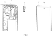
- FIG. 1 is an exploded view of an electronic device including a camera module in the conventional technology.
- an electronic device with a front-facing camera usually includes a housing 1', a camera module 2', and a screen 3'.
- the housing 1' and the screen 3' can be assembled together to form an accommodating cavity, and a silkscreen ring 31' is provided on the screen 3'.
- the camera module 2' is mounted in the accommodating cavity formed by the housing 1' and the screen 3', and a location of the silkscreen ring 31' is disposed corresponding to a location of a lens 21' of the camera module 2', so that external light can enter the camera module 2' through the silkscreen ring 31', and the camera module 2' processes the light to form an image.
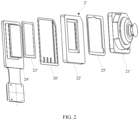
- FIG. 2 is a three-dimensional exploded view of a camera module in the conventional technology.
- the camera module 2' in the conventional technology includes the lens 21', a lens holder 22', a photosensitive chip 23', and a rigid-flexible board 24'.
- the lens 21' is adhered to the lens holder 22' by using a first adhesive layer 25'
- the photosensitive chip 23' is further disposed between the rigid-flexible board 24' and the lens holder 22'
- the lens holder 22' is adhered to the rigid-flexible board 24' by using a second adhesive layer 26', to form a finished product of the camera module 2'.
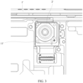
- FIG. 3 and FIG. 4 FIG.
- FIG. 3 is a schematic diagram of a mounting structure of a camera module in the conventional technology
- FIG. 4 is an exploded view obtained from another perspective of an electronic device including a camera module in the conventional technology.
- the camera module 2' is mounted in a limiting groove 11' of the housing 1', and the lens holder 22' of the camera module 2' is enabled to cooperate with the limiting groove 11' of the housing 1' in limiting to limit the lens 21' of the camera module 2'; and then the screen 3' is mounted in the housing 1', and the location of the silkscreen ring 31' on the screen 3' is enabled to be disposed corresponding to the location of the lens 21' of the camera pair module.
- a positioning path of the front-facing camera in the conventional technology includes: positioning of the silkscreen ring on the screen 3', assembly positioning between the screen 3' and the housing 1', positioning of the limiting groove 11', positioning between the lens holder 22' and the limiting groove 11', and positioning of the lens 21' and the lens holder 22'.
- a positioning deviation of each of the foregoing components or a positioning deviation between the components ultimately affects a positioning deviation between the lens 21' and the silkscreen ring 31'.
- FIG. 5 is a diagram of a dimension chain in a camera module mounting solution in the conventional technology.
- a' is a central location of the silkscreen ring 31'
- b' is a central location of the screen 3'
- c' is a central location of the housing 1'
- d' is a boundary location of the limiting groove 11'
- e' is a central location of the lens holder 22'
- f is a central location of the lens 21'.
- Positioning of the silkscreen ring on the screen 3' is positioning H1 between a center of the silkscreen ring and a center of the screen
- assembly positioning between the screen 3' and the housing 1' is positioning H2 between the center of the screen 3' and a center of the housing 1'
- positioning of the limiting groove 1 1' is positioning H3 between a boundary of the limiting groove and the center of the housing 1'
- positioning between the lens holder 22' and the limiting groove 11' is positioning H4 between the boundary of the limiting groove and a center of the lens holder 22'
- positioning between the lens 21' and the lens holder 22' is positioning H5 between the center of the lens holder 22' and a center of the lens 21'
- positioning between the lens 21' and the silkscreen ring 31' is positioning H6 between the center of the lens 21' and the center of the silkscreen ring 31'.
- a positioning deviation between the lens 21' and the silkscreen ring 31' is affected by at least deviations of the foregoing five types of positioning, resulting in an excessive long positioning eccentricity dimension chain of the lens 21', which affects assembly precision and a yield of the entire electronic device.
- FIG. 6 is a schematic diagram of a mounting structure of a camera module according to an embodiment of this application
- FIG. 7 is an exploded view of an electronic device including a camera module according to an embodiment of this application.
- the electronic device includes a housing 1, a camera module 2, a limiting bracket 3, and a screen 4.
- the screen 4 and the housing 1 can be assembled together to form an accommodating cavity, and a silkscreen ring 41 is provided on the screen 4.
- the camera module 2 is mounted in the accommodating cavity formed by the screen 4 and the housing 1.
- the limiting bracket 3 is sleeved on the camera module 2.
- the limiting bracket 3 can cooperate with the housing 1 in limiting to limit a lens of the camera module 2, and a location of the lens of the camera module 2 is precisely disposed corresponding to a location of the silkscreen ring 41, so that external light can enter the camera module 2 through the silkscreen ring 41, and the camera module 2 processes the light to form an image.
- one side of the housing 1 is provided with a limiting groove 11, the limiting bracket 3 is sleeved on the lens of the camera module 2, both the limiting bracket 3 and the camera module 2 are mounted in the housing 1, and the limiting bracket 3 is enabled to be located in the limiting groove 11.
- the lens of the camera module 2 is limited through cooperative limiting of the limiting bracket 3 and the limiting groove 11.
- the screen 4 is disposed on a side that is of the housing 1 and on which the camera module 2 is disposed, and a location of the silkscreen ring 41 is disposed corresponding to a location of the lens of the camera module 2.
- the limiting bracket 3 is disposed, and the lens of the camera module 2 is positioned through cooperative limiting of the limiting bracket 3 and the limiting groove 11 of the housing 1, so that a positioning eccentricity dimension chain of the lens of the camera module 2 is reduced, and the lens of the camera module 2 is precisely aligned with the silkscreen ring 41 on the screen 4, thereby increasing assembly precision and a yield of the entire electronic device.
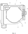
- FIG. 8 is a diagram of a structure of a limiting bracket according to an embodiment of this application
- FIG. 9 is a diagram of assembly of a camera module and a limiting bracket according to an embodiment of this application.
- the limiting bracket 3 includes a limiting bracket body 31, a first limiting adjustment member 32, and a second limiting adjustment member 33.
- the limiting bracket body 31 has a limiting hole 311.
- a shape of the limiting hole 311 is disposed corresponding to an outer peripheral shape of the lens of the camera module 2, to limit the lens of the camera module 2 through the limiting hole 311.
- An outer peripheral sidewall shape of the limiting bracket body 31 is disposed corresponding to a shape of the limiting groove 11, to limit the limiting bracket 3 through the limiting groove 11.
- the first limiting adjustment member 32 is disposed on a side of an inner peripheral sidewall of the limiting hole 311, so that appropriate extrusion force is applied to the lens of the camera module 2 by using the first limiting adjustment member 32, to stably limit the lens of the camera module 2 in the limiting hole 311, thereby preventing the lens of the camera module 2 from being displaced in the limiting hole 311.
- the second limiting adjustment member 33 is disposed on a side of an outer peripheral sidewall of the limiting bracket body 31, so that appropriate extrusion force is applied to the limiting bracket 3 through mutual interaction between the second limiting adjustment member 33 and an inner wall of the limiting groove 11, to stably limit the limiting bracket 3 in the limiting groove 11, thereby preventing the limiting bracket 3 from being displaced in the limiting groove 11.
- the limiting bracket body 31 is made of a hard material, and the hard material may be, for example, an acrylonitrile-butadiene-styrene (Acrylonitrile-Butadiene-styrene, ABS for short) copolymer, polyoxymethylene (English full name: Polyoxymethylene, POM for short), polystyrene (English full name: Polystyrene, PS for short), polymethylmethacrylate (English full name: polymethylmethacrylate, PMMA for short), polycarbonate (English full name: Polycarbonate, PC for short), polyethylene terephthalate (English full name: Polyethylene terephthalate, PET for short), polybutylene terephthalate (English full name: polybutylene terephthalate, PBT for short), or polyphenylene oxide (English full name: Polyphenylene Oxide, PPO for short).
- an acrylonitrile-butadiene-styrene Acrylonitrile-Butad
- Both the first limiting adjustment member 32 and the second limiting adjustment member 33 are made of a soft material, and the soft material may be, for example, a thermoplastic polyurethane (English full name: Thermoplastic Urethane, TPU for short) elastomer, a thermoplastic elastomer (English name: Thermoplastic elastomer, TPE for short), a thermo-plastic-rubber material (English full name: Thermo-Plastic-Rubber material, TPR for short), silicone rubber, or rubber.
- a thermoplastic polyurethane English full name: Thermoplastic Urethane, TPU for short
- a thermoplastic elastomer English name: Thermoplastic elastomer, TPE for short
- thermo-plastic-rubber material English full name: Thermo-Plastic-Rubber material, TPR for short
- silicone rubber or rubber.
- the first limiting adjustment member 32 is disposed on the inner peripheral sidewall of the limiting hole 311 of the limiting bracket body 31, and the second limiting adjustment member 33 is disposed on the outer peripheral sidewall of the limiting bracket body 31, to eliminate an assembly gap between the lens of the camera module 2 and the limiting bracket 3 and an assembly gap between the limiting bracket 3 and the housing 1 through an interference fit between the first limiting adjustment member 32 and the lens of the camera module 2 and an interference fit between the second limiting adjustment member 33 and the limiting groove 11 of the housing 1, thereby increasing positioning precision of the lens of the camera module 2.
- a plurality of first limiting adjustment members 32 are disposed, and the plurality of first limiting adjustment members 32 are disposed at intervals on the side of the inner peripheral sidewall of the limiting hole 311. Further, the plurality of first limiting adjustment members 32 are disposed in the limiting bracket body 31 through injection molding.
- a plurality of second limiting adjustment members 33 are disposed, and the plurality of second limiting adjustment members 33 are disposed at intervals on the side of the outer peripheral sidewall of the limiting bracket body 31. Further, the plurality of second limiting adjustment members 33 are disposed in the limiting bracket body 31 through injection molding.
- first limiting adjustment members 32 may alternatively be disposed on an entire half of the inner peripheral sidewall of the limiting hole 311, and the second limiting adjustment members 33 may alternatively be disposed on an entire half of the outer peripheral sidewall of the limiting bracket body 31.
- the first limiting adjustment members 32 are disposed only on the side of the inner peripheral sidewall of the limiting hole 311, so that in an X direction or a Y direction, the lens of the camera module 2 is subjected to extrusion force only in a single direction.
- the lens of the camera module 2 is subjected to force only in a +X direction
- the lens of the camera module 2 is subjected to force only in a +Y direction
- the lens of the camera module 2 is subjected to force only in a +Y direction
- the camera module 2 is subjected to force only in a -Y direction.
- the lens of the camera module 2 is stably fastened in the limiting bracket 3, so that the assembly gap between the lens of the camera module 2 and the limiting bracket 3 is reduced, thereby increasing positioning precision of the lens of the camera module 2.
- the second limiting adjustment members 33 are disposed only on the side of the outer peripheral sidewall of the limiting bracket body 31, so that in the X direction or the Y direction, the limiting bracket body 31 is subjected to force only in a single direction.
- the limiting bracket body 31 is subjected to force only in the +X direction, and in the Y direction, the limiting bracket body 31 is subjected to force only in the +Y direction; or in the X direction, the limiting bracket body 31 is subjected to force only in the -X direction, and in the Y direction, the limiting bracket body 31 is subjected to force only in the -Y direction.
- the limiting bracket 3 is stably fastened in the limiting groove 11 of the housing 1, so that the assembly gap between the limiting bracket 3 and the limiting groove 11 of the housing 1 is reduced, thereby further increasing positioning precision of the lens of the camera module 2.
- a positioning path of a front-facing camera in this application includes: positioning of the silkscreen ring on the screen 4, assembly positioning between the screen 4 and the housing 1, positioning of the limiting groove 11, and positioning between the limiting bracket 3 and the limiting groove 11.
- a positioning deviation of each of the foregoing components or a positioning deviation between the components ultimately affects a positioning deviation between the lens of the camera module 2 and the silkscreen ring 41 on the screen 4.
- FIG. 10 is a diagram of a dimension chain in a camera module mounting solution according to an embodiment of this application. In FIG.
- a is a central location of the silkscreen ring 41
- b is a central location of the screen 4
- c is a central location of the housing 1
- d is a boundary location of the limiting groove 11
- e is a central location of the lens of the camera module 2.
- Positioning of the silkscreen ring on the screen 4 is positioning W1 between a center of the silkscreen ring 41 and a center of the screen 4, assembly positioning between the screen 4 and the housing 1 is positioning W2 between the center of the screen 4 and a center of the housing 1, positioning of the limiting groove 11 is positioning W3 between a boundary of the limiting groove and the center of the housing 1, positioning between the limiting bracket 3 and the limiting groove 11 is positioning W4 between the boundary of the limiting groove and a center of the limiting bracket 3, and positioning between the lens of the camera module 2 and the silkscreen ring 41 is positioning W5 between a center of the lens and the center of the silkscreen ring 41.
- a positioning deviation between the lens of the camera module 2 and the silkscreen ring 41 in this application is affected by a maximum of four positioning deviations.
- a positioning deviation between the lens of the camera module 2 and a lens holder and a positioning deviation between the lens holder and the limiting groove 11 are reduced, so that a positioning eccentricity dimension chain of the lens of the camera module 2 is reduced, thereby increasing assembly precision and a yield of the entire electronic device.
- the housing of the electronic device is directly used to position the lens holder of the camera module, and as a result, the positioning eccentricity dimension chain of the lens of the photographing module is long, and there is a high requirement on assembly precision of the camera module 2.
- the housing 1 is used to position the limiting bracket 3, so that the positioning eccentricity dimension chain of the lens of the camera module 2 is reduced, and a requirement on assembly precision of the camera module 2 is reduced.
- the foregoing electronic device may be a tablet, a mobile phone, or the like that has a front camera.
- this application further discloses a manufacturing method for an electronic device.
- the manufacturing method is used to manufacture the electronic device in any one of the foregoing embodiments. Specifically, the manufacturing method includes the following steps.
- a limiting hole is provided on a limiting bracket body, where a shape of the limiting hole is disposed corresponding to an outer peripheral shape of a lens of a camera module.
- a first limiting adjustment member is disposed on a side of an inner peripheral sidewall of the limiting hole of the limiting bracket body, and a second limiting adjustment member is disposed on a side of an outer peripheral sidewall of the limiting bracket body, to form the limiting bracket through assembly.
- S13 Separately mount the limiting bracket and the camera module in a housing, and enable the limiting bracket to cooperate with a limiting groove of the housing in limiting to limit the lens.
- the housing is provided with the limiting groove, where a shape of the limiting groove is disposed corresponding to an outer peripheral shape of the limiting bracket; the limiting bracket is further sleeved on the lens of the camera module; and the limiting bracket and the camera module are separately mounted in the housing, and the limiting bracket is enabled to cooperate with the limiting groove in limiting to position the lens of the camera module.
- S14 Mount a screen on a side that is of the housing and on which the camera module is disposed, and a location of a silkscreen ring on the screen is enabled to be disposed corresponding to a location of the lens.
- the limiting bracket 3 is disposed, and the lens of the camera module 2 is positioned through cooperative limiting of the limiting bracket 3 and limiting groove 11 of the housing 1, so that a positioning eccentricity dimension chain of the lens of the camera module 2 is reduced, and the lens of the camera module 2 is precisely aligned with the silkscreen ring 41 on the screen 4, thereby increasing assembly precision and a yield of the entire electronic device.
Landscapes
- Engineering & Computer Science (AREA)
- Signal Processing (AREA)
- Multimedia (AREA)
- Lens Barrels (AREA)
- Studio Devices (AREA)
Abstract
Description
- This application claims priority to
Chinese Patent Application No. 202210945385.3, filed with the China National Intellectual Property Administration on August 8, 2022 - This application relates to the field of electronic technologies, and specifically, to an electronic device and a manufacturing method for an electronic device.
- An existing electronic device that includes a front-facing camera usually includes a housing, the front-facing camera, and a screen. A process of mounting the front-facing camera is as follows: The camera and each component are assembled together through adhesion to form a camera module; the camera module is further mounted in the housing, and a lens holder of the camera module is enabled to be located in a limiting groove of the housing, so that a lens of the camera module is limited through cooperative limiting of the limiting groove of the housing and the lens holder; and then the screen is mounted on a side that is of the housing and on which the camera module is disposed, and a location of a silkscreen ring on the screen is enabled to be disposed corresponding to a location of the lens.
- The front-facing camera assembly structure of the electronic device includes a plurality of size errors, which affects assembly precision and a yield of the entire electronic device.
- To overcome the foregoing problems existing in the conventional technology, a main purpose of this application is to provide an electronic device that can increase assembly precision and a yield of the entire electronic device.
- To achieve the foregoing objective, the following technical solutions are specifically used in this application.
- This application provides an electronic device. The electronic device includes:
- a housing, where one side of the housing is provided with a limiting groove;
- a camera module, where the camera module is mounted in the housing, and the camera module includes a lens;
- a limiting bracket, where the limiting bracket is sleeved on the lens, and the limiting bracket is disposed in the limiting groove, to limit the lens through cooperative limiting of the limiting bracket and the limiting groove; and
- a screen, where the screen is disposed on a side that is of the housing and on which the camera module is disposed, a silkscreen ring is provided on the screen, and a location of the silkscreen ring is disposed corresponding to a location of the lens. In this embodiment, the limiting bracket is disposed, and the lens can be limited through cooperative limiting of the limiting bracket and the limiting groove of the housing, so that a positioning eccentricity dimension chain of the lens is reduced, and the lens is precisely aligned with the silkscreen ring on the screen, thereby increasing assembly precision and a yield of the entire electronic device.
- In some embodiments, the limiting bracket includes a limiting bracket body, the limiting bracket body has a limiting hole, a shape of the limiting hole is disposed corresponding to a shape of the lens, and an outer peripheral shape of the limiting bracket body is disposed corresponding to a shape of the limiting groove. In this embodiment, the shape of the limiting hole is disposed corresponding to the shape of the lens, so that the limiting bracket can better cooperate with the lens in limiting, and the outer peripheral shape of the limiting bracket is disposed corresponding to the shape of the limiting groove, so that the limiting bracket can better cooperate with the limiting groove in limiting, thereby increasing positioning precision of the lens.
- In some embodiments, the limiting bracket further includes a first limiting adjustment member, the first limiting adjustment member is disposed on a side of an inner peripheral sidewall of the limiting hole, the limiting bracket body is made of a hard material, and the first limiting adjustment member is made of a soft material. In this embodiment, the first limiting adjustment member is disposed on the side of the inner peripheral sidewall of the limiting hole, to eliminate an assembly gap between the lens and the limiting bracket, thereby increasing positioning precision of the lens.
- In some embodiments, a plurality of the first limiting adjustment members are disposed, and the plurality of first limiting adjustment members are disposed at intervals on the side of the inner peripheral sidewall of the limiting hole. In this embodiment, the plurality of first limiting adjustment members are disposed at intervals on the inner peripheral sidewall of the limiting hole, instead of disposing the first limiting adjustment member on an entire half of the inner peripheral sidewall of the limiting hole, thereby reducing use of materials of the first limiting adjustment member and reducing costs.
- In some embodiments, the limiting bracket further includes a second limiting adjustment member, the second limiting adjustment member is disposed on a side of an outer peripheral sidewall of the limiting bracket body, the limiting bracket body is made of a hard material, and the second limiting adjustment member is made of a soft material. In this embodiment, the second limiting adjustment member is disposed on the side of the outer peripheral sidewall of the limiting bracket body, to eliminate an assembly gap between the limiting bracket and the housing, thereby increasing positioning precision of the lens.
- In some embodiments, a plurality of the second limiting adjustment members are disposed, and the plurality of second limiting adjustment members are disposed at intervals on the side of the outer peripheral sidewall of the limiting bracket body. In this embodiment, the plurality of second limiting adjustment members are disposed at intervals on the outer peripheral sidewall of the limiting bracket body, instead of disposing the second limiting adjustment member on an entire half of the outer peripheral sidewall of the limiting bracket body, thereby reducing use of materials of the second limiting adjustment member and reducing costs.
- In some embodiments, the camera module further includes a lens holder, a photosensitive chip, and a rigid-flexible board, and the lens, the lens holder, the photosensitive chip, and the rigid-flexible board are connected in sequence to form the camera module.
- In some embodiments, the lens is connected to the lens holder through adhesion, and the lens holder is connected to the rigid-flexible board through adhesion.
- Correspondingly, this application further provides a manufacturing method for an electronic device. The electronic device includes a housing, a limiting bracket, a camera module, and a screen. The manufacturing method includes:
- sleeving the limiting bracket on a lens of the camera module;
- separately mounting the limiting bracket and the camera module in the housing, and enabling the limiting bracket to cooperate with a limiting groove of the housing in limiting to limit the lens; and
- mounting the screen on a side that is of the housing and on which the camera module is disposed, and enabling a location of a silkscreen ring on the screen to be disposed corresponding to a location of the lens.
- In this embodiment, the limiting bracket is sleeved on the lens of the camera module, then the limiting bracket and the camera module are separately mounted in the housing, and the limiting bracket is enabled to cooperate with the limiting groove of the housing in limiting to limit the lens, so that a positioning eccentricity dimension chain of the lens is reduced, and the lens is precisely aligned with the silkscreen ring on the screen, thereby increasing assembly precision and a yield of the entire electronic device.
- In some embodiments, before the step of sleeving the limiting bracket on a lens of the camera module, the method further includes:
assembling the limiting bracket, where the assembling the limiting bracket specifically includes: - disposing a first limiting adjustment member on a side of an inner peripheral sidewall of a limiting hole of a limiting bracket body; and
- disposing a second limiting adjustment member on a side of an outer peripheral sidewall of the limiting bracket body, to form the limiting bracket.
- In this embodiment, the first limiting adjustment member is disposed on the side of the inner peripheral sidewall of the limiting hole, and the second limiting adjustment member is disposed on the side of the outer peripheral sidewall of the limiting bracket body, to eliminate an assembly gap between the lens and the limiting bracket and an assembly gap between the limiting bracket and the housing, thereby increasing positioning precision of the lens.
- Compared with the conventional technology, the electronic device in this application includes a housing, a camera module, a limiting bracket, and a screen. One side of the housing is provided with a limiting groove, the camera module is mounted in the housing, and the camera module includes a lens. The limiting bracket is sleeved on the lens, and the limiting bracket is disposed in the limiting groove, to limit the lens through cooperative limiting of the limiting bracket and the limiting groove. The screen is disposed on a side that is of the housing and on which the camera module is disposed, and a silkscreen ring is provided on the screen, where a location of the silkscreen ring is disposed corresponding to a location of the lens. In this application, the limiting bracket is disposed, and the lens is limited through cooperative limiting of the limiting bracket and the limiting groove of the housing, so that a positioning eccentricity dimension chain of the lens is reduced, thereby increasing assembly precision and a yield of the entire electronic device.
-
-
FIG. 1 is an exploded view of an electronic device including a camera module in the conventional technology; -
FIG. 2 is a three-dimensional exploded view of a camera module in the conventional technology; -
FIG. 3 is a schematic diagram of a mounting structure of a camera module in the conventional technology; -
FIG. 4 is an exploded view obtained from another perspective of an electronic device including a camera module in the conventional technology; -
FIG. 5 is a diagram of a dimension chain in a camera module mounting solution in the conventional technology; -
FIG. 6 is a schematic diagram of a mounting structure of a camera module according to an embodiment of this application; -
FIG. 7 is an exploded view of an electronic device including a camera module according to an embodiment of this application; -
FIG. 8 is a diagram of a structure of a limiting bracket according to an embodiment of this application; -
FIG. 9 is a diagram of assembly of a camera module and a limiting bracket according to an embodiment of this application; and -
FIG. 10 is a diagram of a dimension chain in a camera module mounting solution according to an embodiment of this application. - 1. housing; 11. limiting groove; 2. camera module; 3. limiting bracket; 31. limiting bracket body; 311. limiting hole; 32. first limiting adjustment member; 33. second limiting adjustment member; 4. screen; 41. silkscreen ring; 1'. housing; 11'. limiting groove; 2'. camera module; 21'. lens; 22'. lens holder; 23'. photosensitive chip; 24'. rigid-flexible board; 25'. first adhesive layer; 26'. second adhesive layer; 3'. screen; and 31'. silkscreen ring.
- To make the objectives, technical solutions, and advantages of this application clearer, the following further describes this application in detail with reference to the accompanying drawings and embodiments. It should be understood that specific embodiments described herein are merely used to explain this application, but are not intended to limit this application.
- In the descriptions of this application, unless otherwise specified and defined explicitly, the terms "first" and "second" are merely intended for the purpose of description, and shall not be understood as an indication or implication of relative importance; unless otherwise specified or stated, the term "a plurality of" means two or more; and the terms such as "connection" and "fastening" should be understood in a broad sense. For example, the "connection" may be a fixed connection, a detachable connection, an integrated connection, or an electrical connection; or may be a direct connection or an indirect connection through an intermediate medium. A person of ordinary skill in the art may understand specific meanings of the foregoing terms in the present invention based on a specific situation.
- In the descriptions of the specification, it should be understood that the directional words such as "up" and "down" described in the embodiments of this application are described from perspectives shown in the accompanying drawings, and shall not be understood as a limitation on the embodiments of this application. In addition, in the context, it should be further understood that when it is mentioned that an element is connected to another element, the element can be directly connected to the another element, or may be indirectly connected to the another element through an intermediate element.
- Referring to
FIG. 1, FIG. 1 is an exploded view of an electronic device including a camera module in the conventional technology. In the conventional technology, an electronic device with a front-facing camera usually includes a housing 1', a camera module 2', and a screen 3'. The housing 1' and the screen 3' can be assembled together to form an accommodating cavity, and a silkscreen ring 31' is provided on the screen 3'. The camera module 2' is mounted in the accommodating cavity formed by the housing 1' and the screen 3', and a location of the silkscreen ring 31' is disposed corresponding to a location of a lens 21' of the camera module 2', so that external light can enter the camera module 2' through the silkscreen ring 31', and the camera module 2' processes the light to form an image. - Referring to
FIG. 2, FIG. 2 is a three-dimensional exploded view of a camera module in the conventional technology. The camera module 2' in the conventional technology includes the lens 21', a lens holder 22', a photosensitive chip 23', and a rigid-flexible board 24'. During assembly of the camera module 2', the lens 21' is adhered to the lens holder 22' by using a first adhesive layer 25', the photosensitive chip 23' is further disposed between the rigid-flexible board 24' and the lens holder 22', and then the lens holder 22' is adhered to the rigid-flexible board 24' by using a second adhesive layer 26', to form a finished product of the camera module 2'. Referring toFIG. 3 andFIG. 4 ,FIG. 3 is a schematic diagram of a mounting structure of a camera module in the conventional technology, andFIG. 4 is an exploded view obtained from another perspective of an electronic device including a camera module in the conventional technology. During mounting of the camera module 2', the camera module 2' is mounted in a limiting groove 11' of the housing 1', and the lens holder 22' of the camera module 2' is enabled to cooperate with the limiting groove 11' of the housing 1' in limiting to limit the lens 21' of the camera module 2'; and then the screen 3' is mounted in the housing 1', and the location of the silkscreen ring 31' on the screen 3' is enabled to be disposed corresponding to the location of the lens 21' of the camera pair module. Therefore, a positioning path of the front-facing camera in the conventional technology includes: positioning of the silkscreen ring on the screen 3', assembly positioning between the screen 3' and the housing 1', positioning of the limiting groove 11', positioning between the lens holder 22' and the limiting groove 11', and positioning of the lens 21' and the lens holder 22'. A positioning deviation of each of the foregoing components or a positioning deviation between the components ultimately affects a positioning deviation between the lens 21' and the silkscreen ring 31'. Specifically, referring toFIG. 5, FIG. 5 is a diagram of a dimension chain in a camera module mounting solution in the conventional technology. InFIG. 5 , a' is a central location of the silkscreen ring 31', b' is a central location of the screen 3', c' is a central location of the housing 1', d' is a boundary location of the limiting groove 11', e' is a central location of the lens holder 22', and f is a central location of the lens 21'. Positioning of the silkscreen ring on the screen 3' is positioning H1 between a center of the silkscreen ring and a center of the screen, assembly positioning between the screen 3' and the housing 1' is positioning H2 between the center of the screen 3' and a center of the housing 1', positioning of the limitinggroove 1 1' is positioning H3 between a boundary of the limiting groove and the center of the housing 1', positioning between the lens holder 22' and the limiting groove 11' is positioning H4 between the boundary of the limiting groove and a center of the lens holder 22', positioning between the lens 21' and the lens holder 22' is positioning H5 between the center of the lens holder 22' and a center of the lens 21', and positioning between the lens 21' and the silkscreen ring 31' is positioning H6 between the center of the lens 21' and the center of the silkscreen ring 31'. It may be learned that in the conventional technology, a positioning deviation between the lens 21' and the silkscreen ring 31' is affected by at least deviations of the foregoing five types of positioning, resulting in an excessive long positioning eccentricity dimension chain of the lens 21', which affects assembly precision and a yield of the entire electronic device. - Referring to both
FIG. 6 andFIG. 7 ,FIG. 6 is a schematic diagram of a mounting structure of a camera module according to an embodiment of this application, andFIG. 7 is an exploded view of an electronic device including a camera module according to an embodiment of this application. The electronic device includes ahousing 1, acamera module 2, a limitingbracket 3, and ascreen 4. Thescreen 4 and thehousing 1 can be assembled together to form an accommodating cavity, and asilkscreen ring 41 is provided on thescreen 4. Thecamera module 2 is mounted in the accommodating cavity formed by thescreen 4 and thehousing 1. The limitingbracket 3 is sleeved on thecamera module 2. In addition, the limitingbracket 3 can cooperate with thehousing 1 in limiting to limit a lens of thecamera module 2, and a location of the lens of thecamera module 2 is precisely disposed corresponding to a location of thesilkscreen ring 41, so that external light can enter thecamera module 2 through thesilkscreen ring 41, and thecamera module 2 processes the light to form an image. - Specifically, one side of the
housing 1 is provided with a limitinggroove 11, the limitingbracket 3 is sleeved on the lens of thecamera module 2, both the limitingbracket 3 and thecamera module 2 are mounted in thehousing 1, and the limitingbracket 3 is enabled to be located in the limitinggroove 11. The lens of thecamera module 2 is limited through cooperative limiting of the limitingbracket 3 and the limitinggroove 11. Thescreen 4 is disposed on a side that is of thehousing 1 and on which thecamera module 2 is disposed, and a location of thesilkscreen ring 41 is disposed corresponding to a location of the lens of thecamera module 2. - In this embodiment, the limiting
bracket 3 is disposed, and the lens of thecamera module 2 is positioned through cooperative limiting of the limitingbracket 3 and the limitinggroove 11 of thehousing 1, so that a positioning eccentricity dimension chain of the lens of thecamera module 2 is reduced, and the lens of thecamera module 2 is precisely aligned with thesilkscreen ring 41 on thescreen 4, thereby increasing assembly precision and a yield of the entire electronic device. - Referring to
FIG. 8 andFIG. 9 ,FIG. 8 is a diagram of a structure of a limiting bracket according to an embodiment of this application, andFIG. 9 is a diagram of assembly of a camera module and a limiting bracket according to an embodiment of this application. The limitingbracket 3 includes a limitingbracket body 31, a first limitingadjustment member 32, and a second limitingadjustment member 33. The limitingbracket body 31 has a limitinghole 311. A shape of the limitinghole 311 is disposed corresponding to an outer peripheral shape of the lens of thecamera module 2, to limit the lens of thecamera module 2 through the limitinghole 311. An outer peripheral sidewall shape of the limitingbracket body 31 is disposed corresponding to a shape of the limitinggroove 11, to limit the limitingbracket 3 through the limitinggroove 11. The first limitingadjustment member 32 is disposed on a side of an inner peripheral sidewall of the limitinghole 311, so that appropriate extrusion force is applied to the lens of thecamera module 2 by using the first limitingadjustment member 32, to stably limit the lens of thecamera module 2 in the limitinghole 311, thereby preventing the lens of thecamera module 2 from being displaced in the limitinghole 311. The second limitingadjustment member 33 is disposed on a side of an outer peripheral sidewall of the limitingbracket body 31, so that appropriate extrusion force is applied to the limitingbracket 3 through mutual interaction between the second limitingadjustment member 33 and an inner wall of the limitinggroove 11, to stably limit the limitingbracket 3 in the limitinggroove 11, thereby preventing the limitingbracket 3 from being displaced in the limitinggroove 11. - The limiting
bracket body 31 is made of a hard material, and the hard material may be, for example, an acrylonitrile-butadiene-styrene (Acrylonitrile-Butadiene-styrene, ABS for short) copolymer, polyoxymethylene (English full name: Polyoxymethylene, POM for short), polystyrene (English full name: Polystyrene, PS for short), polymethylmethacrylate (English full name: polymethylmethacrylate, PMMA for short), polycarbonate (English full name: Polycarbonate, PC for short), polyethylene terephthalate (English full name: Polyethylene terephthalate, PET for short), polybutylene terephthalate (English full name: polybutylene terephthalate, PBT for short), or polyphenylene oxide (English full name: Polyphenylene Oxide, PPO for short). Both the first limitingadjustment member 32 and the second limitingadjustment member 33 are made of a soft material, and the soft material may be, for example, a thermoplastic polyurethane (English full name: Thermoplastic Urethane, TPU for short) elastomer, a thermoplastic elastomer (English name: Thermoplastic elastomer, TPE for short), a thermo-plastic-rubber material (English full name: Thermo-Plastic-Rubber material, TPR for short), silicone rubber, or rubber. - In this embodiment, the first limiting
adjustment member 32 is disposed on the inner peripheral sidewall of the limitinghole 311 of the limitingbracket body 31, and the second limitingadjustment member 33 is disposed on the outer peripheral sidewall of the limitingbracket body 31, to eliminate an assembly gap between the lens of thecamera module 2 and the limitingbracket 3 and an assembly gap between the limitingbracket 3 and thehousing 1 through an interference fit between the first limitingadjustment member 32 and the lens of thecamera module 2 and an interference fit between the second limitingadjustment member 33 and the limitinggroove 11 of thehousing 1, thereby increasing positioning precision of the lens of thecamera module 2. - In this embodiment, a plurality of first limiting
adjustment members 32 are disposed, and the plurality of first limitingadjustment members 32 are disposed at intervals on the side of the inner peripheral sidewall of the limitinghole 311. Further, the plurality of first limitingadjustment members 32 are disposed in the limitingbracket body 31 through injection molding. A plurality of second limitingadjustment members 33 are disposed, and the plurality of second limitingadjustment members 33 are disposed at intervals on the side of the outer peripheral sidewall of the limitingbracket body 31. Further, the plurality of second limitingadjustment members 33 are disposed in the limitingbracket body 31 through injection molding. It may be understood that, in another embodiment, the first limitingadjustment members 32 may alternatively be disposed on an entire half of the inner peripheral sidewall of the limitinghole 311, and the second limitingadjustment members 33 may alternatively be disposed on an entire half of the outer peripheral sidewall of the limitingbracket body 31. - In this embodiment, the first limiting
adjustment members 32 are disposed only on the side of the inner peripheral sidewall of the limitinghole 311, so that in an X direction or a Y direction, the lens of thecamera module 2 is subjected to extrusion force only in a single direction. For example, in the X direction, the lens of thecamera module 2 is subjected to force only in a +X direction, and in the Y direction, the lens of thecamera module 2 is subjected to force only in a +Y direction; or in the X direction, the lens of thecamera module 2 is subjected to force only in a -X direction, and in the Y direction, thecamera module 2 is subjected to force only in a -Y direction. In this way, the lens of thecamera module 2 is stably fastened in the limitingbracket 3, so that the assembly gap between the lens of thecamera module 2 and the limitingbracket 3 is reduced, thereby increasing positioning precision of the lens of thecamera module 2. In addition, in this embodiment, the second limitingadjustment members 33 are disposed only on the side of the outer peripheral sidewall of the limitingbracket body 31, so that in the X direction or the Y direction, the limitingbracket body 31 is subjected to force only in a single direction. For example, in the X direction, the limitingbracket body 31 is subjected to force only in the +X direction, and in the Y direction, the limitingbracket body 31 is subjected to force only in the +Y direction; or in the X direction, the limitingbracket body 31 is subjected to force only in the -X direction, and in the Y direction, the limitingbracket body 31 is subjected to force only in the -Y direction. In this way, the limitingbracket 3 is stably fastened in the limitinggroove 11 of thehousing 1, so that the assembly gap between the limitingbracket 3 and the limitinggroove 11 of thehousing 1 is reduced, thereby further increasing positioning precision of the lens of thecamera module 2. - A positioning path of a front-facing camera in this application includes: positioning of the silkscreen ring on the
screen 4, assembly positioning between thescreen 4 and thehousing 1, positioning of the limitinggroove 11, and positioning between the limitingbracket 3 and the limitinggroove 11. A positioning deviation of each of the foregoing components or a positioning deviation between the components ultimately affects a positioning deviation between the lens of thecamera module 2 and thesilkscreen ring 41 on thescreen 4. Specifically, referring toFIG. 10, FIG. 10 is a diagram of a dimension chain in a camera module mounting solution according to an embodiment of this application. InFIG. 10 , a is a central location of thesilkscreen ring 41, b is a central location of thescreen 4, c is a central location of thehousing 1, d is a boundary location of the limitinggroove 11, and e is a central location of the lens of thecamera module 2. Positioning of the silkscreen ring on thescreen 4 is positioning W1 between a center of thesilkscreen ring 41 and a center of thescreen 4, assembly positioning between thescreen 4 and thehousing 1 is positioning W2 between the center of thescreen 4 and a center of thehousing 1, positioning of the limitinggroove 11 is positioning W3 between a boundary of the limiting groove and the center of thehousing 1, positioning between the limitingbracket 3 and the limitinggroove 11 is positioning W4 between the boundary of the limiting groove and a center of the limitingbracket 3, and positioning between the lens of thecamera module 2 and thesilkscreen ring 41 is positioning W5 between a center of the lens and the center of thesilkscreen ring 41. It may be learned that, a positioning deviation between the lens of thecamera module 2 and thesilkscreen ring 41 in this application is affected by a maximum of four positioning deviations. Compared with the conventional technology, a positioning deviation between the lens of thecamera module 2 and a lens holder and a positioning deviation between the lens holder and the limitinggroove 11 are reduced, so that a positioning eccentricity dimension chain of the lens of thecamera module 2 is reduced, thereby increasing assembly precision and a yield of the entire electronic device. - In the conventional technology, the housing of the electronic device is directly used to position the lens holder of the camera module, and as a result, the positioning eccentricity dimension chain of the lens of the photographing module is long, and there is a high requirement on assembly precision of the
camera module 2. In this application, thehousing 1 is used to position the limitingbracket 3, so that the positioning eccentricity dimension chain of the lens of thecamera module 2 is reduced, and a requirement on assembly precision of thecamera module 2 is reduced. - The foregoing electronic device may be a tablet, a mobile phone, or the like that has a front camera.
- Correspondingly, this application further discloses a manufacturing method for an electronic device. The manufacturing method is used to manufacture the electronic device in any one of the foregoing embodiments. Specifically, the manufacturing method includes the following steps.
- S11: Assemble a limiting bracket.
- Specifically, a limiting hole is provided on a limiting bracket body, where a shape of the limiting hole is disposed corresponding to an outer peripheral shape of a lens of a camera module. A first limiting adjustment member is disposed on a side of an inner peripheral sidewall of the limiting hole of the limiting bracket body, and a second limiting adjustment member is disposed on a side of an outer peripheral sidewall of the limiting bracket body, to form the limiting bracket through assembly.
- S12: Sleeve the limiting bracket on the lens of the camera module.
- S13: Separately mount the limiting bracket and the camera module in a housing, and enable the limiting bracket to cooperate with a limiting groove of the housing in limiting to limit the lens.
- Specifically, the housing is provided with the limiting groove, where a shape of the limiting groove is disposed corresponding to an outer peripheral shape of the limiting bracket; the limiting bracket is further sleeved on the lens of the camera module; and the limiting bracket and the camera module are separately mounted in the housing, and the limiting bracket is enabled to cooperate with the limiting groove in limiting to position the lens of the camera module.
- S14: Mount a screen on a side that is of the housing and on which the camera module is disposed, and a location of a silkscreen ring on the screen is enabled to be disposed corresponding to a location of the lens.
- In this application, the limiting
bracket 3 is disposed, and the lens of thecamera module 2 is positioned through cooperative limiting of the limitingbracket 3 and limitinggroove 11 of thehousing 1, so that a positioning eccentricity dimension chain of the lens of thecamera module 2 is reduced, and the lens of thecamera module 2 is precisely aligned with thesilkscreen ring 41 on thescreen 4, thereby increasing assembly precision and a yield of the entire electronic device. - The foregoing descriptions are merely preferred specific implementations of this application, but are not intended to limit the protection scope of this application. Any modification or replacement readily figured out by a person skilled in the art within the technical scope disclosed in this application shall fall within the protection scope of this application. Therefore, the protection scope of this application shall be subject to the protection scope of the claims.
Claims (10)
- An electronic device, comprising:a housing, wherein one side of the housing is provided with a limiting groove;a camera module, wherein the camera module is mounted in the housing, and the camera module comprises a lens;a limiting bracket, wherein the limiting bracket is sleeved on the lens, and the limiting bracket is disposed in the limiting groove, to limit the lens through cooperative limiting of the limiting bracket and the limiting groove; anda screen, wherein the screen is disposed on a side that is of the housing and on which the camera module is disposed, a silkscreen ring is provided on the screen, and a location of the silkscreen ring is disposed corresponding to a location of the lens.
- The electronic device according to claim 1, wherein the limiting bracket comprises a limiting bracket body, the limiting bracket body has a limiting hole, a shape of the limiting hole is disposed corresponding to a shape of the lens, and an outer peripheral shape of the limiting bracket body is disposed corresponding to a shape of the limiting groove.
- The electronic device according to claim 2, wherein the limiting bracket further comprises a first limiting adjustment member, the first limiting adjustment member is disposed on a side of an inner peripheral sidewall of the limiting hole, the limiting bracket body is made of a hard material, and the first limiting adjustment member is made of a soft material.
- The electronic device according to claim 3, wherein a plurality of the first limiting adjustment members are disposed, and the plurality of first limiting adjustment members are disposed at intervals on the side of the inner peripheral sidewall of the limiting hole.
- The electronic device according to claim 2, wherein the limiting bracket further comprises a second limiting adjustment member, the second limiting adjustment member is disposed on a side of an outer peripheral sidewall of the limiting bracket body, the limiting bracket body is made of a hard material, and the second limiting adjustment member is made of a soft material.
- The electronic device according to claim 5, wherein a plurality of the second limiting adjustment members are disposed, and the plurality of second limiting adjustment members are disposed at intervals on the side of the outer peripheral sidewall of the limiting bracket body.
- The electronic device according to any one of claims 1~6, wherein the camera module further comprises a lens holder, a photosensitive chip, and a rigid-flexible board, and the lens, the lens holder, the photosensitive chip, and the rigid-flexible board are connected in sequence to form the camera module.
- The electronic device according to claim 7, wherein the lens is connected to the lens holder through adhesion, and the lens holder is connected to the rigid-flexible board through adhesion.
- A manufacturing method for an electronic device, wherein the electronic device comprises a housing, a limiting bracket, a camera module, and a screen, and the method comprises:sleeving the limiting bracket on a lens of the camera module;separately mounting the limiting bracket and the camera module in the housing, and enabling the limiting bracket to cooperate with a limiting groove of the housing in limiting to limit the lens; andmounting the screen on a side that is of the housing and on which the camera module is disposed, and enabling a location of a silkscreen ring on the screen to be disposed corresponding to a location of the lens.
- The manufacturing method according to claim 9, before the step of sleeving the limiting bracket on a lens of the camera module, further comprising:
assembling the limiting bracket, wherein the assembling the limiting bracket specifically comprises:disposing a first limiting adjustment member on a side of an inner peripheral sidewall of a limiting hole of a limiting bracket body; anddisposing a second limiting adjustment member on a side of an outer peripheral sidewall of the limiting bracket body, to form the limiting bracket.
Applications Claiming Priority (2)
| Application Number | Priority Date | Filing Date | Title |
|---|---|---|---|
| CN202210945385.3A CN116055596B (en) | 2022-08-08 | 2022-08-08 | Electronic equipment and manufacturing method thereof |
| PCT/CN2023/087263 WO2024032013A1 (en) | 2022-08-08 | 2023-04-10 | Electronic device and manufacturing method for electronic device |
Publications (3)
| Publication Number | Publication Date |
|---|---|
| EP4462760A1 true EP4462760A1 (en) | 2024-11-13 |
| EP4462760A4 EP4462760A4 (en) | 2025-07-02 |
| EP4462760B1 EP4462760B1 (en) | 2026-03-11 |
Family
ID=86126006
Family Applications (1)
| Application Number | Title | Priority Date | Filing Date |
|---|---|---|---|
| EP23851243.8A Active EP4462760B1 (en) | 2022-08-08 | 2023-04-10 | Electronic device |
Country Status (4)
| Country | Link |
|---|---|
| US (1) | US20250175547A1 (en) |
| EP (1) | EP4462760B1 (en) |
| CN (3) | CN116506533B (en) |
| WO (1) | WO2024032013A1 (en) |
Family Cites Families (26)
| Publication number | Priority date | Publication date | Assignee | Title |
|---|---|---|---|---|
| JP4721136B2 (en) * | 2001-05-18 | 2011-07-13 | コニカミノルタホールディングス株式会社 | Imaging device |
| JP4300811B2 (en) * | 2003-02-03 | 2009-07-22 | コニカミノルタホールディングス株式会社 | Imaging device and portable terminal |
| US8610822B2 (en) * | 2010-04-19 | 2013-12-17 | Apple Inc. | Camera alignment and mounting structures |
| CN107343066B (en) * | 2017-06-30 | 2020-09-11 | 北京小米移动软件有限公司 | Cameras and Terminals |
| CN108111651B (en) * | 2018-01-31 | 2024-01-12 | Oppo广东移动通信有限公司 | Camera fixing assembly, mounting method and electronic device |
| CN208174753U (en) * | 2018-02-09 | 2018-11-30 | Oppo广东移动通信有限公司 | Mobile terminal |
| CN110445902B (en) * | 2018-05-04 | 2024-06-11 | Oppo广东移动通信有限公司 | Mobile terminal |
| TWM572935U (en) * | 2018-06-06 | 2019-01-11 | 伍鐌科技股份有限公司 | Limiter |
| CN108845455B (en) * | 2018-06-26 | 2021-05-04 | Oppo广东移动通信有限公司 | Display module and electronic device |
| CN109194781B (en) * | 2018-08-22 | 2021-03-09 | Oppo广东移动通信有限公司 | Stands, I/O components and mobile devices |
| CN112602309B (en) * | 2018-09-04 | 2023-02-07 | 荣耀终端有限公司 | Camera support, camera assembly and terminal |
| CN110809072B (en) * | 2018-12-13 | 2021-02-19 | 华为技术有限公司 | An assembly method of an electronic device and its electronic device |
| WO2020151481A1 (en) * | 2019-01-21 | 2020-07-30 | 宁波舜宇光电信息有限公司 | Image capturing module, assembly method for image capturing module, and electronic apparatus |
| CN110248068B (en) * | 2019-06-27 | 2021-07-30 | 维沃移动通信(杭州)有限公司 | Camera module and mobile terminal |
| CN112449084B (en) * | 2019-08-28 | 2022-04-01 | Oppo广东移动通信有限公司 | Camera module and electronic equipment |
| WO2021108972A1 (en) * | 2019-12-03 | 2021-06-10 | 南昌欧菲光电技术有限公司 | Camera module and electronic device |
| CN113766094B (en) * | 2020-06-02 | 2023-04-18 | Oppo(重庆)智能科技有限公司 | Front-mounted component mounting method, electronic equipment and device with storage function |
| CN111711738A (en) * | 2020-06-22 | 2020-09-25 | 湖南金康光电有限公司 | Camera module, electronic equipment and assembly process of camera module |
| CN113840057A (en) * | 2020-06-23 | 2021-12-24 | 中兴通讯股份有限公司 | Camera device under display screen |
| CN213028229U (en) * | 2020-08-21 | 2021-04-20 | 华为技术有限公司 | A camera module and electronic equipment |
| CN111970422A (en) * | 2020-08-21 | 2020-11-20 | 闻泰通讯股份有限公司 | Front camera positioning structure |
| CN212785453U (en) * | 2020-09-30 | 2021-03-23 | 北京小米移动软件有限公司 | Terminal |
| CN112532840A (en) * | 2020-11-25 | 2021-03-19 | 维沃移动通信有限公司 | Electronic device |
| CN215682380U (en) * | 2021-03-29 | 2022-01-28 | 上海闻泰电子科技有限公司 | Limit brackets, camera modules and electronic equipment |
| CN214480726U (en) * | 2021-04-21 | 2021-10-22 | 北京小米移动软件有限公司 | Camera module positioning structure, middle frame with same and terminal equipment |
| CN217116133U (en) * | 2022-02-22 | 2022-08-02 | Oppo广东移动通信有限公司 | Electronic equipment |
-
2022
- 2022-08-08 CN CN202310398430.2A patent/CN116506533B/en active Active
- 2022-08-08 CN CN202311434244.6A patent/CN117692541A/en active Pending
- 2022-08-08 CN CN202210945385.3A patent/CN116055596B/en active Active
-
2023
- 2023-04-10 EP EP23851243.8A patent/EP4462760B1/en active Active
- 2023-04-10 US US18/839,862 patent/US20250175547A1/en active Pending
- 2023-04-10 WO PCT/CN2023/087263 patent/WO2024032013A1/en not_active Ceased
Also Published As
| Publication number | Publication date |
|---|---|
| CN116506533B (en) | 2026-01-06 |
| CN116506533A (en) | 2023-07-28 |
| EP4462760B1 (en) | 2026-03-11 |
| CN116055596A (en) | 2023-05-02 |
| EP4462760A4 (en) | 2025-07-02 |
| CN116055596B (en) | 2023-10-20 |
| US20250175547A1 (en) | 2025-05-29 |
| CN117692541A (en) | 2024-03-12 |
| WO2024032013A1 (en) | 2024-02-15 |
Similar Documents
| Publication | Publication Date | Title |
|---|---|---|
| CN207968640U (en) | Electronic equipment | |
| WO2021129882A1 (en) | Electronic device | |
| US20130051785A1 (en) | Camera window assembly for electronic device | |
| US11966010B2 (en) | Electronic device including camera module | |
| CN115278022B (en) | Electronic equipment | |
| EP3852385A1 (en) | Electronic device comprising microphone coupling structure | |
| CN118575483A (en) | Camera device and electronic equipment | |
| EP4462760B1 (en) | Electronic device | |
| JP2007178541A (en) | Imaging lens structure, optical module, portable terminal, and their incorporation and manufacturing method | |
| US20070213103A1 (en) | Mobile Terminal Device | |
| CN204190803U (en) | cell phone | |
| CN114217405B (en) | Plastic lens barrel, autofocus module and electronic device | |
| US11402600B2 (en) | Lens unit | |
| CN217721288U (en) | Electronic device | |
| US10303249B2 (en) | Electronic apparatus equipped with eye sensor holding structure and image pickup apparatus equipped with electronic apparatus | |
| CN214756544U (en) | Camera module and electronic equipment | |
| CN216700135U (en) | Decoration assembly, shell and electronic equipment | |
| CN113890979B (en) | Decorative ring assembly and electronic equipment | |
| CN116368418A (en) | lens assembly | |
| JP2008185966A (en) | The camera module | |
| US12598712B2 (en) | Electronic apparatus having liquid-proof structure | |
| CN119556474B (en) | Lens coaxial method and lens | |
| CN119562155A (en) | An electronic device | |
| CN221509700U (en) | Camera module and electronic equipment | |
| CN219124282U (en) | Camera module and electronic equipment |
Legal Events
| Date | Code | Title | Description |
|---|---|---|---|
| STAA | Information on the status of an ep patent application or granted ep patent |
Free format text: STATUS: THE INTERNATIONAL PUBLICATION HAS BEEN MADE |
|
| PUAI | Public reference made under article 153(3) epc to a published international application that has entered the european phase |
Free format text: ORIGINAL CODE: 0009012 |
|
| STAA | Information on the status of an ep patent application or granted ep patent |
Free format text: STATUS: REQUEST FOR EXAMINATION WAS MADE |
|
| 17P | Request for examination filed |
Effective date: 20240808 |
|
| AK | Designated contracting states |
Kind code of ref document: A1 Designated state(s): AL AT BE BG CH CY CZ DE DK EE ES FI FR GB GR HR HU IE IS IT LI LT LU LV MC ME MK MT NL NO PL PT RO RS SE SI SK SM TR |
|
| A4 | Supplementary search report drawn up and despatched |
Effective date: 20250602 |
|
| RIC1 | Information provided on ipc code assigned before grant |
Ipc: H04M 1/02 20060101AFI20250526BHEP |
|
| GRAP | Despatch of communication of intention to grant a patent |
Free format text: ORIGINAL CODE: EPIDOSNIGR1 |
|
| STAA | Information on the status of an ep patent application or granted ep patent |
Free format text: STATUS: GRANT OF PATENT IS INTENDED |
|
| DAV | Request for validation of the european patent (deleted) | ||
| DAX | Request for extension of the european patent (deleted) | ||
| INTG | Intention to grant announced |
Effective date: 20251030 |
|
| GRAS | Grant fee paid |
Free format text: ORIGINAL CODE: EPIDOSNIGR3 |
|
| GRAA | (expected) grant |
Free format text: ORIGINAL CODE: 0009210 |
|
| STAA | Information on the status of an ep patent application or granted ep patent |
Free format text: STATUS: THE PATENT HAS BEEN GRANTED |
|
| AK | Designated contracting states |
Kind code of ref document: B1 Designated state(s): AL AT BE BG CH CY CZ DE DK EE ES FI FR GB GR HR HU IE IS IT LI LT LU LV MC ME MK MT NL NO PL PT RO RS SE SI SK SM TR |
|
| REG | Reference to a national code |
Ref country code: CH Ref legal event code: F10 Free format text: ST27 STATUS EVENT CODE: U-0-0-F10-F00 (AS PROVIDED BY THE NATIONAL OFFICE) Effective date: 20260311 Ref country code: GB Ref legal event code: FG4D |
|
| REG | Reference to a national code |
Ref country code: DE Ref legal event code: R096 Ref document number: 602023013536 Country of ref document: DE |
|
| REG | Reference to a national code |
Ref country code: IE Ref legal event code: FG4D |
|
| PGFP | Annual fee paid to national office [announced via postgrant information from national office to epo] |
Ref country code: NL Payment date: 20260327 Year of fee payment: 4 |
|
| REG | Reference to a national code |
Ref country code: NL Ref legal event code: FP |