EP4462714A1 - Improving downlink throughput of 5g nr using pucch harq resource assignment - Google Patents
Improving downlink throughput of 5g nr using pucch harq resource assignment Download PDFInfo
- Publication number
- EP4462714A1 EP4462714A1 EP24174037.2A EP24174037A EP4462714A1 EP 4462714 A1 EP4462714 A1 EP 4462714A1 EP 24174037 A EP24174037 A EP 24174037A EP 4462714 A1 EP4462714 A1 EP 4462714A1
- Authority
- EP
- European Patent Office
- Prior art keywords
- sectors
- harq
- pucch
- resources
- sector
- Prior art date
- Legal status (The legal status is an assumption and is not a legal conclusion. Google has not performed a legal analysis and makes no representation as to the accuracy of the status listed.)
- Pending
Links
- 230000005540 biological transmission Effects 0.000 claims abstract description 35
- 125000004122 cyclic group Chemical group 0.000 claims abstract description 23
- 238000001514 detection method Methods 0.000 claims description 7
- 238000000034 method Methods 0.000 description 28
- 238000004891 communication Methods 0.000 description 7
- 238000013468 resource allocation Methods 0.000 description 5
- 230000015556 catabolic process Effects 0.000 description 4
- 238000006731 degradation reaction Methods 0.000 description 4
- 238000013461 design Methods 0.000 description 4
- 238000013459 approach Methods 0.000 description 3
- 230000001413 cellular effect Effects 0.000 description 3
- 238000012937 correction Methods 0.000 description 3
- 238000007726 management method Methods 0.000 description 3
- 238000013507 mapping Methods 0.000 description 3
- 101000741965 Homo sapiens Inactive tyrosine-protein kinase PRAG1 Proteins 0.000 description 2
- 102100038659 Inactive tyrosine-protein kinase PRAG1 Human genes 0.000 description 2
- 102100022734 Acyl carrier protein, mitochondrial Human genes 0.000 description 1
- 101710178035 Chorismate synthase 2 Proteins 0.000 description 1
- 101710152694 Cysteine synthase 2 Proteins 0.000 description 1
- 101000678845 Homo sapiens Acyl carrier protein, mitochondrial Proteins 0.000 description 1
- 230000010267 cellular communication Effects 0.000 description 1
- 230000002939 deleterious effect Effects 0.000 description 1
- 238000011161 development Methods 0.000 description 1
- 238000000605 extraction Methods 0.000 description 1
- 238000012423 maintenance Methods 0.000 description 1
- 238000010295 mobile communication Methods 0.000 description 1
- 238000012986 modification Methods 0.000 description 1
- 230000004048 modification Effects 0.000 description 1
- 238000013439 planning Methods 0.000 description 1
- 238000012545 processing Methods 0.000 description 1
- 238000011084 recovery Methods 0.000 description 1
- 238000012384 transportation and delivery Methods 0.000 description 1
Images


Classifications
-
- H—ELECTRICITY
- H04—ELECTRIC COMMUNICATION TECHNIQUE
- H04L—TRANSMISSION OF DIGITAL INFORMATION, e.g. TELEGRAPHIC COMMUNICATION
- H04L5/00—Arrangements affording multiple use of the transmission path
- H04L5/003—Arrangements for allocating sub-channels of the transmission path
- H04L5/0053—Allocation of signalling, i.e. of overhead other than pilot signals
- H04L5/0055—Physical resource allocation for ACK/NACK
-
- H—ELECTRICITY
- H04—ELECTRIC COMMUNICATION TECHNIQUE
- H04L—TRANSMISSION OF DIGITAL INFORMATION, e.g. TELEGRAPHIC COMMUNICATION
- H04L1/00—Arrangements for detecting or preventing errors in the information received
- H04L1/12—Arrangements for detecting or preventing errors in the information received by using return channel
- H04L1/16—Arrangements for detecting or preventing errors in the information received by using return channel in which the return channel carries supervisory signals, e.g. repetition request signals
- H04L1/18—Automatic repetition systems, e.g. Van Duuren systems
- H04L1/1812—Hybrid protocols; Hybrid automatic repeat request [HARQ]
-
- H—ELECTRICITY
- H04—ELECTRIC COMMUNICATION TECHNIQUE
- H04L—TRANSMISSION OF DIGITAL INFORMATION, e.g. TELEGRAPHIC COMMUNICATION
- H04L1/00—Arrangements for detecting or preventing errors in the information received
- H04L1/12—Arrangements for detecting or preventing errors in the information received by using return channel
- H04L1/16—Arrangements for detecting or preventing errors in the information received by using return channel in which the return channel carries supervisory signals, e.g. repetition request signals
- H04L1/18—Automatic repetition systems, e.g. Van Duuren systems
- H04L1/1829—Arrangements specially adapted for the receiver end
- H04L1/1861—Physical mapping arrangements
Definitions
- the present disclosure relates to systems and methods to improve the detectability of Hybrid Automatic Repeat reQuest (HARQ) transmission in Physical Uplink Control Channel (PUCCH), which increases the DownLink (DL) throughput of the system.
- HARQ Hybrid Automatic Repeat reQuest
- PUCCH Physical Uplink Control Channel
- DL DownLink
- PUCCH Physical Uplink Control Channel
- HARQ Hybrid Automatic Repeat reQuest
- ACK Acknowledgement
- NACK Negative Acknowledgement
- An ACK or NACK is a short message sent by a receiver to a transmitter to indicate whether it has correctly or incorrectly received a data packet, respectively.
- the number of HARQ resources in PUCCH in an UpLink (UL) slot is based on the number of DL scheduled users in a Transmit Time Interval (TTI).
- TTI Transmit Time Interval
- the possible set of HARQ resources assigned to User Equipment (UE) in a Radio Resource Control (RRC) configuration message while the UE is attached and an exact HARQ resource is indicated in the PUCCH resource indicator field of Downlink Control Information (DCI) 1_0 / 1_1.
- DCI Downlink Control Information
- FIG. 4 illustrates that many NACKs are received when UE utilize PUCCH resources and cyclic shifts that are allocated in the same Resource Blocks across cells.
- the percentage of PUCCH NACK / DTX detection for UEs has been observed to increase by as much as 40% causing Downlink throughput to significantly degrade.
- current methods and system configurations do not allow for increased PUCCH HARQ detection probability.
- PUCCH HARQ resources are assigned across sectors in the same frequency locations and use the same cyclic shifts. Additionally, PUCCH Format 0 resources are used to transmit HARQ information. As per 3GPP specifications, PUCCH Format 0 resources are configured to the UE by the higher layers, where configuration parameters include initialCyclicShift, nrOfSymbols, startingPRB and StartSymbol indexes. Combinations of these parameters indicate unique HARQ F0 resources are separated by Time / Frequency / Code domain. Typically, these higher-layer configured parameters are sent to the UE through an RRC message during UE attachment.
- the above-described problem can be mitigated to a limited extent by positioning PUCCH HARQ resources in different time positions in a slot in different sectors so that they do not interfere with each other.
- Different Time positions in a slot refers to: allocating PUCCH HARQ resources in a different symbol within a slot (but this solution is not optimal because interference can still occur from nearby cell PUSCH).
- the PUCCH can still be interfered with from the Physical Uplink Shared Channel (PUSCH) from other sectors.
- PUSCH Physical Uplink Shared Channel
- it requires strict resource planning for PUCCH transmission to maximize the number of Resource Blocks or Resource Elements for PUSCH transmission, which is difficult to achieve.
- eNB/gNB evolved Node B / Next Generation Node B
- a method that facilitates allocation of PUCCH HARQ resources for a sector that is separated by frequency and/or cyclic shift with the nearby sectors. This allows for avoidance of PUCCH HARQ interference with the nearby sectors.
- the system configures the PRB index with an offset for PUCCH HARQ resources and/or cyclic shift index for each sector based on PCI. This ensures that orthogonal transmission is maintained across nearby sectors.
- the proposed solution considers the one particular symbol in a slot reserved for PUCCH HARQ transmission, which will not be used for PUSCH in any cells. That symbol in a slot will be shared among nearby cells.
- the former case is:
- the previous approach utilized different symbols in the same slot in different cells
- the present approach may utilize the same symbol in different slots in different cells.
- network includes both networks and internetworks of all kinds, including the Internet, and is not limited to any particular type of network or inter-network.
- first and second are used to distinguish one element, set, data, object or thing from another, and are not used to designate relative position or arrangement in time.
- coupled, coupled to, coupled with, connected, connected to, and connected with each mean a relationship between or among two or more devices, apparatus, files, programs, applications, media, components, networks, systems, subsystems, and/or means, constituting any one or more of (a) a connection, whether direct or through one or more other devices, apparatus, files, programs, applications, media, components, networks, systems, subsystems, or means, (b) a communications relationship, whether direct or through one or more other devices, apparatus, files, programs, applications, media, components, networks, systems, subsystems, or means, and/or (c) a functional relationship in which the operation of any one or more devices, apparatus, files, programs, applications, media, components, networks, systems, subsystems, or means depends, in whole or in part, on the operation of any one or more others thereof.
- ARQ Automatic Repeat reQuest
- LTE networks to ensure the reliable delivery of data. It is a method for detecting and correcting errors that may occur during data transmission. ARQ works by requiring a receiver to send an acknowledgment (ACK) (message sent by the receiver indicating that it has correctly received a message) and timeouts (time periods allowed to elapse before an acknowledgment is to be received). If the receiver detects errors in the data packet, it sends a negative acknowledgment message to the sender, indicating that the packet needs to be retransmitted.
- ACK acknowledgment
- timeouts time periods allowed to elapse before an acknowledgment is to be received.
- Hybrid Automatic Repeat reQuest as used herein is a communication protocol that allows the sender to detect and correct errors in transmitted data. It is a combination of high-rate forward error correction (FEC) and automatic repeat request (ARQ) error-control and works by using a combination of retransmissions and error correction codes to ensure that the data is transmitted and received correctly.
- FEC forward error correction
- ARQ automatic repeat request
- HARQ enables faster recovery from errors in cellular networks by storing corrupted packets in the receiving device rather than discarding them. A sender will only retransmit the erroneous bits or packets of information not properly received.
- FEC Forward error correction
- channel coding is a technique used for controlling errors in data transmission over a communication channel.
- Block Error Rate is a ratio of the number of erroneous blocks to the total number of blocks transmitted on a digital circuit.
- DownLink as used herein is data flow towards the radiating antenna.
- UpLink as used herein is data flow away from the radiating antenna.
- O-RAN Control Unit is a logical node hosting PDCP, RRC, SDAP and other control functions.
- O-RAN Distributed Unit as used herein is a logical node hosting RLC/MAC/High-PHY layers based on a lower layer functional split.
- O-RAN Radio Unit as used herein is a logical node hosting Low-PHY layer and RF processing based on a lower layer functional split. This is similar to 3GPP's "TRP" or "RRH” but more specific in including the Low-PHY layer (FFT/iFFT, PRACH extraction).
- 3GPP Third generation partnership project
- g NodeB as used herein is the radio base station in 5G NR networks. These radio base stations (nodes) are the cell towers mobile operators use to connect mobile phones.
- UE User Equipment
- Radio Resource Control is a vital protocol in mobile communication networks that manages the establishment, maintenance, and release of radio connections between mobile devices and the network. It also ensures efficient utilization of radio resources, facilitates mobility management, and optimizes network performance to provide reliable communication services to users.
- PUCCH Physical Uplink Control Channel
- PUSCH Physical Uplink Share Channel
- PDCCH Physical Downlink Control Channel
- DCI Downlink Control Information
- Radio Access Network as used herein is the part of a communications system that traditionally connects cellular wireless capable (e.g., 4G LTE, 5G) devices back to a public and / or private mobile core network via an existing network backbone.
- cellular wireless capable e.g., 4G LTE, 5G
- Physical Resource Block is a block made up of 12 consecutive subcarriers.
- RSRP Reference Signal Receiving Power
- SINR Signal to Interference plus Noise Ratio
- a cellular communication system comprising: a group of cell sites, each has 1, 2, 3 or 4 sectors, communicating with the set of User Equipment, and a Radio Resource Controller (RRC) in a Control Unit-Control Plane (CU-CP) controlling the PUCCH resources for the sectors in all sites.
- RRC Radio Resource Controller
- CU-CP Control Unit-Control Plane
- the system further comprises a Media Access Control (MAC) Scheduler in each sector that allocates resources for PUCCH HARQ transmissions in an orthogonal way, which are separated in Time and/or frequency and/or Cyclic shift to minimize Inter-Carrier Interference across the sectors.
- MAC Media Access Control
- a Radio Access Network (RAN) system comprising: a radio unit (RU) coupled to a plurality of user equipment (UE), the RU having a plurality of sectors, and a radio resource controller (RRC) in a control unit (CU) server controlling physical uplink control channel (PUCCH) resources for the plurality of sectors.
- the system further comprises: a media access control (MAC) scheduler for each of the plurality of sectors allocating resources for PUCCH hybrid automatic repeat request (HARQ) transmissions in an orthogonal manner, which are separated in time, frequency or cyclic shift to minimize the inter-carrier interference across the plurality of sectors.
- MAC media access control
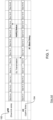
- HARQ transmission procedures in a 5G NR system are illustrated for gNB DL slots 102 and UE UL slots 104.
- HARQ resources are allocated where UE will transmit ACK status for PDSCH using the assigned HARQ resources.
- PUCCH HARQ resources are used to carry ACK / NACK status for DL transmission with predefined timing offset of K1 slots.
- the number of HARQ resources in PUCCH in an UL slot is based on number of DL scheduled users in a Transmit Time Interval (TTI) in a typical Frequency Division Duplexing (FDD) based configuration.
- TTI Transmit Time Interval
- FDD Frequency Division Duplexing
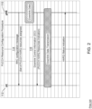
- FIG. 2 illustrates known methods for configuring HARQ resources. This type of configuration is done in two stages. These stages comprise: 1) the RRC 110 (Next Generation Node B - gNB) configures a set of HARQ resources 114 during attachment of UE 112 and 2) a unique HARQ resource from the set is allocated in Downlink Control Information (DCI) 116.
- RRC 110 Next Generation Node B - gNB
- DCI Downlink Control Information
- the possible set of HARQ resources that are assigned to UE 112 in the RRC configuration message during UE attachment and exact HARQ resources are indicated in the PUCCH resource indicator field of DCI 1_0 / 1_1.
- the UE 112 will use this indicated resource to transmit the HARQ status information in the PUCCH for every PDSCH transmission.
- FIG. 3 illustrates known methods for implementation of PUCCH transmission that results in significant interference in PUCCH transmission. It has been determined that significant degradation in DL throughput due to reception of PUCCH DTX (PUCCH Discontinuous Transmission) or NACK occurs when Inter-cell Interference (ICI) is present across the UEs.
- PUCCH DTX PUCCH Discontinuous Transmission
- NACK Inter-cell Interference
- UE 112 is connected to gNB 0 110 and UE 112' is connected to gNB 1 110'. Interference occurs between the PUCCH of UE 112 and UE 112'.
- RSRP Reference Signal Received Power
- FIG. 4 is a graph that provides information relating to PUCCH interference.
- the graph of FIG. 4 shows that approximately 40% Block Error Rate (BLER) is observed in the DL.
- BLER Block Error Rate
- the graph shows that PUCCH interference caused by PUCCH resource collision is significant and that many NACKs are received when UEs use PUCCH resources and Cyclic shifts are allocated in the same Resource Band across cells.
- the percentage of PUCCH NACK / DTX detection for UEs is relatively high, which causes the DL throughput to be significantly degraded. To improve the throughput in the DL, it is very important to increase the PUCCH HARQ detection probability.
- FIG. 5 illustrates known time and resource mapping of PUCCH HARQ resources for a 10 MHz bandwidth system.
- PUCCH Format 0 resources are used to transmit HARQ information.
- PUCCH Format 0 resources are configured to the UE by the higher layers, where configuration parameters include initialCyclicShift, nrOfSymbols, startingPRB and StartSymbol indexes. The combination of these parameters indicates unique HARQ F0 resources, which are separated by Time / Frequency / Code domain.
- these higher layer configured parameters are sent to the UE 112 through an RRC message during UE attachment.
- the Start Resource Block index for HARQ F0 resources (RB #11) is maintained constant across sectors. The result of this is that it will cause severe interference in UL reception of PUCCH and degradation in overall system performance.
- an Open Radio Access Network (O-RAN) system 100 is illustrated.
- a Distributed Unit (DU) server 120 is provided along with a Cell Site Router (CSR) 130.
- the CSR 30 allows the DU server 120 to communicate with Control Unit (CU) server 140 via mid-haul connection 132.
- Mid-haul connection 132 can be a public Wide Area Network (WAN) or a leased line connection over the WAN.
- the CU server 140 communicates with 5G Core equipment 150 via back-haul connection 142.
- the DU server 120 at remote cell site 100 communicates wirelessly with Radio Units (RUs) 112, 114, 116 via front-haul 122. It should be noted that while three RUs are illustrated, additional RUs may be connected to DU server 120.
- RUs Radio Units
- FIG. 7 a centralized Radio Resource Management (RRM) module 144 controlling resource allocation across sectors in a cell site is illustrated.
- the cellular / wireless communication system illustrated includes a group of cell sites 102, 104, 106 as per FIG. 6 , where each cell site may include multiple sectors (e.g., 1, 2, 3, 4 or more sectors), communicating with the set of UE's.
- RRM Radio Resource Management
- the RRM may be in a Central Unit-Control Plane (CU-CP) 140 controlling the PUCCH HARQ resources Resource Block locations for the sectors in all sites.
- CU-CP Central Unit-Control Plane
- a Media Access Control (MAC) Scheduler 122, 124, 126, in each sector is responsible to assign PUCCH HARQ resources through the resource indicator field in DCI to transmit acknowledgement status for PDSCH.
- the MAC Scheduler 122, 124, 126 assigns bandwidth resources to UE and is responsible for deciding on how UL and DL channels are used by the eNodeB and the UEs of a cell.
- the MAC Scheduler 122, 124, 126 is part of a DU 120 that is used for controlling the multi-user dynamic physical resource allocation. It functions to fulfill the QoS targets for each Data Radio Bearer (DRB).
- DRB Data Radio Bearer
- the system configuration according to the invention is directed to allocating PUCCH HARQ resources for the UE 112 that is separated by Frequency and/or Cyclic Shift for nearby sectors based on the Physical Cell Identity (PCI).
- PCI Physical Cell Identity
- the system configures the different start Physical Resource Block index of PUCCH HARQ resources and/or Cyclic Shift Index to maintain the orthogonality across nearby sectors.
- HARQ resources are offset by 'K' number of Resource Blocks in frequency, where 'K' is number of HARQ F0 resources required as per PUCCH resource design. It is given in the below equation.
- R B HARQ ⁇ FO , Start i R B HARQ ⁇ F 0 ⁇ Base + PC I i mod N ⁇ K RB HARQ ⁇ FO , Start i is the start Resource Block index of HARQ-F0 resources for a sector i.
- PCI i is the Physical Cell Identity (PCI) of a sector i.
- mod represents the modulo operation in Formula 1.
- mod operation returns the signed remainder of the division.
- PCI mod N represents, remainder of PCI divided by N.
- N is the number of considered sectors for HARQ resource orthogonalization.
- FIG. 8 illustrates PUCCH HARQ resources Resource Block and Cyclic index shifting for sectors Alpha, Beta and Gamma of FIG. 6 using the proposed method.
- RRM module 120 does not schedule any PUCCH resources on the same Resource Block with the same Cyclic Shift that would cause interference in PUCCH HARQ decoding in other sectors.
- RB HARQ - F 0- Base is fixed as Resource Block 11.
- PCI mod 3 0 for sector Alpha, hence there is no offset added for HARQ resources.
- RB HARQ ⁇ FO , Start i RB HARQ ⁇ F 0 ⁇ Base in this case.
- HARQ resources utilize Resource Blocks 11 - 14.
- Beta there is an offset that is added shifting HARQ resources to utilize Resource Blocks 15 - 18.
- Gamma there is another offset that is added shifting HARQ resources to utilize Resource Blocks 19 - 22.
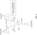
- FIG. 9 illustrates the implementation of the proposed method in a cell site scenario, which is notably different than the method illustrated in FIG. 3 .
- PUCCH HARQ frequency and Cyclic shift method PUCCH resources in Sector Beta do not interfere with Sector Alpha, increases the PUCCH HARQ detection capability for UE, 112, 112', 112".
- Each sector therefore creates no interference to uplink HARQ transmission in other sectors.
- a typical 3-sector site configuration is assumed in FIG. 9 .
- K is the number of available HARQ F0 resources in a sector.
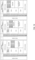
- FIG. 10 illustrates HARQ resource assignment using the proposed method in connection with a 5 MHz system.
- OFDM Orthogonal Frequency Division Multiplexing
- the system configures HARQ F0 resource with frequency offset of 2 Resource Blocks and Cyclic shift offset of 2 for different sectors for 5 MHz based systems.
- the system and method can further be applied to the following situations:
Landscapes
- Engineering & Computer Science (AREA)
- Signal Processing (AREA)
- Computer Networks & Wireless Communication (AREA)
- Mobile Radio Communication Systems (AREA)
Abstract
A Radio Access Network (RAN) system includes a group of cell sites where each cell site includes multiple sectors, and each sector communicates with UE, the system including a Radio Resource Controller (RRC) in Central Unit (CU) controlling PUCCH resources for the sectors, and a Media Access Control (MAC) Scheduler in each sector allocating resources for PUCCH HARQ transmissions in an orthogonal manner separated in time or frequency or cyclic shift to minimize the inter-carrier interference across the sectors to improve system throughput.
Description
- The present disclosure relates to systems and methods to improve the detectability of Hybrid Automatic Repeat reQuest (HARQ) transmission in Physical Uplink Control Channel (PUCCH), which increases the DownLink (DL) throughput of the system.
- Physical Uplink Control Channel (PUCCH) Hybrid Automatic Repeat reQuest (HARQ) resources are used to carry Acknowledgement (ACK) / Negative Acknowledgement (NACK) status for Downlink transmission with the predefined timing offset of K1 slots. An ACK or NACK is a short message sent by a receiver to a transmitter to indicate whether it has correctly or incorrectly received a data packet, respectively.
- In a typical Frequency Division Duplexing (FDD) based configuration, the number of HARQ resources in PUCCH in an UpLink (UL) slot is based on the number of DL scheduled users in a Transmit Time Interval (TTI). The procedure for PUCCH HARQ transmission for DL transmission is illustrated, for example, in
FIG. 1 . - As part of the PUCCH resource allocation procedure, the possible set of HARQ resources assigned to User Equipment (UE) in a Radio Resource Control (RRC) configuration message while the UE is attached and an exact HARQ resource, is indicated in the PUCCH resource indicator field of Downlink Control Information (DCI) 1_0 / 1_1. This procedure is illustrated in
FIG. 2 . UE will use this indicated resource to transmit the HARQ status information in the PUCCH for every Physical Downlink Shared Channel (PDSCH) transmission. - It has been observed that there is a significant degradation in DL throughput due to reception of PUCCH Discontinuous Transmission (PUCCH DTX) or NACK when Inter-cell Interference (ICI) is present across UE coupled to nearby sectors, which is illustrated in the configuration shown in
FIG. 3 . Typically, these issues are prevalent in cell edge scenarios. - Observations of PUCCH interference caused by PUCCH resource collision across sectors are illustrated in the chart depicted in
FIG. 4 . Notably,FIG. 4 illustrates that many NACKs are received when UE utilize PUCCH resources and cyclic shifts that are allocated in the same Resource Blocks across cells. In these situations, the percentage of PUCCH NACK / DTX detection for UEs has been observed to increase by as much as 40% causing Downlink throughput to significantly degrade. To improve throughput in Downlink, it is important to increase the PUCCH HARQ detection probability. However, current methods and system configurations do not allow for increased PUCCH HARQ detection probability. - Based on existing designs, PUCCH HARQ resources are assigned across sectors in the same frequency locations and use the same cyclic shifts. Additionally, PUCCH
Format 0 resources are used to transmit HARQ information. As per 3GPP specifications, PUCCHFormat 0 resources are configured to the UE by the higher layers, where configuration parameters include initialCyclicShift, nrOfSymbols, startingPRB and StartSymbol indexes. Combinations of these parameters indicate unique HARQ F0 resources are separated by Time / Frequency / Code domain. Typically, these higher-layer configured parameters are sent to the UE through an RRC message during UE attachment. - The existing design of time and resource mapping of PUCCH HARQ resources for a 10 MHz bandwidth system is given in
FIG. 5 . Start Resource Block index for HARQ F0 resources (Resource Block #11) is maintained the same acrosssectors FIG. 4 . - The above-described problem can be mitigated to a limited extent by positioning PUCCH HARQ resources in different time positions in a slot in different sectors so that they do not interfere with each other. Different Time positions in a slot refers to: allocating PUCCH HARQ resources in a different symbol within a slot (but this solution is not optimal because interference can still occur from nearby cell PUSCH). In other words, the PUCCH can still be interfered with from the Physical Uplink Shared Channel (PUSCH) from other sectors. Additionally, it requires strict resource planning for PUCCH transmission to maximize the number of Resource Blocks or Resource Elements for PUSCH transmission, which is difficult to achieve.
- Accordingly, there is a need for a system that overcomes, alleviates, and/or mitigates one or more of the aforementioned and other deleterious effects of the prior art.
- Accordingly, what is needed is a system and method that avoids PUCCH HARQ interference with nearby sectors.
- It is further desired to provide a system and method for allocating PUCCH HARQ resources for a sector that is separated by Frequency or Cyclic Shift from nearby sectors.
- It is still further desired to provide a system and method that configures a Physical Resource Block (PRB) index with an offset for PUCCH HARQ resources and/or Cyclic Shift Index for each sector based on Physical Cell Identity (PCI).
- It also desired to provide a system and method that avoids configuring PUCCH HARQ resources on the same PRB and/or Cyclic Shift index in a PUCCH symbol for nearby sectors to avoid interference in HARQ decoding at an evolved Node B / Next Generation Node B (eNB/gNB) system.
- Accordingly, in one configuration, a method is provided that facilitates allocation of PUCCH HARQ resources for a sector that is separated by frequency and/or cyclic shift with the nearby sectors. This allows for avoidance of PUCCH HARQ interference with the nearby sectors. The system configures the PRB index with an offset for PUCCH HARQ resources and/or cyclic shift index for each sector based on PCI. This ensures that orthogonal transmission is maintained across nearby sectors.
- It was previously stated that the problem identified in
FIGS. 4 and5 , could be slightly mitigated by positioning PUCCH HARQ resources in different time positions in a slot in different sectors so that they do not interfere with each other and that different time positions in a slot refers to: allocating PUCCH HARQ resources in a different symbol within a slot. This is a suboptimal solution due to interference from nearby cell PUSCH. - In contrast, the proposed solution considers the one particular symbol in a slot reserved for PUCCH HARQ transmission, which will not be used for PUSCH in any cells. That symbol in a slot will be shared among nearby cells.
- For example, the former case is:
- Cell 0 - Symbol a in
slot 0, - Cell 1 - Symbol b in
slot 0, - Cell 2 - Symbol c in
slot 0, and so on. - In contrast, the proposed approach is as follows:
- Cell 0 - Symbol x in
slot 0 - Cell 1 - Symbol x in
slot 1, - Cell 2 - Symbol x in
slot 2, and so on. - As can be seen, the previous approach utilized different symbols in the same slot in different cells, whereas, the present approach may utilize the same symbol in different slots in different cells.
- For this application the following terms and definitions shall apply:
- The term network as used herein includes both networks and internetworks of all kinds, including the Internet, and is not limited to any particular type of network or inter-network.
- The terms first and second are used to distinguish one element, set, data, object or thing from another, and are not used to designate relative position or arrangement in time.
- The terms coupled, coupled to, coupled with, connected, connected to, and connected with as used herein each mean a relationship between or among two or more devices, apparatus, files, programs, applications, media, components, networks, systems, subsystems, and/or means, constituting any one or more of (a) a connection, whether direct or through one or more other devices, apparatus, files, programs, applications, media, components, networks, systems, subsystems, or means, (b) a communications relationship, whether direct or through one or more other devices, apparatus, files, programs, applications, media, components, networks, systems, subsystems, or means, and/or (c) a functional relationship in which the operation of any one or more devices, apparatus, files, programs, applications, media, components, networks, systems, subsystems, or means depends, in whole or in part, on the operation of any one or more others thereof.
- The term Automatic Repeat reQuest (ARQ) as used herein is a transmission protocol used in communication systems, including LTE networks, to ensure the reliable delivery of data. It is a method for detecting and correcting errors that may occur during data transmission. ARQ works by requiring a receiver to send an acknowledgment (ACK) (message sent by the receiver indicating that it has correctly received a message) and timeouts (time periods allowed to elapse before an acknowledgment is to be received). If the receiver detects errors in the data packet, it sends a negative acknowledgment message to the sender, indicating that the packet needs to be retransmitted.
- The term Hybrid Automatic Repeat reQuest (HARQ) as used herein is a communication protocol that allows the sender to detect and correct errors in transmitted data. It is a combination of high-rate forward error correction (FEC) and automatic repeat request (ARQ) error-control and works by using a combination of retransmissions and error correction codes to ensure that the data is transmitted and received correctly. HARQ enables faster recovery from errors in cellular networks by storing corrupted packets in the receiving device rather than discarding them. A sender will only retransmit the erroneous bits or packets of information not properly received.
- The term Forward error correction (FEC) or channel coding as used herein is a technique used for controlling errors in data transmission over a communication channel.
- The term Block Error Rate (BLER) as used herein is a ratio of the number of erroneous blocks to the total number of blocks transmitted on a digital circuit.
- The term DownLink (DL) as used herein is data flow towards the radiating antenna.
- The term UpLink (UL) as used herein is data flow away from the radiating antenna.
- The term O-RAN Control Unit (CU) as used herein is a logical node hosting PDCP, RRC, SDAP and other control functions.
- The term O-RAN Distributed Unit (DU) as used herein is a logical node hosting RLC/MAC/High-PHY layers based on a lower layer functional split.
- The term O-RAN Radio Unit (RU) as used herein is a logical node hosting Low-PHY layer and RF processing based on a lower layer functional split. This is similar to 3GPP's "TRP" or "RRH" but more specific in including the Low-PHY layer (FFT/iFFT, PRACH extraction).
- The term Third generation partnership project (3GPP) as used herein is a partnership of seven telecommunications standard development organizations that produces reports and specifications for mobile networks.
- The term g NodeB (gNB) as used herein is the radio base station in 5G NR networks. These radio base stations (nodes) are the cell towers mobile operators use to connect mobile phones.
- The term User Equipment (UE) as used herein refers to the end-user device that connects to a wireless network to access various services and applications.
- The term Radio Resource Control (RRC) as used herein is a vital protocol in mobile communication networks that manages the establishment, maintenance, and release of radio connections between mobile devices and the network. It also ensures efficient utilization of radio resources, facilitates mobility management, and optimizes network performance to provide reliable communication services to users.
- The term Physical Uplink Control Channel (PUCCH) as used herein is a channel that is designed to carry UCI (Uplink Control Information).
- The term Physical Uplink Share Channel (PUSCH) as used herein is a channel responsible for carrying user data from the User Equipment (UE) to the base station.
- The term Physical Downlink Control Channel (PDCCH) as used herein is a channel that controls the transmission and reception of UL and DL data by transmitting Downlink Control Information (DCI).
- The term Radio Access Network (RAN) as used herein is the part of a communications system that traditionally connects cellular wireless capable (e.g., 4G LTE, 5G) devices back to a public and / or private mobile core network via an existing network backbone.
- The term Physical Resource Block (PRB) as used herein is a block made up of 12 consecutive subcarriers.
- The term Reference Signal Receiving Power (RSRP) as used herein represents the power level of the DL reference signals transmitted by a 5G base station as received by the user equipment (UE) or device.
- The term Signal to Interference plus Noise Ratio (SINR) as used herein measures the ratio of the received signal power to the sum of interference and noise power.
- In one configuration, a cellular communication system is provided comprising: a group of cell sites, each has 1, 2, 3 or 4 sectors, communicating with the set of User Equipment, and a Radio Resource Controller (RRC) in a Control Unit-Control Plane (CU-CP) controlling the PUCCH resources for the sectors in all sites. The system further comprises a Media Access Control (MAC) Scheduler in each sector that allocates resources for PUCCH HARQ transmissions in an orthogonal way, which are separated in Time and/or frequency and/or Cyclic shift to minimize Inter-Carrier Interference across the sectors.
- In another configuration, a Radio Access Network (RAN) system is provided comprising: a radio unit (RU) coupled to a plurality of user equipment (UE), the RU having a plurality of sectors, and a radio resource controller (RRC) in a control unit (CU) server controlling physical uplink control channel (PUCCH) resources for the plurality of sectors. The system further comprises: a media access control (MAC) scheduler for each of the plurality of sectors allocating resources for PUCCH hybrid automatic repeat request (HARQ) transmissions in an orthogonal manner, which are separated in time, frequency or cyclic shift to minimize the inter-carrier interference across the plurality of sectors.
- The above-described and other features and advantages of the present disclosure will be appreciated and understood by those skilled in the art from the following detailed description, drawings, and appended claims.
-
-
FIG. 1 illustrates HARQ transmission procedures in a 5G NR system according to the prior art; -
FIG. 2 illustrates a method for configuring HARQ resources according to the prior art; -
FIG. 3 illustrates the known implementation deployed, which creates significant interference in PUCCH transmission according to prior art systems; -
FIG. 4 illustrates PUCCH interference in prior art systems; -
FIG. 5 illustrates known time and resource mapping design for PUCCH HARQ resources comprising a 10 MHz bandwidth system in prior art systems; -
FIG. 6 illustrates a Radio Access Network (RAN) according to one configuration of the present invention; -
FIG. 7 illustrates a centralized Radio Resource Management (RRM) module controlling resource allocation across a sector in a RAN according to the system ofFIG. 6 ; -
FIG. 8 illustrates PUCCH HARQ Resource Block and Cyclic index shifting for sectors Alpha, Beta and Gamma according to the system and method ofFIG. 7 ; -
FIG. 9 illustrates the implementation of the system and method according toFIGS. 7 &8 in a typical cell site configuration; and -
FIG. 10 illustrates the HARQ resource assignment according to the system and method ofFIGS. 6-9 in connection with a 5 MHz system. - Referring now to the drawings, wherein like reference numerals designate corresponding structure throughout the views.
- Referring now to
FIG. 1 , HARQ transmission procedures in a 5G NR system are illustrated forgNB DL slots 102 andUE UL slots 104. For each PDSCH transmission, HARQ resources are allocated where UE will transmit ACK status for PDSCH using the assigned HARQ resources. - PUCCH HARQ resources are used to carry ACK / NACK status for DL transmission with predefined timing offset of K1 slots. The number of HARQ resources in PUCCH in an UL slot is based on number of DL scheduled users in a Transmit Time Interval (TTI) in a typical Frequency Division Duplexing (FDD) based configuration.
-
FIG. 2 illustrates known methods for configuring HARQ resources. This type of configuration is done in two stages. These stages comprise: 1) the RRC 110 (Next Generation Node B - gNB) configures a set ofHARQ resources 114 during attachment ofUE 112 and 2) a unique HARQ resource from the set is allocated in Downlink Control Information (DCI) 116. - As part of the PUCCH resource allocation procedure, in relation to the first step described above, the possible set of HARQ resources that are assigned to
UE 112 in the RRC configuration message during UE attachment and exact HARQ resources are indicated in the PUCCH resource indicator field of DCI 1_0 / 1_1. TheUE 112 will use this indicated resource to transmit the HARQ status information in the PUCCH for every PDSCH transmission. -
FIG. 3 illustrates known methods for implementation of PUCCH transmission that results in significant interference in PUCCH transmission. It has been determined that significant degradation in DL throughput due to reception of PUCCH DTX (PUCCH Discontinuous Transmission) or NACK occurs when Inter-cell Interference (ICI) is present across the UEs. In the case illustrated inFIG. 3 ,UE 112 is connected togNB 0 110 and UE 112' is connected togNB 1 110'. Interference occurs between the PUCCH ofUE 112 and UE 112'. - It has been observed that typically interference will occur in cell edge scenarios where Reference Signal Received Power (RSRP) of the received signal is below -100 dBm and the respective SINR is less than 0 dB.
-
FIG. 4 is a graph that provides information relating to PUCCH interference. The graph ofFIG. 4 shows that approximately 40% Block Error Rate (BLER) is observed in the DL. - The graph shows that PUCCH interference caused by PUCCH resource collision is significant and that many NACKs are received when UEs use PUCCH resources and Cyclic shifts are allocated in the same Resource Band across cells. The percentage of PUCCH NACK / DTX detection for UEs is relatively high, which causes the DL throughput to be significantly degraded. To improve the throughput in the DL, it is very important to increase the PUCCH HARQ detection probability.
-
FIG. 5 illustrates known time and resource mapping of PUCCH HARQ resources for a 10 MHz bandwidth system.PUCCH Format 0 resources are used to transmit HARQ information. As per 3GPP specifications TS 38.213 section 9.2.1,PUCCH Format 0 resources are configured to the UE by the higher layers, where configuration parameters include initialCyclicShift, nrOfSymbols, startingPRB and StartSymbol indexes. The combination of these parameters indicates unique HARQ F0 resources, which are separated by Time / Frequency / Code domain. Typically, these higher layer configured parameters are sent to theUE 112 through an RRC message during UE attachment. - As shown in
FIG. 5 , the Start Resource Block index for HARQ F0 resources (RB #11) is maintained constant across sectors. The result of this is that it will cause severe interference in UL reception of PUCCH and degradation in overall system performance. - Referring now to
FIG. 6 , an Open Radio Access Network (O-RAN)system 100 is illustrated. At the remote cell site location 100 a Distributed Unit (DU)server 120 is provided along with a Cell Site Router (CSR) 130. TheCSR 30 allows theDU server 120 to communicate with Control Unit (CU)server 140 viamid-haul connection 132.Mid-haul connection 132 can be a public Wide Area Network (WAN) or a leased line connection over the WAN. TheCU server 140 communicates with5G Core equipment 150 via back-haul connection 142. - The
DU server 120 atremote cell site 100 communicates wirelessly with Radio Units (RUs) 112, 114, 116 via front-haul 122. It should be noted that while three RUs are illustrated, additional RUs may be connected toDU server 120. - Turning to
FIG. 7 , a centralized Radio Resource Management (RRM)module 144 controlling resource allocation across sectors in a cell site is illustrated. The cellular / wireless communication system illustrated includes a group ofcell sites FIG. 6 , where each cell site may include multiple sectors (e.g., 1, 2, 3, 4 or more sectors), communicating with the set of UE's. - The RRM may be in a Central Unit-Control Plane (CU-CP) 140 controlling the PUCCH HARQ resources Resource Block locations for the sectors in all sites.
- A Media Access Control (MAC)
Scheduler MAC Scheduler MAC Scheduler DU 120 that is used for controlling the multi-user dynamic physical resource allocation. It functions to fulfill the QoS targets for each Data Radio Bearer (DRB). - The system configuration according to the invention is directed to allocating PUCCH HARQ resources for the
UE 112 that is separated by Frequency and/or Cyclic Shift for nearby sectors based on the Physical Cell Identity (PCI). - In one configuration, the system configures the different start Physical Resource Block index of PUCCH HARQ resources and/or Cyclic Shift Index to maintain the orthogonality across nearby sectors. HARQ resources are offset by 'K' number of Resource Blocks in frequency, where 'K' is number of HARQ F0 resources required as per PUCCH resource design. It is given in the below equation.


Formula 1. mod operation returns the signed remainder of the division. For example, PCI mod N represents, remainder of PCI divided by N. N is the number of considered sectors for HARQ resource orthogonalization. -
FIG. 8 illustrates PUCCH HARQ resources Resource Block and Cyclic index shifting for sectors Alpha, Beta and Gamma ofFIG. 6 using the proposed method.RRM module 120 does not schedule any PUCCH resources on the same Resource Block with the same Cyclic Shift that would cause interference in PUCCH HARQ decoding in other sectors. - As illustrated in
FIG. 8 for 10 MHz bandwidth operation, RB HARQ-F0-Base is fixed asResource Block 11.PCI mod 3 = 0 for sector Alpha, hence there is no offset added for HARQ resources.
- However, for Beta, there is an offset that is added shifting HARQ resources to utilize Resource Blocks 15 - 18. Likewise, for Gamma, there is another offset that is added shifting HARQ resources to utilize Resource Blocks 19 - 22.
-
FIG. 9 illustrates the implementation of the proposed method in a cell site scenario, which is notably different than the method illustrated inFIG. 3 . Using PUCCH HARQ frequency and Cyclic shift method, PUCCH resources in Sector Beta do not interfere with Sector Alpha, increases the PUCCH HARQ detection capability for UE, 112, 112', 112". - Each sector therefore creates no interference to uplink HARQ transmission in other sectors. A typical 3-sector site configuration is assumed in
FIG. 9 . - To help with operation and deployment, the configuration of sectors can be done automatically by using PCI%3 (where % is modulo operation). That is, if
PCI% 3 = 0, then configure PUCCH HARQ resources with RB index X andCS 0 and so on. This would reduce the operational and deployment complexity. - That is,
Table 1 If PCI % 3 = 0Then configure PUCCH HARQ resources with RB index N, CS Index 0If PCI % 3 = 1Then configure PUCCH HARQ resources with RB index N+K, CS Index offset δ If PCI % 3 = 2Then configure PUCCH HARQ resources with RB index N +2K, CS Index offset 2 δ - Where K is the number of available HARQ F0 resources in a sector.
- For example, configurations of PUCCH HARQ F0 resources for 10 MHz systems based on proposed solution is as follows,
Table 2 If PCI % 3 = 0PUCCH HARQ RB start Index 11,CS 0If PCI % 3 = 1PUCCH HARQ RB start Index 15,CS 2If PCI % 3 = 2PUCCH HARQ RB start Index 19,CS 4 -
FIG. 10 illustrates HARQ resource assignment using the proposed method in connection with a 5 MHz system. As can be seen, for a carrier with a 5 MHz bandwidth, 2 Orthogonal Frequency Division Multiplexing (OFDM) symbols for PUCCH resource transmission are required due to less availability of resources. - The system configures HARQ F0 resource with frequency offset of 2 Resource Blocks and Cyclic shift offset of 2 for different sectors for 5 MHz based systems.
- It should be noted that, while various functions and methods have been described and presented in a sequence of steps, the sequence has been provided merely as an illustration of one advantageous embodiment, and that it is not necessary to perform these functions in the specific order illustrated. It is further contemplated that any of these steps may be moved and/or combined relative to any of the other steps. In addition, it is still further contemplated that it may be advantageous, depending upon the application, to utilize all or any portion of the functions described herein.
- The system and method can further be applied to the following situations:
- 1) For higher UL bandwidth transmissions, the frequency offset between PUCCH HARQ resources can be multiples of the parameter K. It depends on the available Bandwidth for PUCCH transmissions.
- 2) The concept can be utilized in PUCCH long format transmission for allocating HARQ resources orthogonally across sectors.
- 3) If there are more than 1 OFDM symbols reserved for PUCCH transmission, orthogonality across the PUCCH HARQ resources can be maintained across the symbols with / without frequency shifting.
- 4) Frequency offset across the PUCCH resource depends on the deployment scenarios of sectors within a site and interference pattern.
- While the present disclosure has been described with reference to one or more exemplary embodiments, it will be understood by those skilled in the art that various changes may be made and equivalents may be substituted for elements thereof without departing from the scope of the present disclosure. In addition, many modifications may be made to adapt a particular situation or material to the teachings of the disclosure without departing from the scope thereof. Therefore, it is intended that the present disclosure not be limited to the particular embodiment(s) disclosed as the best mode contemplated, but that the disclosure will include all embodiments falling within the scope of the appended claims.
Claims (15)
- A Radio Access Network (RAN) system comprising:a radio unit (RU) coupled to a plurality of user equipment (UE), the RU having a plurality of sectors;a radio resource controller (RRC) in a control unit (CU) server controlling physical uplink control channel (PUCCH) resources for the plurality of sectors;a media access control (MAC) scheduler for each of the plurality of sectors allocating resources for PUCCH hybrid automatic repeat request (HARQ) transmissions in an orthogonal manner, which are separated in time, frequency or cyclic shift to minimize the inter-carrier interference across the plurality of sectors.
- The RAN system of claim 1, wherein the allocation of resources is selected from the group consisting of:configuring a physical resource block index with an offset; orconfiguring a cyclic shift index for each sector based on physical cell identity (PCI).
- The RAN system of claim 1, wherein said RU comprises a plurality of RUs each RU having a plurality of sectors, said RRC controls PUCCH resources for all of the plurality of sectors, and wherein a MAC scheduler is provided for each the plurality of sectors where each MAC scheduler allocates the resources for PUCCH HARQ transmissions in an orthogonal manner across the plurality of sectors.
- The RAN system of claim 3, wherein when the plurality of sectors comprises three sectors, said RRC configures different PUCCH resources separated by frequency and cyclic shift to the three sectors.
- The RAN system of claim 4, wherein the system comprises a 10MHz system and the three sectors comprise first, second and third sectors.
- The RAN system of claim 5, wherein configurations of PUCCH HARQ F0 resources,starts at index 11 for the first sector;starts at index 15 for the second sector; andstarts at index 19 for the third sector.
- The RAN system of claim 4, wherein the system comprises a 5MHz system and the three sectors comprise first, second and third sectors.
- The RAN system of claim 7, wherein configurations of PUCCH HARQ F0 resources,starts at index 13 for the first sector;starts at index 15 for the second sector; andstarts at index 17 for the third sector.
- The RAN system of claim 1, wherein the RRC configures different PUCCH HARQ resources separated in frequency or cyclic shift to each sector in a RU.
- The RAN system of claim 1, wherein said RRC does not configure PUCCH HARQ resources on the same frequency or cyclic shift for adjacent sectors to avoid causing interference in uplink HARQ detection.
- The RAN system of claim 1, wherein said RRC configures an offset for HARQ resource blocks (RBs) based on physical cell identity (PCI) that is based on the overall available PUCCH resources in a system.
- The RAN system of claim 1, wherein said RRC uses physical cell identity (PCI) to automatically configure frequency positions of PUCCH HARQ resources for each sector according to the following equation:


- The RAN system of claim 1, wherein said MAC Scheduler in each of the plurality of sectors assigns PUCCH HARQ resources through a resource indicator field in downlink control information (DCI) to transmit acknowledgement status for physical downlink shared channel (PDSCH).
- The RAN system of claim 1, wherein the system comprises a plurality of RUs where each RU has an RRC;
wherein the allocation of resources comprises using one symbol x in a slot reserved for PUCCH HARQ transmission, which symbol will not be used for PUSCH in any RU and that symbol will be shared among adjacent RUs. - The RAN system of claim 14 wherein the plurality of RUs comprises Cell 0, Cell 1, and Cell 2, and wherein,Cell 0 uses symbol x in slot 0,Cell 1 uses symbol x in slot 1, andCell 2 uses symbol x in slot 2.
Applications Claiming Priority (2)
| Application Number | Priority Date | Filing Date | Title |
|---|---|---|---|
| IN202321031902 | 2023-05-04 | ||
| US18/635,603 US20240372656A1 (en) | 2023-05-04 | 2024-04-15 | Downlink Throughput of 5G NR Using PUCCH HARQ Resource Assignment |
Publications (1)
| Publication Number | Publication Date |
|---|---|
| EP4462714A1 true EP4462714A1 (en) | 2024-11-13 |
Family
ID=91022635
Family Applications (1)
| Application Number | Title | Priority Date | Filing Date |
|---|---|---|---|
| EP24174037.2A Pending EP4462714A1 (en) | 2023-05-04 | 2024-05-03 | Improving downlink throughput of 5g nr using pucch harq resource assignment |
Country Status (1)
| Country | Link |
|---|---|
| EP (1) | EP4462714A1 (en) |
Citations (2)
| Publication number | Priority date | Publication date | Assignee | Title |
|---|---|---|---|---|
| US20130148617A1 (en) * | 2010-08-16 | 2013-06-13 | Pantech Co., Ltd. | Device and method for transmitting control information in multi-carrier system |
| US20200067680A1 (en) * | 2017-05-03 | 2020-02-27 | Idac Holdings, Inc. | Methods, systems, and apparatus for transmitting uplink control information |
-
2024
- 2024-05-03 EP EP24174037.2A patent/EP4462714A1/en active Pending
Patent Citations (2)
| Publication number | Priority date | Publication date | Assignee | Title |
|---|---|---|---|---|
| US20130148617A1 (en) * | 2010-08-16 | 2013-06-13 | Pantech Co., Ltd. | Device and method for transmitting control information in multi-carrier system |
| US20200067680A1 (en) * | 2017-05-03 | 2020-02-27 | Idac Holdings, Inc. | Methods, systems, and apparatus for transmitting uplink control information |
Similar Documents
| Publication | Publication Date | Title |
|---|---|---|
| CN111247857B (en) | Method and device for transmitting or receiving signals in wireless communication system | |
| US8009782B2 (en) | Downscaling system bandwidth | |
| JP7302482B2 (en) | Communication device and communication method | |
| US11849479B2 (en) | Base stations and methods | |
| EP3665842B1 (en) | Multiple slot long physical uplink control channel (pucch) design for 5th generation (5g) new radio (nr) | |
| CN110352582B (en) | Uplink signal transmission or reception method and device thereof in wireless communication system | |
| JP4913222B2 (en) | Wireless communication system, mobile station apparatus, wireless communication method, and integrated circuit | |
| JP6174810B2 (en) | HARQ feedback using carrier aggregation | |
| CN109845180B (en) | Method for transmitting or receiving uplink signal for terminal supporting short transmission time interval in wireless communication system and apparatus therefor | |
| EP2915393B1 (en) | Systems and methods for carrier aggregation | |
| US8885556B2 (en) | Method for performing a HARQ in a multiple carrier system | |
| CN103201968B (en) | Communication method and device in wireless communication system | |
| EP3567760A1 (en) | Method for controlling cross-link interference, and apparatus therefor | |
| CN120812751A (en) | Reducing latency of physical channels in LTE networks | |
| CN111106921A (en) | Delay Reduction Techniques in Wireless Communication | |
| WO2017165198A1 (en) | User equipment, base station and methods to drop a pucch if colliding with a s-pucch in the same interval | |
| TWI607636B (en) | Method and apparatus for communication, related computer program, and base station or user equipment | |
| WO2018018620A1 (en) | Method of feeding back ack/nack information, terminal equipment, and network equipment | |
| US20250212257A1 (en) | Wireless communication method, terminal device, and network device | |
| EP3125459A1 (en) | Communication method for dual connectivity and apparatus using same | |
| US20250344229A1 (en) | Sidelink transmission method and terminal device | |
| US20200336927A1 (en) | Method and device for wireless communication in ue and base station | |
| JP5575819B2 (en) | Wireless communication system, mobile station apparatus, wireless communication method, and integrated circuit | |
| US20240372656A1 (en) | Downlink Throughput of 5G NR Using PUCCH HARQ Resource Assignment | |
| JP2017208842A (en) | HARQ feedback using carrier aggregation |
Legal Events
| Date | Code | Title | Description |
|---|---|---|---|
| PUAI | Public reference made under article 153(3) epc to a published international application that has entered the european phase |
Free format text: ORIGINAL CODE: 0009012 |
|
| STAA | Information on the status of an ep patent application or granted ep patent |
Free format text: STATUS: REQUEST FOR EXAMINATION WAS MADE |
|
| 17P | Request for examination filed |
Effective date: 20240503 |
|
| AK | Designated contracting states |
Kind code of ref document: A1 Designated state(s): AL AT BE BG CH CY CZ DE DK EE ES FI FR GB GR HR HU IE IS IT LI LT LU LV MC ME MK MT NL NO PL PT RO RS SE SI SK SM TR |