EP4462713A1 - Port mapping method for sounding reference signal, and terminal - Google Patents

Port mapping method for sounding reference signal, and terminal Download PDF

Info

Publication number
EP4462713A1
EP4462713A1 EP23737178.6A EP23737178A EP4462713A1 EP 4462713 A1 EP4462713 A1 EP 4462713A1 EP 23737178 A EP23737178 A EP 23737178A EP 4462713 A1 EP4462713 A1 EP 4462713A1
Authority
EP
European Patent Office
Prior art keywords
srs
ports
port
comb
mod
Prior art date
Legal status (The legal status is an assumption and is not a legal conclusion. Google has not performed a legal analysis and makes no representation as to the accuracy of the status listed.)
Pending
Application number
EP23737178.6A
Other languages
German (de)
French (fr)
Other versions
EP4462713A4 (en
Inventor
Kaili ZHENG
Yuan Shi
Tamrakar Rakesh
Current Assignee (The listed assignees may be inaccurate. Google has not performed a legal analysis and makes no representation or warranty as to the accuracy of the list.)
Vivo Mobile Communication Co Ltd
Original Assignee
Vivo Mobile Communication Co Ltd
Priority date (The priority date is an assumption and is not a legal conclusion. Google has not performed a legal analysis and makes no representation as to the accuracy of the date listed.)
Filing date
Publication date
Application filed by Vivo Mobile Communication Co Ltd filed Critical Vivo Mobile Communication Co Ltd
Publication of EP4462713A1 publication Critical patent/EP4462713A1/en
Publication of EP4462713A4 publication Critical patent/EP4462713A4/en
Pending legal-status Critical Current

Links

Images

Classifications

    • HELECTRICITY
    • H04ELECTRIC COMMUNICATION TECHNIQUE
    • H04LTRANSMISSION OF DIGITAL INFORMATION, e.g. TELEGRAPHIC COMMUNICATION
    • H04L5/00Arrangements affording multiple use of the transmission path
    • H04L5/003Arrangements for allocating sub-channels of the transmission path
    • H04L5/0048Allocation of pilot signals, i.e. of signals known to the receiver
    • HELECTRICITY
    • H04ELECTRIC COMMUNICATION TECHNIQUE
    • H04LTRANSMISSION OF DIGITAL INFORMATION, e.g. TELEGRAPHIC COMMUNICATION
    • H04L5/00Arrangements affording multiple use of the transmission path
    • H04L5/003Arrangements for allocating sub-channels of the transmission path
    • H04L5/0048Allocation of pilot signals, i.e. of signals known to the receiver
    • H04L5/0051Allocation of pilot signals, i.e. of signals known to the receiver of dedicated pilots, i.e. pilots destined for a single user or terminal
    • HELECTRICITY
    • H04ELECTRIC COMMUNICATION TECHNIQUE
    • H04LTRANSMISSION OF DIGITAL INFORMATION, e.g. TELEGRAPHIC COMMUNICATION
    • H04L27/00Modulated-carrier systems
    • H04L27/26Systems using multi-frequency codes
    • H04L27/2601Multicarrier modulation systems
    • H04L27/2602Signal structure
    • H04L27/26035Maintenance of orthogonality, e.g. for signals exchanged between cells or users, or by using covering codes or sequences
    • HELECTRICITY
    • H04ELECTRIC COMMUNICATION TECHNIQUE
    • H04LTRANSMISSION OF DIGITAL INFORMATION, e.g. TELEGRAPHIC COMMUNICATION
    • H04L27/00Modulated-carrier systems
    • H04L27/26Systems using multi-frequency codes
    • H04L27/2601Multicarrier modulation systems
    • H04L27/2602Signal structure
    • H04L27/2605Symbol extensions, e.g. Zero Tail, Unique Word [UW]
    • HELECTRICITY
    • H04ELECTRIC COMMUNICATION TECHNIQUE
    • H04LTRANSMISSION OF DIGITAL INFORMATION, e.g. TELEGRAPHIC COMMUNICATION
    • H04L27/00Modulated-carrier systems
    • H04L27/26Systems using multi-frequency codes
    • H04L27/2601Multicarrier modulation systems
    • H04L27/2602Signal structure
    • H04L27/261Details of reference signals
    • H04L27/2613Structure of the reference signals
    • HELECTRICITY
    • H04ELECTRIC COMMUNICATION TECHNIQUE
    • H04LTRANSMISSION OF DIGITAL INFORMATION, e.g. TELEGRAPHIC COMMUNICATION
    • H04L5/00Arrangements affording multiple use of the transmission path
    • H04L5/0001Arrangements for dividing the transmission path
    • H04L5/0003Two-dimensional division
    • H04L5/0005Time-frequency
    • HELECTRICITY
    • H04ELECTRIC COMMUNICATION TECHNIQUE
    • H04LTRANSMISSION OF DIGITAL INFORMATION, e.g. TELEGRAPHIC COMMUNICATION
    • H04L5/00Arrangements affording multiple use of the transmission path
    • H04L5/0001Arrangements for dividing the transmission path
    • H04L5/0014Three-dimensional division
    • H04L5/0023Time-frequency-space

Definitions

  • This application pertains to the field of communications technologies, and in particular, relates to a port mapping method for sounding reference signals and a terminal.
  • Sounding Reference Signal can be used for beam management (beam management), codebook (codebook)-based transmission, non-codebook (non-codebook)-based transmission, and antenna switching (antenna switching) transmission.
  • a terminal can obtain a plurality of SRS resource sets through higher-layer signaling, and configuration for each SRS resource set includes configurations of its usage, periodic characteristics, or the like.
  • SRS resources can occupy the last 6 symbols in one slot, and configuration can be made through higher-layer signaling to occupy 1/2/4 symbol for SRS transmission, and supports a comb-like structure such as comb-2 and comb-4 in frequency domain. Release-17 is enhanced on the basis of Release-15/16.
  • a starting symbol position of SRS resources may be any symbol in one slot.
  • a comb-8 structure is also supported.
  • the existing NR protocol supports only the number of SRS ports being 1, 2, and 4. To further improve the performance of uplink transmission, it is necessary to support a larger quantity of SRS ports, for example, the number of SRS ports is 6 and 8. Because orthogonality between different SRS ports needs to be guaranteed as much as possible, existing SRS port mapping modes cannot be fully applied to a case with the number of SRS ports being 6 and 8.
  • Embodiments of this application provide a port mapping method for sounding reference signals and a terminal, which can resolve the problem of port mapping for SRSs with the number of ports being 6 and 8.
  • a port mapping method for sounding reference signals includes:
  • a port mapping apparatus for sounding reference signals including: a first determining unit, configured to: in a case that the number of ports for a first sounding reference signal SRS is 6 or 8, determine, for a terminal, a cyclic shift CS corresponding to each port for the first SRS and/or a comb (comb) position mapped by the each port for the first SRS; where a comb structure size of the first SRS is N, and N is 2, 4, 6, or 8.
  • a terminal includes a processor and a memory, and a program or instructions executable on the processor are stored in the memory.
  • the program or the instructions are executed by the processor, the steps of the method according to the first aspect are implemented.
  • a terminal including a processor and a communication interface, where the processor is configured to: in a case that the number of ports for a first sounding reference signal SRS is 6 or 8, determine a cyclic shift CS corresponding to each port for the first SRS and/or a comb (comb) position mapped by the each port for the first SRS; where a comb structure size of the first SRS is N, and N is 2, 4, 6, or 8.
  • a readable storage medium where a program or instructions are stored in the readable storage medium, and when the program or the instructions are executed by a processor, the steps of the method according to the first aspect are implemented.
  • a chip is provided, where the chip includes a processor and a communication interface, the communication interface is coupled to the processor, and the processor is configured to run a program or instructions to implement the method according to the first aspect.
  • a computer program/program product is provided, where the computer program/program product is stored in a storage medium, and the computer program/program product is executed by at least one processor to implement the steps of the port mapping method for sounding reference signals according to the first aspect.
  • the embodiments of this application provide a port mapping solution used for cases that different combs are configured for SRSs when the number of ports for SRSs is 6 and 8, which can improve the orthogonality of SRS reference signal transmission on each port, thereby improving performance of uplink transmission.
  • first and second are intended to distinguish between similar objects but do not necessarily indicate a specific order or sequence. It should be understood that the terms used in this way is interchangeable in appropriate circumstances so that the embodiments of this application can be implemented in other orders than the order illustrated or described herein, and “first” and “second” are usually for distinguishing same-type objects but not limiting the number of objects, for example, there may be one or more first objects.
  • first and second are usually for distinguishing same-type objects but not limiting the number of objects, for example, there may be one or more first objects.
  • “and/or” in this specification and claims indicates at least one of connected objects, and the symbol “/" generally indicates that the associated objects are in an "or” relationship.
  • technologies described in the embodiments of this application are not limited to a long term evolution (Long Term Evolution, LTE)/LTE-advanced (LTE-Advanced, LTE-A) system, and may also be used in various wireless communications systems, such as code division multiple access (Code Division Multiple Access, CDMA), time division multiple access (Time Division Multiple Access, TDMA), frequency division multiple access (Frequency Division Multiple Access, FDMA), orthogonal frequency division multiple access (Orthogonal Frequency Division Multiple Access, OFDMA), single-carrier frequency-division multiple access (Single-carrier Frequency Division Multiple Access, SC-FDMA), and other systems.
  • code division multiple access Code Division Multiple Access
  • TDMA time division multiple access
  • FDMA frequency division multiple access
  • OFDMA Orthogonal frequency division multiple access
  • SC-FDMA single-carrier Frequency Division Multiple Access
  • system and “network” in the embodiments of this application are usually used interchangeably. Techniques described herein may be used in the aforementioned systems and radio technologies, and may also be used in other systems and radio technologies.
  • New Radio New Radio
  • NR New Radio
  • NR terms are used in most of the following descriptions, although these technologies may also be applied to other applications than an NR system application, for example, the 6th generation (6 th Generation, 6G) communications system.
  • FIG. 1 is a block diagram of a wireless communications system to which the embodiments of this application are applicable.
  • the wireless communications system includes a terminal 11 and a network-side device 12.
  • the terminal 11 may be a terminal-side device, such as a mobile phone, a tablet computer (Tablet Personal Computer), a laptop computer (Laptop Computer) or a notebook computer, a personal digital assistant (Personal Digital Assistant, PDA), a palmtop computer, a netbook, an ultra-mobile personal computer (ultra-mobile personal computer, UMPC), a mobile Internet device (Mobile Internet Device, MID), an augmented reality (augmented reality, AR)/virtual reality (virtual reality, VR) device, a robot, a wearable device (Wearable Device), vehicle user equipment (VUE), pedestrian user equipment (PUE), a smart home device (a home device with wireless communication function, such as a refrigerator, a television, a washing machine, or a furniture), a game console, a personal computer (personal computer, PC), a
  • the wearable device includes: a smart watch, a wrist band, smart earphones, smart glasses, smart jewelry (smart bracelet, smart wristband, smart ring, smart necklace, smart anklet, smart ankle bracelet, or the like), smart wristband, smart clothing, and the like.
  • the network-side device 12 may include an access network device or a core network device, where the access network device 12 may also be referred to as a radio access network device, a radio access network (Radio Access Network, RAN), a radio access network function, or a radio access network unit.
  • the access network device 12 may include a base station, a WLAN access point a Wi-Fi node, or the like.
  • the base station may be referred to as a NodeB, an evolved NodeB (eNB), an access point, a base transceiver station (Base Transceiver Station, BTS), a radio base station, a radio transceiver, a basic service set (Basic Service Set, BSS), an extended service set (Extended Service Set, ESS), a home NodeB, a home evolved NodeB, a WLAN access point, a Wi-Fi node, a transmission and reception point (Transmitting Receiving Point, TRP), or another appropriate term in the art.
  • the base station is not limited to a specific technical term.
  • the core network device may include but is not limited to at least one of the following: a core network node, a core network function, a mobility management entity (Mobility Management Entity, MME), an access mobility management function (Access and Mobility Management Function, AMF), a session management function (Session Management Function, SMF), a user plane function (User Plane Function, UPF), a policy control function (Policy Control Function, PCF), a policy and charging rules function (Policy and Charging Rules Function, PCRF), an edge application service discovery function (Edge Application Server Discovery Function, EASDF), a unified data management (Unified Data Management, UDM), a unified data repository (Unified Data Repository, UDR), a home subscriber server (Home Subscriber Server, HSS), a centralized network configuration (Centralized network configuration, CNC), a network storage function (Mobility Management Entity, MME), an access mobility management function (Access and Mobility Management Function, AMF), a session management function (Session Management Function, SMF
  • FIG. 2 is a schematic flowchart of a port mapping method for sounding reference signals according to an embodiment of this application. As shown in FIG. 2 , the method includes:
  • Step 200 In a case that the number of ports for a first sounding reference signal SRS is 6 or 8, a terminal determines a cyclic shift (cyclic shift, CS) corresponding to the each port for the first SRS and/or a comb (comb) position mapped by the each port for the first SRS; where a comb structure size of the first SRS is N, and N is 2, 4, 6, or 8.
  • CS cyclic shift
  • the comb position can be understood as a subcarrier position mapped by an SRS in frequency domain.
  • This embodiment of this application provides a port mapping solution used for cases that different combs are configured for SRSs when the number of ports for SRSs is 6 and 8, which can improve the orthogonality of SRS reference signal transmission on each port.
  • the CS corresponding to the each port for the first SRS is determined based on at least one of a cyclic shift offset value, a maximum cyclic shift offset value, a first parameter, a comb structure size, a port number, and the number of ports; and/or a comb position mapped by the each port for the first SRS is determined based on at least one of a comb offset value, the comb structure size, the cyclic shift offset value, the maximum cyclic shift offset value, the first parameter, and the port number.
  • the first parameter is a value agreed by default between a network-side device and the terminal and/or a value indicated by the network-side device and/or a value reported by the terminal.
  • This embodiment of this application provides a method for determining CSs corresponding to ports for SRSs and comb positions mapped by the ports, which can improve the orthogonality of SRS reference signal transmission on the ports, thereby improving the performance of uplink transmission.
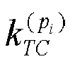
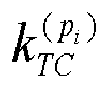
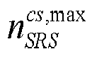
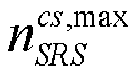
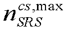
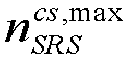
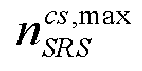
  • n SRS cs ⁇ 0,1 , ... , n SRS cs , max ⁇ 1 is a cyclic shift offset value configured by the network-side device through RRC signaling.
  • the initial CS in each table in this application is a cyclic shift offset value n SRS cs .
  • a corresponding comb position mapping method 2 is as follows: Eight ports for the first SRS are divided into two groups, comb positions mapped by ports in a same group are the same, and ports in different groups are mapped to different comb positions.
  • ports ⁇ 1001, 1003, 1005, 1007 ⁇ are one group and mapped to a same first comb position; and ports ⁇ 1000, 1002, 1004, 1006 ⁇ are one group and mapped to a same second comb position.
  • the first comb position and the second comb position are different.
  • a corresponding comb position mapping method 3 is as follows: The comb position mapped by the each port for the first SRS is related to the cyclic shift offset value; and for a specific cyclic shift offset value, eight ports for the first SRS are divided into two groups, comb positions mapped by ports in a same group are the same, and ports in different groups are mapped to different comb positions.
  • the FDM multiplexing mode between ports is related to the cyclic shift offset value n SRS cs .
  • the ports are grouped, and for a specific cyclic shift offset value, ports in different groups are mapped to different comb positions.
  • a CS mapping method 2 is as follows: The ports are grouped, ports in different groups correspond to different CSs, and ports in a same group use a same CS.
  • eight ports for the first SRS are divided into four groups, ports in a same group use a same CS, and ports in different groups use different CSs.
  • ports ⁇ 1000, 1001 ⁇ are one group and use a same CS; ports ⁇ 1002, 1003 ⁇ are one group and use a same CS; ports ⁇ 1004, 1005 ⁇ are one group and use a same CS; and ports ⁇ 1006, 1007 ⁇ are one group and use a same CS.
  • a corresponding comb position mapping method 4 is as follows: The ports are grouped, and ports in different groups are mapped to different comb positions.
  • eight ports for the first SRS are divided into two groups, comb positions mapped by ports in a same group are the same, and ports in different groups are mapped to different comb positions.
  • ports ⁇ 1001, 1003, 1005, 1007 ⁇ are mapped to a same first comb position; and ports ⁇ 1000, 1002, 1004, 1006 ⁇ are mapped to a same second comb position.
  • the first comb position and the second comb position are different.
  • This embodiment of this application provides the CS mapping method and comb position mapping method used for a case that the number of ports for SRSs is 8 and the comb structure size is 2, which can be used to improve the orthogonality of SRS reference signal transmission on the ports, and further improve the performance of uplink transmission.
  • a CS mapping method 3 is as follows: The ports are grouped, ports in different groups correspond to different CSs, and ports in a same group use a same CS.
  • ports for the first SRS are divided into four groups, ports in the same group use a same CS, and ports in different groups use different CSs, that is, ports ⁇ 1000, 1001 ⁇ use a same CS; ports ⁇ 1002, 1003 ⁇ use a same CS; ports ⁇ 1004, 1005 ⁇ use a same CS; and ports ⁇ 1006, 1007 ⁇ use a same CS.
  • a corresponding comb position mapping method 5 is as follows: Eight ports for the first SRS are divided into two groups, comb positions mapped by ports in a same group are the same, and ports in different groups are mapped to different comb positions, that is, ports ⁇ 1001, 1003, 1005, 1007 ⁇ are mapped to a same first comb position, and ports ⁇ 1000, 1002, 1004, 1006 ⁇ are mapped to a same second comb position. The first comb position and the second comb position are different.
  • a corresponding comb position mapping method 6 is as follows: The comb position mapped by the each port for the first SRS is related to the cyclic shift offset value. Ports are grouped, and for a specific cyclic shift offset value, ports in different groups are mapped to different comb positions.
  • a CS mapping method 4 is used as follows: The ports are grouped. Ports in different groups correspond to different CSs, and ports in a same group use a same CS. Eight ports for the first SRS are divided into two groups, ports in a same group use a same CS, and ports in different groups use different CSs.
  • ports ⁇ 1000, 1001, 1002, 1003 ⁇ use a same CS; and ports ⁇ 1004, 1005, 1006, 1007 ⁇ use a same CS.
  • a corresponding comb position mapping method 7 is as follows:
  • Eight ports for the first SRS are divided into four groups, comb positions mapped by ports in a same group are the same, and ports in different groups are mapped to different comb positions. That is, ports ⁇ 1000, 1004 ⁇ are mapped to a same first comb position, ports ⁇ 1001, 1005 ⁇ is mapped to a same second comb position, ports ⁇ 1002, 1006 ⁇ are mapped to a same third comb position, and ports ⁇ 1003, 1007 ⁇ are mapped to a same fourth comb position, where the first comb position, the second comb position, the third comb position, and the fourth comb position are different.
  • This embodiment of this application provides the CS mapping method and comb position mapping method used for a case that the number of ports for SRSs is 8 and the comb structure size is 4, which can be used to improve the orthogonality of SRS reference signal transmission on the ports, and further improve the performance of uplink transmission.
  • a CS mapping method 5 is as follows:
  • ports for the first SRS are divided into two groups, ports in the same group use a same CS, and ports in different groups use different CSs, that is, ports ⁇ 1000, 1001, 1002, 1003 ⁇ use a same CS, and ports ⁇ 1004, 1005, 1006, 1007 ⁇ use a same CS.
  • a corresponding comb position mapping method 8 is as follows:
  • Eight ports for the first SRS are divided into four groups, comb positions mapped by ports in a same group are the same, and ports in different groups are mapped to different comb positions. That is, ports ⁇ 1000, 1004 ⁇ are mapped to a same first comb position, ports ⁇ 1001, 1005 ⁇ is mapped to a same second comb position, ports ⁇ 1002, 1006 ⁇ are mapped to a same third comb position, and ports ⁇ 1003, 1007 ⁇ are mapped to a same fourth comb position, where the first comb position, the second comb position, the third comb position, and the fourth comb position are different.
  • a corresponding comb position mapping method 9 is as follows: Different ports for the first SRS are mapped to different comb positions.
  • mapping different ports for the first SRS to different comb positions can also be understood as grouping ports, with each port in one group, and ports in different groups are mapped to different comb positions, that is, different ports are mapped to different comb positions.
  • This embodiment of this application provides the CS mapping method and comb position mapping method used for a case that the number of ports for SRSs is 8 and the comb structure size is 8, which can be used to improve the orthogonality of SRS reference signal transmission on the ports, and further improve the performance of uplink transmission.
  • a CS mapping method 7 is as follows: Different ports for the first SRS use different CSs, and different ports correspond to different CSs through rounding down.
  • a corresponding comb position mapping method 10 is as follows: Six ports for the first SRS are divided into two groups, comb positions mapped by ports in a same group are the same, and ports in different groups are mapped to different comb positions.
  • ports ⁇ 1000, 1002, 1003, 1005 ⁇ are one group and mapped to a same first comb position; and ports ⁇ 1001, 1004 ⁇ are one group and mapped to a same second comb position.
  • the first comb position and the second comb position are different.
  • a port for the second SRS and ports ⁇ 1001, 1004 ⁇ for the first SRS are allowed to map to a same comb position.
  • the second SRS is one 2-port SRS; or the second SRS is one N-port SRS, where N>2, and two of the ports and the ports ⁇ 1001, 1004 ⁇ for the first SRS are mapped to a same comb position.
  • a cyclic shift offset value corresponding to the second SRS is equal to a value obtained by performing remainder calculation on a maximum cyclic shift offset value n SRS cs , max corresponding to the first SRS after adding 3 to a cyclic shift offset value corresponding to the first SRS.
  • a port for the second SRS and the ports ⁇ 1001, 1004 ⁇ for the first SRS are allowed to map to a same comb position.
  • the second SRS is one 2-port SRS; or the second SRS is one N-port SRS, where N>2, and two of the ports and the ports ⁇ 1001, 1004 ⁇ for the first SRS are mapped to a same comb position.
  • a cyclic shift offset value corresponding to the second SRS is equal to a value obtained by performing remainder calculation on a maximum cyclic shift offset value corresponding to the first SRS after adding 3 to a cyclic shift offset value corresponding to the first SRS.
  • ports ⁇ 1000, 1002, 1004 ⁇ are one group and mapped to a same first comb position; and ports ⁇ 1001, 1003, 1005 ⁇ are one group and mapped to a same second comb position.
  • the first comb position and the second comb position are different.
  • a CS mapping method 8 is as follows: Different ports for the first SRS use different CSs, and different ports correspond to different CSs through rounding up.
  • a corresponding comb position mapping method 11 is as follows: Six ports for the first SRS are divided into two groups, comb positions mapped by ports in a same group are the same, ports in different groups are mapped to different comb positions, and the number of ports in each group may be different.
  • ports ⁇ 1000, 1001, 1003, 1004 ⁇ are one group and mapped to a same first comb position; and ports ⁇ 1002, 1005 ⁇ are one group and mapped to a same second comb position.
  • the first comb position and the second comb position are different.
  • a port for the third SRS and ports ⁇ 1002, 1005 ⁇ for the first SRS are allowed to map to a same comb position.
  • the third SRS is one 2-port SRS; or the third SRS is one N-port SRS, where N>2, and two of the ports and the ports ⁇ 1002, 1005 ⁇ for the first SRS are mapped to a same comb position.
  • a cyclic shift offset value corresponding to the third SRS is equal to a value obtained by performing remainder calculation on a maximum cyclic shift offset value corresponding to the first SRS after adding 1 to a cyclic shift offset value corresponding to the first SRS.
  • a port for the third SRS and ports ⁇ 1002, 1005 ⁇ for the first SRS are allowed to map to a same comb position.
  • the third SRS is one 2-port SRS; or the third SRS is one N-port SRS, where N>2, and two of the ports and the ports ⁇ 1002, 1005 ⁇ for the first SRS are mapped to a same comb position.
  • a cyclic shift offset value corresponding to the third SRS is equal to a value obtained by performing remainder calculation on a maximum cyclic shift offset value corresponding to the first SRS after adding 1 to a cyclic shift offset value corresponding to the first SRS.
  • ports ⁇ 1000, 1002, 1004 ⁇ are one group and mapped to a same first comb position; and ports ⁇ 1001, 1003, 1005 ⁇ are one group and mapped to a same second comb position.
  • the first comb position and the second comb position are different.
  • a CS mapping method 9 is as follows: Different ports for the first SRS use different CSs, some ports are rounded up, and some ports are rounded down.
  • a corresponding comb position mapping method 12 is as follows: Six ports for the first SRS are divided into two groups, comb positions mapped by ports in a same group are the same, ports in different groups are mapped to different comb positions, and the number of ports in each group may be different.
  • ports ⁇ 1001, 1002, 1004, 1005 ⁇ are one group and mapped to a same first comb position; and ports ⁇ 1000, 1003 ⁇ are one group and mapped to a same second comb position.
  • the first comb position and the second comb position are different.
  • a port for the fourth SRS and ports ⁇ 1000, 1003 ⁇ for the first SRS are allowed to map to a same comb position.
  • the fourth SRS is one 2-port SRS; or the fourth SRS is one N-port SRS, where N>2, and two of the ports and the ports ⁇ 1000, 1003 ⁇ for the first SRS are mapped to a same comb position.
  • a cyclic shift offset value corresponding to the fourth SRS is equal to a value obtained by performing remainder calculation on a maximum cyclic shift offset value corresponding to the first SRS after adding 2 to a cyclic shift offset value corresponding to the first SRS.
  • a port for the fourth SRS and ports ⁇ 1000, 1003 ⁇ for the first SRS are allowed to map to a same comb position.
  • the fourth SRS is one 2-port SRS; or the fourth SRS is one N-port SRS, where N>2, and two of the ports and the ports ⁇ 1000, 1003 ⁇ for the first SRS are mapped to a same comb position.
  • a cyclic shift offset value corresponding to the fourth SRS is equal to a value obtained by performing remainder calculation on a maximum cyclic shift offset value corresponding to the first SRS after adding 2 to a cyclic shift offset value corresponding to the first SRS.
  • ports ⁇ 1000, 1002, 1004 ⁇ are one group and mapped to a same first comb position; and ports ⁇ 1001, 1003, 1005 ⁇ are one group and mapped to a same second comb position.
  • the first comb position and the second comb position are different.
  • a CS mapping method is as follows:
  • Different ports for the first SRS use different CSs, some ports are rounded up, and some ports are rounded down.
  • a corresponding comb position mapping method 13 is as follows: Six ports for the first SRS are divided into two groups, comb positions mapped by ports in a same group are the same, ports in different groups are mapped to different comb positions, and the number of ports in each group is the same.
  • ports ⁇ 1000, 1002, 1004 ⁇ are one group and mapped to a same first comb position; and ports ⁇ 1001, 1003, 1005 ⁇ are one group and mapped to a same second comb position.
  • the first comb position and the second comb position are different.
  • This embodiment of this application provides the CS mapping method and comb position mapping method used for a case that the number of ports for SRSs is 6 and the comb structure size is 2, which can be used to improve the orthogonality of SRS reference signal transmission on the ports, and further improve the performance of uplink transmission.
  • a CS mapping method 11 is as follows: Different ports for the first SRS use different CSs, that is, six ports use different CSs.
  • a corresponding comb position mapping method 14 is as follows: The comb position mapped by the each port for the first SRS is related to the cyclic shift offset value; and for a specific cyclic shift offset value, six ports for the first SRS are divided into two groups, comb positions mapped by ports in a same group are the same, and ports in different groups are mapped to different comb positions.
  • This embodiment of this application provides the CS mapping method and comb position mapping method used for a case that the number of ports for SRSs is 6 and the comb structure size is 4, which can be used to improve the orthogonality of SRS reference signal transmission on the ports, and further improve the performance of uplink transmission.
  • a CS mapping method 12 is as follows: Six ports for the first SRS are divided into two groups, ports in the same group use a same CS, and ports in different groups use different CSs, that is, ports ⁇ 1000, 1001, 1002 ⁇ are one group and use a same CS, and ports ⁇ 1003, 1004, 1005 ⁇ are one group and use a same CS.
  • a corresponding comb position mapping method 15 is as follows: Six ports for the first SRS are divided into three groups, comb positions mapped by ports in a same group are the same, and ports in different groups are mapped to different comb positions, that is, ports ⁇ 1000, 1003 ⁇ are mapped to a same first comb position, ports ⁇ 1000, 1004 ⁇ are mapped to a same second comb position, and ports ⁇ 1002, 1005 ⁇ are mapped to a same third comb position.
  • the first comb position, the second comb position, and the third comb position are different.
  • This embodiment of this application provides the CS mapping method and comb position mapping method used for a case that the number of ports for SRSs is 6 and the comb structure size is 6, which can be used to improve the orthogonality of SRS reference signal transmission on the ports, and further improve the performance of uplink transmission.
  • a CS mapping method 13 is as follows: Different ports for the first SRS use different CSs, that is, six ports use different CSs.
  • the corresponding comb position mapping method 16 is as follows: The comb position mapped by the each port for the first SRS is related to the cyclic shift offset value; and for a specific cyclic shift offset value, six ports for the first SRS are divided into two groups, comb positions mapped by ports in a same group are the same, and ports in different groups are mapped to different comb positions.
  • a CS mapping method 14 is as follows: Six ports for the first SRS are divided into three groups, ports in the same group use a same CS, and ports in different groups use different CSs, that is, ports ⁇ 1000, 1001 ⁇ are one group and use a same CS, ports ⁇ 1002, 1003 ⁇ are one group and use a same CS, and ports ⁇ 1004, 1005 ⁇ are one group and use a same CS.
  • the corresponding comb position mapping method 17 is as follows:
  • six ports for the first SRS are divided into two groups, comb positions mapped by ports in a same group are the same, and ports in different groups are mapped to different comb positions, that is, ports ⁇ 1001, 1003, 1005 ⁇ are mapped to a same first comb position, and ports ⁇ 1000, 1002, 1004 ⁇ are mapped to a same second comb position.
  • the first comb position and the second comb position are different.
  • a CS mapping method 15 is as follows: Six ports for the first SRS are divided into two groups, ports in the same group use a same CS, and ports in different groups use different CSs, that is, ports ⁇ 1000, 1001, 1002 ⁇ are one group and use a same CS, and ports ⁇ 1003, 1004, 1005 ⁇ are one group and use a same CS.
  • the corresponding comb position mapping method 18 is as follows: Six ports for the first SRS are divided into three groups, comb positions mapped by ports in a same group are the same, and ports in different groups are mapped to different comb positions, that is, ports ⁇ 1000, 1003 ⁇ are mapped to a same first comb position, ports ⁇ 1000, 1004 ⁇ are mapped to a same second comb position, and ports ⁇ 1002, 1005 ⁇ are mapped to a same third comb position.
  • the first comb position, the second comb position, and the third comb position are different.
  • This embodiment of this application provides the CS mapping method and comb position mapping method used for a case that the number of ports for SRSs is 6 and the comb structure size is 8, which can be used to improve the orthogonality of SRS reference signal transmission on the ports, and further improve the performance of uplink transmission.
  • the execution subject of the port mapping method for sounding reference signals provided in the embodiments of this application may be a port mapping apparatus for sounding reference signals.
  • the port mapping apparatus for sounding reference signals provided in the embodiments of this application is described by using the port mapping method for sounding reference signals being executed by the port mapping apparatus for sounding reference signals as an example.
  • FIG. 3 is a schematic flowchart of a port mapping apparatus for sounding reference signals according to an embodiment of this application. As shown in FIG. 3 , the apparatus 300 includes:
  • the CS corresponding to the each port for the first SRS is determined based on at least one of a cyclic shift offset value, a maximum cyclic shift offset value, a first parameter, a comb structure size, a port number, and the number of ports; and/or a comb position mapped by the each port for the first SRS is determined based on at least one of a comb offset value, a comb structure size, a cyclic shift offset value, a maximum cyclic shift offset value, a first parameter, and a port number.
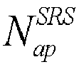
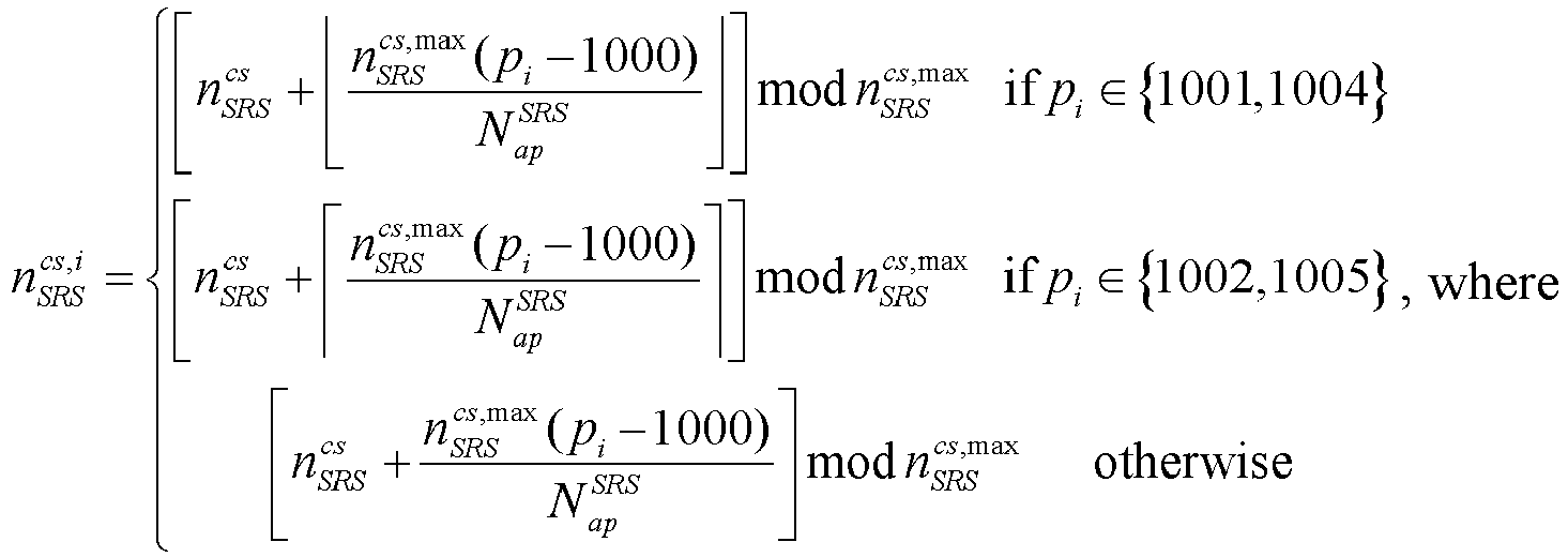
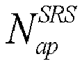
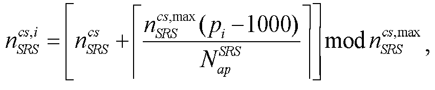
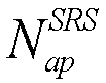
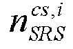
  • n SRS cs , i n SRS cs + n SRS cs , max p i ⁇ 1000 N ap SRS mod n SRS cs , max , where n SRS cs , i is a CS corresponding to port i, n SRS cs is the cyclic shift offset value, n SRS cs , max is the maximum cyclic shift offset value, p i is a port number, and N ap SRS is the number of ports.
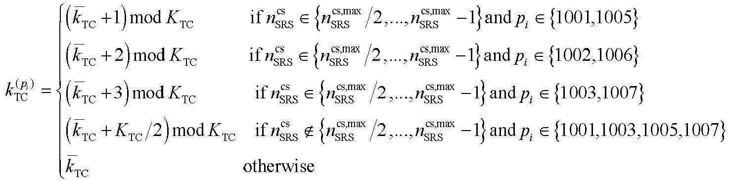
  • each port for the first SRS is mapped to a same comb position, and a comb position mapped by the each port for the first SRS is obtained through calculation by using the following formula:
  • eight ports for the first SRS are divided into two groups, comb positions mapped by ports in a same group are the same, and ports in different groups are mapped to different comb positions.
  • the comb position mapped by the each port for the first SRS is related to the cyclic shift offset value; and for a specific cyclic shift offset value, eight ports for the first SRS are divided into two groups, comb positions mapped by ports in a same group are the same, and ports in different groups are mapped to different comb positions.
  • the number of ports is 8 and the comb structure size is 2, eight ports for the first SRS are divided into four groups, ports in a same group uses a same CS, and ports in different groups use different CSs.
  • eight ports for the first SRS are divided into two groups, comb positions mapped by ports in a same group are the same, and ports in different groups are mapped to different comb positions.
  • the number of ports is 8 and the comb structure size is 4, eight ports for the first SRS are divided into four groups, ports in a same group uses a same CS, and ports in different groups use different CSs.
  • eight ports for the first SRS are divided into two groups, comb positions mapped by ports in a same group are the same, and ports in different groups are mapped to different comb positions.
  • the comb position mapped by the each port for the first SRS is related to the cyclic shift offset value.
  • the number of ports is 8 and the comb structure size is 4, eight ports for the first SRS are divided into two groups, ports in a same group uses a same CS, and ports in different groups use different CSs.
  • eight ports for the first SRS are divided into four groups, comb positions mapped by ports in a same group are the same, and ports in different groups are mapped to different comb positions.
  • the number of ports is 8 and the comb structure size is 8, eight ports for the first SRS are divided into two groups, ports in a same group uses a same CS, and ports in different groups use different CSs.
  • eight ports for the first SRS are divided into four groups, comb positions mapped by ports in a same group are the same, and ports in different groups are mapped to different comb positions.
  • all eight ports for the first SRS use a same CS.
  • different ports for the first SRS are mapped to different comb positions.
  • n SRS cs , i n SRS cs + ⁇ n SRS cs , max p i ⁇ 1000 N ap SRS ⁇ mod n SRS cs , max , where n SRS cs , i is a CS corresponding to port i, n SRS cs is the cyclic shift offset value, n SRS cs , max is the maximum cyclic shift offset value, p i is a port number, and N ap SRS is the number of ports.
  • ports for the first SRS are divided into two groups, comb positions mapped by ports in a same group are the same, and ports in different groups are mapped to different comb positions.
  • n SRS cs , i n SRS cs + ⁇ n SRS cs , max p i ⁇ 1000 N ap SRS ⁇ mod n SRS cs , max , where n SRS cs , i is a CS corresponding to port i, n SRS cs is the cyclic shift offset value, n SRS cs , max is the maximum cyclic shift offset value, p i is a port number, and N ap SRS is the number of ports.
  • ports for the first SRS are divided into two groups, comb positions mapped by ports in a same group are the same, and ports in different groups are mapped to different comb positions.
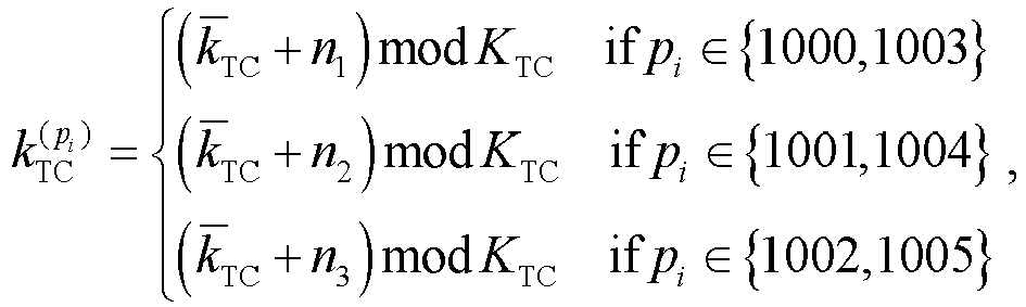
  • n SRS cs , i ⁇ n SRS cs + ⁇ n SRS cs , max p i ⁇ 1000 N ap SRS ⁇ mod n SRS cs , max if p i ⁇ 1001,1004 n SRS cs + ⁇ n SRS cs , max p i ⁇ 1000 N ap SRS ⁇ mod n SRS cs , max if p i ⁇ 1002,1005 n SRS cs + n SRS cs , max p i ⁇ 1000 N ap SRS mod n SRS cs , max otherwise , where n SRS cs , i is a CS corresponding
  • ports for the first SRS are divided into two groups, comb positions mapped by ports in a same group are the same, and ports in different groups are mapped to different comb positions.
  • n SRS cs , i ⁇ n SRS cs + ⁇ n SRS cs , max p i ⁇ 1000 N ap SRS ⁇ mod n SRS cs , max if p i ⁇ 1001 n SRS cs + ⁇ n SRS cs , max p i ⁇ 1000 N ap SRS ⁇ mod n SRS cs , max if p i ⁇ 1002 1004 1005 n SRS cs + n SRS cs , max p i ⁇ 1000 N ap SRS mod n SRS cs , max otherwise , where n SRS cs , i is a CS corresponding
  • ports for the first SRS are divided into two groups, comb positions mapped by ports in a same group are the same, and ports in different groups are mapped to different comb positions.
  • n SRS cs , i n SRS cs + n SRS cs , max p i ⁇ 1000 N ap SRS mod n SRS cs , max , where n SRS cs , i is a CS corresponding to port i, n SRS cs is the cyclic shift offset value, n SRS cs , max is the maximum cyclic shift offset value, p i is a port number, and N ap SRS is the number of ports.
  • the comb position mapped by the each port for the first SRS is related to the cyclic shift offset value; and for a specific cyclic shift offset value, six ports for the first SRS are divided into two groups, comb positions mapped by ports in a same group are the same, and ports in different groups are mapped to different comb positions.
  • the number of ports is 6 and the comb structure size is 6, six ports for the first SRS are divided into two groups, ports in a same group uses a same CS, and ports in different groups use different CSs.
  • six ports for the first SRS are divided into three groups, comb positions mapped by ports in a same group are the same, and ports in different groups are mapped to different comb positions.
  • n SRS cs , i n SRS cs + n SRS cs , max p i ⁇ 1000 N ap SRS mod n SRS cs , max , where n SRS cs , i is a CS corresponding to port i, n SRS cs is the cyclic shift offset value, n SRS cs , max is the maximum cyclic shift offset value, p i is a port number, and N ap SRS is the number of ports.
  • the comb position mapped by the each port for the first SRS is related to the cyclic shift offset value; and for a specific cyclic shift offset value, six ports for the first SRS are divided into two groups, comb positions mapped by ports in a same group are the same, and ports in different groups are mapped to different comb positions.
  • the number of ports is 6 and the comb structure size is 8
  • six ports for the first SRS are divided into three groups, ports in a same group uses a same CS, and ports in different groups use different CSs.
  • ports for the first SRS are divided into two groups, comb positions mapped by ports in a same group are the same, and ports in different groups are mapped to different comb positions.
  • the number of ports is 6 and the comb structure size is 8
  • six ports for the first SRS are divided into two groups, ports in a same group uses a same CS, and ports in different groups use different CSs.
  • six ports for the first SRS are divided into three groups, comb positions mapped by ports in a same group are the same, and ports in different groups are mapped to different comb positions.
  • This embodiment of this application provides a port mapping solution used for cases that different combs are configured for SRSs when the number of ports for SRSs is 6 and 8, which can improve the orthogonality of SRS reference signal transmission on each port, thereby improving performance of uplink transmission.
  • the port mapping apparatus for sounding reference signals in this embodiment of this application may be an electronic device, such as an electronic device with an operating system, or a component in the electronic device, such as an integrated circuit or a chip.
  • the electronic device may be a terminal or other devices than the terminal.
  • the terminal may include, but is not limited to, the types of the terminal 11 listed above, and other devices may be a server, a network attached storage (Network Attached Storage, NAS), and the like. This is not limited in the embodiments of this application.
  • the port mapping apparatus for sounding reference signals provided in this embodiment of this application is capable of implementing the processes implemented in the method embodiments in FIG. 2 , with the same technical effects achieved. To avoid repetition, details are not described herein again.
  • an embodiment of this application further provides a communication device 400, including a processor 401, a memory 402, and a program or instructions stored in the memory 402 and executable on the processor 401.
  • a communication device 400 including a processor 401, a memory 402, and a program or instructions stored in the memory 402 and executable on the processor 401.
  • the steps of the foregoing embodiments of the port mapping method for sounding reference signals are implemented, with the same technical effects achieved.
  • the communication device 400 is a network-side device and when the program or the instructions are executed by the processor 401, the steps of the foregoing embodiments of the port mapping method for sounding reference signals are implemented, with the same technical effects achieved. To avoid repetition, details are not described herein again.
  • An embodiment of this application further provides a terminal, including a processor and a communication interface, where the processor is configured to: in a case that the number of ports for a first sounding reference signal SRS is 6 or 8, determine a cyclic shift CS corresponding to each port for the first SRS and/or a comb (comb) position mapped by the each port for the first SRS; where a comb structure size of the first SRS is N, and N is 2, 4, 6, or 8.
  • the terminal embodiments correspond to the foregoing terminal-side method embodiments, and the implementation processes and implementations of the foregoing method embodiments can be applied to the terminal embodiments, with the same technical effects achieved.
  • FIG. 5 is a schematic diagram of a hardware structure of a terminal for implementing the embodiments of this application.
  • the terminal 500 includes but is not limited to at least part of components such as a radio frequency unit 501, a network module 502, an audio output unit 503, an input unit 504, a sensor 505, a display unit 506, a user input unit 507, an interface unit 508, a memory 509, and a processor 510.
  • components such as a radio frequency unit 501, a network module 502, an audio output unit 503, an input unit 504, a sensor 505, a display unit 506, a user input unit 507, an interface unit 508, a memory 509, and a processor 510.
  • the terminal 500 may further include a power supply (for example, a battery) supplying power to the components, and the power supply may be logically connected to the processor 510 through a power management system. In this way, functions such as charge management, discharge management, and power consumption management are implemented by using the power management system.
  • a power supply for example, a battery
  • functions such as charge management, discharge management, and power consumption management are implemented by using the power management system.
  • the structure of the terminal shown in FIG. 5 does not constitute any limitation on the terminal.
  • the terminal may include more or fewer components than shown in the figure, or a combination of some components, or the components disposed differently. Details are not described herein again.
  • the input unit 504 may include a graphics processing unit (Graphics Processing Unit, GPU) 5041 and a microphone 5042.
  • the graphics processing unit 5041 processes image data of a still picture or video obtained by an image capture apparatus (such as a camera) in a video capture mode or an image capture mode.
  • the display unit 506 may include a display panel 5061, and the display panel 5061 may be configured in a form of a liquid crystal display, an organic light-emitting diode, and the like.
  • the user input unit 507 may include at least one of a touch panel 5071 and other input devices 5072.
  • the touch panel 5071 is also referred to as a touchscreen.
  • the touch panel 5071 may include two parts: a touch detection apparatus and a touch controller.
  • the other input devices 5072 may include but are not limited to a physical keyboard, a function key (such as a volume control key or a power on/off key), a trackball, a mouse, a joystick, and the like. Details are not described herein.
  • the radio frequency unit 501 receives downlink data from a network-side device, and then sends the downlink data to the processor 510 for processing.
  • the radio frequency unit 501 may send uplink data to the network-side device.
  • the radio frequency unit 501 includes but is not limited to an antenna, an amplifier, a transceiver, a coupler, a low noise amplifier, a duplexer, and the like.
  • the memory 509 may be configured to store software programs or instructions and various data.
  • the memory 509 may include a first storage area for storing a program or instructions and a second storage area for storing data.
  • the first storage area may store an operating system, an application program or instruction required by at least one function (for example, a sound playback function or an image playback function), and the like.
  • the memory 509 may include a volatile memory or a non-volatile memory, or the memory 509 may include both a volatile memory and a non-volatile memory.
  • the non-volatile memory may be a read-only memory (Read-Only Memory, ROM), a programmable read only memory (Programmable ROM, PROM), an erasable programmable read-only memory (Erasable PROM, EPROM), and an electrically erasable programmable read-only memory (Electrically EPROM, EEPROM), or flash memory.
  • ROM Read-Only Memory
  • PROM programmable read only memory
  • Erasable PROM Erasable PROM
  • EPROM erasable programmable read-only memory
  • Electrically erasable programmable read-only memory Electrically erasable programmable read-only memory
  • the volatile memory can be a random access memory (Random Access Memory, RAM), a static random access memory (Static RAM, SRAM), a dynamic random access memory (Dynamic RAM, DRAM), a synchronous dynamic random access memory (Synchronous DRAM, SDRAM), a double data rate synchronous dynamic random access memory (Double Data Rate SDRAM, DDRSDRAM), an enhanced synchronous dynamic random access memory (Enhanced SDRAM, ESDRAM), a synchlink dynamic random access memory (Synch link DRAM, SLDRAM), and a direct rambus random access memory (Direct Rambus RAM, DRRAM).
  • RAM Random Access Memory
  • SRAM static random access memory
  • DRAM dynamic random access memory
  • DRAM synchronous dynamic random access memory
  • SDRAM double data rate synchronous dynamic random access memory
  • Enhanced SDRAM, ESDRAM enhanced synchronous dynamic random access memory
  • Synch link DRAM, SLDRAM synchlink dynamic random access memory
  • Direct Rambus RAM Direct Rambus RAM
  • the processor 510 may include one or more processing units.
  • an application processor and a modem processor may be integrated in the processor 510.
  • This application processor primarily processes operations involving an operating system, user interfaces, application programs, and the like.
  • the modem processor primarily processes radio communication signals, for example, being a baseband processor. It can be understood that the modem processor may alternatively be not integrated in the processor 510.
  • the processor 510 is configured to: in a case that the number of ports for a first sounding reference signal SRS is 6 or 8, determine a cyclic shift CS corresponding to each port for the first SRS and/or a comb (comb) position mapped by the each port for the first SRS; where a comb structure size of the first SRS is N, and N is 2, 4, 6, or 8.
  • the CS corresponding to the each port for the first SRS is determined based on at least one of a cyclic shift offset value, a maximum cyclic shift offset value, a first parameter, a comb structure size, a port number, and the number of ports; and/or a comb position mapped by the each port for the first SRS is determined based on at least one of a comb offset value, a comb structure size, a cyclic shift offset value, a maximum cyclic shift offset value, a first parameter, and a port number.
  • n SRS cs , i n SRS cs + n SRS cs , max p i ⁇ 1000 N ap SRS mod n SRS cs , max , where n SRS cs , i is a CS corresponding to port i, n SRS cs is the cyclic shift offset value, n SRS cs , max is the maximum cyclic shift offset value, p i is a port number, and N ap SRS is the number of ports.
  • eight ports for the first SRS are divided into two groups, comb positions mapped by ports in a same group are the same, and ports in different groups are mapped to different comb positions.
  • the comb position mapped by the each port for the first SRS is related to the cyclic shift offset value; and for a specific cyclic shift offset value, eight ports for the first SRS are divided into two groups, comb positions mapped by ports in a same group are the same, and ports in different groups are mapped to different comb positions.
  • the number of ports is 8 and the comb structure size is 2, eight ports for the first SRS are divided into four groups, ports in a same group uses a same CS, and ports in different groups use different CSs.
  • eight ports for the first SRS are divided into two groups, comb positions mapped by ports in a same group are the same, and ports in different groups are mapped to different comb positions.
  • the number of ports is 8 and the comb structure size is 4, eight ports for the first SRS are divided into four groups, ports in a same group uses a same CS, and ports in different groups use different CSs.
  • eight ports for the first SRS are divided into two groups, comb positions mapped by ports in a same group are the same, and ports in different groups are mapped to different comb positions.
  • the comb position mapped by the each port for the first SRS is related to the cyclic shift offset value.
  • the number of ports is 8 and the comb structure size is 4, eight ports for the first SRS are divided into two groups, ports in a same group uses a same CS, and ports in different groups use different CSs.
  • eight ports for the first SRS are divided into four groups, comb positions mapped by ports in a same group are the same, and ports in different groups are mapped to different comb positions.
  • the number of ports is 8 and the comb structure size is 8, eight ports for the first SRS are divided into two groups, ports in a same group uses a same CS, and ports in different groups use different CSs.
  • eight ports for the first SRS are divided into four groups, comb positions mapped by ports in a same group are the same, and ports in different groups are mapped to different comb positions.
  • all eight ports for the first SRS use a same CS.
  • different ports for the first SRS are mapped to different comb positions.
  • n SRS cs , i n SRS cs + ⁇ n SRS cs , max p i ⁇ 1000 N ap SRS ⁇ mod n SRS cs , max , where n SRS cs , i is a CS corresponding to port i, n SRS cs is the cyclic shift offset value, n SRS cs , max is the maximum cyclic shift offset value, p i is a port number, and N ap SRS is the number of ports.
  • ports for the first SRS are divided into two groups, comb positions mapped by ports in a same group are the same, and ports in different groups are mapped to different comb positions.
  • n SRS cs , i n SRS cs + ⁇ n SRS cs , max p i ⁇ 1000 N ap SRS ⁇ mod n SRS cs , max , where n SRS cs , i is a CS corresponding to port i, n SRS cs is the cyclic shift offset value, n SRS cs , max is the maximum cyclic shift offset value, p i is a port number, and N ap SRS is the number of ports.
  • ports for the first SRS are divided into two groups, comb positions mapped by ports in a same group are the same, and ports in different groups are mapped to different comb positions.
  • n SRS cs , i ⁇ n SRS cs + ⁇ n SRS cs , max p i ⁇ 1000 N ap SRS ⁇ mod n SRS cs , max if p i ⁇ 1001,1004 n SRS cs + ⁇ n SRS cs , max p i ⁇ 1000 N ap SRS ⁇ mod n SRS cs , max if p i ⁇ 1002,1005 n SRS cs + n SRS cs , max p i ⁇ 1000 N ap SRS mod n SRS cs , max otherwise , where n SRS cs , i is a CS corresponding
  • ports for the first SRS are divided into two groups, comb positions mapped by ports in a same group are the same, and ports in different groups are mapped to different comb positions.
  • n SRS cs , i ⁇ n SRS cs + ⁇ n SRS cs , max p i ⁇ 1000 N ap SRS ⁇ mod n SRS cs , max if p i ⁇ 1001 n SRS cs + ⁇ n SRS cs , max p i ⁇ 1000 N ap SRS ⁇ mod n SRS cs , max if p i ⁇ 1002 1004 1005 n SRS cs + n SRS cs , max p i ⁇ 1000 N ap SRS mod n SRS cs , max otherwise , where n SRS cs , i is a CS corresponding
  • ports for the first SRS are divided into two groups, comb positions mapped by ports in a same group are the same, and ports in different groups are mapped to different comb positions.
  • n SRS cs , i n SRS cs + n SRS cs , max p i ⁇ 1000 N ap SRS mod n SRS cs , max , where n SRS cs , i is a CS corresponding to port i, n SRS cs is the cyclic shift offset value, n SRS cs , max is the maximum cyclic shift offset value, p i is a port number, and N ap SRS is the number of ports.
  • the comb position mapped by the each port for the first SRS is related to the cyclic shift offset value; and for a specific cyclic shift offset value, six ports for the first SRS are divided into two groups, comb positions mapped by ports in a same group are the same, and ports in different groups are mapped to different comb positions.
  • the number of ports is 6 and the comb structure size is 6, six ports for the first SRS are divided into two groups, ports in a same group uses a same CS, and ports in different groups use different CSs.
  • six ports for the first SRS are divided into three groups, comb positions mapped by ports in a same group are the same, and ports in different groups are mapped to different comb positions.
  • n SRS cs , i n SRS cs + n SRS cs , max p i ⁇ 1000 N ap SRS mod n SRS cs , max , where n SRS cs , i is a CS corresponding to port i, n SRS cs is the cyclic shift offset value, n SRS cs , max is the maximum cyclic shift offset value, p i is a port number, and N ap SRS is the number of ports.
  • the comb position mapped by the each port for the first SRS is related to the cyclic shift offset value; and for a specific cyclic shift offset value, six ports for the first SRS are divided into two groups, comb positions mapped by ports in a same group are the same, and ports in different groups are mapped to different comb positions.
  • the number of ports is 6 and the comb structure size is 8
  • six ports for the first SRS are divided into three groups, ports in a same group uses a same CS, and ports in different groups use different CSs.
  • ports for the first SRS are divided into two groups, comb positions mapped by ports in a same group are the same, and ports in different groups are mapped to different comb positions.
  • the number of ports is 6 and the comb structure size is 8
  • six ports for the first SRS are divided into two groups, ports in a same group uses a same CS, and ports in different groups use different CSs.
  • six ports for the first SRS are divided into three groups, comb positions mapped by ports in a same group are the same, and ports in different groups are mapped to different comb positions.
  • This embodiment of this application provides a port mapping solution used for cases that different combs are configured for SRSs when the number of ports for SRSs is 6 and 8, which can improve the orthogonality of SRS reference signal transmission on each port, thereby improving performance of uplink transmission.
  • An embodiment of this application further provides a readable storage medium, where a program or instructions are stored in the readable storage medium.
  • a program or instructions are stored in the readable storage medium.
  • the processor is a processor in the terminal described in the foregoing embodiments.
  • the readable storage medium includes a computer-readable storage medium, for example, a computer read only memory ROM, a random access memory RAM, a magnetic disk, or an optical disc.
  • An embodiment of this application further provides a chip, where the chip includes a processor and a communication interface.
  • the communication interface is coupled to the processor, and the processor is configured to run a program or an instruction to implement the processes of the foregoing embodiment of the port mapping method for sounding reference signals, with the same technical effects achieved. To avoid repetition, details are not described herein again.
  • the chip mentioned in the embodiments of this application may also be referred to as a system-level chip, a system chip, a chip system, a system-on-chip, or the like.
  • An embodiment of this application further provides a computer program/program product, where the computer program/program product is stored in a storage medium, and when being executed by at least one processor, the computer program/program product is configured to implement the processes of the foregoing embodiments of the port mapping method for sounding reference signals, with the same technical effects achieved. To avoid repetition, details are not repeated herein.
  • An embodiment of this application further provides a communications system, which includes a terminal and a network-side device, where the terminal can be configured to execute the steps of the port mapping method for sounding reference signals.
  • the computer software product is stored in a storage medium (such as a ROM/RAM, a magnetic disk, or an optical disc), and includes several instructions for instructing a terminal (which may be a mobile phone, a computer, a server, an air conditioner, a network device, or the like) to perform the methods described in the embodiments of this application.
  • a storage medium such as a ROM/RAM, a magnetic disk, or an optical disc
  • a terminal which may be a mobile phone, a computer, a server, an air conditioner, a network device, or the like

Landscapes

  • Engineering & Computer Science (AREA)
  • Signal Processing (AREA)
  • Computer Networks & Wireless Communication (AREA)
  • Mobile Radio Communication Systems (AREA)
  • Cable Transmission Systems, Equalization Of Radio And Reduction Of Echo (AREA)
  • Liquid Crystal (AREA)

Abstract

This application discloses a port mapping method for sounding reference signals and a terminal, pertaining to the field of communication technologies. The port mapping method for sounding reference signals in embodiments of this application includes: in a case that a number of ports for a first sounding reference signal SRS is 6 or 8, determining, by a terminal, a cyclic shift CS corresponding to each port for the first SRS and/or a comb position mapped by the each port for the first SRS; where a comb structure size of the first SRS is N, and N is 2, 4, 6, or 8.

Description

    CROSS-REFERENCE TO RELATED APPLICATION
  • This application claims priority to Chinese Patent Application No. 202210016659.0, filed on January 7, 2022 , and entitled "PORT MAPPING METHOD FOR SOUNDING REFERENCE SIGNALS AND TERMINAL", which is incorporated herein by reference in its entirety.
  • TECHNICAL FIELD
  • This application pertains to the field of communications technologies, and in particular, relates to a port mapping method for sounding reference signals and a terminal.
  • BACKGROUND
  • In an NR system, sounding reference signals (Sounding Reference Signal, SRS) can be used for beam management (beam management), codebook (codebook)-based transmission, non-codebook (non-codebook)-based transmission, and antenna switching (antenna switching) transmission. A terminal can obtain a plurality of SRS resource sets through higher-layer signaling, and configuration for each SRS resource set includes configurations of its usage, periodic characteristics, or the like.
  • In Release-15/16, SRS resources can occupy the last 6 symbols in one slot, and configuration can be made through higher-layer signaling to occupy 1/2/4 symbol for SRS transmission, and supports a comb-like structure such as comb-2 and comb-4 in frequency domain. Release-17 is enhanced on the basis of Release-15/16. In one slot, a starting symbol position of SRS resources may be any symbol in one slot. A comb-8 structure is also supported.
  • The existing NR protocol supports only the number of SRS ports being 1, 2, and 4. To further improve the performance of uplink transmission, it is necessary to support a larger quantity of SRS ports, for example, the number of SRS ports is 6 and 8. Because orthogonality between different SRS ports needs to be guaranteed as much as possible, existing SRS port mapping modes cannot be fully applied to a case with the number of SRS ports being 6 and 8.
  • SUMMARY
  • Embodiments of this application provide a port mapping method for sounding reference signals and a terminal, which can resolve the problem of port mapping for SRSs with the number of ports being 6 and 8.
  • According to a first aspect, a port mapping method for sounding reference signals is provided, where the method includes:
    • in a case that the number of ports for a first sounding reference signal SRS is 6 or 8, determining, by a terminal, a cyclic shift CS corresponding to each port for the first SRS and/or a comb (comb) position mapped by the each port for the first SRS; where
    • a comb structure size of the first SRS is N, and N is 2, 4, 6, or 8.
  • According to a second aspect, a port mapping apparatus for sounding reference signals is provided, including: a first determining unit, configured to: in a case that the number of ports for a first sounding reference signal SRS is 6 or 8, determine, for a terminal, a cyclic shift CS corresponding to each port for the first SRS and/or a comb (comb) position mapped by the each port for the first SRS; where
    a comb structure size of the first SRS is N, and N is 2, 4, 6, or 8.
  • According to a third aspect, a terminal is provided, where the terminal includes a processor and a memory, and a program or instructions executable on the processor are stored in the memory. When the program or the instructions are executed by the processor, the steps of the method according to the first aspect are implemented.
  • According to a fourth aspect, a terminal is provided, including a processor and a communication interface, where the processor is configured to: in a case that the number of ports for a first sounding reference signal SRS is 6 or 8, determine a cyclic shift CS corresponding to each port for the first SRS and/or a comb (comb) position mapped by the each port for the first SRS; where a comb structure size of the first SRS is N, and N is 2, 4, 6, or 8.
  • According to a fifth aspect, a readable storage medium is provided, where a program or instructions are stored in the readable storage medium, and when the program or the instructions are executed by a processor, the steps of the method according to the first aspect are implemented.
  • According to a sixth aspect, a chip is provided, where the chip includes a processor and a communication interface, the communication interface is coupled to the processor, and the processor is configured to run a program or instructions to implement the method according to the first aspect.
  • According to a seventh aspect, a computer program/program product is provided, where the computer program/program product is stored in a storage medium, and the computer program/program product is executed by at least one processor to implement the steps of the port mapping method for sounding reference signals according to the first aspect.
  • The embodiments of this application provide a port mapping solution used for cases that different combs are configured for SRSs when the number of ports for SRSs is 6 and 8, which can improve the orthogonality of SRS reference signal transmission on each port, thereby improving performance of uplink transmission.
  • BRIEF DESCRIPTION OF DRAWINGS
    • FIG. 1 is a block diagram of a wireless communications system to which the embodiments of this application are applicable;
    • FIG. 2 is a schematic flowchart of a port mapping method for sounding reference signals according to an embodiment of this application;
    • FIG. 3 is a schematic structural diagram of a port mapping apparatus for sounding reference signals according to an embodiment of this application;
    • FIG. 4 is a schematic structural diagram of a communication device according to an embodiment of this application; and
    • FIG. 5 is a schematic diagram of a hardware structure of a terminal for implementing the embodiments of this application.
    DESCRIPTION OF EMBODIMENTS
  • The following clearly describes the technical solutions in the embodiments of this application with reference to the accompanying drawings in the embodiments of this application. Apparently, the described embodiments are only some rather than all of the embodiments of this application. All other embodiments obtained by persons of ordinary skill in the art based on the embodiments of this application shall fall within the protection scope of this application.
  • In the specification and claims of this application, the terms such as "first" and "second" are intended to distinguish between similar objects but do not necessarily indicate a specific order or sequence. It should be understood that the terms used in this way is interchangeable in appropriate circumstances so that the embodiments of this application can be implemented in other orders than the order illustrated or described herein, and "first" and "second" are usually for distinguishing same-type objects but not limiting the number of objects, for example, there may be one or more first objects. In addition, "and/or" in this specification and claims indicates at least one of connected objects, and the symbol "/" generally indicates that the associated objects are in an "or" relationship.
  • It should be noted that technologies described in the embodiments of this application are not limited to a long term evolution (Long Term Evolution, LTE)/LTE-advanced (LTE-Advanced, LTE-A) system, and may also be used in various wireless communications systems, such as code division multiple access (Code Division Multiple Access, CDMA), time division multiple access (Time Division Multiple Access, TDMA), frequency division multiple access (Frequency Division Multiple Access, FDMA), orthogonal frequency division multiple access (Orthogonal Frequency Division Multiple Access, OFDMA), single-carrier frequency-division multiple access (Single-carrier Frequency Division Multiple Access, SC-FDMA), and other systems. The terms "system" and "network" in the embodiments of this application are usually used interchangeably. Techniques described herein may be used in the aforementioned systems and radio technologies, and may also be used in other systems and radio technologies. In the following descriptions, a new radio (New Radio, NR) system is described for an illustration purpose, and NR terms are used in most of the following descriptions, although these technologies may also be applied to other applications than an NR system application, for example, the 6th generation (6th Generation, 6G) communications system.
  • FIG. 1 is a block diagram of a wireless communications system to which the embodiments of this application are applicable. The wireless communications system includes a terminal 11 and a network-side device 12. The terminal 11 may be a terminal-side device, such as a mobile phone, a tablet computer (Tablet Personal Computer), a laptop computer (Laptop Computer) or a notebook computer, a personal digital assistant (Personal Digital Assistant, PDA), a palmtop computer, a netbook, an ultra-mobile personal computer (ultra-mobile personal computer, UMPC), a mobile Internet device (Mobile Internet Device, MID), an augmented reality (augmented reality, AR)/virtual reality (virtual reality, VR) device, a robot, a wearable device (Wearable Device), vehicle user equipment (VUE), pedestrian user equipment (PUE), a smart home device (a home device with wireless communication function, such as a refrigerator, a television, a washing machine, or a furniture), a game console, a personal computer (personal computer, PC), a teller machine, a self-service machine, or the like. The wearable device includes: a smart watch, a wrist band, smart earphones, smart glasses, smart jewelry (smart bracelet, smart wristband, smart ring, smart necklace, smart anklet, smart ankle bracelet, or the like), smart wristband, smart clothing, and the like. It should be noted that a specific type of the terminal 11 is not limited in the embodiments of this application. The network-side device 12 may include an access network device or a core network device, where the access network device 12 may also be referred to as a radio access network device, a radio access network (Radio Access Network, RAN), a radio access network function, or a radio access network unit. The access network device 12 may include a base station, a WLAN access point a Wi-Fi node, or the like. The base station may be referred to as a NodeB, an evolved NodeB (eNB), an access point, a base transceiver station (Base Transceiver Station, BTS), a radio base station, a radio transceiver, a basic service set (Basic Service Set, BSS), an extended service set (Extended Service Set, ESS), a home NodeB, a home evolved NodeB, a WLAN access point, a Wi-Fi node, a transmission and reception point (Transmitting Receiving Point, TRP), or another appropriate term in the art. Provided that a same technical effect is achieved, the base station is not limited to a specific technical term. It should be noted that in the embodiments of this application, the base station in the NR system is merely used as an example, and a specific type of the base station is not limited. The core network device may include but is not limited to at least one of the following: a core network node, a core network function, a mobility management entity (Mobility Management Entity, MME), an access mobility management function (Access and Mobility Management Function, AMF), a session management function (Session Management Function, SMF), a user plane function (User Plane Function, UPF), a policy control function (Policy Control Function, PCF), a policy and charging rules function (Policy and Charging Rules Function, PCRF), an edge application service discovery function (Edge Application Server Discovery Function, EASDF), a unified data management (Unified Data Management, UDM), a unified data repository (Unified Data Repository, UDR), a home subscriber server (Home Subscriber Server, HSS), a centralized network configuration (Centralized network configuration, CNC), a network storage function (Network Repository Function, NRF), a network exposure function (Network Exposure Function, NEF), a local NEF (Local NEF, or L-NEF), a binding support function (Binding Support Function, BSF), an application Function (Application Function, AF), and the like. It should be noted that, in the embodiments of this application, a core network device in an NR system is used as an example for description, and a specific type of the core network device is not limited.
  • The following describes in detail a port mapping method for sounding reference signals provided in the embodiments of this application by using some embodiments and application scenarios thereof with reference to the accompanying drawings.
  • FIG. 2 is a schematic flowchart of a port mapping method for sounding reference signals according to an embodiment of this application. As shown in FIG. 2, the method includes:
  • Step 200: In a case that the number of ports for a first sounding reference signal SRS is 6 or 8, a terminal determines a cyclic shift (cyclic shift, CS) corresponding to the each port for the first SRS and/or a comb (comb) position mapped by the each port for the first SRS; where
    a comb structure size of the first SRS is N, and N is 2, 4, 6, or 8.
  • It should be noted that the comb position can be understood as a subcarrier position mapped by an SRS in frequency domain.
  • This embodiment of this application provides a port mapping solution used for cases that different combs are configured for SRSs when the number of ports for SRSs is 6 and 8, which can improve the orthogonality of SRS reference signal transmission on each port. Optionally, the CS corresponding to the each port for the first SRS is determined based on at least one of a cyclic shift offset value, a maximum cyclic shift offset value, a first parameter, a comb structure size, a port number, and the number of ports; and/or
    a comb position mapped by the each port for the first SRS is determined based on at least one of a comb offset value, the comb structure size, the cyclic shift offset value, the maximum cyclic shift offset value, the first parameter, and the port number.
  • The first parameter is a value agreed by default between a network-side device and the terminal and/or a value indicated by the network-side device and/or a value reported by the terminal.
  • This embodiment of this application provides a method for determining CSs corresponding to ports for SRSs and comb positions mapped by the ports, which can improve the orthogonality of SRS reference signal transmission on the ports, thereby improving the performance of uplink transmission.
  • Optionally, in a case that the number of ports is 8 and the comb structure size is 2, a CS mapping method 1 is as follows:
    Different ports for the first SRS correspond to different CSs, that is, eight ports use different CSs; where
    a CS corresponding to the each port for the first SRS is obtained through calculation by using the following formula: n SRS cs , i = n SRS cs + n SRS cs , max p i 1000 N ap SRS mod n SRS cs , max ,
    Figure imgb0001
    where
    n SRS cs , i
    Figure imgb0002
    is a CS corresponding to port i, n SRS cs
    Figure imgb0003
    is the cyclic shift offset value, n SRS cs , max
    Figure imgb0004
    is the maximum cyclic shift offset value, pi is a port number, and N ap SRS
    Figure imgb0005
    is the number of ports, where p i = 1000 + i
    Figure imgb0006
  • It should be noted that n SRS cs 0,1 , , n SRS cs , max 1
    Figure imgb0007
    is a cyclic shift offset value configured by the network-side device through RRC signaling. The maximum cyclic shift offset value, namely n SRS cs , max
    Figure imgb0008
    , is n SRS cs , max = 6
    Figure imgb0009
    if K TC =8, n SRS cs , max = 12
    Figure imgb0010
    if K TC=4, and n SRS cs , max = 8
    Figure imgb0011
    if K TC = 2, where K TC is the comb structure size.
  • For the CS mapping method 1, specific CS values corresponding to ports are shown in Table 1. Table 1 Specific CS values corresponding to ports
    1000 1001 1002 1003 1004 1005 1006 1007
    Initial CS 0 0 1 2 3 4 5 6 7
    Initial CS 1 1 2 3 4 5 6 7 0
    Initial CS 2 2 3 4 5 6 7 0 1
    Initial CS 3 3 4 5 6 7 0 1 2
    Initial CS 4 4 5 6 7 0 1 2 3
    Initial CS 5 5 6 7 0 1 2 3 4
    Initial CS 6 6 7 0 1 2 3 4 5
    Initial CS 7 7 0 1 2 3 4 5 6
  • It should be noted that the initial CS in each table in this application is a cyclic shift offset value n SRS cs
    Figure imgb0012
    .
  • Optionally, in a case that the number of ports is 8, the comb structure size is 2, and the CS mapping method 1 is used, a corresponding comb position mapping method 1 is as follows:
    The each port for the first SRS is mapped to a same comb position, and a comb position mapped by the each port for the first SRS is obtained through calculation by using the following formula: k TC p i = k TC ,
    Figure imgb0013
    where
    k TC p i
    Figure imgb0014
    is a comb position mapped by port i, and kTC is the comb offset value.
  • It should be noted that in the embodiments of this application, the comb offset value k TC ∈ {0,1,...,K TC -1} is configured by the network-side device through RRC signaling, where K TC is a comb structure size, for example, for comb-4, K TC =4 .
  • Optionally, in a case that the number of ports is 8, the comb structure size is 2, and the CS mapping method 1 is used, a corresponding comb position mapping method 2 is as follows:
    Eight ports for the first SRS are divided into two groups, comb positions mapped by ports in a same group are the same, and ports in different groups are mapped to different comb positions.
  • That is, ports {1001, 1003, 1005, 1007} are one group and mapped to a same first comb position; and ports {1000, 1002, 1004, 1006} are one group and mapped to a same second comb position. The first comb position and the second comb position are different.
  • A comb position mapped by the each port for the first SRS is obtained through calculation by using the following formula: k TC p i = { k TC + K TC / 2 mod K TC if p i 1001 1003 1005 1007 k TC otherwise
    Figure imgb0015
    or k TC p i = { k TC + K TC / 2 mod K TC if p i 1000 1002 1004 1006 k TC otherwise ,
    Figure imgb0016
    where
    k TC p i
    Figure imgb0017
    is a comb position mapped by port i, kTC is the comb offset value, and K TC is the comb structure size.
  • Optionally, in a case that the number of ports is 8, the comb structure size is 2, and the CS mapping method 1 is used, a corresponding comb position mapping method 3 is as follows:
    The comb position mapped by the each port for the first SRS is related to the cyclic shift offset value; and for a specific cyclic shift offset value, eight ports for the first SRS are divided into two groups, comb positions mapped by ports in a same group are the same, and ports in different groups are mapped to different comb positions.
  • That is, the FDM multiplexing mode between ports is related to the cyclic shift offset value n SRS cs
    Figure imgb0018
    . The ports are grouped, and for a specific cyclic shift offset value, ports in different groups are mapped to different comb positions.
  • A comb position mapped by the each port for the first SRS is obtained through calculation by using the following formula: k TC p i = { k TC + K TC / 2 mod K TC if n SRS cs n SRS cs , max / 2 , , n SRS cs , max 1 and p i 1001 1003 1005 1007 k TC otherwise
    Figure imgb0019
    or k TC p i = { k TC + K TC / 2 mod K TC if n SRS cs n SRS cs , max / 2 , , n SRS cs , max 1 and p i 1000 1002 1004 1006 k TC otherwise ,
    Figure imgb0020
    where
    k TC p i
    Figure imgb0021
    is a comb position mapped by port i, kTC is the comb offset value, and K TC is the comb structure size.
  • Optionally, in a case that the number of ports is 8 and the comb structure size is 2, a CS mapping method 2 is as follows:
    The ports are grouped, ports in different groups correspond to different CSs, and ports in a same group use a same CS.
  • Optionally, eight ports for the first SRS are divided into four groups, ports in a same group use a same CS, and ports in different groups use different CSs.
  • That is, ports {1000, 1001} are one group and use a same CS; ports {1002, 1003} are one group and use a same CS; ports { 1004, 1005} are one group and use a same CS; and ports {1006, 1007} are one group and use a same CS.
  • A CS corresponding to the each port for the first SRS is obtained through calculation by using the following formula: n SRS cs , i = n SRS cs + n SRS cs , max p i 1000 / x x N ap SRS mod n SRS cs , max ,
    Figure imgb0022
    where
    n SRS cs , i
    Figure imgb0023
    is a CS corresponding to port i, n SRS cs
    Figure imgb0024
    is the cyclic shift offset value, n SRS cs , max
    Figure imgb0025
    is the maximum cyclic shift offset value, pi is a port number, N ap SRS
    Figure imgb0026
    is the number of ports, and x is the first parameter, where x is a value agreed by default between the network-side device and the terminal and/or a value indicated by the network-side device and/or a value reported by the terminal, and x=2.
  • For the CS mapping method 2, specific CS values corresponding to ports are shown in Table 2. Table 2 Specific CS values corresponding to ports
    1000 1001 1002 1003 1004 1005 1006 1007
    Initial CS 0 0 0 2 2 4 4 6 6
    Initial CS 1 1 1 3 3 5 5 7 7
    Initial CS 2 2 2 4 4 6 6 0 0
    Initial CS 3 3 3 5 5 7 7 1 1
    Initial CS 4 4 4 6 6 0 0 2 2
    Initial CS 5 5 5 7 7 1 1 3 3
    Initial CS 6 6 6 0 0 2 2 4 4
    Initial CS 7 7 7 1 1 3 3 5 5
  • Optionally, in a case that the number of ports is 8, the comb structure size is 2, and the CS mapping method 2 is used, a corresponding comb position mapping method 4 is as follows:
    The ports are grouped, and ports in different groups are mapped to different comb positions.
  • Optionally, eight ports for the first SRS are divided into two groups, comb positions mapped by ports in a same group are the same, and ports in different groups are mapped to different comb positions.
  • That is, ports {1001, 1003, 1005, 1007} are mapped to a same first comb position; and ports {1000, 1002, 1004, 1006} are mapped to a same second comb position. The first comb position and the second comb position are different.
  • A comb position mapped by the each port for the first SRS is obtained through calculation by using the following formula: k TC p i = { k TC + K TC / 2 mod K TC if p i 1001 1003 1005 1007 k TC otherwise
    Figure imgb0027
    or k TC p i = { k TC + K TC / 2 mod K TC if p i 1000 1002 1004 1006 k TC otherwise ,
    Figure imgb0028
    where
    k TC p i
    Figure imgb0029
    is a comb position mapped by port i, kTC is the comb offset value, and K TC is the comb structure size.
  • This embodiment of this application provides the CS mapping method and comb position mapping method used for a case that the number of ports for SRSs is 8 and the comb structure size is 2, which can be used to improve the orthogonality of SRS reference signal transmission on the ports, and further improve the performance of uplink transmission.
  • Optionally, in a case that the number of ports is 8 and the comb structure size is 4, a CS mapping method 3 is as follows:
    The ports are grouped, ports in different groups correspond to different CSs, and ports in a same group use a same CS.
  • Optionally, eight ports for the first SRS are divided into four groups, ports in the same group use a same CS, and ports in different groups use different CSs, that is, ports {1000, 1001} use a same CS; ports {1002, 1003 } use a same CS; ports {1004, 1005} use a same CS; and ports {1006, 1007} use a same CS.
  • A CS corresponding to the each port for the first SRS is obtained through calculation by using the following formula: n SRS cs , i = n SRS cs + n SRS cs , max p i 1000 / x x N ap SRS mod n SRS cs , max ,
    Figure imgb0030
    where
    n SRS cs , i
    Figure imgb0031
    is a CS corresponding to port i, n SRS cs
    Figure imgb0032
    is the cyclic shift offset value, n SRS cs , max
    Figure imgb0033
    is the maximum cyclic shift offset value, pi is a port number, N ap SRS
    Figure imgb0034
    is the number of ports, and x is the first parameter, where x is a value agreed by default between the network-side device and the terminal and/or a value indicated by the network-side device and/or a value reported by the terminal, and x=2.
  • For the CS mapping method 3, specific CS values corresponding to ports are shown in Table 3. Table 3 Specific CS values corresponding to ports
    1000 1001 1002 1003 1004 1005 1006 1007
    Initial CS 0 0 0 3 3 6 6 9 9
    Initial CS 1 1 1 4 4 7 7 10 10
    Initial CS 2 2 2 5 5 8 8 11 11
    Initial CS 3 3 3 6 6 9 9 0 0
    Initial CS 4 4 4 7 7 10 10 1 1
    Initial CS 5 5 5 8 8 11 11 2 2
    Initial CS 6 6 6 9 9 0 0 3 3
    Initial CS 7 7 7 10 10 1 1 4 4
    Initial CS 8 8 8 11 11 2 2 5 5
    Initial CS 9 9 9 0 0 3 3 6 6
    Initial CS 10 10 10 1 1 4 4 7 7
    Initial CS 11 11 11 2 2 5 5 8 8
  • Optionally, in a case that the number of ports is 8, the comb structure size is 4, and the CS mapping method 3 is used, a corresponding comb position mapping method 5 is as follows:
    Eight ports for the first SRS are divided into two groups, comb positions mapped by ports in a same group are the same, and ports in different groups are mapped to different comb positions, that is, ports {1001, 1003, 1005, 1007} are mapped to a same first comb position, and ports {1000, 1002, 1004, 1006} are mapped to a same second comb position. The first comb position and the second comb position are different.
  • A comb position mapped by the each port for the first SRS is obtained through calculation by using the following formula: k TC p i = { k TC + K TC / 2 mod K TC if p i 1001 1003 1005 1007 k TC otherwise
    Figure imgb0035
    or k TC p i = { k TC + K TC / 2 mod K TC if p i 1000 1002 1004 1006 k TC otherwise ,
    Figure imgb0036
    where
    k TC p i
    Figure imgb0037
    is a comb position mapped by port i, k TC is the comb offset value, and K TC is the comb structure size.
  • Optionally, in a case that the number of ports is 8, the comb structure size is 4, and the CS mapping method 3 is used, a corresponding comb position mapping method 6 is as follows:
    The comb position mapped by the each port for the first SRS is related to the cyclic shift offset value. Ports are grouped, and for a specific cyclic shift offset value, ports in different groups are mapped to different comb positions.
  • A comb position mapped by the each port for the first SRS is obtained through calculation by using the following formula: k TC p i = { k TC + 1 mod K TC if n SRS cs n SRS cs ,max / 2 , , n SRS cs ,max 1 and p i 1001,1005 k TC + 2 mod K TC if n SRS cs n SRS cs ,max / 2 , , n SRS cs ,max 1 and p i 1002,1006 k TC + 3 mod K TC if n SRS cs n SRS cs ,max / 2 , , n SRS cs ,max 1 and p i 1003,1007 k TC + K TC / 2 mod K TC if n SRS cs n SRS cs ,max / 2 , , n SRS cs ,max 1 and p i 1001 1003 1005 1007 k TC otherwise
    Figure imgb0038
    or k TC p i = { k TC + p i 1000 mod K TC mod K TC if n SRS cs n SRS cs ,max / 2 , , n SRS cs ,max 1 k TC + K TC / 2 mod K TC if n SRS cs n SRS cs ,max / 2 , , n SRS cs ,max 1 and p i 1001 1003 1005 1007 k TC otherwise
    Figure imgb0039
    or k TC p i = { k TC + p i 1000 mod 4 mod K TC if n SRS cs n SRS cs ,max / 2 , , n SRS cs ,max 1 k TC + K TC / 2 mod K TC if n SRS cs n SRS cs ,max / 2 , , n SRS cs ,max 1 and p i 1001 1003 1005 1007 k TC otherwise
    Figure imgb0040
    or k TC p i = { k TC + 1 mod K TC if n SRS cs n SRS cs ,max / 2 , , n SRS cs ,max 1 and p i 1002,1006 k TC + 2 mod K TC if n SRS cs n SRS cs ,max / 2 , , n SRS cs ,max 1 and p i 1001,1005 k TC + 3 mod K TC if n SRS cs n SRS cs ,max / 2 , , n SRS cs ,max 1 and p i 1003,1007 k TC + K TC / 2 mod K TC if n SRS cs n SRS cs ,max / 2 , , n SRS cs ,max 1 and p i 1001 1003 1005 1007 k TC otherwise
    Figure imgb0041
    or k TC p i = { k TC + K TC / 2 1 mod K TC if n SRS cs n SRS cs ,max / 2 , , n SRS cs ,max 1 and p i 1002,1006 k TC + K TC / 2 mod K TC if n SRS cs n SRS cs ,max / 2 , , n SRS cs ,max 1 and p i 1001,1005 k TC + K TC / 2 + 1 mod K TC if n SRS cs n SRS cs ,max / 2 , , n SRS cs ,max 1 and p i 1003,1007 k TC + K TC / 2 mod K TC if n SRS cs n SRS cs ,max / 2 , , n SRS cs ,max 1 and p i 1001 1003 1005 1007 k TC otherwise ,
    Figure imgb0042
    where
    k TC p i
    Figure imgb0043
    is a comb position mapped by port i, kTC is the comb offset value, and K TC is the comb structure size.
  • Optionally, in a case that the number of ports is 8 and the comb structure size is 4, a CS mapping method 4 is used as follows: The ports are grouped. Ports in different groups correspond to different CSs, and ports in a same group use a same CS. Eight ports for the first SRS are divided into two groups, ports in a same group use a same CS, and ports in different groups use different CSs.
  • That is, ports {1000, 1001, 1002, 1003} use a same CS; and ports {1004, 1005, 1006, 1007} use a same CS.
  • A CS corresponding to the each port for the first SRS is obtained through calculation by using the following formula: n SRS cs , i = n SRS cs + n SRS cs , max p i 1000 / x x N ap SRS mod n SRS cs , max
    Figure imgb0044
    or n SRS cs , i = n SRS cs + n SRS cs , max p i 1000 / K TC K TC N ap SRS mod n SRS cs , max ,
    Figure imgb0045
    where
    n SRS cs , i
    Figure imgb0046
    is a CS corresponding to port i, n SRS cs
    Figure imgb0047
    is the cyclic shift offset value, n SRS cs , max
    Figure imgb0048
    is the maximum cyclic shift offset value, pi is a port number, N ap SRS
    Figure imgb0049
    is the number of ports, x is the first parameter, x is a value agreed by default between the network-side device and the terminal and/or a value indicated by the network-side device and/or a value reported by the terminal, x=4, and K TC is the comb structure size.
  • For the CS mapping method 4, specific CS values corresponding to ports are shown in Table 4. Table 4 Specific CS values corresponding to ports
    1000 1001 1002 1003 1004 1005 1006 1007
    Initial CS 0 0 0 0 0 6 6 6 6
    Initial CS 1 1 1 1 1 7 7 7 7
    Initial CS 2 2 2 2 2 8 8 8 8
    Initial CS 3 3 3 3 3 9 9 9 9
    Initial CS 4 4 4 4 4 10 10 10 10
    Initial CS 5 5 5 5 5 11 11 11 11
    Initial CS 6 6 6 6 6 0 0 0 0
    Initial CS 7 7 7 7 7 1 1 1 1
    Initial CS 8 8 8 8 8 2 2 2 2
    Initial CS 9 9 9 9 9 3 3 3 3
    Initial CS 10 10 10 10 10 4 4 4 4
    Initial CS 11 11 11 11 11 5 5 5 5
  • Optionally, in a case that the number of ports is 8, the comb structure size is 4, and the CS mapping method 4 is used, a corresponding comb position mapping method 7 is as follows:
  • Eight ports for the first SRS are divided into four groups, comb positions mapped by ports in a same group are the same, and ports in different groups are mapped to different comb positions. That is, ports {1000, 1004} are mapped to a same first comb position, ports { 1001, 1005} is mapped to a same second comb position, ports {1002, 1006} are mapped to a same third comb position, and ports {1003, 1007} are mapped to a same fourth comb position, where the first comb position, the second comb position, the third comb position, and the fourth comb position are different.
  • A comb position mapped by the each port for the first SRS is obtained through calculation by using the following formula: k TC p i = { k TC if p i 1000,1004 k TC + 1 mod K TC if p i 1001,1005 k TC + 2 mod K TC if p i 1002,1006 k TC + 3 mod K TC if p i 1003,1007
    Figure imgb0050
    or k TC p i = k TC + p i 1000 mod K TC mod K TC
    Figure imgb0051
    or k TC p i = k TC + p i 1000 mod 4 mod K TC
    Figure imgb0052
    or k TC p i = k TC + p i 1000 mod x mod K TC ,
    Figure imgb0053
    where
    k TC p i
    Figure imgb0054
    is a comb position mapped by port i, k TC is the comb offset value, and x is the first parameter, where x is a value agreed by default between the network-side device and the terminal and/or a value indicated by the network-side device and/or a value reported by the terminal, and x=4.
  • This embodiment of this application provides the CS mapping method and comb position mapping method used for a case that the number of ports for SRSs is 8 and the comb structure size is 4, which can be used to improve the orthogonality of SRS reference signal transmission on the ports, and further improve the performance of uplink transmission.
  • Optionally, in a case that the number of ports is 8 and the comb structure size is 8, a CS mapping method 5 is as follows:
  • Eight ports for the first SRS are divided into two groups, ports in the same group use a same CS, and ports in different groups use different CSs, that is, ports {1000, 1001, 1002, 1003} use a same CS, and ports {1004, 1005, 1006, 1007} use a same CS.
  • A CS corresponding to the each port for the first SRS is obtained through calculation by using the following formula: n SRS cs , i = n SRS cs + n SRS cs , max p i 1000 / x x N ap SRS mod n SRS cs , max ,
    Figure imgb0055
    where
    n SRS cs , i
    Figure imgb0056
    is a CS corresponding to port i, n SRS cs
    Figure imgb0057
    is the cyclic shift offset value, n SRS cs , max
    Figure imgb0058
    is the maximum cyclic shift offset value, pi is a port number, N ap SRS
    Figure imgb0059
    is the number of ports, and x is the first parameter, where x is a value agreed by default between the network-side device and the terminal and/or a value indicated by the network-side device and/or a value reported by the terminal, and x=4.
  • For the CS mapping method 5, specific CS values corresponding to ports are shown in Table 5. Table 5 Specific CS values corresponding to ports
    1000 1001 1002 1003 1004 1005 1006 1007
    Initial CS 0 0 0 0 0 3 3 3 3
    Initial CS 1 1 1 1 1 4 4 4 4
    Initial CS 2 2 2 2 2 5 5 5 5
    Initial CS 3 3 3 3 3 0 0 0 0
    Initial CS 4 4 4 4 4 1 1 1 1
    Initial CS 5 5 5 5 5 2 2 2 2
  • Optionally, in a case that the number of ports is 8, the comb structure size is 8, and the CS mapping method 5 is used, a corresponding comb position mapping method 8 is as follows:
  • Eight ports for the first SRS are divided into four groups, comb positions mapped by ports in a same group are the same, and ports in different groups are mapped to different comb positions. That is, ports {1000, 1004} are mapped to a same first comb position, ports { 1001, 1005} is mapped to a same second comb position, ports {1002, 1006} are mapped to a same third comb position, and ports {1003, 1007} are mapped to a same fourth comb position, where the first comb position, the second comb position, the third comb position, and the fourth comb position are different.
  • A comb position mapped by the each port for the first SRS is obtained through calculation by using the following formula: k TC p i = { k TC if p i 1000,1004 k TC + 2 mod K TC if p i 1001,1005 k TC + 4 mod K TC if p i 1002,1006 k TC + 6 mod K TC if p i 1003,1007
    Figure imgb0060
    or k TC p i = k TC + 2 p i 1000 mod 4 mod K TC
    Figure imgb0061
    or k TC p i = k TC + 8 / x p i 1000 mod x mod K TC ,
    Figure imgb0062
    where
    k TC p i
    Figure imgb0063
    is a comb position mapped by port i, k TC is the comb offset value, and K TC is the comb structure size, and x is the first parameter, where x is a value agreed by default between the network-side device and the terminal and/or a value indicated by the network-side device and/or a value reported by the terminal, and x=4.
  • Optionally, in a case that the number of ports is 8 and the comb structure size is 8, a CS mapping method 6 is as follows:
    Eight ports for the first SRS all use a same CS, and a CS corresponding to the each port for the first SRS is obtained through calculation by using the following formula: n SRS cs , i = n SRS cs + n SRS cs , max p i 1000 / x x N ap SRS mod n SRS cs , max
    Figure imgb0064
    or n SRS cs , i = n SRS cs ,
    Figure imgb0065
    where
    n SRS cs , i
    Figure imgb0066
    is a CS corresponding to port i, n SRS cs
    Figure imgb0067
    is the cyclic shift offset value, n SRS cs , max
    Figure imgb0068
    is the maximum cyclic shift offset value, pi is a port number, N ap SRS
    Figure imgb0069
    is the number of ports, and x is the first parameter, where x is a value agreed by default between the network-side device and the terminal and/or a value indicated by the network-side device and/or a value reported by the terminal, and x =8.
  • For the CS mapping method 6, specific CS values corresponding to ports are shown in Table 6. Table 6 Specific CS values corresponding to ports
    1000 1001 1002 1003 1004 1005 1006 1007
    Initial CS 0 0 0 0 0 0 0 0 0
    Initial CS 1 1 1 1 1 1 1 1 1
    Initial CS 2 2 2 2 2 2 2 2 2
    Initial CS 3 3 3 3 3 3 3 3 3
    Initial CS 4 4 4 4 4 4 4 4 4
    Initial CS 5 5 5 5 5 5 5 5 5
  • Optionally, in a case that the number of ports is 8, the comb structure size is 8, and the CS mapping method 6 is used, a corresponding comb position mapping method 9 is as follows:
    Different ports for the first SRS are mapped to different comb positions.
  • It should be noted that mapping different ports for the first SRS to different comb positions can also be understood as grouping ports, with each port in one group, and ports in different groups are mapped to different comb positions, that is, different ports are mapped to different comb positions.
  • A comb position mapped by the each port for the first SRS is obtained through calculation by using the following formula: k TC p i = { k TC if p i 1000 k TC + 1 mod K TC if p i 1001 k TC + 2 mod K TC if p i 1002 k TC + 3 mod K TC if p i 1003 k TC + 4 mod K TC if p i 1004 k TC + 5 mod K TC if p i 1005 k TC + 6 mod K TC if p i 1006 k TC + 7 mod K TC if p i 1007
    Figure imgb0070
    or k TC p i = k TC + p i 1000 mod K TC
    Figure imgb0071
    or k TC p i = k TC + 8 / x p i 1000 mod x mod K TC ,
    Figure imgb0072
    where
    k TC p i
    Figure imgb0073
    is a comb position mapped by port i, k TC is the comb offset value, and K TC is the comb structure size.
  • This embodiment of this application provides the CS mapping method and comb position mapping method used for a case that the number of ports for SRSs is 8 and the comb structure size is 8, which can be used to improve the orthogonality of SRS reference signal transmission on the ports, and further improve the performance of uplink transmission.
  • Optionally, in a case that the number of ports is 6 and the comb structure size is 2, a CS mapping method 7 is as follows:
    Different ports for the first SRS use different CSs, and different ports correspond to different CSs through rounding down.
  • A CS corresponding to the each port for the first SRS is obtained through calculation by using the following formula: n SRS cs , i = n SRS cs + n SRS cs , max p i 1000 N ap SRS mod n SRS cs , max ,
    Figure imgb0074
    where
    n SRS cs , i
    Figure imgb0075
    is a CS corresponding to port i, n SRS cs
    Figure imgb0076
    is the cyclic shift offset value, n SRS cs , max
    Figure imgb0077
    is the maximum cyclic shift offset value, pi is a port number, and N ap SRS
    Figure imgb0078
    is the number of ports.
  • For the CS mapping method 7, specific CS values corresponding to ports are shown in Table 7. Table 7 Specific CS values corresponding to ports
    1000 1001 1002 1003 1004 1005
    Initial CS 0 0 1 2 4 5 6
    Initial CS 1 1 2 3 5 6 7
    Initial CS 2 2 3 4 6 7 0
    Initial CS 3 3 4 5 7 0 1
    Initial CS 4 4 5 6 0 1 2
    Initial CS 5 5 6 7 1 2 3
    Initial CS 6 6 7 0 2 3 4
    Initial CS 7 7 0 1 3 4 5
  • Optionally, in a case that the number of ports is 6, the comb structure size is 2, and the CS mapping method 7 is used, a corresponding comb position mapping method 10 is as follows:
    Six ports for the first SRS are divided into two groups, comb positions mapped by ports in a same group are the same, and ports in different groups are mapped to different comb positions.
  • In an implementation, ports {1000, 1002, 1003, 1005} are one group and mapped to a same first comb position; and ports { 1001, 1004} are one group and mapped to a same second comb position. The first comb position and the second comb position are different.
  • A comb position mapped by the each port for the first SRS is obtained through calculation by using the following formula: k TC p i = { k TC + K TC / 2 mod K TC if p i 1000 1002 1003 1005 k TC otherwise
    Figure imgb0079
  • In this case, a port for the second SRS and ports {1001, 1004} for the first SRS are allowed to map to a same comb position.
  • It should be noted that the second SRS is one 2-port SRS; or the second SRS is one N-port SRS, where N>2, and two of the ports and the ports {1001, 1004} for the first SRS are mapped to a same comb position.
  • A cyclic shift offset value corresponding to the second SRS is equal to a value obtained by performing remainder calculation on a maximum cyclic shift offset value n SRS cs , max
    Figure imgb0080
    corresponding to the first SRS after adding 3 to a cyclic shift offset value corresponding to the first SRS.
  • Alternatively, a comb position mapped by the each port for the first SRS is obtained through calculation by using the following formula: k TC p i = { k TC + K TC / 2 mod K TC if p i 1001,1004 k TC otherwise
    Figure imgb0081
  • In this case, a port for the second SRS and the ports {1001, 1004} for the first SRS are allowed to map to a same comb position. The second SRS is one 2-port SRS; or the second SRS is one N-port SRS, where N>2, and two of the ports and the ports { 1001, 1004} for the first SRS are mapped to a same comb position.
  • A cyclic shift offset value corresponding to the second SRS is equal to a value obtained by performing remainder calculation on a maximum cyclic shift offset value corresponding to the first SRS after adding 3 to a cyclic shift offset value corresponding to the first SRS.
  • In another implementation, ports {1000, 1002, 1004} are one group and mapped to a same first comb position; and ports {1001, 1003, 1005} are one group and mapped to a same second comb position. The first comb position and the second comb position are different. A comb position mapped by the each port for the first SRS is obtained through calculation by using the following formula: k TC p i = { k TC + K TC / 2 mod K TC if p i 1000 1002 1004 k TC otherwise
    Figure imgb0082
    or, k TC p i = { k TC + K TC / 2 mod K TC if p i 1001 1003 1005 k TC otherwise ,
    Figure imgb0083
    where
    k TC p i
    Figure imgb0084
    is a comb position mapped by port i, k TC is the comb offset value, and K TC is the comb structure size.
  • Optionally, in a case that the number of ports is 6 and the comb structure size is 2, a CS mapping method 8 is as follows:
    Different ports for the first SRS use different CSs, and different ports correspond to different CSs through rounding up.
  • A CS corresponding to the each port for the first SRS is obtained through calculation by using the following formula: n SRS cs , i = n SRS cs + n SRS cs , max p i 1000 N ap SRS mod n SRS cs , max ,
    Figure imgb0085
    where
    n SRS cs , i
    Figure imgb0086
    is a CS corresponding to port i, n SRS cs
    Figure imgb0087
    is the cyclic shift offset value, n SRS cs , max
    Figure imgb0088
    is the maximum cyclic shift offset value, pi is a port number, and N ap SRS
    Figure imgb0089
    is the number of ports.
  • For the CS mapping method 8, specific CS values corresponding to ports are shown in Table 8. Table 8 Specific CS values corresponding to ports
    1000 1001 1002 1003 1004 1005
    Initial CS 0 0 2 3 4 6 7
    Initial CS 1 1 3 4 5 7 0
    Initial CS 2 2 4 5 6 0 1
    Initial CS 3 3 5 6 7 1 2
    Initial CS 4 4 6 7 0 2 3
    Initial CS 5 5 7 0 1 3 4
    Initial CS 6 6 0 1 2 4 5
    Initial CS 7 7 1 2 3 5 6
  • Optionally, in a case that the number of ports is 6, the comb structure size is 2, and the CS mapping method 8 is used, a corresponding comb position mapping method 11 is as follows:
    Six ports for the first SRS are divided into two groups, comb positions mapped by ports in a same group are the same, ports in different groups are mapped to different comb positions, and the number of ports in each group may be different.
  • In an implementation, ports {1000, 1001, 1003, 1004} are one group and mapped to a same first comb position; and ports { 1002, 1005} are one group and mapped to a same second comb position. The first comb position and the second comb position are different.
  • A comb position mapped by the each port for the first SRS is obtained through calculation by using the following formula: k TC p i = { k TC + K TC / 2 mod K TC if p i 1000 1001 1003 1004 k TC otherwise
    Figure imgb0090
  • In this case, a port for the third SRS and ports { 1002, 1005} for the first SRS are allowed to map to a same comb position.
  • It should be noted that the third SRS is one 2-port SRS; or the third SRS is one N-port SRS, where N>2, and two of the ports and the ports {1002, 1005} for the first SRS are mapped to a same comb position.
  • A cyclic shift offset value corresponding to the third SRS is equal to a value obtained by performing remainder calculation on a maximum cyclic shift offset value corresponding to the first SRS after adding 1 to a cyclic shift offset value corresponding to the first SRS.
  • Alternatively, a comb position mapped by the each port for the first SRS is obtained through calculation by using the following formula: k TC p i = { k TC + K TC / 2 mod K TC if p i 1002,1005 k TC otherwise
    Figure imgb0091
  • In this case, a port for the third SRS and ports { 1002, 1005} for the first SRS are allowed to map to a same comb position.
  • It should be noted that the third SRS is one 2-port SRS; or the third SRS is one N-port SRS, where N>2, and two of the ports and the ports {1002, 1005} for the first SRS are mapped to a same comb position.
  • A cyclic shift offset value corresponding to the third SRS is equal to a value obtained by performing remainder calculation on a maximum cyclic shift offset value corresponding to the first SRS after adding 1 to a cyclic shift offset value corresponding to the first SRS.
  • In another implementation, ports { 1000, 1002, 1004} are one group and mapped to a same first comb position; and ports {1001, 1003, 1005} are one group and mapped to a same second comb position. The first comb position and the second comb position are different.
  • A comb position mapped by the each port for the first SRS is obtained through calculation by using the following formula: k TC p i = { k TC + K TC / 2 mod K TC if p i 1000 1002 1004 k TC otherwise
    Figure imgb0092
    or, k TC p i = { k TC + K TC / 2 mod K TC if p i 1001 1003 1005 k TC otherwise ,
    Figure imgb0093
    where
    k TC p i
    Figure imgb0094
    is a comb position mapped by port i, kTC is the comb offset value, and K TC is the comb structure size.
  • Optionally, in a case that the number of ports is 6 and the comb structure size is 2, a CS mapping method 9 is as follows:
    Different ports for the first SRS use different CSs, some ports are rounded up, and some ports are rounded down.
  • A CS corresponding to the each port for the first SRS is obtained through calculation by using the following formula: n SRS cs , i = { n SRS cs + n SRS cs , max p i 1000 N ap SRS mod n SRS cs , max if p i 1001,1004 n SRS cs + n SRS cs , max p i 1000 N ap SRS mod n SRS cs , max if p i 1002,1005 n SRS cs + n SRS cs , max p i 1000 N ap SRS mod n SRS cs , max otherwise , where
    Figure imgb0095
    n SRS cs , i
    Figure imgb0096
    is a CS corresponding to port i, n SRS cs
    Figure imgb0097
    is the cyclic shift offset value, n SRS cs , max
    Figure imgb0098
    is the maximum cyclic shift offset value, pi is a port number, and N ap SRS
    Figure imgb0099
    is the number of ports.
  • For the CS mapping method 9, specific CS values corresponding to ports are shown in Table 9. Table 9 Specific CS values corresponding to ports
    1000 1001 1002 1003 1004 1005
    Initial CS 0 0 1 3 4 5 7
    Initial CS 1 1 2 4 5 6 0
    Initial CS 2 2 3 5 6 7 1
    Initial CS 3 3 4 6 7 0 2
    Initial CS 4 4 5 7 0 1 3
    Initial CS 5 5 6 0 1 2 4
    Initial CS 6 6 7 1 2 3 5
    Initial CS 7 7 0 2 3 4 6
  • Optionally, in a case that the number of ports is 6, the comb structure size is 2, and the CS mapping method 9 is used, a corresponding comb position mapping method 12 is as follows:
    Six ports for the first SRS are divided into two groups, comb positions mapped by ports in a same group are the same, ports in different groups are mapped to different comb positions, and the number of ports in each group may be different.
  • In an implementation, ports {1001, 1002, 1004, 1005} are one group and mapped to a same first comb position; and ports { 1000, 1003} are one group and mapped to a same second comb position. The first comb position and the second comb position are different.
  • A comb position mapped by the each port for the first SRS is obtained through calculation by using the following formula: k TC p i = { k TC + K TC / 2 mod K TC if p i 1001 1002 1004 1005 k TC otherwise
    Figure imgb0100
  • In this case, a port for the fourth SRS and ports { 1000, 1003} for the first SRS are allowed to map to a same comb position.
  • It should be noted that the fourth SRS is one 2-port SRS; or the fourth SRS is one N-port SRS, where N>2, and two of the ports and the ports {1000, 1003} for the first SRS are mapped to a same comb position.
  • A cyclic shift offset value corresponding to the fourth SRS is equal to a value obtained by performing remainder calculation on a maximum cyclic shift offset value corresponding to the first SRS after adding 2 to a cyclic shift offset value corresponding to the first SRS.
  • Alternatively, a comb position mapped by the each port for the first SRS is obtained through calculation by using the following formula: k TC p i = { k TC + K TC / 2 mod K TC if p i 1000,1003 k TC otherwise
    Figure imgb0101
  • In this case, a port for the fourth SRS and ports { 1000, 1003} for the first SRS are allowed to map to a same comb position.
  • It should be noted that the fourth SRS is one 2-port SRS; or the fourth SRS is one N-port SRS, where N>2, and two of the ports and the ports {1000, 1003} for the first SRS are mapped to a same comb position.
  • A cyclic shift offset value corresponding to the fourth SRS is equal to a value obtained by performing remainder calculation on a maximum cyclic shift offset value corresponding to the first SRS after adding 2 to a cyclic shift offset value corresponding to the first SRS.
  • In another implementation, ports { 1000, 1002, 1004} are one group and mapped to a same first comb position; and ports {1001, 1003, 1005} are one group and mapped to a same second comb position. The first comb position and the second comb position are different.
  • A comb position mapped by the each port for the first SRS is obtained through calculation by using the following formula: k TC p i = { k TC + K TC / 2 mod K TC if p i 1000 1002 1004 k TC otherwise
    Figure imgb0102
    or, k TC p i = { k TC + K TC / 2 mod K TC if p i 1001 1003 1005 k TC otherwise ,
    Figure imgb0103
    where
    k TC p i
    Figure imgb0104
    is a comb position mapped by port i, kTC is the comb offset value, and K TC is the comb structure size.
  • Optionally, in a case that the number of ports is 6 and the comb structure size is 2, a CS mapping method is as follows:
  • Different ports for the first SRS use different CSs, some ports are rounded up, and some ports are rounded down.
  • A CS corresponding to the each port for the first SRS is obtained through calculation by using the following formula: n SRS cs , i = { n SRS cs + n SRS cs , max p i 1000 N ap SRS mod n SRS cs , max if p i 1001 n SRS cs + n SRS cs , max p i 1000 N ap SRS mod n SRS cs , max if p i 1002 1004 1005 n SRS cs + n SRS cs , max p i 1000 N ap SRS mod n SRS cs , max otherwise ,
    Figure imgb0105
    where
    n SRS cs , i
    Figure imgb0106
    is a CS corresponding to port i, n SRS cs
    Figure imgb0107
    is the cyclic shift offset value, n SRS cs , max
    Figure imgb0108
    is the maximum cyclic shift offset value, pi is a port number, and N ap SRS
    Figure imgb0109
    is the number of ports.
  • For the CS mapping method 10, specific CS values corresponding to ports are shown in Table 10. Table 10 Specific CS values corresponding to ports
    1000 1001 1002 1003 1004 1005
    Initial CS 0 0 1 3 4 6 7
    Initial CS 1 1 2 4 5 7 0
    Initial CS 2 2 3 5 6 0 1
    Initial CS 3 3 4 6 7 1 2
    Initial CS 4 4 5 7 0 2 3
    Initial CS 5 5 6 0 1 3 4
    Initial CS 6 6 7 1 2 4 5
    Initial CS 7 7 0 2 3 5 6
  • Optionally, in a case that the number of ports is 6, the comb structure size is 2, and the CS mapping method 10 is used, a corresponding comb position mapping method 13 is as follows:
    Six ports for the first SRS are divided into two groups, comb positions mapped by ports in a same group are the same, ports in different groups are mapped to different comb positions, and the number of ports in each group is the same.
  • That is, ports {1000, 1002, 1004} are one group and mapped to a same first comb position; and ports {1001, 1003, 1005} are one group and mapped to a same second comb position. The first comb position and the second comb position are different.
  • A comb position mapped by the each port for the first SRS is obtained through calculation by using the following formula: k TC p i = { k TC + K TC / 2 mod K TC if p i 1000 1002 1004 k TC otherwise
    Figure imgb0110
    or k TC p i = { k TC + K TC / 2 mod K TC if p i 1001 1003 1005 k TC otherwise ,
    Figure imgb0111
    where
    k TC p i
    Figure imgb0112
    is a comb position mapped by port i, kTC is the comb offset value, and K TC is the comb structure size.
  • This embodiment of this application provides the CS mapping method and comb position mapping method used for a case that the number of ports for SRSs is 6 and the comb structure size is 2, which can be used to improve the orthogonality of SRS reference signal transmission on the ports, and further improve the performance of uplink transmission.
  • Optionally, in a case that the number of ports is 6 and the comb structure size is 4, a CS mapping method 11 is as follows:
    Different ports for the first SRS use different CSs, that is, six ports use different CSs.
  • A CS corresponding to the each port for the first SRS is obtained through calculation by using the following formula: n SRS cs , i = n SRS cs + n SRS cs , max p i 1000 N ap SRS mod n SRS cs , max ,
    Figure imgb0113
    where
    n SRS cs , i
    Figure imgb0114
    is a CS corresponding to port i, n SRS cs
    Figure imgb0115
    is the cyclic shift offset value, n SRS cs , max
    Figure imgb0116
    is the maximum cyclic shift offset value, pi is a port number, and N ap SRS
    Figure imgb0117
    is the number of ports.
  • For the CS mapping method 11, specific CS values corresponding to ports are shown in Table 11. Table 11 Specific CS values corresponding to ports
    1000 1001 1002 1003 1004 1005
    Initial CS 0 0 2 4 6 8 10
    Initial CS 1 1 3 5 7 9 11
    Initial CS 2 2 4 6 8 10 0
    Initial CS 3 3 5 7 9 11 1
    Initial CS 4 4 6 8 10 0 2
    Initial CS 5 5 7 9 11 1 3
    Initial CS 6 6 8 10 0 2 4
    Initial CS 7 7 9 11 1 3 5
    Initial CS 8 8 10 0 2 4 6
    Initial CS 9 9 11 1 3 5 7
    Initial CS 10 10 0 2 4 6 8
    Initial CS 11 11 1 3 5 7 9
  • Optionally, in a case that the number of ports is 6, the comb structure size is 4, and the CS mapping method 11 is used, a corresponding comb position mapping method 14 is as follows:
    The comb position mapped by the each port for the first SRS is related to the cyclic shift offset value; and for a specific cyclic shift offset value, six ports for the first SRS are divided into two groups, comb positions mapped by ports in a same group are the same, and ports in different groups are mapped to different comb positions. A comb position mapped by the each port for the first SRS is obtained through calculation by using the following formula: k TC p i = { k TC + K TC / 2 mod K TC if n SRS cs n SRS cs ,max / 2 , , n SRS cs ,max 1 and p i 1001 1003 1005 k TC otherwise
    Figure imgb0118
    or k TC p i = { k TC + K TC / 2 mod K TC if n SRS cs n SRS cs ,max / 2 , , n SRS cs ,max 1 and p i 1000 1002 1004 k TC otherwise ,
    Figure imgb0119
    where
    k TC p i
    Figure imgb0120
    is a comb position mapped by port i, k TC is the comb offset value, and K TC is the comb structure size.
  • This embodiment of this application provides the CS mapping method and comb position mapping method used for a case that the number of ports for SRSs is 6 and the comb structure size is 4, which can be used to improve the orthogonality of SRS reference signal transmission on the ports, and further improve the performance of uplink transmission.
  • Optionally, in a case that the number of ports is 6 and the comb structure size is 6, a CS mapping method 12 is as follows:
    Six ports for the first SRS are divided into two groups, ports in the same group use a same CS, and ports in different groups use different CSs, that is, ports {1000, 1001, 1002} are one group and use a same CS, and ports {1003, 1004, 1005} are one group and use a same CS.
  • A CS corresponding to the each port for the first SRS is obtained through calculation by using the following formula: n SRS cs , i = n SRS cs + n SRS cs , max p i 1000 / x x N ap SRS mod n SRS cs , max ,
    Figure imgb0121
    where
    n SRS cs , i
    Figure imgb0122
    is a CS corresponding to port i, n SRS cs
    Figure imgb0123
    is the cyclic shift offset value, n SRS cs , max
    Figure imgb0124
    is the maximum cyclic shift offset value, pi is a port number, N ap SRS
    Figure imgb0125
    is the number of ports, and x is the first parameter, where x is a value agreed by default between the network-side device and the terminal and/or a value indicated by the network-side device and/or a value reported by the terminal, and x=3.
  • For the CS mapping method 12, specific CS values corresponding to ports are shown in Table 12. Table 12 Specific CS values corresponding to ports
    1000 1001 1002 1003 1004 1005
    Initial CS 0 0 0 0 4 4 4
    Initial CS 1 1 1 1 5 5 5
    Initial CS 2 2 2 2 6 6 6
    Initial CS 3 3 3 3 7 7 7
    Initial CS 4 4 4 4 0 0 0
    Initial CS 5 5 5 5 1 1 1
    Initial CS 6 6 6 6 2 2 2
    Initial CS 7 7 7 7 3 3 3
  • Optionally, in a case that the number of ports is 6, the comb structure size is 6, and the CS mapping method 12 is used, a corresponding comb position mapping method 15 is as follows:
    Six ports for the first SRS are divided into three groups, comb positions mapped by ports in a same group are the same, and ports in different groups are mapped to different comb positions, that is, ports {1000, 1003} are mapped to a same first comb position, ports { 1000, 1004} are mapped to a same second comb position, and ports { 1002, 1005} are mapped to a same third comb position. The first comb position, the second comb position, and the third comb position are different.
  • A comb position mapped by the each port for the first SRS is obtained through calculation by using the following formula: k TC p i = { k TC if p i 1000,1003 k TC + n 1 mod K TC if p i 1001,1004 k TC + n 2 mod K TC if p i 1002,1005
    Figure imgb0126
    or k TC p i = { k TC + n 1 mod K TC if p i 1000,1003 k TC + n 2 mod K TC if p i 1001,1004 k TC + n 3 mod K TC if p i 1002,1005 ,
    Figure imgb0127
    where
    k TC p i
    Figure imgb0128
    is a comb position mapped by port i, kTC is the comb offset value, and K TC is the comb structure size, n 1 is a value agreed by default between the network-side device and the terminal and/or a value indicated by the network-side device and/or a value reported by the terminal, n 2 is a value agreed by default between the network-side device and the terminal and/or a value indicated by the network-side device and/or a value reported by the terminal, and n 3 is a value agreed by default between the network-side device and the terminal and/or a value indicated by the network-side device and/or a value reported by the terminal.
  • Optionally, n 1 = 2 and n 2 = 4.
  • Optionally, n 1 = 0, n 2 = 2, and n 3 = 4.
  • This embodiment of this application provides the CS mapping method and comb position mapping method used for a case that the number of ports for SRSs is 6 and the comb structure size is 6, which can be used to improve the orthogonality of SRS reference signal transmission on the ports, and further improve the performance of uplink transmission.
  • Optionally, in a case that the number of ports is 6 and the comb structure size is 8, a CS mapping method 13 is as follows:
    Different ports for the first SRS use different CSs, that is, six ports use different CSs.
  • A CS corresponding to the each port for the first SRS is obtained through calculation by using the following formula: n SRS cs , i = n SRS cs + n SRS cs , max p i 1000 N ap SRS mod n SRS cs , max ,
    Figure imgb0129
    where
    n SRS cs , i
    Figure imgb0130
    is a CS corresponding to port i, n SRS cs
    Figure imgb0131
    is the cyclic shift offset value, n SRS cs , max
    Figure imgb0132
    is the maximum cyclic shift offset value, pi is a port number, and N ap SRS
    Figure imgb0133
    is the number of ports.
  • For the CS mapping method 13, specific CS values corresponding to ports are shown in Table 13. Table 13 Specific CS values corresponding to ports
    1000 1001 1002 1003 1004 1005
    Initial CS 0 0 1 2 3 4 5
    Initial CS 1 1 2 3 4 5 0
    Initial CS 2 2 3 4 5 0 1
    Initial CS 3 3 4 5 0 1 2
    Initial CS 4 4 5 0 1 2 3
    Initial CS 5 5 0 1 2 3 4
  • Optionally, in a case that the number of ports is 6, the comb structure size is 8, and the CS mapping method 13 is used, the corresponding comb position mapping method 16 is as follows:
    The comb position mapped by the each port for the first SRS is related to the cyclic shift offset value; and for a specific cyclic shift offset value, six ports for the first SRS are divided into two groups, comb positions mapped by ports in a same group are the same, and ports in different groups are mapped to different comb positions. A comb position mapped by the each port for the first SRS is obtained through calculation by using the following formula: k TC p i = { k TC + K TC / 2 mod K TC if n SRS cs n SRS cs ,max / 2 , , n SRS cs ,max 1 and p i 1001 1003 1005 k TC otherwise
    Figure imgb0134
    or k TC p i = { k TC + K TC / 2 mod K TC if n SRS cs n SRS cs ,max / 2 , , n SRS cs ,max 1 and p i 1000 1002 1004 k TC otherwise ,
    Figure imgb0135
    where
    k TC p i
    Figure imgb0136
    is a comb position mapped by port i, k TC is the comb offset value, and K TC is the comb structure size.
  • Optionally, in a case that the number of ports is 6 and the comb structure size is 8, a CS mapping method 14 is as follows:
    Six ports for the first SRS are divided into three groups, ports in the same group use a same CS, and ports in different groups use different CSs, that is, ports {1000, 1001} are one group and use a same CS, ports { 1002, 1003} are one group and use a same CS, and ports {1004, 1005} are one group and use a same CS.
  • A CS corresponding to the each port for the first SRS is obtained through calculation by using the following formula: n SRS cs , i = n SRS cs + n SRS cs , max p i 1000 / x x N ap SRS mod n SRS cs , max ,
    Figure imgb0137
    where
    n SRS cs , i
    Figure imgb0138
    is a CS corresponding to port i, n SRS cs
    Figure imgb0139
    is the cyclic shift offset value, n SRS cs , max
    Figure imgb0140
    is the maximum cyclic shift offset value, pi is a port number, N ap SRS
    Figure imgb0141
    is the number of ports, and x is the first parameter, where x is a value agreed by default between the network-side device and the terminal and/or a value indicated by the network-side device and/or a value reported by the terminal, and x=2.
  • For the CS mapping method 14, specific CS values corresponding to ports are shown in Table 14. Table 14 Specific CS values corresponding to ports
    1000 1001 1002 1003 1004 1005
    Initial CS 0 0 0 2 2 4 4
    Initial CS 1 1 1 3 3 5 5
    Initial CS 2 2 2 4 4 0 0
    Initial CS 3 3 3 5 5 1 1
    Initial CS 4 4 4 0 0 2 2
    Initial CS 5 5 5 1 1 3 3
  • In a case that the number of ports is 6, the comb structure size is 8, and the CS mapping method 14 is used, the corresponding comb position mapping method 17 is as follows:
    Optionally, six ports for the first SRS are divided into two groups, comb positions mapped by ports in a same group are the same, and ports in different groups are mapped to different comb positions, that is, ports {1001, 1003, 1005} are mapped to a same first comb position, and ports { 1000, 1002, 1004} are mapped to a same second comb position. The first comb position and the second comb position are different.
  • A comb position mapped by the each port for the first SRS is obtained through calculation by using the following formula: k TC p i = { k TC + K TC / 2 mod K TC if p i 1001 1003 1005 k TC otherwise
    Figure imgb0142
    or k TC p i = { k TC + K TC / 2 mod K TC if p i 1000 1002 1004 k TC otherwise ,
    Figure imgb0143
    where
    k TC p i
    Figure imgb0144
    is a comb position mapped by port i, k TC is the comb offset value, and K TC is the comb structure size.
  • Optionally, in a case that the number of ports is 6 and the comb structure size is 8, a CS mapping method 15 is as follows:
    Six ports for the first SRS are divided into two groups, ports in the same group use a same CS, and ports in different groups use different CSs, that is, ports {1000, 1001, 1002} are one group and use a same CS, and ports {1003, 1004, 1005} are one group and use a same CS.
  • A CS of a sequence mapped by the ports for the first SRS is obtained through calculation by using the following formula: n SRS cs , i = n SRS cs + n SRS cs , max p i 1000 / x x N ap SRS mod n SRS cs , max ,
    Figure imgb0145
    where
    n SRS cs , i
    Figure imgb0146
    is a CS corresponding to port i, n SRS cs
    Figure imgb0147
    is the cyclic shift offset value, n SRS cs , max
    Figure imgb0148
    is the maximum cyclic shift offset value, pi is a port number, N ap SRS
    Figure imgb0149
    is the number of ports, and x is the first parameter, where x is a value agreed by default between the network-side device and the terminal and/or a value indicated by the network-side device and/or a value reported by the terminal, and x=3.
  • For the CS mapping method 15, specific CS values corresponding to ports are shown in Table 15. Table 15 Specific CS values corresponding to ports
    1000 1001 1002 1003 1004 1005
    Initial CS 0 0 0 0 3 3 3
    Initial CS 1 1 1 1 4 4 4
    Initial CS 2 2 2 2 5 5 5
    Initial CS 3 3 3 3 0 0 0
    Initial CS 4 4 4 4 1 1 1
    Initial CS 5 5 5 5 2 2 2
  • Optionally, in a case that the number of ports is 6, the comb structure size is 8, and the CS mapping method 15 is used, the corresponding comb position mapping method 18 is as follows:
    Six ports for the first SRS are divided into three groups, comb positions mapped by ports in a same group are the same, and ports in different groups are mapped to different comb positions, that is, ports {1000, 1003} are mapped to a same first comb position, ports { 1000, 1004} are mapped to a same second comb position, and ports { 1002, 1005} are mapped to a same third comb position. The first comb position, the second comb position, and the third comb position are different.
  • A comb position mapped by the each port for the first SRS is obtained through calculation by using the following formula: k TC p i = { k TC if p i 1000,1003 k TC + n 1 mod K TC if p i 1001,1004 k TC + n 2 mod K TC if p i 1002,1005
    Figure imgb0150
    or k TC p i = { k TC + n 1 mod K TC if p i 1000,1003 k TC + n 2 mod K TC if p i 1001,1004 k TC + n 3 mod K TC if p i 1002,1005 ,
    Figure imgb0151
    where
    k TC p i
    Figure imgb0152
    is a comb position mapped by port i, kTC is the comb offset value, and K TC is the comb structure size, n 1 is a value agreed by default between the network-side device and the terminal and/or a value indicated by the network-side device and/or a value reported by the terminal, n 2 is a value agreed by default between the network-side device and the terminal and/or a value indicated by the network-side device and/or a value reported by the terminal, and n 3 is a value agreed by default between the network-side device and the terminal and/or a value indicated by the network-side device and/or a value reported by the terminal.
  • Optionally, n 1 = 3 and n 2 = 6.
  • Optionally, n 1 = 0, n 2 = 3 and n 3 = 6.
  • This embodiment of this application provides the CS mapping method and comb position mapping method used for a case that the number of ports for SRSs is 6 and the comb structure size is 8, which can be used to improve the orthogonality of SRS reference signal transmission on the ports, and further improve the performance of uplink transmission.
  • The execution subject of the port mapping method for sounding reference signals provided in the embodiments of this application may be a port mapping apparatus for sounding reference signals. In the embodiments of this application, the port mapping apparatus for sounding reference signals provided in the embodiments of this application is described by using the port mapping method for sounding reference signals being executed by the port mapping apparatus for sounding reference signals as an example.
  • FIG. 3 is a schematic flowchart of a port mapping apparatus for sounding reference signals according to an embodiment of this application. As shown in FIG. 3, the apparatus 300 includes:
    • a first determining unit 310, configured to: in a case that the number of ports for a first sounding reference signal SRS is 6 or 8, determine, for a terminal, a cyclic shift CS corresponding to each port for the first SRS and/or a comb (comb) position mapped by the each port for the first SRS; where
    • a comb structure size of the first SRS is N, and N is 2, 4, 6, or 8.
  • Optionally, the CS corresponding to the each port for the first SRS is determined based on at least one of a cyclic shift offset value, a maximum cyclic shift offset value, a first parameter, a comb structure size, a port number, and the number of ports; and/or
    a comb position mapped by the each port for the first SRS is determined based on at least one of a comb offset value, a comb structure size, a cyclic shift offset value, a maximum cyclic shift offset value, a first parameter, and a port number.
  • Optionally, in a case that the number of ports is 8 and a comb structure size is 2, different ports for the first SRS correspond to different CSs, and a CS corresponding to the each port for the first SRS is obtained through calculation by using the following formula: n SRS cs , i = n SRS cs + n SRS cs , max p i 1000 N ap SRS mod n SRS cs , max ,
    Figure imgb0153

    where n SRS cs , i
    Figure imgb0154
    is a CS corresponding to port i, n SRS cs
    Figure imgb0155
    is the cyclic shift offset value, n SRS cs , max
    Figure imgb0156
    is the maximum cyclic shift offset value, pi is a port number, and N ap SRS
    Figure imgb0157
    is the number of ports.
  • Optionally, the each port for the first SRS is mapped to a same comb position, and a comb position mapped by the each port for the first SRS is obtained through calculation by using the following formula:
    • k TC p i = k TC
      Figure imgb0158
      , where
    • k TC p i
      Figure imgb0159
      is a comb position mapped by port i, and k TC is the comb offset value.
  • Optionally, eight ports for the first SRS are divided into two groups, comb positions mapped by ports in a same group are the same, and ports in different groups are mapped to different comb positions.
  • A comb position mapped by the each port for the first SRS is obtained through calculation by using the following formula: k TC p i = { k TC + K TC / 2 mod K TC if p i 1001 1003 1005 1007 k TC otherwise
    Figure imgb0160
    or k TC p i = { k TC + K TC / 2 mod K TC if p i 1000 1002 1004 1006 k TC otherwise ,
    Figure imgb0161
    where
    k TC p i
    Figure imgb0162
    is a comb position mapped by port i, kTC is the comb offset value, and K TC is the comb structure size.
  • Optionally, the comb position mapped by the each port for the first SRS is related to the cyclic shift offset value; and for a specific cyclic shift offset value, eight ports for the first SRS are divided into two groups, comb positions mapped by ports in a same group are the same, and ports in different groups are mapped to different comb positions.
  • A comb position mapped by the each port for the first SRS is obtained through calculation by using the following formula: k TC p i = { k TC + K TC / 2 mod K TC if n SRS cs n SRS cs , max / 2 , , n SRS cs , max 1 and p i 1001 1003 1005 1007 k TC otherwise
    Figure imgb0163
    or k TC p i = { k TC + K TC / 2 mod K TC if n SRS cs n SRS cs , max / 2 , , n SRS cs , max 1 and p i 1000 1002 1004 1006 k TC otherwise ,
    Figure imgb0164
    where
    k T C p i
    Figure imgb0165
    is a comb position mapped by port i, k TC is the comb offset value, and K TC is the comb structure size.
  • Optionally, in a case that the number of ports is 8 and the comb structure size is 2, eight ports for the first SRS are divided into four groups, ports in a same group uses a same CS, and ports in different groups use different CSs.
  • A CS corresponding to the each port for the first SRS is obtained through calculation by using the following formula: n SRS cs , i = n SRS cs + n SRS cs , max p i 1000 / x x N ap SRS mod n SRS cs , max ,
    Figure imgb0166
    where
    n SRS cs , i
    Figure imgb0167
    is a CS corresponding to port i, n SRS cs
    Figure imgb0168
    is the cyclic shift offset value, n SRS cs , max
    Figure imgb0169
    is the maximum cyclic shift offset value, pi is a port number, N ap SRS
    Figure imgb0170
    is the number of ports, and x is the first parameter, where x is a value agreed by default between a network-side device and the terminal and/or a value indicated by the network-side device and/or a value reported by the terminal, and x=2.
  • Optionally, eight ports for the first SRS are divided into two groups, comb positions mapped by ports in a same group are the same, and ports in different groups are mapped to different comb positions.
  • A comb position mapped by the each port for the first SRS is obtained through calculation by using the following formula: k TC p i = { k TC + K TC / 2 mod K TC if p i 1001 1003 1005 1007 k TC otherwise
    Figure imgb0171
    or k TC p i = { k TC + K TC / 2 mod K TC if p i 1000 1002 1004 1006 k TC otherwise ,
    Figure imgb0172
    where
    k TC p i
    Figure imgb0173
    is a comb position mapped by port i, kTC is the comb offset value, and K TC is the comb structure size.
  • Optionally, in a case that the number of ports is 8 and the comb structure size is 4, eight ports for the first SRS are divided into four groups, ports in a same group uses a same CS, and ports in different groups use different CSs.
  • A CS corresponding to the each port for the first SRS is obtained through calculation by using the following formula: n SRS cs , i = n SRS cs + n SRS cs , max p i 1000 / x x N ap SRS mod n SRS cs , max ,
    Figure imgb0174
    where
    n SRS cs , i
    Figure imgb0175
    is a CS corresponding to port i, n SRS cs
    Figure imgb0176
    is the cyclic shift offset value, n SRS cs , max
    Figure imgb0177
    is the maximum cyclic shift offset value, pi is a port number, N ap SRS
    Figure imgb0178
    is the number of ports, and x is the first parameter, where x is a value agreed by default between the network-side device and the terminal and/or a value indicated by the network-side device and/or a value reported by the terminal, and x =2.
  • Optionally, eight ports for the first SRS are divided into two groups, comb positions mapped by ports in a same group are the same, and ports in different groups are mapped to different comb positions.
  • A comb position mapped by the each port for the first SRS is obtained through calculation by using the following formula: k TC p i = { k TC + K TC / 2 mod K TC if p i 1001 1003 1005 1007 k TC otherwise
    Figure imgb0179
    or k TC p i = { k TC + K TC / 2 mod K TC if p i 1000 1002 1004 1006 k TC otherwise ,
    Figure imgb0180
    where
    k TC p i
    Figure imgb0181
    is a comb position mapped by port i, k TC is the comb offset value, and K TC is the comb structure size.
  • Optionally, the comb position mapped by the each port for the first SRS is related to the cyclic shift offset value.
  • A comb position mapped by the each port for the first SRS is obtained through calculation by using the following formula: k TC p i = { k TC + 1 mod K TC if n SRS cs n SRS cs , max / 2 , , n SRS cs , max 1 and p i 1001,1005 k TC + 2 mod K TC if n SRS cs n SRS cs , max / 2 , , n SRS cs , max 1 and p i 1002,1006 k TC + 3 mod K TC if n SRS cs n SRS cs , max / 2 , , n SRS cs , max 1 and p i 1003,1007 k TC + K TC / 2 mod K TC if n SRS cs n SRS cs , max / 2 , , n SRS cs , max 1 and p i 1001 1003 1005 1007 k TC otherwise
    Figure imgb0182
    or k TC p i = { k TC + p i 1000 mod K TC mod K TC if n SRS cs n SRS cs , max / 2 , , n SRS cs , max 1 k TC + K TC / 2 mod K TC if n SRS cs n SRS cs , max / 2 , , n SRS cs , max 1 and p i 1001 1003 1005 1007 k TC otherwise
    Figure imgb0183
    or k TC p i = { k TC + p i 1000 mod4 mod K TC if n SRS cs n SRS cs , max / 2 , , n SRS cs , max 1 k TC + K TC / 2 mod K TC if n SRS cs n SRS cs , max / 2 , , n SRS cs , max 1 and p i 1001 1003 1005 1007 k TC otherwise
    Figure imgb0184
    or k TC p i = { k TC + 1 mod K TC if n SRS cs n SRS cs ,max / 2 , , n SRS cs ,max 1 and p i 1002,1006 k TC + 2 mod K TC if n SRS cs n SRS cs ,max / 2 , , n SRS cs ,max 1 and p i 1001,1005 k TC + 3 mod K TC if n SRS cs n SRS cs ,max / 2 , , n SRS cs ,max 1 and p i 1003,1007 k TC + K TC / 2 mod K TC if n SRS cs n SRS cs ,max / 2 , , n SRS cs ,max 1 and p i 1001 1003 1005 1007 k TC otherwise
    Figure imgb0185
    or k TC p i = { k TC + K TC / 2 1 mod K TC if n SRS cs n SRS cs ,max / 2 , , n SRS cs ,max 1 and p i 1002,1006 k TC + K TC / 2 mod K TC if n SRS cs n SRS cs ,max / 2 , , n SRS cs ,max 1 and p i 1001,1005 k TC + K TC / 2 + 1 mod K TC if n SRS cs n SRS cs ,max / 2 , , n SRS cs ,max 1 and p i 1003,1007 k TC + K TC / 2 mod K TC if n SRS cs n SRS cs ,max / 2 , , n SRS cs ,max 1 and p i 1001 1003 1005 1007 k TC otherwise ,
    Figure imgb0186
    where
    k TC p i
    Figure imgb0187
    is a comb position mapped by port i, k TC is the comb offset value, and K TC is the comb structure size.
  • Optionally, in a case that the number of ports is 8 and the comb structure size is 4, eight ports for the first SRS are divided into two groups, ports in a same group uses a same CS, and ports in different groups use different CSs.
  • A CS corresponding to the each port for the first SRS is obtained through calculation by using the following formula: n SRS cs , i = n SRS cs + n SRS cs , max p i 1000 / x x N ap SRS mod n SRS cs , max
    Figure imgb0188
    or n SRS cs , i = n SRS cs + n SRS cs , max p i 1000 / K TC K TC N ap SRS mod n SRS cs , max ,
    Figure imgb0189
    where
    n SRS cs , i
    Figure imgb0190
    is a CS corresponding to port i, n SRS cs
    Figure imgb0191
    is the cyclic shift offset value, n SRS cs , max
    Figure imgb0192
    is the maximum cyclic shift offset value, pi is a port number, N ap SRS
    Figure imgb0193
    is the number of ports, x is the first parameter, x is a value agreed by default between the network-side device and the terminal and/or a value indicated by the network-side device and/or a value reported by the terminal, x =4, and K TC is the comb structure size.
  • Optionally, eight ports for the first SRS are divided into four groups, comb positions mapped by ports in a same group are the same, and ports in different groups are mapped to different comb positions.
  • A comb position mapped by the each port for the first SRS is obtained through calculation by using the following formula: k TC p i = { k TC if p i 1000,1004 k TC + 1 mod K TC if p i 1001,1005 k TC + 2 mod K TC if p i 1002,1006 k TC + 3 mod K TC if p i 1003,1007
    Figure imgb0194
    or k TC p i = k TC + p i 1000 mod K TC mod K TC
    Figure imgb0195
    or k TC p i = k TC + p i 1000 mod 4 mod K TC
    Figure imgb0196
    or k TC p i = k TC + p i 1000 mod x mod K TC ,
    Figure imgb0197
    where
    k TC p i
    Figure imgb0198
    is a comb position mapped by port i, and k TC is the comb offset value.
  • Optionally, in a case that the number of ports is 8 and the comb structure size is 8, eight ports for the first SRS are divided into two groups, ports in a same group uses a same CS, and ports in different groups use different CSs.
  • A CS corresponding to the each port for the first SRS is obtained through calculation by using the following formula: n SRS cs , i = n SRS cs + n SRS cs , max p i 1000 / x x N ap SRS mod n SRS cs , max ,
    Figure imgb0199
    where
    n SRS cs , i
    Figure imgb0200
    is a CS corresponding to port i, n SRS cs
    Figure imgb0201
    is the cyclic shift offset value, n SRS cs , max
    Figure imgb0202
    is the maximum cyclic shift offset value, pi is a port number, N ap SRS
    Figure imgb0203
    is the number of ports, and x is the first parameter, where x is a value agreed by default between the network-side device and the terminal and/or a value indicated by the network-side device and/or a value reported by the terminal, and x =4.
  • Optionally, eight ports for the first SRS are divided into four groups, comb positions mapped by ports in a same group are the same, and ports in different groups are mapped to different comb positions.
  • A comb position mapped by the each port for the first SRS is obtained through calculation by using the following formula: k TC p i = { k TC if p i 1000,1004 k TC + 2 mod K TC if p i 1001,1005 k TC + 4 mod K TC if p i 1002,1006 k TC + 6 mod K TC if p i 1003,1007
    Figure imgb0204
    or k TC p i = k TC + 2 p i 1000 mod 4 mod K TC
    Figure imgb0205
    or k TC p i = k TC + 8 / x p i 1000 mod x mod K TC ,
    Figure imgb0206
    where
    k TC p i
    Figure imgb0207
    is a comb position mapped by port i, k TC is the comb offset value, and K TC is the comb structure size.
  • Optionally, in a case that the number of ports is 8 and the comb structure size is 8, all eight ports for the first SRS use a same CS.
  • A CS corresponding to the each port for the first SRS is obtained through calculation by using the following formula: n SRS cs , i = n SRS cs + n SRS cs , max p i 1000 / x x N ap SRS mod n SRS cs , max
    Figure imgb0208
    or n SRS cs , i = n SRS cs ,
    Figure imgb0209
    where
    n SRS cs , i
    Figure imgb0210
    is a CS corresponding to port i, n SRS cs
    Figure imgb0211
    is the cyclic shift offset value, n SRS cs , max
    Figure imgb0212
    is the maximum cyclic shift offset value, pi is a port number, N ap SRS
    Figure imgb0213
    is the number of ports, and x is the first parameter, where x is a value agreed by default between the network-side device and the terminal and/or a value indicated by the network-side device and/or a value reported by the terminal, and x =8.
  • Optionally, different ports for the first SRS are mapped to different comb positions.
  • A comb position mapped by the each port for the first SRS is obtained through calculation by using the following formula: k TC p i = { k TC if p i 1000 k TC + 1 mod K TC if p i 1001 k TC + 2 mod K TC if p i 1002 k TC + 3 mod K TC if p i 1003 k TC + 4 mod K TC if p i 1004 k TC + 5 mod K TC if p i 1005 k TC + 6 mod K TC if p i 1006 k TC + 7 mod K TC if p i 1007
    Figure imgb0214
    or k TC p i = k TC + p i 1000 mod K TC
    Figure imgb0215
    or k TC p i = k TC + 8 / x p i 1000 mod x mod K TC ,
    Figure imgb0216
    where
    k TC p i
    Figure imgb0217
    is a comb position mapped by port i, k TC is the comb offset value, and K TC is the comb structure size.
  • Optionally, in a case that the number of ports is 6 and the comb structure size is 2, different ports for the first SRS use different CSs, and
    a CS corresponding to the each port for the first SRS is obtained through calculation by using the following formula: n SRS cs , i = n SRS cs + n SRS cs , max p i 1000 N ap SRS mod n SRS cs , max ,
    Figure imgb0218
    where
    n SRS cs , i
    Figure imgb0219
    is a CS corresponding to port i, n SRS cs
    Figure imgb0220
    is the cyclic shift offset value, n SRS cs , max
    Figure imgb0221
    is the maximum cyclic shift offset value, pi is a port number, and N ap SRS
    Figure imgb0222
    is the number of ports.
  • Optionally, six ports for the first SRS are divided into two groups, comb positions mapped by ports in a same group are the same, and ports in different groups are mapped to different comb positions.
  • A comb position mapped by the each port for the first SRS is obtained through calculation by using the following formula: k TC p i = { k TC + K TC / 2 mod K TC if p i 1000 1002 1003 1005 k TC otherwise
    Figure imgb0223
    or, k TC p i = { k TC + K TC / 2 mod K TC if p i 1001,1004 k TC otherwise
    Figure imgb0224
    or, k TC p i = { k TC + K TC / 2 mod K TC if p i 1000 1002 1004 k TC otherwise
    Figure imgb0225
    or, k TC p i = { k TC + K TC / 2 mod K TC if p i 1001 1003 1005 k TC otherwise ,
    Figure imgb0226
    where
    k TC p i
    Figure imgb0227
    is a comb position mapped by port i, k TC is the comb offset value, and K TC is the comb structure size.
  • Optionally, in a case that a comb position mapped by the each port for the first SRS is obtained through calculation by using the following formula: k TC p i = { k TC + K TC / 2 mod K TC if p i 1000 1002 1003 1005 k TC otherwise ,
    Figure imgb0228
    a port for a second SRS and ports { 1001, 1004} for the first SRS are mapped to a same comb position, and a cyclic shift offset value corresponding to the second SRS is equal to a value obtained by performing remainder calculation on a maximum cyclic shift offset value corresponding to the first SRS after adding 3 to a cyclic shift offset value corresponding to the first SRS.
  • Optionally, in a case that a comb position mapped by the each port for the first SRS is obtained through calculation by using the following formula: k TC p i = { k TC + K TC / 2 mod K TC if p i 1001,1004 k TC otherwise ,
    Figure imgb0229
    a port for a second SRS and ports { 1001, 1004} for the first SRS are mapped to a same comb position, and a cyclic shift offset value corresponding to the second SRS is equal to a value obtained by performing remainder calculation on a maximum cyclic shift offset value corresponding to the first SRS after adding 3 to a cyclic shift offset value corresponding to the first SRS.
  • Optionally, in a case that the number of ports is 6 and the comb structure size is 2, different ports for the first SRS use different CSs, and
    a CS corresponding to the each port for the first SRS is obtained through calculation by using the following formula: n SRS cs , i = n SRS cs + n SRS cs , max p i 1000 N ap SRS mod n SRS cs , max ,
    Figure imgb0230
    where
    n SRS cs , i
    Figure imgb0231
    is a CS corresponding to port i, n SRS cs
    Figure imgb0232
    is the cyclic shift offset value, n SRS cs , max
    Figure imgb0233
    is the maximum cyclic shift offset value, pi is a port number, and N ap SRS
    Figure imgb0234
    is the number of ports.
  • Optionally, six ports for the first SRS are divided into two groups, comb positions mapped by ports in a same group are the same, and ports in different groups are mapped to different comb positions.
  • A comb position mapped by the each port for the first SRS is obtained through calculation by using the following formula: k TC p i = { k TC + K TC / 2 mod K TC if p i 1000 1001 1003 1004 k TC otherwise
    Figure imgb0235
    or, k TC p i = { k TC + K TC / 2 mod K TC if p i 1002,1005 k TC otherwise
    Figure imgb0236
    or, k TC p i = { k TC + K TC / 2 mod K TC if p i 1000 1002 1004 k TC otherwise
    Figure imgb0237
    or, k TC p i = { k TC + K TC / 2 mod K TC if p i 1001 1003 1005 k TC otherwise ,
    Figure imgb0238
    where
    k TC p i
    Figure imgb0239
    is a comb position mapped by port i, k TC is the comb offset value, and K TC is the comb structure size.
  • Optionally, in a case that a comb position mapped by the each port for the first SRS is obtained through calculation by using the following formula: k TC p i = { k TC + K TC / 2 mod K TC if p i 1000 1001 1003 1004 k TC otherwise
    Figure imgb0240

    a port for a third SRS and ports { 1002, 1005} for the first SRS are mapped to a same comb position, and a cyclic shift offset value corresponding to the third SRS is equal to a value obtained by performing remainder calculation on a maximum cyclic shift offset value corresponding to the first SRS after adding 1 to a cyclic shift offset value corresponding to the first SRS.
  • Optionally, in a case that a comb position mapped by the each port for the first SRS is obtained through calculation by using the following formula: k TC p i = { k TC + K TC / 2 mod K TC if p i 1002,1005 k TC otherwise ,
    Figure imgb0241
    a port for a third SRS and ports { 1002, 1005} for the first SRS are mapped to a same comb position, and a cyclic shift offset value corresponding to the third SRS is equal to a value obtained by performing remainder calculation on a maximum cyclic shift offset value corresponding to the first SRS after adding 1 to a cyclic shift offset value corresponding to the first SRS.
  • Optionally, in a case that the number of ports is 6 and the comb structure size is 2, different ports for the first SRS use different CSs, and
    a CS corresponding to the each port for the first SRS is obtained through calculation by using the following formula: n SRS cs , i = { n SRS cs + n SRS cs , max p i 1000 N ap SRS mod n SRS cs , max if p i 1001,1004 n SRS cs + n SRS cs , max p i 1000 N ap SRS mod n SRS cs , max if p i 1002,1005 n SRS cs + n SRS cs , max p i 1000 N ap SRS mod n SRS cs , max otherwise , where
    Figure imgb0242

    n SRS cs , i
    Figure imgb0243
    is a CS corresponding to port i, n SRS cs
    Figure imgb0244
    is the cyclic shift offset value, n SRS cs , max
    Figure imgb0245
    is the maximum cyclic shift offset value, pi is a port number, and N ap SRS
    Figure imgb0246
    is the number of ports.
  • Optionally, six ports for the first SRS are divided into two groups, comb positions mapped by ports in a same group are the same, and ports in different groups are mapped to different comb positions.
  • A comb position mapped by the each port for the first SRS is obtained through calculation by using the following formula: k TC p i = { k TC + K TC / 2 mod K TC if p i 1001 1002 1004 1005 k TC otherwise
    Figure imgb0247
    or, k TC p i = { k TC + K TC / 2 mod K TC if p i 1000,1003 k TC otherwise
    Figure imgb0248
    or, k TC p i = { k TC + K TC / 2 mod K TC if p i 1000 1002 1004 k TC otherwise
    Figure imgb0249
    or, k TC p i = { k TC + K TC / 2 mod K TC if p i 1000 1003 1005 k TC otherwise ,
    Figure imgb0250
    where
    k TC p i
    Figure imgb0251
    is a comb position mapped by port i, k TC is the comb offset value, and K TC is the comb structure size.
  • Optionally, in a case that a comb position mapped by the each port for the first SRS is obtained through calculation by using the following formula: k TC p i = { k TC + K TC / 2 mod K TC if p i 1001 1002 1004 1005 k TC otherwise ,
    Figure imgb0252
    a port for a fourth SRS and ports { 1000, 1003} for the first SRS are mapped to a same comb position, and a cyclic shift offset value corresponding to the fourth SRS is equal to a value obtained by performing remainder calculation on a maximum cyclic shift offset value corresponding to the first SRS after adding 2 to a cyclic shift offset value corresponding to the first SRS.
  • Optionally, in a case that a comb position mapped by the each port for the first SRS is obtained through calculation by using the following formula: k TC p i = { k TC + K TC / 2 mod K TC if p i 1000,1003 k TC otherwise ,
    Figure imgb0253
    a port for a fourth SRS and ports { 1000, 1003} for the first SRS are mapped to a same comb position, and a cyclic shift offset value corresponding to the fourth SRS is equal to a value obtained by performing remainder calculation on a maximum cyclic shift offset value corresponding to the first SRS after adding 2 to a cyclic shift offset value corresponding to the first SRS.
  • Optionally, in a case that the number of ports is 6 and the comb structure size is 2, different ports for the first SRS use different CSs, and
    a CS corresponding to the each port for the first SRS is obtained through calculation by using the following formula: n SRS cs , i = { n SRS cs + n SRS cs , max p i 1000 N ap SRS mod n SRS cs , max if p i 1001 n SRS cs + n SRS cs , max p i 1000 N ap SRS mod n SRS cs , max if p i 1002 1004 1005 n SRS cs + n SRS cs , max p i 1000 N ap SRS mod n SRS cs , max otherwise ,
    Figure imgb0254
    where
    n SRS cs , i
    Figure imgb0255
    is a CS corresponding to port i, n SRS cs
    Figure imgb0256
    is the cyclic shift offset value, n SRS cs , max
    Figure imgb0257
    is the maximum cyclic shift offset value, pi is a port number, and N ap SRS
    Figure imgb0258
    is the number of ports.
  • Optionally, six ports for the first SRS are divided into two groups, comb positions mapped by ports in a same group are the same, and ports in different groups are mapped to different comb positions.
  • A comb position mapped by the each port for the first SRS is obtained through calculation by using the following formula: k TC p i = { k TC + K TC / 2 mod K TC if p i 1000 1002 1004 k TC otherwise
    Figure imgb0259
    or k TC p i = { k TC + K TC / 2 mod K TC if p i 1001 1003 1005 k TC otherwise ,
    Figure imgb0260
    where
    k TC p i
    Figure imgb0261
    is a comb position mapped by port i, kTC is the comb offset value, and K TC is the comb structure size.
  • Optionally, in a case that the number of ports is 6 and the comb structure size is 4, different ports for the first SRS use different CSs, and
    a CS corresponding to the each port for the first SRS is obtained through calculation by using the following formula: n SRS cs , i = n SRS cs + n SRS cs , max p i 1000 N ap SRS mod n SRS cs , max ,
    Figure imgb0262
    where
    n SRS cs , i
    Figure imgb0263
    is a CS corresponding to port i, n SRS cs
    Figure imgb0264
    is the cyclic shift offset value, n SRS cs , max
    Figure imgb0265
    is the maximum cyclic shift offset value, pi is a port number, and N ap SRS
    Figure imgb0266
    is the number of ports.
  • Optionally, the comb position mapped by the each port for the first SRS is related to the cyclic shift offset value; and for a specific cyclic shift offset value, six ports for the first SRS are divided into two groups, comb positions mapped by ports in a same group are the same, and ports in different groups are mapped to different comb positions. A comb position mapped by the each port for the first SRS is obtained through calculation by using the following formula: k TC p i = { k TC + K TC / 2 mod K TC if n SRS cs n SRS cs ,max / 2 , , n SRS cs ,max 1 and p i 1001 1003 1005 k TC otherwise
    Figure imgb0267
    or k TC p i = { k TC + K TC / 2 mod K TC if n SRS cs n SRS cs ,max / 2 , , n SRS cs ,max 1 and p i 1000 1002 1004 k TC otherwise ,
    Figure imgb0268
    where
    k TC p i
    Figure imgb0269
    is a comb position mapped by port i, kTC is the comb offset value, and K TC is the comb structure size.
  • Optionally, in a case that the number of ports is 6 and the comb structure size is 6, six ports for the first SRS are divided into two groups, ports in a same group uses a same CS, and ports in different groups use different CSs.
  • A CS corresponding to the each port for the first SRS is obtained through calculation by using the following formula: n SRS cs , i = n SRS cs + n SRS cs , max p i 1000 / x x N ap SRS mod n SRS cs , max , where
    Figure imgb0270
    n SRS cs , i
    Figure imgb0271
    is a CS corresponding to port i, n SRS cs
    Figure imgb0272
    is the cyclic shift offset value, n SRS cs , max
    Figure imgb0273
    is the maximum cyclic shift offset value, pi is a port number, N ap SRS
    Figure imgb0274
    is the number of ports, and x is the first parameter, where x is a value agreed by default between the network-side device and the terminal and/or a value indicated by the network-side device and/or a value reported by the terminal, and x=3.
  • Optionally, six ports for the first SRS are divided into three groups, comb positions mapped by ports in a same group are the same, and ports in different groups are mapped to different comb positions.
  • A comb position mapped by the each port for the first SRS is obtained through calculation by using the following formula: k TC p i = { k TC if p i 1000,1003 k TC + n 1 mod K TC if p i 1001,1004 k TC + n 2 mod K TC if p i 1002,1005
    Figure imgb0275
    or k TC p i = { k TC + n 1 mod K TC if p i 1000,1003 k TC + n 2 mod K TC if p i 1001,1004 k TC + n 3 mod K TC if p i 1002,1005 ,
    Figure imgb0276
    where
    k TC p i
    Figure imgb0277
    is a comb position mapped by port i, kTC is the comb offset value, and K TC is the comb structure size, n 1 is a value agreed by default between the network-side device and the terminal and/or a value indicated by the network-side device and/or a value reported by the terminal, n 2 is a value agreed by default between the network-side device and the terminal and/or a value indicated by the network-side device and/or a value reported by the terminal, and n 3 is a value agreed by default between the network-side device and the terminal and/or a value indicated by the network-side device and/or a value reported by the terminal.
  • Optionally, in a case that the number of ports is 6 and the comb structure size is 8, different ports for the first SRS use different CSs, and
    a CS corresponding to the each port for the first SRS is obtained through calculation by using the following formula: n SRS cs , i = n SRS cs + n SRS cs , max p i 1000 N ap SRS mod n SRS cs , max ,
    Figure imgb0278
    where
    n SRS cs , i
    Figure imgb0279
    is a CS corresponding to port i, n SRS cs
    Figure imgb0280
    is the cyclic shift offset value, n SRS cs , max
    Figure imgb0281
    is the maximum cyclic shift offset value, pi is a port number, and N ap SRS
    Figure imgb0282
    is the number of ports.
  • Optionally, the comb position mapped by the each port for the first SRS is related to the cyclic shift offset value; and for a specific cyclic shift offset value, six ports for the first SRS are divided into two groups, comb positions mapped by ports in a same group are the same, and ports in different groups are mapped to different comb positions. A comb position mapped by the each port for the first SRS is obtained through calculation by using the following formula: k TC p i = { k TC + K TC / 2 mod K TC if n SRS cs n SRS cs ,max / 2 , , n SRS cs ,max 1 and p i 1001 1003 1005 k TC otherwise
    Figure imgb0283
    or k TC p i = { k TC + K TC / 2 mod K TC if n SRS cs n SRS cs ,max / 2 , , n SRS cs ,max 1 and p i 1000 1002 1004 k TC otherwise ,
    Figure imgb0284
    where
    k TC p i
    Figure imgb0285
    is a comb position mapped by port i, kTC is the comb offset value, and K TC is the comb structure size.
  • Optionally, in a case that the number of ports is 6 and the comb structure size is 8, six ports for the first SRS are divided into three groups, ports in a same group uses a same CS, and ports in different groups use different CSs.
  • A CS corresponding to the each port for the first SRS is obtained through calculation by using the following formula: n SRS cs , i = n SRS cs + n SRS cs , max p i 1000 / x x N ap SRS mod n SRS cs , max , where
    Figure imgb0286

    n SRS cs , i
    Figure imgb0287
    is a CS corresponding to port i, n SRS cs
    Figure imgb0288
    is the cyclic shift offset value, n SRS cs , max
    Figure imgb0289
    is the maximum cyclic shift offset value, pi is a port number, NP is the number of ports, and x is the first parameter, where x is a value agreed by default between the network-side device and the terminal and/or a value indicated by the network-side device and/or a value reported by the terminal, and x=2.
  • Optionally, six ports for the first SRS are divided into two groups, comb positions mapped by ports in a same group are the same, and ports in different groups are mapped to different comb positions.
  • A comb position mapped by the each port for the first SRS is obtained through calculation by using the following formula: k TC p i = { k TC + K TC / 2 mod K TC if p i 1001 1003 1005 k TC otherwise
    Figure imgb0290
    or k TC p i = { k TC + K TC / 2 mod K TC if p i 1000 1002 1004 k TC otherwise ,
    Figure imgb0291
    where
    k TC p i
    Figure imgb0292
    is a comb position mapped by port i, k TC is the comb offset value, and K TC is the comb structure size.
  • Optionally, in a case that the number of ports is 6 and the comb structure size is 8, six ports for the first SRS are divided into two groups, ports in a same group uses a same CS, and ports in different groups use different CSs.
  • A CS of a sequence mapped by the ports for the first SRS is obtained through calculation by using the following formula: n SRS cs , i = n SRS cs + n SRS cs , max p i 1000 / x x N ap SRS mod n SRS cs , max ,
    Figure imgb0293
    where
    n SRS cs , i
    Figure imgb0294
    is a CS corresponding to port i, n SRS cs
    Figure imgb0295
    is the cyclic shift offset value, n SRS cs , max
    Figure imgb0296
    is the maximum cyclic shift offset value, pi is a port number, N ap SRS
    Figure imgb0297
    is the number of ports, and x is the first parameter, where x is a value agreed by default between the network-side device and the terminal and/or a value indicated by the network-side device and/or a value reported by the terminal, and x=3.
  • Optionally, six ports for the first SRS are divided into three groups, comb positions mapped by ports in a same group are the same, and ports in different groups are mapped to different comb positions.
  • A comb position mapped by the each port for the first SRS is obtained through calculation by using the following formula: k TC p i = { k TC if p i 1000,1003 k TC + n 1 mod K TC if p i 1001,1004 k TC + n 2 mod K TC if p i 1002,1005
    Figure imgb0298
    or k TC p i = { k TC + n 1 mod K TC if p i 1000,1003 k TC + n 2 mod K TC if p i 1001,1004 k TC + n 3 mod K TC if p i 1002,1005 ,
    Figure imgb0299
    where
    k TC p i
    Figure imgb0300
    is a comb position mapped by port i, kTC is the comb offset value, and K TC is the comb structure size, n 1 is a value agreed by default between the network-side device and the terminal and/or a value indicated by the network-side device and/or a value reported by the terminal, n 2 is a value agreed by default between the network-side device and the terminal and/or a value indicated by the network-side device and/or a value reported by the terminal, and n 3 is a value agreed by default between the network-side device and the terminal and/or a value indicated by the network-side device and/or a value reported by the terminal.
  • This embodiment of this application provides a port mapping solution used for cases that different combs are configured for SRSs when the number of ports for SRSs is 6 and 8, which can improve the orthogonality of SRS reference signal transmission on each port, thereby improving performance of uplink transmission.
  • The port mapping apparatus for sounding reference signals in this embodiment of this application may be an electronic device, such as an electronic device with an operating system, or a component in the electronic device, such as an integrated circuit or a chip. The electronic device may be a terminal or other devices than the terminal. For example, the terminal may include, but is not limited to, the types of the terminal 11 listed above, and other devices may be a server, a network attached storage (Network Attached Storage, NAS), and the like. This is not limited in the embodiments of this application.
  • The port mapping apparatus for sounding reference signals provided in this embodiment of this application is capable of implementing the processes implemented in the method embodiments in FIG. 2, with the same technical effects achieved. To avoid repetition, details are not described herein again.
  • Optionally, as shown in FIG. 4, an embodiment of this application further provides a communication device 400, including a processor 401, a memory 402, and a program or instructions stored in the memory 402 and executable on the processor 401. For example, when the communication device 400 is a terminal and when the program or the instructions are executed by the processor 401, the steps of the foregoing embodiments of the port mapping method for sounding reference signals are implemented, with the same technical effects achieved. When the communication device 400 is a network-side device and when the program or the instructions are executed by the processor 401, the steps of the foregoing embodiments of the port mapping method for sounding reference signals are implemented, with the same technical effects achieved. To avoid repetition, details are not described herein again.
  • An embodiment of this application further provides a terminal, including a processor and a communication interface, where the processor is configured to: in a case that the number of ports for a first sounding reference signal SRS is 6 or 8, determine a cyclic shift CS corresponding to each port for the first SRS and/or a comb (comb) position mapped by the each port for the first SRS; where a comb structure size of the first SRS is N, and N is 2, 4, 6, or 8. The terminal embodiments correspond to the foregoing terminal-side method embodiments, and the implementation processes and implementations of the foregoing method embodiments can be applied to the terminal embodiments, with the same technical effects achieved. Specifically, FIG. 5 is a schematic diagram of a hardware structure of a terminal for implementing the embodiments of this application.
  • The terminal 500 includes but is not limited to at least part of components such as a radio frequency unit 501, a network module 502, an audio output unit 503, an input unit 504, a sensor 505, a display unit 506, a user input unit 507, an interface unit 508, a memory 509, and a processor 510.
  • Persons skilled in the art can understand that the terminal 500 may further include a power supply (for example, a battery) supplying power to the components, and the power supply may be logically connected to the processor 510 through a power management system. In this way, functions such as charge management, discharge management, and power consumption management are implemented by using the power management system. The structure of the terminal shown in FIG. 5 does not constitute any limitation on the terminal. The terminal may include more or fewer components than shown in the figure, or a combination of some components, or the components disposed differently. Details are not described herein again.
  • It can be understood that in this embodiment of this application, the input unit 504 may include a graphics processing unit (Graphics Processing Unit, GPU) 5041 and a microphone 5042. The graphics processing unit 5041 processes image data of a still picture or video obtained by an image capture apparatus (such as a camera) in a video capture mode or an image capture mode. The display unit 506 may include a display panel 5061, and the display panel 5061 may be configured in a form of a liquid crystal display, an organic light-emitting diode, and the like. The user input unit 507 may include at least one of a touch panel 5071 and other input devices 5072. The touch panel 5071 is also referred to as a touchscreen. The touch panel 5071 may include two parts: a touch detection apparatus and a touch controller. The other input devices 5072 may include but are not limited to a physical keyboard, a function key (such as a volume control key or a power on/off key), a trackball, a mouse, a joystick, and the like. Details are not described herein.
  • In this embodiment of this application, the radio frequency unit 501 receives downlink data from a network-side device, and then sends the downlink data to the processor 510 for processing. In addition, the radio frequency unit 501 may send uplink data to the network-side device. Generally, the radio frequency unit 501 includes but is not limited to an antenna, an amplifier, a transceiver, a coupler, a low noise amplifier, a duplexer, and the like.
  • The memory 509 may be configured to store software programs or instructions and various data. The memory 509 may include a first storage area for storing a program or instructions and a second storage area for storing data. The first storage area may store an operating system, an application program or instruction required by at least one function (for example, a sound playback function or an image playback function), and the like. In addition, the memory 509 may include a volatile memory or a non-volatile memory, or the memory 509 may include both a volatile memory and a non-volatile memory. The non-volatile memory may be a read-only memory (Read-Only Memory, ROM), a programmable read only memory (Programmable ROM, PROM), an erasable programmable read-only memory (Erasable PROM, EPROM), and an electrically erasable programmable read-only memory (Electrically EPROM, EEPROM), or flash memory. The volatile memory can be a random access memory (Random Access Memory, RAM), a static random access memory (Static RAM, SRAM), a dynamic random access memory (Dynamic RAM, DRAM), a synchronous dynamic random access memory (Synchronous DRAM, SDRAM), a double data rate synchronous dynamic random access memory (Double Data Rate SDRAM, DDRSDRAM), an enhanced synchronous dynamic random access memory (Enhanced SDRAM, ESDRAM), a synchlink dynamic random access memory (Synch link DRAM, SLDRAM), and a direct rambus random access memory (Direct Rambus RAM, DRRAM). The memory 509 in the embodiments of this application includes but is not limited to these and any other suitable types of memories.
  • The processor 510 may include one or more processing units. Optionally, an application processor and a modem processor may be integrated in the processor 510. This application processor primarily processes operations involving an operating system, user interfaces, application programs, and the like. The modem processor primarily processes radio communication signals, for example, being a baseband processor. It can be understood that the modem processor may alternatively be not integrated in the processor 510.
  • The processor 510 is configured to: in a case that the number of ports for a first sounding reference signal SRS is 6 or 8, determine a cyclic shift CS corresponding to each port for the first SRS and/or a comb (comb) position mapped by the each port for the first SRS; where a comb structure size of the first SRS is N, and N is 2, 4, 6, or 8. Optionally, the CS corresponding to the each port for the first SRS is determined based on at least one of a cyclic shift offset value, a maximum cyclic shift offset value, a first parameter, a comb structure size, a port number, and the number of ports; and/or
    a comb position mapped by the each port for the first SRS is determined based on at least one of a comb offset value, a comb structure size, a cyclic shift offset value, a maximum cyclic shift offset value, a first parameter, and a port number.
  • Optionally, in a case that the number of ports is 8 and a comb structure size is 2, different ports for the first SRS correspond to different CSs, and a CS corresponding to the each port for the first SRS is obtained through calculation by using the following formula: n SRS cs , i = n SRS cs + n SRS cs , max p i 1000 N ap SRS mod n SRS cs , max ,
    Figure imgb0301
    where
    n SRS cs , i
    Figure imgb0302
    is a CS corresponding to port i, n SRS cs
    Figure imgb0303
    is the cyclic shift offset value, n SRS cs , max
    Figure imgb0304
    is the maximum cyclic shift offset value, pi is a port number, and N ap SRS
    Figure imgb0305
    is the number of ports.
  • Optionally, the each port for the first SRS is mapped to a same comb position, and a comb position mapped by the each port for the first SRS is obtained through calculation by using the following formula: k TC p i = k TC ,
    Figure imgb0306
    where
    k TC p i
    Figure imgb0307
    is a comb position mapped by port i, and kTC is the comb offset value.
  • Optionally, eight ports for the first SRS are divided into two groups, comb positions mapped by ports in a same group are the same, and ports in different groups are mapped to different comb positions.
  • A comb position mapped by the each port for the first SRS is obtained through calculation by using the following formula: k TC p i = { k TC + K TC / 2 mod K TC if p i 1001 1003 1005 1007 k TC otherwise
    Figure imgb0308
    or k TC p i = { k TC + K TC / 2 mod K TC if p i 1000 1002 1004 1006 k TC otherwise ,
    Figure imgb0309
    where
    k TC p i
    Figure imgb0310
    is a comb position mapped by port i, k TC is the comb offset value, and K TC is the comb structure size.
  • Optionally, the comb position mapped by the each port for the first SRS is related to the cyclic shift offset value; and for a specific cyclic shift offset value, eight ports for the first SRS are divided into two groups, comb positions mapped by ports in a same group are the same, and ports in different groups are mapped to different comb positions.
  • A comb position mapped by the each port for the first SRS is obtained through calculation by using the following formula: k TC p i = { k TC + K TC / 2 mod K TC if n SRS cs n SRS cs ,max / 2 , , n SRS cs ,max 1 and p i 1001 1003 1005 1007 k TC otherwise
    Figure imgb0311
    or k TC p i = { k TC + K TC / 2 mod K TC if n SRS cs n SRS cs ,max / 2 , , n SRS cs ,max 1 and p i 1000 1002 1004 1006 k TC otherwise ,
    Figure imgb0312
    where
    k TC p i
    Figure imgb0313
    is a comb position mapped by port i, k TC is the comb offset value, and K TC is the comb structure size.
  • Optionally, in a case that the number of ports is 8 and the comb structure size is 2, eight ports for the first SRS are divided into four groups, ports in a same group uses a same CS, and ports in different groups use different CSs.
  • A CS corresponding to the each port for the first SRS is obtained through calculation by using the following formula: n SRS cs , i = n SRS cs + n SRS cs , max p i 1000 / x x N ap SRS mod n SRS cs , max ,
    Figure imgb0314
    where
    n SRS cs , i
    Figure imgb0315
    is a CS corresponding to port i, n SRS cs
    Figure imgb0316
    is the cyclic shift offset value, n SRS cs , max
    Figure imgb0317
    is the maximum cyclic shift offset value, pi is a port number, N ap SRS
    Figure imgb0318
    is the number of ports, and x is the first parameter, where x is a value agreed by default between the network-side device and the terminal and/or a value indicated by the network-side device and/or a value reported by the terminal, and x=2.
  • Optionally, eight ports for the first SRS are divided into two groups, comb positions mapped by ports in a same group are the same, and ports in different groups are mapped to different comb positions.
  • A comb position mapped by the each port for the first SRS is obtained through calculation by using the following formula: k TC p i = { k TC + K TC / 2 mod K TC if p i 1001 1003 1005 1007 k TC otherwise
    Figure imgb0319
    or k TC p i = { k TC + K TC / 2 mod K TC if p i 1000 1002 1004 1006 k TC otherwise ,
    Figure imgb0320
    where
    k TC p i
    Figure imgb0321
    is a comb position mapped by port i, k TC is the comb offset value, and K TC is the comb structure size.
  • Optionally, in a case that the number of ports is 8 and the comb structure size is 4, eight ports for the first SRS are divided into four groups, ports in a same group uses a same CS, and ports in different groups use different CSs.
  • A CS corresponding to the each port for the first SRS is obtained through calculation by using the following formula: n SRS cs , i = n SRS cs + n SRS cs , max p i 1000 / x x N ap SRS mod n SRS cs , max ,
    Figure imgb0322
    where
    n SRS cs , i
    Figure imgb0323
    is a CS corresponding to port i, n SRS cs
    Figure imgb0324
    is the cyclic shift offset value, n SRS cs , max
    Figure imgb0325
    is the maximum cyclic shift offset value, pi is a port number, NP is the number of ports, and x is the first parameter, where x is a value agreed by default between the network-side device and the terminal and/or a value indicated by the network-side device and/or a value reported by the terminal, and x=2.
  • Optionally, eight ports for the first SRS are divided into two groups, comb positions mapped by ports in a same group are the same, and ports in different groups are mapped to different comb positions.
  • A comb position mapped by the each port for the first SRS is obtained through calculation by using the following formula: k TC p i = { k TC + K TC / 2 mod K TC if p i 1001 1003 1005 1007 k TC otherwise
    Figure imgb0326
    or k TC p i = { k TC + K TC / 2 mod K TC if p i 1000 1002 1004 1006 k TC otherwise ,
    Figure imgb0327
    where
    k TC p i
    Figure imgb0328
    is a comb position mapped by port i, k TC is the comb offset value, and K TC is the comb structure size.
  • Optionally, the comb position mapped by the each port for the first SRS is related to the cyclic shift offset value.
    a comb position mapped by the each port for the first SRS is obtained through calculation by using the following formula: k TC p i = { k TC + 1 mod K TC if n SRS cs n SRS cs ,max / 2 , , n SRS cs ,max 1 and p i 1001,1005 k TC + 2 mod K TC if n SRS cs n SRS cs ,max / 2 , , n SRS cs ,max 1 and p i 1002,1006 k TC + 3 mod K TC if n SRS cs n SRS cs ,max / 2 , , n SRS cs ,max 1 and p i 1003,1007 k TC + K TC / 2 mod K TC if n SRS cs n SRS cs ,max / 2 , , n SRS cs ,max 1 and p i 1001 1003 1005 1007 k TC otherwise
    Figure imgb0329
    or k TC p i = { k TC + p i 1000 mod K TC mod K TC if n SRS cs n SRS cs ,max / 2 , , n SRS cs ,max 1 k TC + K TC / 2 mod K TC if n SRS cs n SRS cs ,max / 2 , , n SRS cs ,max 1 and p i 1001 1003 1005 1007 k TC otherwise
    Figure imgb0330
    or k TC p i = { k TC + p i 1000 mod 4 mod K TC if n SRS cs n SRS cs , max / 2 , , n SRS cs ,max 1 k TC + K TC / 2 mod K TC if n SRS cs n SRS cs , max / 2 , , n SRS cs ,max 1 and p i 1001 1003 1005 1007 k TC otherwise
    Figure imgb0331
    or k TC p i = { k TC + 1 mod K TC if n SRS cs n SRS cs , max / 2 , , n SRS cs ,max 1 and p i 1002,1006 k TC + 2 mod K TC if n SRS cs n SRS cs , max / 2 , , n SRS cs ,max 1 and p i 1001,1005 k TC + 3 mod K TC if n SRS cs n SRS cs , max / 2 , , n SRS cs ,max 1 and p i 1003,1007 k TC + K TC / 2 mod K TC if n SRS cs n SRS cs , max / 2 , , n SRS cs ,max 1 and p i 1001 1003 1005 1007 k TC otherwise
    Figure imgb0332
    or k TC p i = { k TC + K TC / 2 1 mod K TC if n SRS cs n SRS cs , max / 2 , , n SRS cs ,max 1 and p i 1002,1006 k TC + K TC / 2 mod K TC if n SRS cs n SRS cs , max / 2 , , n SRS cs ,max 1 and p i 1001,1005 k TC + K TC / 2 + 1 mod K TC if n SRS cs n SRS cs , max / 2 , , n SRS cs ,max 1 and p i 1003,1007 k TC + K TC / 2 mod K TC if n SRS cs n SRS cs , max / 2 , , n SRS cs ,max 1 and p i 1001 1003 1005 1007 k TC otherwise ,
    Figure imgb0333
    where
    k TC p i
    Figure imgb0334
    is a comb position mapped by port i, k TC is the comb offset value, and K TC is the comb structure size.
  • Optionally, in a case that the number of ports is 8 and the comb structure size is 4, eight ports for the first SRS are divided into two groups, ports in a same group uses a same CS, and ports in different groups use different CSs.
  • A CS corresponding to the each port for the first SRS is obtained through calculation by using the following formula: n SRS cs , i = n SRS cs + n SRS cs , max p i 1000 / x x N ap SRS mod n SRS cs , max
    Figure imgb0335
    or n SRS cs , i = n SRS cs + n SRS cs , max p i 1000 / K TC K TC N ap SRS mod n SRS cs , max ,
    Figure imgb0336
    where
    n SRS cs , i
    Figure imgb0337
    is a CS corresponding to port i, n SRS cs
    Figure imgb0338
    is the cyclic shift offset value, n SRS cs , max
    Figure imgb0339
    is the maximum cyclic shift offset value, pi is a port number, N ap SRS
    Figure imgb0340
    is the number of ports, x is the first parameter, x is a value agreed by default between the network-side device and the terminal and/or a value indicated by the network-side device and/or a value reported by the terminal, x=4, and K TC is the comb structure size.
  • Optionally, eight ports for the first SRS are divided into four groups, comb positions mapped by ports in a same group are the same, and ports in different groups are mapped to different comb positions.
  • A comb position mapped by the each port for the first SRS is obtained through calculation by using the following formula: k TC p i = { k TC if p i 1000,1004 k TC + 1 mod K TC if p i 1001,1005 k TC + 2 mod K TC if p i 1002,1006 k TC + 3 mod K TC if p i 1003,1007
    Figure imgb0341
    or k TC p i = k TC + p i 1000 mod K TC mod K TC
    Figure imgb0342
    or k TC p i = k TC + p i 1000 mod 4 mod K TC
    Figure imgb0343
    or k TC p i = k TC + p i 1000 mod x mod K TC , where
    Figure imgb0344
    where k TC p i
    Figure imgb0345
    is a comb position mapped by port i, and k TC is the comb offset value.
  • Optionally, in a case that the number of ports is 8 and the comb structure size is 8, eight ports for the first SRS are divided into two groups, ports in a same group uses a same CS, and ports in different groups use different CSs.
  • A CS corresponding to the each port for the first SRS is obtained through calculation by using the following formula: n SRS cs , i = n SRS cs + n SRS cs , max p i 1000 / x x N ap SRS mod n SRS cs , max ,
    Figure imgb0346
    where
    n SRS cs , i
    Figure imgb0347
    is a CS corresponding to port i, n SRS cs
    Figure imgb0348
    is the cyclic shift offset value, n SRS cs , max
    Figure imgb0349
    is the maximum cyclic shift offset value, pi is a port number, N ap SRS
    Figure imgb0350
    is the number of ports, and x is the first parameter, where x is a value agreed by default between the network-side device and the terminal and/or a value indicated by the network-side device and/or a value reported by the terminal, and x=4.
  • Optionally, eight ports for the first SRS are divided into four groups, comb positions mapped by ports in a same group are the same, and ports in different groups are mapped to different comb positions.
  • A comb position mapped by the each port for the first SRS is obtained through calculation by using the following formula: k TC p i = { k TC if p i 1000,1004 k TC + 2 mod K TC if p i 1001,1005 k TC + 4 mod K TC if p i 1002,1006 k TC + 6 mod K TC if p i 1003,1007
    Figure imgb0351
    or k TC p i = k TC + 2 p i 1000 mod 4 mod K TC
    Figure imgb0352
    or k TC p i = k TC + 8 / x p i 1000 mod x mod K TC , where
    Figure imgb0353
    k TC p i
    Figure imgb0354
    is a comb position mapped by port i, k TC is the comb offset value, and K TC is the comb structure size.
  • Optionally, in a case that the number of ports is 8 and the comb structure size is 8, all eight ports for the first SRS use a same CS.
  • A CS corresponding to the each port for the first SRS is obtained through calculation by using the following formula: n SRS cs , i = n SRS cs + n SRS cs , max p i 1000 / x x N ap SRS mod n SRS cs , max
    Figure imgb0355
    or n SRS cs , i = n SRS cs ,
    Figure imgb0356
    where
    n SRS cs , i
    Figure imgb0357
    is a CS corresponding to port i, n SRS cs
    Figure imgb0358
    is the cyclic shift offset value, n SRS cs , max
    Figure imgb0359
    is the maximum cyclic shift offset value, pi is a port number, N ap SRS
    Figure imgb0360
    is the number of ports, and x is the first parameter, where x is a value agreed by default between the network-side device and the terminal and/or a value indicated by the network-side device and/or a value reported by the terminal, and x=8.
  • Optionally, different ports for the first SRS are mapped to different comb positions.
  • A comb position mapped by the each port for the first SRS is obtained through calculation by using the following formula: k TC p i = { k TC if p i 1000 k TC + 1 mod K TC if p i 1001 k TC + 2 mod K TC if p i 1002 k TC + 3 mod K TC if p i 1003 k TC + 4 mod K TC if p i 1004 k TC + 5 mod K TC if p i 1005 k TC + 6 mod K TC if p i 1006 k TC + 7 mod K TC if p i 1007
    Figure imgb0361
    or k TC p i = k TC + p i 1000 mod K TC
    Figure imgb0362
    or k TC p i = k TC + 8 / x p i 1000 mod x mod K TC ,
    Figure imgb0363
    where
    k TC p i
    Figure imgb0364
    is a comb position mapped by port i, k TC is the comb offset value, and K TC is the comb structure size.
  • Optionally, in a case that the number of ports is 6 and the comb structure size is 2, different ports for the first SRS use different CSs, and
    a CS corresponding to the each port for the first SRS is obtained through calculation by using the following formula: n SRS cs , i = n SRS cs + n SRS cs , max p i 1000 N ap SRS mod n SRS cs , max ,
    Figure imgb0365
    where
    n SRS cs , i
    Figure imgb0366
    is a CS corresponding to port i, n SRS cs
    Figure imgb0367
    is the cyclic shift offset value, n SRS cs , max
    Figure imgb0368
    is the maximum cyclic shift offset value, pi is a port number, and N ap SRS
    Figure imgb0369
    is the number of ports.
  • Optionally, six ports for the first SRS are divided into two groups, comb positions mapped by ports in a same group are the same, and ports in different groups are mapped to different comb positions.
  • A comb position mapped by the each port for the first SRS is obtained through calculation by using the following formula: k TC p i = { k TC + K TC / 2 mod K TC if p i 1000 1002 1003 1005 k TC otherwise
    Figure imgb0370
    or, k TC p i = { k TC + K TC /2 mod K TC if p i 1001,1004 k TC otherwise
    Figure imgb0371
    or, k TC p i = { k TC + K TC /2 mod K TC if p i 1000 1002 1004 k TC otherwise
    Figure imgb0372
    or, k TC p i = { k TC + K TC /2 mod K TC if p i 1001 1003 1005 k TC otherwise ,
    Figure imgb0373
    where
    k TC p i
    Figure imgb0374
    is a comb position mapped by port i, k TC is the comb offset value, and K TC is the comb structure size.
  • Optionally, in a case that a comb position mapped by the each port for the first SRS is obtained through calculation by using the following formula: k TC p i = { k TC + K TC /2 mod K TC if p i 1000 1002 1003 1005 k TC otherwise
    Figure imgb0375
    a port for a second SRS and ports { 1001, 1004} for the first SRS are mapped to a same comb position, and a cyclic shift offset value corresponding to the second SRS is equal to a value obtained by performing remainder calculation on a maximum cyclic shift offset value corresponding to the first SRS after adding 3 to a cyclic shift offset value corresponding to the first SRS.
  • Optionally, in a case that a comb position mapped by the each port for the first SRS is obtained through calculation by using the following formula: k TC p i = { k TC + K TC /2 mod K TC if p i 1001,1004 k TC otherwise ,
    Figure imgb0376
    a port for a second SRS and ports { 1001, 1004} for the first SRS are mapped to a same comb position, and a cyclic shift offset value corresponding to the second SRS is equal to a value obtained by performing remainder calculation on a maximum cyclic shift offset value corresponding to the first SRS after adding 3 to a cyclic shift offset value corresponding to the first SRS.
  • Optionally, in a case that the number of ports is 6 and the comb structure size is 2, different ports for the first SRS use different CSs, and
    a CS corresponding to the each port for the first SRS is obtained through calculation by using the following formula: n SRS cs , i = n SRS cs + n SRS cs , max p i 1000 N ap SRS mod n SRS cs , max ,
    Figure imgb0377
    where
    n SRS cs , i
    Figure imgb0378
    is a CS corresponding to port i, n SRS cs
    Figure imgb0379
    is the cyclic shift offset value, n SRS cs , max
    Figure imgb0380
    is the maximum cyclic shift offset value, pi is a port number, and N ap SRS
    Figure imgb0381
    is the number of ports.
  • Optionally, six ports for the first SRS are divided into two groups, comb positions mapped by ports in a same group are the same, and ports in different groups are mapped to different comb positions.
  • A comb position mapped by the each port for the first SRS is obtained through calculation by using the following formula: k TC p i = { k TC + K TC /2 mod K TC if p i 1000 1001 1003 1004 k TC otherwise
    Figure imgb0382
    or, k TC p i = { k TC + K TC /2 mod K TC if p i 1002,1005 k TC otherwise
    Figure imgb0383
    or, k TC p i = { k TC + K TC /2 mod K TC if p i 1000 1002 1004 k TC otherwise
    Figure imgb0384
    or, k TC p i = { k TC + K TC /2 mod K TC if p i 1001 1003 1005 k TC otherwise ,
    Figure imgb0385
    where
    k TC p i
    Figure imgb0386
    is a comb position mapped by port i, k TC is the comb offset value, and K TC is the comb structure size.
  • Optionally, in a case that a comb position mapped by the each port for the first SRS is obtained through calculation by using the following formula: k TC p i = { k TC + K TC / 2 mod K TC if p i 1000 1001 1003 1004 k TC otherwise ,
    Figure imgb0387
    a port for a third SRS and ports { 1002, 1005} for the first SRS are mapped to a same comb position, and a cyclic shift offset value corresponding to the third SRS is equal to a value obtained by performing remainder calculation on a maximum cyclic shift offset value corresponding to the first SRS after adding 1 to a cyclic shift offset value corresponding to the first SRS.
  • Optionally, in a case that a comb position mapped by the each port for the first SRS is obtained through calculation by using the following formula: k TC p i = { k TC + K TC / 2 mod K TC if p i 1002,1005 k TC otherwise ,
    Figure imgb0388
    a port for a third SRS and ports { 1002, 1005} for the first SRS are mapped to a same comb position, and a cyclic shift offset value corresponding to the third SRS is equal to a value obtained by performing remainder calculation on a maximum cyclic shift offset value corresponding to the first SRS after adding 1 to a cyclic shift offset value corresponding to the first SRS.
  • Optionally, in a case that the number of ports is 6 and the comb structure size is 2, different ports for the first SRS use different CSs, and
    a CS corresponding to the each port for the first SRS is obtained through calculation by using the following formula: n SRS cs , i = { n SRS cs + n SRS cs , max p i 1000 N ap SRS mod n SRS cs , max if p i 1001,1004 n SRS cs + n SRS cs , max p i 1000 N ap SRS mod n SRS cs , max if p i 1002,1005 n SRS cs + n SRS cs , max p i 1000 N ap SRS mod n SRS cs , max otherwise ,
    Figure imgb0389
    where
    n SRS cs , i
    Figure imgb0390
    is a CS corresponding to port i, n SRS cs
    Figure imgb0391
    is the cyclic shift offset value, n SRS cs , max
    Figure imgb0392
    is the maximum cyclic shift offset value, pi is a port number, and N ap SRS
    Figure imgb0393
    is the number of ports.
  • Optionally, six ports for the first SRS are divided into two groups, comb positions mapped by ports in a same group are the same, and ports in different groups are mapped to different comb positions.
  • A comb position mapped by the each port for the first SRS is obtained through calculation by using the following formula: k TC p i = { k TC + K TC / 2 mod K TC if p i 1001 1002 1004 1005 k TC otherwise
    Figure imgb0394
    or, k TC p i = { k TC + K TC / 2 mod K TC if p i 1000,1003 k TC otherwise
    Figure imgb0395
    or, k TC p i = { k TC + K TC / 2 mod K TC if p i 1000 1002 1004 k TC otherwise
    Figure imgb0396
    or, k TC p i = { k TC + K TC / 2 mod K TC if p i 1000 1003 1005 k TC otherwise ,
    Figure imgb0397
    where
    k TC p i
    Figure imgb0398
    is a comb position mapped by port i, k TC is the comb offset value, and K TC is the comb structure size.
  • Optionally, in a case that a comb position mapped by the each port for the first SRS is obtained through calculation by using the following formula: k TC p i = { k TC + K TC / 2 mod K TC if p i 1001 1002 1004 1005 k TC otherwise ,
    Figure imgb0399
    a port for a fourth SRS and ports { 1000, 1003} for the first SRS are mapped to a same comb position, and a cyclic shift offset value corresponding to the fourth SRS is equal to a value obtained by performing remainder calculation on a maximum cyclic shift offset value corresponding to the first SRS after adding 2 to a cyclic shift offset value corresponding to the first SRS.
  • Optionally, in a case that a comb position mapped by the each port for the first SRS is obtained through calculation by using the following formula: k TC p i = { k TC + K TC / 2 mod K TC if p i 1000,1003 k TC otherwise ,
    Figure imgb0400
    a port for a fourth SRS and ports { 1000, 1003} for the first SRS are mapped to a same comb position, and a cyclic shift offset value corresponding to the fourth SRS is equal to a value obtained by performing remainder calculation on a maximum cyclic shift offset value corresponding to the first SRS after adding 2 to a cyclic shift offset value corresponding to the first SRS.
  • Optionally, in a case that the number of ports is 6 and the comb structure size is 2, different ports for the first SRS use different CSs, and
    a CS corresponding to the each port for the first SRS is obtained through calculation by using the following formula: n SRS cs , i = { n SRS cs + n SRS cs , max p i 1000 N ap SRS mod n SRS cs , max if p i 1001 n SRS cs + n SRS cs , max p i 1000 N ap SRS mod n SRS cs , max if p i 1002 1004 1005 n SRS cs + n SRS cs , max p i 1000 N ap SRS mod n SRS cs , max otherwise , where
    Figure imgb0401

    n SRS cs , i
    Figure imgb0402
    is a CS corresponding to port i, n SRS cs
    Figure imgb0403
    is the cyclic shift offset value, n SRS cs , max
    Figure imgb0404
    is the maximum cyclic shift offset value, pi is a port number, and N ap SRS
    Figure imgb0405
    is the number of ports.
  • Optionally, six ports for the first SRS are divided into two groups, comb positions mapped by ports in a same group are the same, and ports in different groups are mapped to different comb positions.
  • A comb position mapped by the each port for the first SRS is obtained through calculation by using the following formula: k TC p i = { k TC + K TC / 2 mod K TC if p i 1000 1002 1004 k TC otherwise
    Figure imgb0406
    or k TC p i = { k TC + K TC / 2 mod K TC if p i 1001 1003 1005 k TC otherwise ,
    Figure imgb0407
    where
    k TC p i
    Figure imgb0408
    is a comb position mapped by port i, k TC is the comb offset value, and K TC is the comb structure size.
  • Optionally, in a case that the number of ports is 6 and the comb structure size is 4, different ports for the first SRS use different CSs, and
    a CS corresponding to the each port for the first SRS is obtained through calculation by using the following formula: n SRS cs , i = n SRS cs + n SRS cs , max p i 1000 N ap SRS mod n SRS cs , max ,
    Figure imgb0409
    where
    n SRS cs , i
    Figure imgb0410
    is a CS corresponding to port i, n SRS cs
    Figure imgb0411
    is the cyclic shift offset value, n SRS cs , max
    Figure imgb0412
    is the maximum cyclic shift offset value, pi is a port number, and N ap SRS
    Figure imgb0413
    is the number of ports.
  • Optionally, the comb position mapped by the each port for the first SRS is related to the cyclic shift offset value; and for a specific cyclic shift offset value, six ports for the first SRS are divided into two groups, comb positions mapped by ports in a same group are the same, and ports in different groups are mapped to different comb positions. A comb position mapped by the each port for the first SRS is obtained through calculation by using the following formula: k TC p i = { k TC + K TC / 2 mod K TC if n SRS cs n SRS cs , max / 2 , , n SRS cs , max 1 and p i 1001 1003 1005 k TC otherwise
    Figure imgb0414
    or k TC p i = { k TC + K TC / 2 mod K TC if n SRS cs n SRS cs , max / 2 , , n SRS cs , max 1 and p i 1000 1002 1004 k TC otherwise ,
    Figure imgb0415
    where
    k TC p i
    Figure imgb0416
    is a comb position mapped by port i, k TC is the comb offset value, and K TC is the comb structure size.
  • Optionally, in a case that the number of ports is 6 and the comb structure size is 6, six ports for the first SRS are divided into two groups, ports in a same group uses a same CS, and ports in different groups use different CSs.
  • A CS corresponding to the each port for the first SRS is obtained through calculation by using the following formula: n SRS cs , i = n SRS cs + n SRS cs , max p i 1000 / x x N ap SRS mod n SRS cs , max ,
    Figure imgb0417
    where
    n SRS cs , i
    Figure imgb0418
    is a CS corresponding to port i, n SRS cs
    Figure imgb0419
    is the cyclic shift offset value, n SRS cs , max
    Figure imgb0420
    is the maximum cyclic shift offset value, pi is a port number, N ap SRS
    Figure imgb0421
    is the number of ports, and x is the first parameter, where x is a value agreed by default between the network-side device and the terminal and/or a value indicated by the network-side device and/or a value reported by the terminal, and x=3.
  • Optionally, six ports for the first SRS are divided into three groups, comb positions mapped by ports in a same group are the same, and ports in different groups are mapped to different comb positions.
  • A comb position mapped by the each port for the first SRS is obtained through calculation by using the following formula: k TC p i = { k TC if p i 1000,1003 k TC + n 1 mod K TC if p i 1001,1004 k TC + n 2 mod K TC if p i 1002,1005
    Figure imgb0422
    or k TC p i = { k TC + n 1 mod K TC if p i 1000,1003 k TC + n 2 mod K TC if p i 1001,1004 k TC + n 3 mod K TC if p i 1002,1005 ,
    Figure imgb0423
    where
    k TC p i
    Figure imgb0424
    is a comb position mapped by port i, k TC is the comb offset value, and K TC is the comb structure size, n 1 is a value agreed by default between the network-side device and the terminal and/or a value indicated by the network-side device and/or a value reported by the terminal, n 2 is a value agreed by default between the network-side device and the terminal and/or a value indicated by the network-side device and/or a value reported by the terminal, and n 3 is a value agreed by default between the network-side device and the terminal and/or a value indicated by the network-side device and/or a value reported by the terminal.
  • Optionally, in a case that the number of ports is 6 and the comb structure size is 8, different ports for the first SRS use different CSs, and
    a CS corresponding to the each port for the first SRS is obtained through calculation by using the following formula: n SRS cs , i = n SRS cs + n SRS cs , max p i 1000 N ap SRS mod n SRS cs , max ,
    Figure imgb0425
    where
    n SRS cs , i
    Figure imgb0426
    is a CS corresponding to port i, n SRS cs
    Figure imgb0427
    is the cyclic shift offset value, n SRS cs , max
    Figure imgb0428
    is the maximum cyclic shift offset value, pi is a port number, and N ap SRS
    Figure imgb0429
    is the number of ports.
  • Optionally, the comb position mapped by the each port for the first SRS is related to the cyclic shift offset value; and for a specific cyclic shift offset value, six ports for the first SRS are divided into two groups, comb positions mapped by ports in a same group are the same, and ports in different groups are mapped to different comb positions. A comb position mapped by the each port for the first SRS is obtained through calculation by using the following formula: k TC p i = { k TC + K TC / 2 mod K TC if n SRS cs n SRS cs , max / 2 , , n SRS cs , max 1 and p i 1001 1003 1005 k TC otherwise
    Figure imgb0430
    or k TC p i = { k TC + K TC / 2 mod K TC if n SRS cs n SRS cs ,max / 2 , , n SRS cs ,max 1 and p i 1000 1002 1004 k TC otherwise ,
    Figure imgb0431
    where
    k TC p i
    Figure imgb0432
    is a comb position mapped by port i, k TC is the comb offset value, and K TC is the comb structure size.
  • Optionally, in a case that the number of ports is 6 and the comb structure size is 8, six ports for the first SRS are divided into three groups, ports in a same group uses a same CS, and ports in different groups use different CSs.
  • A CS corresponding to the each port for the first SRS is obtained through calculation by using the following formula: n SRS cs , i = n SRS cs + n SRS cs , max p i 1000 / x x N ap SRS mod n SRS cs , max ,
    Figure imgb0433
    where
    n SRS cs , i
    Figure imgb0434
    is a CS corresponding to port i, n SRS cs
    Figure imgb0435
    is the cyclic shift offset value, n SRS cs , max
    Figure imgb0436
    is the maximum cyclic shift offset value, pi is a port number, N ap SRS
    Figure imgb0437
    is the number of ports, and x is the first parameter, where x is a value agreed by default between the network-side device and the terminal and/or a value indicated by the network-side device and/or a value reported by the terminal, and x=2.
  • Optionally, six ports for the first SRS are divided into two groups, comb positions mapped by ports in a same group are the same, and ports in different groups are mapped to different comb positions.
  • A comb position mapped by the each port for the first SRS is obtained through calculation by using the following formula: k TC p i = { k TC + K TC / 2 mod K TC if p i 1001 1003 1005 k TC otherwise
    Figure imgb0438
    or k TC p i = { k TC + K TC / 2 mod K TC if p i 1000 1002 1004 k TC otherwise ,
    Figure imgb0439
    where
    k TC p i
    Figure imgb0440
    is a comb position mapped by port i, k TC is the comb offset value, and K TC is the comb structure size.
  • Optionally, in a case that the number of ports is 6 and the comb structure size is 8, six ports for the first SRS are divided into two groups, ports in a same group uses a same CS, and ports in different groups use different CSs.
  • A CS of a sequence mapped by the ports for the first SRS is obtained through calculation by using the following formula: n SRS cs , i = n SRS cs + n SRS cs , max p i 1000 / x x N ap SRS mod n SRS cs , max ,
    Figure imgb0441
    where
    n SRS cs , i
    Figure imgb0442
    is a CS corresponding to port i, n SRS cs
    Figure imgb0443
    is the cyclic shift offset value, n SRS cs , max
    Figure imgb0444
    is the maximum cyclic shift offset value, pi is a port number, N ap SRS
    Figure imgb0445
    is the number of ports, and x is the first parameter, where x is a value agreed by default between the network-side device and the terminal and/or a value indicated by the network-side device and/or a value reported by the terminal, and x=3.
  • Optionally, six ports for the first SRS are divided into three groups, comb positions mapped by ports in a same group are the same, and ports in different groups are mapped to different comb positions.
  • A comb position mapped by the each port for the first SRS is obtained through calculation by using the following formula: k TC p i = { k TC if p i 1000,1003 k TC + n 1 mod K TC if p i 1001,1004 k TC + n 2 mod K TC if p i 1002,1005
    Figure imgb0446
    or k TC p i = { k TC + n 1 mod K TC if p i 1000,1003 k TC + n 2 mod K TC if p i 1001,1004 k TC + n 3 mod K TC if p i 1002,1005 ,
    Figure imgb0447
    where
    k TC p i
    Figure imgb0448
    is a comb position mapped by port i, kTC is the comb offset value, and K TC is the comb structure size, n 1 is a value agreed by default between the network-side device and the terminal and/or a value indicated by the network-side device and/or a value reported by the terminal, n 2 is a value agreed by default between the network-side device and the terminal and/or a value indicated by the network-side device and/or a value reported by the terminal, and n 3 is a value agreed by default between the network-side device and the terminal and/or a value indicated by the network-side device and/or a value reported by the terminal.
  • This embodiment of this application provides a port mapping solution used for cases that different combs are configured for SRSs when the number of ports for SRSs is 6 and 8, which can improve the orthogonality of SRS reference signal transmission on each port, thereby improving performance of uplink transmission.
  • An embodiment of this application further provides a readable storage medium, where a program or instructions are stored in the readable storage medium. When the program or the instructions are executed by a processor, the processes of the foregoing embodiments of the port mapping method for sounding reference signals described above can be implemented, with the same technical effects achieved. To avoid repetition, details are not described herein again.
  • The processor is a processor in the terminal described in the foregoing embodiments. The readable storage medium includes a computer-readable storage medium, for example, a computer read only memory ROM, a random access memory RAM, a magnetic disk, or an optical disc.
  • An embodiment of this application further provides a chip, where the chip includes a processor and a communication interface. The communication interface is coupled to the processor, and the processor is configured to run a program or an instruction to implement the processes of the foregoing embodiment of the port mapping method for sounding reference signals, with the same technical effects achieved. To avoid repetition, details are not described herein again.
  • It should be understood that the chip mentioned in the embodiments of this application may also be referred to as a system-level chip, a system chip, a chip system, a system-on-chip, or the like.
  • An embodiment of this application further provides a computer program/program product, where the computer program/program product is stored in a storage medium, and when being executed by at least one processor, the computer program/program product is configured to implement the processes of the foregoing embodiments of the port mapping method for sounding reference signals, with the same technical effects achieved. To avoid repetition, details are not repeated herein.
  • An embodiment of this application further provides a communications system, which includes a terminal and a network-side device, where the terminal can be configured to execute the steps of the port mapping method for sounding reference signals.
  • It should be noted that in this specification, the term "include", "comprise", or any of their variants are intended to cover a non-exclusive inclusion, so that a process, a method, an article, or an apparatus that includes a list of elements not only includes those elements but also includes other elements that are not expressly listed, or further includes elements inherent to such process, method, article, or apparatus. In absence of more constraints, an element preceded by "includes a..." does not preclude the existence of other identical elements in the process, method, article, or apparatus that includes the element. In addition, it should be noted that the scope of the method and the apparatus in the embodiments of this application is not limited to executing the functions in an order shown or discussed, but may also include executing the functions in a substantially simultaneous manner or in a reverse order, depending on the functions involved. For example, the described methods may be performed in an order different from that described, and steps may alternatively be added, omitted, or combined. In addition, features described with reference to some examples may be combined in other examples.
  • According to the description of the foregoing implementations, persons skilled in the art can clearly understand that the method in the foregoing embodiments may be implemented by software in combination with a necessary general hardware platform. Certainly, the method in the foregoing embodiments may alternatively be implemented by hardware. However, in many cases, the former is a preferred implementation. Based on such an understanding, the technical solutions of this application essentially or the part contributing to the prior art may be implemented in a form of a computer software product. The computer software product is stored in a storage medium (such as a ROM/RAM, a magnetic disk, or an optical disc), and includes several instructions for instructing a terminal (which may be a mobile phone, a computer, a server, an air conditioner, a network device, or the like) to perform the methods described in the embodiments of this application.
  • The foregoing describes the embodiments of this application with reference to the accompanying drawings. However, this application is not limited to the foregoing specific implementations. These specific implementations are merely illustrative rather than restrictive. Inspired by this application, persons of ordinary skill in the art may develop many other forms without departing from the essence of this application and the protection scope of the claims, and all such forms shall fall within the protection scope of this application.

Claims (44)

  1. A port mapping method for sounding reference signals, comprising:
    in a case that a number of ports for a first sounding reference signal SRS is 6 or 8, determining, by a terminal, a cyclic shift CS corresponding to each port for the first SRS and/or a comb position mapped by the each port for the first SRS; wherein
    a comb structure size of the first SRS is N, and N is 2, 4, 6, or 8.
  2. The port mapping method for sounding reference signals according to claim 1, wherein the CS corresponding to the each port for the first SRS is determined based on at least one of a cyclic shift offset value, a maximum cyclic shift offset value, a first parameter, a comb structure size, a port number, and the number of ports; and/or a comb position mapped by the each port for the first SRS is determined based on at least one of a comb offset value, the comb structure size, the cyclic shift offset value, the maximum cyclic shift offset value, the first parameter, and the port number.
  3. The port mapping method for sounding reference signals according to claim 2, wherein in a case that the number of ports is 8 and the comb structure size is 2, different ports for the first SRS correspond to different CSs, and the CS corresponding to the each port for the first SRS is obtained through calculation by using the following formula: n SRS cs , i = n SRS cs + n SRS cs , max p i 1000 N ap SRS mod n SRS cs , max ,
    Figure imgb0449
    wherein
    n SRS cs , i
    Figure imgb0450
    is a CS corresponding to port i, n SRS cs
    Figure imgb0451
    is the cyclic shift offset value, n SRS cs , max
    Figure imgb0452
    is the maximum cyclic shift offset value, pi is the port number, and N ap SRS
    Figure imgb0453
    is the number of ports.
  4. The port mapping method for sounding reference signals according to claim 3, wherein the each port for the first SRS is mapped to a same comb position, and the comb position mapped by the each port for the first SRS is obtained through calculation by using the following formula: k TC p i = k TC ,
    Figure imgb0454
    wherein
    k TC p i
    Figure imgb0455
    is a comb position mapped by the port i, and k TC is the comb offset value.
  5. The port mapping method for sounding reference signals according to claim 3, wherein eight ports for the first SRS are divided into two groups, comb positions mapped by ports in a same group are same, and ports in different groups are mapped to different comb positions; and
    the comb position mapped by the each port for the first SRS is obtained through calculation by using the following formula: k TC p i = { k TC + K TC / 2 mod K TC if p i 1001 1003 1005 1007 k TC otherwise
    Figure imgb0456
    or k TC p i = { k TC + K TC / 2 mod K TC if p i 1000 1002 1004 1006 k TC otherwise ,
    Figure imgb0457
    wherein
    k TC p i
    Figure imgb0458
    is a comb position mapped by the port i, k TC is the comb offset value, and K TC is the comb structure size.
  6. The port mapping method for sounding reference signals according to claim 3, wherein the comb position mapped by the each port for the first SRS is related to the cyclic shift offset value; and for a specific cyclic shift offset value, eight ports for the first SRS are divided into two groups, comb positions mapped by ports in a same group are same, and ports in different groups are mapped to different comb positions; and
    the comb position mapped by the each port for the first SRS is obtained through calculation by using the following formula: k TC p i = { k TC + K TC / 2 mod K TC if n SRS cs n SRS cs , max / 2 , , n SRS cs , max 1 and p i 1001 1003 1005 1007 k TC otherwise
    Figure imgb0459
    or k TC p i = { k TC + K TC / 2 mod K TC if n SRS cs n SRS cs , max / 2 , , n SRS cs , max 1 and p i 1000 1002 1004 1006 k TC otherwise ,
    Figure imgb0460
    wherein
    k TC p i
    Figure imgb0461
    is a comb position mapped by the port i, k TC is the comb offset value, and K TC is the comb structure size.
  7. The port mapping method for sounding reference signals according to claim 2, wherein in a case that the number of ports is 8 and the comb structure size is 2, eight ports for the first SRS are divided into four groups, ports in a same group use a same CS, and ports in different groups use different CSs; and
    the CS corresponding to the each port for the first SRS is obtained through calculation by using the following formula: n SRS cs , i = n SRS cs + n SRS cs , max p i 1000 / x x N ap SRS mod n SRS cs , max ,
    Figure imgb0462
    wherein
    n SRS cs , i
    Figure imgb0463
    is a CS corresponding to port i, n SRS cs
    Figure imgb0464
    is the cyclic shift offset value, n SRS cs , max
    Figure imgb0465
    is the maximum cyclic shift offset value, pi is the port number, N ap SRS
    Figure imgb0466
    is the number of ports, and x is the first parameter, wherein x is a value agreed by default between a network-side device and the terminal and/or a value indicated by the network-side device and/or a value reported by the terminal, and x equals to 2.
  8. The port mapping method for sounding reference signals according to claim 7, wherein the eight ports for the first SRS are divided into two groups, comb positions mapped by ports in a same group are same, and ports in different groups are mapped to different comb positions; and
    the comb position mapped by the each port for the first SRS is obtained through calculation by using the following formula: k TC p i = { k TC + K TC / 2 mod K TC if p i 1001 1003 1005 1007 k TC otherwise
    Figure imgb0467
    or k TC p i = { k TC + K TC / 2 mod K TC if p i 1000 1002 1004 1006 k TC otherwise ,
    Figure imgb0468
    wherein
    k TC p i
    Figure imgb0469
    is a comb position mapped by the port i, k TC is the comb offset value, and K TC is the comb structure size.
  9. The port mapping method for sounding reference signals according to claim 2, wherein in a case that the number of ports is 8 and the comb structure size is 4, eight ports for the first SRS are divided into four groups, ports in a same group use a same CS, and ports in different groups use different CSs; and:
    the CS corresponding to the each port for the first SRS is obtained through calculation by using the following formula: n SRS cs , i = n SRS cs + n SRS cs , max p i 1000 / x x N ap SRS mod n SRS cs , max ,
    Figure imgb0470
    wherein
    n SRS cs , i
    Figure imgb0471
    is a CS corresponding to port i, n SRS cs
    Figure imgb0472
    is the cyclic shift offset value, n SRS cs , max
    Figure imgb0473
    is the maximum cyclic shift offset value, pi is the port number, N ap SRS
    Figure imgb0474
    is the number of ports, and x is the first parameter, wherein x is a value agreed by default between a network-side device and the terminal and/or a value indicated by the network-side device and/or a value reported by the terminal, and x equals to 2.
  10. The port mapping method for sounding reference signals according to claim 9, wherein the eight ports for the first SRS are divided into two groups, comb positions mapped by ports in a same group are same, and ports in different groups are mapped to different comb positions; and
    the comb position mapped by the each port for the first SRS is obtained through calculation by using the following formula: k TC p i = { k TC + K TC / 2 mod K TC if p i 1001 1003 1005 1007 k TC otherwise
    Figure imgb0475
    or k TC p i = { k TC + K TC / 2 mod K TC if p i 1000 1002 1004 1006 k TC otherwise ,
    Figure imgb0476
    wherein
    k TC p i
    Figure imgb0477
    is a comb position mapped by the port i, k TC is the comb offset value, and K TC is the comb structure size.
  11. The port mapping method for sounding reference signals according to claim 9, wherein the comb position mapped by the each port for the first SRS is related to the cyclic shift offset value; and
    the comb position mapped by the each port for the first SRS is obtained through calculation by using the following formula: k TC p i = { k TC + 1 mod K TC if n SRS cs n SRS cs , max / 2 , , n SRS cs , max 1 and p i 1001,1005 k TC + 2 mod K TC if n SRS cs n SRS cs , max / 2 , , n SRS cs , max 1 and p i 1002,1006 k TC + 3 mod K TC if n SRS cs n SRS cs , max / 2 , , n SRS cs , max 1 and p i 1003,1007 k T​C + K TC / 2 mod K TC if n SRS cs n SRS cs , max / 2 , , n SRS cs , max 1 and p i 1001 1003 1005 1007 k TC otherwise
    Figure imgb0478
    or k TC p i = { k TC + p i 1000 mod K TC mod K TC if n SRS cs n SRS cs ,max / 2 , , n SRS cs ,max 1 k TC + K TC / 2 mod K TC if n SRS cs n SRS cs ,max / 2 , , n SRS cs ,max 1 and p i 1001 1003 1005 1007 k TC otherwise
    Figure imgb0479
    or k TC p i = { k TC + p i 1000 mod 4 mod K TC if n SRS cs n SRS cs ,max / 2 , , n SRS cs ,max 1 k TC + K TC / 2 mod K TC if n SRS cs n SRS cs ,max / 2 , , n SRS cs ,max 1 and p i 1001 1003 1005 1007 k TC otherwise
    Figure imgb0480
    or k TC p i = { k TC + 1 mod K TC if n SRS cs n SRS cs ,max / 2 , , n SRS cs ,max 1 and p i 1002,1006 k TC + 2 mod K TC if n SRS cs n SRS cs ,max / 2 , , n SRS cs ,max 1 and p i 1001,1005 k TC + 3 mod K TC if n SRS cs n SRS cs ,max / 2 , , n SRS cs ,max 1 and p i 1003,1007 k TC + K TC / 2 mod K TC if n SRS cs n SRS cs ,max / 2 , , n SRS cs ,max 1 and p i 1001 1003 1005 1007 k TC otherwise
    Figure imgb0481
    or k TC p i = { k TC + K TC / 2 1 mod K TC if n SRS cs n SRS cs ,max / 2 , , n SRS cs ,max 1 and p i 1002,1006 k TC + K TC / 2 mod K TC if n SRS cs n SRS cs ,max / 2 , , n SRS cs ,max 1 and p i 1001,1005 k TC + K TC / 2 + 1 mod K TC if n SRS cs n SRS cs ,max / 2 , , n SRS cs ,max 1 and p i 1003,1007 k TC + K TC / 2 mod K TC if n SRS cs n SRS cs ,max / 2 , , n SRS cs ,max 1 and p i 1001 1003 1005 1007 k TC otherwise
    Figure imgb0482
    wherein
    k TC p i
    Figure imgb0483
    is a comb position mapped by the port i, k TC is the comb offset value, and K TC is the comb structure size.
  12. The port mapping method for sounding reference signals according to claim 2, wherein in a case that the number of ports is 8 and the comb structure size is 4, eight ports for the first SRS are divided into two groups, ports in a same group use a same CS, and ports in different groups use different CSs; and:
    the CS corresponding to the each port for the first SRS is obtained through calculation by using the following formula: n SRS cs , i = n SRS cs + n SRS cs , max p i 1000 / x x N ap SRS mod n SRS cs , max
    Figure imgb0484
    or n SRS cs , i = n SRS cs + n SRS cs , max p i 1000 / K TC K TC N ap SRS mod n SRS cs , max ,
    Figure imgb0485
    wherein
    n SRS cs , i
    Figure imgb0486
    is a CS corresponding to port i, n SRS cs
    Figure imgb0487
    is the cyclic shift offset value, n SRS cs , max
    Figure imgb0488
    is the maximum cyclic shift offset value, pi is the port number, N ap SRS
    Figure imgb0489
    is the number of ports, x is the first parameter, x is a value agreed by default between a network-side device and the terminal and/or a value indicated by the network-side device and/or a value reported by the terminal, x equals to 4, and K TC is the comb structure size.
  13. The port mapping method for sounding reference signals according to claim 12, wherein the eight ports for the first SRS are divided into four groups, comb positions mapped by ports in a same group are same, and ports in different groups are mapped to different comb positions; and
    the comb position mapped by the each port for the first SRS is obtained through calculation by using the following formula: k TC p i = { k TC if p i 1000,1004 k TC + 1 mod K TC if p i 1001,1005 k TC + 2 mod K TC if p i 1002,1006 k TC + 3 mod K TC if p i 1003,1007
    Figure imgb0490
    or k TC p i = k TC + p i 1000 mod K TC mod K TC
    Figure imgb0491
    or k TC p i = k TC + p i 1000 mod 4 mod K TC
    Figure imgb0492
    or k TC p i = k TC + p i 1000 mod x mod K TC ,
    Figure imgb0493
    wherein
    k TC p i
    Figure imgb0494
    is a comb position mapped by the port i, and k TC is the comb offset value.
  14. The port mapping method for sounding reference signals according to claim 2, wherein in a case that the number of ports is 8 and the comb structure size is 8, eight ports for the first SRS are divided into two groups, ports in a same group use a same CS, and ports in different groups use different CSs; and
    the CS corresponding to the each port for the first SRS is obtained through calculation by using the following formula: n SRS cs , i = n SRS cs + n SRS cs , max p i 1000 / x x N ap SRS mod n SRS cs , max ,
    Figure imgb0495
    wherein
    n SRS cs , i
    Figure imgb0496
    is a CS corresponding to port i, n SRS cs
    Figure imgb0497
    is the cyclic shift offset value, n SRS cs , max
    Figure imgb0498
    is the maximum cyclic shift offset value, pi is the port number, N ap SRS
    Figure imgb0499
    is the number of ports, and x is the first parameter, wherein x is a value agreed by default between a network-side device and the terminal and/or a value indicated by the network-side device and/or a value reported by the terminal, and x equals to 4.
  15. The port mapping method for sounding reference signals according to claim 14, wherein the eight ports for the first SRS are divided into four groups, comb positions mapped by ports in a same group are same, and ports in different groups are mapped to different comb positions; and
    the comb position mapped by the each port for the first SRS is obtained through calculation by using the following formula: k TC p i = { k TC if p i 1000,1004 k TC + 2 mod K TC if p i 1001,1005 k TC + 4 mod K TC if p i 1002,1006 k TC + 6 mod K TC if p i 1003,1007
    Figure imgb0500
    or k TC p i = k TC + 2 p i 1000 mod 4 mod K TC
    Figure imgb0501
    or k TC p i = k TC + 8 / x p i 1000 mod x mod K TC ,
    Figure imgb0502
    wherein
    k TC p i
    Figure imgb0503
    is a comb position mapped by the port i, k TC is the comb offset value, and K TC is the comb structure size.
  16. The port mapping method for sounding reference signals according to claim 2, wherein in a case that the number of ports is 8 and the comb structure size is 8, all eight ports for the first SRS use a same CS; and
    the CS corresponding to the each port for the first SRS is obtained through calculation by using the following formula: n SRS cs , i = n SRS cs + n SRS cs , max p i 1000 / x x N ap SRS mod n SRS cs , max
    Figure imgb0504
    or n SRS cs , i = n SRS cs ,
    Figure imgb0505
    wherein
    n SRS cs , i
    Figure imgb0506
    is a CS corresponding to port i, n SRS cs
    Figure imgb0507
    is the cyclic shift offset value, n SRS cs , max
    Figure imgb0508
    is the maximum cyclic shift offset value, pi is the port number, N ap SRS
    Figure imgb0509
    is the number of ports, and x is the first parameter, wherein x is a value agreed by default between a network-side device and the terminal and/or a value indicated by the network-side device and/or a value reported by the terminal, and x equals to 8.
  17. The port mapping method for sounding reference signals according to claim 16, wherein different ports for the first SRS are mapped to different comb positions; and
    the comb position mapped by the each port for the first SRS is obtained through calculation by using the following formula: k TC p i = { k TC if p i 1000 k TC + 1 mod K TC if p i 1001 k TC + 2 mod K TC if p i 1002 k TC + 3 mod K TC if p i 1003 k TC + 4 mod K TC if p i 1004 k TC + 5 mod K TC if p i 1005 k TC + 6 mod K TC if p i 1006 k TC + 7 mod K TC if p i 1007
    Figure imgb0510
    or k TC p i = k TC + p i 1000 mod K TC
    Figure imgb0511
    or k TC p i = k TC + 8 / x p i 1000 mod x mod K TC ,
    Figure imgb0512
    wherein
    k TC p i
    Figure imgb0513
    is a comb position mapped by the port i, k TC is the comb offset value, and K TC is the comb structure size.
  18. The port mapping method for sounding reference signals according to claim 2, wherein in a case that the number of ports is 6 and the comb structure size is 2, different ports for the first SRS use different CSs; and
    the CS corresponding to the each port for the first SRS is obtained through calculation by using the following formula: n SRS cs , i = n SRS cs + n SRS cs , max p i 1000 N ap SRS mod n SRS cs , max ,
    Figure imgb0514
    wherein
    n SRS cs , i
    Figure imgb0515
    is a CS corresponding to port i, n SRS cs
    Figure imgb0516
    is the cyclic shift offset value, n SRS cs , max
    Figure imgb0517
    is the maximum cyclic shift offset value, pi is the port number, and N ap SRS
    Figure imgb0518
    is the number of ports.
  19. The port mapping method for sounding reference signals according to claim 18, wherein six ports for the first SRS are divided into two groups, comb positions mapped by ports in a same group are same, and ports in different groups are mapped to different comb positions; and
    the comb position mapped by the each port for the first SRS is obtained through calculation by using the following formula: k TC p i = { k TC + K TC / 2 mod K TC if p i 1000 1002 1003 1005 k TC otherwise
    Figure imgb0519
    or, k TC p i = { k TC + K TC / 2 mod K TC if p i 1001,1004 k TC otherwise
    Figure imgb0520
    or, k TC p i = { k TC + K TC / 2 mod K TC if p i 1000 1002 1004 k TC otherwise
    Figure imgb0521
    or, k TC p i = { k TC + K TC / 2 mod K TC if p i 1001 1003 1005 k TC otherwise ,
    Figure imgb0522
    wherein
    k TC p i
    Figure imgb0523
    is a comb position mapped by the port i, k TC is the comb offset value, and K TC is the comb structure size.
  20. The port mapping method for sounding reference signals according to claim 19, wherein in a case that the comb position mapped by the each port for the first SRS is obtained through calculation by using the following formula: k TC p i = { k TC + K TC / 2 mod K TC if p i 1000 1002 1003 1005 k TC otherwise ,
    Figure imgb0524
    a port for a second SRS and ports { 1001, 1004} for the first SRS are mapped to a same comb position, and a cyclic shift offset value corresponding to the second SRS is equal to a value obtained by performing remainder calculation on a maximum cyclic shift offset value corresponding to the first SRS after adding 3 to a cyclic shift offset value corresponding to the first SRS.
  21. The port mapping method for sounding reference signals according to claim 19, wherein in a case that the comb position mapped by the each port for the first SRS is obtained through calculation by using the following formula: k TC p i = { k TC + K TC / 2 mod K TC if p i 1001,1004 k TC otherwise ,
    Figure imgb0525
    a port for a second SRS and ports { 1001, 1004} for the first SRS are mapped to a same comb position, and a cyclic shift offset value corresponding to the second SRS is equal to a value obtained by performing remainder calculation on a maximum cyclic shift offset value corresponding to the first SRS after adding 3 to a cyclic shift offset value corresponding to the first SRS.
  22. The port mapping method for sounding reference signals according to claim 2, wherein in a case that the number of ports is 6 and the comb structure size is 2, different ports for the first SRS use different CSs; and
    the CS corresponding to the each port for the first SRS is obtained through calculation by using the following formula: n SRS cs , i = n SRS cs + n SRS cs , max p i 1000 N ap SRS mod n SRS cs , max ,
    Figure imgb0526
    wherein
    n SRS cs , i
    Figure imgb0527
    is a CS corresponding to port i, n SRS cs
    Figure imgb0528
    is the cyclic shift offset value, n SRS cs , max
    Figure imgb0529
    is the maximum cyclic shift offset value, pi is the port number, and N ap SRS
    Figure imgb0530
    is the number of ports.
  23. The port mapping method for sounding reference signals according to claim 22, wherein six ports for the first SRS are divided into two groups, comb positions mapped by ports in a same group are same, and ports in different groups are mapped to different comb positions; and
    the comb position mapped by the each port for the first SRS is obtained through calculation by using the following formula: k TC p i = { k TC + K TC / 2 mod K TC if p i 1000 1001 1003 1004 k TC otherwise
    Figure imgb0531
    or, k TC p i = { k TC + K TC / 2 mod K TC if p i 1002,1005 k TC otherwise
    Figure imgb0532
    or, k TC p i = { k TC + K TC / 2 mod K TC if p i 1000 1002 1004 k TC otherwise
    Figure imgb0533
    or, k TC p i = { k TC + K TC / 2 mod K TC if p i 1001 1003 1005 k TC otherwise ,
    Figure imgb0534
    wherein
    k TC p i
    Figure imgb0535
    is a comb position mapped by the port i, k TC is the comb offset value, and K TC is the comb structure size.
  24. The port mapping method for sounding reference signals according to claim 23, wherein in a case that the comb position mapped by the each port for the first SRS is obtained through calculation by using the following formula: k TC p i = { k TC + K TC / 2 mod K TC if p i 1000 1001 1003 1004 k TC otherwise ,
    Figure imgb0536
    a port for a third SRS and ports { 1002, 1005} for the first SRS are mapped to a same comb position, and a cyclic shift offset value corresponding to the third SRS is equal to a value obtained by performing remainder calculation on a maximum cyclic shift offset value corresponding to the first SRS after adding 1 to a cyclic shift offset value corresponding to the first SRS.
  25. The port mapping method for sounding reference signals according to claim 23, wherein in a case that the comb position mapped by the each port for the first SRS is obtained through calculation by using the following formula: k TC p i = { k TC + K TC / 2 mod K TC if p i 1002,1005 k TC otherwise ,
    Figure imgb0537
    a port for a third SRS and ports { 1002, 1005} for the first SRS are mapped to a same comb position, and a cyclic shift offset value corresponding to the third SRS is equal to a value obtained by performing remainder calculation on a maximum cyclic shift offset value corresponding to the first SRS after adding 1 to a cyclic shift offset value corresponding to the first SRS.
  26. The port mapping method for sounding reference signals according to claim 2, wherein in a case that the number of ports is 6 and the comb structure size is 2, different ports for the first SRS use different CSs; and
    the CS corresponding to the each port for the first SRS is obtained through calculation by using the following formula: n SRS cs , i = { n SRS cs + n SRS cs , max p i 1000 N ap SRS mod n SRS cs , max if p i 1001,1004 n SRS cs + n SRS cs , max p i 1000 N ap SRS mod n SRS cs , max if p i 1002,1005 n SRS cs + n SRS cs , max p i 1000 N ap SRS mod n SRS cs , max otherwise ,
    Figure imgb0538
    wherein
    n SRS cs , i
    Figure imgb0539
    is a CS corresponding to port i, n SRS cs
    Figure imgb0540
    is the cyclic shift offset value, n SRS cs , max
    Figure imgb0541
    is the maximum cyclic shift offset value, pi is the port number, and N ap SRS
    Figure imgb0542
    is the number of ports.
  27. The port mapping method for sounding reference signals according to claim 26, wherein six ports for the first SRS are divided into two groups, comb positions mapped by ports in a same group are same, and ports in different groups are mapped to different comb positions; and
    the comb position mapped by the each port for the first SRS is obtained through calculation by using the following formula: k TC p i = { k TC + K TC / 2 mod K TC if p i 1001 1002 1004 1005 k TC otherwise
    Figure imgb0543
    or, k TC p i = { k TC + K TC / 2 mod K TC if p i 1000,1003 k TC otherwise
    Figure imgb0544
    or, k TC p i = { k TC + K TC / 2 mod K TC if p i 1001 1002 1004 k TC otherwise
    Figure imgb0545
    or, k TC p i = { k TC + K TC / 2 mod K TC if p i 1001 1003 1005 k TC otherwise ,
    Figure imgb0546
    wherein
    k TC p i
    Figure imgb0547
    is a comb position mapped by the port i, k TC is the comb offset value, and K TC is the comb structure size.
  28. The port mapping method for sounding reference signals according to claim 27, wherein in a case that the comb position mapped by the each port for the first SRS is obtained through calculation by using the following formula: k TC p i = { k TC + K TC / 2 mod K TC if p i 1001 1002 1004 1005 k TC otherwise ,
    Figure imgb0548
    a port for a fourth SRS and ports { 1000, 1003} for the first SRS are mapped to a same comb position, and a cyclic shift offset value corresponding to the fourth SRS is equal to a value obtained by performing remainder calculation on a maximum cyclic shift offset value corresponding to the first SRS after adding 2 to a cyclic shift offset value corresponding to the first SRS.
  29. The port mapping method for sounding reference signals according to claim 27, wherein in a case that the comb position mapped by the each port for the first SRS is obtained through calculation by using the following formula: k TC p i = { k TC + K TC / 2 mod K TC if p i 1000,1003 k TC otherwise ,
    Figure imgb0549
    a port for a fourth SRS and ports { 1000, 1003} for the first SRS are mapped to a same comb position, and a cyclic shift offset value corresponding to the fourth SRS is equal to a value obtained by performing remainder calculation on a maximum cyclic shift offset value corresponding to the first SRS after adding 2 to a cyclic shift offset value corresponding to the first SRS.
  30. The port mapping method for sounding reference signals according to claim 2, wherein in a case that the number of ports is 6 and the comb structure size is 2, different ports for the first SRS use different CSs; and
    the CS corresponding to the each port for the first SRS is obtained through calculation by using the following formula: n SRS cs , i = { n SRS cs + n SRS cs , max p i 1000 N ap SRS mod n SRS cs , max if p i 1001 n SRS cs + n SRS cs , max p i 1000 N ap SRS mod n SRS cs , max if p i 1002 1004 1005 n SRS cs + n SRS cs , max p i 1000 N ap SRS mod n SRS cs , max otherwise ,
    Figure imgb0550
    wherein
    n SRS cs , i
    Figure imgb0551
    is a CS corresponding to port i, n SRS cs
    Figure imgb0552
    is the cyclic shift offset value, n SRS cs , max
    Figure imgb0553
    is the maximum cyclic shift offset value, pi is the port number, and N ap SRS
    Figure imgb0554
    is the number of ports.
  31. The port mapping method for sounding reference signals according to claim 30, wherein six ports for the first SRS are divided into two groups, comb positions mapped by ports in a same group are same, and ports in different groups are mapped to different comb positions; and
    the comb position mapped by the each port for the first SRS is obtained through calculation by using the following formula: k TC p i = { k TC + K TC / 2 mod K TC if p i 1000 1002 1004 k TC otherwise
    Figure imgb0555
    or k TC p i = { k TC + K TC / 2 mod K TC if p i 1000 1003 1005 k TC otherwise ,
    Figure imgb0556
    wherein
    k TC p i
    Figure imgb0557
    is a comb position mapped by the port i, k TC is the comb offset value, and K TC is the comb structure size.
  32. The port mapping method for sounding reference signals according to claim 2, wherein in a case that the number of ports is 6 and the comb structure size is 4, different ports for the first SRS use different CSs; and
    the CS corresponding to the each port for the first SRS is obtained through calculation by using the following formula: n SRS cs , i = n SRS cs + n SRS cs , max p i 1000 N ap SRS mod n SRS cs , max ,
    Figure imgb0558
    wherein
    n SRS cs , i
    Figure imgb0559
    is a CS corresponding to port i, n SRS cs
    Figure imgb0560
    is the cyclic shift offset value, n SRS cs , max
    Figure imgb0561
    is the maximum cyclic shift offset value, pi is the port number, and N ap SRS
    Figure imgb0562
    is the number of ports.
  33. The port mapping method for sounding reference signals according to claim 32, wherein the comb position mapped by the each port for the first SRS is related to the cyclic shift offset value; and for a specific cyclic shift offset value, six ports for the first SRS are divided into two groups, comb positions mapped by ports in a same group are same, and ports in different groups are mapped to different comb positions; and
    the comb position mapped by the each port for the first SRS is obtained through calculation by using the following formula: k TC p i = { k TC + K TC / 2 mod K TC if n SRS cs n SRS cs ,max / 2 , , n SRS cs ,max 1 and p i 1001 1003 1005 k TC otherwise
    Figure imgb0563
    or k TC p i = { k TC + K TC / 2 mod K TC if n SRS cs n SRS cs ,max / 2 , , n SRS cs ,max 1 and p i 1000 1002 1004 k TC otherwise ,
    Figure imgb0564
    wherein
    k TC p i
    Figure imgb0565
    is a comb position mapped by the port i, k TC is the comb offset value, and K TC is the comb structure size.
  34. The port mapping method for sounding reference signals according to claim 2, wherein in a case that the number of ports is 6 and the comb structure size is 6, six ports for the first SRS are divided into two groups, ports in a same group use a same CS, and ports in different groups use different CSs; and
    the CS corresponding to the each port for the first SRS is obtained through calculation by using the following formula: n SRS cs , i = n SRS cs + n SRS cs , max p i 1000 / x x N ap SRS mod n SRS cs , max ,
    Figure imgb0566
    wherein
    n SRS cs , i
    Figure imgb0567
    is a CS corresponding to port i, n SRS cs
    Figure imgb0568
    is the cyclic shift offset value, n SRS cs , max
    Figure imgb0569
    is the maximum cyclic shift offset value, pi is the port number, N ap SRS
    Figure imgb0570
    is the number of ports, and x is the first parameter, wherein x is a value agreed by default between a network-side device and the terminal and/or a value indicated by the network-side device and/or a value reported by the terminal, and x equals to 3.
  35. The port mapping method for sounding reference signals according to claim 34, wherein the six ports for the first SRS are divided into three groups, comb positions mapped by ports in a same group are same, and ports in different groups are mapped to different comb positions; and
    the comb position mapped by the each port for the first SRS is obtained through calculation by using the following formula: k TC p i = { k TC if p i 1000,1003 k TC + n 1 mod K TC if p i 1001,1004 k TC + n 2 mod K TC if p i 1002,1005
    Figure imgb0571
    or k TC p i = { k TC + n 1 mod K TC if p i 1000,1003 k TC + n 2 mod K TC if p i 1001,1004 k TC + n 3 mod K TC if p i 1002,1005 ,
    Figure imgb0572
    wherein
    k TC p i
    Figure imgb0573
    is a comb position mapped by the port i, k TC is the comb offset value, K TC is the comb structure size, n 1 is a value agreed by default between the network-side device and the terminal and/or a value indicated by the network-side device and/or a value reported by the terminal, n 2 is a value agreed by default between the network-side device and the terminal and/or a value indicated by the network-side device and/or a value reported by the terminal, and n 3 is a value agreed by default between the network-side device and the terminal and/or a value indicated by the network-side device and/or a value reported by the terminal.
  36. The port mapping method for sounding reference signals according to claim 2, wherein in a case that the number of ports is 6 and the comb structure size is 8, different ports for the first SRS use different CSs; and
    the CS corresponding to the each port for the first SRS is obtained through calculation by using the following formula: n SRS cs , i = n SRS cs + n SRS cs , max p i 1000 N ap SRS mod n SRS cs , max ,
    Figure imgb0574
    wherein
    n SRS cs , i
    Figure imgb0575
    is a CS corresponding to port i, n SRS cs
    Figure imgb0576
    is the cyclic shift offset value, n SRS cs , max
    Figure imgb0577
    is the maximum cyclic shift offset value, pi is the port number, and N ap SRS
    Figure imgb0578
    is the number of ports.
  37. The port mapping method for sounding reference signals according to claim 36, wherein the comb position mapped by the each port for the first SRS is related to the cyclic shift offset value; and for a specific cyclic shift offset value, six ports for the first SRS are divided into two groups, comb positions mapped by ports in a same group are same, and ports in different groups are mapped to different comb positions; and
    the comb position mapped by the each port for the first SRS is obtained through calculation by using the following formula: k TC p i = { k TC + K TC / 2 mod K TC if n SRS cs n SRS cs ,max / 2 , , n SRS cs ,max 1 and p i 1001 1003 1005 k TC otherwise
    Figure imgb0579
    or k TC p i = { k TC + K TC / 2 mod K TC if n SRS cs n SRS cs ,max / 2 , , n SRS cs ,max 1 and p i 1000 1002 1004 k TC otherwise ,
    Figure imgb0580
    wherein
    k TC p i
    Figure imgb0581
    is a comb position mapped by the port i, k TC is the comb offset value, and K TC is the comb structure size.
  38. The port mapping method for sounding reference signals according to claim 2, wherein in a case that the number of ports is 6 and the comb structure size is 8, six ports for the first SRS are divided into three groups, ports in a same group use a same CS, and ports in different groups use different CSs; and
    the CS corresponding to the each port for the first SRS is obtained through calculation by using the following formula: n SRS cs , i = n SRS cs + n SRS cs , max p i 1000 / x x N ap SRS mod n SRS cs , max ,
    Figure imgb0582
    wherein
    n SRS cs , i
    Figure imgb0583
    is a CS corresponding to port i, n SRS cs
    Figure imgb0584
    is the cyclic shift offset value, n SRS cs , max
    Figure imgb0585
    is the maximum cyclic shift offset value, pi is the port number, N ap SRS
    Figure imgb0586
    is the number of ports, and x is the first parameter, wherein x is a value agreed by default between a network-side device and the terminal and/or a value indicated by the network-side device and/or a value reported by the terminal, and x equals to 2.
  39. The port mapping method for sounding reference signals according to claim 38, wherein the six ports for the first SRS are divided into two groups, comb positions mapped by ports in a same group are same, and ports in different groups are mapped to different comb positions; and
    the comb position mapped by the each port for the first SRS is obtained through calculation by using the following formula: k TC p i = { k TC + K TC / 2 mod K TC if p i 1001 1003 1005 k TC otherwise
    Figure imgb0587
    or k TC p i = { k TC + K TC / 2 mod K TC if p i 1000 1002 1004 k TC otherwise ,
    Figure imgb0588
    wherein
    k TC p i
    Figure imgb0589
    is a comb position mapped by the port i, kTC is the comb offset value, and K TC is the comb structure size.
  40. The port mapping method for sounding reference signals according to claim 2, wherein in a case that the number of ports is 6 and the comb structure size is 8, six ports for the first SRS are divided into two groups, ports in a same group use a same CS, and ports in different groups use different CSs; and
    a CS of a sequence mapped by the each port for the first SRS is obtained through calculation by using the following formula: n SRS cs , i = n SRS cs + n SRS cs , max p i 1000 / x x N ap SRS mod n SRS cs , max ,
    Figure imgb0590
    wherein
    n SRS cs , i
    Figure imgb0591
    is a CS corresponding to port i, n SRS cs
    Figure imgb0592
    is the cyclic shift offset value, n SRS cs , max
    Figure imgb0593
    is the maximum cyclic shift offset value, pi is the port number, N ap SRS
    Figure imgb0594
    is the number of ports, and x is the first parameter, wherein x is a value agreed by default between a network-side device and the terminal and/or a value indicated by the network-side device and/or a value reported by the terminal, and x equals to 3.
  41. The port mapping method for sounding reference signals according to claim 40, wherein the six ports for the first SRS are divided into three groups, comb positions mapped by ports in a same group are same, and ports in different groups are mapped to different comb positions; and
    the comb position mapped by the each port for the first SRS is obtained through calculation by using the following formula: k TC p i = { k TC if p i 1000,1003 k TC + n 1 mod K TC if p i 1001,1004 k TC + n 2 mod K TC if p i 1002,1005
    Figure imgb0595
    or k TC p i = { k TC + n 1 mod K TC if p i 1000,1003 k TC + n 2 mod K TC if p i 1001,1004 k TC + n 3 mod K TC if p i 1002,1005 ,
    Figure imgb0596
    wherein
    k TC p i
    Figure imgb0597
    is a comb position mapped by the port i, kTC is the comb offset value, and K TC is the comb structure size, n 1 is a value agreed by default between the network-side device and the terminal and/or a value indicated by the network-side device and/or a value reported by the terminal, n 2 is a value agreed by default between the network-side device and the terminal and/or a value indicated by the network-side device and/or a value reported by the terminal, and n 3 is a value agreed by default between the network-side device and the terminal and/or a value indicated by the network-side device and/or a value reported by the terminal.
  42. A port mapping apparatus for sounding reference signals, comprising:
    a first determining unit, configured to: in a case that a number of ports for a first sounding reference signal SRS is 6 or 8, determine, by a terminal, a cyclic shift CS corresponding to each port for the first SRS and/or a comb position mapped by the each port for the first SRS; wherein a comb structure size of the first SRS is N, and N is 2, 4, 6, or 8.
  43. A terminal, comprising a processor and a memory, wherein a program or instructions are stored in the memory and executable on the processor, and when the program or the instructions are executed by the processor, steps of the port mapping method for sounding reference signals according to any one of claims 1 to 41 are implemented.
  44. A readable storage medium, wherein the readable storage medium stores a program or instructions, and when the program or the instructions are executed by a processor, steps of the port mapping method for sounding reference signals according to any one of claims 1 to 41 are implemented.
EP23737178.6A 2022-01-07 2023-01-06 METHOD FOR MAPPING SOUNDING REFERENCE SIGNAL PORTS, AND TERMINAL Pending EP4462713A4 (en)

Applications Claiming Priority (2)

Application Number Priority Date Filing Date Title
CN202210016659.0A CN116455536A (en) 2022-01-07 2022-01-07 Port mapping method and terminal for sounding reference signal
PCT/CN2023/071093 WO2023131316A1 (en) 2022-01-07 2023-01-06 Port mapping method for sounding reference signal, and terminal

Publications (2)

Publication Number Publication Date
EP4462713A1 true EP4462713A1 (en) 2024-11-13
EP4462713A4 EP4462713A4 (en) 2025-05-21

Family

ID=87073295

Family Applications (1)

Application Number Title Priority Date Filing Date
EP23737178.6A Pending EP4462713A4 (en) 2022-01-07 2023-01-06 METHOD FOR MAPPING SOUNDING REFERENCE SIGNAL PORTS, AND TERMINAL

Country Status (6)

Country Link
US (1) US20240380549A1 (en)
EP (1) EP4462713A4 (en)
JP (1) JP7778943B2 (en)
KR (1) KR20240132067A (en)
CN (1) CN116455536A (en)
WO (1) WO2023131316A1 (en)

Cited By (1)

* Cited by examiner, † Cited by third party
Publication number Priority date Publication date Assignee Title
EP4489322A4 (en) * 2022-03-02 2025-04-02 Beijing Xiaomi Mobile Software Co., Ltd. METHOD AND APPARATUS FOR SENDING SRS, METHOD AND APPARATUS FOR RECEIVING SRS, DEVICE, MEDIUM AND PRODUCT

Families Citing this family (3)

* Cited by examiner, † Cited by third party
Publication number Priority date Publication date Assignee Title
US12538294B2 (en) * 2022-01-26 2026-01-27 Qualcomm Incorporated Sounding reference signal configuration
US12438759B2 (en) * 2022-09-23 2025-10-07 Apple Inc. Codebook and non-codebook support for SRS with 6 ports
CN119341710A (en) * 2023-07-19 2025-01-21 维沃移动通信有限公司 Port mapping method, device and terminal for sounding reference signal SRS resources

Family Cites Families (10)

* Cited by examiner, † Cited by third party
Publication number Priority date Publication date Assignee Title
WO2018126474A1 (en) * 2017-01-09 2018-07-12 Qualcomm Incorporated Transmitting multiplexed sounding reference signal ports in new radio
CN108288988B (en) * 2017-01-09 2022-12-09 中兴通讯股份有限公司 Method and device for sending and receiving an uplink reference signal, base station, and terminal
KR20190090869A (en) * 2017-02-14 2019-08-02 엘지전자 주식회사 Method for receiving SRS configuration information and terminal for the same
CN109391395A (en) * 2017-08-09 2019-02-26 索尼公司 Device and method, computer readable storage medium in wireless communication system
CN111865524B (en) * 2019-04-29 2022-02-11 华为技术有限公司 Method and apparatus for transmitting sounding reference signal SRS
CN111835488B (en) * 2019-08-15 2022-12-23 维沃移动通信有限公司 Method for determining mapping of antenna port and terminal
CN114270757B (en) * 2019-08-16 2024-03-01 华为技术有限公司 Method and device for indicating control information
WO2021056189A1 (en) * 2019-09-24 2021-04-01 华为技术有限公司 Method for processing reference signals, apparatus and system
US11638217B2 (en) * 2019-10-09 2023-04-25 Qualcomm Incorporated SRS antenna switching for multiple receive antennas
WO2021207746A2 (en) * 2020-08-21 2021-10-14 Futurewei Technologies, Inc. Methods and apparatus for signaling sounding reference signals and control signals

Cited By (1)

* Cited by examiner, † Cited by third party
Publication number Priority date Publication date Assignee Title
EP4489322A4 (en) * 2022-03-02 2025-04-02 Beijing Xiaomi Mobile Software Co., Ltd. METHOD AND APPARATUS FOR SENDING SRS, METHOD AND APPARATUS FOR RECEIVING SRS, DEVICE, MEDIUM AND PRODUCT

Also Published As

Publication number Publication date
US20240380549A1 (en) 2024-11-14
WO2023131316A1 (en) 2023-07-13
KR20240132067A (en) 2024-09-02
CN116455536A (en) 2023-07-18
JP7778943B2 (en) 2025-12-02
JP2025500637A (en) 2025-01-09
EP4462713A4 (en) 2025-05-21

Similar Documents

Publication Publication Date Title
US20250220647A1 (en) Resource configuration method and apparatus, and terminal and network side device
EP4462713A1 (en) Port mapping method for sounding reference signal, and terminal
EP4456633A1 (en) Transmission determination method and apparatus, terminal, network side device, and storage medium
EP4459882A1 (en) Frequency hopping method and apparatus for uplink transmission, indication method and apparatus, and terminal and network side device
US20240388927A1 (en) Information Transmission Method, Terminal, and Network Side Device
US20240334424A1 (en) Resource Conflict Processing Method and Terminal
WO2023207976A1 (en) Physical random access channel transmission resource determination method and apparatus, terminal, and device
US20250016751A1 (en) Transmission Method, Terminal, and Network-Side Device
US20250175288A1 (en) Information transmission method and apparatus, terminal, and network-side device
US20240357664A1 (en) Communication operation execution method and apparatus, terminal, and storage medium
JP2024511789A (en) Transmission direction determination method, equipment, terminal and network side equipment
US20250343655A1 (en) Phase tracking reference signal transmission method and apparatus, terminal, and network-side device
US20250261202A1 (en) Method for common pucch transmission with repetitions, terminal, and network-side device
US20250023686A1 (en) Demodulation Reference Signal Transmission Method and Apparatus, Terminal, and Network-Side Device
US20250062877A1 (en) Method and apparatus for determining hybrid automatic repeat request-acknowledgment harq-ack codebook, and terminal
US20250023690A1 (en) Resource processing method and apparatus, and terminal
US20240422755A1 (en) Transmission method and apparatus, terminal, and storage medium
EP4661536A1 (en) Bwp determination method, transmission method, apparatus, terminal and network-side device
EP4518398A1 (en) Beam information determination method, and terminal and network-side device
EP4429347A1 (en) Transmission parameter determination method and device, resource determination method and device, and storage medium
EP4668603A1 (en) Multi-antenna transmit diversity indication method, and terminal and network-side device
US20240413949A1 (en) Demodulation reference signal information determining method and indication method, and related device
US20240381333A1 (en) Information transmission method, device, terminal, and network side device
US20250240786A1 (en) Uplink Control Information Transmission Method, Terminal and Network-Side Device
CN116743328A (en) Handover behavior determination method, parameter information configuration method, terminal and equipment

Legal Events

Date Code Title Description
STAA Information on the status of an ep patent application or granted ep patent

Free format text: STATUS: THE INTERNATIONAL PUBLICATION HAS BEEN MADE

PUAI Public reference made under article 153(3) epc to a published international application that has entered the european phase

Free format text: ORIGINAL CODE: 0009012

STAA Information on the status of an ep patent application or granted ep patent

Free format text: STATUS: REQUEST FOR EXAMINATION WAS MADE

17P Request for examination filed

Effective date: 20240806

AK Designated contracting states

Kind code of ref document: A1

Designated state(s): AL AT BE BG CH CY CZ DE DK EE ES FI FR GB GR HR HU IE IS IT LI LT LU LV MC ME MK MT NL NO PL PT RO RS SE SI SK SM TR

DAV Request for validation of the european patent (deleted)
DAX Request for extension of the european patent (deleted)
A4 Supplementary search report drawn up and despatched

Effective date: 20250424

RIC1 Information provided on ipc code assigned before grant

Ipc: H04L 27/26 20060101ALI20250416BHEP

Ipc: H04L 5/00 20060101AFI20250416BHEP