EP4462647A1 - Stator for an electrical machine and method of manufacturing a stator - Google Patents
Stator for an electrical machine and method of manufacturing a stator Download PDFInfo
- Publication number
- EP4462647A1 EP4462647A1 EP23172425.3A EP23172425A EP4462647A1 EP 4462647 A1 EP4462647 A1 EP 4462647A1 EP 23172425 A EP23172425 A EP 23172425A EP 4462647 A1 EP4462647 A1 EP 4462647A1
- Authority
- EP
- European Patent Office
- Prior art keywords
- stator
- tube
- teeth
- stator tube
- stator teeth
- Prior art date
- Legal status (The legal status is an assumption and is not a legal conclusion. Google has not performed a legal analysis and makes no representation as to the accuracy of the status listed.)
- Withdrawn
Links
Images


Classifications
-
- H—ELECTRICITY
- H02—GENERATION; CONVERSION OR DISTRIBUTION OF ELECTRIC POWER
- H02K—DYNAMO-ELECTRIC MACHINES
- H02K1/00—Details of the magnetic circuit
- H02K1/06—Details of the magnetic circuit characterised by the shape, form or construction
- H02K1/12—Stationary parts of the magnetic circuit
- H02K1/16—Stator cores with slots for windings
-
- H—ELECTRICITY
- H02—GENERATION; CONVERSION OR DISTRIBUTION OF ELECTRIC POWER
- H02K—DYNAMO-ELECTRIC MACHINES
- H02K15/00—Processes or apparatus specially adapted for manufacturing, assembling, maintaining or repairing of dynamo-electric machines
- H02K15/02—Processes or apparatus specially adapted for manufacturing, assembling, maintaining or repairing of dynamo-electric machines of stator or rotor bodies
- H02K15/028—Fastening stator or rotor bodies to casings, supports, shafts or hubs
-
- H—ELECTRICITY
- H02—GENERATION; CONVERSION OR DISTRIBUTION OF ELECTRIC POWER
- H02K—DYNAMO-ELECTRIC MACHINES
- H02K15/00—Processes or apparatus specially adapted for manufacturing, assembling, maintaining or repairing of dynamo-electric machines
- H02K15/06—Embedding prefabricated windings in the machines
- H02K15/062—Windings in slots; Salient pole windings
- H02K15/065—Windings consisting of complete sections, e.g. coils or waves
- H02K15/066—Windings consisting of complete sections, e.g. coils or waves inserted perpendicularly to the axis of the slots or inter-polar channels
-
- H—ELECTRICITY
- H02—GENERATION; CONVERSION OR DISTRIBUTION OF ELECTRIC POWER
- H02K—DYNAMO-ELECTRIC MACHINES
- H02K15/00—Processes or apparatus specially adapted for manufacturing, assembling, maintaining or repairing of dynamo-electric machines
- H02K15/12—Impregnating, moulding insulation, heating or drying of windings, stators, rotors or machines
-
- H—ELECTRICITY
- H02—GENERATION; CONVERSION OR DISTRIBUTION OF ELECTRIC POWER
- H02K—DYNAMO-ELECTRIC MACHINES
- H02K3/00—Details of windings
- H02K3/04—Windings characterised by the conductor shape, form or construction, e.g. with bar conductors
- H02K3/24—Windings characterised by the conductor shape, form or construction, e.g. with bar conductors with channels or ducts for cooling medium between the conductors
-
- H—ELECTRICITY
- H02—GENERATION; CONVERSION OR DISTRIBUTION OF ELECTRIC POWER
- H02K—DYNAMO-ELECTRIC MACHINES
- H02K3/00—Details of windings
- H02K3/32—Windings characterised by the shape, form or construction of the insulation
- H02K3/34—Windings characterised by the shape, form or construction of the insulation between conductors or between conductor and core, e.g. slot insulation
- H02K3/345—Windings characterised by the shape, form or construction of the insulation between conductors or between conductor and core, e.g. slot insulation between conductor and core, e.g. slot insulation
-
- H—ELECTRICITY
- H02—GENERATION; CONVERSION OR DISTRIBUTION OF ELECTRIC POWER
- H02K—DYNAMO-ELECTRIC MACHINES
- H02K5/00—Casings; Enclosures; Supports
- H02K5/04—Casings or enclosures characterised by the shape, form or construction thereof
- H02K5/12—Casings or enclosures characterised by the shape, form or construction thereof specially adapted for operating in liquid or gas
- H02K5/128—Casings or enclosures characterised by the shape, form or construction thereof specially adapted for operating in liquid or gas using air-gap sleeves or air-gap discs
-
- H—ELECTRICITY
- H02—GENERATION; CONVERSION OR DISTRIBUTION OF ELECTRIC POWER
- H02K—DYNAMO-ELECTRIC MACHINES
- H02K9/00—Arrangements for cooling or ventilating
- H02K9/19—Arrangements for cooling or ventilating for machines with closed casing and closed-circuit cooling using a liquid cooling medium, e.g. oil
- H02K9/197—Arrangements for cooling or ventilating for machines with closed casing and closed-circuit cooling using a liquid cooling medium, e.g. oil in which the rotor or stator space is fluid-tight, e.g. to provide for different cooling media for rotor and stator
Definitions
- the present disclosure relates to a method of manufacturing a stator, a stator for an electrical machine and a corresponding electrical machine.
- the invention refers to an aircraft including the electrical machine.
- Electrical machines can generate a rotary motion of a rotor from a supplied electrical power or can generate electrical power using a supplied rotary motion depending on the mode of operation.
- the electrical machines include a stator and a rotor, wherein the rotor can rotate relative to the stator while the stator is immobilized.
- the stator When the electrical machine is operated as a motor, the stator receives an electrical power to generate a rotating magnetic field. In such case, the rotating magnetic field interacts with the rotor and causes the rotor to perform a rotating motion that is transferable to a mechanically coupled shaft to provide a rotation motion to a consumer based on the input electrical power.
- a rotating motion of the rotor causes a voltage and/or a current which can be provided to an electric power consumer based on the input kinetic (rotation) energy.
- the stator mechanically supports one or more coil windings which produce the rotating magnetic field or generate the electrical power depending on the mode of operation of the electrical machine.
- the stator includes a stator tube which seals the flooded stator and prevents any stator coolant from entering into the air gap between stator and rotor as well as into the inner rotor compartment.
- Present solutions typically include a thin-walled stator tube through the air gap surrounding the rotor.
- stator tube is exposed to external coolant pressure and thus prone to buckling due to the thin stator tube wall thickness of the stator tube.
- the physical air gap between the stator tube and the rotating rotor must be maintained to limit air gap windage losses. Therefore, the stator tube wall thickness adds to the total magnetic air gap distance between stator and rotor and thus reduces power density and machine performance. Therefore, key performance features of the stator are maximized buckling strength at minimum wall thickness.
- the present invention provides a method of manufacturing of a stator, a stator and an electrical machine including the stator which solves at least some of the above-mentioned problems.
- further technical problems in the above context are solved which become apparent from the following description.
- a stator for an electrical machine includes a stator tube defining a central axis and including a first side and a second side axially displaced from each other.
- the stator includes a plurality of stator teeth along a circumference of the stator tube, wherein each of the stator teeth extends from the first side to the second side of the stator tube to define stator slots between each neighboring stator teeth. At least a bottom portion of each of the plurality of stator teeth is embedded in a stator tube wall of the stator tube to bond the stator teeth with the stator tube.
- the stator includes a winding coil arrangement wound along the circumference of the stator tube and supported by the stator slots formed between the stator teeth of the stator tube.
- the stator back yoke is coupled with the stator teeth to surround the stator tube and to enclose the winding coil arrangement.
- a method of manufacturing a stator for an electrical machine includes forming a stator tube and bonding a plurality of stator teeth with the stator tube by overmolding the plurality of stator teeth along a circumference of the stator tube so that at least a bottom portion of the plurality of stator teeth is embedded in a stator tube wall of the stator tube, wherein each of the stator teeth extends from the first side to the second side of the stator tube to define stator slots between each neighboring stator teeth.
- the method includes the step of installing, from the outside, a winding coil arrangement along the circumference of the stator tube and support the winding coil arrangement by the stator slots of the stator tube.
- the method includes the step of mechanically coupling a stator back yoke with the plurality of stator teeth to surround the stator tube and to enclose the winding coil arrangement.
- Yet another aspect of the present disclosure refers to an electrical machine including the stator and an aircraft including the electrical machine.
- first and second are used to describe various elements, these elements should not be limited by these terms. These terms are only used to distinguish one element from another element. For example, a first element may be named a second element and, similarly, a second element may be named a first element, without departing from the scope of the present disclosure.
- the term “and/or” includes any and all combinations of one or more of the associated listed items. Expressions such as “at least one of,” when preceding a list of elements, modify the entire list of elements and do not modify the individual elements of the list.
- the terms “upper” and “lower” are defined according to the z-axis.
- the upper cover is positioned at the upper part of the z-axis, whereas the lower cover is positioned at the lower part thereof.
- the sizes of elements may be exaggerated for clarity.
- the size or thickness of each element may be arbitrarily shown for illustrative purposes, and thus the embodiments of the present disclosure should not be construed as being limited thereto.
- a stator for an electrical machine includes a stator tube with a central axis and including a first side and a second side axially displaced from each other.
- the stator includes a plurality of stator teeth disposed along a circumference of the stator tube, wherein each of the stator teeth extends from the first side to the second side of the stator tube to define stator slots between each neighboring stator teeth. At least a bottom portion of each of the plurality of stator teeth is embedded or immersed in a stator tube wall of the stator tube or fully surrounded by the stator tube wall of the stator tube to bond or connect the stator teeth with the stator tube.
- the stator includes a wave winding coil arrangement wound along the circumference of the stator tube which is supported by the stator slots formed between the stator teeth of the stator tube.
- a stator back yoke is coupled with the stator teeth to surround the stator tube and to enclose the winding coil arrangement.
- Embedded may mean in other words immersed in the stator tube wall.
- a bottom portion of the stator teeth may be entirely surrounded by stator tube wall and the stator tube material of the stator tube wall. The bottom portion of the stator teeth is thus merged with the stator tube wall.
- the bonding and the embedding of the bottom portion of the stator teeth in the stator tube wall may be obtained by overmolding the stator teeth in the process of forming the stator tube.
- the bonding may be obtained by a molding process.
- a winding coil arrangement may include a plurality of wave winding coils.
- a wave winding coil includes a continuous, or uniform, conductor that is wound around the circumference of the stator tube. Each wave winding coil may correspond to a magnetic pole in operation.
- the wave winding coils refer to flexible conductors which can be bend and/or twisted at the first (front) side and/or the second (back) side of the stator tube to allow windings for forming a wave winding arrangement. At each side of the stator tube windings may be formed to provide different turns. Each of the wave winding coils include insulation so that different wave winding coils are electrically insulated from one another even if overlayed on top of each other.
- the wave winding coils may each include multiple conductors in a Litz wire arrangement to increase electric current transport.
- the number of stator slots may be 36 but any other number may be provided.
- the number of wave windings coils may be 18 but any other number may be provided.
- the first side may be a front side and the second side may be a back side.
- the stator tooth may include a magnetic material like laminated steel.
- the above-described stator eliminates buckling due to the bonding of the stator teeth with the stator tube.
- This has an additional advantage of that the wall thickness of the stator tube wall can be made less thick thereby improving power density due to increased electromagnetic performance arising from the reduced stator tube wall thickness as the result of a reduced magnetic air gap.
- the thickness of the stator tube can be reduced to an absolute minimum as the thickness is determined only by the necessary strength to withstand external coolant pressure across the tooth tip width and not the whole circumference. Further, reliability can be improved since the stator tube buckling failure mechanism due to external coolant pressure is eliminated.
- the back yoke is coupled after the winding coil arrangement is completed, the wave winding coil arrangement can be installed from the outside.
- Such a winding installation can for example be automized/robotized instead of be performed manually which is not possible or at least very difficult for a winding installation to be performed from the inside.
- the invention eliminates the need for a sophisticated stator tube composite material. Instead, low-cost materials may be used due to the improved buckling strength.
- each of the stator teeth includes a laterally extending foot portion at the bottom portion of the stator teeth axially extending from the first side to the second side, and the laterally extending foot portion is embedded in the stator tube wall.
- the laterally extending foot portion may be a laterally extending portion, e.g., formed like a reversed T in an axial view.
- the laterally extending foot may extend in circumferential direction. This laterally extending foot portion may stabilize the bonding of the stator teeth to the stator tube.
- the laterally extending foot portion may be positioned substantially in the center (middle) of the stator tube wall so that a coating of stator tube material above and below the laterally extending foot portion is formed. These coatings may have the same or approximately the same height.
- side surfaces of each of the stator teeth include a coating which is of a same stator tube material as the stator tube.
- the stator teeth are fully coated by the stator tube material.
- the stator tube material is relatively soft, e.g. a thermoplastic or more general polymer material, compared to the stator tooth material and thus prevents destruction of the winding coil insulation.
- the coating on at least one of the side surfaces of the stator teeth includes at least one coolant channel extending in axial direction from the first side to the second side.
- the invention utilizes the fact that the stator teeth can have the same tangential thickness over the radial length, allowing for a wider stator slot width at the outer periphery. In the cases of using profiled Litz-, or profiled solid copper wire, this additional stator slot width can be used for coolant channels.
- the coating is used to provide integrated coolant channels. This allows cooling channels directly next to the winding coil wires in the active length next to the winding coil. This enables increased power density due to increased robustness against overheating.
- the at least one coolant channel is formed in a corresponding coolant rib which axially extends from the first side to the second side.
- the coolant ribs may allow only local narrowing of the effective slot width. This may be favorable to minimize stator slot volume reduction caused by the coolant channels.
- the at least one coolant rib and/or the at least one coolant channel is formed at a height in the stator slot corresponding to a height of a wave winding coil among a plurality of wave winding coils stacked on top of each other in the stator slot.
- a local cooling along the active length of respective wave winding coils is provided.
- a width of the stator teeth is constant and a width of the coating on the at least one side surface of the stator tooth increases in a direction away from the central axis.
- sloped stator teeth are used that are wider at the outer periphery than the inner. Additional weight is saved by replacing this non-utilized lamination material with a light weigh stator tube material, e.g. typically reinforced polymer or other thermoplastics, and low-density coolant fluid. This weight reduction scales with the number of stator teeth. Thus, the entire stator weight is substantially reduced and additionally allows the integrated function of coolant channels.
- a method of manufacturing a stator for an electrical machine includes forming a stator tube and bonding a plurality of stator teeth with the stator tube in a process of overmolding the plurality of stator teeth along a circumference so that at least a bottom portion of the plurality of teeth is embedded in a stator tube wall of the stator tube, wherein each of the stator teeth extends from the first side to the second side of the stator tube to define stator slots between each neighboring stator teeth.
- the method includes the step of installing, from the outside, a winding coil arrangement along the circumference of the stator tube and support the winding coil arrangement by the stator slots of the stator tube.
- the method includes the step of mechanically coupling a stator back yoke with the plurality of stator teeth to surround the stator tube and to enclose the winding coil arrangement.
- the achieved advantages correspond to the above stator for an electrical machine.
- the bonding and the embedding of the bottom portion of the stator teeth in the stator tube wall are obtained by an overmolding of the stator teeth in the process of forming the stator tube.
- the bonding is achieved by a common molding process.
- the stator eliminates buckling due to the bonding of the stator teeth with the stator tube.
- This has an additional advantage of that the wall thickness of the stator tube wall can be made less thick thereby improving power density due to increased electromagnetic performance due to the reduced stator tube wall thickness as the result of a reduced magnetic air gap.
- the thickness of the stator tube can be reduced to an absolute minimum as the thickness is determined only by the necessary strength to withstand external coolant pressure across the tooth tip width and not the whole circumference.
- the wave winding coil arrangement can be installed from the outside. This has the effect of an easier winding installation.
- Such a winding installation can for example be automized/robotized instead of be performed manually which is not possible or at least very difficult for a winding installation to be performed from the inside.
- the invention eliminates the need for a sophisticated stator tube composite material. Instead, low-cost materials may be used due to the improved buckling strength.
- the method may include the step of providing a stator tube mold tool including a plurality of stator tooth cavities formed at predefined positions along a circumference of the stator tube mold tool.
- the method includes assembling a plurality of stator teeth in the stator tooth cavities of the stator tube mold tool.
- the method includes inserting a stator tube block into a center of the stator tube mold tool.
- the method includes performing a step of injecting a stator tube material into the stator tube mold tool to produce the stator tube and to bond the plurality of stator teeth with the plurality of stator teeth.
- This method has the effect that the stator teeth are automatically and precisely fixed in the correct position on the stator tube due to the predefined stator teeth cavities in the mold tool.
- These predefined stator tooth cavities can be provided equidistant along the circumference. This leads to positional precision and reduced variance in production.
- each of the stator teeth includes a laterally extending foot portion at the bottom portion of the stator teeth axially extending in the axial direction, wherein the step of overmolding is performed to embed the laterally extending foot portion in the stator tube wall.
- the laterally extending foot may extend in circumferential direction. This laterally extending foot portion may stabilize the bonding of the stator teeth to the stator tube.
- the laterally extending foot portion may be positioned substantially in the center (middle) of the stator tube wall so that a coating of stator tube material above and below the laterally extending foot portion is formed. These coatings may have the same or approximately the same height.
- the step of forming the stator tube includes forming of a coating on side surfaces of each of the stator teeth. This can be achieved by allowing same space in the stator tooth cavities for stator tube material to cover the stator teeth. It implies that the stator teeth are fully coated by the stator tube material. This has the advantage that a winding coil insulation can be protected from being damaged or cut by sharp lamination edges during the winding installation as mentioned above.
- the step of forming the stator tube includes forming on at least one of the side surfaces of the stator teeth at least one coolant channel extending in axial direction from the first side to the second side.
- the coolant channels may be formed by preprocessing or pre-processing of the stator tooth cavities to allow the formation of the coolant channels and/or coolant ribs in the molding process. Further, additional forming tools in the molding process may be used.
- the coating is used to provide integrated coolant channels. This allows cooling channels directly next to the winding coil wires in the active length next to the winding coil and leads to increased power density due to increased robustness against overheating.
- a width of the stator teeth is constant and the forming the stator tube includes forming a width of the coating on the at least one side surface of the stator tooth which increases in a direction away from the central axis.
- This feature may be obtained by properly preprocessing of the stator tooth cavities.
- a relatively constant width over the stator slot height may be achieved.
- the width increase of the coating may be gradual. Additional weight is saved by replacing a non-utilized lamination material of the stator tooth with a light weigh stator tube material, e.g. typically reinforced polymer or other thermoplastics, and low-density coolant fluid. This weight reduction scales with the number of stator teeth.
- the entire stator weight is substantially reduced and allows integrating above coolant channels.
- the method includes a step of cooling the stator back yoke before the step of mechanically coupling the stator back yoke with the plurality of stator teeth.
- cooling the back yoke vs. the stator tube, stator teeth and the winding assembly, prior to assembling to achieve a greater clearance in the dovetail interface during assembling. Further guiding tools may be used.
- the prior cooling may result in that the stator back yoke may have higher tolerances or clearance when being slid on the stator teeth and therefore eases the mechanical coupling process. Further, when being in the locking position and during the process of thermal equilibration, the prior cooling may lead to an additional coupling force/tension of the stator yoke due to thermal expansion while in coupled state on the stator teeth to improve coupling strength.
- the stator back yoke may include a plurality of coupling members along a circumference and extending in axial direction, and each of the stator teeth include a plurality of coupling members extending in axial direction, wherein each coupling member mechanically interlock with coupling members of the stator teeth.
- the coupling members may include a laterally extending or widening portion.
- the coupling members may include a trapezoidal shape when viewed in axial direction.
- the coupling member of the stator teeth may include a corresponding shape to receive or to fit the coupling member of the stator yoke therein.
- the coupling may be in other words a dovetail coupling or a sliding dovetail joint.
- a stable fixation of the stator back yoke may be provided by the plurality of stator teeth.
- an interlocking of the stator back yoke to the stator teeth is achieved.
- Due to the fitting of the mating coupling members a friction coupling is provided along the axial length after the sliding is completed to safely secure the stator back yoke on the plurality of stator teeth.
- additional glue may be used, but in other embodiments no additional glue may be used.
- an effective and stable coupling of the stator back yoke is achieved.
- an electrical machine including a stator according to embodiments of the present invention is provided.
- the electrical machine according to the embodiments of the stator may have higher power density due to thinner stator tube wall since the risk of buckling is eliminated due to the bonding of the stator teeth with the stator tube. Further advantages can be derived directly from the advantages of the stator.
- an aircraft comprising the electric machine.
- the above advantages are important for improving weight as well as safety and reliability of operation.
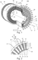
- FIG. 1 and 2 a perspective and a partial cross section view of a stator 10 for an electrical machine 100 according to an embodiment of the invention is described.
- Fig. 2 illustrates an enlarged cross section view of the embodiment of Fig. 1 .
- Fig. 3 illustrates a perspective and a partial cross section view of a stator 10 according to an embodiment of the invention without the winding coil arrangement 50 and without the stator back yoke 60 for illustration.
- Fig. 4 illustrates an enlarged cross section view of the embodiment of Fig. 3 .
- Figs. 5 and 6 refer to a method of manufacturing the stator 10 as described in the following.
- the stator 10 includes a stator tube 20 which defines a central axis c.
- the stator tube 20 includes a first side 21 and a second side 22 axially displaced from each other.
- the stator tube 20 further includes a stator tube wall 25 along the circumference 24 having a stator tube wall thickness 26 as more clearly illustrated in Fig. 2 .
- the stator tube wall thickness 26 may be constant along the circumference 24 of the stator tube 20.
- the stator 10 includes a plurality of stator teeth 30.
- the plurality of stator teeth 30 is disposed along the circumference 24 of the stator tube 20.
- Each of the stator teeth 30 extend from the first side 21 to the second side 22 of the stator tube 20 to define stator slots 37, see Figs. 3 and 4 , between the stator teeth 30.
- the number of stator teeth 30 and the number of stator slots 37 is equal to 36.
- the invention is not restricted thereto and also a different number of stator slots/teeth can be provided.
- a bottom portion 32 of each of the plurality of stator teeth 30 is embedded in the stator tube wall 25 of the stator tube 20 to bond the stator teeth 30 with the stator tube 20.
- the bottom portion 32 is entirely integrated in the stator tube wall 25 and thereby bonded with the stator tube 20.
- the bottom portion 32 is entirely surrounded by stator tube material.
- This configuration can be obtained by overmolding the stator teeth 30 in the process of forming the stator tube 20 as will be illustrated in Fig. 6 and the description thereto. Since the stator teeth 30 are bond to the stator tube 20 the buckling failure problem is eliminated. Therefore, the stator tube wall thickness 26 can be reduced to a minimum which results in an increase of power density and electromagnetic performance.
- each of the stator teeth 30 may include a laterally extending foot portion 31 at the bottom portion 32 of the stator teeth 30. That means the laterally extending foot portion 31 may circumferentially extend. Further, the laterally extending foot portion 31 axially extends from the first side 21 to the second side 22 along a length of the stator tooth 30. Also here, the laterally extending foot portion 31 is embedded in the stator tube wall 25, as indicated in Fig. 2 . Thus, the entire foot portion 31 of the stator teeth 30 is integrated/immersed in the stator tube wall 25 to be bond to the stator tube 20. This configuration including the foot portion 31 increases the coupling strength of the stator teeth 30 with the stator tube 20.
- Each of the stator teeth 30 include side surfaces 34, 35.
- these side surfaces 34, 35 may include a coating 40.
- the coating 40 is of a same stator tube material as the stator tube 20 and thus produced in the same process.
- the coating 40 can be formed in the overmolding process together with the forming of the stator tube 20 itself as will be explained in more detail below.
- the coating 40 may be integrally formed with the stator tube 20 and the stator tube wall 25 thereof. Since the stator teeth 30 are usually laminated, they include sharp edges.
- the coating 40 on the side surfaces 34, 35 may prevent that an insulation of the wave winding coils 51 is damaged by the sharp edges of the stator teeth 30.
- a front surface 36 and the back surface may also include the coating 40.
- Each of the stator teeth 30 may have a constant stator tooth width 33, i.e., the tangential thickness over the radial length. This can be seen well in Fig. 2 or Fig. 4 .
- each stator slot 37 may be wider at an outer periphery compared to an inner periphery. This is in particular illustrated in Figs. 2 and 4 and used as explained in the following.
- a stator tooth width 33 of the stator teeth 30 is constant along the height direction.
- a coating width 43 of the coating 40 on the at least one side surfaces 34, 35 of the stator tooth 30 may increase in the height direction, i.e. in direction away from the central axis c.
- the effective stator slot width 38 is relatively constant in height direction (direction away from the central axis c) or at least only slightly widening as indicated in Fig. 4 . This may be useful for the stacking of copper wire or profiled Litz wire or profiled solid copper wire.
- the coating 40 on the side surfaces 34, 35 of the stator teeth 30 include coolant channels 41.
- the coolant channels 41 extend axially from the first side 21 to the second side 22 of the stator tube 20.
- the coating 40 on the side surfaces 34, 35 is used to integrate coolant channels 41 along the stator teeth 30 to cool the wave winding coils 51 in operation.
- the coolant channels 41 may be formed symmetrically on both sides of each stator tooth 30 so that each stator tooth 30 contributes to the cooling of both stator slots 37 adjacent to the stator tooth 30. Therefore, liquid coolant or other coolant can flow through the active length next to the heat generating winding coil wires in the stator slots 37.
- the at least one coolant channel 41 can be formed in a corresponding coolant rib 42 which axially extends from the first side 21 to the second side 22 of the stator tube 20.
- the coolant ribs 42 may allow only local widening of the stator slot width so to minimize the reduction on the stator slot volume caused by the coolant channels 41.
- a plurality of coolant ribs 42 (here exemplarily 5 visible coolant ribs) are provided on each side surface 34, 35 of the stator teeth 30.
- two neighboring coolant ribs 42 may constitute a coolant channel 41.
- the diameter of the coolant channel/coolant rib 41/42 may increase with the distance from the central axis c. Thus, more coolant may be carried in the coolant channels 41 farther away from the central axis c. This may be the result of optimizing the available space in the stator slots 37 and to provide sufficient stator slot width 38 for the wave winding coils 51 supported therein.
- the at least one coolant rib 42 and/or the at least one coolant channel 41 is formed at a height in the stator slot 37 corresponding to a height of a wave winding coil 51 or a conductive portion thereof among a plurality of wave winding coils 51 stacked on top of each other in the stator slot 37.
- This is for example shown in Fig. 4 , where in this example 6 turns of wave winding coils 51 are stacked on top each other.
- the coolant ribs 41 may be provided on the same height as the turns wave winding coils 51 as indicated in Fig. 2 .
- each of the turns of the wave winding coils 51 may be subject to local cooling by one corresponding coolant channel/coolant rib 41/42.
- a winding coil arrangement 50 is wound along the circumference 24 of the stator tube 20.
- the winding coil arrangement 50 is supported by the stator slots 37 formed between the stator teeth 30.
- the winding coil arrangement 50 may include a plurality of wave winding coils 51.
- a plurality of wave winding coils 51 For example, in the present case, 18 wave winding coils 51 are provided.
- First ends 55 of the wave winding coils 51 may provide connectors to connect the winding coil arrangement 50 with power electronics 80 to operate the stator 10 as part of an electrical machine 100.
- Second ends of the wave winding coils 51 may be connected to a neutral point/phase to provide a star connection (here not shown).
- the winding coil arrangement 50 On the front side 21 (and on the second side 22, here not shown), the winding coil arrangement 50 includes three winding layers 52, 53, 54 to provide the winding coil arrangement 50, but the invention is not restricted thereto and any other winding arrangement may be provided.
- the winding layers 52, 53, 54 at the first side 21 are partially supported by a conical tip portion 27 of the stator tube 20 extending in axial direction C. This is also illustrated in Fig. 3 or Fig. 6 (e) for example. Due to the support by the conical tip portion 27 an improved installation process is enabled and (central) axial space, e.g. for a rotor, secured.
- a plurality of connectors 55 lead out from an outer diameter 58, indicated in Fig. 1 , of the wave winding coil arrangement 50.
- the connectors 55 can be provided from an outer diameter 58 instead of from an inner diameter in case of when the wave winding coil arrangement is installed from the inside.
- a more space efficient lead out arrangement can be provided with reduced axial space requirements.
- the stator 10 in this particular case comprises 18 wave winding coils 51 that can be grouped to 6 electric 3-phase lanes, of which groups of three may be operated synchronously, and where the two groups are operated none-synchronously, shifted 30 electrical degrees, to achieve a geometrically 6-phase electric machine.
- the present invention does not depend on a particular 6-phase electrical machine and the above is only an example of a winding coil arrangement 50.
- a 3-phase electrical machine may be provided or any other electrical machines.
- a stator back yoke 60 is mechanically coupled with the stator teeth 30 to surround the stator tube 20 along the circumference.
- the stator back yoke 60 encloses the winding coil arrangement 50.
- the stator back yoke 60 may include a plurality of coupling members along a circumference of the stator back yoke 60.
- each of the stator teeth 30 may include coupling members at a top portion of each stator tooth 30 which mechanically interlock with the coupling members of the stator back yoke 60.
- a dovetail interlock or dovetail coupling may be provided. Such dovetail interlock may be obtained by axially sliding the stator back yoke 60 onto the stator teeth 30 while the coupling members fit into each other. Due to the interlocking of coupling members form the first side 21 to the second side 22, a friction coupling is provided to secure the stator back yoke 60 on the plurality of stator teeth 30. Thus, an effective and stable coupling of the stator back yoke 60 is achieved.
- stator 10 as described above in various embodiments may be part of an electrical machine 100 which includes the stator 10 according to any of the above embodiments.
- power electronics 80 may be connected to connectors 55 of the stator 10.
- a rotor here not shown, is coaxially surrounded by the stator 10 and can be rotated around the central axis c in operation.
- An air gap here not visible, is formed between the rotor and the stator 10 in the electrical machine 100.
- a method of manufacturing of a stator 10 for an electrical machine 100 is disclosed.
- the method includes the step of forming S100 a stator tube 20 by molding.
- bonding of the plurality of stator teeth 30 with the stator tube 20 is achieved by overmolding the plurality of stator teeth 30 along a circumference 24.
- the bonding of the stator teeth 30 to the stator tube 20 is provided by overmolding the stator teeth 30. In this way, a bonding of each of the stator teeth 30 to the stator tube 20 is achieved which eliminates the failure problem of buckling.
- a bottom portion 32 of the plurality of stator teeth 30 is embedded in a stator tube wall 25 of the stator tube 20 as the result of the overmolding of the stator teeth 30.
- each of the stator teeth 30 extend from the first side 21 to the second side 22 of the stator tube 20 to define stator slots 37 between each neighboring stator teeth 30.
- a stator tube mold tool 70 may be provided.
- the stator tube mold tool 70 includes a plurality of preformed stator tooth cavities 72 formed at predefined positions along a circumference of the stator tube mold tool 70. Theses stator tooth cavities 72 are preprocessed to correspond to the stator teeth 30.
- the stator tooth cavities 72 may reserve space or particular profile for allowing stator tube material to cover the surfaces of the stator teeth 30 according to various embodiments as explained below.
- the method may include the step of assembling a plurality of stator teeth 30 in the respective stator tooth cavities 72 of the stator tube mold tool 70 along the circumference 24. As shown in Fig. 6 (b) , the process step is finished once the stator tooth cavities 72 are filled with corresponding the stator teeth 30. Then, the assembly process is finalized.
- the method may include the step of inserting a stator tube block 74 into a center of the stator tube mold tool 70.
- the stator tube block 74 may be a cylinder-shaped block.
- the stator tube block 74 may define an inner diameter of the stator tube 20 as it excludes stator tube material to enter the inner diameter during the molding process as explained below.
- stator tube mold tool 70 may be closed or sealed.
- the method may include the step of injecting a stator tube material into the stator tube mold tool 70.
- the stator tube 20 is formed and, at the same time, the plurality of stator teeth 30 are bond to the stator tube 20 (that is formed at the same time) due to the overmolding.
- the stator tube material may be a thermoplastic, preferably a polymer or a reinforced polymer.
- the stator tube 20 is formed with bonded stator teeth 30 disposed along the circumference 24 of the stator tube 20. Due to the predefined stator tooth cavities 72 predefined in the stator tube mold tool 70 a precise and correct positioning of the stator teeth 30 on the stator tube 20 may be achieved.
- stator tube 20 is provided accordance with Fig. 4 as the result of the forming process.
- Each of the stator teeth 30, once bonded with the stator tube 20, extend from the first side 21 to the second side 22 to provide stator slots 37 between each neighboring stator teeth 30.
- stator slots 37 are outwardly open. Due to the circular arrangement, the number of stator slots 37 equals the number of stator teeth 30, i.e., in the present example, there is 36 stator slots 37 provided in total. However, the present invention is not restricted thereto and a different number of stator slots/teeth 30, 37 may be provided.
- the step of forming S100 the stator tube 20 may include forming a coating 40 on side surfaces 34, 35 of each of the stator teeth 30. This is shown in Fig. 6 (e) and can be provided in the molding process to allow stator tube material to cover the side surfaces 34, 35 of the assembled stator teeth 30. Thus, sharp edges of the laminated stator teeth 30 are covered by stator tube material preventing damage to insulation of wave winding coils during installation.
- a stator tooth width 33 of the stator teeth 30 may be constant.
- the stator tooth 30 can have the same tangential thickness over the radial length.
- an effectively substantially constant stator slot width 38 may be provided as described in the following.
- the method may include in the step of forming S100 the stator tube 20 a coating width 43 of the coating 40 on the at least one side surface 34, 35 of the stator teeth 30 which increases in a direction away from the central axis c.
- This can be achieved by preprocessing the stator tooth cavities 72.
- the coating 40 i.e. by stator tube material, substantial weight is reduced compared to when widening the stator teeth in peripheral direction. Thus, weight reduction is achieved.
- the method of forming S100 the stator tube 20 may include the step of forming on at least one of the side surfaces 34, 35 of the stator teeth 30 at least one coolant channel 41 axially extending from the first side 21 to the second side 22 of the stator tube 20.
- the additional coating 40 is beneficially used to integrate coolant channels 41.
- These coolant channels 41 can be generated in the molding process. For example, this can be done by providing profiles.
- the coolant channels 41 can be provided in coolant ribs 42 that extend from the first side 21 to the second side 22 of the stator tube 20 as explained above. As well the coolant ribs 42 can be generated after the molding process or also by using forming tools in the molding process.
- the cooling channels 41 allow cooling liquid to flow directly through the active length next to the heat generating winding coils 51.
- the forming S100 may include that the coolant rib 42 and/or the at least one coolant channel 41 is formed at a height in the stator slot 37 corresponding to a height of a wave winding coil 51 among a plurality of wave winding coils 51 stacked on top of each other in the stator slot 37.
- each of the heat producing winding coils 51 is locally cooled by a corresponding coolant channel 41 or coolant rib 42.
- the method includes the step of installing S200, from the outside, a winding coil arrangement 50 along the circumference 24 of the stator tube 20. Since the stator slots 37 are open to the outside, the winding installation is simplified and can be performed in an automated/robotic manner. However, it is pointed out that the present invention does not depend on a particular winding coil arrangement 50.
- the winding coil arrangement 50 is supported by the stator slots 37 formed between the mechanically coupled stator teeth 30 on the outer surface 23 of the stator tube 20.
- Fig. 6 (f) a final state of the winding coil arrangement 50 is illustrated. In this state, three winding layers 52, 53, 54 are formed at the first side 21 and on the second side 22 (not visible).
- the method now further, as illustrated in Fig. 6 includes mechanically coupling S300 a stator back yoke 60 with the plurality of stator teeth 30 to surround the stator tube 20 and to enclose the winding coil arrangement 50.
- the stator back yoke 60 is slid onto the stator teeth 30 from the first side 21 or the second side 22.
- the mechanical coupling S300 of the stator back yoke 60 includes a sliding of the stator back yoke 60 in axial direction C while coupling members (here not shown) are fitting with coupling members of the stator teeth 30.
- a sliding dovetail interface is used.
- the method may include leading out the connectors 55 and the respective second ends of the wave winding coils 51.
- the second ends may be connected to a corresponding neutral phase for star connection.
- the above number of wave winding coils 51 is only an example and various other wave winding coil arrangements 50 can be used.
- the method may further include a step of cooling the stator back yoke 60 before mechanically coupling S300 a stator back yoke 60 with the plurality of stator teeth 30.
- This can be used for providing a greater clearance in the coupling interface, in particular dovetail interface, during assembly.
- the process of thermal equilibration may lead to an additional arresting force of the stator back yoke 60 due to thermal expansion while in the coupled state on the stator teeth 30.
- stator 10 and a manufacturing process is provided that entirely prevents the buckling failure mechanism to occur since all stator teeth 30 are bond with the stator tube 20.
- the bonding can be obtained by overmoulding the stator teeth 30 in the process of forming the stator stube 20.
- stator tube wall thickness 26 of the stator tube 20 can be reduced and therefore the power density of optimized.
- the stator back yoke 60 is coupled after the winding coil arrangement is completed, the wave winding coil arrangement 50 can be installed from the outside which eases the winding installation and enables automized/robotized installation.
Landscapes
- Engineering & Computer Science (AREA)
- Power Engineering (AREA)
- Manufacturing & Machinery (AREA)
- Manufacture Of Motors, Generators (AREA)
Abstract
According to an embodiment of the invention, a stator (10) for an electrical machine and a corresponding manufacturing method is provided. The stator (10) includes a stator tube (20) defining a central axis (c) and including a first side (21) and a second side (22) axially displaced from each other. A plurality of stator teeth (30) along a circumference (24) of the stator tube (20), wherein each of the stator teeth (30) extends from the first side (21) to the second side (22) of the stator tube (20) to define stator slots (37) between each neighboring stator teeth (30). At least a bottom portion (32) of each of the plurality of stator teeth (30) is embedded in a stator tube wall (25) of the stator tube (20) to bond the stator teeth (30) with the stator tube (20). a winding coil arrangement (50) wound along the circumference (24) of the stator tube (20) and supported by the stator slots (37) formed between the stator teeth (30) of the stator tube (30). A stator back yoke (60) is coupled with the stator teeth (30) to surround the stator tube (20) and to enclose the winding coil arrangement (50).
Description
- The present disclosure relates to a method of manufacturing a stator, a stator for an electrical machine and a corresponding electrical machine. In another aspect, the invention refers to an aircraft including the electrical machine.
- Electrical machines can generate a rotary motion of a rotor from a supplied electrical power or can generate electrical power using a supplied rotary motion depending on the mode of operation. The electrical machines include a stator and a rotor, wherein the rotor can rotate relative to the stator while the stator is immobilized.
- When the electrical machine is operated as a motor, the stator receives an electrical power to generate a rotating magnetic field. In such case, the rotating magnetic field interacts with the rotor and causes the rotor to perform a rotating motion that is transferable to a mechanically coupled shaft to provide a rotation motion to a consumer based on the input electrical power. When the electrical machine is operated as a generator, a rotating motion of the rotor causes a voltage and/or a current which can be provided to an electric power consumer based on the input kinetic (rotation) energy.
- The stator mechanically supports one or more coil windings which produce the rotating magnetic field or generate the electrical power depending on the mode of operation of the electrical machine.
- The stator includes a stator tube which seals the flooded stator and prevents any stator coolant from entering into the air gap between stator and rotor as well as into the inner rotor compartment. Present solutions typically include a thin-walled stator tube through the air gap surrounding the rotor.
- This stator tube is exposed to external coolant pressure and thus prone to buckling due to the thin stator tube wall thickness of the stator tube. The physical air gap between the stator tube and the rotating rotor must be maintained to limit air gap windage losses. Therefore, the stator tube wall thickness adds to the total magnetic air gap distance between stator and rotor and thus reduces power density and machine performance. Therefore, key performance features of the stator are maximized buckling strength at minimum wall thickness.
- Furthermore, winding coil installation is difficult when the stator slots are open to the central axis of the stator tube and usually has to be done manually. This is the result of limited space available in the interior of a stator tube and the problem of limited space amplifies when using increasingly complex winding arrangements that need to be installed to provide higher power efficiency and a more reliable operation.
- The present invention provides a method of manufacturing of a stator, a stator and an electrical machine including the stator which solves at least some of the above-mentioned problems. In addition, further technical problems in the above context are solved which become apparent from the following description.
- The invention is defined by the appended claims. The description that follows is subjected to this limitation. Any disclosure lying outside the scope of said claims is only intended for illustrative as well as comparative purposes.
- According to one aspect of the present disclosure, a stator for an electrical machine is provided. The stator includes a stator tube defining a central axis and including a first side and a second side axially displaced from each other. The stator includes a plurality of stator teeth along a circumference of the stator tube, wherein each of the stator teeth extends from the first side to the second side of the stator tube to define stator slots between each neighboring stator teeth. At least a bottom portion of each of the plurality of stator teeth is embedded in a stator tube wall of the stator tube to bond the stator teeth with the stator tube. The stator includes a winding coil arrangement wound along the circumference of the stator tube and supported by the stator slots formed between the stator teeth of the stator tube. The stator back yoke is coupled with the stator teeth to surround the stator tube and to enclose the winding coil arrangement.
- According to another aspect of the present disclosure, a method of manufacturing a stator for an electrical machine is provided. The method includes forming a stator tube and bonding a plurality of stator teeth with the stator tube by overmolding the plurality of stator teeth along a circumference of the stator tube so that at least a bottom portion of the plurality of stator teeth is embedded in a stator tube wall of the stator tube, wherein each of the stator teeth extends from the first side to the second side of the stator tube to define stator slots between each neighboring stator teeth. The method includes the step of installing, from the outside, a winding coil arrangement along the circumference of the stator tube and support the winding coil arrangement by the stator slots of the stator tube. The method includes the step of mechanically coupling a stator back yoke with the plurality of stator teeth to surround the stator tube and to enclose the winding coil arrangement.
- Yet another aspect of the present disclosure refers to an electrical machine including the stator and an aircraft including the electrical machine.
- Further aspects of the present disclosure could be learned from the dependent claims or the following description.
- Features will become apparent to those of ordinary skill in the art by describing in detail exemplary embodiments with reference to the attached drawings in which:
- Fig. 1
- illustrates a perspective view and a partial cross section view of a stator according to an embodiment of the invention,
- Fig. 2
- illustrates an enlarged cross section view of the embodiment of
Fig. 1 , - Fig. 3
- illustrates a perspective view and a partial cross section view of a stator according to an embodiment of the invention without the winding coil arrangement and without the stator back yoke for illustration,
- Fig. 4
- illustrates an enlarged cross section view of the embodiment of
Fig. 3 , - Fig. 5
- illustrates schematically a method of manufacturing a stator according to an embodiment of the invention, and
- Fig. 6
- illustrates a method of manufacturing a stator according to an embodiment of the invention.
- Reference will now be made in detail to embodiments, examples of which are illustrated in the accompanying drawings. Effects and features of the exemplary embodiments, and implementation methods thereof will be described with reference to the accompanying drawings. In the drawings, like reference numerals denote like elements, and redundant descriptions are omitted. The present disclosure, however, may be embodied in various different forms, and should not be construed as being limited to only the illustrated embodiments herein. Rather, these embodiments are provided as examples so that this disclosure will be thorough and complete, and will fully convey the aspects and features of the present disclosure to those skilled in the art.
- Accordingly, processes, elements, and techniques that are not considered necessary to those having ordinary skill in the art for a complete understanding of the aspects and features of the present disclosure may not be described. In the drawings, the relative sizes of elements, layers, and regions may be exaggerated for clarity.
- As used herein, the term "and/or" includes any and all combinations of one or more of the associated listed items. Further, the use of "may" when describing embodiments of the present disclosure refers to "one or more embodiments of the present disclosure." In the following description of embodiments of the present disclosure, the terms of a singular form may include plural forms unless the context clearly indicates otherwise.
- It will be understood that although the terms "first" and "second" are used to describe various elements, these elements should not be limited by these terms. These terms are only used to distinguish one element from another element. For example, a first element may be named a second element and, similarly, a second element may be named a first element, without departing from the scope of the present disclosure. As used herein, the term "and/or" includes any and all combinations of one or more of the associated listed items. Expressions such as "at least one of," when preceding a list of elements, modify the entire list of elements and do not modify the individual elements of the list.
- It will be further understood that the terms "include," "comprise," "including," or "comprising" specify a property, a region, a fixed number, a step, a process, an element, a component, and a combination thereof but do not exclude other properties, regions, fixed numbers, steps, processes, elements, components, and combinations thereof.
- It will also be understood that when a film, a region, or an element is referred to as being "above" or "on" another film, region, or element, it can be directly on the other film, region, or element, or intervening films, regions, or elements may also be present.
- Herein, the terms "upper" and "lower" are defined according to the z-axis. For example, the upper cover is positioned at the upper part of the z-axis, whereas the lower cover is positioned at the lower part thereof. In the drawings, the sizes of elements may be exaggerated for clarity. For example, in the drawings, the size or thickness of each element may be arbitrarily shown for illustrative purposes, and thus the embodiments of the present disclosure should not be construed as being limited thereto.
- Unless otherwise defined, all terms (including technical and scientific terms) used herein have the same meaning as commonly understood by one of ordinary skill in the art to which the present disclosure belongs. It will be further understood that terms, such as those defined in commonly used dictionaries, should be interpreted as having a meaning that is consistent with their meaning in the context of the relevant art and/or the present specification, and should not be interpreted in an idealized or overly formal sense, unless expressly so defined herein.
- According to one aspect of the present disclosure, a stator for an electrical machine is provided. The stator includes a stator tube with a central axis and including a first side and a second side axially displaced from each other. The stator includes a plurality of stator teeth disposed along a circumference of the stator tube, wherein each of the stator teeth extends from the first side to the second side of the stator tube to define stator slots between each neighboring stator teeth. At least a bottom portion of each of the plurality of stator teeth is embedded or immersed in a stator tube wall of the stator tube or fully surrounded by the stator tube wall of the stator tube to bond or connect the stator teeth with the stator tube. The stator includes a wave winding coil arrangement wound along the circumference of the stator tube which is supported by the stator slots formed between the stator teeth of the stator tube. A stator back yoke is coupled with the stator teeth to surround the stator tube and to enclose the winding coil arrangement.
- Embedded may mean in other words immersed in the stator tube wall. In other terms, a bottom portion of the stator teeth may be entirely surrounded by stator tube wall and the stator tube material of the stator tube wall. The bottom portion of the stator teeth is thus merged with the stator tube wall. The bonding and the embedding of the bottom portion of the stator teeth in the stator tube wall may be obtained by overmolding the stator teeth in the process of forming the stator tube. The bonding may be obtained by a molding process. A winding coil arrangement may include a plurality of wave winding coils. A wave winding coil includes a continuous, or uniform, conductor that is wound around the circumference of the stator tube. Each wave winding coil may correspond to a magnetic pole in operation. The wave winding coils refer to flexible conductors which can be bend and/or twisted at the first (front) side and/or the second (back) side of the stator tube to allow windings for forming a wave winding arrangement. At each side of the stator tube windings may be formed to provide different turns. Each of the wave winding coils include insulation so that different wave winding coils are electrically insulated from one another even if overlayed on top of each other. The wave winding coils may each include multiple conductors in a Litz wire arrangement to increase electric current transport. The number of stator slots may be 36 but any other number may be provided. The number of wave windings coils may be 18 but any other number may be provided. The first side may be a front side and the second side may be a back side. The stator tooth may include a magnetic material like laminated steel.
- The above-described stator eliminates buckling due to the bonding of the stator teeth with the stator tube. This has an additional advantage of that the wall thickness of the stator tube wall can be made less thick thereby improving power density due to increased electromagnetic performance arising from the reduced stator tube wall thickness as the result of a reduced magnetic air gap. In detail, the thickness of the stator tube can be reduced to an absolute minimum as the thickness is determined only by the necessary strength to withstand external coolant pressure across the tooth tip width and not the whole circumference. Further, reliability can be improved since the stator tube buckling failure mechanism due to external coolant pressure is eliminated. In addition, since the back yoke is coupled after the winding coil arrangement is completed, the wave winding coil arrangement can be installed from the outside. This has the effect of an easier winding installation. Such a winding installation can for example be automized/robotized instead of be performed manually which is not possible or at least very difficult for a winding installation to be performed from the inside. Further, the invention eliminates the need for a sophisticated stator tube composite material. Instead, low-cost materials may be used due to the improved buckling strength.
- According to an embodiment, each of the stator teeth includes a laterally extending foot portion at the bottom portion of the stator teeth axially extending from the first side to the second side, and the laterally extending foot portion is embedded in the stator tube wall. In other words, the laterally extending foot portion may be a laterally extending portion, e.g., formed like a reversed T in an axial view. The laterally extending foot may extend in circumferential direction. This laterally extending foot portion may stabilize the bonding of the stator teeth to the stator tube. The laterally extending foot portion may be positioned substantially in the center (middle) of the stator tube wall so that a coating of stator tube material above and below the laterally extending foot portion is formed. These coatings may have the same or approximately the same height.
- According to an embodiment, side surfaces of each of the stator teeth include a coating which is of a same stator tube material as the stator tube. This implies that the stator teeth are fully coated by the stator tube material. This has the advantage that a winding coil insulation can be protected from being damaged or cut by sharp lamination edges during the winding installation. This is since the coating of the stator tube material can prevent a direct contact of winding coil insulation and (laminated) stator teeth. In particular, the stator tube material is relatively soft, e.g. a thermoplastic or more general polymer material, compared to the stator tooth material and thus prevents destruction of the winding coil insulation.
- According to an embodiment, the coating on at least one of the side surfaces of the stator teeth includes at least one coolant channel extending in axial direction from the first side to the second side. The invention utilizes the fact that the stator teeth can have the same tangential thickness over the radial length, allowing for a wider stator slot width at the outer periphery. In the cases of using profiled Litz-, or profiled solid copper wire, this additional stator slot width can be used for coolant channels. Thus, the coating is used to provide integrated coolant channels. This allows cooling channels directly next to the winding coil wires in the active length next to the winding coil. This enables increased power density due to increased robustness against overheating.
- According to an embodiment, the at least one coolant channel is formed in a corresponding coolant rib which axially extends from the first side to the second side. The coolant ribs may allow only local narrowing of the effective slot width. This may be favorable to minimize stator slot volume reduction caused by the coolant channels.
- According to an embodiment, the at least one coolant rib and/or the at least one coolant channel is formed at a height in the stator slot corresponding to a height of a wave winding coil among a plurality of wave winding coils stacked on top of each other in the stator slot. Thus, a local cooling along the active length of respective wave winding coils is provided. An equality of the vertical position of the coolant ribs and/or coolant channel ensure close contact to a corresponding wave winding coil.
- According to an embodiment, a width of the stator teeth is constant and a width of the coating on the at least one side surface of the stator tooth increases in a direction away from the central axis. In typical solutions to provide parallel winding slots sloped stator teeth are used that are wider at the outer periphery than the inner. Additional weight is saved by replacing this non-utilized lamination material with a light weigh stator tube material, e.g. typically reinforced polymer or other thermoplastics, and low-density coolant fluid. This weight reduction scales with the number of stator teeth. Thus, the entire stator weight is substantially reduced and additionally allows the integrated function of coolant channels.
- According to another aspect of the present disclosure, a method of manufacturing a stator for an electrical machine. The stator may be the stator as disclosed above or in the following description. The method includes forming a stator tube and bonding a plurality of stator teeth with the stator tube in a process of overmolding the plurality of stator teeth along a circumference so that at least a bottom portion of the plurality of teeth is embedded in a stator tube wall of the stator tube, wherein each of the stator teeth extends from the first side to the second side of the stator tube to define stator slots between each neighboring stator teeth. The method includes the step of installing, from the outside, a winding coil arrangement along the circumference of the stator tube and support the winding coil arrangement by the stator slots of the stator tube. The method includes the step of mechanically coupling a stator back yoke with the plurality of stator teeth to surround the stator tube and to enclose the winding coil arrangement.
- The achieved advantages correspond to the above stator for an electrical machine. The bonding and the embedding of the bottom portion of the stator teeth in the stator tube wall are obtained by an overmolding of the stator teeth in the process of forming the stator tube. Thus, the bonding is achieved by a common molding process. The stator eliminates buckling due to the bonding of the stator teeth with the stator tube. This has an additional advantage of that the wall thickness of the stator tube wall can be made less thick thereby improving power density due to increased electromagnetic performance due to the reduced stator tube wall thickness as the result of a reduced magnetic air gap. In detail, the thickness of the stator tube can be reduced to an absolute minimum as the thickness is determined only by the necessary strength to withstand external coolant pressure across the tooth tip width and not the whole circumference. In addition, since the back yoke is coupled after the winding coil arrangement is completed, the wave winding coil arrangement can be installed from the outside. This has the effect of an easier winding installation. Such a winding installation can for example be automized/robotized instead of be performed manually which is not possible or at least very difficult for a winding installation to be performed from the inside. Further, the invention eliminates the need for a sophisticated stator tube composite material. Instead, low-cost materials may be used due to the improved buckling strength.
- According to an embodiment, the method may include the step of providing a stator tube mold tool including a plurality of stator tooth cavities formed at predefined positions along a circumference of the stator tube mold tool. The method includes assembling a plurality of stator teeth in the stator tooth cavities of the stator tube mold tool. The method includes inserting a stator tube block into a center of the stator tube mold tool. The method includes performing a step of injecting a stator tube material into the stator tube mold tool to produce the stator tube and to bond the plurality of stator teeth with the plurality of stator teeth. This method has the effect that the stator teeth are automatically and precisely fixed in the correct position on the stator tube due to the predefined stator teeth cavities in the mold tool. These predefined stator tooth cavities can be provided equidistant along the circumference. This leads to positional precision and reduced variance in production.
- According to an embodiment, each of the stator teeth includes a laterally extending foot portion at the bottom portion of the stator teeth axially extending in the axial direction, wherein the step of overmolding is performed to embed the laterally extending foot portion in the stator tube wall. As mentioned above, the laterally extending foot may extend in circumferential direction. This laterally extending foot portion may stabilize the bonding of the stator teeth to the stator tube. The laterally extending foot portion may be positioned substantially in the center (middle) of the stator tube wall so that a coating of stator tube material above and below the laterally extending foot portion is formed. These coatings may have the same or approximately the same height.
- According to an embodiment, the step of forming the stator tube includes forming of a coating on side surfaces of each of the stator teeth. This can be achieved by allowing same space in the stator tooth cavities for stator tube material to cover the stator teeth. It implies that the stator teeth are fully coated by the stator tube material. This has the advantage that a winding coil insulation can be protected from being damaged or cut by sharp lamination edges during the winding installation as mentioned above.
- According to an embodiment, the step of forming the stator tube includes forming on at least one of the side surfaces of the stator teeth at least one coolant channel extending in axial direction from the first side to the second side. The coolant channels may be formed by preprocessing or pre-processing of the stator tooth cavities to allow the formation of the coolant channels and/or coolant ribs in the molding process. Further, additional forming tools in the molding process may be used. Thus, the coating is used to provide integrated coolant channels. This allows cooling channels directly next to the winding coil wires in the active length next to the winding coil and leads to increased power density due to increased robustness against overheating.
- According to an embodiment, a width of the stator teeth is constant and the forming the stator tube includes forming a width of the coating on the at least one side surface of the stator tooth which increases in a direction away from the central axis. This feature may be obtained by properly preprocessing of the stator tooth cavities. Thus, a relatively constant width over the stator slot height may be achieved. The width increase of the coating may be gradual. Additional weight is saved by replacing a non-utilized lamination material of the stator tooth with a light weigh stator tube material, e.g. typically reinforced polymer or other thermoplastics, and low-density coolant fluid. This weight reduction scales with the number of stator teeth. Thus, the entire stator weight is substantially reduced and allows integrating above coolant channels.
- According to an embodiment, the method includes a step of cooling the stator back yoke before the step of mechanically coupling the stator back yoke with the plurality of stator teeth. Thus, cooling the back yoke vs. the stator tube, stator teeth and the winding assembly, prior to assembling to achieve a greater clearance in the dovetail interface during assembling. Further guiding tools may be used. The prior cooling may result in that the stator back yoke may have higher tolerances or clearance when being slid on the stator teeth and therefore eases the mechanical coupling process. Further, when being in the locking position and during the process of thermal equilibration, the prior cooling may lead to an additional coupling force/tension of the stator yoke due to thermal expansion while in coupled state on the stator teeth to improve coupling strength.
- According to an embodiment, the stator back yoke may include a plurality of coupling members along a circumference and extending in axial direction, and each of the stator teeth include a plurality of coupling members extending in axial direction, wherein each coupling member mechanically interlock with coupling members of the stator teeth. The coupling members may include a laterally extending or widening portion. In particular, the coupling members may include a trapezoidal shape when viewed in axial direction. The coupling member of the stator teeth may include a corresponding shape to receive or to fit the coupling member of the stator yoke therein. The coupling may be in other words a dovetail coupling or a sliding dovetail joint. In this way as described above, a stable fixation of the stator back yoke may be provided by the plurality of stator teeth. Thus, an interlocking of the stator back yoke to the stator teeth is achieved. Due to the fitting of the mating coupling members, a friction coupling is provided along the axial length after the sliding is completed to safely secure the stator back yoke on the plurality of stator teeth. In embodiments, additional glue may be used, but in other embodiments no additional glue may be used. Thus, an effective and stable coupling of the stator back yoke is achieved.
- According to an embodiment, an electrical machine including a stator according to embodiments of the present invention is provided. The electrical machine according to the embodiments of the stator may have higher power density due to thinner stator tube wall since the risk of buckling is eliminated due to the bonding of the stator teeth with the stator tube. Further advantages can be derived directly from the advantages of the stator.
- In addition, an aircraft comprising the electric machine is provided. In particular for aircrafts the above advantages are important for improving weight as well as safety and reliability of operation.
- According to
Figs. 1 and 2 a perspective and a partial cross section view of astator 10 for anelectrical machine 100 according to an embodiment of the invention is described.Fig. 2 illustrates an enlarged cross section view of the embodiment ofFig. 1 .Fig. 3 illustrates a perspective and a partial cross section view of astator 10 according to an embodiment of the invention without the windingcoil arrangement 50 and without the stator backyoke 60 for illustration.Fig. 4 illustrates an enlarged cross section view of the embodiment ofFig. 3 .Figs. 5 and6 refer to a method of manufacturing thestator 10 as described in the following. - Referring to
Figs. 1 to 4 , astator 10 for anelectrical machine 100 is provided. Thestator 10 includes astator tube 20 which defines a central axis c. Thestator tube 20 includes afirst side 21 and asecond side 22 axially displaced from each other. Thestator tube 20 further includes astator tube wall 25 along thecircumference 24 having a statortube wall thickness 26 as more clearly illustrated inFig. 2 . The statortube wall thickness 26 may be constant along thecircumference 24 of thestator tube 20. - The
stator 10 includes a plurality ofstator teeth 30. The plurality ofstator teeth 30 is disposed along thecircumference 24 of thestator tube 20. Each of thestator teeth 30 extend from thefirst side 21 to thesecond side 22 of thestator tube 20 to definestator slots 37, seeFigs. 3 and 4 , between thestator teeth 30. In the present case, the number ofstator teeth 30 and the number ofstator slots 37 is equal to 36. However, the invention is not restricted thereto and also a different number of stator slots/teeth can be provided. - Referring to
Figs. 1 to 4 and in particular the enlargedFigs. 2 and4 , at least abottom portion 32 of each of the plurality ofstator teeth 30 is embedded in thestator tube wall 25 of thestator tube 20 to bond thestator teeth 30 with thestator tube 20. Thus, thebottom portion 32 is entirely integrated in thestator tube wall 25 and thereby bonded with thestator tube 20. For example, thebottom portion 32 is entirely surrounded by stator tube material. This configuration can be obtained by overmolding thestator teeth 30 in the process of forming thestator tube 20 as will be illustrated inFig. 6 and the description thereto. Since thestator teeth 30 are bond to thestator tube 20 the buckling failure problem is eliminated. Therefore, the statortube wall thickness 26 can be reduced to a minimum which results in an increase of power density and electromagnetic performance. - Referring to
Figs. 2 and4 , each of thestator teeth 30 may include a laterally extendingfoot portion 31 at thebottom portion 32 of thestator teeth 30. That means the laterally extendingfoot portion 31 may circumferentially extend. Further, the laterally extendingfoot portion 31 axially extends from thefirst side 21 to thesecond side 22 along a length of thestator tooth 30. Also here, the laterally extendingfoot portion 31 is embedded in thestator tube wall 25, as indicated inFig. 2 . Thus, theentire foot portion 31 of thestator teeth 30 is integrated/immersed in thestator tube wall 25 to be bond to thestator tube 20. This configuration including thefoot portion 31 increases the coupling strength of thestator teeth 30 with thestator tube 20. - Each of the
stator teeth 30 include side surfaces 34, 35. Referring toFigs. 2 and4 , these side surfaces 34, 35 may include acoating 40. Thecoating 40 is of a same stator tube material as thestator tube 20 and thus produced in the same process. Thus, thecoating 40 can be formed in the overmolding process together with the forming of thestator tube 20 itself as will be explained in more detail below. In particular, thecoating 40 may be integrally formed with thestator tube 20 and thestator tube wall 25 thereof. Since thestator teeth 30 are usually laminated, they include sharp edges. Thecoating 40 on the side surfaces 34, 35 may prevent that an insulation of thewave winding coils 51 is damaged by the sharp edges of thestator teeth 30. Further, as shown inFig. 3 , afront surface 36 and the back surface (here not shown) may also include thecoating 40. - Each of the
stator teeth 30 may have a constantstator tooth width 33, i.e., the tangential thickness over the radial length. This can be seen well inFig. 2 orFig. 4 . Thus, eachstator slot 37 may be wider at an outer periphery compared to an inner periphery. This is in particular illustrated inFigs. 2 and4 and used as explained in the following. - Preferably, as mentioned above and indicated by referring to
Figs. 2 and4 , astator tooth width 33 of thestator teeth 30 is constant along the height direction. Further, acoating width 43 of thecoating 40 on the at least one side surfaces 34, 35 of thestator tooth 30 may increase in the height direction, i.e. in direction away from the central axis c. As a result, the effectivestator slot width 38 is relatively constant in height direction (direction away from the central axis c) or at least only slightly widening as indicated inFig. 4 . This may be useful for the stacking of copper wire or profiled Litz wire or profiled solid copper wire. However, since this is achieved by thecoating 40 additional weight is reduced by replacing the non-utilized lamination material with a light weigh stator tube material, e.g. typically reinforced polymer, and a low-density coolant fluid. This weight reduction scales with the number ofstator teeth 30. Thus, the entire weight of thestator 10 is substantially reduced. - As can be seen in
Figs. 2 and4 , thecoating 40 on the side surfaces 34, 35 of thestator teeth 30 includecoolant channels 41. Thecoolant channels 41 extend axially from thefirst side 21 to thesecond side 22 of thestator tube 20. Thus, thecoating 40 on the side surfaces 34, 35 is used to integratecoolant channels 41 along thestator teeth 30 to cool thewave winding coils 51 in operation. As can be seen inFig. 2 , thecoolant channels 41 may be formed symmetrically on both sides of eachstator tooth 30 so that eachstator tooth 30 contributes to the cooling of bothstator slots 37 adjacent to thestator tooth 30. Therefore, liquid coolant or other coolant can flow through the active length next to the heat generating winding coil wires in thestator slots 37. - Further, when referring to
Fig. 4 , the at least onecoolant channel 41 can be formed in acorresponding coolant rib 42 which axially extends from thefirst side 21 to thesecond side 22 of thestator tube 20. Thecoolant ribs 42 may allow only local widening of the stator slot width so to minimize the reduction on the stator slot volume caused by thecoolant channels 41. For example, as shown inFigs. 3 and 4 , a plurality of coolant ribs 42 (here exemplarily 5 visible coolant ribs) are provided on eachside surface stator teeth 30. For example, two neighboringcoolant ribs 42 may constitute acoolant channel 41. Due to more space in the periphery, the diameter of the coolant channel/coolant rib 41/42 may increase with the distance from the central axis c. Thus, more coolant may be carried in thecoolant channels 41 farther away from the central axis c. This may be the result of optimizing the available space in thestator slots 37 and to provide sufficientstator slot width 38 for thewave winding coils 51 supported therein. - Referring to
Fig. 4 , the at least onecoolant rib 42 and/or the at least onecoolant channel 41 is formed at a height in thestator slot 37 corresponding to a height of awave winding coil 51 or a conductive portion thereof among a plurality ofwave winding coils 51 stacked on top of each other in thestator slot 37. This is for example shown inFig. 4 , where in this example 6 turns ofwave winding coils 51 are stacked on top each other. Thecoolant ribs 41 may be provided on the same height as the turns wave windingcoils 51 as indicated inFig. 2 . Thus, each of the turns of thewave winding coils 51 may be subject to local cooling by one corresponding coolant channel/coolant rib 41/42. - Referring to
Fig. 1 , a windingcoil arrangement 50 is wound along thecircumference 24 of thestator tube 20. The windingcoil arrangement 50 is supported by thestator slots 37 formed between thestator teeth 30. - The winding
coil arrangement 50 may include a plurality ofwave winding coils 51. For example, in the present case, 18wave winding coils 51 are provided. First ends 55 of thewave winding coils 51 may provide connectors to connect the windingcoil arrangement 50 withpower electronics 80 to operate thestator 10 as part of anelectrical machine 100. Second ends of thewave winding coils 51 may be connected to a neutral point/phase to provide a star connection (here not shown). On the front side 21 (and on thesecond side 22, here not shown), the windingcoil arrangement 50 includes three windinglayers coil arrangement 50, but the invention is not restricted thereto and any other winding arrangement may be provided. - The winding layers 52, 53, 54 at the
first side 21 are partially supported by aconical tip portion 27 of thestator tube 20 extending in axial direction C. This is also illustrated inFig. 3 orFig. 6 (e) for example. Due to the support by theconical tip portion 27 an improved installation process is enabled and (central) axial space, e.g. for a rotor, secured. - A plurality of
connectors 55 lead out from anouter diameter 58, indicated inFig. 1 , of the wave windingcoil arrangement 50. Thus, since thewave winding arrangement 50 is provided from the outside before the stator backyoke 60 is coupled thereto as explained further below, theconnectors 55 can be provided from anouter diameter 58 instead of from an inner diameter in case of when the wave winding coil arrangement is installed from the inside. Thus, due to the winding installation from the outside, a more space efficient lead out arrangement can be provided with reduced axial space requirements. - The
stator 10 in this particular case comprises 18wave winding coils 51 that can be grouped to 6 electric 3-phase lanes, of which groups of three may be operated synchronously, and where the two groups are operated none-synchronously, shifted 30 electrical degrees, to achieve a geometrically 6-phase electric machine. However, the present invention does not depend on a particular 6-phase electrical machine and the above is only an example of a windingcoil arrangement 50. For example, also a 3-phase electrical machine may be provided or any other electrical machines. - Referring to
Fig. 1 , a stator backyoke 60 is mechanically coupled with thestator teeth 30 to surround thestator tube 20 along the circumference. Thus, the stator backyoke 60 encloses the windingcoil arrangement 50. - The stator back
yoke 60 may include a plurality of coupling members along a circumference of the stator backyoke 60. As well, each of thestator teeth 30 may include coupling members at a top portion of eachstator tooth 30 which mechanically interlock with the coupling members of the stator backyoke 60. In particular, a dovetail interlock or dovetail coupling may be provided. Such dovetail interlock may be obtained by axially sliding the stator backyoke 60 onto thestator teeth 30 while the coupling members fit into each other. Due to the interlocking of coupling members form thefirst side 21 to thesecond side 22, a friction coupling is provided to secure the stator backyoke 60 on the plurality ofstator teeth 30. Thus, an effective and stable coupling of the stator backyoke 60 is achieved. - Further, the
stator 10 as described above in various embodiments may be part of anelectrical machine 100 which includes thestator 10 according to any of the above embodiments. In addition,power electronics 80 may be connected toconnectors 55 of thestator 10. A rotor, here not shown, is coaxially surrounded by thestator 10 and can be rotated around the central axis c in operation. An air gap, here not visible, is formed between the rotor and thestator 10 in theelectrical machine 100. - According to
Figs. 5 and6 , a method of manufacturing of astator 10 for anelectrical machine 100 is disclosed. - The method includes the step of forming S100 a
stator tube 20 by molding. In the process of forming thestator tube 20 bonding of the plurality ofstator teeth 30 with thestator tube 20 is achieved by overmolding the plurality ofstator teeth 30 along acircumference 24. Thus, not only thestator tube 20 is formed in the molding process since, in the same instance, also the bonding of thestator teeth 30 to thestator tube 20 is provided by overmolding thestator teeth 30. In this way, a bonding of each of thestator teeth 30 to thestator tube 20 is achieved which eliminates the failure problem of buckling. - In particular, a
bottom portion 32 of the plurality ofstator teeth 30 is embedded in astator tube wall 25 of thestator tube 20 as the result of the overmolding of thestator teeth 30. Once bonded to thestator tube 20, each of thestator teeth 30 extend from thefirst side 21 to thesecond side 22 of thestator tube 20 to definestator slots 37 between each neighboringstator teeth 30. - The above process can be preferably implemented as in the following. Referring to
Fig. 6 (a) , a statortube mold tool 70 may be provided. The statortube mold tool 70 includes a plurality of preformedstator tooth cavities 72 formed at predefined positions along a circumference of the statortube mold tool 70. Theses statortooth cavities 72 are preprocessed to correspond to thestator teeth 30. In addition, thestator tooth cavities 72 may reserve space or particular profile for allowing stator tube material to cover the surfaces of thestator teeth 30 according to various embodiments as explained below. - Referring to
Fig. 6 (b) , the method may include the step of assembling a plurality ofstator teeth 30 in the respectivestator tooth cavities 72 of the statortube mold tool 70 along thecircumference 24. As shown inFig. 6 (b) , the process step is finished once thestator tooth cavities 72 are filled with corresponding thestator teeth 30. Then, the assembly process is finalized. - Referring to
Fig. 6 (c) , the method may include the step of inserting astator tube block 74 into a center of the statortube mold tool 70. Thestator tube block 74 may be a cylinder-shaped block. Thestator tube block 74 may define an inner diameter of thestator tube 20 as it excludes stator tube material to enter the inner diameter during the molding process as explained below. - In a further method step, once the
stator tube block 74 is inserted, the statortube mold tool 70 may be closed or sealed. - Referring to
Fig. 6 (d) , the method may include the step of injecting a stator tube material into the statortube mold tool 70. In this manner, thestator tube 20 is formed and, at the same time, the plurality ofstator teeth 30 are bond to the stator tube 20 (that is formed at the same time) due to the overmolding. The stator tube material may be a thermoplastic, preferably a polymer or a reinforced polymer. Thus, in a single forming or molding process, thestator tube 20 is formed with bondedstator teeth 30 disposed along thecircumference 24 of thestator tube 20. Due to the predefinedstator tooth cavities 72 predefined in the stator tube mold tool 70 a precise and correct positioning of thestator teeth 30 on thestator tube 20 may be achieved. - Referring to
Fig. 6 (e) , thestator tube 20 is provided accordance withFig. 4 as the result of the forming process. Each of thestator teeth 30, once bonded with thestator tube 20, extend from thefirst side 21 to thesecond side 22 to providestator slots 37 between each neighboringstator teeth 30. - The
stator slots 37 are outwardly open. Due to the circular arrangement, the number ofstator slots 37 equals the number ofstator teeth 30, i.e., in the present example, there is 36stator slots 37 provided in total. However, the present invention is not restricted thereto and a different number of stator slots/teeth - The step of forming S100 the
stator tube 20 may include forming acoating 40 on side surfaces 34, 35 of each of thestator teeth 30. This is shown inFig. 6 (e) and can be provided in the molding process to allow stator tube material to cover the side surfaces 34, 35 of the assembledstator teeth 30. Thus, sharp edges of thelaminated stator teeth 30 are covered by stator tube material preventing damage to insulation of wave winding coils during installation. - Further, as mentioned above, a
stator tooth width 33 of thestator teeth 30 may be constant. In other words, thestator tooth 30 can have the same tangential thickness over the radial length. For supporting for example profiled Litz- or profiled solid copper wire, an effectively substantially constantstator slot width 38 may be provided as described in the following. - For such configuration, the method may include in the step of forming S100 the stator tube 20 a
coating width 43 of thecoating 40 on the at least oneside surface stator teeth 30 which increases in a direction away from the central axis c. This can be achieved by preprocessing thestator tooth cavities 72. However, since this is achieved by thecoating 40, i.e. by stator tube material, substantial weight is reduced compared to when widening the stator teeth in peripheral direction. Thus, weight reduction is achieved. - Further, the method of forming S100 the
stator tube 20 may include the step of forming on at least one of the side surfaces 34, 35 of thestator teeth 30 at least onecoolant channel 41 axially extending from thefirst side 21 to thesecond side 22 of thestator tube 20. Thus, theadditional coating 40 is beneficially used to integratecoolant channels 41. Thesecoolant channels 41 can be generated in the molding process. For example, this can be done by providing profiles. - The
coolant channels 41 can be provided incoolant ribs 42 that extend from thefirst side 21 to thesecond side 22 of thestator tube 20 as explained above. As well thecoolant ribs 42 can be generated after the molding process or also by using forming tools in the molding process. The coolingchannels 41 allow cooling liquid to flow directly through the active length next to the heatgenerating winding coils 51. - Preferably, the forming S100 may include that the
coolant rib 42 and/or the at least onecoolant channel 41 is formed at a height in thestator slot 37 corresponding to a height of awave winding coil 51 among a plurality ofwave winding coils 51 stacked on top of each other in thestator slot 37. In this way, each of the heat producing windingcoils 51 is locally cooled by a correspondingcoolant channel 41 orcoolant rib 42. - Referring now to
Fig. 6 (f) , the method includes the step of installing S200, from the outside, a windingcoil arrangement 50 along thecircumference 24 of thestator tube 20. Since thestator slots 37 are open to the outside, the winding installation is simplified and can be performed in an automated/robotic manner. However, it is pointed out that the present invention does not depend on a particular windingcoil arrangement 50. - The winding
coil arrangement 50 is supported by thestator slots 37 formed between the mechanically coupledstator teeth 30 on the outer surface 23 of thestator tube 20. InFig. 6 (f) a final state of the windingcoil arrangement 50 is illustrated. In this state, three windinglayers first side 21 and on the second side 22 (not visible). - The method now further, as illustrated in
Fig. 6 includes mechanically coupling S300 a stator backyoke 60 with the plurality ofstator teeth 30 to surround thestator tube 20 and to enclose the windingcoil arrangement 50. The stator backyoke 60 is slid onto thestator teeth 30 from thefirst side 21 or thesecond side 22. - The mechanical coupling S300 of the stator back
yoke 60 includes a sliding of the stator backyoke 60 in axial direction C while coupling members (here not shown) are fitting with coupling members of thestator teeth 30. Preferably, a sliding dovetail interface is used. - Thus, an interlocking of the stator back yoke to the stator teeth is achieved. Due to the fitting of the mating coupling members, a friction coupling is provided along the entire axial length after the sliding is completed to secure the stator back
yoke 60 on the plurality ofstator teeth 30. Such final state after the mechanical coupling of the stator backyoke 60 is shown inFig. 2 (g). Guiding tools may be required to slide the stator backyoke 60 in a controlled manner. - Further, as shown in
Fig. 2 (g), depending on the numberwave winding coils 51 involved, the method may include leading out theconnectors 55 and the respective second ends of thewave winding coils 51. The second ends may be connected to a corresponding neutral phase for star connection. However, as already pointed out above, the above number ofwave winding coils 51 is only an example and various other wave windingcoil arrangements 50 can be used. - The method may further include a step of cooling the stator back
yoke 60 before mechanically coupling S300 a stator backyoke 60 with the plurality ofstator teeth 30. This can be used for providing a greater clearance in the coupling interface, in particular dovetail interface, during assembly. In particular, when being in the final position, the process of thermal equilibration may lead to an additional arresting force of the stator backyoke 60 due to thermal expansion while in the coupled state on thestator teeth 30. - In summary, a
stator 10 and a manufacturing process is provided that entirely prevents the buckling failure mechanism to occur since allstator teeth 30 are bond with thestator tube 20. The bonding can be obtained by overmoulding thestator teeth 30 in the process of forming thestator stube 20. Thus, statortube wall thickness 26 of thestator tube 20 can be reduced and therefore the power density of optimized. In addition, since the stator backyoke 60 is coupled after the winding coil arrangement is completed, the wave windingcoil arrangement 50 can be installed from the outside which eases the winding installation and enables automized/robotized installation. -
- 10
- stator
- 20
- stator tube
- 21
- first side
- 22
- second side
- 24
- circumference
- 25
- stator tube wall
- 26
- stator tube wall thickness
- 27
- conical tip portion
- 30
- stator tooth
- 31
- laterally extending foot portion
- 32
- bottom portion
- 33
- stator tooth width
- 34/35
- side surface
- 36
- front surface
- 37
- stator slot
- 38
- stator slot width
- 40
- coating
- 41
- coolant channel
- 42
- coolant rib
- 43
- coating width
- 50
- winding coil arrangement
- 51
- wave winding coil
- 52
- winding layer
- 53
- winding layer
- 54
- winding layer
- 55
- connector
- 58
- outer diameter
- 60
- stator back yoke
- 70
- stator tube mold tool
- 72
- stator tooth cavity
- 74
- stator tube block
- 80
- power electronics
- 100
- electrical machine
- S100
- forming stator tube
- S200
- installing winding coil arrangement
- S300
- mechanically coupling stator back yoke
- c
- central axis
- C
- axial direction
Claims (15)
- A stator (10) for an electrical machine, comprising:a stator tube (20) defining a central axis (c) and including a first side (21) and a second side (22) axially displaced from each other;a plurality of stator teeth (30) along a circumference (24) of the stator tube (20), whereineach of the stator teeth (30) extends from the first side (21) to the second side (22) of the stator tube (20) to define stator slots (37) between each neighboring stator teeth (30);wherein at least a bottom portion (32) of each of the plurality of stator teeth (30) is embedded in a stator tube wall (25) of the stator tube (20) to bond the stator teeth (30) with the stator tube (20);a winding coil arrangement (50) wound along the circumference (24) of the stator tube (20) and supported by the stator slots (37) formed between the stator teeth (30) of the stator tube (30); anda stator back yoke (60) coupled with the stator teeth (30) to surround the stator tube (20) and to enclose the winding coil arrangement (50).
- The stator (10) of claim 1, wherein each of the stator teeth (30) includes a laterally extending foot portion (31) at the bottom portion (32) of the stator teeth (30) axially extending from the first side (21) to the second side (22), wherein laterally extending foot portion (31) is embedded in the stator tube wall (25).
- The stator (10) of one of the claims 1 and 2, wherein side surfaces (34, 35) of each of the stator teeth (30) include a coating (40) which is of a same stator tube material as the stator tube (20).
- The stator (10) of claims 3, wherein the coating (40) on at least one of the side surfaces (34, 35) of the stator teeth (30) include at least one coolant channel (41) extending axially from the first side (21) to the second side (22).
- The stator (10) of claim 4, wherein the at least one coolant channel (41) is formed in a corresponding coolant rib (42) which axially extends from the first side (21) to the second side.
- The stator (10) of one of the claims 4 to 5, wherein the at least one coolant rib (42) and/or the at least one coolant channel (41) is formed at a height in the stator slot (37) corresponding to a height of a wave winding coil (51) among a plurality of wave winding coils (51) stacked on top of each other in the stator slot (37).
- The stator (10) of one of the claims 3 to 6, wherein a stator tooth width (33) of the stator teeth (30) is constant and a coating width (43) of the coating (40) on the at least one side surface (34, 35) of the stator tooth (30) increases in a direction away from the central axis (c).
- A method of manufacturing a stator (10) for an electrical machine (100), wherein the method comprises the steps of:forming (S100) a stator tube (20) and bonding a plurality of stator teeth (30) with the stator tube (20) by overmolding the plurality of stator teeth (30) along a circumference (24) so that at least a bottom portion (32) of the plurality of stator teeth (30) is embedded in a stator tube wall (25) of the stator tube (20), wherein each of the stator teeth (30) extends from the first side (21) to the second side (22) of the stator tube (20) to define stator slots (37) between each neighboring stator teeth (30); andinstalling (S200), from the outside, a winding coil arrangement (50) along the circumference (24) of the stator tube (20) and support the winding coil arrangement (50) by the stator slots (37) of the stator tube (20); andmechanically coupling (S300) a stator back yoke (60) with the plurality of stator teeth (30) to surround the stator tube (20) and to enclose the winding coil arrangement (50).
- The method of claim 8, wherein the method includes the steps of:provide a stator tube mold tool (70) including a plurality of stator tooth cavities (72) formed at predefined positions along a circumference of the stator tube mold tool (70);assemble a plurality of stator teeth (30) in the stator tooth cavities (72) of the stator tube mold tool (70);insert a stator tube block (74) into a center of the stator tube mold tool (70); andperform a step of injecting a stator tube material into the stator tube mold tool (70) to produce the stator tube (20) and to bond the plurality of stator teeth (30) with the stator tube (20).
- The method of one of the claims 8 and 9, wherein the step of forming (S100) the stator tube (200) includes forming of a coating (40) on side surfaces (34, 35) of each of the stator teeth (30).
- The method of one of the claims 10, the step of forming (S100) the stator tube (200) includes forming on at least one of the side surfaces (34, 35) of the stator teeth (30) at least one coolant channel (41) axially extending from the first side (21) to the second side (22).
- The method of one of the claims 10 to 11, wherein a stator tooth width (33) of the stator teeth (30) is constant and the step of forming (S100) the stator tube (200) includes forming a coating width (43) of the coating (40) on the at least one side surface (34, 35) of the stator tooth (30) increasing in a direction away from the central axis (c).
- The method of one of the claims 8 to 12, wherein the method includes a step of cooling the stator back yoke (60) before the step of mechanically coupling (S300) the stator back yoke (60) with the plurality of stator teeth (30).
- An electrical machine (100), including a stator (10) according to one of the claims 1 to 7.
- An aircraft comprising the electric machine (100) according to claim 14.
Priority Applications (1)
| Application Number | Priority Date | Filing Date | Title |
|---|---|---|---|
| EP23172425.3A EP4462647A1 (en) | 2023-05-09 | 2023-05-09 | Stator for an electrical machine and method of manufacturing a stator |
Applications Claiming Priority (1)
| Application Number | Priority Date | Filing Date | Title |
|---|---|---|---|
| EP23172425.3A EP4462647A1 (en) | 2023-05-09 | 2023-05-09 | Stator for an electrical machine and method of manufacturing a stator |
Publications (1)
| Publication Number | Publication Date |
|---|---|
| EP4462647A1 true EP4462647A1 (en) | 2024-11-13 |
Family
ID=86330907
Family Applications (1)
| Application Number | Title | Priority Date | Filing Date |
|---|---|---|---|
| EP23172425.3A Withdrawn EP4462647A1 (en) | 2023-05-09 | 2023-05-09 | Stator for an electrical machine and method of manufacturing a stator |
Country Status (1)
| Country | Link |
|---|---|
| EP (1) | EP4462647A1 (en) |
Citations (4)
| Publication number | Priority date | Publication date | Assignee | Title |
|---|---|---|---|---|
| US20070278879A1 (en) * | 2006-06-02 | 2007-12-06 | Christopher Anthony Kaminski | Methods and apparatus for using an electrical machine to transport fluids through a pipeline |
| FR2801142B1 (en) * | 1999-11-12 | 2008-05-30 | Leroy Somer | ELECTRIC ROTATING MACHINE SHEET WITH RELATED ELEMENTS |
| US20140227118A1 (en) * | 2011-05-18 | 2014-08-14 | Amotech Co., Ltd. | Water-pump motor using a waterproof stator, and water pump |
| DE102021211921A1 (en) * | 2021-10-22 | 2023-04-27 | Zf Friedrichshafen Ag | Process for manufacturing an electrical machine |
-
2023
- 2023-05-09 EP EP23172425.3A patent/EP4462647A1/en not_active Withdrawn
Patent Citations (4)
| Publication number | Priority date | Publication date | Assignee | Title |
|---|---|---|---|---|
| FR2801142B1 (en) * | 1999-11-12 | 2008-05-30 | Leroy Somer | ELECTRIC ROTATING MACHINE SHEET WITH RELATED ELEMENTS |
| US20070278879A1 (en) * | 2006-06-02 | 2007-12-06 | Christopher Anthony Kaminski | Methods and apparatus for using an electrical machine to transport fluids through a pipeline |
| US20140227118A1 (en) * | 2011-05-18 | 2014-08-14 | Amotech Co., Ltd. | Water-pump motor using a waterproof stator, and water pump |
| DE102021211921A1 (en) * | 2021-10-22 | 2023-04-27 | Zf Friedrichshafen Ag | Process for manufacturing an electrical machine |
Similar Documents
| Publication | Publication Date | Title |
|---|---|---|
| JP7344807B2 (en) | Coil bobbin, stator core of distributed winding radial gap type rotating electrical machine, and distributed winding radial gap type rotating electrical machine | |
| US8179013B2 (en) | Stator for dynamoelectric machine and method of manufacturing same | |
| CN103733481B (en) | The manufacture method of electric rotating machine and electric rotating machine | |
| US7042129B2 (en) | Stator of a rotary electric machine having secured core slot insulators | |
| US7812498B2 (en) | Stator of electric rotating machine and electric rotating machine | |
| US9780616B2 (en) | Winding insulation arrangement for axial flux machines | |
| EP2639933B1 (en) | Dynamo-electric machine | |
| KR101883857B1 (en) | Rotary electric machine stator | |
| EP2909920B1 (en) | A stator or rotor | |
| US20150162787A1 (en) | Rotary electric machine and manufacturing method therefor | |
| US20090015094A1 (en) | Electrical rotary machine and method of manufacturing the same | |
| US9698639B2 (en) | Rotating electrical machine and method for manufacturing rotating electrical machine | |
| US7911108B2 (en) | Stator of electric rotating machine | |
| JP7394216B2 (en) | Stator of rotating electric machine and its assembly method | |
| US20230066003A1 (en) | Brushless direct current electric motor with reduced cogging torque and production method thereof | |
| US20250202295A1 (en) | Stator for an electric machine | |
| JP4535147B2 (en) | Rotating electric machine stator and rotating electric machine | |
| US20200287436A1 (en) | Armature | |
| CN107078611A (en) | Rotor or stator with plug-in flat winding heads | |
| JP7208057B2 (en) | Rotating electric machine and vehicle | |
| US20110210638A1 (en) | Stator for electric rotating machine | |
| WO2011148501A1 (en) | Stator | |
| EP4203277A1 (en) | Electrical connector for a separately excited rotor | |
| EP4462646A1 (en) | Method of manufacturing a stator and a stator for an electrical machine | |
| WO2022004338A1 (en) | Motor |
Legal Events
| Date | Code | Title | Description |
|---|---|---|---|
| PUAI | Public reference made under article 153(3) epc to a published international application that has entered the european phase |
Free format text: ORIGINAL CODE: 0009012 |
|
| STAA | Information on the status of an ep patent application or granted ep patent |
Free format text: STATUS: THE APPLICATION HAS BEEN PUBLISHED |
|
| AK | Designated contracting states |
Kind code of ref document: A1 Designated state(s): AL AT BE BG CH CY CZ DE DK EE ES FI FR GB GR HR HU IE IS IT LI LT LU LV MC ME MK MT NL NO PL PT RO RS SE SI SK SM TR |
|
| STAA | Information on the status of an ep patent application or granted ep patent |
Free format text: STATUS: THE APPLICATION IS DEEMED TO BE WITHDRAWN |
|
| 18D | Application deemed to be withdrawn |
Effective date: 20250514 |