EP4462633A1 - Battery system for sequential charging of batteries and control method thereof - Google Patents
Battery system for sequential charging of batteries and control method thereof Download PDFInfo
- Publication number
- EP4462633A1 EP4462633A1 EP23835721.4A EP23835721A EP4462633A1 EP 4462633 A1 EP4462633 A1 EP 4462633A1 EP 23835721 A EP23835721 A EP 23835721A EP 4462633 A1 EP4462633 A1 EP 4462633A1
- Authority
- EP
- European Patent Office
- Prior art keywords
- battery
- charging
- charging group
- value
- voltage
- Prior art date
- Legal status (The legal status is an assumption and is not a legal conclusion. Google has not performed a legal analysis and makes no representation as to the accuracy of the status listed.)
- Pending
Links
Images



Classifications
-
- H—ELECTRICITY
- H02—GENERATION; CONVERSION OR DISTRIBUTION OF ELECTRIC POWER
- H02J—ELECTRIC POWER NETWORKS; CIRCUIT ARRANGEMENTS OR SYSTEMS FOR SUPPLYING OR DISTRIBUTING ELECTRIC POWER; SYSTEMS FOR STORING ELECTRIC ENERGY
- H02J7/00—Circuit arrangements for charging or discharging batteries or for supplying loads from batteries
- H02J7/50—Circuit arrangements for charging or discharging batteries or for supplying loads from batteries acting upon multiple batteries simultaneously or sequentially
-
- G—PHYSICS
- G01—MEASURING; TESTING
- G01R—MEASURING ELECTRIC VARIABLES; MEASURING MAGNETIC VARIABLES
- G01R31/00—Arrangements for testing electric properties; Arrangements for locating electric faults; Arrangements for electrical testing characterised by what is being tested not provided for elsewhere
- G01R31/36—Arrangements for testing, measuring or monitoring the electrical condition of accumulators or electric batteries, e.g. capacity or state of charge [SoC]
- G01R31/382—Arrangements for monitoring battery or accumulator variables, e.g. SoC
- G01R31/3835—Arrangements for monitoring battery or accumulator variables, e.g. SoC involving only voltage measurements
-
- H—ELECTRICITY
- H01—ELECTRIC ELEMENTS
- H01M—PROCESSES OR MEANS, e.g. BATTERIES, FOR THE DIRECT CONVERSION OF CHEMICAL ENERGY INTO ELECTRICAL ENERGY
- H01M10/00—Secondary cells; Manufacture thereof
- H01M10/42—Methods or arrangements for servicing or maintenance of secondary cells or secondary half-cells
- H01M10/425—Structural combination with electronic components, e.g. electronic circuits integrated to the outside of the casing
-
- H—ELECTRICITY
- H01—ELECTRIC ELEMENTS
- H01M—PROCESSES OR MEANS, e.g. BATTERIES, FOR THE DIRECT CONVERSION OF CHEMICAL ENERGY INTO ELECTRICAL ENERGY
- H01M10/00—Secondary cells; Manufacture thereof
- H01M10/42—Methods or arrangements for servicing or maintenance of secondary cells or secondary half-cells
- H01M10/44—Methods for charging or discharging
- H01M10/441—Methods for charging or discharging for several batteries or cells simultaneously or sequentially
-
- H—ELECTRICITY
- H01—ELECTRIC ELEMENTS
- H01M—PROCESSES OR MEANS, e.g. BATTERIES, FOR THE DIRECT CONVERSION OF CHEMICAL ENERGY INTO ELECTRICAL ENERGY
- H01M10/00—Secondary cells; Manufacture thereof
- H01M10/42—Methods or arrangements for servicing or maintenance of secondary cells or secondary half-cells
- H01M10/46—Accumulators structurally combined with charging apparatus
-
- H—ELECTRICITY
- H01—ELECTRIC ELEMENTS
- H01M—PROCESSES OR MEANS, e.g. BATTERIES, FOR THE DIRECT CONVERSION OF CHEMICAL ENERGY INTO ELECTRICAL ENERGY
- H01M10/00—Secondary cells; Manufacture thereof
- H01M10/42—Methods or arrangements for servicing or maintenance of secondary cells or secondary half-cells
- H01M10/48—Accumulators combined with arrangements for measuring, testing or indicating the condition of cells, e.g. the level or density of the electrolyte
- H01M10/482—Accumulators combined with arrangements for measuring, testing or indicating the condition of cells, e.g. the level or density of the electrolyte for several batteries or cells simultaneously or sequentially
-
- H—ELECTRICITY
- H02—GENERATION; CONVERSION OR DISTRIBUTION OF ELECTRIC POWER
- H02J—ELECTRIC POWER NETWORKS; CIRCUIT ARRANGEMENTS OR SYSTEMS FOR SUPPLYING OR DISTRIBUTING ELECTRIC POWER; SYSTEMS FOR STORING ELECTRIC ENERGY
- H02J7/00—Circuit arrangements for charging or discharging batteries or for supplying loads from batteries
-
- H—ELECTRICITY
- H02—GENERATION; CONVERSION OR DISTRIBUTION OF ELECTRIC POWER
- H02J—ELECTRIC POWER NETWORKS; CIRCUIT ARRANGEMENTS OR SYSTEMS FOR SUPPLYING OR DISTRIBUTING ELECTRIC POWER; SYSTEMS FOR STORING ELECTRIC ENERGY
- H02J7/00—Circuit arrangements for charging or discharging batteries or for supplying loads from batteries
- H02J7/80—Circuit arrangements for charging or discharging batteries or for supplying loads from batteries including monitoring or indicating arrangements
-
- H—ELECTRICITY
- H02—GENERATION; CONVERSION OR DISTRIBUTION OF ELECTRIC POWER
- H02J—ELECTRIC POWER NETWORKS; CIRCUIT ARRANGEMENTS OR SYSTEMS FOR SUPPLYING OR DISTRIBUTING ELECTRIC POWER; SYSTEMS FOR STORING ELECTRIC ENERGY
- H02J7/00—Circuit arrangements for charging or discharging batteries or for supplying loads from batteries
- H02J7/90—Regulation of charging or discharging current or voltage
- H02J7/96—Regulation of charging or discharging current or voltage in response to battery voltage
-
- H—ELECTRICITY
- H01—ELECTRIC ELEMENTS
- H01M—PROCESSES OR MEANS, e.g. BATTERIES, FOR THE DIRECT CONVERSION OF CHEMICAL ENERGY INTO ELECTRICAL ENERGY
- H01M10/00—Secondary cells; Manufacture thereof
- H01M10/42—Methods or arrangements for servicing or maintenance of secondary cells or secondary half-cells
- H01M10/425—Structural combination with electronic components, e.g. electronic circuits integrated to the outside of the casing
- H01M2010/4271—Battery management systems including electronic circuits, e.g. control of current or voltage to keep battery in healthy state, cell balancing
-
- Y—GENERAL TAGGING OF NEW TECHNOLOGICAL DEVELOPMENTS; GENERAL TAGGING OF CROSS-SECTIONAL TECHNOLOGIES SPANNING OVER SEVERAL SECTIONS OF THE IPC; TECHNICAL SUBJECTS COVERED BY FORMER USPC CROSS-REFERENCE ART COLLECTIONS [XRACs] AND DIGESTS
- Y02—TECHNOLOGIES OR APPLICATIONS FOR MITIGATION OR ADAPTATION AGAINST CLIMATE CHANGE
- Y02E—REDUCTION OF GREENHOUSE GAS [GHG] EMISSIONS, RELATED TO ENERGY GENERATION, TRANSMISSION OR DISTRIBUTION
- Y02E60/00—Enabling technologies; Technologies with a potential or indirect contribution to GHG emissions mitigation
- Y02E60/10—Energy storage using batteries
Definitions
- the present invention relates to a battery system and a control method thereof, and more particularly, to a battery system, a battery control device, and a control method of a battery system for sequentially charging batteries having different voltages.
- a secondary battery is a battery that can be reused through charging even after being discharged, can be used as an energy source for a small device such as a mobile phone, a tablet PC and a vacuum cleaner, and is also used as an energy source for mid-size and large-size devices such as an automobile and an ESS (Energy Storage System) for a smart grid.
- ESS Electronicgy Storage System
- the secondary battery is applied to a system in a form of an assembly such as a battery module in which a plurality of battery cells are connected in series and parallel or a battery pack in which battery modules are connected in series and parallel, depending on system requirements.
- a high-capacity battery system in which a plurality of battery packs are connected in parallel may be applied so as to satisfy a required capacity of the corresponding device.
- the battery packs when a new battery pack is additionally installed to expand a capacity or when an abnormality occurs in some of the battery packs, high voltage differences may occur among the battery packs. At this time, when the battery packs are charged using a general charging method, charging efficiency may be lowered, a battery lifetime may be reduced, and some components of the battery system may be damaged.
- the present invention has been made in an effort to provide a battery system for sequentially charging batteries.
- the present invention has also been made in an effort to provide a control method of the battery system.
- the present invention has also been made in an effort to provide a battery control device for controlling an operation of the battery system.
- An exemplary embodiment of the present invention provides a battery system including a plurality of battery packs; and a battery control device configured to collect voltage values for each of the plurality of battery packs and to control charging of the plurality of battery packs, based on the collected voltage values.
- the battery control device may be configured to determine a charging group by selecting one or more battery packs having a voltage value within a predefined threshold range, and to control the battery packs included in the charging group to be charged together up to a predefined target voltage.
- the battery control device may be configured, when charging up to the target voltage is completed, to update the charging group by selecting, among battery packs in which charging is not in progress, a battery pack whose voltage value is within a predefined threshold range from a voltage value of the charging group.
- the battery control device may be configured to determine a first battery pack having the lowest voltage value among the plurality of battery packs, to select a second battery pack whose voltage value difference from the first battery pack is equal to or less than a preset first threshold value, and to determine the first and second battery packs as the charging group.
- the battery control device may be configured, when the charging group is charged up to the target voltage, to update the charging group by selecting, among the battery packs in which charging is not in progress, a third battery pack whose voltage value is equal to or greater than the voltage value of the charging group and voltage value difference from the charging group is equal to or less than a preset second threshold value and adding the selected third battery pack to the charging group.
- the battery control device may be configured to select, among the battery packs in which charging is not in progress, a fourth battery pack whose voltage value is less than the voltage value of the charging group and voltage value difference from the charging group is equal to or less than a preset third threshold value and to add the selected fourth battery pack to the charging group.
- the third threshold value may be defined based on at least one of a measurement error range of a voltage measurement device configured to measure a voltage value of a battery pack and a data processing speed of the battery control device.
- the third threshold value may be defined as a value equal to or greater than a maximum measurement error value of the voltage measurement device and equal to or less than the second threshold value.
- the third threshold may be defined as a value equal to or greater than a maximum value of a rising voltage during data processing time for updating the charging group and equal to or less than the second threshold value.
- Another exemplary embodiment of the present invention provides a control method of a battery system including a plurality of battery packs, and a battery control device, the control method including collecting, by the battery control device, voltage values for each of the plurality of battery packs; determining, by the battery control device, a charging group by selecting one or more battery packs having a voltage value within a predefined threshold range; controlling, by the battery control device, the battery packs included in the charging group to be charged together up to a predefined target voltage; and when charging up to the target voltage is completed, updating, by the battery control device, the charging group by selecting, among battery packs in which charging is not in progress, a battery pack whose voltage value is within a predefined threshold range from a voltage value of the charging group.
- the determining of the charging group may include determining a first battery pack having the lowest voltage value among the plurality of battery packs; selecting a second battery pack whose voltage value difference from the first battery pack is equal to or less than a preset first threshold value; and determining the first and second battery packs as the charging group.
- the updating of the charging group may include selecting, among the battery packs in which charging is not in progress, a third battery pack whose voltage value is equal to or greater than the voltage value of the charging group and voltage value difference from the charging group is equal to or less than a preset second threshold value; and adding the selected third battery pack to the charging group.
- the updating of the charging group may include selecting, among the battery packs in which charging is not in progress, a fourth battery pack whose voltage value is less than the voltage value of the charging group and voltage value difference from the charging group is equal to or less than a preset third threshold value; and adding the selected fourth battery pack to the charging group.
- the third threshold value may be defined as a value equal to or greater than a maximum measurement error value of a voltage measurement device and equal to or less than the second threshold value.
- the third threshold may be defined as a value equal to or greater than a maximum value of a rising voltage during data processing time for updating the charging group and equal to or less than the second threshold value.
- Still another exemplary embodiment of the present invention provides a battery control device located in a battery system including a plurality of battery packs, the control device including at least one processor; and a memory configured to store at least one command that is executed by the at least one processor.
- the at least one command may include a command to collect voltage values for each of the plurality of battery packs; a command to determine a charging group by selecting one or more battery packs having a voltage value within a predefined threshold range; a command to control battery packs included in the charging group to be charged together to a predefined target voltage; and a command, when charging up to the target voltage is completed, to update the charging group by selecting, among battery packs in which charging is not in progress, a battery pack whose voltage value is within a predefined threshold range from a voltage value of the charging group.
- the command to determine the charging group may include a command to determine a first battery pack having the lowest voltage value among the plurality of battery packs; a command to select a second battery pack whose voltage value difference from the first battery pack is equal to or less than a preset first threshold value; and a command to determine the first and second battery packs as the charging group.
- the command to update the charging group may include a command to select, among the battery packs in which charging is not in progress, a third battery pack whose voltage value is equal to or greater than the voltage value of the charging group and voltage value difference from the charging group is equal to or less than a preset second threshold value; and a command to add the selected third battery pack to the charging group.
- the command to update the charging group may include a command to select, among the battery packs in which charging is not in progress, a fourth battery pack whose voltage value is less than the voltage value of the charging group and voltage value difference from the charging group is equal to or less than a preset third threshold value; and a command to add the selected fourth battery pack to the charging group.
- the third threshold value may be defined as a value equal to or greater than a maximum measurement error value of a voltage measurement device and equal to or less than the second threshold value.
- the third threshold may be defined as a value equal to or greater than a maximum value of a rising voltage during data processing time for updating the charging group and equal to or less than the second threshold value.
- first, second, A, B, and the like may be used herein to describe various elements, these elements should not be limited by these terms. These terms are only used to distinguish one element from another. For example, a first element could be termed a second element, and, similarly, a second element could be termed a first element, without departing from the scope of the present invention.
- the term "and/or" includes combinations of a plurality of associated listed items or any of the plurality of associated listed items.
- a battery cell is a minimum unit that serves to store power, and a battery module refers to an assembly in which a plurality of battery cells are electrically connected.
- a battery pack or battery rack refers to a system with a minimum single structure that can be monitored and controlled through a battery management system (BMS) by electrically connecting module units set by a battery manufacturer, and may include several battery modules and one battery protection unit (BPU) or protection device.
- BMS battery management system
- BPU battery protection unit
- a battery bank may refer to an assembly group of large-scale battery rack systems configured by connecting a plurality of battery racks in parallel. Monitoring and control of a rack BMS (RBMS) of a battery rack unit can be performed through the BMS of a battery bank unit.
- RBMS rack BMS
- a battery assembly includes a plurality of electrically connected battery cells, and refers to an assembly that functions as a power supply source by being applied to a specific system or device.
- the battery assembly may mean a battery module, a battery pack, a battery rack, a battery bank or the like, but the scope of the present invention is not limited to these entities.
- a state of charge (SOC) is a current charged state of a battery expressed as a percentage [%]
- SOH state of health
- a nominal capacity may mean a set capacity [Ah] of a battery set by a battery manufacturer during development.
- FIG. 1 is a block configuration diagram for illustrating a battery system according to an embodiment of the present invention.
- the battery system includes a battery assembly including a plurality of battery packs 100 and a battery control device 200.
- the plurality of battery packs 100 may be connected to each other in parallel to constitute a battery assembly.
- the battery system according to an embodiment of the present invention may be included and implemented in an electric vehicle, but the scope of the present invention is not limited to the entity. That is, the battery system according to an embodiment of the present invention may be applied to a device having a plurality of battery packs and may be configured to control charging of the battery packs exhibiting voltage differences through a control operation described below.
- the battery control device 200 may be included and implemented in a BMS located inside the battery system.
- the battery control device 200 may be configured to collect voltage values for each of the plurality of battery packs 100 and to control charging of the plurality of battery packs, based on the collected voltage values.
- the battery control device 200 may be configured to control charging of each battery pack in a manner of controlling a charging circuit connected to each of the plurality of battery packs 100 (for example, ON/OFF control of a relay circuit).
- FIG. 2 is an operation flowchart of a control method of a battery system according to an embodiment of the present invention.
- the battery control device 200 collects voltage values for each of a plurality of battery packs.
- the battery control device 200 may collect the voltage values of the battery packs for each preset unit time (for example, 1 second) or predefined time point (for example, determination or update time point of a charging group).
- the battery control device 200 determines a charging group including some of the plurality of battery packs, based on the voltage values for each of the plurality of battery packs (S210).
- the battery control device 200 may select one or more battery packs having a voltage value within a predefined threshold range and determine the selected battery packs as a charging group. Meanwhile, when the selected battery pack is a battery pack determined as being in an abnormal state, the battery pack in the abnormal state may be excluded from the charging group.
- the battery control device 200 controls the battery packs included in the charging group determined in S210 to be charged together up to a predefined target voltage (S220).
- the target voltage may be defined as the lowest value among the voltage values of the respective battery packs not included in the charging group.
- the battery control device 200 checks whether charging of all the battery packs is completed (S230).
- the battery control device 200 updates the charging group determined in S210 and the target voltage (S240).
- the battery control device 200 may update the charging group by selecting a battery pack whose voltage value is within a predefined threshold range from a voltage value of the charging group among battery packs in which charging is not in progress (i.e., battery packs not included in the charging group) and including the selected battery pack in the charging group. Meanwhile, when the selected battery pack is a battery pack determined as being in an abnormal state, the battery pack in the abnormal state may be excluded from the charging group. In addition, the battery control device 200 may update the currently set target voltage to the lowest value among the voltage values of the respective battery packs not included in the updated charging group.
- the battery control device 200 controls the battery packs included in the updated charging group to be charged together up to the updated target voltage (S220).
- the process of sequentially updating and charging the charging group may be repeatedly performed until charging of all the battery packs is completed (YES in S230).
- FIG. 3 shows an example of battery packs exhibiting voltage differences
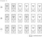
- FIG. 4 is a reference diagram for illustrating a method of controlling charging of the battery packs shown in FIG. 3 , according to an embodiment of the present invention.
- a control method of a battery system according to an embodiment of the present invention will be described in detail, taking the battery packs shown in FIG. 3 as an example.
- the battery packs included in the battery system shown in FIG. 3 are in a state of having different voltage values, respectively.
- battery packs #1 to #6 are in a state of having voltage values of 300 V, 305 V, 320 V, 328 V, 350 V, and 355 V, respectively.
- the battery control device 200 determines a first battery pack having the lowest voltage value among the plurality of battery packs. Also, the battery control device 200 selects a second battery pack whose voltage value difference from the first battery pack is equal to or less than a preset first threshold value. Thereafter, the battery control device 200 determines the first and second battery packs as a charging group.
- the battery control device 200 determines the battery pack #1 exhibiting the lowest voltage value (300V) among the battery packs #1 to #6, as the first battery pack.
- the battery control device 200 determines the battery pack #2 exhibiting a voltage value of 310V or lower, as the second battery pack, and determines the battery packs #1 and #2 as a charging group.
- the battery control device 200 controls the battery packs included in the charging group to be charged together up to a predefined target voltage.
- the target voltage may be defined as the lowest value among the voltage values of the respective battery packs not included in the charging group.
- the target voltage may be defined as 320V, which is the lowest value among the voltage values of the battery packs #3 to #6 not included in the charging group.
- the battery control device 200 controls the charging group (battery packs #1 and #2) to be charged up to the target voltage of 320V.
- the voltage of the battery pack may not reach the target voltage because the target voltage is a maximum voltage of a battery cell included in the battery pack.
- the battery packs #1 and #2 may be in a state of having a voltage value of 318V, which is equal to or lower than the target voltage of 320V.
- the battery control device 200 selects, among battery packs in which charging is not in progress, a third battery pack whose voltage value is equal to or greater than the voltage value of the charging group and voltage value difference from the charging group is equal to or less than a preset second threshold value. Thereafter, the battery control device 200 updates the charging group by adding the selected third battery pack to the charging group. Also, the battery control device 200 updates the currently set target voltage to the lowest value among the voltage values of the respective battery packs not included in the updated charging group.
- the battery control device 200 updates the charging group (battery packs #1 to #4) by selecting the battery packs #3 and #4 exhibiting voltage values of 318V or higher and 328V or lower among the battery packs #3 to #6, as the third battery pack, and including the battery packs #3 and #4 in the charging group.
- the battery control device 200 updates the currently set target voltage (320V) to 350V, which is the lowest value among the voltage values of the battery packs #5 and #6 not included in the updated charging group.
- the battery control device 200 controls the battery packs included in the updated charging group to be charged together up to the updated target voltage.
- the battery control device 200 controls the charging group (battery packs #1 to #4) to be charged up to the target voltage of 350V.
- the battery packs #1 to #4 may be in a state of having a voltage value of 348V, which is equal to or lower than the target voltage (350V).
- the battery control device 200 determines the battery packs #5 and #6 exhibiting voltage values of 348V or higher and 358V or lower among the battery packs #5 and #6, as the third battery pack, and updates the charging group (battery packs #1 to #6) by including the battery packs #5 and #6 in the charging group.
- the battery control device 200 may update the currently set target voltage to the highest value among the voltage values of the respective battery packs included in the updated charging group. For example, the battery control device 200 may update the currently set target voltage(350V) to 355V, which is the highest value among the voltage values of the battery packs #1 to #6 included in the updated charging group.
- FIG. 5 is a reference diagram for illustrating a method of updating a charging group of the battery packs shown in FIG. 3 , according to an embodiment of the present invention.
- the battery control device 200 determines or updates a charging group, based on measured voltages value of battery packs.
- a problem that some of the battery packs to be included in the charging group are missed may occur.
- the battery control device 200 selects, among the battery packs #3 to #6, a third battery pack whose voltage value is equal to or greater than the voltage value of the charging group and voltage value difference from the charging group is equal to or less than 10V (second threshold value), for update of the charging group.
- the voltage values of the battery packs #1 and #2 may be measured as 321V although the actual voltage values of the battery packs #1 and #2 are 318V.
- the battery control device 200 may add the battery pack #4 exhibiting a voltage value of 321V or higher and 331V or lower among the battery packs #3 to #6 to the charging group, and the battery pack #3 that should be included in the charging group may be missed.
- the charging group update process may be delayed after the charging of the battery packs #1 and #2 is completed.
- the voltages of the battery packs #1 and #2 may be increased to 319V by the minute charging current.
- the battery control device 200 may add the battery pack #4 exhibiting a voltage value of 319V or higher and 329V or lower among the battery packs #3 to #6 to the charging group, and the battery pack #3 that should be included in the charging group may be missed.
- the battery control device 200 may perform an operation according to an embodiment below so that a battery pack to be included in the charging group is not missed due to the measurement performance of the voltage measurement device and the data processing speed of the battery system.
- the battery control device 200 selects, among battery packs in which charging is not in progress, a fourth battery pack whose voltage value is less than the voltage value of the charging group and voltage value difference from the charging group is equal to or less than a preset third threshold value. Thereafter, the battery control device 200 adds the selected fourth battery pack to the charging group.
- the battery control device 200 adds the battery pack #4 exhibiting a voltage value of 321V or higher and 331V or lower among the battery packs #1 to #6 to the charging group. Also, when the third threshold value is defined as 5V, the battery control device 200 adds the battery pack #3 exhibiting a voltage value of 316V or higher and lower than 321V to the charging group. According to the present embodiment, both the battery packs #3 and #4 can be included in the charging group to be updated.
- the third threshold value may be defined based on at least one of a measurement error range of the voltage measurement device and a data processing speed of the battery control device.
- the third threshold value may be defined as a value equal to or greater than a maximum measurement error value of the voltage measurement device and equal to or less than the second threshold value. For example, when the second threshold value is 10V and the measurement error range of the voltage measurement device is -4 V to +4 V, the third threshold value may be defined as a value equal to or greater than 4 and equal to or less than 10.
- the third threshold value may be defined as a value equal to or greater than a maximum value of a rising voltage during data processing time for updating the charging group and equal to or less than the second threshold value.
- the maximum value of the rising voltage may be defined through a pre-test for the charging group update process. For example, when the second threshold value is 10V and the maximum value of the rising voltage during the data processing time for updating the charging group is 1V, the third threshold value may be defined as a value equal to or greater than 1 and equal to or less than 10.
- FIG. 6 is a block configuration diagram of a battery control device according to an embodiment of the present invention.
- a battery control device 600 is located in a battery system including a plurality of battery packs, and may include at least one processor 610, a memory 620 configured to store at least one command that is executed through the processor, and a transmitting/receiving device 630 connected to a network and configured to perform communication.
- the at least one command may include a command to collect voltage values for each of the plurality of battery packs; a command to determine a charging group by selecting one or more battery packs having a voltage value within a predefined threshold range; a command to control battery packs included in the charging group to be charged together to a predefined target voltage; and a command, when charging up to the target voltage is completed, to update the charging group by selecting, among battery packs in which charging is not in progress, a battery pack whose voltage value is within a predefined threshold range from a voltage value of the charging group.
- the command to determine the charging group may include a command to determine a first battery pack having the lowest voltage value among the plurality of battery packs; a command to select a second battery pack whose voltage value difference from the first battery pack is equal to or less than a preset first threshold value; and a command to determine the first and second battery packs as the charging group.
- the command to update the charging group may include a command to select, among the battery packs in which charging is not in progress, a third battery pack whose voltage value is equal to or greater than the voltage value of the charging group and voltage value difference from the charging group is equal to or less than a preset second threshold value; and a command to add the selected third battery pack to the charging group.
- the command to update the charging group may include a command to select, among the battery packs in which charging is not in progress, a fourth battery pack whose voltage value is less than the voltage value of the charging group and voltage value difference from the charging group is equal to or less than a preset third threshold value; and a command to add the selected fourth battery pack to the charging group.
- the third threshold value may be defined as a value equal to or greater than a maximum measurement error value of the voltage measurement device and equal to or less than the second threshold value.
- the third threshold value may be defined as a value equal to or greater than a maximum value of a rising voltage during data processing time for updating the charging group and equal to or less than the second threshold value.
- the battery control device 600 may further include an input interface device 640, an output interface device 650, a storage device 660, and the like.
- the respective components included in the battery control device 600 may be connected by a bus 670 and configured to perform communication with each other.
- the processor 610 may mean a central processing unit (CPU), a graphics processing unit (GPU), or a dedicated processor on which methods according to embodiments of the present invention are performed.
- the memory (or storage device) may be configured by at least one of a volatile storage medium and a non-volatile storage medium.
- the memory may be configured by at least one of a read only memory (ROM) and a random access memory (RAM).
- Operations according to embodiments of the present invention can be embodied as a computer-readable program or code on a computer-readable recording medium.
- the computer-readable recording medium includes all types of recording media in which data readable by a computer system is stored.
- the computer-readable recording medium may be distributed over computer systems connected through a network so that a computer-readable program or code may be stored and executed in a distributed manner.
- blocks or the device corresponds to operations of the method or characteristics of the operations of the method.
- aspects of the present invention described above in the context of a method may be described using blocks or items corresponding thereto or characteristics of a device corresponding thereto.
- Some or all of the operations of the method may be performed, for example, by (or using) a hardware device such as a microprocessor, a programmable computer or an electronic circuit. In some embodiments, one or more of most important operations of the method may be performed by such a device.
Landscapes
- Engineering & Computer Science (AREA)
- Power Engineering (AREA)
- Manufacturing & Machinery (AREA)
- Chemical & Material Sciences (AREA)
- Chemical Kinetics & Catalysis (AREA)
- Electrochemistry (AREA)
- General Chemical & Material Sciences (AREA)
- Physics & Mathematics (AREA)
- General Physics & Mathematics (AREA)
- Microelectronics & Electronic Packaging (AREA)
- Charge And Discharge Circuits For Batteries Or The Like (AREA)
- Secondary Cells (AREA)
Abstract
Description
- This application claims priority to and the benefit of
Korean Patent Application No. 10-2022-0082964 filed in the Korean Intellectual Property Office on July 6, 2022 - The present invention relates to a battery system and a control method thereof, and more particularly, to a battery system, a battery control device, and a control method of a battery system for sequentially charging batteries having different voltages.
- A secondary battery is a battery that can be reused through charging even after being discharged, can be used as an energy source for a small device such as a mobile phone, a tablet PC and a vacuum cleaner, and is also used as an energy source for mid-size and large-size devices such as an automobile and an ESS (Energy Storage System) for a smart grid.
- The secondary battery is applied to a system in a form of an assembly such as a battery module in which a plurality of battery cells are connected in series and parallel or a battery pack in which battery modules are connected in series and parallel, depending on system requirements. In the case of mid-size and large-size devices such as an electric vehicle, a high-capacity battery system in which a plurality of battery packs are connected in parallel may be applied so as to satisfy a required capacity of the corresponding device.
- In the high-capacity battery system in which the plurality of battery packs are configured as such, when a new battery pack is additionally installed to expand a capacity or when an abnormality occurs in some of the battery packs, high voltage differences may occur among the battery packs. At this time, when the battery packs are charged using a general charging method, charging efficiency may be lowered, a battery lifetime may be reduced, and some components of the battery system may be damaged.
- Accordingly, there is a need for an appropriate control technique for charging battery packs exhibiting high voltage differences.
- The present invention has been made in an effort to provide a battery system for sequentially charging batteries.
- The present invention has also been made in an effort to provide a control method of the battery system.
- The present invention has also been made in an effort to provide a battery control device for controlling an operation of the battery system.
- An exemplary embodiment of the present invention provides a battery system including a plurality of battery packs; and a battery control device configured to collect voltage values for each of the plurality of battery packs and to control charging of the plurality of battery packs, based on the collected voltage values.
- The battery control device may be configured to determine a charging group by selecting one or more battery packs having a voltage value within a predefined threshold range, and to control the battery packs included in the charging group to be charged together up to a predefined target voltage. Here, the battery control device may be configured, when charging up to the target voltage is completed, to update the charging group by selecting, among battery packs in which charging is not in progress, a battery pack whose voltage value is within a predefined threshold range from a voltage value of the charging group.
- The battery control device may be configured to determine a first battery pack having the lowest voltage value among the plurality of battery packs, to select a second battery pack whose voltage value difference from the first battery pack is equal to or less than a preset first threshold value, and to determine the first and second battery packs as the charging group.
- The battery control device may be configured, when the charging group is charged up to the target voltage, to update the charging group by selecting, among the battery packs in which charging is not in progress, a third battery pack whose voltage value is equal to or greater than the voltage value of the charging group and voltage value difference from the charging group is equal to or less than a preset second threshold value and adding the selected third battery pack to the charging group.
- The battery control device may be configured to select, among the battery packs in which charging is not in progress, a fourth battery pack whose voltage value is less than the voltage value of the charging group and voltage value difference from the charging group is equal to or less than a preset third threshold value and to add the selected fourth battery pack to the charging group.
- The third threshold value may be defined based on at least one of a measurement error range of a voltage measurement device configured to measure a voltage value of a battery pack and a data processing speed of the battery control device.
- The third threshold value may be defined as a value equal to or greater than a maximum measurement error value of the voltage measurement device and equal to or less than the second threshold value.
- The third threshold may be defined as a value equal to or greater than a maximum value of a rising voltage during data processing time for updating the charging group and equal to or less than the second threshold value.
- Another exemplary embodiment of the present invention provides a control method of a battery system including a plurality of battery packs, and a battery control device, the control method including collecting, by the battery control device, voltage values for each of the plurality of battery packs; determining, by the battery control device, a charging group by selecting one or more battery packs having a voltage value within a predefined threshold range; controlling, by the battery control device, the battery packs included in the charging group to be charged together up to a predefined target voltage; and when charging up to the target voltage is completed, updating, by the battery control device, the charging group by selecting, among battery packs in which charging is not in progress, a battery pack whose voltage value is within a predefined threshold range from a voltage value of the charging group.
- The determining of the charging group may include determining a first battery pack having the lowest voltage value among the plurality of battery packs; selecting a second battery pack whose voltage value difference from the first battery pack is equal to or less than a preset first threshold value; and determining the first and second battery packs as the charging group.
- The updating of the charging group may include selecting, among the battery packs in which charging is not in progress, a third battery pack whose voltage value is equal to or greater than the voltage value of the charging group and voltage value difference from the charging group is equal to or less than a preset second threshold value; and adding the selected third battery pack to the charging group.
- The updating of the charging group may include selecting, among the battery packs in which charging is not in progress, a fourth battery pack whose voltage value is less than the voltage value of the charging group and voltage value difference from the charging group is equal to or less than a preset third threshold value; and adding the selected fourth battery pack to the charging group.
- The third threshold value may be defined as a value equal to or greater than a maximum measurement error value of a voltage measurement device and equal to or less than the second threshold value.
- The third threshold may be defined as a value equal to or greater than a maximum value of a rising voltage during data processing time for updating the charging group and equal to or less than the second threshold value.
- Still another exemplary embodiment of the present invention provides a battery control device located in a battery system including a plurality of battery packs, the control device including at least one processor; and a memory configured to store at least one command that is executed by the at least one processor.
- Here, the at least one command may include a command to collect voltage values for each of the plurality of battery packs; a command to determine a charging group by selecting one or more battery packs having a voltage value within a predefined threshold range; a command to control battery packs included in the charging group to be charged together to a predefined target voltage; and a command, when charging up to the target voltage is completed, to update the charging group by selecting, among battery packs in which charging is not in progress, a battery pack whose voltage value is within a predefined threshold range from a voltage value of the charging group.
- The command to determine the charging group may include a command to determine a first battery pack having the lowest voltage value among the plurality of battery packs; a command to select a second battery pack whose voltage value difference from the first battery pack is equal to or less than a preset first threshold value; and a command to determine the first and second battery packs as the charging group.
- The command to update the charging group may include a command to select, among the battery packs in which charging is not in progress, a third battery pack whose voltage value is equal to or greater than the voltage value of the charging group and voltage value difference from the charging group is equal to or less than a preset second threshold value; and a command to add the selected third battery pack to the charging group.
- The command to update the charging group may include a command to select, among the battery packs in which charging is not in progress, a fourth battery pack whose voltage value is less than the voltage value of the charging group and voltage value difference from the charging group is equal to or less than a preset third threshold value; and a command to add the selected fourth battery pack to the charging group.
- The third threshold value may be defined as a value equal to or greater than a maximum measurement error value of a voltage measurement device and equal to or less than the second threshold value.
- The third threshold may be defined as a value equal to or greater than a maximum value of a rising voltage during data processing time for updating the charging group and equal to or less than the second threshold value.
- According to exemplary embodiments of the present invention, it is possible to effectively charge the battery packs exhibiting high voltage differences by grouping and sequentially charging battery packs having a voltage value within a certain range.
-
-
FIG. 1 is a block configuration diagram for illustrating a battery system according to an embodiment of the present invention. -
FIG. 2 is an operation flowchart of a control method of a battery system according to an embodiment of the present invention. -
FIG. 3 shows an example of battery packs exhibiting voltage differences. -
FIG. 4 is a reference diagram for illustrating a method of controlling charging of the battery packs shown inFIG. 3 , according to an embodiment of the present invention. -
FIG. 5 is a reference diagram for illustrating a method of updating a charging group of the battery packs shown inFIG. 3 , according to an embodiment of the present invention. -
FIG. 6 is a block configuration diagram of a battery control device according to an embodiment of the present invention. - 100: battery pack
- 200: battery control device
- 600: battery control device
- The present invention may be modified in various forms and have various embodiments, and specific embodiments thereof are shown by way of example in the drawings and will be described in detail below. It should be understood, however, that there is no intent to limit the present invention to the specific embodiments, but on the contrary, the present invention is to cover all modifications, equivalents, and alternatives falling within the spirit and technical scope of the present invention. Like reference numerals refer to like elements throughout the description of the figures.
- It will be understood that, although the terms such as first, second, A, B, and the like may be used herein to describe various elements, these elements should not be limited by these terms. These terms are only used to distinguish one element from another. For example, a first element could be termed a second element, and, similarly, a second element could be termed a first element, without departing from the scope of the present invention. As used herein, the term "and/or" includes combinations of a plurality of associated listed items or any of the plurality of associated listed items.
- It will be understood that when an element is referred to as being "coupled" or "connected" to another element, it can be directly coupled or connected to the other element or an intervening element may be present. In contrast, when an element is referred to as being "directly coupled" or "directly connected" to another element, there is no intervening element present.
- The terms used herein is for the purpose of describing specific embodiments only and are not intended to limit the present invention. As used herein, the singular forms "a", "an" and "the" are intended to include the plural forms as well, unless the context clearly indicates otherwise. It will be further understood that the terms "comprises", "comprising", "includes", "including" and/or "having", when used herein, specify the presence of stated features, integers, steps, operations, constitutional elements, components and/or combinations thereof, but do not preclude the presence or addition of one or more other features, integers, steps, operations, constitutional elements, components, and/or combinations thereof.
- Unless otherwise defined, all terms used herein, including technical and scientific terms, have the same meanings as commonly understood by one skilled in the art to which the present invention belongs. It will be further understood that terms, such as those defined in commonly used dictionaries, should be interpreted as having meanings that are consistent with their meanings in the context of the relevant art and will not be interpreted in an idealized or overly formal sense unless expressly so defined herein.
- Some terms used herein are defined as follows.
- A battery cell is a minimum unit that serves to store power, and a battery module refers to an assembly in which a plurality of battery cells are electrically connected.
- A battery pack or battery rack refers to a system with a minimum single structure that can be monitored and controlled through a battery management system (BMS) by electrically connecting module units set by a battery manufacturer, and may include several battery modules and one battery protection unit (BPU) or protection device.
- A battery bank may refer to an assembly group of large-scale battery rack systems configured by connecting a plurality of battery racks in parallel. Monitoring and control of a rack BMS (RBMS) of a battery rack unit can be performed through the BMS of a battery bank unit.
- A battery assembly includes a plurality of electrically connected battery cells, and refers to an assembly that functions as a power supply source by being applied to a specific system or device. Here, the battery assembly may mean a battery module, a battery pack, a battery rack, a battery bank or the like, but the scope of the present invention is not limited to these entities.
- A state of charge (SOC) is a current charged state of a battery expressed as a percentage [%], and a state of health (SOH) is a current remaining state of a battery expressed as a percentage [%].
- A nominal capacity (nominal capa.) may mean a set capacity [Ah] of a battery set by a battery manufacturer during development.
- Hereinafter, preferred embodiments of the present invention will be described in detail with reference to the drawings.
-
FIG. 1 is a block configuration diagram for illustrating a battery system according to an embodiment of the present invention. - Referring to
FIG. 1 , the battery system includes a battery assembly including a plurality of battery packs 100 and abattery control device 200. - The plurality of battery packs 100 may be connected to each other in parallel to constitute a battery assembly.
- The battery system according to an embodiment of the present invention may be included and implemented in an electric vehicle, but the scope of the present invention is not limited to the entity. That is, the battery system according to an embodiment of the present invention may be applied to a device having a plurality of battery packs and may be configured to control charging of the battery packs exhibiting voltage differences through a control operation described below.
- The
battery control device 200 may be included and implemented in a BMS located inside the battery system. - The
battery control device 200 may be configured to collect voltage values for each of the plurality of battery packs 100 and to control charging of the plurality of battery packs, based on the collected voltage values. Here, thebattery control device 200 may be configured to control charging of each battery pack in a manner of controlling a charging circuit connected to each of the plurality of battery packs 100 (for example, ON/OFF control of a relay circuit). - Hereinafter, operations of the battery system and the
battery control device 200 according to an embodiment of the present invention will be described in detail with reference toFIGS. 2 to 5 . -
FIG. 2 is an operation flowchart of a control method of a battery system according to an embodiment of the present invention. - The
battery control device 200 collects voltage values for each of a plurality of battery packs. Here, thebattery control device 200 may collect the voltage values of the battery packs for each preset unit time (for example, 1 second) or predefined time point (for example, determination or update time point of a charging group). - The
battery control device 200 determines a charging group including some of the plurality of battery packs, based on the voltage values for each of the plurality of battery packs (S210). - Here, the
battery control device 200 may select one or more battery packs having a voltage value within a predefined threshold range and determine the selected battery packs as a charging group. Meanwhile, when the selected battery pack is a battery pack determined as being in an abnormal state, the battery pack in the abnormal state may be excluded from the charging group. - Thereafter, the
battery control device 200 controls the battery packs included in the charging group determined in S210 to be charged together up to a predefined target voltage (S220). Here, the target voltage may be defined as the lowest value among the voltage values of the respective battery packs not included in the charging group. - When the battery packs included in the charging group are charged up to the target voltage, the
battery control device 200 checks whether charging of all the battery packs is completed (S230). - When all the battery packs are not completely charged (NO in S230), the
battery control device 200 updates the charging group determined in S210 and the target voltage (S240). - Here, the
battery control device 200 may update the charging group by selecting a battery pack whose voltage value is within a predefined threshold range from a voltage value of the charging group among battery packs in which charging is not in progress (i.e., battery packs not included in the charging group) and including the selected battery pack in the charging group. Meanwhile, when the selected battery pack is a battery pack determined as being in an abnormal state, the battery pack in the abnormal state may be excluded from the charging group. In addition, thebattery control device 200 may update the currently set target voltage to the lowest value among the voltage values of the respective battery packs not included in the updated charging group. - Thereafter, the
battery control device 200 controls the battery packs included in the updated charging group to be charged together up to the updated target voltage (S220). - As shown in
FIG. 2 , the process of sequentially updating and charging the charging group may be repeatedly performed until charging of all the battery packs is completed (YES in S230). -
FIG. 3 shows an example of battery packs exhibiting voltage differences, andFIG. 4 is a reference diagram for illustrating a method of controlling charging of the battery packs shown inFIG. 3 , according to an embodiment of the present invention. Hereinafter, a control method of a battery system according to an embodiment of the present invention will be described in detail, taking the battery packs shown inFIG. 3 as an example. - The battery packs included in the battery system shown in
FIG. 3 are in a state of having different voltage values, respectively. As shown inFIG. 3 , battery packs #1 to #6 are in a state of having voltage values of 300 V, 305 V, 320 V, 328 V, 350 V, and 355 V, respectively. - The
battery control device 200 determines a first battery pack having the lowest voltage value among the plurality of battery packs. Also, thebattery control device 200 selects a second battery pack whose voltage value difference from the first battery pack is equal to or less than a preset first threshold value. Thereafter, thebattery control device 200 determines the first and second battery packs as a charging group. - For example, referring to
FIG. 4(A) , thebattery control device 200 determines thebattery pack # 1 exhibiting the lowest voltage value (300V) among the battery packs #1 to #6, as the first battery pack. When the first threshold value is defined as 10V, thebattery control device 200 determines thebattery pack # 2 exhibiting a voltage value of 310V or lower, as the second battery pack, and determines the battery packs #1 and #2 as a charging group. - The
battery control device 200 controls the battery packs included in the charging group to be charged together up to a predefined target voltage. Here, the target voltage may be defined as the lowest value among the voltage values of the respective battery packs not included in the charging group. - For example, referring to
FIG. 4(A) , the target voltage may be defined as 320V, which is the lowest value among the voltage values of the battery packs #3 to #6 not included in the charging group. Thebattery control device 200 controls the charging group (battery packs #1 and #2) to be charged up to the target voltage of 320V. - On the other hand, even when the battery pack is charged up to the set target voltage, the voltage of the battery pack may not reach the target voltage because the target voltage is a maximum voltage of a battery cell included in the battery pack. For example, as shown in
FIG. 4(B) , when the charging of the battery packs #1 and #2 up to the target voltage of 320V is completed, the battery packs #1 and #2 may be in a state of having a voltage value of 318V, which is equal to or lower than the target voltage of 320V. - When the charging group is charged up to the target voltage, the
battery control device 200 selects, among battery packs in which charging is not in progress, a third battery pack whose voltage value is equal to or greater than the voltage value of the charging group and voltage value difference from the charging group is equal to or less than a preset second threshold value. Thereafter, thebattery control device 200 updates the charging group by adding the selected third battery pack to the charging group. Also, thebattery control device 200 updates the currently set target voltage to the lowest value among the voltage values of the respective battery packs not included in the updated charging group. - For example, when the second threshold value is defined as 10V, as shown in
FIG. 4(B) , thebattery control device 200 updates the charging group (battery packs #1 to #4) by selecting the battery packs #3 and #4 exhibiting voltage values of 318V or higher and 328V or lower among the battery packs #3 to #6, as the third battery pack, and including the battery packs #3 and #4 in the charging group. In addition, thebattery control device 200 updates the currently set target voltage (320V) to 350V, which is the lowest value among the voltage values of the battery packs #5 and #6 not included in the updated charging group. - The
battery control device 200 controls the battery packs included in the updated charging group to be charged together up to the updated target voltage. - For example, referring to
FIG. 4(C) , thebattery control device 200 controls the charging group (battery packs #1 to #4) to be charged up to the target voltage of 350V. Here, when the charging of the battery packs #1 to #4 up to the target voltage (350V) is completed, the battery packs #1 to #4 may be in a state of having a voltage value of 348V, which is equal to or lower than the target voltage (350V). - After completion of the charging up to the target voltage, the
battery control device 200 determines the battery packs #5 and #6 exhibiting voltage values of 348V or higher and 358V or lower among the battery packs #5 and #6, as the third battery pack, and updates the charging group (battery packs #1 to #6) by including the battery packs #5 and #6 in the charging group. - When there is no battery pack not included in the updated charging group, the
battery control device 200 may update the currently set target voltage to the highest value among the voltage values of the respective battery packs included in the updated charging group. For example, thebattery control device 200 may update the currently set target voltage(350V) to 355V, which is the highest value among the voltage values of the battery packs #1 to #6 included in the updated charging group. - When the charging up to the updated target voltage (355V) is completed, the charging of all the battery packs is completed, and therefore, the charging process ends.
-
FIG. 5 is a reference diagram for illustrating a method of updating a charging group of the battery packs shown inFIG. 3 , according to an embodiment of the present invention. - The
battery control device 200 according to an embodiment of the present invention determines or updates a charging group, based on measured voltages value of battery packs. Here, when the measurement accuracy of a voltage measurement device is low or when a data processing speed of the system is slow, a problem that some of the battery packs to be included in the charging group are missed may occur. - For example, in
FIG. 5(B) , when the charging of the charging group (battery packs #1 and #2) is completed, thebattery control device 200 selects, among the battery packs #3 to #6, a third battery pack whose voltage value is equal to or greater than the voltage value of the charging group and voltage value difference from the charging group is equal to or less than 10V (second threshold value), for update of the charging group. - Here, when the voltage measurement device has a certain measurement error range (for example, -4V to +4V), the voltage values of the battery packs #1 and #2 may be measured as 321V although the actual voltage values of the battery packs #1 and #2 are 318V. In this case, the
battery control device 200 may add thebattery pack # 4 exhibiting a voltage value of 321V or higher and 331V or lower among the battery packs #3 to #6 to the charging group, and thebattery pack # 3 that should be included in the charging group may be missed. - Also, when the battery system is implemented as a low-performance system, the charging group update process may be delayed after the charging of the battery packs #1 and #2 is completed. In this case, during the data processing time for updating the charging group, the voltages of the battery packs #1 and #2 may be increased to 319V by the minute charging current. In this case, the
battery control device 200 may add thebattery pack # 4 exhibiting a voltage value of 319V or higher and 329V or lower among the battery packs #3 to #6 to the charging group, and thebattery pack # 3 that should be included in the charging group may be missed. - When updating the charging group, the
battery control device 200 may perform an operation according to an embodiment below so that a battery pack to be included in the charging group is not missed due to the measurement performance of the voltage measurement device and the data processing speed of the battery system. - When the charging group is charged up to the target voltage, the
battery control device 200 selects, among battery packs in which charging is not in progress, a fourth battery pack whose voltage value is less than the voltage value of the charging group and voltage value difference from the charging group is equal to or less than a preset third threshold value. Thereafter, thebattery control device 200 adds the selected fourth battery pack to the charging group. - For example, in
FIG. 5(B) , when the voltages of the battery packs #1 and #2 are measured as 321V after the charging of the battery packs #1 and #2 is completed, thebattery control device 200 adds thebattery pack # 4 exhibiting a voltage value of 321V or higher and 331V or lower among the battery packs #1 to #6 to the charging group. Also, when the third threshold value is defined as 5V, thebattery control device 200 adds thebattery pack # 3 exhibiting a voltage value of 316V or higher and lower than 321V to the charging group. According to the present embodiment, both the battery packs #3 and #4 can be included in the charging group to be updated. - The third threshold value may be defined based on at least one of a measurement error range of the voltage measurement device and a data processing speed of the battery control device.
- In an embodiment, the third threshold value may be defined as a value equal to or greater than a maximum measurement error value of the voltage measurement device and equal to or less than the second threshold value. For example, when the second threshold value is 10V and the measurement error range of the voltage measurement device is -4 V to +4 V, the third threshold value may be defined as a value equal to or greater than 4 and equal to or less than 10.
- In another embodiment, the third threshold value may be defined as a value equal to or greater than a maximum value of a rising voltage during data processing time for updating the charging group and equal to or less than the second threshold value. Here, the maximum value of the rising voltage may be defined through a pre-test for the charging group update process. For example, when the second threshold value is 10V and the maximum value of the rising voltage during the data processing time for updating the charging group is 1V, the third threshold value may be defined as a value equal to or greater than 1 and equal to or less than 10.
-
FIG. 6 is a block configuration diagram of a battery control device according to an embodiment of the present invention. - A
battery control device 600 according to an embodiment of the present invention is located in a battery system including a plurality of battery packs, and may include at least oneprocessor 610, amemory 620 configured to store at least one command that is executed through the processor, and a transmitting/receiving device 630 connected to a network and configured to perform communication. - The at least one command may include a command to collect voltage values for each of the plurality of battery packs; a command to determine a charging group by selecting one or more battery packs having a voltage value within a predefined threshold range; a command to control battery packs included in the charging group to be charged together to a predefined target voltage; and a command, when charging up to the target voltage is completed, to update the charging group by selecting, among battery packs in which charging is not in progress, a battery pack whose voltage value is within a predefined threshold range from a voltage value of the charging group.
- The command to determine the charging group may include a command to determine a first battery pack having the lowest voltage value among the plurality of battery packs; a command to select a second battery pack whose voltage value difference from the first battery pack is equal to or less than a preset first threshold value; and a command to determine the first and second battery packs as the charging group.
- The command to update the charging group may include a command to select, among the battery packs in which charging is not in progress, a third battery pack whose voltage value is equal to or greater than the voltage value of the charging group and voltage value difference from the charging group is equal to or less than a preset second threshold value; and a command to add the selected third battery pack to the charging group.
- The command to update the charging group may include a command to select, among the battery packs in which charging is not in progress, a fourth battery pack whose voltage value is less than the voltage value of the charging group and voltage value difference from the charging group is equal to or less than a preset third threshold value; and a command to add the selected fourth battery pack to the charging group.
- The third threshold value may be defined as a value equal to or greater than a maximum measurement error value of the voltage measurement device and equal to or less than the second threshold value.
- The third threshold value may be defined as a value equal to or greater than a maximum value of a rising voltage during data processing time for updating the charging group and equal to or less than the second threshold value.
- The
battery control device 600 may further include aninput interface device 640, anoutput interface device 650, astorage device 660, and the like. The respective components included in thebattery control device 600 may be connected by abus 670 and configured to perform communication with each other. - Here, the
processor 610 may mean a central processing unit (CPU), a graphics processing unit (GPU), or a dedicated processor on which methods according to embodiments of the present invention are performed. The memory (or storage device) may be configured by at least one of a volatile storage medium and a non-volatile storage medium. For example, the memory may be configured by at least one of a read only memory (ROM) and a random access memory (RAM). - Operations according to embodiments of the present invention can be embodied as a computer-readable program or code on a computer-readable recording medium. The computer-readable recording medium includes all types of recording media in which data readable by a computer system is stored. In addition, the computer-readable recording medium may be distributed over computer systems connected through a network so that a computer-readable program or code may be stored and executed in a distributed manner.
- Some aspects of the present invention have been described above in the context of a device but may be described using a method corresponding thereto. Here, blocks or the device corresponds to operations of the method or characteristics of the operations of the method. Similarly, aspects of the present invention described above in the context of a method may be described using blocks or items corresponding thereto or characteristics of a device corresponding thereto. Some or all of the operations of the method may be performed, for example, by (or using) a hardware device such as a microprocessor, a programmable computer or an electronic circuit. In some embodiments, one or more of most important operations of the method may be performed by such a device.
- While the present invention has been described above with reference to embodiments thereof, it would be understood by one skilled in the art that various changes and modifications can be made in the present invention without departing from the spirit and scope of the present invention defined in the following claims.
Claims (19)
- A battery system comprising:a plurality of battery packs; anda battery control device configured to collect voltage values for each of the plurality of battery packs and to control charging of the plurality of battery packs, based on the collected voltage values,wherein the battery control device is configured:
to determine a charging group by selecting one or more battery packs having a voltage value within a predefined threshold range, to control the battery packs included in the charging group to be charged together up to a predefined target voltage, and when charging up to the target voltage is completed, to update the charging group by selecting, among battery packs in which charging is not in progress, a battery pack whose voltage value is within a predefined threshold range from a voltage value of the charging group. - The battery system of claim 1, wherein the battery control device is configured to determine a first battery pack having the lowest voltage value among the plurality of battery packs, to select a second battery pack whose voltage value difference from the first battery pack is equal to or less than a preset first threshold value, and to determine the first and second battery packs as the charging group.
- The battery system of claim 1, wherein the battery control device is configured, when the charging group is charged up to the target voltage, to update the charging group by selecting, among the battery packs in which charging is not in progress, a third battery pack whose voltage value is equal to or greater than the voltage value of the charging group and voltage value difference from the charging group is equal to or less than a preset second threshold value and adding the selected third battery pack to the charging group.
- The battery system of claim 3, wherein the battery control device is configured to select, among the battery packs in which charging is not in progress, a fourth battery pack whose voltage value is less than the voltage value of the charging group and voltage value difference from the charging group is equal to or less than a preset third threshold value and to add the selected fourth battery pack to the charging group.
- The battery system of claim 4, wherein the third threshold value is defined based on at least one of a measurement error range of a voltage measurement device configured to measure a voltage value of a battery pack and a data processing speed of the battery control device.
- The battery system of claim 5, wherein the third threshold value is defined as a value equal to or greater than a maximum measurement error value of the voltage measurement device and equal to or less than the second threshold value.
- The battery system of claim 5, wherein the third threshold value is defined as a value equal to or greater than a maximum value of a rising voltage during data processing time for updating the charging group and equal to or less than the second threshold value.
- A control method of a battery system comprising a plurality of battery packs, and a battery control device, the control method comprising:collecting, by the battery control device, voltage values for each of the plurality of battery packs;determining, by the battery control device, a charging group by selecting one or more battery packs having a voltage value within a predefined threshold range;controlling, by the battery control device, the battery packs included in the charging group to be charged together up to a predefined target voltage; andwhen charging up to the target voltage is completed, updating, by the battery control device, the charging group by selecting, among battery packs in which charging is not in progress, a battery pack whose voltage value is within a predefined threshold range from a voltage value of the charging group.
- The control method of claim 8, wherein the determining of the charging group comprises:determining a first battery pack having the lowest voltage value among the plurality of battery packs;selecting a second battery pack whose voltage value difference from the first battery pack is equal to or less than a preset first threshold value; anddetermining the first and second battery packs as the charging group.
- The control method of claim 8, wherein the updating of the charging group comprises:selecting, among the battery packs in which charging is not in progress, a third battery pack whose voltage value is equal to or greater than the voltage value of the charging group and voltage value difference from the charging group is equal to or less than a preset second threshold value; andadding the selected third battery pack to the charging group.
- The control method of claim 10, wherein the updating of the charging group comprises:selecting, among the battery packs in which charging is not in progress, a fourth battery pack whose voltage value is less than the voltage value of the charging group and voltage value difference from the charging group is equal to or less than a preset third threshold value; andadding the selected fourth battery pack to the charging group.
- The control method of claim 11, wherein the third threshold value is defined as a value equal to or greater than a maximum measurement error value of a voltage measurement device and equal to or less than the second threshold value.
- The control method of claim 11, wherein the third threshold value is defined as a value equal to or greater than a maximum value of a rising voltage during data processing time for updating the charging group and equal to or less than the second threshold value.
- A battery control device located in a battery system comprising a plurality of battery packs, the battery control device comprising:at least one processor; anda memory configured to store at least one command that is executed by the at least one processor,wherein the at least one command comprises:a command to collect voltage values for each of the plurality of battery packs;a command to determine a charging group by selecting one or more battery packs having a voltage value within a predefined threshold range;a command to control battery packs included in the charging group to be charged together to a predefined target voltage; anda command, when charging up to the target voltage is completed, to update the charging group by selecting, among battery packs in which charging is not in progress, a battery pack whose voltage value is within a predefined threshold range from a voltage value of the charging group.
- The battery control device of claim 14, wherein the command to determine the charging group comprises:a command to determine a first battery pack having the lowest voltage value among the plurality of battery packs;a command to select a second battery pack whose voltage value difference from the first battery pack is equal to or less than a preset first threshold value; anda command to determine the first and second battery packs as the charging group.
- The battery control device of claim 14, wherein the command to update the charging group comprises:a command to select, among the battery packs in which charging is not in progress, a third battery pack whose voltage value is equal to or greater than the voltage value of the charging group and voltage value difference from the charging group is equal to or less than a preset second threshold value; anda command to add the selected third battery pack to the charging group.
- The battery control device of claim 16, wherein the command to update the charging group comprises:a command to select, among the battery packs in which charging is not in progress, a fourth battery pack whose voltage value is less than the voltage value of the charging group and voltage value difference from the charging group is equal to or less than a preset third threshold value; anda command to add the selected fourth battery pack to the charging group.
- The battery control device of claim 17, wherein the third threshold value is defined as a value equal to or greater than a maximum measurement error value of a voltage measurement device and equal to or less than the second threshold value.
- The battery control device of claim 17, wherein the third threshold value is defined as a value equal to or greater than a maximum value of a rising voltage during data processing time for updating the charging group and equal to or less than the second threshold value.
Applications Claiming Priority (2)
| Application Number | Priority Date | Filing Date | Title |
|---|---|---|---|
| KR1020220082964A KR20240006204A (en) | 2022-07-06 | 2022-07-06 | Battery system for sequentially charging batteries and controlling method thereof |
| PCT/KR2023/008702 WO2024010254A1 (en) | 2022-07-06 | 2023-06-22 | Battery system for sequential charging of batteries and control method thereof |
Publications (2)
| Publication Number | Publication Date |
|---|---|
| EP4462633A1 true EP4462633A1 (en) | 2024-11-13 |
| EP4462633A4 EP4462633A4 (en) | 2025-11-05 |
Family
ID=89453709
Family Applications (1)
| Application Number | Title | Priority Date | Filing Date |
|---|---|---|---|
| EP23835721.4A Pending EP4462633A4 (en) | 2022-07-06 | 2023-06-22 | BATTERY SYSTEM FOR SEQUENTIAL CHARGING OF BATTERIES AND CONTROL METHOD FOR THIS |
Country Status (6)
| Country | Link |
|---|---|
| US (1) | US20250239866A1 (en) |
| EP (1) | EP4462633A4 (en) |
| JP (1) | JP7673894B2 (en) |
| KR (1) | KR20240006204A (en) |
| CN (1) | CN118556354A (en) |
| WO (1) | WO2024010254A1 (en) |
Family Cites Families (16)
| Publication number | Priority date | Publication date | Assignee | Title |
|---|---|---|---|---|
| JP2001136669A (en) * | 1999-11-01 | 2001-05-18 | Toyota Central Res & Dev Lab Inc | Storage device |
| JP5096817B2 (en) * | 2007-07-10 | 2012-12-12 | プライムアースEvエナジー株式会社 | Manufacturing method of reconfigurable battery pack |
| JP5593849B2 (en) * | 2009-06-12 | 2014-09-24 | 日産自動車株式会社 | Battery monitoring device |
| KR101570420B1 (en) * | 2009-08-10 | 2015-11-20 | 엘지전자 주식회사 | Battery controlling apparatus for mobile vehicle and method thereof |
| KR101207049B1 (en) * | 2010-11-25 | 2012-11-30 | 중앙대학교 산학협력단 | Charging apparatus and method for portable electronic device |
| CN103023082A (en) * | 2011-09-27 | 2013-04-03 | 深圳富泰宏精密工业有限公司 | Battery charge and discharge control system and battery charge and discharge control method |
| JP2014057398A (en) * | 2012-09-11 | 2014-03-27 | Panasonic Corp | Storage battery management apparatus and storage battery management method |
| JP6201763B2 (en) * | 2013-01-22 | 2017-09-27 | 株式会社Gsユアサ | Storage unit connection information acquisition device |
| KR101610927B1 (en) | 2014-12-15 | 2016-04-08 | 현대오트론 주식회사 | Apparatus and method for battery cell balancing |
| KR102677447B1 (en) * | 2016-01-21 | 2024-06-21 | 삼성전자주식회사 | Apparatus and Method for battery pack charging |
| EP3197006B1 (en) * | 2016-01-21 | 2021-06-16 | Samsung Electronics Co., Ltd. | Apparatus and method of charging battery pack |
| KR102248227B1 (en) * | 2019-01-10 | 2021-05-03 | 주식회사 엘지화학 | Apparatus and method for balancing battery and battery pack including the same |
| ES2983185T3 (en) * | 2020-07-01 | 2024-10-22 | Vestas Wind Sys As | Adaptive energy storage augmentation for load response |
| US11710975B2 (en) * | 2020-07-30 | 2023-07-25 | Denso International America, Inc. | Battery charging systems and methods |
| KR102923312B1 (en) | 2020-12-10 | 2026-02-05 | 삼성디스플레이 주식회사 | Display device and method of manufacturing the display device |
| JP7736632B2 (en) * | 2022-05-30 | 2025-09-09 | 株式会社日立製作所 | Railway vehicle battery system and control method thereof |
-
2022
- 2022-07-06 KR KR1020220082964A patent/KR20240006204A/en active Pending
-
2023
- 2023-06-22 US US18/838,728 patent/US20250239866A1/en active Pending
- 2023-06-22 JP JP2024543836A patent/JP7673894B2/en active Active
- 2023-06-22 WO PCT/KR2023/008702 patent/WO2024010254A1/en not_active Ceased
- 2023-06-22 EP EP23835721.4A patent/EP4462633A4/en active Pending
- 2023-06-22 CN CN202380019347.8A patent/CN118556354A/en active Pending
Also Published As
| Publication number | Publication date |
|---|---|
| US20250239866A1 (en) | 2025-07-24 |
| EP4462633A4 (en) | 2025-11-05 |
| JP7673894B2 (en) | 2025-05-09 |
| CN118556354A (en) | 2024-08-27 |
| JP2025503934A (en) | 2025-02-06 |
| WO2024010254A1 (en) | 2024-01-11 |
| KR20240006204A (en) | 2024-01-15 |
Similar Documents
| Publication | Publication Date | Title |
|---|---|---|
| EP3444921B1 (en) | Charging control apparatus and method capable of energy saving and quick cell balancing | |
| US12449485B2 (en) | Battery management apparatus and method | |
| EP4446760A1 (en) | Apparatus for calculating depth of charge of battery, and operation method thereof | |
| US11831716B2 (en) | System and method for communication between BMSs | |
| EP4446764A1 (en) | Battery state management device and operation method thereof | |
| US12566217B2 (en) | Apparatus and method for estimating battery cell capacity | |
| EP4518089A1 (en) | Battery charging control apparatus and method, and battery system comprising same | |
| EP4369550A1 (en) | Charging method, charging apparatus and computer-readable storage medium | |
| KR101745633B1 (en) | Apparatus for Cell Balancing by Connecting Reference Battery in Consecutive Order and Method thereof | |
| EP4462633A1 (en) | Battery system for sequential charging of batteries and control method thereof | |
| CN116520159B (en) | Method and electronic device for determining charging cut-off voltage of lithium-ion battery | |
| EP4404417B1 (en) | BATTERY CONTROL SYSTEM AND METHOD FOR MANAGING BATTERY CONDITION | |
| EP4481982A1 (en) | Battery system and battery balancing method thereof | |
| EP4550617A1 (en) | Apparatus and method for controlling charging of battery | |
| EP4600678A1 (en) | Battery management device and operation method therefor | |
| CN116148676B (en) | Method and device for judging self-discharge abnormal battery cell and electronic equipment | |
| KR102953708B1 (en) | Battery management apparatus and operating method of the same | |
| KR20250035136A (en) | Apparatus and method for estimating soh(state of health) of battery | |
| EP4697552A1 (en) | Battery management device and battery balancing method thereby | |
| KR20250085138A (en) | Battery charging method and battery management apparatus using the same | |
| KR20260031502A (en) | Apparatus for diagnosing battery and operating method thereof | |
| CN118837772A (en) | Electric quantity estimation method, energy storage system and storage medium | |
| KR20250143489A (en) | Method and Apparatus for diagnosing battery | |
| CN120275841A (en) | Short-circuit cell identification method and device, energy storage system and computer equipment | |
| CN119542584A (en) | A battery cell charging method and device |
Legal Events
| Date | Code | Title | Description |
|---|---|---|---|
| STAA | Information on the status of an ep patent application or granted ep patent |
Free format text: STATUS: THE INTERNATIONAL PUBLICATION HAS BEEN MADE |
|
| PUAI | Public reference made under article 153(3) epc to a published international application that has entered the european phase |
Free format text: ORIGINAL CODE: 0009012 |
|
| STAA | Information on the status of an ep patent application or granted ep patent |
Free format text: STATUS: REQUEST FOR EXAMINATION WAS MADE |
|
| 17P | Request for examination filed |
Effective date: 20240806 |
|
| AK | Designated contracting states |
Kind code of ref document: A1 Designated state(s): AL AT BE BG CH CY CZ DE DK EE ES FI FR GB GR HR HU IE IS IT LI LT LU LV MC ME MK MT NL NO PL PT RO RS SE SI SK SM TR |
|
| REG | Reference to a national code |
Ref country code: DE Ref legal event code: R079 Free format text: PREVIOUS MAIN CLASS: H02J0007000000 Ipc: H01M0010440000 |
|
| DAV | Request for validation of the european patent (deleted) | ||
| DAX | Request for extension of the european patent (deleted) | ||
| A4 | Supplementary search report drawn up and despatched |
Effective date: 20251002 |
|
| RIC1 | Information provided on ipc code assigned before grant |
Ipc: H01M 10/44 20060101AFI20250926BHEP Ipc: H01M 10/48 20060101ALI20250926BHEP Ipc: G01R 31/3835 20190101ALI20250926BHEP Ipc: H02J 7/00 20060101ALI20250926BHEP |