EP4462605A1 - Connector - Google Patents
Connector Download PDFInfo
- Publication number
- EP4462605A1 EP4462605A1 EP24166128.9A EP24166128A EP4462605A1 EP 4462605 A1 EP4462605 A1 EP 4462605A1 EP 24166128 A EP24166128 A EP 24166128A EP 4462605 A1 EP4462605 A1 EP 4462605A1
- Authority
- EP
- European Patent Office
- Prior art keywords
- contact
- inner contact
- accommodating groove
- extending
- contacting
- Prior art date
- Legal status (The legal status is an assumption and is not a legal conclusion. Google has not performed a legal analysis and makes no representation as to the accuracy of the status listed.)
- Granted
Links
Images








Classifications
-
- H—ELECTRICITY
- H01—ELECTRIC ELEMENTS
- H01R—ELECTRICALLY-CONDUCTIVE CONNECTIONS; STRUCTURAL ASSOCIATIONS OF A PLURALITY OF MUTUALLY-INSULATED ELECTRICAL CONNECTING ELEMENTS; COUPLING DEVICES; CURRENT COLLECTORS
- H01R13/00—Details of coupling devices of the kinds covered by groups H01R12/70 or H01R24/00 - H01R33/00
- H01R13/02—Contact members
- H01R13/04—Pins or blades for co-operation with sockets
-
- H—ELECTRICITY
- H01—ELECTRIC ELEMENTS
- H01R—ELECTRICALLY-CONDUCTIVE CONNECTIONS; STRUCTURAL ASSOCIATIONS OF A PLURALITY OF MUTUALLY-INSULATED ELECTRICAL CONNECTING ELEMENTS; COUPLING DEVICES; CURRENT COLLECTORS
- H01R12/00—Structural associations of a plurality of mutually-insulated electrical connecting elements, specially adapted for printed circuits, e.g. printed circuit boards [PCB], flat or ribbon cables, or like generally planar structures, e.g. terminal strips, terminal blocks; Coupling devices specially adapted for printed circuits, flat or ribbon cables, or like generally planar structures; Terminals specially adapted for contact with, or insertion into, printed circuits, flat or ribbon cables, or like generally planar structures
- H01R12/50—Fixed connections
- H01R12/59—Fixed connections for flexible printed circuits, flat or ribbon cables or like structures
- H01R12/592—Fixed connections for flexible printed circuits, flat or ribbon cables or like structures connections to contact elements
-
- H—ELECTRICITY
- H01—ELECTRIC ELEMENTS
- H01R—ELECTRICALLY-CONDUCTIVE CONNECTIONS; STRUCTURAL ASSOCIATIONS OF A PLURALITY OF MUTUALLY-INSULATED ELECTRICAL CONNECTING ELEMENTS; COUPLING DEVICES; CURRENT COLLECTORS
- H01R13/00—Details of coupling devices of the kinds covered by groups H01R12/70 or H01R24/00 - H01R33/00
- H01R13/02—Contact members
- H01R13/04—Pins or blades for co-operation with sockets
- H01R13/05—Resilient pins or blades
- H01R13/052—Resilient pins or blades co-operating with sockets having a circular transverse section
-
- H—ELECTRICITY
- H01—ELECTRIC ELEMENTS
- H01R—ELECTRICALLY-CONDUCTIVE CONNECTIONS; STRUCTURAL ASSOCIATIONS OF A PLURALITY OF MUTUALLY-INSULATED ELECTRICAL CONNECTING ELEMENTS; COUPLING DEVICES; CURRENT COLLECTORS
- H01R12/00—Structural associations of a plurality of mutually-insulated electrical connecting elements, specially adapted for printed circuits, e.g. printed circuit boards [PCB], flat or ribbon cables, or like generally planar structures, e.g. terminal strips, terminal blocks; Coupling devices specially adapted for printed circuits, flat or ribbon cables, or like generally planar structures; Terminals specially adapted for contact with, or insertion into, printed circuits, flat or ribbon cables, or like generally planar structures
- H01R12/50—Fixed connections
- H01R12/59—Fixed connections for flexible printed circuits, flat or ribbon cables or like structures
- H01R12/65—Fixed connections for flexible printed circuits, flat or ribbon cables or like structures characterised by the terminal
- H01R12/69—Fixed connections for flexible printed circuits, flat or ribbon cables or like structures characterised by the terminal deformable terminals, e.g. crimping terminals
-
- H—ELECTRICITY
- H01—ELECTRIC ELEMENTS
- H01R—ELECTRICALLY-CONDUCTIVE CONNECTIONS; STRUCTURAL ASSOCIATIONS OF A PLURALITY OF MUTUALLY-INSULATED ELECTRICAL CONNECTING ELEMENTS; COUPLING DEVICES; CURRENT COLLECTORS
- H01R12/00—Structural associations of a plurality of mutually-insulated electrical connecting elements, specially adapted for printed circuits, e.g. printed circuit boards [PCB], flat or ribbon cables, or like generally planar structures, e.g. terminal strips, terminal blocks; Coupling devices specially adapted for printed circuits, flat or ribbon cables, or like generally planar structures; Terminals specially adapted for contact with, or insertion into, printed circuits, flat or ribbon cables, or like generally planar structures
- H01R12/70—Coupling devices
- H01R12/7005—Guiding, mounting, polarizing or locking means; Extractors
- H01R12/7011—Locking or fixing a connector to a PCB
- H01R12/7017—Snap means
-
- H—ELECTRICITY
- H01—ELECTRIC ELEMENTS
- H01R—ELECTRICALLY-CONDUCTIVE CONNECTIONS; STRUCTURAL ASSOCIATIONS OF A PLURALITY OF MUTUALLY-INSULATED ELECTRICAL CONNECTING ELEMENTS; COUPLING DEVICES; CURRENT COLLECTORS
- H01R12/00—Structural associations of a plurality of mutually-insulated electrical connecting elements, specially adapted for printed circuits, e.g. printed circuit boards [PCB], flat or ribbon cables, or like generally planar structures, e.g. terminal strips, terminal blocks; Coupling devices specially adapted for printed circuits, flat or ribbon cables, or like generally planar structures; Terminals specially adapted for contact with, or insertion into, printed circuits, flat or ribbon cables, or like generally planar structures
- H01R12/70—Coupling devices
- H01R12/77—Coupling devices for flexible printed circuits, flat or ribbon cables or like structures
- H01R12/777—Coupling parts carrying pins, blades or analogous contacts
-
- H—ELECTRICITY
- H01—ELECTRIC ELEMENTS
- H01R—ELECTRICALLY-CONDUCTIVE CONNECTIONS; STRUCTURAL ASSOCIATIONS OF A PLURALITY OF MUTUALLY-INSULATED ELECTRICAL CONNECTING ELEMENTS; COUPLING DEVICES; CURRENT COLLECTORS
- H01R13/00—Details of coupling devices of the kinds covered by groups H01R12/70 or H01R24/00 - H01R33/00
- H01R13/02—Contact members
-
- H—ELECTRICITY
- H01—ELECTRIC ELEMENTS
- H01R—ELECTRICALLY-CONDUCTIVE CONNECTIONS; STRUCTURAL ASSOCIATIONS OF A PLURALITY OF MUTUALLY-INSULATED ELECTRICAL CONNECTING ELEMENTS; COUPLING DEVICES; CURRENT COLLECTORS
- H01R13/00—Details of coupling devices of the kinds covered by groups H01R12/70 or H01R24/00 - H01R33/00
- H01R13/40—Securing contact members in or to a base or case; Insulating of contact members
-
- H—ELECTRICITY
- H01—ELECTRIC ELEMENTS
- H01R—ELECTRICALLY-CONDUCTIVE CONNECTIONS; STRUCTURAL ASSOCIATIONS OF A PLURALITY OF MUTUALLY-INSULATED ELECTRICAL CONNECTING ELEMENTS; COUPLING DEVICES; CURRENT COLLECTORS
- H01R13/00—Details of coupling devices of the kinds covered by groups H01R12/70 or H01R24/00 - H01R33/00
- H01R13/46—Bases; Cases
- H01R13/502—Bases; Cases composed of different pieces
-
- H—ELECTRICITY
- H01—ELECTRIC ELEMENTS
- H01R—ELECTRICALLY-CONDUCTIVE CONNECTIONS; STRUCTURAL ASSOCIATIONS OF A PLURALITY OF MUTUALLY-INSULATED ELECTRICAL CONNECTING ELEMENTS; COUPLING DEVICES; CURRENT COLLECTORS
- H01R13/00—Details of coupling devices of the kinds covered by groups H01R12/70 or H01R24/00 - H01R33/00
- H01R13/62—Means for facilitating engagement or disengagement of coupling parts or for holding them in engagement
- H01R13/629—Additional means for facilitating engagement or disengagement of coupling parts, e.g. aligning or guiding means, levers, gas pressure electrical locking indicators, manufacturing tolerances
- H01R13/631—Additional means for facilitating engagement or disengagement of coupling parts, e.g. aligning or guiding means, levers, gas pressure electrical locking indicators, manufacturing tolerances for engagement only
-
- H—ELECTRICITY
- H05—ELECTRIC TECHNIQUES NOT OTHERWISE PROVIDED FOR
- H05K—PRINTED CIRCUITS; CASINGS OR CONSTRUCTIONAL DETAILS OF ELECTRIC APPARATUS; MANUFACTURE OF ASSEMBLAGES OF ELECTRICAL COMPONENTS
- H05K1/00—Printed circuits
- H05K1/18—Printed circuits structurally associated with non-printed electric components
- H05K1/189—Printed circuits structurally associated with non-printed electric components characterised by the use of flexible or folded printed circuits
-
- H—ELECTRICITY
- H01—ELECTRIC ELEMENTS
- H01R—ELECTRICALLY-CONDUCTIVE CONNECTIONS; STRUCTURAL ASSOCIATIONS OF A PLURALITY OF MUTUALLY-INSULATED ELECTRICAL CONNECTING ELEMENTS; COUPLING DEVICES; CURRENT COLLECTORS
- H01R2201/00—Connectors or connections adapted for particular applications
-
- H—ELECTRICITY
- H01—ELECTRIC ELEMENTS
- H01R—ELECTRICALLY-CONDUCTIVE CONNECTIONS; STRUCTURAL ASSOCIATIONS OF A PLURALITY OF MUTUALLY-INSULATED ELECTRICAL CONNECTING ELEMENTS; COUPLING DEVICES; CURRENT COLLECTORS
- H01R2201/00—Connectors or connections adapted for particular applications
- H01R2201/20—Connectors or connections adapted for particular applications for testing or measuring purposes
-
- H—ELECTRICITY
- H05—ELECTRIC TECHNIQUES NOT OTHERWISE PROVIDED FOR
- H05K—PRINTED CIRCUITS; CASINGS OR CONSTRUCTIONAL DETAILS OF ELECTRIC APPARATUS; MANUFACTURE OF ASSEMBLAGES OF ELECTRICAL COMPONENTS
- H05K2201/00—Indexing scheme relating to printed circuits covered by H05K1/00
- H05K2201/10—Details of components or other objects attached to or integrated in a printed circuit board
- H05K2201/10007—Types of components
- H05K2201/10189—Non-printed connector
Definitions
- the present invention relates to a connector, particularly to a connector that is connected to a sheet type connection object having a conductor exposed on at least one surface of the connection object.
- smart clothes that can obtain user's biological data such as the heart rate and the body temperature only by being worn by the user.
- Such smart clothes have an electrode disposed at a measurement site, and when a wearable device serving as a measurement device is electrically connected to the electrode, biological data can be transmitted to the wearable device.
- the electrode and the wearable device can be interconnected by, for instance, use of a connector connected to a conductor drawn from the electrode.
- JP 2018-129244 A discloses a connector as shown in FIG. 39 .
- This connector includes a housing 2 and a base member 3 that are separately disposed on opposite sides of a flexible substrate 1 to sandwich the flexible substrate 1.
- Tubular portions 4A of contacts 4 are passed through contact through-holes 2A of the housing 2, and flanges 4B of the contacts 4 are sandwiched between the housing 2 and conductors 1A exposed on the top surface of the flexible substrate 1.
- housing fixing posts 3B formed to project from the base member 3 are press-fitted into post accommodating portions 2B of the housing 2 as shown in FIG. 39 , so that the housing 2 and the base member 3 are fixed to each other.
- the wearable device When a wearable device is fitted with the connector disclosed in JP 2018-129244 A , the wearable device can be connected to an electrode formed of a conductor.
- the present invention has been made to solve the foregoing problem and aims at providing a connector that enables an electrical connection of a contact to a conductor of a connection object regardless of whether the conductor is exposed on the top surface or the bottom surface of the connection object.
- a connector according to the present invention comprises:
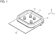
- FIG. 1 shows a connector 11 according to Embodiment 1.
- the connector 11 is used as, for instance, a garment-side connector for fitting a wearable device and has a housing 12 made of an insulating material.
- Four plug contacts 13 are retained in the housing 12, and, in addition, a sheet type conductive member 15 is retained by the housing 12.
- the sheet type conductive member 15 constitutes a sheet type connection object to which the connector 11 is connected.
- the four plug contacts 13 are arranged in two rows parallel to each other and disposed to project perpendicularly to the sheet type conductive member 15.
- the sheet type conductive member 15 is defined as extending in an XY plane, the arrangement direction of the four plug contacts 13 is referred to as "Y direction,” and the direction in which the four plug contacts 13 project is referred to as "+Z direction.”
- the Z direction is a fitting direction in which the connector 11 is fitted to a counter connector.
- FIG. 2 shows an exploded perspective view of the connector 11.
- the connector 11 includes a top insulator 16 and a bottom insulator 17, and these top and bottom insulators 16 and 17 constitute the housing 12.
- the four plug contacts 13 are disposed on the -Z direction side of the top insulator 16, and the sheet type conductive member 15 is disposed on the -Z direction side of the four plug contacts 13. Further, four inner contacts 18 are disposed on the -Z direction side of the sheet type conductive member 15, and the bottom insulator 17 is disposed on the -Z direction side of the four inner contacts 18. The four inner contacts 18 separately correspond to the four plug contacts 13.
- the top insulator 16 includes a recessed portion 16A opening in the +Z direction, and four contact through-holes 16B formed within the recessed portion 16A.
- the recessed portion 16A constitutes a counter connector accommodating portion in which part of a counter connector (not shown) is to be accommodated, and the four contact through-holes 16B separately correspond to the four plug contacts 13.
- a plurality of bosses 16C are formed to project in the -Z direction.
- the bottom insulator 17 includes a flat plate portion 17A, and four contact arrangement regions 17B are defined on a top surface, facing in the +Z direction, of the flat plate portion 17A.
- Each contact arrangement region 17B is a circular region at which the corresponding plug contact 13 is arranged via the sheet type conductive member 15.
- the four contact arrangement regions 17B are separately provided with four projections 17C projecting in the +Z direction from respectively center parts of the contact arrangement regions 17B.
- the flat plate portion 17A is provided with a plurality of through-holes 17D separately corresponding to the plurality of bosses 16C of the top insulator 16.
- each projection 17C formed in the contact arrangement region 17B of the bottom insulator 17 has a substantially columnar shape extending in the Z direction along a fitting axis C of the plug contact 13 disposed correspondingly to the contact arrangement region 17B, and an inner contact accommodating groove 17E is formed in the projection 17C and in the contact arrangement region 17B on the -X direction side of the projection 17C.
- the inner contact accommodating groove 17E is provided to accommodate the corresponding inner contact 18, passes the fitting axis C and extends along an XZ plane.
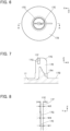
- the inner contact accommodating groove 17E penetrates a +Z directional portion of the projection 17C in the X direction and extends from a root part of the projection 17C to the contact arrangement region 17B as shown in FIG. 7 .
- the inner contact accommodating groove 17E includes: a first accommodating groove 17F formed at a +Z directional end portion, which serves as an opening end portion, of the inner contact accommodating groove 17E; and a second accommodating groove 17G disposed at an inner part on the -Z direction side of the first accommodating groove 17F and communicating with the first accommodating groove 17F.
- These first and second accommodating grooves 17F and 17G have different groove widths. That is, as shown in FIG.
- the first accommodating groove 17F has a first groove width W2 wider than the groove width W1
- the second accommodating groove 17G has a second groove width W3 wider than the groove width W1 and narrower than the first groove width W2.
- the projection 17C has a restriction portion 17H disposed inside the inner contact accommodating groove 17E and formed from a surface facing in the +X direction.
- the four plug contacts 13 are each made of a conductive material such as metal, and are to be connected to corresponding contacts of a counter connector (not shown) when part of the counter connector is accommodated in the recessed portion 16A of the top insulator 16.
- the plug contact 13 has a tubular portion 13A of cylindrical shape extending in the Z direction along the fitting axis C, and a flange 13B of flat plate shape extending from a -Z directional end portion of the tubular portion 13A along an XY plane.
- the tubular portion 13A includes a large diameter portion 13C situated on the -Z direction side and a small diameter portion 13D concentrically connected to the large diameter portion 13C on the +Z direction side of the large diameter portion 13C.
- the tubular portion 13A is provided in its interior with a recessed portion 13E opening in the -Z direction, and a receiving portion 13F is formed of a dent annularly extending along an XY plane in an inner surface of the recessed portion 13E at a +Z directional end portion of the small diameter portion 13D.
- a step portion 13G annularly extending along an XY plane is formed in the inner surface of the recessed portion 13E at a boundary portion between the large diameter portion 13C and the small diameter portion 13D.
- a distance L11 in the X direction from the receiving portion 13F to a part of an inner surface of the small diameter portion 13D which part faces the receiving portion 13F has a value smaller than an inside diameter L12 of the large diameter portion 13C and larger than an inside diameter L13 of the small diameter portion 13D.
- the fitting axis C is an axis passing the center of the tubular portion 13A and extending in the Z direction that is the fitting direction between the connector 11 and a counter connector.
- tubular portion 13A has a cylindrical shape
- the cross-sectional shape thereof is not limited to a circular shape
- the tubular portion 13A may have various cross-sectional shapes such as an elliptical shape and a polygonal shape as long as the tubular portion 13A is provided in its interior with the recessed portion 13E.
- Any of the four plug contacts 13 may be each used as a terminal for transmitting an electric signal.
- the sheet type conductive member 15 has a multilayer structure in which a plurality of wiring layers each formed from a conductor and a plurality of insulating layers are laminated.
- the sheet type conductive member 15 is provided with four circular opening portions 15A penetrating the sheet type conductive member 15 in the Z direction.
- the four opening portions 15A separately correspond to the four plug contacts 13.
- a wiring layer 15B is exposed toward the +Z direction at parts separately adjacent to the opening portions 15A on the -X direction side of the opening portions 15A, while an insulating layer 15C is exposed in a region excluding the four opening portions 15A and the four parts of the wiring layer 15B adjacent to these opening portions 15A.
- the opening portions 15A penetrate the sheet type conductive member 15 in the Z direction, as shown in FIG. 12 , the four opening portions 15A can be seen also on a bottom surface, facing in the -Z direction, of the sheet type conductive member 15.
- a wiring layer 15D is exposed toward the -Z direction at parts separately adjacent to the four opening portions 15A on the -X direction side of the opening portions 15A, while an insulating layer 15E is exposed in a region excluding the four opening portions 15A and the four parts of the wiring layer 15D adjacent to these opening portions 15A.
- a plurality of through-holes 15F separately corresponding to the plurality of bosses 16C of the top insulator 16 are formed at a peripheral portion of the sheet type conductive member 15.
- the inner contact 18 is formed of a metal sheet of flat plate shape that is cut in a predetermined shape and has conductivity, and has a flat plate portion 18A extending along an XZ plane.
- a first extending portion 18B extends in the -Z direction from a -X directional end portion of the flat plate portion 18A
- an arm portion 18C extends in the -X direction from a -Z directional end portion of the first extending portion 18B
- a second extending portion 18D extends in the -Z direction from a +X directional end portion of the flat plate portion 18A.
- the flat plate portion 18A, the first extending portion 18B, and the second extending portion 18D are inserted into the recessed portion 13E of the corresponding plug contact 13 when the connector 11 is assembled.
- a hook portion 18E is formed at the -X directional and +Z directional end portion of the flat plate portion 18A to project in the -X direction.
- the hook portion 18E projects in a right angle shape or a chevron shape toward the -X direction, and a first contacting portion P1 facing in the -Z direction is set at a -X directional end portion of the hook portion 18E.
- a protruding portion 18F protruding in a convex shape in the +X direction is formed at the +X directional end portion of the flat plate portion 18A on the -Z direction side from the first contacting portion P1, and a second contacting portion P2 facing in the +X direction is set on a +X directional end portion of the protruding portion 18F.
- a distance L21 in the X direction between the first contacting portion P1 and the second contacting portion P2 is slightly larger than the distance L11 in the X direction from the receiving portion 13D to a part of the inner surface of the small diameter portion 13D which part faces the receiving portion 13D, is smaller than the inside diameter L12 of the large diameter portion 13C, and is larger than the inside diameter L13 of the small diameter portion 13D in the plug contact 13 shown in FIG. 10 .
- a protruding portion 18G protruding in a convex shape toward the +Z direction is formed at a -X directional end portion of the arm portion 18C, and a third contacting portion P3 facing in the +Z direction is set on a +Z directional end portion of the protruding portion 18G.
- a restricted portion P4 facing in the -X direction is set on a lateral surface of a - Z directional end portion of the second extending portion 18D facing the first extending portion 18B.
- a press-fitting portion 18H of convex shape is formed on a surface, facing in the +Y direction, of the flat plate portion 18A to protrude in the +Y direction.
- the press-fitting portion 18H is formed by, for example, exerting a pressing force on the flat plate portion 18A from the -Y direction and deforming the flat plate portion 18A.
- a thickness D2 of the inner contact 18 at a part where the press-fitting portion 18H is formed is larger than a thickness D1 of the inner contact 18 at a part where the press-fitting portion 18H is not formed.
- the press-fitting portion 18H is formed at an X directional position corresponding to the first accommodating groove 17F and the second accommodating groove 17G of the projection 17C of the bottom insulator 17 shown in FIG. 7 .
- the groove width W1 of the inner contact accommodating groove 17E of the projection 17C of the bottom insulator 17 shown in FIG. 8 is slightly larger than the thickness D1 of the inner contact 18 at the part where the press-fitting portion 18H is not formed
- the first groove width W2 of the first accommodating groove 17F is substantially equal to the thickness D2 of the inner contact 18 at the part where the press-fitting portion 18H is formed
- the second groove width W3 of the second accommodating groove 17G is smaller than the thickness D2 of the inner contact 18 at the part where the press-fitting portion 18H is formed.
- the four contact through-holes 16B of the top insulator 16, the four plug contacts 13, the four opening portions 15A of the sheet type conductive member 15, the four inner contacts 18, and the four contact arrangement regions 17B of the bottom insulator 17 are arranged so as to align with each other in the Z direction.
- bosses 16C of the top insulator 16, the through-holes 15F of the sheet type conductive member 15, and the through-holes 17D of the bottom insulator 17 are arranged so as to align with each other in the Z direction.
- the four inner contacts 18 are separately retained in the inner contact accommodating grooves 17E of the four projections 17C of the bottom insulator 17. Since the first accommodating groove 17F formed at the +Z directional end portion of the inner contact accommodating groove 17E of the projection 17C has the first groove width W2 substantially equal to the thickness D2 of the inner contact 18 at the part where the press-fitting portion 18H is formed, as shown in FIG. 16 , each inner contact 18 is retained in a state where the press-fitting portion 18H is inserted into the first accommodating groove 17F of the corresponding projection 17C from the +Z direction and is situated at the boundary portion between the first accommodating groove 17F and the second accommodating groove 17G.
- each plug contact 13 is inserted into the corresponding one of the four contact through-holes 16B of the top insulator 16 from the -Z direction, and the bottom insulator 17 is pressed toward the top insulator 16 in the +Z direction with the sheet type conductive member 15 being sandwiched therebetween.
- the inner contact 18 retained by the inner contact accommodating groove 17E of the projection 17C of the bottom insulator 17 is pushed up in the +Z direction along with the bottom insulator 17, and the flat plate portion 18A of the inner contact 18 is inserted into the recessed portion 13E of the corresponding plug contact 13 through the opening portion 15A of the sheet type conductive member 15.
- the distance L21 in the X direction between the -X directional end portion of the hook portion 18E and the +X directional end portion of the protruding portion 18F of the inner contact 18 shown in FIG. 14 is smaller than the inside diameter L12 of the large diameter portion 13C and larger than the inside diameter L13 of the small diameter portion 13D of the plug contact 13. Therefore, while the flat plate portion 18A of the inner contact 18 can move in the +Z direction within the large diameter portion 13C of the plug contact 13, the protruding portion 18F situated on the - Z direction side from the hook portion 18E cannot enter the small diameter portion 13D and is hooked by the step portion 13G situated at the boundary portion between the large diameter portion 13C and the small diameter portion 13D as shown in FIG. 18 .
- the inner contact 18 takes a position rotated counterclockwise by a predetermined angle in FIG. 18 and moves in the +Z direction within the recessed portion 13E of the plug contact 13.
- the first extending portion 18B and the second extending portion 18D of the inner contact 18 are also inserted into the recessed portion 13E of the plug contact 13, and further, the protruding portion 18G formed at the -X directional end portion of the arm portion 18C extending in the -X direction from the -Z directional end portion of the first extending portion 18B makes contact with the bottom surface on the -Z direction side of the sheet type conductive member 15.
- the inner contact 18 is rotated clockwise in FIG. 19 and retained by the plug contact 13 in a state where the protruding portion 18G of the arm portion 18C is pressed in the -Z direction from the sheet type conductive member 15, and the protruding portion 18F of the flat plate portion 18A is pressed in the -X direction from the inner surface of the small diameter portion 13D of the plug contact 13.
- the second groove width W3 of the second accommodating groove 17G of the projection 17C shown in FIG. 8 has the second groove width W3 narrower than the thickness D2 of the inner contact 18 at the part where the press-fitting portion 18H is formed, the press-fitting portion 18H is press-fitted in the second accommodating groove 17G of the projection 17C, and the inner contact 18 is thus retained by the projection 17C of the bottom insulator 17.
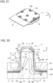
- the bosses 16C of the top insulator 16 sequentially penetrate the through-holes 15F of the sheet type conductive member 15, and the through-holes 17D of the bottom insulator 17. Thereafter, as shown in FIG. 21 , the top insulator 16 and the bottom insulator 17 are fixed to each other through heat deformation of a tip of each of the plurality of bosses 16C projecting on the -Z direction side of the bottom insulator 17. Thus, the assembling operation of the connector 11 is completed.
- the restricted portion P4 set at the -Z directional end portion of the second extending portion 18D of the inner contact 18 makes contact with the restriction portion 17H formed inside the inner contact accommodating groove 17E of the projection 17C of the bottom insulator 17, whereby counterclockwise rotation of the inner contact 18 in FIG. 22 is restricted.
- the flange 13B of the plug contact 13 is situated around the corresponding opening portion 15A of the sheet type conductive member 15, and the sheet type conductive member 15 is sandwiched between the protruding portion 18G formed at the -X directional end portion of the arm portion 18C of the inner contact 18 and a bottom surface on the -Z direction side of the flange 13B of the plug contact 13.
- the inner contact 18 is retained in a state where the first contacting portion P1 set at the hook portion 18E of the flat plate portion 18A is receiving a force F1 acting in the +X direction and the +Z direction from the receiving portion 13F of the plug contact 13, the second contacting portion P2 set at the protruding portion 18F of the flat plate portion 18A is receiving a force F2 acting in the -X direction from the inner surface of the small diameter portion 13D of the plug contact 13, the third contacting portion P3 set at the protruding portion 18G of the arm portion 18C is receiving a force F3 acting in the -Z direction from the bottom surface of the sheet type conductive member 15, and the restricted portion P4 set at the second extending portion 18D is receiving a force F4 acting in the +X direction from the restriction portion 17H of the bottom insulator 17.
- first and second contacting portions P1 and P2 are pressed against and make contact with the inner surface of the recessed portion 13E of the plug contact 13, whereby the inner contact 18 is electrically connected to the plug contact 13.
- the top surface on the +Z direction side of the sheet type conductive member 15 is pressed against the bottom surface of the flange 13B of the plug contact 13, while the bottom surface on the -Z direction side of the sheet type conductive member 15 is pressed against the third contacting portion P3 of the inner contact 18.
- the wiring layer 15B is exposed at parts separately adjacent to the opening portions 15A on the -X direction side of the opening portions 15A, and on the bottom surface of the sheet type conductive member 15, the wiring layer 15D is exposed at separately adjacent to the opening portions 15A on the -X direction side of the opening portions 15A.
- the wiring layer 15B on the top surface of the sheet type conductive member 15 makes contact with the bottom surface of the flange 13B of the plug contact 13 with predetermined contact pressure, while the wiring layer 15D on the bottom surface of the sheet type conductive member 15 makes contact with the third contacting portion P3 of the inner contact 18 with predetermined contact pressure.
- the wiring layer 15B exposed on the top surface of the sheet type conductive member 15 is electrically connected to the plug contact 13 directly, and the wiring layer 15D exposed on the bottom surface of the sheet type conductive member 15 is electrically connected to the plug contact 13 via the inner contact 18. In other words, both the wiring layers 15B and 15D are connected to the plug contact 13.
- both the wiring layer 15B and the wiring layer 15D formed of the conductors disposed on the top surface side and the bottom surface side of the sheet type conductive member 15 can be electrically connected to a single plug contact 13 by use of the inner contact 18.
- the plug contact 13 can be electrically connected to the conductor on the top surface side of the sheet type conductive member.
- the plug contact 13 can be electrically connected to the conductor on the bottom surface side of the sheet type conductive member.
- the plug contact 13 can be electrically connected to both the conductors on the top surface side and the bottom surface side of the sheet type conductive member.
- a connection object is a sheet type conductive member having a multilayer structure in which conductors constituting shield layers are separately exposed on the top surface side and the bottom surface side and a conductor constituting a signal wiring layer is disposed between these shield layers so as to be insulated from both the shield layers, a shield effect is exhibited to the signal wiring layer when the plug contact 13 connected to the shield layers on the top surface side and the bottom surface side is connected to a ground potential, and it is possible to carry out highly accurate signal transmission with reduced influence of external disturbances caused by, for example, electromagnetic waves.
- each of the plug contacts 13 is sandwiched between the top insulator 16 and the bottom insulator 17, and the plug contacts 13 are thereby fixed to the top insulator 16 and the bottom insulator 17.
- the distance LX in the X direction between the first contacting portion P1 and the third contacting portion P3 can be decreased. If the restricted portion P4 of the inner contact 18 does not contact the restriction portion 17H of the projection 17C of the bottom insulator 17 and does not receive the force F4 acting in the +X direction from the restriction portion 17H, in order to retain the inner contact 18 with the balanced moments, it is necessary to increase the distance LX in the X direction between the first contacting portion P1 and the third contacting portion P3 to increase the clockwise moments in FIG. 22 . That is, the length of the arm portion 18C extending in the X direction would need to be made larger, resulting in enlargement of the connector 11.
- the plug contact 13 can be electrically connected to the wiring layer 15B or 15D of the sheet type conductive member 15, and the small-sized connector 11 can be achieved.
- FIG. 23 shows an exploded perspective view of a connector 21 according to Embodiment 2.
- the connector 21 includes a housing 22 constituted of the top insulator 16 and a bottom insulator 27.
- the four plug contacts 13 are disposed on the -Z direction side of the top insulator 16, and a sheet type conductive member 25 is disposed on the -Z direction side of the four plug contacts 13. Further, four inner contacts 28 are disposed on the -Z direction side of the sheet type conductive member 25, four boss members 29 are disposed on the -Z direction side of the four inner contacts 28, and the bottom insulator 27 is disposed on the -Z direction side of the four boss members 29.
- the top insulator 16 and the four plug contacts 13 are the same as those used in the connector 11 of Embodiment 1.
- the bottom insulator 27 includes a flat plate portion 27A, and four contact arrangement regions 27B are defined on a top surface, facing in the +Z direction, of the flat plate portion 27A.
- Each contact arrangement region 27B is a circular region at which the corresponding plug contact 13 is arranged via the sheet type conductive member 25.
- the four contact arrangement regions 27B are separately provided with four protrusion portions 27C projecting in the +Z direction from respective center parts of the contact arrangement regions 27B.
- the flat plate portion 27A is provided with a plurality of through-holes 27D separately corresponding to the plurality of bosses 16C of the top insulator 16.
- the contact arrangement region 27B of the bottom insulator 27 has a recessed and circular shape
- the protrusion portion 27C has a columnar shape extending in the Z direction along the fitting axis C of the plug contact 13 disposed correspondingly to the contact arrangement region 27B.
- a lateral surface along an outer periphery of the protrusion portion 27C forms a restriction portion 27E.
- the boss member 29 includes a base portion 29A of circular disk shape and a projection 29B projecting in the +Z direction from a center part of the base portion 29A, and an inner contact accommodating groove 29C is formed in the projection 29B and the base portion 29A on the -X direction side of the projection 29B.
- the base portion 29A has such a size as to be accommodated in the contact arrangement region 27B of recess shape of the bottom insulator 27.
- the inner contact accommodating groove 29C is configured to accommodate the corresponding inner contact 28, passes the fitting axis C and extends along an XZ plane.
- the inner contact accommodating groove 29C penetrates a +Z directional portion of the projection 29B in the X direction and extends from a root part of the projection 29B to the base portion 29A as shown in FIG. 29 .
- the inner contact accommodating groove 29C has a Y directional groove width slightly larger than the thickness of the inner contact 28.
- the projection 29B includes an abutment portion 29D disposed inside the inner contact accommodating groove 29C and facing in the +Z direction.
- the boss member 29 includes a protrusion portion accommodating hole 29E extending from a bottom surface on the -Z direction side of the base portion 29A along the fitting axis C to the inside of the projection 29B and communicating with the inner contact accommodating groove 29C.
- the protrusion portion accommodating hole 29E opens in the -Z direction from the bottom surface on the -Z direction side of the base portion 29A and is configured to accommodate the protrusion portion 27C of the bottom insulator 27 when the connector 21 is assembled.
- the sheet type conductive member 25 has a multilayer structure in which a plurality of wiring layers each formed from a conductor and a plurality of insulating layers are laminated.
- the sheet type conductive member 25 is provided with four circular opening portions 25A penetrating the sheet type conductive member 25 in the Z direction.
- the four opening portions 25A separately correspond to the four plug contacts 13.
- a wiring layer 25B is exposed toward the +Z direction and around each of the opening portions 25A so as to surround the opening portions 25A, while an insulating layer 25C is exposed in a region excluding the four opening portions 25A and the four parts of the wiring layer 25B disposed around these opening portions 25A.
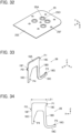
- the opening portions 25A penetrate the sheet type conductive member 25 in the Z direction, as shown in FIG. 32 , the four opening portions 25A can be seen also on a bottom surface, facing in the -Z direction, of the sheet type conductive member 25.
- a wiring layer 25D is exposed toward the -Z direction and around the four opening portions 25A so as to surround the opening portions 25A, while an insulating layer 25E is exposed in a region excluding the four opening portions 25A and the four parts of the wiring layer 25D disposed around these opening portions 25A.
- a plurality of through-holes 25F separately corresponding to the plurality of bosses 16C of the top insulator 16 are formed at a peripheral portion of the sheet type conductive member 25.
- FIGS. 33 and 34 show the inner contact 28.
- the inner contact 28 does not have the press-fitting portion 18H formed on the surface of the flat plate portion 18A in the inner contact 18 used in Embodiment 1, and the configuration of the inner contact 28 is the same as that of the inner contact 18 expect the press-fitting portion 18H.
- the inner contact 28 is formed from a metal sheet of flat plate shape that is cut in a predetermined shape and has conductivity, and includes the flat plate portion 18A extending along an XZ plane, the first extending portion 18B extending in the -Z direction from the -X directional end portion of the flat plate portion 18A, the arm portion 18C extending in the -X direction from the -Z directional end portion of the first extending portion 18B, and the second extending portion 18D extending in the -Z direction from the +X directional end portion of the flat plate portion 18A.
- the hook portion 18E projecting in the -X direction is formed at the -X directional and +Z directional end portion of the flat plate portion 18A, and the first contacting portion P1 facing in the -Z direction is set at the -X directional end portion of the hook portion 18E.
- the protruding portion 18F protruding in the +X direction is formed at a +X directional end portion of the flat plate portion 18A on the -Z direction side from the first contacting portion P1, and the second contacting portion P2 facing in the +X direction is set at the +X directional end portion of the protruding portion 18F.
- the distance L21 in the X direction between the first contacting portion P1 and the second contacting portion P2 is slightly larger than the distance L11 in the X direction from the receiving portion 13D to a part of the inner surface of the small diameter portion 13D which part faces the receiving portion 13D, is smaller than the inside diameter L12 of the large diameter portion 13C, and is larger than the inside diameter L13 of the small diameter portion 13D in the plug contact 13 shown in FIG. 10 .
- the protruding portion 18G protruding in the +Z direction is formed at the -X directional end portion of the arm portion 18C, and the third contacting portion P3 facing in the +Z direction is set at a +Z directional end portion of the protruding portion 18G.
- the restricted portion P4 facing in the -X direction is set on a part of the lateral surface of a -Z directional end portion of the second extending portion 18D which part faces the first extending portion 18B.
- the four contact through-holes 16B of the top insulator 16, the four plug contacts 13, the four opening portions 25A of the sheet type conductive member 25, the four inner contacts 28, the four boss members 29, and the four contact arrangement regions 27B of the bottom insulator 27 are arranged so as to align with each other in the Z direction.
- bosses 16C of the top insulator 16, the through-holes 25F of the sheet type conductive member 25, and the through-holes 27D of the bottom insulator 27 are arranged so as to align with each other in the Z direction.
- the inner contact accommodating groove 29C has a Y directional groove width slightly larger than the thickness of the inner contact 28, the inner contact 28 is inserted into the inner contact accommodating groove 29C from the +Z direction, and as shown in FIG. 35 , the inner contact 28 is retained in a state where a -Z directional end portion of the flat plate portion 18A between the first extending portion 18B and the second extending portion 18D is making contact with the abutment portion 29D within the inner contact accommodating groove 29C.
- each plug contact 13 is inserted into the corresponding one of the four contact through-holes 16B of the top insulator 16 from the -Z direction, and each of the four boss members 29 is pressed toward the top insulator 16 in the +Z direction with the sheet type conductive member 25 being sandwiched therebetween.
- the inner contact 28 retained by the inner contact accommodating groove 29C of the projection 29B of the boss member 29 is, together with the boss member 29, pushed up in the +Z direction, and the flat plate portion 18A of the inner contact 28 is inserted into the recessed portion 13E of the corresponding plug contact 13 through the opening portion 25A of the sheet type conductive member 25.
- the distance L21 in the X direction between the -X directional end portion of the hook portion 18E and the +X directional end portion of the protruding portion 18F of the inner contact 28 shown in FIG. 34 is smaller than the inside diameter L12 of the large diameter portion 13C and larger than the inside diameter L13 of the small diameter portion 13D of the plug contact 13. Therefore, while the flat plate portion 18A of the inner contact 28 can move in the +Z direction within the large diameter portion 13C of the plug contact 13, the protruding portion 18F situated on the - Z direction side from the hook portion 18E cannot enter the small diameter portion 13D and is hooked by the step portion 13G situated at the boundary portion between the large diameter portion 13C and the small diameter portion 13D as shown in FIG. 36 .
- the inner contact 28 takes a position rotated counterclockwise by a predetermined angle in FIG. 36 and moves in the +Z direction within the recessed portion 13E of the plug contact 13.
- the first extending portion 18B and the second extending portion 18D of the inner contact 28 are also inserted into the recessed portion 13E of the plug contact 13, and further, the protruding portion 18G formed at the -X directional end portion of the arm portion 18C extending in the -X direction from the -Z directional end of the first extending portion 18B makes contact with the bottom surface on the -Z direction side of the sheet type conductive member 25.
- the inner contact 28 is rotated clockwise in FIG. 37 and retained by the plug contact 13 in a state where the protruding portion 18G of the arm portion 18C is pressed in the -Z direction from the sheet type conductive member 25 and elastically deformed, and the protruding portion 18F of the flat plate portion 18A is pressed in the -X direction from the inner surface of the small diameter portion 13D of the plug contact 13.
- each of the four protrusion portions 27C of the bottom insulator 27 is inserted into the protrusion portion accommodating hole 29E of the corresponding boss member 29 from the -Z direction.
- the bosses 16C of the top insulator 16 sequentially penetrate the through-holes 25F of the sheet type conductive member 25, and the through-holes 27D of the bottom insulator 27. Thereafter, the top insulator 16 and the bottom insulator 27 are fixed to each other through heat deformation of a tip of each of the plurality of bosses 16C projecting on the -Z direction side of the bottom insulator 27. Thus, the assembling operation of the connector 21 is completed.
- the base portion 29A of the boss member 29 is accommodated in the contact arrangement region 27B of recess shape of the bottom insulator 27, the restriction portion 27E constituted of the lateral surface of the protrusion portion 27C of the bottom insulator 27 inserted in the protrusion portion accommodating hole 29E of the boss member 29 makes contact with the restricted portion P4 set at the -Z directional end portion of the second extending portion 18D of the inner contact 28 inserted in the inner contact accommodating groove 29C communicating with the protrusion portion accommodating hole 29E. Therefore, counterclockwise rotation of the inner contact 28 in FIG. 38 is restricted.
- the flange 13B of the plug contact 13 is situated around the corresponding opening portion 25A of the sheet type conductive member 25, and the sheet type conductive member 25 is sandwiched between the protruding portion 18G formed at the -X directional end portion of the arm portion 18C of the inner contact 28 and the bottom surface on the -Z direction side of the flange 13B of the plug contact 13.
- the inner contact 28 is retained in a state where the first contacting portion P1 set at the hook portion 18E of the flat plate portion 18A is receiving the force F1 acting in the +X direction and the +Z direction from the receiving portion 13F of the plug contact 13, the second contacting portion P2 set at the protruding portion 18F of the flat plate portion 18A is receiving the force F2 acting in the -X direction from the inner surface of the small diameter portion 13D of the plug contact 13, the third contacting portion P3 set at the protruding portion 18G of the arm portion 18C is receiving the force F3 acting in the -Z direction from the bottom surface of the sheet type conductive member 25 and is elastically displaced, and the restricted portion P4 set at the second extending portion 18D is receiving the force F4 acting in the +X direction from the restriction portion 27E of the protrusion portion 27C of the bottom insulator 27.
- first and second contacting portions P1 and P2 are pressed against and make contact with the inner surface of the recessed portion 13E of the plug contact 13, whereby the inner contact 28 is electrically connected to the plug contact 13.
- the top surface on the +Z direction side of the sheet type conductive member 25 is pressed against the bottom surface of the flange 13B of the plug contact 13, while the bottom surface on the -Z direction side of the sheet type conductive member 25 is pressed against the third contacting portion P3 of the inner contact 28.
- the wiring layer 25B is exposed around the opening portions 25A
- the wiring layer 25D is exposed around the opening portions 25A.
- the wiring layer 25B on the top surface of the sheet type conductive member 25 makes contact with the bottom surface of the flange 13B of the plug contact 13 with predetermined contact pressure, while the wiring layer 25D on the bottom surface of the sheet type conductive member 25 makes contact with the third contacting portion P3 of the inner contact 28 with predetermined contact pressure.
- the wiring layer 25B exposed on the top surface of the sheet type conductive member 25 is electrically connected to the plug contact 13 directly, and the wiring layer 25D exposed on the bottom surface of the sheet type conductive member 25 is electrically connected to the plug contact 13 via the inner contact 28. In other words, both the wiring layers 25B and 25D are connected to the plug contact 13.
- both the wiring layer 25B and the wiring layer 25D respectively formed of the conductor disposed on the top surface side and the conductor disposed on the bottom surface side of the sheet type conductive member 25 can be electrically connected to the single plug contact 13.
- the plug contact 13 can be electrically connected to the conductor on the top surface side of the sheet type conductive member.
- the plug contact 13 can be electrically connected to the conductor on the bottom surface side of the sheet type conductive member.
- the force F4 is applied from the restriction portion 27E of the protrusion portion 27C of the bottom insulator 27 to the restricted portion P4 of the inner contact 28, whereby the small-sized connector 21 can be achieved.
- the tubular portion 13A of the plug contact 13 has a cylindrical shape extending along the fitting axis C
- the projection 29B of the boss member 29 is formed to project on the center part of the base portion 29A of circular disk shape
- the protrusion portion 27C of the bottom insulator 27 is formed to project on the center part of the contact arrangement region 27B of circular shape
- the wiring layers 25B, 25D of the sheet type conductive member 25 are respectively exposed on the top surface and the bottom surface of the sheet type conductive member 25 so as to surround the opening portions 25A.
- the boss member 29 in which the inner contact 28 is retained by the projection 29B is pressed in the +Z direction toward the top insulator 16, even with the inner contact 28 facing in either of the rotational directions about the fitting axis C, the flat plate portion 18A, the first extending portion 18B, and the second extending portion 18D of the inner contact 28 are inserted into the recessed portion 13E of the plug contact 13, and further, the protrusion portion 27C of the bottom insulator 27 is inserted into the protrusion portion accommodating hole 29E of the boss member 29, so that the wiring layers 25B, 25D of the sheet type conducive member 25 can be electrically connected to the plug contact 13.
- a part facing the restricted portion P4 of the inner contact 28 serves as the restriction portion 27E and applies the force F4 to the restricted portion P4.
- the plug contact 13 is connected to both the wiring layer 15B, 25B and the wiring layer 15D, 25D respectively exposed on the top surface side and the bottom surface side of the sheet type conductive member 15, 25 in Embodiments 1 and 2 above, only the wiring layer 15D, 25D exposed on the bottom surface side of the sheet type conductive member 15 may be connected to the plug contact 13, for instance.
- the sheet type conductive member 15, 25 used in Embodiments 1 and 2 above has a multilayer structure, the invention is not limited thereto, and it suffices if the sheet type conductive member has a conductor exposed on at least one surface thereof.
- the two layers of the conductors i.e., the wiring layer 15B, 25B and the wiring layer 15D, 25D of the sheet type conductive member 15, 25 are connected to the single plug contact 13 in Embodiments 1 and 2 above, the invention is not limited thereto, and three or more layers of conductors may be connected to the single plug contact 13.
- the connector 11, 21 according to Embodiments 1 and 2 above has the four plug contacts 13, the invention is not limited to this number of the plug contacts 13, and it suffices if the connector includes at least a single plug contact 13 to be electrically connected to a conductor exposed on at least one surface of the sheet type conductive member 15, 25.
Landscapes
- Engineering & Computer Science (AREA)
- Microelectronics & Electronic Packaging (AREA)
- Coupling Device And Connection With Printed Circuit (AREA)
Abstract
Description
- The present invention relates to a connector, particularly to a connector that is connected to a sheet type connection object having a conductor exposed on at least one surface of the connection object.
- In recent years, attention has been drawn to so-called smart clothes that can obtain user's biological data such as the heart rate and the body temperature only by being worn by the user. Such smart clothes have an electrode disposed at a measurement site, and when a wearable device serving as a measurement device is electrically connected to the electrode, biological data can be transmitted to the wearable device.
- The electrode and the wearable device can be interconnected by, for instance, use of a connector connected to a conductor drawn from the electrode.
- As a connector of this type, for example,
JP 2018-129244 A FIG. 39 . This connector includes ahousing 2 and abase member 3 that are separately disposed on opposite sides of aflexible substrate 1 to sandwich theflexible substrate 1.Tubular portions 4A ofcontacts 4 are passed through contact through-holes 2A of thehousing 2, andflanges 4B of thecontacts 4 are sandwiched between thehousing 2 andconductors 1A exposed on the top surface of theflexible substrate 1. - In this state, by pushing the
base member 3 toward thehousing 2, as shown inFIG. 40 , aprojection 3A of thebase member 3 is inserted into aprojection accommodating portion 4C of thecontact 4 with theflexible substrate 1 being sandwiched therebetween, and an inner surface of theprojection accommodating portion 4C makes contact with theconductor 1A with a predetermined contact force, whereby thecontact 4 is electrically connected to theconductor 1A. - Further,
housing fixing posts 3B formed to project from thebase member 3 are press-fitted into post accommodatingportions 2B of thehousing 2 as shown inFIG. 39 , so that thehousing 2 and thebase member 3 are fixed to each other. - When a wearable device is fitted with the connector disclosed in
JP 2018-129244 A - However, when the
conductor 1A is exposed on the bottom surface of theflexible substrate 1, the connector ofJP 2018-129244A conductor 1A to thecontact 4, disadvantageously. - The present invention has been made to solve the foregoing problem and aims at providing a connector that enables an electrical connection of a contact to a conductor of a connection object regardless of whether the conductor is exposed on the top surface or the bottom surface of the connection object.
- A connector according to the present invention comprises:
- a plug contact having conductivity and including a tubular portion and a flange, the tubular portion extending along a fitting axis and being provided in its interior with a recessed portion, and the flange extending from a base end of the tubular portion in a direction orthogonal to the fitting axis;
- an inner contact having conductivity and being supported while having part of the inner contact inserted in the recessed portion; and
- a housing retaining the plug contact,
- wherein the housing includes a restriction portion that is disposed in the recessed portion of the plug contact and is configured to restrict rotation of the inner contact,
- the inner contact includes
- a first contacting portion that makes contact with an inner surface of the recessed portion to be electrically connected to the plug contact,
- a second contacting portion that makes contact with the inner surface of the recessed portion on an opposite side from the first contacting portion across the fitting axis and at a position closer to the base end of the recessed portion than the first contacting portion is,
- a third contacting portion extending in a direction orthogonal to the fitting axis and facing the flange, and
- a restricted portion that faces in an opposite direction from the second contacting portion and makes contact with the restriction portion at a position closer to the base end of the recessed portion than the second contacting portion is, and
- part of a connection object of sheet shape having a conductor exposed on at least one surface of the connection object is sandwiched between a bottom surface of the flange of the plug contact and the third contacting portion of the inner contact in a direction along the fitting axis, the bottom surface of the flange makes contact with a top surface of the connection object, and the third contacting portion makes contact with a bottom surface of the connection object, whereby the plug contact is electrically connected to the conductor directly when the conductor is exposed on the top surface of the connection object, and the plug contact is electrically connected to the conductor via the inner contact when the conductor is exposed on the bottom surface of the connection object.
-
-
FIG. 1 is a perspective view showing a connector according toEmbodiment 1 connected to a connection object. -
FIG. 2 is an exploded perspective view of the connector according toEmbodiment 1. -
FIG. 3 is a perspective view showing a top insulator used in the connector ofEmbodiment 1. -
FIG. 4 is a perspective view showing a bottom insulator used in the connector ofEmbodiment 1. -
FIG. 5 is a perspective view showing a projection formed in the bottom insulator inEmbodiment 1. -
FIG. 6 is a plan view showing the projection formed in the bottom insulator inEmbodiment 1. -
FIG. 7 is a cross-sectional view taken along line A-A inFIG. 6 . -
FIG. 8 is a partial cross-sectional view showing an inner contact accommodating groove of the projection formed in the bottom insulator inEmbodiment 1. -
FIG. 9 is a perspective view showing a plug contact used in the connector ofEmbodiment 1. -
FIG. 10 is a cross-sectional view showing the plug contact used in the connector ofEmbodiment 1. -
FIG. 11 is a perspective view of a connection object to be connected to the connector ofEmbodiment 1, as viewed from an obliquely upper position. -
FIG. 12 is a perspective view of the connection object to be connected to the connector ofEmbodiment 1, as viewed from an obliquely lower position. -
FIG. 13 is a perspective view showing an inner contact used in the connector ofEmbodiment 1. -
FIG. 14 is a front view showing the inner contact used in the connector ofEmbodiment 1. -
FIG. 15 is a side view showing the inner contact used in the connector ofEmbodiment 1. -
FIG. 16 is a partially broken perspective view showing the inner contact to be inserted in the inner contact accommodating groove of the connector ofEmbodiment 1 at the start of assembling. -
FIG. 17 is a cross-sectional view showing the connector ofEmbodiment 1 at the start of assembling. -
FIG. 18 is a cross-sectional view showing the connector ofEmbodiment 1 in the process of assembling. -
FIG. 19 is another cross-sectional view showing the connector ofEmbodiment 1 in the process of assembling. -
FIG. 20 is a partially broken perspective view showing the inner contact accommodated in the inner contact accommodating groove of the connector ofEmbodiment 1 in the process of assembling. -
FIG. 21 is a perspective view of the connector ofEmbodiment 1 in the process of assembling, as viewed from an obliquely lower position. -
FIG. 22 is a cross-sectional view showing the connector ofEmbodiment 1 connected to the connection object. -
FIG. 23 is an exploded perspective view of a connector according toEmbodiment 2. -
FIG. 24 is a perspective view showing a bottom insulator used in the connector ofEmbodiment 2. -
FIG. 25 is an enlarged view of a main part ofFIG. 24 . -
FIG. 26 is a perspective view of a boss member used in the connector ofEmbodiment 2, as viewed from an obliquely upper position. -
FIG. 27 is a perspective view of the boss member used in the connector ofEmbodiment 2, as viewed from an obliquely lower position. -
FIG. 28 is a plan view showing the boss member used in the connector ofEmbodiment 2. -
FIG. 29 is a cross-sectional view taken along line B-B inFIG. 28 . -
FIG. 30 is a cross-sectional view taken along line C-C inFIG. 28 . -
FIG. 31 is a perspective view of a connection object to be connected to the connector ofEmbodiment 2, as viewed from an obliquely upper position. -
FIG. 32 is a perspective view of the connection object to be connected to the connector ofEmbodiment 2, as viewed from an obliquely lower position. -
FIG. 33 is a perspective view showing an inner contact used in the connector ofEmbodiment 2. -
FIG. 34 is a front view showing the inner contact used in the connector ofEmbodiment 2. -
FIG. 35 is a cross-sectional view showing the connector ofEmbodiment 2 at the start of assembling. -
FIG. 36 is a cross-sectional view showing the connector ofEmbodiment 2 in the process of assembling. -
FIG. 37 is another cross-sectional view showing the connector ofEmbodiment 2 in the process of assembling. -
FIG. 38 is a cross-sectional view showing the connector ofEmbodiment 2 connected to the connection object. -
FIG. 39 is an exploded perspective view of a conventional connector. -
FIG. 40 is a partial cross-sectional view showing the conventional connector. - Embodiments of the present invention are described below based on the accompanying drawings.
-
FIG. 1 shows aconnector 11 according toEmbodiment 1. Theconnector 11 is used as, for instance, a garment-side connector for fitting a wearable device and has ahousing 12 made of an insulating material. Fourplug contacts 13 are retained in thehousing 12, and, in addition, a sheet typeconductive member 15 is retained by thehousing 12. The sheet typeconductive member 15 constitutes a sheet type connection object to which theconnector 11 is connected. - The four
plug contacts 13 are arranged in two rows parallel to each other and disposed to project perpendicularly to the sheet typeconductive member 15. - For convenience, the sheet type
conductive member 15 is defined as extending in an XY plane, the arrangement direction of the fourplug contacts 13 is referred to as "Y direction," and the direction in which the fourplug contacts 13 project is referred to as "+Z direction." The Z direction is a fitting direction in which theconnector 11 is fitted to a counter connector. -
FIG. 2 shows an exploded perspective view of theconnector 11. Theconnector 11 includes atop insulator 16 and abottom insulator 17, and these top andbottom insulators housing 12. - The four
plug contacts 13 are disposed on the -Z direction side of thetop insulator 16, and the sheet typeconductive member 15 is disposed on the -Z direction side of the fourplug contacts 13. Further, fourinner contacts 18 are disposed on the -Z direction side of the sheet typeconductive member 15, and thebottom insulator 17 is disposed on the -Z direction side of the fourinner contacts 18. The fourinner contacts 18 separately correspond to the fourplug contacts 13. - As shown in
FIG. 3 , thetop insulator 16 includes a recessedportion 16A opening in the +Z direction, and four contact through-holes 16B formed within the recessedportion 16A. The recessedportion 16A constitutes a counter connector accommodating portion in which part of a counter connector (not shown) is to be accommodated, and the four contact through-holes 16B separately correspond to the fourplug contacts 13. In addition, on a surface, facing in the -Z direction, of thetop insulator 16, a plurality ofbosses 16C are formed to project in the -Z direction. - As shown in
FIG. 4 , thebottom insulator 17 includes aflat plate portion 17A, and fourcontact arrangement regions 17B are defined on a top surface, facing in the +Z direction, of theflat plate portion 17A. Eachcontact arrangement region 17B is a circular region at which thecorresponding plug contact 13 is arranged via the sheet typeconductive member 15. The fourcontact arrangement regions 17B are separately provided with fourprojections 17C projecting in the +Z direction from respectively center parts of thecontact arrangement regions 17B. - In addition, the
flat plate portion 17A is provided with a plurality of through-holes 17D separately corresponding to the plurality ofbosses 16C of thetop insulator 16. - As shown in
FIGS. 5 and6 , eachprojection 17C formed in thecontact arrangement region 17B of thebottom insulator 17 has a substantially columnar shape extending in the Z direction along a fitting axis C of theplug contact 13 disposed correspondingly to thecontact arrangement region 17B, and an innercontact accommodating groove 17E is formed in theprojection 17C and in thecontact arrangement region 17B on the -X direction side of theprojection 17C. - The inner
contact accommodating groove 17E is provided to accommodate the correspondinginner contact 18, passes the fitting axis C and extends along an XZ plane. The innercontact accommodating groove 17E penetrates a +Z directional portion of theprojection 17C in the X direction and extends from a root part of theprojection 17C to thecontact arrangement region 17B as shown inFIG. 7 . - In addition, the inner
contact accommodating groove 17E includes: a firstaccommodating groove 17F formed at a +Z directional end portion, which serves as an opening end portion, of the innercontact accommodating groove 17E; and a secondaccommodating groove 17G disposed at an inner part on the -Z direction side of the firstaccommodating groove 17F and communicating with the firstaccommodating groove 17F. These first and secondaccommodating grooves FIG. 8 , as compared to a Y directional groove width W1 of the other part of the innercontact accommodating groove 17E than the firstaccommodating groove 17F and the secondaccommodating groove 17G, the firstaccommodating groove 17F has a first groove width W2 wider than the groove width W1, while the secondaccommodating groove 17G has a second groove width W3 wider than the groove width W1 and narrower than the first groove width W2. - Further, as shown in
FIG. 7 , theprojection 17C has arestriction portion 17H disposed inside the innercontact accommodating groove 17E and formed from a surface facing in the +X direction. - The four
plug contacts 13 are each made of a conductive material such as metal, and are to be connected to corresponding contacts of a counter connector (not shown) when part of the counter connector is accommodated in the recessedportion 16A of thetop insulator 16. - As shown in
FIG. 9 , theplug contact 13 has atubular portion 13A of cylindrical shape extending in the Z direction along the fitting axis C, and aflange 13B of flat plate shape extending from a -Z directional end portion of thetubular portion 13A along an XY plane. Thetubular portion 13A includes alarge diameter portion 13C situated on the -Z direction side and asmall diameter portion 13D concentrically connected to thelarge diameter portion 13C on the +Z direction side of thelarge diameter portion 13C. - As shown in
FIG. 10 , thetubular portion 13A is provided in its interior with a recessedportion 13E opening in the -Z direction, and a receivingportion 13F is formed of a dent annularly extending along an XY plane in an inner surface of the recessedportion 13E at a +Z directional end portion of thesmall diameter portion 13D. In addition, astep portion 13G annularly extending along an XY plane is formed in the inner surface of the recessedportion 13E at a boundary portion between thelarge diameter portion 13C and thesmall diameter portion 13D. - A distance L11 in the X direction from the receiving
portion 13F to a part of an inner surface of thesmall diameter portion 13D which part faces the receivingportion 13F has a value smaller than an inside diameter L12 of thelarge diameter portion 13C and larger than an inside diameter L13 of thesmall diameter portion 13D. - The fitting axis C is an axis passing the center of the
tubular portion 13A and extending in the Z direction that is the fitting direction between theconnector 11 and a counter connector. - While the
tubular portion 13A has a cylindrical shape, the cross-sectional shape thereof is not limited to a circular shape, and thetubular portion 13A may have various cross-sectional shapes such as an elliptical shape and a polygonal shape as long as thetubular portion 13A is provided in its interior with the recessedportion 13E. - Any of the four
plug contacts 13 may be each used as a terminal for transmitting an electric signal. - The sheet type
conductive member 15 has a multilayer structure in which a plurality of wiring layers each formed from a conductor and a plurality of insulating layers are laminated. - As shown in
FIG. 11 , the sheet typeconductive member 15 is provided with fourcircular opening portions 15A penetrating the sheet typeconductive member 15 in the Z direction. The fouropening portions 15A separately correspond to the fourplug contacts 13. On a top surface, facing in the +Z direction, of the sheet typeconductive member 15, awiring layer 15B is exposed toward the +Z direction at parts separately adjacent to the openingportions 15A on the -X direction side of the openingportions 15A, while an insulatinglayer 15C is exposed in a region excluding the four openingportions 15A and the four parts of thewiring layer 15B adjacent to these openingportions 15A. - Since the opening
portions 15A penetrate the sheet typeconductive member 15 in the Z direction, as shown inFIG. 12 , the four openingportions 15A can be seen also on a bottom surface, facing in the -Z direction, of the sheet typeconductive member 15. - On the bottom surface, facing in the -Z direction, of the sheet type
conductive member 15, awiring layer 15D is exposed toward the -Z direction at parts separately adjacent to the four openingportions 15A on the -X direction side of the openingportions 15A, while an insulatinglayer 15E is exposed in a region excluding the four openingportions 15A and the four parts of thewiring layer 15D adjacent to these openingportions 15A. - In addition, as shown in
FIGS. 11 and12 , a plurality of through-holes 15F separately corresponding to the plurality ofbosses 16C of thetop insulator 16 are formed at a peripheral portion of the sheet typeconductive member 15. - As shown in
FIGS. 13 and 14 , theinner contact 18 is formed of a metal sheet of flat plate shape that is cut in a predetermined shape and has conductivity, and has aflat plate portion 18A extending along an XZ plane. A first extendingportion 18B extends in the -Z direction from a -X directional end portion of theflat plate portion 18A, anarm portion 18C extends in the -X direction from a -Z directional end portion of the first extendingportion 18B, and a second extendingportion 18D extends in the -Z direction from a +X directional end portion of theflat plate portion 18A. Theflat plate portion 18A, the first extendingportion 18B, and the second extendingportion 18D are inserted into the recessedportion 13E of thecorresponding plug contact 13 when theconnector 11 is assembled. - A
hook portion 18E is formed at the -X directional and +Z directional end portion of theflat plate portion 18A to project in the -X direction. Thehook portion 18E projects in a right angle shape or a chevron shape toward the -X direction, and a first contacting portion P1 facing in the -Z direction is set at a -X directional end portion of thehook portion 18E. - A protruding
portion 18F protruding in a convex shape in the +X direction is formed at the +X directional end portion of theflat plate portion 18A on the -Z direction side from the first contacting portion P1, and a second contacting portion P2 facing in the +X direction is set on a +X directional end portion of the protrudingportion 18F. - A distance L21 in the X direction between the first contacting portion P1 and the second contacting portion P2 is slightly larger than the distance L11 in the X direction from the receiving
portion 13D to a part of the inner surface of thesmall diameter portion 13D which part faces the receivingportion 13D, is smaller than the inside diameter L12 of thelarge diameter portion 13C, and is larger than the inside diameter L13 of thesmall diameter portion 13D in theplug contact 13 shown inFIG. 10 . - In addition, a protruding
portion 18G protruding in a convex shape toward the +Z direction is formed at a -X directional end portion of thearm portion 18C, and a third contacting portion P3 facing in the +Z direction is set on a +Z directional end portion of the protrudingportion 18G. - A restricted portion P4 facing in the -X direction is set on a lateral surface of a - Z directional end portion of the second extending
portion 18D facing the first extendingportion 18B. - Further, a press-fitting
portion 18H of convex shape is formed on a surface, facing in the +Y direction, of theflat plate portion 18A to protrude in the +Y direction. The press-fittingportion 18H is formed by, for example, exerting a pressing force on theflat plate portion 18A from the -Y direction and deforming theflat plate portion 18A. - Due to the presence of the press-fitting
portion 18H as above, as shown inFIG. 15 , a thickness D2 of theinner contact 18 at a part where the press-fittingportion 18H is formed is larger than a thickness D1 of theinner contact 18 at a part where the press-fittingportion 18H is not formed. - In addition, the press-fitting
portion 18H is formed at an X directional position corresponding to the firstaccommodating groove 17F and the secondaccommodating groove 17G of theprojection 17C of thebottom insulator 17 shown inFIG. 7 . - It is configured such that the groove width W1 of the inner
contact accommodating groove 17E of theprojection 17C of thebottom insulator 17 shown inFIG. 8 is slightly larger than the thickness D1 of theinner contact 18 at the part where the press-fittingportion 18H is not formed, the first groove width W2 of the firstaccommodating groove 17F is substantially equal to the thickness D2 of theinner contact 18 at the part where the press-fittingportion 18H is formed, and the second groove width W3 of the secondaccommodating groove 17G is smaller than the thickness D2 of theinner contact 18 at the part where the press-fittingportion 18H is formed. - The four contact through-
holes 16B of thetop insulator 16, the fourplug contacts 13, the four openingportions 15A of the sheet typeconductive member 15, the fourinner contacts 18, and the fourcontact arrangement regions 17B of thebottom insulator 17 are arranged so as to align with each other in the Z direction. - In addition, the
bosses 16C of thetop insulator 16, the through-holes 15F of the sheet typeconductive member 15, and the through-holes 17D of thebottom insulator 17 are arranged so as to align with each other in the Z direction. - When the
connector 11 is assembled, first, the fourinner contacts 18 are separately retained in the innercontact accommodating grooves 17E of the fourprojections 17C of thebottom insulator 17. Since the firstaccommodating groove 17F formed at the +Z directional end portion of the innercontact accommodating groove 17E of theprojection 17C has the first groove width W2 substantially equal to the thickness D2 of theinner contact 18 at the part where the press-fittingportion 18H is formed, as shown inFIG. 16 , eachinner contact 18 is retained in a state where the press-fittingportion 18H is inserted into the firstaccommodating groove 17F of thecorresponding projection 17C from the +Z direction and is situated at the boundary portion between the firstaccommodating groove 17F and the secondaccommodating groove 17G. - Subsequently, as shown in
FIG. 17 , thetubular portion 13A of eachplug contact 13 is inserted into the corresponding one of the four contact through-holes 16B of thetop insulator 16 from the -Z direction, and thebottom insulator 17 is pressed toward thetop insulator 16 in the +Z direction with the sheet typeconductive member 15 being sandwiched therebetween. - At this time, the
inner contact 18 retained by the innercontact accommodating groove 17E of theprojection 17C of thebottom insulator 17 is pushed up in the +Z direction along with thebottom insulator 17, and theflat plate portion 18A of theinner contact 18 is inserted into the recessedportion 13E of thecorresponding plug contact 13 through theopening portion 15A of the sheet typeconductive member 15. - Here, the distance L21 in the X direction between the -X directional end portion of the
hook portion 18E and the +X directional end portion of the protrudingportion 18F of theinner contact 18 shown inFIG. 14 is smaller than the inside diameter L12 of thelarge diameter portion 13C and larger than the inside diameter L13 of thesmall diameter portion 13D of theplug contact 13. Therefore, while theflat plate portion 18A of theinner contact 18 can move in the +Z direction within thelarge diameter portion 13C of theplug contact 13, the protrudingportion 18F situated on the - Z direction side from thehook portion 18E cannot enter thesmall diameter portion 13D and is hooked by thestep portion 13G situated at the boundary portion between thelarge diameter portion 13C and thesmall diameter portion 13D as shown inFIG. 18 . - As a result, the
inner contact 18 takes a position rotated counterclockwise by a predetermined angle inFIG. 18 and moves in the +Z direction within the recessedportion 13E of theplug contact 13. - Accordingly, the first extending
portion 18B and the second extendingportion 18D of theinner contact 18 are also inserted into the recessedportion 13E of theplug contact 13, and further, the protrudingportion 18G formed at the -X directional end portion of thearm portion 18C extending in the -X direction from the -Z directional end portion of the first extendingportion 18B makes contact with the bottom surface on the -Z direction side of the sheet typeconductive member 15. - When the
bottom insulator 17 is further pressed in the +Z direction in this state, theflat plate portion 18A moves in the +Z direction while the first extendingportion 18B and thearm portion 18C of theinner contact 18 are elastically deformed, and as shown inFIG. 19 , thehook portion 18E is received by the receivingportion 13F formed in the recessedportion 13E of theplug contact 13. - Consequently, the
inner contact 18 is rotated clockwise inFIG. 19 and retained by theplug contact 13 in a state where the protrudingportion 18G of thearm portion 18C is pressed in the -Z direction from the sheet typeconductive member 15, and the protrudingportion 18F of theflat plate portion 18A is pressed in the -X direction from the inner surface of thesmall diameter portion 13D of theplug contact 13. - Further, when the
bottom insulator 17 is pressed in the +Z direction toward thetop insulator 16, since theinner contact 18 is retained by theplug contact 13, theprojection 17C of thebottom insulator 17 moves in the +Z direction relatively to theinner contact 18, and as shown inFIG. 20 , the press-fittingportion 18H of theinner contact 18 is inserted into the secondaccommodating groove 17G from the firstaccommodating groove 17F of thecorresponding projection 17C. - Here, since the second groove width W3 of the second
accommodating groove 17G of theprojection 17C shown inFIG. 8 has the second groove width W3 narrower than the thickness D2 of theinner contact 18 at the part where the press-fittingportion 18H is formed, the press-fittingportion 18H is press-fitted in the secondaccommodating groove 17G of theprojection 17C, and theinner contact 18 is thus retained by theprojection 17C of thebottom insulator 17. - In addition, by pressing the
bottom insulator 17 against thetop insulator 16, thebosses 16C of thetop insulator 16 sequentially penetrate the through-holes 15F of the sheet typeconductive member 15, and the through-holes 17D of thebottom insulator 17. Thereafter, as shown inFIG. 21 , thetop insulator 16 and thebottom insulator 17 are fixed to each other through heat deformation of a tip of each of the plurality ofbosses 16C projecting on the -Z direction side of thebottom insulator 17. Thus, the assembling operation of theconnector 11 is completed. - In the
connector 11 assembled as above, as shown inFIG. 22 , the restricted portion P4 set at the -Z directional end portion of the second extendingportion 18D of theinner contact 18 makes contact with therestriction portion 17H formed inside the innercontact accommodating groove 17E of theprojection 17C of thebottom insulator 17, whereby counterclockwise rotation of theinner contact 18 inFIG. 22 is restricted. - In addition, the
flange 13B of theplug contact 13 is situated around thecorresponding opening portion 15A of the sheet typeconductive member 15, and the sheet typeconductive member 15 is sandwiched between the protrudingportion 18G formed at the -X directional end portion of thearm portion 18C of theinner contact 18 and a bottom surface on the -Z direction side of theflange 13B of theplug contact 13. - The
inner contact 18 is retained in a state where the first contacting portion P1 set at thehook portion 18E of theflat plate portion 18A is receiving a force F1 acting in the +X direction and the +Z direction from the receivingportion 13F of theplug contact 13, the second contacting portion P2 set at the protrudingportion 18F of theflat plate portion 18A is receiving a force F2 acting in the -X direction from the inner surface of thesmall diameter portion 13D of theplug contact 13, the third contacting portion P3 set at the protrudingportion 18G of thearm portion 18C is receiving a force F3 acting in the -Z direction from the bottom surface of the sheet typeconductive member 15, and the restricted portion P4 set at the second extendingportion 18D is receiving a force F4 acting in the +X direction from therestriction portion 17H of thebottom insulator 17. - Thus, the first and second contacting portions P1 and P2 are pressed against and make contact with the inner surface of the recessed
portion 13E of theplug contact 13, whereby theinner contact 18 is electrically connected to theplug contact 13. - In addition, the top surface on the +Z direction side of the sheet type
conductive member 15 is pressed against the bottom surface of theflange 13B of theplug contact 13, while the bottom surface on the -Z direction side of the sheet typeconductive member 15 is pressed against the third contacting portion P3 of theinner contact 18. - Here, as shown in
FIGS. 11 and12 , on the top surface of the sheet typeconductive member 15, thewiring layer 15B is exposed at parts separately adjacent to the openingportions 15A on the -X direction side of the openingportions 15A, and on the bottom surface of the sheet typeconductive member 15, thewiring layer 15D is exposed at separately adjacent to the openingportions 15A on the -X direction side of the openingportions 15A. - Therefore, the
wiring layer 15B on the top surface of the sheet typeconductive member 15 makes contact with the bottom surface of theflange 13B of theplug contact 13 with predetermined contact pressure, while thewiring layer 15D on the bottom surface of the sheet typeconductive member 15 makes contact with the third contacting portion P3 of theinner contact 18 with predetermined contact pressure. - Therefore, the
wiring layer 15B exposed on the top surface of the sheet typeconductive member 15 is electrically connected to theplug contact 13 directly, and thewiring layer 15D exposed on the bottom surface of the sheet typeconductive member 15 is electrically connected to theplug contact 13 via theinner contact 18. In other words, both the wiring layers 15B and 15D are connected to theplug contact 13. - Thus, in the
connector 11, both thewiring layer 15B and thewiring layer 15D formed of the conductors disposed on the top surface side and the bottom surface side of the sheet typeconductive member 15 can be electrically connected to asingle plug contact 13 by use of theinner contact 18. - Therefore, when the
connector 11 is connected to a sheet type conductive member having a conductor exposed only on its top surface side, theplug contact 13 can be electrically connected to the conductor on the top surface side of the sheet type conductive member. On the other hand, when theconnector 11 is connected to a sheet type conductive member having a conductor exposed only on its bottom surface side, theplug contact 13 can be electrically connected to the conductor on the bottom surface side of the sheet type conductive member. - Further, when the
connector 11 is connected to a sheet type conductive member having conductors separately exposed on its top surface side and bottom surface side like the sheet typeconductive member 15 inEmbodiment 1 above, theplug contact 13 can be electrically connected to both the conductors on the top surface side and the bottom surface side of the sheet type conductive member. For example, assuming that a connection object is a sheet type conductive member having a multilayer structure in which conductors constituting shield layers are separately exposed on the top surface side and the bottom surface side and a conductor constituting a signal wiring layer is disposed between these shield layers so as to be insulated from both the shield layers, a shield effect is exhibited to the signal wiring layer when theplug contact 13 connected to the shield layers on the top surface side and the bottom surface side is connected to a ground potential, and it is possible to carry out highly accurate signal transmission with reduced influence of external disturbances caused by, for example, electromagnetic waves. - Note that the
flange 13B of each of theplug contacts 13 is sandwiched between thetop insulator 16 and thebottom insulator 17, and theplug contacts 13 are thereby fixed to thetop insulator 16 and thebottom insulator 17. - In addition, the
inner contact 18 is retained while receiving the forces F1 to F4, and if a frictional force is ignored, the force F1 applied to the first contacting portion P1, the force F2 applied to the second contacting portion P2, the force F3 applied to the third contacting portion P3, and the force F4 applied to the restricted portion P4 balance with one another. That is, when an X directional component force and a Z directional component force of the force F1 are F 1X and F 1Z, respectively, the following relations are established:

- For example, from balance of the moments about the first contacting portion P1, when a distance in the X direction between the first contacting portion P1 and the third contacting portion P3 is LX, a distance in the Z direction between the first contacting portion P1 and the second contacting portion P2 is LZ1, and a distance in the Z direction between the first contacting portion P1 and the restricted portion P4 is LZ2, the following relation is established:

- As can be seen from Formula (3) above, since the force F4 is applied to the restricted portion P4, the distance LX in the X direction between the first contacting portion P1 and the third contacting portion P3 can be decreased. If the restricted portion P4 of the
inner contact 18 does not contact therestriction portion 17H of theprojection 17C of thebottom insulator 17 and does not receive the force F4 acting in the +X direction from therestriction portion 17H, in order to retain theinner contact 18 with the balanced moments, it is necessary to increase the distance LX in the X direction between the first contacting portion P1 and the third contacting portion P3 to increase the clockwise moments inFIG. 22 . That is, the length of thearm portion 18C extending in the X direction would need to be made larger, resulting in enlargement of theconnector 11. - According to
Embodiment 1, even when thewiring layer conductive member 15, theplug contact 13 can be electrically connected to thewiring layer conductive member 15, and the small-sized connector 11 can be achieved. -
FIG. 23 shows an exploded perspective view of aconnector 21 according toEmbodiment 2. Theconnector 21 includes ahousing 22 constituted of thetop insulator 16 and abottom insulator 27. - The four
plug contacts 13 are disposed on the -Z direction side of thetop insulator 16, and a sheet typeconductive member 25 is disposed on the -Z direction side of the fourplug contacts 13. Further, fourinner contacts 28 are disposed on the -Z direction side of the sheet typeconductive member 25, fourboss members 29 are disposed on the -Z direction side of the fourinner contacts 28, and thebottom insulator 27 is disposed on the -Z direction side of the fourboss members 29. - The
top insulator 16 and the fourplug contacts 13 are the same as those used in theconnector 11 ofEmbodiment 1. - In addition, the four
inner contacts 28 and the fourboss members 29 correspond to the fourplug contacts 13. - As shown in
FIG. 24 , thebottom insulator 27 includes aflat plate portion 27A, and fourcontact arrangement regions 27B are defined on a top surface, facing in the +Z direction, of theflat plate portion 27A. Eachcontact arrangement region 27B is a circular region at which thecorresponding plug contact 13 is arranged via the sheet typeconductive member 25. The fourcontact arrangement regions 27B are separately provided with fourprotrusion portions 27C projecting in the +Z direction from respective center parts of thecontact arrangement regions 27B. - In addition, the
flat plate portion 27A is provided with a plurality of through-holes 27D separately corresponding to the plurality ofbosses 16C of thetop insulator 16. - As shown in
FIG. 25 , thecontact arrangement region 27B of thebottom insulator 27 has a recessed and circular shape, and theprotrusion portion 27C has a columnar shape extending in the Z direction along the fitting axis C of theplug contact 13 disposed correspondingly to thecontact arrangement region 27B. A lateral surface along an outer periphery of theprotrusion portion 27C forms arestriction portion 27E. - As shown in
FIGS. 26 to 28 , theboss member 29 includes abase portion 29A of circular disk shape and aprojection 29B projecting in the +Z direction from a center part of thebase portion 29A, and an innercontact accommodating groove 29C is formed in theprojection 29B and thebase portion 29A on the -X direction side of theprojection 29B. In addition, thebase portion 29A has such a size as to be accommodated in thecontact arrangement region 27B of recess shape of thebottom insulator 27. - The inner
contact accommodating groove 29C is configured to accommodate the correspondinginner contact 28, passes the fitting axis C and extends along an XZ plane. The innercontact accommodating groove 29C penetrates a +Z directional portion of theprojection 29B in the X direction and extends from a root part of theprojection 29B to thebase portion 29A as shown inFIG. 29 . The innercontact accommodating groove 29C has a Y directional groove width slightly larger than the thickness of theinner contact 28. - In addition, the
projection 29B includes anabutment portion 29D disposed inside the innercontact accommodating groove 29C and facing in the +Z direction. - In addition, as shown in
FIGS. 29 and 30 , theboss member 29 includes a protrusionportion accommodating hole 29E extending from a bottom surface on the -Z direction side of thebase portion 29A along the fitting axis C to the inside of theprojection 29B and communicating with the innercontact accommodating groove 29C. The protrusionportion accommodating hole 29E opens in the -Z direction from the bottom surface on the -Z direction side of thebase portion 29A and is configured to accommodate theprotrusion portion 27C of thebottom insulator 27 when theconnector 21 is assembled. - The sheet type
conductive member 25 has a multilayer structure in which a plurality of wiring layers each formed from a conductor and a plurality of insulating layers are laminated. - As shown in
FIG. 31 , the sheet typeconductive member 25 is provided with fourcircular opening portions 25A penetrating the sheet typeconductive member 25 in the Z direction. The fouropening portions 25A separately correspond to the fourplug contacts 13. On a top surface, facing in the +Z direction, of the sheet typeconductive member 25, awiring layer 25B is exposed toward the +Z direction and around each of the openingportions 25A so as to surround the openingportions 25A, while an insulatinglayer 25C is exposed in a region excluding the four openingportions 25A and the four parts of thewiring layer 25B disposed around these openingportions 25A. - Since the opening
portions 25A penetrate the sheet typeconductive member 25 in the Z direction, as shown inFIG. 32 , the four openingportions 25A can be seen also on a bottom surface, facing in the -Z direction, of the sheet typeconductive member 25. - On the bottom surface, facing in the -Z direction, of the sheet type
conductive member 25, awiring layer 25D is exposed toward the -Z direction and around the four openingportions 25A so as to surround the openingportions 25A, while an insulatinglayer 25E is exposed in a region excluding the four openingportions 25A and the four parts of thewiring layer 25D disposed around these openingportions 25A. - In addition, as shown in
FIGS. 31 and32 , a plurality of through-holes 25F separately corresponding to the plurality ofbosses 16C of thetop insulator 16 are formed at a peripheral portion of the sheet typeconductive member 25. -
FIGS. 33 and 34 show theinner contact 28. Theinner contact 28 does not have the press-fittingportion 18H formed on the surface of theflat plate portion 18A in theinner contact 18 used inEmbodiment 1, and the configuration of theinner contact 28 is the same as that of theinner contact 18 expect the press-fittingportion 18H. - More specifically, the
inner contact 28 is formed from a metal sheet of flat plate shape that is cut in a predetermined shape and has conductivity, and includes theflat plate portion 18A extending along an XZ plane, the first extendingportion 18B extending in the -Z direction from the -X directional end portion of theflat plate portion 18A, thearm portion 18C extending in the -X direction from the -Z directional end portion of the first extendingportion 18B, and the second extendingportion 18D extending in the -Z direction from the +X directional end portion of theflat plate portion 18A. - The
hook portion 18E projecting in the -X direction is formed at the -X directional and +Z directional end portion of theflat plate portion 18A, and the first contacting portion P1 facing in the -Z direction is set at the -X directional end portion of thehook portion 18E. - In addition, the protruding
portion 18F protruding in the +X direction is formed at a +X directional end portion of theflat plate portion 18A on the -Z direction side from the first contacting portion P1, and the second contacting portion P2 facing in the +X direction is set at the +X directional end portion of the protrudingportion 18F. - The distance L21 in the X direction between the first contacting portion P1 and the second contacting portion P2 is slightly larger than the distance L11 in the X direction from the receiving
portion 13D to a part of the inner surface of thesmall diameter portion 13D which part faces the receivingportion 13D, is smaller than the inside diameter L12 of thelarge diameter portion 13C, and is larger than the inside diameter L13 of thesmall diameter portion 13D in theplug contact 13 shown inFIG. 10 . - In addition, the protruding
portion 18G protruding in the +Z direction is formed at the -X directional end portion of thearm portion 18C, and the third contacting portion P3 facing in the +Z direction is set at a +Z directional end portion of the protrudingportion 18G. - The restricted portion P4 facing in the -X direction is set on a part of the lateral surface of a -Z directional end portion of the second extending
portion 18D which part faces the first extendingportion 18B. - The four contact through-
holes 16B of thetop insulator 16, the fourplug contacts 13, the four openingportions 25A of the sheet typeconductive member 25, the fourinner contacts 28, the fourboss members 29, and the fourcontact arrangement regions 27B of thebottom insulator 27 are arranged so as to align with each other in the Z direction. - In addition, the
bosses 16C of thetop insulator 16, the through-holes 25F of the sheet typeconductive member 25, and the through-holes 27D of thebottom insulator 27 are arranged so as to align with each other in the Z direction. - When the
connector 21 is assembled, first, the fourinner contacts 28 are separately retained by the innercontact accommodating grooves 29C of theprojections 29B of the fourboss members 29. The innercontact accommodating groove 29C has a Y directional groove width slightly larger than the thickness of theinner contact 28, theinner contact 28 is inserted into the innercontact accommodating groove 29C from the +Z direction, and as shown inFIG. 35 , theinner contact 28 is retained in a state where a -Z directional end portion of theflat plate portion 18A between the first extendingportion 18B and the second extendingportion 18D is making contact with theabutment portion 29D within the innercontact accommodating groove 29C. - Subsequently, the
tubular portion 13A of eachplug contact 13 is inserted into the corresponding one of the four contact through-holes 16B of thetop insulator 16 from the -Z direction, and each of the fourboss members 29 is pressed toward thetop insulator 16 in the +Z direction with the sheet typeconductive member 25 being sandwiched therebetween. - At this time, the
inner contact 28 retained by the innercontact accommodating groove 29C of theprojection 29B of theboss member 29 is, together with theboss member 29, pushed up in the +Z direction, and theflat plate portion 18A of theinner contact 28 is inserted into the recessedportion 13E of thecorresponding plug contact 13 through theopening portion 25A of the sheet typeconductive member 25. - Here, the distance L21 in the X direction between the -X directional end portion of the
hook portion 18E and the +X directional end portion of the protrudingportion 18F of theinner contact 28 shown inFIG. 34 is smaller than the inside diameter L12 of thelarge diameter portion 13C and larger than the inside diameter L13 of thesmall diameter portion 13D of theplug contact 13. Therefore, while theflat plate portion 18A of theinner contact 28 can move in the +Z direction within thelarge diameter portion 13C of theplug contact 13, the protrudingportion 18F situated on the - Z direction side from thehook portion 18E cannot enter thesmall diameter portion 13D and is hooked by thestep portion 13G situated at the boundary portion between thelarge diameter portion 13C and thesmall diameter portion 13D as shown inFIG. 36 . - As a result, the
inner contact 28 takes a position rotated counterclockwise by a predetermined angle inFIG. 36 and moves in the +Z direction within the recessedportion 13E of theplug contact 13. - Accordingly, the first extending
portion 18B and the second extendingportion 18D of theinner contact 28 are also inserted into the recessedportion 13E of theplug contact 13, and further, the protrudingportion 18G formed at the -X directional end portion of thearm portion 18C extending in the -X direction from the -Z directional end of the first extendingportion 18B makes contact with the bottom surface on the -Z direction side of the sheet typeconductive member 25. - When the
boss member 29 is further pressed in the +Z direction in this state, theflat plate portion 18A moves in the +Z direction while the first extendingportion 18B and thearm portion 18C of theinner contact 28 are elastically deformed, and as shown inFIG. 37 , thehook portion 18E is received by the receivingportion 13F formed at the recessedportion 13E of theplug contact 13. - Consequently, the
inner contact 28 is rotated clockwise inFIG. 37 and retained by theplug contact 13 in a state where the protrudingportion 18G of thearm portion 18C is pressed in the -Z direction from the sheet typeconductive member 25 and elastically deformed, and the protrudingportion 18F of theflat plate portion 18A is pressed in the -X direction from the inner surface of thesmall diameter portion 13D of theplug contact 13. - Here, by pressing the
bottom insulator 27 toward thetop insulator 16, each of the fourprotrusion portions 27C of thebottom insulator 27 is inserted into the protrusionportion accommodating hole 29E of thecorresponding boss member 29 from the -Z direction. - In addition, by pressing the
bottom insulator 27 against thetop insulator 16, thebosses 16C of thetop insulator 16 sequentially penetrate the through-holes 25F of the sheet typeconductive member 25, and the through-holes 27D of thebottom insulator 27. Thereafter, thetop insulator 16 and thebottom insulator 27 are fixed to each other through heat deformation of a tip of each of the plurality ofbosses 16C projecting on the -Z direction side of thebottom insulator 27. Thus, the assembling operation of theconnector 21 is completed. - In the
connector 21 assembled as above, as shown inFIG. 38 , thebase portion 29A of theboss member 29 is accommodated in thecontact arrangement region 27B of recess shape of thebottom insulator 27, therestriction portion 27E constituted of the lateral surface of theprotrusion portion 27C of thebottom insulator 27 inserted in the protrusionportion accommodating hole 29E of theboss member 29 makes contact with the restricted portion P4 set at the -Z directional end portion of the second extendingportion 18D of theinner contact 28 inserted in the innercontact accommodating groove 29C communicating with the protrusionportion accommodating hole 29E. Therefore, counterclockwise rotation of theinner contact 28 inFIG. 38 is restricted. - In addition, the
flange 13B of theplug contact 13 is situated around thecorresponding opening portion 25A of the sheet typeconductive member 25, and the sheet typeconductive member 25 is sandwiched between the protrudingportion 18G formed at the -X directional end portion of thearm portion 18C of theinner contact 28 and the bottom surface on the -Z direction side of theflange 13B of theplug contact 13. - The
inner contact 28 is retained in a state where the first contacting portion P1 set at thehook portion 18E of theflat plate portion 18A is receiving the force F1 acting in the +X direction and the +Z direction from the receivingportion 13F of theplug contact 13, the second contacting portion P2 set at the protrudingportion 18F of theflat plate portion 18A is receiving the force F2 acting in the -X direction from the inner surface of thesmall diameter portion 13D of theplug contact 13, the third contacting portion P3 set at the protrudingportion 18G of thearm portion 18C is receiving the force F3 acting in the -Z direction from the bottom surface of the sheet typeconductive member 25 and is elastically displaced, and the restricted portion P4 set at the second extendingportion 18D is receiving the force F4 acting in the +X direction from therestriction portion 27E of theprotrusion portion 27C of thebottom insulator 27. - Thus, the first and second contacting portions P1 and P2 are pressed against and make contact with the inner surface of the recessed
portion 13E of theplug contact 13, whereby theinner contact 28 is electrically connected to theplug contact 13. - In addition, the top surface on the +Z direction side of the sheet type
conductive member 25 is pressed against the bottom surface of theflange 13B of theplug contact 13, while the bottom surface on the -Z direction side of the sheet typeconductive member 25 is pressed against the third contacting portion P3 of theinner contact 28. - Here, as shown in
FIGS. 31 and32 , on the top surface of the sheet typeconductive member 25, thewiring layer 25B is exposed around the openingportions 25A, and on the bottom surface of the sheet typeconductive member 25, thewiring layer 25D is exposed around the openingportions 25A. - Therefore, the
wiring layer 25B on the top surface of the sheet typeconductive member 25 makes contact with the bottom surface of theflange 13B of theplug contact 13 with predetermined contact pressure, while thewiring layer 25D on the bottom surface of the sheet typeconductive member 25 makes contact with the third contacting portion P3 of theinner contact 28 with predetermined contact pressure. - Therefore, the
wiring layer 25B exposed on the top surface of the sheet typeconductive member 25 is electrically connected to theplug contact 13 directly, and thewiring layer 25D exposed on the bottom surface of the sheet typeconductive member 25 is electrically connected to theplug contact 13 via theinner contact 28. In other words, both the wiring layers 25B and 25D are connected to theplug contact 13. - Thus, in the
connector 21, as with theconnector 11 ofEmbodiment 1, both thewiring layer 25B and thewiring layer 25D respectively formed of the conductor disposed on the top surface side and the conductor disposed on the bottom surface side of the sheet typeconductive member 25 can be electrically connected to thesingle plug contact 13. - Therefore, when the
connector 21 is connected to a sheet type conductive member having a conductor exposed only on its top surface side, theplug contact 13 can be electrically connected to the conductor on the top surface side of the sheet type conductive member. On the other hand, when theconnector 21 is connected to a sheet type conductive member having a conductor exposed only on its bottom surface side, theplug contact 13 can be electrically connected to the conductor on the bottom surface side of the sheet type conductive member. - In addition, as with the
connector 11 ofEmbodiment 1, the force F4 is applied from therestriction portion 27E of theprotrusion portion 27C of thebottom insulator 27 to the restricted portion P4 of theinner contact 28, whereby the small-sized connector 21 can be achieved. - The
tubular portion 13A of theplug contact 13 has a cylindrical shape extending along the fitting axis C, theprojection 29B of theboss member 29 is formed to project on the center part of thebase portion 29A of circular disk shape, theprotrusion portion 27C of thebottom insulator 27 is formed to project on the center part of thecontact arrangement region 27B of circular shape, and the wiring layers 25B, 25D of the sheet typeconductive member 25 are respectively exposed on the top surface and the bottom surface of the sheet typeconductive member 25 so as to surround the openingportions 25A. - Therefore, when the
boss member 29 in which theinner contact 28 is retained by theprojection 29B is pressed in the +Z direction toward thetop insulator 16, even with theinner contact 28 facing in either of the rotational directions about the fitting axis C, theflat plate portion 18A, the first extendingportion 18B, and the second extendingportion 18D of theinner contact 28 are inserted into the recessedportion 13E of theplug contact 13, and further, theprotrusion portion 27C of thebottom insulator 27 is inserted into the protrusionportion accommodating hole 29E of theboss member 29, so that the wiring layers 25B, 25D of the sheet typeconducive member 25 can be electrically connected to theplug contact 13. Of the lateral surface along the outer periphery of theprotrusion portion 27C of thebottom insulator 27, a part facing the restricted portion P4 of theinner contact 28 serves as therestriction portion 27E and applies the force F4 to the restricted portion P4. - While the
plug contact 13 is connected to both thewiring layer wiring layer conductive member Embodiments wiring layer conductive member 15 may be connected to theplug contact 13, for instance. - While the sheet type
conductive member Embodiments - In addition, while the two layers of the conductors, i.e., the
wiring layer wiring layer conductive member single plug contact 13 inEmbodiments single plug contact 13. - In addition, while the
connector Embodiments plug contacts 13, the invention is not limited to this number of theplug contacts 13, and it suffices if the connector includes at least asingle plug contact 13 to be electrically connected to a conductor exposed on at least one surface of the sheet typeconductive member
Claims (10)
- A connector comprising:a plug contact (13) having conductivity and including a tubular portion (13A) and a flange, the tubular portion extending along a fitting axis (C) and being provided in its interior with a recessed portion (13E), and the flange extending from a base end of the tubular portion in a direction orthogonal to the fitting axis;an inner contact (18, 28) having conductivity and being supported while having part of the inner contact inserted in the recessed portion; anda housing (12, 22) retaining the plug contact,wherein the housing includes a restriction portion (17H, 27E) that is disposed in the recessed portion of the plug contact and is configured to restrict rotation of the inner contact,the inner contact includesa first contacting portion (P1) that makes contact with an inner surface of the recessed portion to be electrically connected to the plug contact,a second contacting portion (P2) that makes contact with the inner surface of the recessed portion on an opposite side from the first contacting portion across the fitting axis and at a position closer to the base end of the recessed portion than the first contacting portion is,a third contacting portion (P3) extending in a direction orthogonal to the fitting axis and facing the flange, anda restricted portion (P4) that faces in an opposite direction from the second contacting portion and makes contact with the restriction portion at a position closer to the base end of the recessed portion than the second contacting portion is, andpart of a connection object (15, 25) of sheet shape having a conductor (15B, 15D, 25B, 25D) exposed on at least one surface of the connection object is sandwiched between a bottom surface of the flange of the plug contact and the third contacting portion of the inner contact in a direction along the fitting axis, the bottom surface of the flange makes contact with a top surface of the connection object, and the third contacting portion makes contact with a bottom surface of the connection object, whereby the plug contact is electrically connected to the conductor directly when the conductor is exposed on the top surface of the connection object, and the plug contact is electrically connected to the conductor via the inner contact when the conductor is exposed on the bottom surface of the connection object.
- The connector according to claim 1,wherein the inner contact (18, 28) includes:a flat plate portion (18A) extending both in an axial direction along the fitting axis and an orthogonal direction orthogonal to the fitting axis across an inside of the recessed portion,a first extending portion (18B) extending along the fitting axis from one end of the flat plate portion in the orthogonal direction toward the base end of the recessed portion;an arm portion (18C) extending from a tip of the first extending portion in the orthogonal direction; anda second extending portion (18D) extending along the fitting axis from another end of the flat plate portion in the orthogonal direction toward the base end of the recessed portion,the first contacting portion (P1) is disposed at the one end of the flat plate portion in the orthogonal direction,the second contacting portion (P2) is disposed at the another end of the flat plate portion in the orthogonal direction,the third contacting portion (P3) is disposed at a tip of the arm portion, andthe restricted portion (P4) is disposed on a lateral surface of the second extending portion, the lateral surface facing the first extending portion.
- The connector according to claim 2,wherein the inner contact (18, 28) includes a hook portion (18E) projecting in the orthogonal direction from the one end of the flat plate portion, the first contacting portion being disposed at a tip of the hook portion, andthe plug contact (13) includes a receiving portion (13F) formed inside the recessed portion and receiving the hook portion.
- The connector according to any one of claims 1-3, wherein the third contacting portion (P3) makes contact with the bottom surface of the connection object while being elastically displaced.
- The connector according to any one of claims 1-4,wherein the housing (12, 22) has a projection (17C, 29B) extending along the fitting axis and inserted into the recessed portion of the plug contact,the projection has an inner contact accommodating groove (17E, 29C) in which the inner contact is accommodated, andthe restricting portion (17H, 27E) is disposed inside the inner contact accommodating groove.
- The connector according to claim 5,wherein the housing (12) has a bottom insulator (17) provided with the projection, andthe restriction portion (17H) is formed inside the inner contact accommodating groove (17E) of the projection.
- The connector according to claim 5 or 6,wherein the inner contact (18) includes a press-fitting portion (18H) of convex shape that is formed to protrude from a surface of the flat plate portion in a direction orthogonal to the surface of the flat plate portion,the inner contact accommodating groove (17E) includes a first accommodating groove (17F) disposed at an opening end portion of the inner contact accommodating groove, and a second accommodating groove (17G) disposed at an inner part of the inner contact accommodating groove than the first accommodating groove and communicating with the first accommodating groove,the first accommodating groove (17F) has a first groove width (W2) that allows a part of the inner contact, at which part the press-fitting portion is formed, to be inserted into the first accommodating groove, andthe second accommodating groove (17G) has a second groove width (W3) narrower than a thickness dimension (D2) of the inner contact at the part at which the press-fitting portion is formed.
- The connector according to claim 5,wherein the housing (22) includes:a bottom insulator (27) provided with a boss accommodating portion (27C) of recess shape; anda boss member (29) accommodated in the boss accommodating portion and provided with the projection (29B),the bottom insulator includes a protrusion portion (27C) protruding from a bottom part of the boss accommodating portion along the fitting axis,the boss member (29) includes a protrusion portion accommodating hole (29E) communicating with the inner contact accommodating groove (29C) and accommodating the protrusion portion, andthe restriction portion (27E) is formed by a lateral surface of the protrusion portion.
- The connector according to claim 5 or 8, wherein the projection (29B) includes an abutment portion (29D) disposed at a bottom part of the inner contact accommodating groove (29C) and abutting the inner contact in a direction along the fitting axis.
- The connector according to any one of claims 1-9, comprising a top insulator (16) provided with a contact through-hole (16B) that is penetrated by the tubular portion of the plug contact and is smaller than the flange.
Applications Claiming Priority (1)
| Application Number | Priority Date | Filing Date | Title |
|---|---|---|---|
| JP2023078366A JP2024162643A (en) | 2023-05-11 | 2023-05-11 | connector |
Publications (2)
| Publication Number | Publication Date |
|---|---|
| EP4462605A1 true EP4462605A1 (en) | 2024-11-13 |
| EP4462605B1 EP4462605B1 (en) | 2025-05-14 |
Family
ID=90469775
Family Applications (1)
| Application Number | Title | Priority Date | Filing Date |
|---|---|---|---|
| EP24166128.9A Active EP4462605B1 (en) | 2023-05-11 | 2024-03-26 | Connector |
Country Status (4)
| Country | Link |
|---|---|
| US (1) | US12676436B2 (en) |
| EP (1) | EP4462605B1 (en) |
| JP (1) | JP2024162643A (en) |
| CN (1) | CN118943785A (en) |
Cited By (1)
| Publication number | Priority date | Publication date | Assignee | Title |
|---|---|---|---|---|
| EP4611180A1 (en) * | 2024-02-29 | 2025-09-03 | Japan Aviation Electronics Industry, Limited | Connector |
Citations (2)
| Publication number | Priority date | Publication date | Assignee | Title |
|---|---|---|---|---|
| JP2018129244A (en) | 2017-02-10 | 2018-08-16 | 日本航空電子工業株式会社 | connector |
| US20200366011A1 (en) * | 2019-05-17 | 2020-11-19 | Japan Aviation Electronics Industry, Limited | Connecting method, connecting structure and connection terminal assembly |
Family Cites Families (11)
| Publication number | Priority date | Publication date | Assignee | Title |
|---|---|---|---|---|
| JP6792493B2 (en) * | 2017-03-17 | 2020-11-25 | 日本航空電子工業株式会社 | connector |
| EP3435490B1 (en) * | 2017-07-24 | 2019-11-20 | Japan Aviation Electronics Industry, Ltd. | Connection assisting member and circuit board assembly |
| JP7313990B2 (en) * | 2019-09-09 | 2023-07-25 | 日本航空電子工業株式会社 | Connector and connection method |
| JP7313991B2 (en) * | 2019-09-09 | 2023-07-25 | 日本航空電子工業株式会社 | connector |
| JP7265458B2 (en) * | 2019-09-26 | 2023-04-26 | 日本航空電子工業株式会社 | Connector and connection method |
| US11258189B2 (en) * | 2019-10-03 | 2022-02-22 | Japan Aviation Electronics Industry, Limited | Connector and connecting method |
| JP7807994B2 (en) * | 2022-06-27 | 2026-01-28 | 日本航空電子工業株式会社 | Sheet-shaped conductive member and connector |
| JP7898340B2 (en) * | 2022-09-14 | 2026-07-31 | 日本航空電子工業株式会社 | connector |
| JP7822290B2 (en) * | 2022-09-28 | 2026-03-02 | 日本航空電子工業株式会社 | connector |
| JP7854383B2 (en) * | 2022-11-24 | 2026-05-01 | 日本航空電子工業株式会社 | Connector assembly |
| JP2025024378A (en) * | 2023-08-07 | 2025-02-20 | 日本航空電子工業株式会社 | connector |
-
2023
- 2023-05-11 JP JP2023078366A patent/JP2024162643A/en active Pending
-
2024
- 2024-02-15 US US18/443,142 patent/US12676436B2/en active Active
- 2024-03-11 CN CN202410272268.4A patent/CN118943785A/en active Pending
- 2024-03-26 EP EP24166128.9A patent/EP4462605B1/en active Active
Patent Citations (2)
| Publication number | Priority date | Publication date | Assignee | Title |
|---|---|---|---|---|
| JP2018129244A (en) | 2017-02-10 | 2018-08-16 | 日本航空電子工業株式会社 | connector |
| US20200366011A1 (en) * | 2019-05-17 | 2020-11-19 | Japan Aviation Electronics Industry, Limited | Connecting method, connecting structure and connection terminal assembly |
Cited By (1)
| Publication number | Priority date | Publication date | Assignee | Title |
|---|---|---|---|---|
| EP4611180A1 (en) * | 2024-02-29 | 2025-09-03 | Japan Aviation Electronics Industry, Limited | Connector |
Also Published As
| Publication number | Publication date |
|---|---|
| CN118943785A (en) | 2024-11-12 |
| US20240380148A1 (en) | 2024-11-14 |
| EP4462605B1 (en) | 2025-05-14 |
| US12676436B2 (en) | 2026-07-07 |
| JP2024162643A (en) | 2024-11-21 |
Similar Documents
| Publication | Publication Date | Title |
|---|---|---|
| US10096918B1 (en) | Connector | |
| EP4346017A1 (en) | Connector | |
| US12424774B2 (en) | Connector | |
| EP4300713A1 (en) | Sheet type conductive member and connector | |
| EP4329104A1 (en) | Connector | |
| EP4507128A1 (en) | Connector and connector assembly | |
| EP4395079A1 (en) | Connector and connecting method | |
| EP4462605B1 (en) | Connector | |
| EP3799218B1 (en) | Connector | |
| EP4611180A1 (en) | Connector | |
| EP4376225A1 (en) | Connector | |
| EP4318813A1 (en) | Connector | |
| JP2024021591A (en) | connector | |
| JP2024033809A (en) | Connectors and connector assemblies | |
| EP4333216A1 (en) | Connector |
Legal Events
| Date | Code | Title | Description |
|---|---|---|---|
| PUAI | Public reference made under article 153(3) epc to a published international application that has entered the european phase |
Free format text: ORIGINAL CODE: 0009012 |
|
| STAA | Information on the status of an ep patent application or granted ep patent |
Free format text: STATUS: REQUEST FOR EXAMINATION WAS MADE |
|
| 17P | Request for examination filed |
Effective date: 20240326 |
|
| AK | Designated contracting states |
Kind code of ref document: A1 Designated state(s): AL AT BE BG CH CY CZ DE DK EE ES FI FR GB GR HR HU IE IS IT LI LT LU LV MC ME MK MT NL NO PL PT RO RS SE SI SK SM TR |
|
| RBV | Designated contracting states (corrected) |
Designated state(s): AL AT BE BG CH CY CZ DE DK EE ES FI FR GB GR HR HU IE IS IT LI LT LU LV MC ME MK MT NL NO PL PT RO RS SE SI SK SM TR |
|
| GRAP | Despatch of communication of intention to grant a patent |
Free format text: ORIGINAL CODE: EPIDOSNIGR1 |
|
| STAA | Information on the status of an ep patent application or granted ep patent |
Free format text: STATUS: GRANT OF PATENT IS INTENDED |
|
| RIC1 | Information provided on ipc code assigned before grant |
Ipc: H01R 12/77 20110101ALI20250219BHEP Ipc: H01R 12/59 20110101AFI20250219BHEP |
|
| INTG | Intention to grant announced |
Effective date: 20250227 |
|
| GRAS | Grant fee paid |
Free format text: ORIGINAL CODE: EPIDOSNIGR3 |
|
| GRAA | (expected) grant |
Free format text: ORIGINAL CODE: 0009210 |
|
| STAA | Information on the status of an ep patent application or granted ep patent |
Free format text: STATUS: THE PATENT HAS BEEN GRANTED |
|
| AK | Designated contracting states |
Kind code of ref document: B1 Designated state(s): AL AT BE BG CH CY CZ DE DK EE ES FI FR GB GR HR HU IE IS IT LI LT LU LV MC ME MK MT NL NO PL PT RO RS SE SI SK SM TR |
|
| REG | Reference to a national code |
Ref country code: GB Ref legal event code: FG4D |
|
| REG | Reference to a national code |
Ref country code: CH Ref legal event code: EP |
|
| REG | Reference to a national code |
Ref country code: IE Ref legal event code: FG4D |
|
| REG | Reference to a national code |
Ref country code: DE Ref legal event code: R096 Ref document number: 602024000127 Country of ref document: DE |
|
| REG | Reference to a national code |
Ref country code: NL Ref legal event code: MP Effective date: 20250514 |
|
| PG25 | Lapsed in a contracting state [announced via postgrant information from national office to epo] |
Ref country code: FI Free format text: LAPSE BECAUSE OF FAILURE TO SUBMIT A TRANSLATION OF THE DESCRIPTION OR TO PAY THE FEE WITHIN THE PRESCRIBED TIME-LIMIT Effective date: 20250514 Ref country code: PT Free format text: LAPSE BECAUSE OF FAILURE TO SUBMIT A TRANSLATION OF THE DESCRIPTION OR TO PAY THE FEE WITHIN THE PRESCRIBED TIME-LIMIT Effective date: 20250915 Ref country code: ES Free format text: LAPSE BECAUSE OF FAILURE TO SUBMIT A TRANSLATION OF THE DESCRIPTION OR TO PAY THE FEE WITHIN THE PRESCRIBED TIME-LIMIT Effective date: 20250514 |
|
| REG | Reference to a national code |
Ref country code: LT Ref legal event code: MG9D |
|
| PG25 | Lapsed in a contracting state [announced via postgrant information from national office to epo] |
Ref country code: GR Free format text: LAPSE BECAUSE OF FAILURE TO SUBMIT A TRANSLATION OF THE DESCRIPTION OR TO PAY THE FEE WITHIN THE PRESCRIBED TIME-LIMIT Effective date: 20250815 Ref country code: NO Free format text: LAPSE BECAUSE OF FAILURE TO SUBMIT A TRANSLATION OF THE DESCRIPTION OR TO PAY THE FEE WITHIN THE PRESCRIBED TIME-LIMIT Effective date: 20250814 |
|
| PG25 | Lapsed in a contracting state [announced via postgrant information from national office to epo] |
Ref country code: PL Free format text: LAPSE BECAUSE OF FAILURE TO SUBMIT A TRANSLATION OF THE DESCRIPTION OR TO PAY THE FEE WITHIN THE PRESCRIBED TIME-LIMIT Effective date: 20250514 Ref country code: NL Free format text: LAPSE BECAUSE OF FAILURE TO SUBMIT A TRANSLATION OF THE DESCRIPTION OR TO PAY THE FEE WITHIN THE PRESCRIBED TIME-LIMIT Effective date: 20250514 |
|
| REG | Reference to a national code |
Ref country code: AT Ref legal event code: MK05 Ref document number: 1795639 Country of ref document: AT Kind code of ref document: T Effective date: 20250514 |
|
| PG25 | Lapsed in a contracting state [announced via postgrant information from national office to epo] |
Ref country code: BG Free format text: LAPSE BECAUSE OF FAILURE TO SUBMIT A TRANSLATION OF THE DESCRIPTION OR TO PAY THE FEE WITHIN THE PRESCRIBED TIME-LIMIT Effective date: 20250514 |
|
| PG25 | Lapsed in a contracting state [announced via postgrant information from national office to epo] |
Ref country code: HR Free format text: LAPSE BECAUSE OF FAILURE TO SUBMIT A TRANSLATION OF THE DESCRIPTION OR TO PAY THE FEE WITHIN THE PRESCRIBED TIME-LIMIT Effective date: 20250514 |
|
| PG25 | Lapsed in a contracting state [announced via postgrant information from national office to epo] |
Ref country code: AT Free format text: LAPSE BECAUSE OF FAILURE TO SUBMIT A TRANSLATION OF THE DESCRIPTION OR TO PAY THE FEE WITHIN THE PRESCRIBED TIME-LIMIT Effective date: 20250514 |
|
| PG25 | Lapsed in a contracting state [announced via postgrant information from national office to epo] |
Ref country code: RS Free format text: LAPSE BECAUSE OF FAILURE TO SUBMIT A TRANSLATION OF THE DESCRIPTION OR TO PAY THE FEE WITHIN THE PRESCRIBED TIME-LIMIT Effective date: 20250814 |
|
| PG25 | Lapsed in a contracting state [announced via postgrant information from national office to epo] |
Ref country code: IS Free format text: LAPSE BECAUSE OF FAILURE TO SUBMIT A TRANSLATION OF THE DESCRIPTION OR TO PAY THE FEE WITHIN THE PRESCRIBED TIME-LIMIT Effective date: 20250914 |
|
| PG25 | Lapsed in a contracting state [announced via postgrant information from national office to epo] |
Ref country code: LV Free format text: LAPSE BECAUSE OF FAILURE TO SUBMIT A TRANSLATION OF THE DESCRIPTION OR TO PAY THE FEE WITHIN THE PRESCRIBED TIME-LIMIT Effective date: 20250514 |
|
| PG25 | Lapsed in a contracting state [announced via postgrant information from national office to epo] |
Ref country code: DK Free format text: LAPSE BECAUSE OF FAILURE TO SUBMIT A TRANSLATION OF THE DESCRIPTION OR TO PAY THE FEE WITHIN THE PRESCRIBED TIME-LIMIT Effective date: 20250514 Ref country code: SM Free format text: LAPSE BECAUSE OF FAILURE TO SUBMIT A TRANSLATION OF THE DESCRIPTION OR TO PAY THE FEE WITHIN THE PRESCRIBED TIME-LIMIT Effective date: 20250514 |
|
| PG25 | Lapsed in a contracting state [announced via postgrant information from national office to epo] |
Ref country code: CZ Free format text: LAPSE BECAUSE OF FAILURE TO SUBMIT A TRANSLATION OF THE DESCRIPTION OR TO PAY THE FEE WITHIN THE PRESCRIBED TIME-LIMIT Effective date: 20250514 |
|
| PG25 | Lapsed in a contracting state [announced via postgrant information from national office to epo] |
Ref country code: EE Free format text: LAPSE BECAUSE OF FAILURE TO SUBMIT A TRANSLATION OF THE DESCRIPTION OR TO PAY THE FEE WITHIN THE PRESCRIBED TIME-LIMIT Effective date: 20250514 |
|
| PG25 | Lapsed in a contracting state [announced via postgrant information from national office to epo] |
Ref country code: SK Free format text: LAPSE BECAUSE OF FAILURE TO SUBMIT A TRANSLATION OF THE DESCRIPTION OR TO PAY THE FEE WITHIN THE PRESCRIBED TIME-LIMIT Effective date: 20250514 |
|
| PG25 | Lapsed in a contracting state [announced via postgrant information from national office to epo] |
Ref country code: IT Free format text: LAPSE BECAUSE OF FAILURE TO SUBMIT A TRANSLATION OF THE DESCRIPTION OR TO PAY THE FEE WITHIN THE PRESCRIBED TIME-LIMIT Effective date: 20250514 |
|
| REG | Reference to a national code |
Ref country code: DE Ref legal event code: R097 Ref document number: 602024000127 Country of ref document: DE |
|
| PLBE | No opposition filed within time limit |
Free format text: ORIGINAL CODE: 0009261 |
|
| STAA | Information on the status of an ep patent application or granted ep patent |
Free format text: STATUS: NO OPPOSITION FILED WITHIN TIME LIMIT |
|
| REG | Reference to a national code |
Ref country code: CH Ref legal event code: L10 Free format text: ST27 STATUS EVENT CODE: U-0-0-L10-L00 (AS PROVIDED BY THE NATIONAL OFFICE) Effective date: 20260325 |
|
| PGFP | Annual fee paid to national office [announced via postgrant information from national office to epo] |
Ref country code: DE Payment date: 20260128 Year of fee payment: 3 |
|
| PGFP | Annual fee paid to national office [announced via postgrant information from national office to epo] |
Ref country code: FR Payment date: 20260209 Year of fee payment: 3 |
|
| 26N | No opposition filed |
Effective date: 20260217 |
|
| PG25 | Lapsed in a contracting state [announced via postgrant information from national office to epo] |
Ref country code: LT Free format text: LAPSE BECAUSE OF FAILURE TO SUBMIT A TRANSLATION OF THE DESCRIPTION OR TO PAY THE FEE WITHIN THE PRESCRIBED TIME-LIMIT Effective date: 20250514 |
|
| PG25 | Lapsed in a contracting state [announced via postgrant information from national office to epo] |
Ref country code: SE Free format text: LAPSE BECAUSE OF FAILURE TO SUBMIT A TRANSLATION OF THE DESCRIPTION OR TO PAY THE FEE WITHIN THE PRESCRIBED TIME-LIMIT Effective date: 20250514 |