EP4462586A1 - Fireproof bus bar and battery pack comprising same - Google Patents
Fireproof bus bar and battery pack comprising same Download PDFInfo
- Publication number
- EP4462586A1 EP4462586A1 EP23883042.6A EP23883042A EP4462586A1 EP 4462586 A1 EP4462586 A1 EP 4462586A1 EP 23883042 A EP23883042 A EP 23883042A EP 4462586 A1 EP4462586 A1 EP 4462586A1
- Authority
- EP
- European Patent Office
- Prior art keywords
- fire
- bus bar
- resistant
- silicone
- sheath layer
- Prior art date
- Legal status (The legal status is an assumption and is not a legal conclusion. Google has not performed a legal analysis and makes no representation as to the accuracy of the status listed.)
- Pending
Links
Images


Classifications
-
- H—ELECTRICITY
- H01—ELECTRIC ELEMENTS
- H01M—PROCESSES OR MEANS, e.g. BATTERIES, FOR THE DIRECT CONVERSION OF CHEMICAL ENERGY INTO ELECTRICAL ENERGY
- H01M50/00—Constructional details or processes of manufacture of the non-active parts of electrochemical cells other than fuel cells, e.g. hybrid cells
- H01M50/20—Mountings; Secondary casings or frames; Racks, modules or packs; Suspension devices; Shock absorbers; Transport or carrying devices; Holders
- H01M50/233—Mountings; Secondary casings or frames; Racks, modules or packs; Suspension devices; Shock absorbers; Transport or carrying devices; Holders characterised by physical properties of casings or racks, e.g. dimensions
- H01M50/24—Mountings; Secondary casings or frames; Racks, modules or packs; Suspension devices; Shock absorbers; Transport or carrying devices; Holders characterised by physical properties of casings or racks, e.g. dimensions adapted for protecting batteries from their environment, e.g. from corrosion
-
- H—ELECTRICITY
- H01—ELECTRIC ELEMENTS
- H01M—PROCESSES OR MEANS, e.g. BATTERIES, FOR THE DIRECT CONVERSION OF CHEMICAL ENERGY INTO ELECTRICAL ENERGY
- H01M50/00—Constructional details or processes of manufacture of the non-active parts of electrochemical cells other than fuel cells, e.g. hybrid cells
- H01M50/50—Current conducting connections for cells or batteries
- H01M50/572—Means for preventing undesired use or discharge
- H01M50/584—Means for preventing undesired use or discharge for preventing incorrect connections inside or outside the batteries
- H01M50/59—Means for preventing undesired use or discharge for preventing incorrect connections inside or outside the batteries characterised by the protection means
- H01M50/591—Covers
-
- H—ELECTRICITY
- H01—ELECTRIC ELEMENTS
- H01M—PROCESSES OR MEANS, e.g. BATTERIES, FOR THE DIRECT CONVERSION OF CHEMICAL ENERGY INTO ELECTRICAL ENERGY
- H01M50/00—Constructional details or processes of manufacture of the non-active parts of electrochemical cells other than fuel cells, e.g. hybrid cells
- H01M50/50—Current conducting connections for cells or batteries
- H01M50/502—Interconnectors for connecting terminals of adjacent batteries; Interconnectors for connecting cells outside a battery casing
- H01M50/521—Interconnectors for connecting terminals of adjacent batteries; Interconnectors for connecting cells outside a battery casing characterised by the material
- H01M50/526—Interconnectors for connecting terminals of adjacent batteries; Interconnectors for connecting cells outside a battery casing characterised by the material having a layered structure
-
- B—PERFORMING OPERATIONS; TRANSPORTING
- B29—WORKING OF PLASTICS; WORKING OF SUBSTANCES IN A PLASTIC STATE IN GENERAL
- B29C—SHAPING OR JOINING OF PLASTICS; SHAPING OF MATERIAL IN A PLASTIC STATE, NOT OTHERWISE PROVIDED FOR; AFTER-TREATMENT OF THE SHAPED PRODUCTS, e.g. REPAIRING
- B29C45/00—Injection moulding, i.e. forcing the required volume of moulding material through a nozzle into a closed mould; Apparatus therefor
- B29C45/0001—Injection moulding, i.e. forcing the required volume of moulding material through a nozzle into a closed mould; Apparatus therefor characterised by the choice of material
-
- B—PERFORMING OPERATIONS; TRANSPORTING
- B29—WORKING OF PLASTICS; WORKING OF SUBSTANCES IN A PLASTIC STATE IN GENERAL
- B29C—SHAPING OR JOINING OF PLASTICS; SHAPING OF MATERIAL IN A PLASTIC STATE, NOT OTHERWISE PROVIDED FOR; AFTER-TREATMENT OF THE SHAPED PRODUCTS, e.g. REPAIRING
- B29C45/00—Injection moulding, i.e. forcing the required volume of moulding material through a nozzle into a closed mould; Apparatus therefor
- B29C45/14—Injection moulding, i.e. forcing the required volume of moulding material through a nozzle into a closed mould; Apparatus therefor incorporating preformed parts or layers, e.g. injection moulding around inserts or for coating articles
- B29C45/14336—Coating a portion of the article, e.g. the edge of the article
-
- B—PERFORMING OPERATIONS; TRANSPORTING
- B29—WORKING OF PLASTICS; WORKING OF SUBSTANCES IN A PLASTIC STATE IN GENERAL
- B29C—SHAPING OR JOINING OF PLASTICS; SHAPING OF MATERIAL IN A PLASTIC STATE, NOT OTHERWISE PROVIDED FOR; AFTER-TREATMENT OF THE SHAPED PRODUCTS, e.g. REPAIRING
- B29C45/00—Injection moulding, i.e. forcing the required volume of moulding material through a nozzle into a closed mould; Apparatus therefor
- B29C45/14—Injection moulding, i.e. forcing the required volume of moulding material through a nozzle into a closed mould; Apparatus therefor incorporating preformed parts or layers, e.g. injection moulding around inserts or for coating articles
- B29C45/14336—Coating a portion of the article, e.g. the edge of the article
- B29C45/14344—Moulding in or through a hole in the article, e.g. outsert moulding
-
- C—CHEMISTRY; METALLURGY
- C08—ORGANIC MACROMOLECULAR COMPOUNDS; THEIR PREPARATION OR CHEMICAL WORKING-UP; COMPOSITIONS BASED THEREON
- C08G—MACROMOLECULAR COMPOUNDS OBTAINED OTHERWISE THAN BY REACTIONS ONLY INVOLVING UNSATURATED CARBON-TO-CARBON BONDS
- C08G77/00—Macromolecular compounds obtained by reactions forming a linkage containing silicon with or without sulfur, nitrogen, oxygen or carbon in the main chain of the macromolecule
- C08G77/04—Polysiloxanes
-
- C—CHEMISTRY; METALLURGY
- C08—ORGANIC MACROMOLECULAR COMPOUNDS; THEIR PREPARATION OR CHEMICAL WORKING-UP; COMPOSITIONS BASED THEREON
- C08G—MACROMOLECULAR COMPOUNDS OBTAINED OTHERWISE THAN BY REACTIONS ONLY INVOLVING UNSATURATED CARBON-TO-CARBON BONDS
- C08G77/00—Macromolecular compounds obtained by reactions forming a linkage containing silicon with or without sulfur, nitrogen, oxygen or carbon in the main chain of the macromolecule
- C08G77/04—Polysiloxanes
- C08G77/20—Polysiloxanes containing silicon bound to unsaturated aliphatic groups
-
- C—CHEMISTRY; METALLURGY
- C08—ORGANIC MACROMOLECULAR COMPOUNDS; THEIR PREPARATION OR CHEMICAL WORKING-UP; COMPOSITIONS BASED THEREON
- C08L—COMPOSITIONS OF MACROMOLECULAR COMPOUNDS
- C08L83/00—Compositions of macromolecular compounds obtained by reactions forming in the main chain of the macromolecule a linkage containing silicon with or without sulfur, nitrogen, oxygen or carbon only; Compositions of derivatives of such polymers
- C08L83/04—Polysiloxanes
-
- C—CHEMISTRY; METALLURGY
- C09—DYES; PAINTS; POLISHES; NATURAL RESINS; ADHESIVES; COMPOSITIONS NOT OTHERWISE PROVIDED FOR; APPLICATIONS OF MATERIALS NOT OTHERWISE PROVIDED FOR
- C09D—COATING COMPOSITIONS, e.g. PAINTS, VARNISHES OR LACQUERS; FILLING PASTES; CHEMICAL PAINT OR INK REMOVERS; INKS; CORRECTING FLUIDS; WOODSTAINS; PASTES OR SOLIDS FOR COLOURING OR PRINTING; USE OF MATERIALS THEREFOR
- C09D183/00—Coating compositions based on macromolecular compounds obtained by reactions forming in the main chain of the macromolecule a linkage containing silicon, with or without sulfur, nitrogen, oxygen, or carbon only; Coating compositions based on derivatives of such polymers
- C09D183/04—Polysiloxanes
-
- C—CHEMISTRY; METALLURGY
- C09—DYES; PAINTS; POLISHES; NATURAL RESINS; ADHESIVES; COMPOSITIONS NOT OTHERWISE PROVIDED FOR; APPLICATIONS OF MATERIALS NOT OTHERWISE PROVIDED FOR
- C09J—ADHESIVES; NON-MECHANICAL ASPECTS OF ADHESIVE PROCESSES IN GENERAL; ADHESIVE PROCESSES NOT PROVIDED FOR ELSEWHERE; USE OF MATERIALS AS ADHESIVES
- C09J183/00—Adhesives based on macromolecular compounds obtained by reactions forming in the main chain of the macromolecule a linkage containing silicon, with or without sulfur, nitrogen, oxygen, or carbon only; Adhesives based on derivatives of such polymers
- C09J183/04—Polysiloxanes
-
- H—ELECTRICITY
- H01—ELECTRIC ELEMENTS
- H01B—CABLES; CONDUCTORS; INSULATORS; SELECTION OF MATERIALS FOR THEIR CONDUCTIVE, INSULATING OR DIELECTRIC PROPERTIES
- H01B3/00—Insulators or insulating bodies characterised by the insulating materials; Selection of materials for their insulating or dielectric properties
- H01B3/18—Insulators or insulating bodies characterised by the insulating materials; Selection of materials for their insulating or dielectric properties mainly consisting of organic substances
- H01B3/30—Insulators or insulating bodies characterised by the insulating materials; Selection of materials for their insulating or dielectric properties mainly consisting of organic substances plastics; resins; waxes
- H01B3/46—Insulators or insulating bodies characterised by the insulating materials; Selection of materials for their insulating or dielectric properties mainly consisting of organic substances plastics; resins; waxes silicones
-
- H—ELECTRICITY
- H01—ELECTRIC ELEMENTS
- H01B—CABLES; CONDUCTORS; INSULATORS; SELECTION OF MATERIALS FOR THEIR CONDUCTIVE, INSULATING OR DIELECTRIC PROPERTIES
- H01B7/00—Insulated conductors or cables characterised by their form
- H01B7/17—Protection against damage caused by external factors, e.g. sheaths or armouring
- H01B7/29—Protection against damage caused by extremes of temperature or by flame
- H01B7/295—Protection against damage caused by extremes of temperature or by flame using material resistant to flame
-
- H—ELECTRICITY
- H01—ELECTRIC ELEMENTS
- H01M—PROCESSES OR MEANS, e.g. BATTERIES, FOR THE DIRECT CONVERSION OF CHEMICAL ENERGY INTO ELECTRICAL ENERGY
- H01M10/00—Secondary cells; Manufacture thereof
- H01M10/60—Heating or cooling; Temperature control
- H01M10/65—Means for temperature control structurally associated with the cells
- H01M10/658—Means for temperature control structurally associated with the cells by thermal insulation or shielding
-
- H—ELECTRICITY
- H01—ELECTRIC ELEMENTS
- H01M—PROCESSES OR MEANS, e.g. BATTERIES, FOR THE DIRECT CONVERSION OF CHEMICAL ENERGY INTO ELECTRICAL ENERGY
- H01M50/00—Constructional details or processes of manufacture of the non-active parts of electrochemical cells other than fuel cells, e.g. hybrid cells
- H01M50/20—Mountings; Secondary casings or frames; Racks, modules or packs; Suspension devices; Shock absorbers; Transport or carrying devices; Holders
- H01M50/204—Racks, modules or packs for multiple batteries or multiple cells
-
- H—ELECTRICITY
- H01—ELECTRIC ELEMENTS
- H01M—PROCESSES OR MEANS, e.g. BATTERIES, FOR THE DIRECT CONVERSION OF CHEMICAL ENERGY INTO ELECTRICAL ENERGY
- H01M50/00—Constructional details or processes of manufacture of the non-active parts of electrochemical cells other than fuel cells, e.g. hybrid cells
- H01M50/20—Mountings; Secondary casings or frames; Racks, modules or packs; Suspension devices; Shock absorbers; Transport or carrying devices; Holders
- H01M50/258—Modular batteries; Casings provided with means for assembling
-
- H—ELECTRICITY
- H01—ELECTRIC ELEMENTS
- H01M—PROCESSES OR MEANS, e.g. BATTERIES, FOR THE DIRECT CONVERSION OF CHEMICAL ENERGY INTO ELECTRICAL ENERGY
- H01M50/00—Constructional details or processes of manufacture of the non-active parts of electrochemical cells other than fuel cells, e.g. hybrid cells
- H01M50/20—Mountings; Secondary casings or frames; Racks, modules or packs; Suspension devices; Shock absorbers; Transport or carrying devices; Holders
- H01M50/289—Mountings; Secondary casings or frames; Racks, modules or packs; Suspension devices; Shock absorbers; Transport or carrying devices; Holders characterised by spacing elements or positioning means within frames, racks or packs
-
- H—ELECTRICITY
- H01—ELECTRIC ELEMENTS
- H01M—PROCESSES OR MEANS, e.g. BATTERIES, FOR THE DIRECT CONVERSION OF CHEMICAL ENERGY INTO ELECTRICAL ENERGY
- H01M50/00—Constructional details or processes of manufacture of the non-active parts of electrochemical cells other than fuel cells, e.g. hybrid cells
- H01M50/20—Mountings; Secondary casings or frames; Racks, modules or packs; Suspension devices; Shock absorbers; Transport or carrying devices; Holders
- H01M50/289—Mountings; Secondary casings or frames; Racks, modules or packs; Suspension devices; Shock absorbers; Transport or carrying devices; Holders characterised by spacing elements or positioning means within frames, racks or packs
- H01M50/293—Mountings; Secondary casings or frames; Racks, modules or packs; Suspension devices; Shock absorbers; Transport or carrying devices; Holders characterised by spacing elements or positioning means within frames, racks or packs characterised by the material
-
- H—ELECTRICITY
- H01—ELECTRIC ELEMENTS
- H01M—PROCESSES OR MEANS, e.g. BATTERIES, FOR THE DIRECT CONVERSION OF CHEMICAL ENERGY INTO ELECTRICAL ENERGY
- H01M50/00—Constructional details or processes of manufacture of the non-active parts of electrochemical cells other than fuel cells, e.g. hybrid cells
- H01M50/50—Current conducting connections for cells or batteries
- H01M50/502—Interconnectors for connecting terminals of adjacent batteries; Interconnectors for connecting cells outside a battery casing
- H01M50/507—Interconnectors for connecting terminals of adjacent batteries; Interconnectors for connecting cells outside a battery casing comprising an arrangement of two or more busbars within a container structure, e.g. busbar modules
-
- H—ELECTRICITY
- H01—ELECTRIC ELEMENTS
- H01M—PROCESSES OR MEANS, e.g. BATTERIES, FOR THE DIRECT CONVERSION OF CHEMICAL ENERGY INTO ELECTRICAL ENERGY
- H01M50/00—Constructional details or processes of manufacture of the non-active parts of electrochemical cells other than fuel cells, e.g. hybrid cells
- H01M50/50—Current conducting connections for cells or batteries
- H01M50/502—Interconnectors for connecting terminals of adjacent batteries; Interconnectors for connecting cells outside a battery casing
- H01M50/521—Interconnectors for connecting terminals of adjacent batteries; Interconnectors for connecting cells outside a battery casing characterised by the material
-
- H—ELECTRICITY
- H01—ELECTRIC ELEMENTS
- H01M—PROCESSES OR MEANS, e.g. BATTERIES, FOR THE DIRECT CONVERSION OF CHEMICAL ENERGY INTO ELECTRICAL ENERGY
- H01M50/00—Constructional details or processes of manufacture of the non-active parts of electrochemical cells other than fuel cells, e.g. hybrid cells
- H01M50/50—Current conducting connections for cells or batteries
- H01M50/502—Interconnectors for connecting terminals of adjacent batteries; Interconnectors for connecting cells outside a battery casing
- H01M50/521—Interconnectors for connecting terminals of adjacent batteries; Interconnectors for connecting cells outside a battery casing characterised by the material
- H01M50/522—Inorganic material
-
- H—ELECTRICITY
- H01—ELECTRIC ELEMENTS
- H01M—PROCESSES OR MEANS, e.g. BATTERIES, FOR THE DIRECT CONVERSION OF CHEMICAL ENERGY INTO ELECTRICAL ENERGY
- H01M50/00—Constructional details or processes of manufacture of the non-active parts of electrochemical cells other than fuel cells, e.g. hybrid cells
- H01M50/50—Current conducting connections for cells or batteries
- H01M50/502—Interconnectors for connecting terminals of adjacent batteries; Interconnectors for connecting cells outside a battery casing
- H01M50/521—Interconnectors for connecting terminals of adjacent batteries; Interconnectors for connecting cells outside a battery casing characterised by the material
- H01M50/524—Organic material
-
- B—PERFORMING OPERATIONS; TRANSPORTING
- B29—WORKING OF PLASTICS; WORKING OF SUBSTANCES IN A PLASTIC STATE IN GENERAL
- B29K—INDEXING SCHEME ASSOCIATED WITH SUBCLASSES B29B, B29C OR B29D, RELATING TO MOULDING MATERIALS OR TO MATERIALS FOR MOULDS, REINFORCEMENTS, FILLERS OR PREFORMED PARTS, e.g. INSERTS
- B29K2083/00—Use of polymers having silicon, with or without sulfur, nitrogen, oxygen, or carbon only, in the main chain, as moulding material
-
- B—PERFORMING OPERATIONS; TRANSPORTING
- B29—WORKING OF PLASTICS; WORKING OF SUBSTANCES IN A PLASTIC STATE IN GENERAL
- B29K—INDEXING SCHEME ASSOCIATED WITH SUBCLASSES B29B, B29C OR B29D, RELATING TO MOULDING MATERIALS OR TO MATERIALS FOR MOULDS, REINFORCEMENTS, FILLERS OR PREFORMED PARTS, e.g. INSERTS
- B29K2509/00—Use of inorganic materials not provided for in groups B29K2503/00 - B29K2507/00, as filler
- B29K2509/02—Ceramics
-
- B—PERFORMING OPERATIONS; TRANSPORTING
- B29—WORKING OF PLASTICS; WORKING OF SUBSTANCES IN A PLASTIC STATE IN GENERAL
- B29K—INDEXING SCHEME ASSOCIATED WITH SUBCLASSES B29B, B29C OR B29D, RELATING TO MOULDING MATERIALS OR TO MATERIALS FOR MOULDS, REINFORCEMENTS, FILLERS OR PREFORMED PARTS, e.g. INSERTS
- B29K2705/00—Use of metals, their alloys or their compounds, for preformed parts, e.g. for inserts
- B29K2705/08—Transition metals
- B29K2705/10—Copper
-
- B—PERFORMING OPERATIONS; TRANSPORTING
- B29—WORKING OF PLASTICS; WORKING OF SUBSTANCES IN A PLASTIC STATE IN GENERAL
- B29K—INDEXING SCHEME ASSOCIATED WITH SUBCLASSES B29B, B29C OR B29D, RELATING TO MOULDING MATERIALS OR TO MATERIALS FOR MOULDS, REINFORCEMENTS, FILLERS OR PREFORMED PARTS, e.g. INSERTS
- B29K2995/00—Properties of moulding materials, reinforcements, fillers, preformed parts or moulds
- B29K2995/0012—Properties of moulding materials, reinforcements, fillers, preformed parts or moulds having particular thermal properties
- B29K2995/0016—Non-flammable or resistant to heat
-
- B—PERFORMING OPERATIONS; TRANSPORTING
- B29—WORKING OF PLASTICS; WORKING OF SUBSTANCES IN A PLASTIC STATE IN GENERAL
- B29L—INDEXING SCHEME ASSOCIATED WITH SUBCLASS B29C, RELATING TO PARTICULAR ARTICLES
- B29L2031/00—Other particular articles
- B29L2031/34—Electrical apparatus, e.g. sparking plugs or parts thereof
- B29L2031/3468—Batteries, accumulators or fuel cells
-
- H—ELECTRICITY
- H01—ELECTRIC ELEMENTS
- H01M—PROCESSES OR MEANS, e.g. BATTERIES, FOR THE DIRECT CONVERSION OF CHEMICAL ENERGY INTO ELECTRICAL ENERGY
- H01M2220/00—Batteries for particular applications
- H01M2220/20—Batteries in motive systems, e.g. vehicle, ship, plane
-
- Y—GENERAL TAGGING OF NEW TECHNOLOGICAL DEVELOPMENTS; GENERAL TAGGING OF CROSS-SECTIONAL TECHNOLOGIES SPANNING OVER SEVERAL SECTIONS OF THE IPC; TECHNICAL SUBJECTS COVERED BY FORMER USPC CROSS-REFERENCE ART COLLECTIONS [XRACs] AND DIGESTS
- Y02—TECHNOLOGIES OR APPLICATIONS FOR MITIGATION OR ADAPTATION AGAINST CLIMATE CHANGE
- Y02E—REDUCTION OF GREENHOUSE GAS [GHG] EMISSIONS, RELATED TO ENERGY GENERATION, TRANSMISSION OR DISTRIBUTION
- Y02E60/00—Enabling technologies; Technologies with a potential or indirect contribution to GHG emissions mitigation
- Y02E60/10—Energy storage using batteries
Definitions
- the present invention relates to a fire-resistant bus bar and a battery pack including the same.
- the present invention relates to a fire-resistant bus bar including a sheath layer of a fire-resistant silicone ceramicized at high temperatures and a protective layer covering the sheath layer to maintain insulation and airtight properties even at high temperatures at which ignition occurs in a battery pack, and the battery pack.
- a battery pack for use in electric vehicles, etc. has a structure in which a plurality of battery modules including a plurality of secondary batteries are connected in series or in parallel to obtain high power.
- the secondary batteries each include positive and negative current collectors, a separator, an active material, an electrolyte, etc. and thus can be repeatedly charged and discharged through an electrochemical reaction between these components.
- a bus bar is used to electrically connect the battery modules.
- the bus bar is used to electrically connect terminal parts of adjacent battery modules or to connect battery modules to an external electric device.
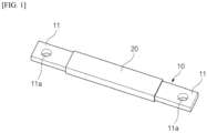
- FIG. 1 is a schematic diagram illustrating a structure of a bus bar of the related art.
- a bus bar 1 of the related art includes a bus bar conductor part 10 and a sheath layer 20 surrounding the bus bar conductor part 10.
- the bus bar conductor part 10 is, for example, a high-purity copper conductor part such as C1100 or a conductor part formed of a metal such as aluminum.
- the sheath layer 20 is formed of general silicone rubber or epoxy. The sheath layer 20 covers the body of the bus bar conductor part 10 excluding both ends 11 thereof. The both ends 11 of the bus bar conductor part 10 are provided with fastening holes 11a into which corresponding electrical connection parts are fastened.
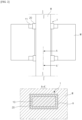
- FIG. 2 illustrates that battery modules M, which are to be installed in a battery pack, are electrically connected using the bus bar 1.
- the bus bar 1 is installed in a through-hole H of a partition W installed between the battery modules M, and the both ends 11 of the exposed metal conductor part 10 of the bus bar 1 are connected to module terminal parts at both sides of the partition wall.
- the temperature of the flames is very high (500 to 800 °C or 800 °C or higher, or 1000 °C or higher in severe cases), and thus, the sheath layer formed of silicone rubber or epoxy melts completely and the bus bar conductor part is exposed to the outside. In this case, the exposed bus bar conductor part comes into electrical contact with other metal parts in the battery pack, thus causing an electrical short circuit to occur, and the flames spread further due to heat generated due to the electrical short circuit.
- a bus bar including a sheath layer formed of mica sheet, glass fiber, heat-resistant silicone (rubber) or the like may be taken into account.
- a heat-resistant temperature of general heat-resistant silicone rubber is only in a range of 125 to 300 °C and thus a situation in which ignition occurs in a battery pack cannot be effectively coped with.
- the sheath layer formed of mica sheet or glass fiber does not exhibit sufficient fire-resistance performance.
- the present invention is directed to providing a fire-resistant bus bar for maintaining thermal and electrical insulation as long as possible even when flames occur in a battery pack.
- the present invention is also directed to providing a battery pack including the fire-resistant bus bar.
- a fire-resistant bus bar includes a bus bar conductor part, a sheath layer of a fire-resistant silicone covering portions of the bus bar conductor part excluding both ends thereof and ceramicized at high temperatures to support the bus bar conductor part, and a protective layer covering the sheath layer of the fire-resistant silicone, in which a metal sheet is included in the sheath layer of the fire-resistant silicone to reinforce structural rigidity of the sheath layer of the fire-resistant silicone.
- the fire-resistant silicone may be ceramicized at a temperature of 500 to 1700 °C.
- the fire-resistant silicone may be ceramicized by sintering a silicone resin containing a silicone compound represented by Chemical Formula 1 below and a metal oxide containing silicon oxide.
- n are each an integer of 10 to 30.
- the silicone resin and the metal oxide may be contained in a weight ratio of 1:0.5 to 1:1.5.
- the metal oxide containing silicon oxide may contain at least one of pure silicon dioxide, silica, quartz, silica stone, tridymite, and keatite.
- the metal sheet may be included in the sheath layer of the fire-resistant silicone to cover the bus bar conductor part while extending along the sheath layer of the fire-resistant silicone covering the bus bar conductor part.
- the sheath layer of the fire-resistant silicone may be provided between the inside of the metal sheet and the bus bar conductor part.
- the sheath layer of the fire-resistant silicone may be provided between the outside of the metal sheet and the protective layer. Portions of the sheath layer of the fire-resistant silicone inside and outside the metal sheet are coupled to each other through a through-hole formed in the metal sheet.
- the metal sheet may be molded together with the sheath layer of the fire-resistant silicone.
- the metal sheet may be provided with a plurality of through-holes, and the metal sheet and the sheath layer of the fire-resistant silicone may be integrally formed by injection-molding a fire-resistant silicone on upper and lower surfaces of the metal sheet to coat the upper and lower surfaces of the metal sheet with the fire-resistant silicone and fill the plurality of through-holes with the fire-resistant silicone.
- the bus bar conductor part may be coated with the sheath layer of the fire-resistant silicone by processing the metal sheet and the sheath layer of the fire-resistant silicone, which are integrally formed, in the form of a tape and winding the tape around the bus bar conductor part.
- the bus bar conductor part and the metal sheet are disposed in a mold, so that the metal sheet may be spaced apart from the bus bar conductor part while covering the bus bar conductor part, and the bus bar conductor part may be coated with the sheath layer of the fire-resistant silicone including the metal sheet by injection molding the fire-resistant silicone into the mold.
- the protective layer may be formed of glass fiber or mica.
- the fire-resistant bus bar may be a high-voltage bus bar for electrically connecting high-voltage terminal parts of a plurality of battery modules.
- a battery pack includes a plurality of battery modules, an anti-flame partition installed between the plurality of battery modules, the fire-resistant bus bar for electrically connecting the plurality of battery modules, and a pack housing accommodating the plurality of battery modules and the anti-flame partition.
- the anti-flame partition may be provided with a bus bar installation through-hole or a bus bar installation groove, the fire-resistant bus bar may be seated in the bus bar installation through-hole or the bus bar installation groove, and both ends of the fire-resistant bus bar may be electrically coupled to terminal parts of battery modules located at both sides of the anti-flame partition.
- a fire-resistant bus bar of the present invention includes a sheath layer of a fire-resistant silicone ceramicized to support a bus bar conductor part when flames occur in a pack instead of a sheath layer burned in flames, thus maintaining insulation and airtight characteristics even at high temperatures.
- the sheath layer of the fire-resistant silicone includes a metal sheet to reinforce the structural rigidity thereof, thereby preventing deformation due to an external force.
- the metal sheet maintains the insulation and shape of the bus bar and has a shielding function necessary for high voltage.
- the fire-resistant bus bar of the present invention include a protective layer to protect the sheath layer of the fire-resistant silicone.
- the protective layer may primarily function as a fire-resistant wall while preventing the sheath layer of the fire-resistant silicone from being directly exposed to flames, thereby maintaining an overall shape and dimensions.
- a fire-resistant bus bar of the present invention includes a bus bar conductor part, a sheath layer of a fire-resistant silicone that covers the bus bar conductor part excluding both ends of the bus bar conductor part and is ceramicized at high temperatures to support the bus bar conductor part, and a protective layer covering the sheath layer of the fire-resistant silicone, and a metal sheet is included in the sheath layer of the fire-resistant silicone to reinforce the structural rigidity of the sheath layer of the fire-resistant silicone.
- the bus bar conductor part may be a general metal conductor part. That is, the bus bar conductor part may be formed of a high-purity tough pitch copper material with purity of 99.9% or more, e.g., C1100, or an aluminum material. That is, a material of the bus bar conductor part of the present invention is not particularly limited as long as it is a metal material available as a bus bar conductor for connecting electrical components. The both ends of the bus bar conductor part are electrically connected to corresponding electrical connection parts.
- the sheath layer of the fire-resistant silicone is a layer applied to the bus bar conductor part while surrounding portions of the bus bar conductor part excluding both ends thereof. That is, the periphery of a central portion of the bus bar conductor part excluding the both ends is coated with the sheath layer of the fire-resistant silicone.
- the sheath layer of the fire-resistant silicone is ceramicized at high temperatures to support the bus bar conductor part.
- the fire-resistant silicone may be ceramicized at a temperature of 500 to 1700 °C.
- the fire-resistant silicone of the present invention with a fire-resistant temperature of 500 °C or higher is distinguished from a heat-resistant silicone with a heat-resistant temperature of less than 300 °C.
- the heat-resistant silicone is a silicone resin or rubber composition that is a material with flexibility and bendability that are characteristics of a silicone but is burned out or burned into ashes at a high temperature of 500 °C or higher. Therefore, there is a limit to applying the heat-resistant silicone to prevent a short circuit from occurring in a battery pack during heat propagation or prevent heat propagation.
- the sheath layer of the fire-resistant silicone is ceramicized, i.e., it exhibits "fire-resistant" performance, at a high temperature of 500 °C or higher, thereby maintaining insulation and airtightness characteristics in the battery pack even when flames occur.
- a fire-resistant bus bar according to the present invention exhibits high fire-resistant performance, because the fire-resistant bus bar includes a fire-resistant silicone and a structure thereof is improved.
- the fire-resistant silicone is a composition containing a silicone resin and a metal oxide as main components and thus exhibits flexibility and bendability, which are characteristics of a silicone, at room temperature.
- the fire-resistant silicone has a certain level of elasticity and thus exhibits high impact resistance and insulation, and a silicone sintered body with a complex ceramic structure may be formed due to sintering of the silicone resin and the metal oxide when the fire-resistant silicone is exposed to a high temperature.
- the silicone resin contained in the fire-resistant silicone produces silica in powder form when burned at a high temperature.
- the produced silica reacts with the metal oxide contained in the fire-resistant silicone to form an "eutectic mixture" on an edge of the metal oxide, so that bridging may be performed between the silica and the metal oxide, thus causing the formation of a ceramic product that is cured at an ignition temperature and condensed when cooled.
- Such a ceramic body prevents a short-circuit or disconnection between conductors due to damage to the sheath layer of the fire-resistant silicone even when external mechanical impact is applied or moisture penetrates in the case of a fire, thereby performing an electrical function of the bus bar.
- the fire-resistant silicone according to the present invention includes a silicone resin and a metal oxide.
- the silicone resin is not particularly limited as long as it is a resin containing silicon (Si) in a molecule but preferably contains a silicone compound represented by Chemical Formula 1 below (hereinafter referred to as a silicone compound of Chemical Formula 1).
- n are each an integer of 10 to 30.
- the silicone compound includes a methylsiloxane repeating unit, and includes a vinyl group at the inside of and an end of the methylsiloxane repeating unit.
- the vinyl group is contained in the repeating unit as well as at the end of the silicone compound of Chemical Formula 1 to increase a degree of polymerization of the silicone resin when exposed to a high temperature, thereby implementing excellent fire-resistance characteristics compared to a silicone compound that does not contain the vinyl group.
- the weight-average molecular weight of the silicone compound of Chemical Formula 1 may be adjusted to be in a specific range.
- the silicone compound of Chemical Formula 1 is a compound serving as a base of the silicone resin and thus may affect the physical properties of the fire-resistant silicone at room temperature and high temperatures according to the weight-average molecular weight of the silicone compound of Chemical Formula 1.
- the weight-average molecular weight of the silicone compound of Chemical Formula 1 is excessively high, the viscosity of the silicone resin increases and thus reactivity may decrease during high-temperature sintering, and when the weight-average molecular weight is extremely low, the elasticity and flexibility of the silicone resin at room temperature decrease, thus reducing the manufacturing processability, impact resistance, etc. of the fire-resistant bus bar.
- the weight-average molecular weight of the silicone compound of Chemical Formula 1 according to the present invention may be adjusted to be in a range of 1,000 to 9,000 g/mol, and specifically, a range of 3,000 to 8,000 g/mol or a range of 5,000 to 7,000 g/mol.
- the metal oxide is a composition containing silicon oxide and may function as a crystalline nucleus to form a high-density ceramic body together with the silicone resin described above when exposed to high temperatures.
- the metal oxide may include at least one of silicon dioxide, silica, quartz, silica stone, tridymite, and keatite.
- the metal oxide may include pure silicon dioxide (SiO 2 ) and a mineral, e.g., quartz, which contains silicon dioxide (SiO 2 ) as a main component, is economically feasible, has a high melting point (high fire-resistance) and a high sintering degree, and may exhibit excellent electrical insulation performance.
- silicon dioxide, silica, quartz, etc. may contribute to improving various performances in a sintering process, cause fire-resistant silicone to be easily dissolved and molded, and reduce defects that may occur in ceramic bodies.
- the metal oxide preferably has a crystal structure that increases fire resistance, insulation, mechanical strength, etc. when sintered together with a silicone resin.
- the metal oxide may be in the form of powder, and may have, but is not limited to, a size of 200 ⁇ m or less, for example, a size of 0.1 ⁇ m to 200 ⁇ m or a size of 0.1 ⁇ m to 100 ⁇ m.
- the silicone resin may further contain a silicone compound represented by Chemical Formula 2 below (hereinafter referred to as "silicone compound of Chemical Formula 2”), and the silicone compound of Chemical Formula 2 participates in the sintering of the metal oxide at a high temperature together with the silicone compound of Chemical Formula 1 to form a silicone sintered body.
- a silicone compound represented by Chemical Formula 2 below hereinafter referred to as "silicone compound of Chemical Formula 2”
- p is an integer of 10 to 30.
- the silicone compound of Chemical Formula 2 may increase the flexibility of the fire-resistant silicone at room temperature and induce the termination of the sintering of the silicone resin through dehydration condensation with the silicone compound of Chemical Formula 1 during sintering, thereby terminating the formation reaction of the ceramic body.
- the silicone compound of Chemical Formula 2 may be used in an amount of less than 10 parts by weight, for example, 0.5 to 9 parts by weight, 1 to 6 parts by weight, or 2 to 5 parts by weight, based on the 100 parts by weight of the fire-resistant silicone.
- the fire-resistant silicone may contain a silicone resin and a metal oxide in a certain ratio to realize high elasticity at room temperature and form a ceramic body quickly when exposed to high temperatures.
- a weight ratio between the silicone resin and the metal oxide may be 1:0.5 to 1:1.5, and specifically, 1:0.8 to 1:1.2.
- the weight ratio of the metal oxide is less than 0.5, it is difficult to obtain a ceramic structure having a high-density crystal structure at high temperatures and thus sufficient fire resistance and mechanical strength are not achieved.
- the weight ratio of the metal oxide exceeds 1.5, the flexibility of the fire-resistant silicone decreases at room temperature and thus the fire-resistant silicone is difficult to be processed.
- the fire-resistant silicone of the present invention may contain 35 to 50 wt% of the silicone compound of Chemical Formula 1, 16 to 32 wt% quartz, 10 to 27 wt% silicon dioxide, and 1 to 6 wt% of the silicone compound of Chemical Formula 2, and may further contain a certain solvent to increase processability during the manufacture of the fire-resistant silicone in some cases.
- the fire-resistant silicone of the present invention is cured and ceramicized by sintering the silicone resin and the metal oxide at 500 °C or higher.
- the fire-resistant silicone may be ceramicized at temperatures of up to 1700 °C, and theoretically can be kept partially ceramicized even at temperatures above 1700 °C. However, at a temperature above 1700 °C, a time period during which the fire-resistant silicone is kept ceramicized may decrease, thus causing a failure of the maintenance of fire-resistance performance required inside a battery pack.
- the fire-resistant silicone has the same properties as rubber having bendability, flexibility, and elasticity before being ceramicized. Therefore, the sheath layer of the fire-resistant silicone is easily injection-molded or applied to the bus bar conductor part as described below.
- the sheath layer of the fire-resistant silicone is flexible before being ceramicized and thus may flexibly follow deformation of the bus bar conductor part. Therefore, when the fire-resistant bus bar of the present invention is installed in the battery pack, it is possible to easily respond to even a slight assembly tolerance, thus improving assemblability. For example, when a battery module is fastened to the battery pack by bolting, the sheath layer of the fire-resistant silicone may absorb the movement or slight distortion of a bus bar conductor part coupled to the battery module. In addition, even when the battery pack vibrates due to the vibration of an electric vehicle, the sheath layer of the fire-resistant silicone may naturally absorb the vibration.
- the fire-resistant silicone when the fire-resistant silicone is ceramicized at a high temperature, the fire-resistant silicone is thermally and electrically insulated but the mechanical strength thereof decreases slightly and thus the fire-resistant silicone is likely to be broken by an external force.
- a metal sheet included in the sheath layer of the fire-resistant silicone and a protective layer covering the sheath layer of the fire-resistant silicone are provided.
- the protective layer is a layer covering the outside of the sheath layer of the fire-resistant silicone to protect the sheath layer of the fire-resistant silicone not to be directly exposed to flames. That is, the protective layer primarily functions as a fire-resistant wall. In addition, when the sheath layer of the fire-resistant silicone is ceramicized, the protective layer covers the ceramicized sheath layer to maintain an overall shape and dimensions thereof.
- a material of the protective layer may be, for example, glass fiber or mica material with insulating and heat resistance properties. That is, a glass fiber tape or mica tape may be wound around an outer side of the sheath layer of the fire-resistant silicone to prevent the sheath layer of the fire-resistant silicone from being exposed to the outside.
- the protective layer is not limited thereto and may be formed of a different material with excellent insulation or heat-resistance properties.
- a metal sheet is included in the sheath layer of the fire-resistant silicone to reinforce the rigidity of the sheath layer of the fire-resistant silicone.
- the metal sheet is included in the sheath layer of the fire-resistant silicone to function as a frame.
- the sheath layer of the fire-resistant silicone has bendability and flexibility and thus may be structurally weak before the sheath layer of the fire-resistant silicone is ceramicized. For example, even when the sheath layer of the fire-resistant silicone is coated or applied and cured on the bus bar conductor, the sheath layer of the fire-resistant silicone is likely to deform due to the properties of a material thereof. However, when the metal sheet is included in the sheath layer of the fire-resistant silicone, the metal sheet functions as a frame to structurally support the sheath layer of the fire-resistant silicone.
- the sheath layer of the fire-resistant silicone when the sheath layer of the fire-resistant silicone is ceramicized at a high temperature, the sheath layer of the fire-resistant silicone may brittle and thus mechanical strength thereof may decrease.
- a ceramicized silicone is structurally and firmly supported by the metal sheet, thus preventing the deformation of the sheath layer of the fire-resistant silicone due to an external force. Accordingly, the shape of the sheath layer of the fire-resistant silicone can be maintained, and the insulating function thereof can be stably maintained.
- the metal sheet is formed of a metal and thus may also have an electromagnetic shielding function when, for example, a fire-resistant bus bar is used as a high-voltage bus bar. Therefore, a fire-resistant bus bar of the present invention including the metal sheet therein may be appropriately used as a high-voltage bus bar.
- the metal sheet may be formed of a metal such as aluminum, steel, or stainless steel.
- the present invention is not limited thereto, and other materials that reinforce the rigidity of the sheath layer of the fire-resistant silicone and has the electromagnetic shielding function may be used.
- FIG. 3 is a perspective view and a cross-sectional view of a fire-resistant bus bar according to an embodiment of the present invention.
- a bus bar conductor part 110 is provided on an innermost side of a fire-resistant bus bar 100, and a covering part P is provided a part of a bus bar conductor part 110 excluding both ends 111.
- the both ends 111 of the bus bar conductor part 110 are exposed to the outside and provided with fastening holes 111a to combined with corresponding electrical connection parts (e.g., terminal parts).
- the covering part P includes a sheath layer 120 of a fire-resistant silicone covering the bus bar conductor part 110, and a protective layer 130 covering the sheath layer 120 of the fire-resistant silicone.
- a metal sheet 140 is included in the sheath layer 120 of the fire-resistant silicone.
- the sheath layer 120 of the fire-resistant silicone may be formed to be transparent or opaque according to a configuration of elements thereof.
- the sheath layer 120 of the fire-resistant silicone is illustrated to be transparent, so that the shape of the metal sheet 140 included therein may be clearly shown.
- the metal sheet 140 is included in the sheath layer 120 of the fire-resistant silicone to cover the bus bar conductor part 110 while extending along the sheath layer 120 of the fire-resistant silicone covering the bus bar conductor part 110. That is, the metal sheet 140 extends in the form of frame along the sheath layer 120 of the fire-resistant silicone.
- a thickness of the metal sheet 140 may be appropriately determined according to the thickness, composition, physical properties or the like of the sheath layer 120 of the fire-resistant silicone. In the case of a high-voltage bus bar, a thickness of the metal sheet 140 may be set to a thickness required to shield electromagnetic waves. For example, the metal sheet 140 may be manufactured to have a thickness of 0.3 mm to 3 mm.
- the metal sheet 140 and the busbar conductor part 110 are preferably separated from each other for insulation.
- the sheath layer 120 of the fire-resistant silicone is disposed (filled) between the metal sheet 140 and the bus bar conductor part 110.
- the sheath layer 120 of the fire-resistant silicone is provided between an outer side of the metal sheet 140 and the protective layer 130. Accordingly, the sheath layer 120 of the fire-resistant silicone is located inside and outside the metal sheet 140 with the metal sheet 140 as a boundary. In this case, the sheath layer 120 of the fire-resistant silicone inside and outside the metal sheet 140 may be blocked by the metal sheet 140.
- a through-hole 141 may be formed in the metal sheet 140.
- the parts of the sheath layer 120 of the fire-resistant silicone inside and outside the metal sheet 140 may be connected to each other through the through-hole 141.
- the metal sheet 140 and the parts of the sheath layer 120 of the fire-resistant silicone inside and outside the metal sheet 140 may be more firmly and integrally coupled to each other, thereby further improving the structural rigidity of the sheath layer 120 of the fire-resistant silicone. Therefore, when the sheath layer 120 of the fire-resistant silicone is ceramicized, the metal sheet 140 may support the sheath layer 120 of the fire-resistant silicone more firmly.
- a plurality of through-holes 141 may be formed in the metal sheet 140 to be spaced apart from each other.
- the through-hole 141 may have a circular shape, a quadrangular shape, or other shapes, and a size of the through-hole 141 may be appropriately selected.
- the metal sheet 140 may be molded together with the sheath layer 120 of the fire-resistant silicone.
- the molding of the sheath layer 120 of the fire-resistant silicone and a manufacturing process of the fire-resistant bus bar 100 of the present invention will be described in detail in the following embodiments.
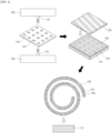
- FIG. 4 is a schematic diagram illustrating an example of a process of manufacturing the fire-resistant bus bar 100 of the present invention.
- the metal sheet 140 is molded together with the sheath layer 120 of the fire-resistant silicone.
- the metal sheet 140 includes, for example, a plurality of circular through-holes 141.
- a fire-resistant silicone may be injected toward the metal sheet 140 from nozzles 151 of fire-resistant silicone storage tanks 150 above and below the metal sheet 140.
- the fire-resistant silicone may be, for example, a mixture of a silicone resin and a metal oxide and be included in a certain solvent in the form of a coating solution or slurry with fluidity.
- a fire-resistant silicone coating solution is injected toward upper and lower surfaces of the metal sheet 140, the upper and lower surfaces of the metal sheet 140 are coated with the fire-resistant silicone and at the same time, the through-hole 141 is filled with the fire-resistant silicone.
- the fire-resistant silicones on the upper and lower surfaces of the metal sheet 140 are integrally coupled through the through-hole 141 of the metal sheet 140.
- the injection of the fire-resistant silicone may be performed in a certain mold and thus the metal sheet 140 and the fire-resistant silicone may be integrally manufactured by injection-molding.
- the sheath layer 120 of the fire-resistant silicone coated on the metal sheet 140 may have physical properties such as those of silicone rubber by drying and curing processes.
- the metal sheet 140 and the sheath layer 120 of the fire-resistant silicone that are integrally manufactured may be processed in the form of a tape.
- the bus bar conductor part 110 may be coated with the sheath layer 120 of the fire-resistant silicone by winding such a fire-resistant silicone coated tape around the bus bar conductor part 110.
- the fire-resistant bus bar 100 of the present invention may be manufactured by winding the protective layer 130, e.g., a glass fiber tape, around the sheath layer 120 of the fire-resistant silicone.
- the fire-resistant silicone coated tape may be wound around the bus bar conductor part 110 and a tape of the protective layer 130 may be wound around the fire-resistant silicone coated tape, but as shown in FIG. 4 , a covering part tape that forms the covering part P may be manufactured by attaching the tape of the protective layer 130 to the fire-resistant silicone coated tape.
- the fire-resistant bus bar 100 can be manufactured at once by winding the covering part tape around the bus bar conductor 110, thereby shortening a manufacturing process.
- the covering part P is in the form of a tape and thus the tape of the covering part P may be repeatedly wound around the bus bar conductor part 110, thereby further enhancing insulation and fire resistance.
- it is convenient to adjust insulation properties and fire resistance to meet design values by adjusting the number of turns of the covering part tape.
- the flexibility of the metal sheet 140 may decrease when processed in the form of a tape.
- the metal sheet 140 may be bent along a curvature of the sheath layer 120 of the fire-resistant silicone when the metal sheet 140 is very thin but may be difficult to be wound in the form of a tape when the metal sheet 140 is relatively thick.
- a shape of the metal sheet 140 is processed in advance to eliminate such manufacturing difficulties.
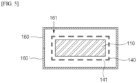
- FIG. 5 is a schematic diagram illustrating another example of a process of manufacturing the fire-resistant bus bar 100 of the present invention.
- the fire-resistant bus bar 100 is manufactured by disposing the metal sheet 140 and the bus bar conductor part 110 in a mold in advance and injecting the fire-resistant silicone into the mold by insert injection molding.
- the bus bar conductor part 110 and the metal sheet 140 are disposed in upper and lower molds 160 and 160' for insert-injection molding of FIG. 5 , so that the metal sheet 140 may be spaced apart from the bus bar conductor part 110 while surrounding the bus bar conductor part 110. Thereafter, a coating solution or slurry of the fire-resistant silicone is injected through injection holes 161 in the molds 160 and 160'. In this case, the fire-resistant silicone is filled between the metal sheet 140 and the bus bar conductor part 110 through the through-hole 141 of the metal sheet 140, and is also filled between an outer side of the metal sheet 140 and the molds 160 and 160'. As shown in FIG.
- a sheath layer including the bus bar conductor part 110 therein may be obtained by removing the molds 160 and 160' after drying and curing processes are performed. Thereafter, the tape of the protective layer 130 such as a glass fiber tape or mica tape may be wound around the sheath layer to obtain the fire-resistant bus bar 100 of the present invention.
- the tape of the protective layer 130 such as a glass fiber tape or mica tape may be wound around the sheath layer to obtain the fire-resistant bus bar 100 of the present invention.
- the metal sheet 140 is bent in advance to cover the bus bar conductor part 110, the metal sheet 140 that is relatively thick can be easily applied.
- the inside and outside of the metal sheet 140 can be simultaneously filled with the fire-resistant silicone through the through-hole 141 of the metal sheet 140, thereby simplifying a manufacturing process.
- a thickness of the sheath layer 120 of the fire-resistant silicone can be easily adjusted according to the size of a mold.
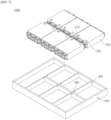
- FIG. 6 is a schematic view of an example of a structure of a battery pack in which a fire-resistant bus bar of the present invention is installed.
- FIG. 7 is a schematic view of another example of a structure of a battery pack in which a fire-resistant bus bar of the present invention is installed.
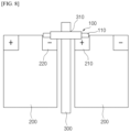
- FIG. 8 is a side cross-sectional view illustrating a state in which a fire-resistant bus bar of the present invention is installed in a battery pack.
- the above-described fire-resistant bus bar 100 of the present invention includes a sheath layer 120 of a fire-resistant silicone ceramicized at high temperatures, a protective layer 130 covering the sheath layer 120 of the fire-resistant silicone to maintain a shape, and a metal sheet 140 reinforcing the rigidity of the sheath layer 120 of the fire-resistant silicone. Therefore, when the fire-resistant bus bar 100 is applied to a battery pack in which ignition may occur, the safety of the battery pack can be greatly improved.
- the fire-resistant bus bar 100 may be used to electrically connect, for example, a plurality of battery modules accommodated in a battery pack. In this case, the fire-resistant bus bar 100 may electrically connect terminal parts of adj acent battery modules. Alternatively, the fire-resistant bus bar 100 may be used to connect battery modules to an external electrical device.
- the fire-resistant bus bar 100 of the present invention is applicable as a high-voltage bus bar for electrically connecting high-voltage terminal parts of a plurality of battery modules.
- the fire-resistant bus bar 100 includes the metal sheet 140 with an electromagnetic wave shielding function and thus is more suitable to be applied as a high-voltage bus bar in which the need for electromagnetic wave shielding is great.
- a battery pack 1000 of the present invention may include a plurality of battery modules 200, anti-flame partitions 300 installed between the battery modules 200, the above-described fire-resistant bus bar 100 for electrically connecting the battery modules 200, and a pack housing 400 accommodating the battery modules 200 and the anti-flame partitions 300.
- FIG. 6 illustrates that the plurality of battery modules 200 are accommodated in the pack housing 400.
- the battery modules 200 each include a cell stack (not shown) in which a plurality of battery cells are stacked, and cell leads with different polarities are drawn out from the battery cells of the cell stack.
- the cell leads are electrically connected to a bus bar such as a terminal bus bar or an inter-bus bar.
- the fire-resistant bus bar 100 of the present invention may be used to electrically connect the plurality of battery modules.
- FIGS. 6 and 7 illustrate a general battery module 200 in which a module housing completely surrounds upper, lower, left, and right sides of a battery cell stack.
- the fire-resistant bus bar 100 of the present invention is also applicable to a battery module with a moduleless type module housing in which at least one of upper, lower, left and right sides of a cell stack is open or a battery cell block in which all of upper, lower, left and right sides of a cell stack are open.
- a battery pack with a so-called cell-to-pack structure may be configured by installing therein cell blocks or battery modules, in which part of or an entire module housing is omitted.
- the fire-resistant bus bar 100 of the present invention may be used for electrical connection of cell blocks or moduleless type battery modules installed in such a battery pack having the cell-to-pack structure.
- the battery pack 1000 may include the anti-flame partitions 300 installed between battery modules.
- the anti-flame partitions 300 may be formed of a metal to secure rigidity.
- the anti-flame partitions 300 prevent flames from propagating to adjacent modules when a fire occurs in one module.
- the anti-flame partitions 300 may be each provided with a bus bar installation through-hole 310 or a bus bar installation groove 320.
- FIG. 6 illustrates that the anti-flame partition 300 is provided with the bus bar installation through-hole 310.
- FIG. 7 illustrates that the anti-flame partition 300 is provided with the bus bar installation groove 320.
- a partition is preferably provided with the bus bar installation through-hole 310 as shown in FIG. 6 .
- An upper part of the bus bar installation groove 320 of FIG. 7 is open, thus facilitating installation of a bus bar and an electrical connection using the bus bar.
- the fire-resistant bus bars 100 may be mounted in the bus bar installation through-hole 310 or the bus bar installation groove 320.
- both ends 111 of the bus bar conductor part 110 may be electrically coupled to terminal parts 210 and 220 of battery modules 200 located at both sides of the anti-flame partition 300.
- FIG. 8 illustrates that the fire-resistant bus bar 100 electrically connects the battery modules 200 in the battery pack 1000.
- the anti-flame partition 300 may be located between adjacent battery modules 200 and provided with the bus bar installation through-hole 310.
- the fire-resistant bus bar 100 of the present invention is inserted into the through-hole.
- a sheath layer 120 of a fire-resistant silicone surrounding the bus bar conductor part 110 is ceramicized, thus forming a dense sintered body. That is, at a high temperature of 500 °C or higher, the sheath layer 120 of the fire-resistant silicone is ceramicized and thus the shape thereof is maintained, unlike conventional heat-resistant silicone that is burned away or burned into ashes. Accordingly, the sheath layer 120 of the fire-resistant silicone stably supports the bus bar conductor part 110 even when a flame occurs.
- the metal sheet 140 reinforces the rigidity of the sheath layer 120 of the fire-resistant silicone to prevent the sheath layer 120 of the fire-resistant silicone from being broken.
- the protective layer 130 prevents the sheath layer 120 of the fire-resistant silicone from being in direct contact with flames, thus preventing the deformation of the fire-resistant silicone and further enhancing insulation and fire resistance.
- a fire-resistant silicone containing 50 parts by weight of the silicone compound of Chemical Formula 1, 20 parts by weight of quartz, and 30 parts by weight of pure silicon dioxide was applied to a certain thickness to a copper bus bar conductor part with a cross-sectional area, which is selected from a cross-sectional area that is in a range of 0.5 to 3 mm 2 , excluding both ends thereof.
- a fire-resistant silicone coated bus bar of Example 1 was manufactured by winding a 0.18 mm glass fiber tape (product name: AGTWO) manufactured by SWECO twice around a bus bar coated with the fire-resistant silicone.
- a bus bar of Comparative Example 1 was prepared by setting a length of a bus bar conductor part and exposed lengths of both ends of the bus bar conductor part to be the same as those of Example 1 and winding a glass fiber tape of AGTWO around a central portion of the bus bar conductor part. A thickness of covering of the wound glass fiber tape was set to be substantially the same as that of Example 1.
- a length of the bus bar conductor part and exposed lengths of both ends thereof are the same as those of Example 1 and Comparative Example 1.
- a copper wire was wound around a covering part of each of the bus bars of Examples 1 to Comparative Example 2 the same number of turns, one end of an outermost copper wire of the covering part was connected to a negative electrode terminal of a withstand voltage tester, and one end of each of the bus bar conductor parts was connected to a positive electrode terminal of the withstand voltage tester. Entire surfaces of the bus bars were uniformly heated by a large torch with a flame temperature of 1100 to 1150 °C while a voltage of 1000 V was applied to the bus bars by the withstand voltage tester.
- insulation characteristics of the fire-resistant bus bar of the present invention that includes the sheath layer of the fire-resistant silicone and the protective layer are excellent.
- insulation performance was tested without a metal sheet, and it is obvious that insulation performance will be further improved with respect to external high temperatures when the metal sheet is included in the sheath layer of the fire-resistant silicone.
- mechanical strength of the sheath layer of the fire-resistant silicone when ceramicized may increase and an electromagnetic wave shielding function may be additionally achieved.
- Fire-resistant silicones with compositions shown in Table 2 below were prepared while changing a weight ratio between the silicone compound of Chemical Formula 1 and a metal oxide.
- a fire-resistant silicone was applied to a certain thickness to a copper bus bar conductor part under the same conditions as in Experimental Example 1 and the glass fiber tape of AGTWO was wound around the sheath layer of the fire-resistant silicone.
- a copper wire was wound around the sheath layer of the fire-resistant silicone under the same conditions in Experimental Example 1 and connected to a withstand voltage tester. Heating was performed by a large torch under the same conditions as in Experimental Example 1 while a voltage was applied, and insulation fail times were measured. Measurement results are shown in Table 2 below.
- Example 1 50 parts by weight of silicone compound: 50 parts by weight of metal oxide (quartz: 20 parts by weight, pure silicon dioxide: 30 parts by weight 14 minutes
- Example 2 50 parts by weight of silicone compound: 25 parts by weight of metal oxide (quartz: 10 wt%, pure silicon dioxide: 15 wt%) 12 minutes and 50 seconds
- Example 3 50 parts by weight of silicone compound: 75 parts by weight of metal oxide 16 minutes (quartz: 30 parts by weight, pure silicon dioxide: 45 parts by weight
- Example 4 50 parts by weight of silicone compound: 20 parts by weight of metal oxide (quartz: 10 parts by weight, pure silicon dioxide: 10 parts by weight) 11 minutes
- Example 5 50 parts by weight of silicone compound: 80 parts by weight of metal oxide (quartz: 35 parts by weight, pure silicon dioxide: 45 parts by weight 16 minutes and 40 seconds
- weight ratios between the silicone compounds and the metal oxides were 1:1, 1:0.5, 1:1.5, 1:0.4, and 1:1.6.
- Example 4 in which the weight ratio of the metal oxide is less than 0.5, the insulation fail time was slightly short, and it is determined that the short insulation fail time was due to the generation of a slight insufficient amount of a ceramic structure having a high-density crystal structure at high temperatures due to an insufficient amount of the metal oxide.
- Example 5 In the case of Example 5 in which the weight ratio of the metal oxide is 1.6, the insulation fail time was sufficiently long but the amount of the metal oxide was excessive and thus the flexibility of the fire-resistant silicone decreased at room temperature, thus making it difficult to apply the fire-resistant silicone along the bus bar conductor part.
Landscapes
- Chemical & Material Sciences (AREA)
- Chemical Kinetics & Catalysis (AREA)
- General Chemical & Material Sciences (AREA)
- Electrochemistry (AREA)
- Engineering & Computer Science (AREA)
- Organic Chemistry (AREA)
- Manufacturing & Machinery (AREA)
- Mechanical Engineering (AREA)
- Health & Medical Sciences (AREA)
- Medicinal Chemistry (AREA)
- Polymers & Plastics (AREA)
- Inorganic Chemistry (AREA)
- Physics & Mathematics (AREA)
- Spectroscopy & Molecular Physics (AREA)
- Materials Engineering (AREA)
- Life Sciences & Earth Sciences (AREA)
- Wood Science & Technology (AREA)
- Battery Mounting, Suspending (AREA)
- Secondary Cells (AREA)
- Connection Of Batteries Or Terminals (AREA)
- Compositions Of Macromolecular Compounds (AREA)
- Paints Or Removers (AREA)
- Insulated Conductors (AREA)
Abstract
Description
- The present invention relates to a fire-resistant bus bar and a battery pack including the same.
- More specifically, the present invention relates to a fire-resistant bus bar including a sheath layer of a fire-resistant silicone ceramicized at high temperatures and a protective layer covering the sheath layer to maintain insulation and airtight properties even at high temperatures at which ignition occurs in a battery pack, and the battery pack.
- The present application claims the benefit of priority based on
Korean Patent Application No. 10-2022-0139401, filed on October 26, 2022 - A battery pack for use in electric vehicles, etc. has a structure in which a plurality of battery modules including a plurality of secondary batteries are connected in series or in parallel to obtain high power. The secondary batteries each include positive and negative current collectors, a separator, an active material, an electrolyte, etc. and thus can be repeatedly charged and discharged through an electrochemical reaction between these components.
- A bus bar is used to electrically connect the battery modules. The bus bar is used to electrically connect terminal parts of adjacent battery modules or to connect battery modules to an external electric device.
-
FIG. 1 is a schematic diagram illustrating a structure of a bus bar of the related art. - As shown in
FIG. 1 , abus bar 1 of the related art includes a busbar conductor part 10 and asheath layer 20 surrounding the busbar conductor part 10. The busbar conductor part 10 is, for example, a high-purity copper conductor part such as C1100 or a conductor part formed of a metal such as aluminum. Thesheath layer 20 is formed of general silicone rubber or epoxy. Thesheath layer 20 covers the body of the busbar conductor part 10 excluding both ends 11 thereof. The both ends 11 of the busbar conductor part 10 are provided withfastening holes 11a into which corresponding electrical connection parts are fastened. -
FIG. 2 illustrates that battery modules M, which are to be installed in a battery pack, are electrically connected using thebus bar 1. Thebus bar 1 is installed in a through-hole H of a partition W installed between the battery modules M, and the both ends 11 of the exposedmetal conductor part 10 of thebus bar 1 are connected to module terminal parts at both sides of the partition wall. - When in a battery pack, for example, battery modules are electrically connected using the
bus bar 1 of the related art, there is no problem with the operation of the battery pack at normal temperatures at which the battery pack operates normally. - However, when flames occur in the battery pack, the temperature of the flames is very high (500 to 800 °C or 800 °C or higher, or 1000 °C or higher in severe cases), and thus, the sheath layer formed of silicone rubber or epoxy melts completely and the bus bar conductor part is exposed to the outside. In this case, the exposed bus bar conductor part comes into electrical contact with other metal parts in the battery pack, thus causing an electrical short circuit to occur, and the flames spread further due to heat generated due to the electrical short circuit.
- To prevent thermal propagation, a bus bar including a sheath layer formed of mica sheet, glass fiber, heat-resistant silicone (rubber) or the like may be taken into account.
- However, in such a situation in which extremely high heat is generated, thermal propagation cannot be sufficiently prevented using the above-described materials. For example, a heat-resistant temperature of general heat-resistant silicone rubber is only in a range of 125 to 300 °C and thus a situation in which ignition occurs in a battery pack cannot be effectively coped with. In addition, the sheath layer formed of mica sheet or glass fiber does not exhibit sufficient fire-resistance performance.
- As described above, there have been recent demands to essentially design battery packs such that flames are prevented from leaking to the outside of the battery packs when ignition occurs in the battery packs.
- In addition, there is a need to design a bus bar conductor part to be thermally and electrically insulated from surroundings even at high temperatures when flames occur .
- As described above, it is necessary to develop a technique for improving an insulation level and assemblability while securing fire resistance at high temperatures to maintain electrical insulation.
-
Korean Patent Publication Laid-Open No. 10-2022-0001228 - The present invention is directed to providing a fire-resistant bus bar for maintaining thermal and electrical insulation as long as possible even when flames occur in a battery pack.
- The present invention is also directed to providing a battery pack including the fire-resistant bus bar.
- According to an aspect of the present invention, a fire-resistant bus bar includes a bus bar conductor part, a sheath layer of a fire-resistant silicone covering portions of the bus bar conductor part excluding both ends thereof and ceramicized at high temperatures to support the bus bar conductor part, and a protective layer covering the sheath layer of the fire-resistant silicone, in which a metal sheet is included in the sheath layer of the fire-resistant silicone to reinforce structural rigidity of the sheath layer of the fire-resistant silicone.
- The fire-resistant silicone may be ceramicized at a temperature of 500 to 1700 °C.
- The fire-resistant silicone may be ceramicized by sintering a silicone resin containing a silicone compound represented by Chemical Formula 1 below and a metal oxide containing silicon oxide.


- In
Chemical Formula 1, m and n are each an integer of 10 to 30. - The silicone resin and the metal oxide may be contained in a weight ratio of 1:0.5 to 1:1.5.
- The metal oxide containing silicon oxide may contain at least one of pure silicon dioxide, silica, quartz, silica stone, tridymite, and keatite.
- The metal sheet may be included in the sheath layer of the fire-resistant silicone to cover the bus bar conductor part while extending along the sheath layer of the fire-resistant silicone covering the bus bar conductor part.
- The sheath layer of the fire-resistant silicone may be provided between the inside of the metal sheet and the bus bar conductor part. The sheath layer of the fire-resistant silicone may be provided between the outside of the metal sheet and the protective layer. Portions of the sheath layer of the fire-resistant silicone inside and outside the metal sheet are coupled to each other through a through-hole formed in the metal sheet.
- The metal sheet may be molded together with the sheath layer of the fire-resistant silicone.
- The metal sheet may be provided with a plurality of through-holes, and the metal sheet and the sheath layer of the fire-resistant silicone may be integrally formed by injection-molding a fire-resistant silicone on upper and lower surfaces of the metal sheet to coat the upper and lower surfaces of the metal sheet with the fire-resistant silicone and fill the plurality of through-holes with the fire-resistant silicone.
- The bus bar conductor part may be coated with the sheath layer of the fire-resistant silicone by processing the metal sheet and the sheath layer of the fire-resistant silicone, which are integrally formed, in the form of a tape and winding the tape around the bus bar conductor part.
- In the fire-resistant bus bar of the present invention, the bus bar conductor part and the metal sheet are disposed in a mold, so that the metal sheet may be spaced apart from the bus bar conductor part while covering the bus bar conductor part, and the bus bar conductor part may be coated with the sheath layer of the fire-resistant silicone including the metal sheet by injection molding the fire-resistant silicone into the mold.
- The protective layer may be formed of glass fiber or mica.
- The fire-resistant bus bar may be a high-voltage bus bar for electrically connecting high-voltage terminal parts of a plurality of battery modules.
- According to another aspect of the present invention, a battery pack includes a plurality of battery modules, an anti-flame partition installed between the plurality of battery modules, the fire-resistant bus bar for electrically connecting the plurality of battery modules, and a pack housing accommodating the plurality of battery modules and the anti-flame partition.
- The anti-flame partition may be provided with a bus bar installation through-hole or a bus bar installation groove, the fire-resistant bus bar may be seated in the bus bar installation through-hole or the bus bar installation groove, and both ends of the fire-resistant bus bar may be electrically coupled to terminal parts of battery modules located at both sides of the anti-flame partition.
- A fire-resistant bus bar of the present invention includes a sheath layer of a fire-resistant silicone ceramicized to support a bus bar conductor part when flames occur in a pack instead of a sheath layer burned in flames, thus maintaining insulation and airtight characteristics even at high temperatures.
- The sheath layer of the fire-resistant silicone includes a metal sheet to reinforce the structural rigidity thereof, thereby preventing deformation due to an external force. The metal sheet maintains the insulation and shape of the bus bar and has a shielding function necessary for high voltage.
- The fire-resistant bus bar of the present invention include a protective layer to protect the sheath layer of the fire-resistant silicone. The protective layer may primarily function as a fire-resistant wall while preventing the sheath layer of the fire-resistant silicone from being directly exposed to flames, thereby maintaining an overall shape and dimensions.
-
-
FIG. 1 is a schematic diagram and a cross-sectional view of a structure of a bus bar of the related art. -
FIG. 2 is a schematic diagram illustrating an example in which battery modules are connected using a bus bar of the related art. -
FIG. 3 is a perspective view and a cross-sectional view of a fire-resistant bus bar according to an embodiment of the present invention. -
FIG. 4 is a schematic diagram illustrating an example of a process of manufacturing a fire-resistant bus bar of the present invention. -
FIG. 5 is a schematic diagram illustrating another example of a process of manufacturing a fire-resistant bus bar of the present invention. -
FIG. 6 is a schematic view of an example of a structure of a battery pack in which a fire-resistant bus bar of the present invention is installed. -
FIG. 7 is a schematic view of another example of a structure of a battery pack in which a fire-resistant bus bar of the present invention is installed. -
FIG. 8 is a side cross-sectional view illustrating a state in which a fire-resistant bus bar of the present invention is installed in a battery pack. - Hereinafter, a configuration of the present invention will be described in detail with reference to the accompanying drawings and various embodiments. Embodiments described below are provided as examples to help the understanding of the present invention, the accompanying drawings are not drawn on actual scale to help the understanding of the present invention, and the sizes of some components may be exaggerated.
- The present invention may be embodied in many different forms and implemented in various embodiments. Thus, certain embodiments are illustrated in the drawings and described in detail herein. It should be, however, understood that the present invention is not limited to particular embodiments and include all modifications, equivalents, and alternatives falling within the idea and scope of the present invention.
- A fire-resistant bus bar of the present invention includes a bus bar conductor part, a sheath layer of a fire-resistant silicone that covers the bus bar conductor part excluding both ends of the bus bar conductor part and is ceramicized at high temperatures to support the bus bar conductor part, and a protective layer covering the sheath layer of the fire-resistant silicone, and a metal sheet is included in the sheath layer of the fire-resistant silicone to reinforce the structural rigidity of the sheath layer of the fire-resistant silicone.
- The bus bar conductor part may be a general metal conductor part. That is, the bus bar conductor part may be formed of a high-purity tough pitch copper material with purity of 99.9% or more, e.g., C1100, or an aluminum material. That is, a material of the bus bar conductor part of the present invention is not particularly limited as long as it is a metal material available as a bus bar conductor for connecting electrical components. The both ends of the bus bar conductor part are electrically connected to corresponding electrical connection parts.
- The sheath layer of the fire-resistant silicone is a layer applied to the bus bar conductor part while surrounding portions of the bus bar conductor part excluding both ends thereof. That is, the periphery of a central portion of the bus bar conductor part excluding the both ends is coated with the sheath layer of the fire-resistant silicone. The sheath layer of the fire-resistant silicone is ceramicized at high temperatures to support the bus bar conductor part. The fire-resistant silicone may be ceramicized at a temperature of 500 to 1700 °C. The fire-resistant silicone of the present invention with a fire-resistant temperature of 500 °C or higher is distinguished from a heat-resistant silicone with a heat-resistant temperature of less than 300 °C. The heat-resistant silicone is a silicone resin or rubber composition that is a material with flexibility and bendability that are characteristics of a silicone but is burned out or burned into ashes at a high temperature of 500 °C or higher. Therefore, there is a limit to applying the heat-resistant silicone to prevent a short circuit from occurring in a battery pack during heat propagation or prevent heat propagation.
- The sheath layer of the fire-resistant silicone is ceramicized, i.e., it exhibits "fire-resistant" performance, at a high temperature of 500 °C or higher, thereby maintaining insulation and airtightness characteristics in the battery pack even when flames occur.
- As described above, a fire-resistant bus bar according to the present invention exhibits high fire-resistant performance, because the fire-resistant bus bar includes a fire-resistant silicone and a structure thereof is improved.
- The fire-resistant silicone is a composition containing a silicone resin and a metal oxide as main components and thus exhibits flexibility and bendability, which are characteristics of a silicone, at room temperature. In addition, the fire-resistant silicone has a certain level of elasticity and thus exhibits high impact resistance and insulation, and a silicone sintered body with a complex ceramic structure may be formed due to sintering of the silicone resin and the metal oxide when the fire-resistant silicone is exposed to a high temperature.
- Specifically, the silicone resin contained in the fire-resistant silicone produces silica in powder form when burned at a high temperature. The produced silica reacts with the metal oxide contained in the fire-resistant silicone to form an "eutectic mixture" on an edge of the metal oxide, so that bridging may be performed between the silica and the metal oxide, thus causing the formation of a ceramic product that is cured at an ignition temperature and condensed when cooled. Such a ceramic body prevents a short-circuit or disconnection between conductors due to damage to the sheath layer of the fire-resistant silicone even when external mechanical impact is applied or moisture penetrates in the case of a fire, thereby performing an electrical function of the bus bar.
- To this end, the fire-resistant silicone according to the present invention includes a silicone resin and a metal oxide.
- The silicone resin is not particularly limited as long as it is a resin containing silicon (Si) in a molecule but preferably contains a silicone compound represented by
Chemical Formula 1 below (hereinafter referred to as a silicone compound of Chemical Formula 1).
- In
Chemical Formula 1, m and n are each an integer of 10 to 30. - In
Chemical Formula 1, the silicone compound includes a methylsiloxane repeating unit, and includes a vinyl group at the inside of and an end of the methylsiloxane repeating unit. The vinyl group is contained in the repeating unit as well as at the end of the silicone compound ofChemical Formula 1 to increase a degree of polymerization of the silicone resin when exposed to a high temperature, thereby implementing excellent fire-resistance characteristics compared to a silicone compound that does not contain the vinyl group. - In addition, the weight-average molecular weight of the silicone compound of
Chemical Formula 1 may be adjusted to be in a specific range. The silicone compound ofChemical Formula 1 is a compound serving as a base of the silicone resin and thus may affect the physical properties of the fire-resistant silicone at room temperature and high temperatures according to the weight-average molecular weight of the silicone compound ofChemical Formula 1. For example, when the weight-average molecular weight of the silicone compound ofChemical Formula 1 is excessively high, the viscosity of the silicone resin increases and thus reactivity may decrease during high-temperature sintering, and when the weight-average molecular weight is extremely low, the elasticity and flexibility of the silicone resin at room temperature decrease, thus reducing the manufacturing processability, impact resistance, etc. of the fire-resistant bus bar. Therefore, the weight-average molecular weight of the silicone compound ofChemical Formula 1 according to the present invention may be adjusted to be in a range of 1,000 to 9,000 g/mol, and specifically, a range of 3,000 to 8,000 g/mol or a range of 5,000 to 7,000 g/mol. - In addition, the metal oxide is a composition containing silicon oxide and may function as a crystalline nucleus to form a high-density ceramic body together with the silicone resin described above when exposed to high temperatures.
- The metal oxide may include at least one of silicon dioxide, silica, quartz, silica stone, tridymite, and keatite. The metal oxide may include pure silicon dioxide (SiO2) and a mineral, e.g., quartz, which contains silicon dioxide (SiO2) as a main component, is economically feasible, has a high melting point (high fire-resistance) and a high sintering degree, and may exhibit excellent electrical insulation performance. In particular, silicon dioxide, silica, quartz, etc. may contribute to improving various performances in a sintering process, cause fire-resistant silicone to be easily dissolved and molded, and reduce defects that may occur in ceramic bodies.
- In addition, the metal oxide preferably has a crystal structure that increases fire resistance, insulation, mechanical strength, etc. when sintered together with a silicone resin. The metal oxide may be in the form of powder, and may have, but is not limited to, a size of 200 µm or less, for example, a size of 0.1 µm to 200 µm or a size of 0.1 µm to 100 µm.
- The silicone resin may further contain a silicone compound represented by Chemical Formula 2 below (hereinafter referred to as "silicone compound of Chemical Formula 2"), and the silicone compound of Chemical Formula 2 participates in the sintering of the metal oxide at a high temperature together with the silicone compound of
Chemical Formula 1 to form a silicone sintered body.
- In Chemical Formula 2 above, p is an integer of 10 to 30.
- The silicone compound of Chemical Formula 2 may increase the flexibility of the fire-resistant silicone at room temperature and induce the termination of the sintering of the silicone resin through dehydration condensation with the silicone compound of
Chemical Formula 1 during sintering, thereby terminating the formation reaction of the ceramic body. - To this end, the silicone compound of Chemical Formula 2 may be used in an amount of less than 10 parts by weight, for example, 0.5 to 9 parts by weight, 1 to 6 parts by weight, or 2 to 5 parts by weight, based on the 100 parts by weight of the fire-resistant silicone.
- In addition, the fire-resistant silicone may contain a silicone resin and a metal oxide in a certain ratio to realize high elasticity at room temperature and form a ceramic body quickly when exposed to high temperatures.
- Specifically, in the fire-resistant silicone, a weight ratio between the silicone resin and the metal oxide may be 1:0.5 to 1:1.5, and specifically, 1:0.8 to 1:1.2. When the weight ratio of the metal oxide is less than 0.5, it is difficult to obtain a ceramic structure having a high-density crystal structure at high temperatures and thus sufficient fire resistance and mechanical strength are not achieved. When the weight ratio of the metal oxide exceeds 1.5, the flexibility of the fire-resistant silicone decreases at room temperature and thus the fire-resistant silicone is difficult to be processed.
- For example, the fire-resistant silicone of the present invention may contain 35 to 50 wt% of the silicone compound of
Chemical Formula 1, 16 to 32 wt% quartz, 10 to 27 wt% silicon dioxide, and 1 to 6 wt% of the silicone compound of Chemical Formula 2, and may further contain a certain solvent to increase processability during the manufacture of the fire-resistant silicone in some cases. - As described above, the fire-resistant silicone of the present invention is cured and ceramicized by sintering the silicone resin and the metal oxide at 500 °C or higher. The fire-resistant silicone may be ceramicized at temperatures of up to 1700 °C, and theoretically can be kept partially ceramicized even at temperatures above 1700 °C. However, at a temperature above 1700 °C, a time period during which the fire-resistant silicone is kept ceramicized may decrease, thus causing a failure of the maintenance of fire-resistance performance required inside a battery pack.
- As described above, the fire-resistant silicone has the same properties as rubber having bendability, flexibility, and elasticity before being ceramicized. Therefore, the sheath layer of the fire-resistant silicone is easily injection-molded or applied to the bus bar conductor part as described below.
- The sheath layer of the fire-resistant silicone is flexible before being ceramicized and thus may flexibly follow deformation of the bus bar conductor part. Therefore, when the fire-resistant bus bar of the present invention is installed in the battery pack, it is possible to easily respond to even a slight assembly tolerance, thus improving assemblability. For example, when a battery module is fastened to the battery pack by bolting, the sheath layer of the fire-resistant silicone may absorb the movement or slight distortion of a bus bar conductor part coupled to the battery module. In addition, even when the battery pack vibrates due to the vibration of an electric vehicle, the sheath layer of the fire-resistant silicone may naturally absorb the vibration.
- Meanwhile, when the fire-resistant silicone is ceramicized at a high temperature, the fire-resistant silicone is thermally and electrically insulated but the mechanical strength thereof decreases slightly and thus the fire-resistant silicone is likely to be broken by an external force. In the present invention, in order to structurally improve the rigidity of the sheath layer of the fire-resistant silicone, a metal sheet included in the sheath layer of the fire-resistant silicone and a protective layer covering the sheath layer of the fire-resistant silicone are provided.
- The protective layer is a layer covering the outside of the sheath layer of the fire-resistant silicone to protect the sheath layer of the fire-resistant silicone not to be directly exposed to flames. That is, the protective layer primarily functions as a fire-resistant wall. In addition, when the sheath layer of the fire-resistant silicone is ceramicized, the protective layer covers the ceramicized sheath layer to maintain an overall shape and dimensions thereof.
- A material of the protective layer may be, for example, glass fiber or mica material with insulating and heat resistance properties. That is, a glass fiber tape or mica tape may be wound around an outer side of the sheath layer of the fire-resistant silicone to prevent the sheath layer of the fire-resistant silicone from being exposed to the outside. However, the protective layer is not limited thereto and may be formed of a different material with excellent insulation or heat-resistance properties.
- A metal sheet is included in the sheath layer of the fire-resistant silicone to reinforce the rigidity of the sheath layer of the fire-resistant silicone. The metal sheet is included in the sheath layer of the fire-resistant silicone to function as a frame. The sheath layer of the fire-resistant silicone has bendability and flexibility and thus may be structurally weak before the sheath layer of the fire-resistant silicone is ceramicized. For example, even when the sheath layer of the fire-resistant silicone is coated or applied and cured on the bus bar conductor, the sheath layer of the fire-resistant silicone is likely to deform due to the properties of a material thereof. However, when the metal sheet is included in the sheath layer of the fire-resistant silicone, the metal sheet functions as a frame to structurally support the sheath layer of the fire-resistant silicone.
- Particularly, when the sheath layer of the fire-resistant silicone is ceramicized at a high temperature, the sheath layer of the fire-resistant silicone may brittle and thus mechanical strength thereof may decrease. In this case, a ceramicized silicone is structurally and firmly supported by the metal sheet, thus preventing the deformation of the sheath layer of the fire-resistant silicone due to an external force. Accordingly, the shape of the sheath layer of the fire-resistant silicone can be maintained, and the insulating function thereof can be stably maintained. In addition, the metal sheet is formed of a metal and thus may also have an electromagnetic shielding function when, for example, a fire-resistant bus bar is used as a high-voltage bus bar. Therefore, a fire-resistant bus bar of the present invention including the metal sheet therein may be appropriately used as a high-voltage bus bar.
- The metal sheet may be formed of a metal such as aluminum, steel, or stainless steel. However, the present invention is not limited thereto, and other materials that reinforce the rigidity of the sheath layer of the fire-resistant silicone and has the electromagnetic shielding function may be used.
- Shapes of the fire-resistant bus bar and the metal sheet will be described in detail with respect to the following embodiments.
-
FIG. 3 is a perspective view and a cross-sectional view of a fire-resistant bus bar according to an embodiment of the present invention. - As illustrated in
FIG. 3 , a busbar conductor part 110 is provided on an innermost side of a fire-resistant bus bar 100, and a covering part P is provided a part of a busbar conductor part 110 excluding both ends 111. The both ends 111 of the busbar conductor part 110 are exposed to the outside and provided withfastening holes 111a to combined with corresponding electrical connection parts (e.g., terminal parts). - The covering part P includes a
sheath layer 120 of a fire-resistant silicone covering the busbar conductor part 110, and aprotective layer 130 covering thesheath layer 120 of the fire-resistant silicone. Ametal sheet 140 is included in thesheath layer 120 of the fire-resistant silicone. - The
sheath layer 120 of the fire-resistant silicone may be formed to be transparent or opaque according to a configuration of elements thereof. In the perspective view ofFIG. 3 , thesheath layer 120 of the fire-resistant silicone is illustrated to be transparent, so that the shape of themetal sheet 140 included therein may be clearly shown. - As shown in
FIG. 3 , themetal sheet 140 is included in thesheath layer 120 of the fire-resistant silicone to cover the busbar conductor part 110 while extending along thesheath layer 120 of the fire-resistant silicone covering the busbar conductor part 110. That is, themetal sheet 140 extends in the form of frame along thesheath layer 120 of the fire-resistant silicone. A thickness of themetal sheet 140 may be appropriately determined according to the thickness, composition, physical properties or the like of thesheath layer 120 of the fire-resistant silicone. In the case of a high-voltage bus bar, a thickness of themetal sheet 140 may be set to a thickness required to shield electromagnetic waves. For example, themetal sheet 140 may be manufactured to have a thickness of 0.3 mm to 3 mm. - The
metal sheet 140 and thebusbar conductor part 110 are preferably separated from each other for insulation. In this case, as shown in the cross-sectional view ofFIG. 3 , thesheath layer 120 of the fire-resistant silicone is disposed (filled) between themetal sheet 140 and the busbar conductor part 110. In addition, thesheath layer 120 of the fire-resistant silicone is provided between an outer side of themetal sheet 140 and theprotective layer 130. Accordingly, thesheath layer 120 of the fire-resistant silicone is located inside and outside themetal sheet 140 with themetal sheet 140 as a boundary. In this case, thesheath layer 120 of the fire-resistant silicone inside and outside themetal sheet 140 may be blocked by themetal sheet 140. However, in order to strengthen the combination of themetal sheet 140 and thesheath layer 120 of the fire-resistant silicone, it is more desirable to connect parts of thesheath layer 120 of the fire-resistant silicone inside and outside the metal sheet through themetal sheet 140. - To this end, as shown in
FIG. 3 , a through-hole 141 may be formed in themetal sheet 140. In this case, the parts of thesheath layer 120 of the fire-resistant silicone inside and outside themetal sheet 140 may be connected to each other through the through-hole 141. In this case, themetal sheet 140 and the parts of thesheath layer 120 of the fire-resistant silicone inside and outside themetal sheet 140 may be more firmly and integrally coupled to each other, thereby further improving the structural rigidity of thesheath layer 120 of the fire-resistant silicone. Therefore, when thesheath layer 120 of the fire-resistant silicone is ceramicized, themetal sheet 140 may support thesheath layer 120 of the fire-resistant silicone more firmly. A plurality of through-holes 141 may be formed in themetal sheet 140 to be spaced apart from each other. The through-hole 141 may have a circular shape, a quadrangular shape, or other shapes, and a size of the through-hole 141 may be appropriately selected. - The
metal sheet 140 may be molded together with thesheath layer 120 of the fire-resistant silicone. The molding of thesheath layer 120 of the fire-resistant silicone and a manufacturing process of the fire-resistant bus bar 100 of the present invention will be described in detail in the following embodiments. -
FIG. 4 is a schematic diagram illustrating an example of a process of manufacturing the fire-resistant bus bar 100 of the present invention. - In the present embodiment, the
metal sheet 140 is molded together with thesheath layer 120 of the fire-resistant silicone. - The
metal sheet 140 includes, for example, a plurality of circular through-holes 141. A fire-resistant silicone may be injected toward themetal sheet 140 fromnozzles 151 of fire-resistantsilicone storage tanks 150 above and below themetal sheet 140. As described above, the fire-resistant silicone may be, for example, a mixture of a silicone resin and a metal oxide and be included in a certain solvent in the form of a coating solution or slurry with fluidity. When such a fire-resistant silicone coating solution is injected toward upper and lower surfaces of themetal sheet 140, the upper and lower surfaces of themetal sheet 140 are coated with the fire-resistant silicone and at the same time, the through-hole 141 is filled with the fire-resistant silicone. In this case, the fire-resistant silicones on the upper and lower surfaces of themetal sheet 140 are integrally coupled through the through-hole 141 of themetal sheet 140. The injection of the fire-resistant silicone may be performed in a certain mold and thus themetal sheet 140 and the fire-resistant silicone may be integrally manufactured by injection-molding. Thesheath layer 120 of the fire-resistant silicone coated on themetal sheet 140 may have physical properties such as those of silicone rubber by drying and curing processes. - As shown in
FIG. 4 , themetal sheet 140 and thesheath layer 120 of the fire-resistant silicone that are integrally manufactured may be processed in the form of a tape. The busbar conductor part 110 may be coated with thesheath layer 120 of the fire-resistant silicone by winding such a fire-resistant silicone coated tape around the busbar conductor part 110. Next, the fire-resistant bus bar 100 of the present invention may be manufactured by winding theprotective layer 130, e.g., a glass fiber tape, around thesheath layer 120 of the fire-resistant silicone. - The fire-resistant silicone coated tape may be wound around the bus
bar conductor part 110 and a tape of theprotective layer 130 may be wound around the fire-resistant silicone coated tape, but as shown inFIG. 4 , a covering part tape that forms the covering part P may be manufactured by attaching the tape of theprotective layer 130 to the fire-resistant silicone coated tape. In this case, the fire-resistant bus bar 100 can be manufactured at once by winding the covering part tape around thebus bar conductor 110, thereby shortening a manufacturing process. - In the present embodiment, the covering part P is in the form of a tape and thus the tape of the covering part P may be repeatedly wound around the bus
bar conductor part 110, thereby further enhancing insulation and fire resistance. In addition, it is convenient to adjust insulation properties and fire resistance to meet design values by adjusting the number of turns of the covering part tape. - However, in the case of the present embodiment, the flexibility of the
metal sheet 140 may decrease when processed in the form of a tape. Themetal sheet 140 may be bent along a curvature of thesheath layer 120 of the fire-resistant silicone when themetal sheet 140 is very thin but may be difficult to be wound in the form of a tape when themetal sheet 140 is relatively thick. In the following embodiment, a shape of themetal sheet 140 is processed in advance to eliminate such manufacturing difficulties. -
FIG. 5 is a schematic diagram illustrating another example of a process of manufacturing the fire-resistant bus bar 100 of the present invention. - In the present embodiment, the fire-
resistant bus bar 100 is manufactured by disposing themetal sheet 140 and the busbar conductor part 110 in a mold in advance and injecting the fire-resistant silicone into the mold by insert injection molding. - The bus
bar conductor part 110 and themetal sheet 140 are disposed in upper andlower molds 160 and 160' for insert-injection molding ofFIG. 5 , so that themetal sheet 140 may be spaced apart from the busbar conductor part 110 while surrounding the busbar conductor part 110. Thereafter, a coating solution or slurry of the fire-resistant silicone is injected throughinjection holes 161 in themolds 160 and 160'. In this case, the fire-resistant silicone is filled between themetal sheet 140 and the busbar conductor part 110 through the through-hole 141 of themetal sheet 140, and is also filled between an outer side of themetal sheet 140 and themolds 160 and 160'. As shown inFIG. 3 , a sheath layer including the busbar conductor part 110 therein may be obtained by removing themolds 160 and 160' after drying and curing processes are performed. Thereafter, the tape of theprotective layer 130 such as a glass fiber tape or mica tape may be wound around the sheath layer to obtain the fire-resistant bus bar 100 of the present invention. - In the present embodiment, the
metal sheet 140 is bent in advance to cover the busbar conductor part 110, themetal sheet 140 that is relatively thick can be easily applied. The inside and outside of themetal sheet 140 can be simultaneously filled with the fire-resistant silicone through the through-hole 141 of themetal sheet 140, thereby simplifying a manufacturing process. In addition, a thickness of thesheath layer 120 of the fire-resistant silicone can be easily adjusted according to the size of a mold. -
FIG. 6 is a schematic view of an example of a structure of a battery pack in which a fire-resistant bus bar of the present invention is installed.FIG. 7 is a schematic view of another example of a structure of a battery pack in which a fire-resistant bus bar of the present invention is installed.FIG. 8 is a side cross-sectional view illustrating a state in which a fire-resistant bus bar of the present invention is installed in a battery pack. - The above-described fire-
resistant bus bar 100 of the present invention includes asheath layer 120 of a fire-resistant silicone ceramicized at high temperatures, aprotective layer 130 covering thesheath layer 120 of the fire-resistant silicone to maintain a shape, and ametal sheet 140 reinforcing the rigidity of thesheath layer 120 of the fire-resistant silicone. Therefore, when the fire-resistant bus bar 100 is applied to a battery pack in which ignition may occur, the safety of the battery pack can be greatly improved. - The fire-
resistant bus bar 100 may be used to electrically connect, for example, a plurality of battery modules accommodated in a battery pack. In this case, the fire-resistant bus bar 100 may electrically connect terminal parts of adj acent battery modules. Alternatively, the fire-resistant bus bar 100 may be used to connect battery modules to an external electrical device. - Particularly, high-voltage terminal parts of the battery modules generate relatively high heat due to a high current. Accordingly, higher heat may be concentrated on the high-voltage terminal parts when flames occur in the pack. Therefore, the fire-
resistant bus bar 100 of the present invention is applicable as a high-voltage bus bar for electrically connecting high-voltage terminal parts of a plurality of battery modules. In addition, the fire-resistant bus bar 100 includes themetal sheet 140 with an electromagnetic wave shielding function and thus is more suitable to be applied as a high-voltage bus bar in which the need for electromagnetic wave shielding is great. - A
battery pack 1000 of the present invention may include a plurality ofbattery modules 200,anti-flame partitions 300 installed between thebattery modules 200, the above-described fire-resistant bus bar 100 for electrically connecting thebattery modules 200, and apack housing 400 accommodating thebattery modules 200 and theanti-flame partitions 300. -
FIG. 6 illustrates that the plurality ofbattery modules 200 are accommodated in thepack housing 400. Thebattery modules 200 each include a cell stack (not shown) in which a plurality of battery cells are stacked, and cell leads with different polarities are drawn out from the battery cells of the cell stack. The cell leads are electrically connected to a bus bar such as a terminal bus bar or an inter-bus bar. The fire-resistant bus bar 100 of the present invention may be used to electrically connect the plurality of battery modules. - Meanwhile,
FIGS. 6 and7 illustrate ageneral battery module 200 in which a module housing completely surrounds upper, lower, left, and right sides of a battery cell stack. However, the present invention is not limited thereto, and the fire-resistant bus bar 100 of the present invention is also applicable to a battery module with a moduleless type module housing in which at least one of upper, lower, left and right sides of a cell stack is open or a battery cell block in which all of upper, lower, left and right sides of a cell stack are open. As described above, a battery pack with a so-called cell-to-pack structure may be configured by installing therein cell blocks or battery modules, in which part of or an entire module housing is omitted. The fire-resistant bus bar 100 of the present invention may be used for electrical connection of cell blocks or moduleless type battery modules installed in such a battery pack having the cell-to-pack structure. - In order to prevent flame propagation between adj acent modules, the
battery pack 1000 may include theanti-flame partitions 300 installed between battery modules. Theanti-flame partitions 300 may be formed of a metal to secure rigidity. Theanti-flame partitions 300 prevent flames from propagating to adjacent modules when a fire occurs in one module. In this case, theanti-flame partitions 300 may be each provided with a bus bar installation through-hole 310 or a busbar installation groove 320.FIG. 6 illustrates that theanti-flame partition 300 is provided with the bus bar installation through-hole 310.FIG. 7 illustrates that theanti-flame partition 300 is provided with the busbar installation groove 320. In terms of flame prevention and airtightness, a partition is preferably provided with the bus bar installation through-hole 310 as shown inFIG. 6 . An upper part of the busbar installation groove 320 ofFIG. 7 is open, thus facilitating installation of a bus bar and an electrical connection using the bus bar. - The fire-resistant bus bars 100 may be mounted in the bus bar installation through-
hole 310 or the busbar installation groove 320. In this case, both ends 111 of the busbar conductor part 110 may be electrically coupled toterminal parts battery modules 200 located at both sides of theanti-flame partition 300. -
FIG. 8 illustrates that the fire-resistant bus bar 100 electrically connects thebattery modules 200 in thebattery pack 1000. Theanti-flame partition 300 may be located betweenadjacent battery modules 200 and provided with the bus bar installation through-hole 310. The fire-resistant bus bar 100 of the present invention is inserted into the through-hole. - Meanwhile, when a flame occurs in the
battery pack 1000, in a fire-resistant bus bar of the present invention, asheath layer 120 of a fire-resistant silicone surrounding the busbar conductor part 110 is ceramicized, thus forming a dense sintered body. That is, at a high temperature of 500 °C or higher, thesheath layer 120 of the fire-resistant silicone is ceramicized and thus the shape thereof is maintained, unlike conventional heat-resistant silicone that is burned away or burned into ashes. Accordingly, thesheath layer 120 of the fire-resistant silicone stably supports the busbar conductor part 110 even when a flame occurs. In this case, themetal sheet 140 reinforces the rigidity of thesheath layer 120 of the fire-resistant silicone to prevent thesheath layer 120 of the fire-resistant silicone from being broken. In addition, theprotective layer 130 prevents thesheath layer 120 of the fire-resistant silicone from being in direct contact with flames, thus preventing the deformation of the fire-resistant silicone and further enhancing insulation and fire resistance. - A fire-resistant silicone containing 50 parts by weight of the silicone compound of
Chemical Formula - A bus bar of Comparative Example 1 was prepared by setting a length of a bus bar conductor part and exposed lengths of both ends of the bus bar conductor part to be the same as those of Example 1 and winding a glass fiber tape of AGTWO around a central portion of the bus bar conductor part. A thickness of covering of the wound glass fiber tape was set to be substantially the same as that of Example 1.
- To manufacture a bus bar of Comparative Example 2, a mica tape formed of phlogopite mica, which is a natural mica, was wound around a central portion of a bus bar conductor part and the glass fiber tape of AGTWO was wound around the mica tape. A length of the bus bar conductor part and exposed lengths of both ends thereof are the same as those of Example 1 and Comparative Example 1.
- To test insulation characteristics (insulation maintenance performance) when a fire occurs, a copper wire was wound around a covering part of each of the bus bars of Examples 1 to Comparative Example 2 the same number of turns, one end of an outermost copper wire of the covering part was connected to a negative electrode terminal of a withstand voltage tester, and one end of each of the bus bar conductor parts was connected to a positive electrode terminal of the withstand voltage tester. Entire surfaces of the bus bars were uniformly heated by a large torch with a flame temperature of 1100 to 1150 °C while a voltage of 1000 V was applied to the bus bars by the withstand voltage tester.
- An insulation failure time during which an insulation state is destroyed, i.e., a short circuit occurs, was measured under the above-described voltage and heating temperature conditions, and measurement results are shown in Table 1 below.
[Table 1] Experimental Example 1 Configuration of Bus Bar Insulation Fail Time Comparative Example 1 copper bus bar conductor part+ glass fiber tape 1 minute and 35 seconds Comparative Example 2 copper bus bar conductor part+mica tape+ glass fiber tape 10 minutes Example 1 copper bus bar conductor part+sheath layer of fire-resistant silicone+glass fiber tape 14 minutes - As shown in Table 1, an insulation fail time of the bus bar with a sheath layer of the present invention was longest and showed a significant difference from those of Comparative Examples 1 and 2.
- Therefore, it can be seen that insulation characteristics of the fire-resistant bus bar of the present invention that includes the sheath layer of the fire-resistant silicone and the protective layer are excellent. In Example 1, insulation performance was tested without a metal sheet, and it is obvious that insulation performance will be further improved with respect to external high temperatures when the metal sheet is included in the sheath layer of the fire-resistant silicone. In addition, when the metal sheet is installed, mechanical strength of the sheath layer of the fire-resistant silicone when ceramicized may increase and an electromagnetic wave shielding function may be additionally achieved.
- Fire-resistant silicones with compositions shown in Table 2 below were prepared while changing a weight ratio between the silicone compound of
Chemical Formula 1 and a metal oxide. - A fire-resistant silicone was applied to a certain thickness to a copper bus bar conductor part under the same conditions as in Experimental Example 1 and the glass fiber tape of AGTWO was wound around the sheath layer of the fire-resistant silicone.
- A copper wire was wound around the sheath layer of the fire-resistant silicone under the same conditions in Experimental Example 1 and connected to a withstand voltage tester. Heating was performed by a large torch under the same conditions as in Experimental Example 1 while a voltage was applied, and insulation fail times were measured. Measurement results are shown in Table 2 below.
[Table 2] Experimental Example 2 Composition of Sheath Layer of Fire-Resistant Silicone Insulation Fail Time Example 1 50 parts by weight of silicone compound: 50 parts by weight of metal oxide (quartz: 20 parts by weight, pure silicon dioxide: 30 parts by weight 14 minutes Example 2 50 parts by weight of silicone compound: 25 parts by weight of metal oxide (quartz: 10 wt%, pure silicon dioxide: 15 wt%) 12 minutes and 50 seconds Example 3 50 parts by weight of silicone compound: 75 parts by weight of metal oxide 16 minutes (quartz: 30 parts by weight, pure silicon dioxide: 45 parts by weight Example 4 50 parts by weight of silicone compound: 20 parts by weight of metal oxide (quartz: 10 parts by weight, pure silicon dioxide: 10 parts by weight) 11 minutes Example 5 50 parts by weight of silicone compound: 80 parts by weight of metal oxide (quartz: 35 parts by weight, pure silicon dioxide: 45 parts by weight 16 minutes and 40 seconds - In Examples 1 to 5 above, weight ratios between the silicone compounds and the metal oxides were 1:1, 1:0.5, 1:1.5, 1:0.4, and 1:1.6.
- The insulation fail times of all of the Examples were longer than those of Comparative Examples 1 and 2 above. However, in the case of Example 4 in which the weight ratio of the metal oxide is less than 0.5, the insulation fail time was slightly short, and it is determined that the short insulation fail time was due to the generation of a slight insufficient amount of a ceramic structure having a high-density crystal structure at high temperatures due to an insufficient amount of the metal oxide.
- In the case of Example 5 in which the weight ratio of the metal oxide is 1.6, the insulation fail time was sufficiently long but the amount of the metal oxide was excessive and thus the flexibility of the fire-resistant silicone decreased at room temperature, thus making it difficult to apply the fire-resistant silicone along the bus bar conductor part.
- The present invention has been described above in more detail with reference to the drawings, the embodiments, etc. However, the configurations illustrated in the drawings or embodiments described in the present specification are only embodiments of the present invention and do not reflect all the technical ideas of the present invention and thus it should be understood that various equivalents and modifications that replace the configurations would have been made at the filing date of the present application.
-
- 100: fire-resistant bus bar
- 110: bus bar conductor part
- 120: sheath layer of fire-resistant silicone
- 130: protective layer
- 140: metal sheet
- 141: through-hole
- 150: fire-resistant silicone storage tank
- 160, 160': upper and lower molds
- 200: battery module
- 210, 220: terminal part
- 300: anti-flame partition
- 310: bus bar installation through-hole
- 320: bus bar installation groove
- 400: pack housing
- 1000: battery pack
Claims (15)
- A fire-resistant bus bar comprising:a bus bar conductor part;a sheath layer of a fire-resistant silicone covering portions of the bus bar conductor part excluding both ends and ceramicized at high temperatures to support the bus bar conductor part; anda protective layer covering the sheath layer of the fire-resistant silicone,wherein a metal sheet is included in the sheath layer of the fire-resistant silicone to reinforce structural rigidity of the sheath layer of the fire-resistant silicone.
- The fire-resistant bus bar of claim 1, wherein the fire-resistant silicone is ceramicized at a temperature of 500 to 1700 °C.
- The fire-resistant bus bar of claim 1, wherein the fire-resistant silicone is ceramicized by sintering a silicone resin containing a silicone compound represented by Chemical Formula 1 below and a metal oxide containing silicon oxide, wherein:

- The fire-resistant bus bar of claim 3, wherein the silicone resin and the metal oxide are contained in a weight ratio of 1:0.5 to 1:1.5.
- The fire-resistant bus bar of claim 3, wherein the metal oxide containing silicon oxide comprises at least one of pure silicon dioxide, silica, quartz, silica stone, tridymite, and keatite.
- The fire-resistant bus bar of claim 1, wherein the metal sheet is included in the sheath layer of the fire-resistant silicone to cover the bus bar conductor part while extending along the sheath layer of the fire-resistant silicone covering the bus bar conductor part.
- The fire-resistant bus bar of claim 6, wherein the sheath layer of the fire-resistant silicone is provided between the inside of the metal sheet and the bus bar conductor part,the sheath layer of the fire-resistant silicone is provided between the outside of the metal sheet and the protective layer, andportions of the sheath layer of the fire-resistant silicone inside and outside the metal sheet are coupled to each other through a through-hole formed in the metal sheet.
- The fire-resistant bus bar of claim 1, wherein the metal sheet is molded together with the sheath layer of the fire-resistant silicone.
- The fire-resistant bus bar of claim 8, wherein the metal sheet is provided with a plurality of through-holes, and
the metal sheet and the sheath layer of the fire-resistant silicone are integrally formed by injection-molding a fire-resistant silicone on upper and lower surfaces of the metal sheet to coat the upper and lower surfaces of the metal sheet with the fire-resistant silicone and fill the plurality of through-holes with the fire-resistant silicone. - The fire-resistant bus bar of claim 9, wherein the bus bar conductor part is coated with the sheath layer of the fire-resistant silicone by processing the metal sheet and the sheath layer of the fire-resistant silicone, which are integrally formed, in the form of a tape and winding the tape around the bus bar conductor part.
- The fire-resistant bus bar of claim 8, wherein the bus bar conductor part and the metal sheet are disposed in a mold, wherein the metal sheet is spaced apart from the bus bar conductor part while covering the bus bar conductor part, and
the bus bar conductor part is coated with the sheath layer of the fire-resistant silicone including metal sheet by injection molding the fire-resistant silicone into the mold. - The fire-resistant bus bar of claim 1, wherein
the protective layer is formed of glass fiber or mica. - The fire-resistant bus bar of claim 1, wherein the fire-resistant bus bar is a high-voltage bus bar for electrically connecting high-voltage terminal parts of a plurality of battery modules.
- A battery pack comprising:a plurality of battery modules;an anti-flame partition installed between the plurality of battery modules;the fire-resistant bus bar of any one of claims 1 to 13 for electrically connecting the plurality of battery modules; anda pack housing accommodating the plurality of battery modules and the anti-flame partition.
- The battery pack of claim 14, whereinthe anti-flame partition is provided with a bus bar installation through-hole or a bus bar installation groove,the fire-resistant bus bar is seated in the bus bar installation through-hole or the bus bar installation groove, andboth ends of the fire-resistant bus bar are electrically coupled to terminal parts of battery modules located at both sides of the anti-flame partition.
Applications Claiming Priority (2)
| Application Number | Priority Date | Filing Date | Title |
|---|---|---|---|
| KR1020220139401A KR20240058547A (en) | 2022-10-26 | 2022-10-26 | Fireproof busbar and battery pack hanving the same |
| PCT/KR2023/016517 WO2024090936A1 (en) | 2022-10-26 | 2023-10-24 | Fireproof bus bar and battery pack comprising same |
Publications (2)
| Publication Number | Publication Date |
|---|---|
| EP4462586A1 true EP4462586A1 (en) | 2024-11-13 |
| EP4462586A4 EP4462586A4 (en) | 2025-06-18 |
Family
ID=90831369
Family Applications (1)
| Application Number | Title | Priority Date | Filing Date |
|---|---|---|---|
| EP23883042.6A Pending EP4462586A4 (en) | 2022-10-26 | 2023-10-24 | FIREPROOF BUS BAR AND BATTERY PACK INCLUDING IT |
Country Status (6)
| Country | Link |
|---|---|
| US (1) | US20250149751A1 (en) |
| EP (1) | EP4462586A4 (en) |
| JP (1) | JP7835876B2 (en) |
| KR (1) | KR20240058547A (en) |
| CN (1) | CN118743104A (en) |
| WO (1) | WO2024090936A1 (en) |
Families Citing this family (3)
| Publication number | Priority date | Publication date | Assignee | Title |
|---|---|---|---|---|
| US12508453B2 (en) * | 2020-12-17 | 2025-12-30 | Tyco Fire Products Lp | Controlled system and methods of storage structure fire protection |
| US20250279518A1 (en) * | 2024-02-29 | 2025-09-04 | Global Technology Operations Llc | Energy storage system with pre-ceramic polymer coated electrically conductive components for electrical isolation |
| DE102024001681B3 (en) | 2024-05-24 | 2025-06-05 | Mercedes-Benz Group AG | High-voltage battery with at least two adjacent battery modules |
Family Cites Families (10)
| Publication number | Priority date | Publication date | Assignee | Title |
|---|---|---|---|---|
| WO2017156529A1 (en) * | 2016-03-11 | 2017-09-14 | Flex-Cable | Bendable shielded bus bar |
| KR102382386B1 (en) * | 2018-02-09 | 2022-04-01 | 주식회사 엘지에너지솔루션 | Bus Bar Having Current Interruption Part and Battery Module Having the Same |
| CN208938704U (en) * | 2018-11-15 | 2019-06-04 | 济南富利通电气技术有限公司 | A wrap-around refractory tubular busbar |
| KR102946350B1 (en) * | 2019-10-29 | 2026-03-30 | 주식회사 엘지에너지솔루션 | Bus-bar with safety against a fire |
| JP6980952B1 (en) | 2020-04-02 | 2021-12-15 | 株式会社トクヤマ | Semiconductor processing liquid and its manufacturing method |
| KR102926964B1 (en) * | 2020-05-15 | 2026-02-11 | 주식회사 엘지에너지솔루션 | Bus-bar with safety against a fire |
| KR20220001228A (en) | 2020-06-29 | 2022-01-05 | 주식회사 엘지에너지솔루션 | Battery Module Having Barrier and Insulation Layer For Fire Suppression |
| KR102754511B1 (en) * | 2020-10-12 | 2025-01-13 | 주식회사 엘지에너지솔루션 | Battery pack and device including the same |
| CN214124043U (en) * | 2020-11-25 | 2021-09-03 | 比亚迪股份有限公司 | Battery tray, battery package and electric automobile |
| CN215770643U (en) * | 2021-06-23 | 2022-02-08 | 深圳市沃尔热缩有限公司 | Busbar connecting piece |
-
2022
- 2022-10-26 KR KR1020220139401A patent/KR20240058547A/en active Pending
-
2023
- 2023-10-24 JP JP2024548452A patent/JP7835876B2/en active Active
- 2023-10-24 CN CN202380022754.4A patent/CN118743104A/en active Pending
- 2023-10-24 WO PCT/KR2023/016517 patent/WO2024090936A1/en not_active Ceased
- 2023-10-24 US US18/838,308 patent/US20250149751A1/en active Pending
- 2023-10-24 EP EP23883042.6A patent/EP4462586A4/en active Pending
Also Published As
| Publication number | Publication date |
|---|---|
| JP7835876B2 (en) | 2026-03-25 |
| CN118743104A (en) | 2024-10-01 |
| US20250149751A1 (en) | 2025-05-08 |
| WO2024090936A1 (en) | 2024-05-02 |
| EP4462586A4 (en) | 2025-06-18 |
| KR20240058547A (en) | 2024-05-03 |
| JP2025506220A (en) | 2025-03-07 |
Similar Documents
| Publication | Publication Date | Title |
|---|---|---|
| EP4462586A1 (en) | Fireproof bus bar and battery pack comprising same | |
| EP4471974A1 (en) | Fire-resistant busbar having integrated cap and battery pack comprising same | |
| KR20240062377A (en) | Fireproof busbar and battery pack hanving the same | |
| EP4465436A1 (en) | Fireproof busbar cap and battery pack comprising same | |
| EP4459641B1 (en) | Fire-resistant cable and battery pack including same | |
| EP4528915A1 (en) | Fire-resistant busbar and battery pack including same | |
| EP4597733A1 (en) | Busbar assembly and battery pack including same | |
| JP2025523473A (en) | Busbar assembly and battery pack including same | |
| JP2025524436A (en) | Busbar assembly and battery pack including same | |
| KR20240056202A (en) | Fireproof busbar and battery pack hanving the same | |
| KR20240142980A (en) | Protective cover and connector assembly including the same and battery pack having the same | |
| EP4675833A1 (en) | Bus bar and method for producing same, and electric power storage device | |
| EP4700800A1 (en) | Bus bar and method for producing same, and power storage device | |
| EP4675831A1 (en) | Bus bar and method for manufacturing same, and electric power storage device | |
| US20260112800A1 (en) | Busbar assembly and battery pack including the same | |
| KR20250030682A (en) | Busbar assembly and battery pack including the same | |
| JP2025539081A (en) | Busbar assembly and battery pack including same | |
| KR20240119414A (en) | Busbar assembly and battery pack including the same | |
| KR20250022486A (en) | Busbar assembly and battery pack including the same | |
| KR20250024338A (en) | Busbar assembly and battery pack including the same |
Legal Events
| Date | Code | Title | Description |
|---|---|---|---|
| STAA | Information on the status of an ep patent application or granted ep patent |
Free format text: STATUS: THE INTERNATIONAL PUBLICATION HAS BEEN MADE |
|
| PUAI | Public reference made under article 153(3) epc to a published international application that has entered the european phase |
Free format text: ORIGINAL CODE: 0009012 |
|
| STAA | Information on the status of an ep patent application or granted ep patent |
Free format text: STATUS: REQUEST FOR EXAMINATION WAS MADE |
|
| 17P | Request for examination filed |
Effective date: 20240807 |
|
| AK | Designated contracting states |
Kind code of ref document: A1 Designated state(s): AL AT BE BG CH CY CZ DE DK EE ES FI FR GB GR HR HU IE IS IT LI LT LU LV MC ME MK MT NL NO PL PT RO RS SE SI SK SM TR |
|
| A4 | Supplementary search report drawn up and despatched |
Effective date: 20250521 |
|
| RIC1 | Information provided on ipc code assigned before grant |
Ipc: C09J 183/04 20060101ALI20250515BHEP Ipc: C08L 83/04 20060101ALI20250515BHEP Ipc: H01M 50/204 20210101ALI20250515BHEP Ipc: H01M 50/289 20210101ALI20250515BHEP Ipc: H01M 50/24 20210101ALI20250515BHEP Ipc: H01M 50/521 20210101ALI20250515BHEP Ipc: H01M 50/591 20210101AFI20250515BHEP |
|
| DAV | Request for validation of the european patent (deleted) | ||
| DAX | Request for extension of the european patent (deleted) | ||
| GRAP | Despatch of communication of intention to grant a patent |
Free format text: ORIGINAL CODE: EPIDOSNIGR1 |
|
| STAA | Information on the status of an ep patent application or granted ep patent |
Free format text: STATUS: GRANT OF PATENT IS INTENDED |