EP4462565A1 - Battery pack and battery pack lower box body - Google Patents
Battery pack and battery pack lower box body Download PDFInfo
- Publication number
- EP4462565A1 EP4462565A1 EP23739884.7A EP23739884A EP4462565A1 EP 4462565 A1 EP4462565 A1 EP 4462565A1 EP 23739884 A EP23739884 A EP 23739884A EP 4462565 A1 EP4462565 A1 EP 4462565A1
- Authority
- EP
- European Patent Office
- Prior art keywords
- battery
- bottom wall
- module
- battery pack
- box
- Prior art date
- Legal status (The legal status is an assumption and is not a legal conclusion. Google has not performed a legal analysis and makes no representation as to the accuracy of the status listed.)
- Granted
Links
Images




Classifications
-
- H—ELECTRICITY
- H01—ELECTRIC ELEMENTS
- H01M—PROCESSES OR MEANS, e.g. BATTERIES, FOR THE DIRECT CONVERSION OF CHEMICAL ENERGY INTO ELECTRICAL ENERGY
- H01M50/00—Constructional details or processes of manufacture of the non-active parts of electrochemical cells other than fuel cells, e.g. hybrid cells
- H01M50/20—Mountings; Secondary casings or frames; Racks, modules or packs; Suspension devices; Shock absorbers; Transport or carrying devices; Holders
- H01M50/249—Mountings; Secondary casings or frames; Racks, modules or packs; Suspension devices; Shock absorbers; Transport or carrying devices; Holders specially adapted for aircraft or vehicles, e.g. cars or trains
-
- H—ELECTRICITY
- H01—ELECTRIC ELEMENTS
- H01M—PROCESSES OR MEANS, e.g. BATTERIES, FOR THE DIRECT CONVERSION OF CHEMICAL ENERGY INTO ELECTRICAL ENERGY
- H01M50/00—Constructional details or processes of manufacture of the non-active parts of electrochemical cells other than fuel cells, e.g. hybrid cells
- H01M50/30—Arrangements for facilitating escape of gases
- H01M50/342—Non-re-sealable arrangements
- H01M50/3425—Non-re-sealable arrangements in the form of rupturable membranes or weakened parts, e.g. pierced with the aid of a sharp member
-
- B—PERFORMING OPERATIONS; TRANSPORTING
- B60—VEHICLES IN GENERAL
- B60L—PROPULSION OF ELECTRICALLY-PROPELLED VEHICLES; SUPPLYING ELECTRIC POWER FOR AUXILIARY EQUIPMENT OF ELECTRICALLY-PROPELLED VEHICLES; ELECTRODYNAMIC BRAKE SYSTEMS FOR VEHICLES IN GENERAL; MAGNETIC SUSPENSION OR LEVITATION FOR VEHICLES; MONITORING OPERATING VARIABLES OF ELECTRICALLY-PROPELLED VEHICLES; ELECTRIC SAFETY DEVICES FOR ELECTRICALLY-PROPELLED VEHICLES
- B60L3/00—Electric devices on electrically-propelled vehicles for safety purposes; Monitoring operating variables, e.g. speed, deceleration or energy consumption
- B60L3/0023—Detecting, eliminating, remedying or compensating for drive train abnormalities, e.g. failures within the drive train
-
- B—PERFORMING OPERATIONS; TRANSPORTING
- B60—VEHICLES IN GENERAL
- B60L—PROPULSION OF ELECTRICALLY-PROPELLED VEHICLES; SUPPLYING ELECTRIC POWER FOR AUXILIARY EQUIPMENT OF ELECTRICALLY-PROPELLED VEHICLES; ELECTRODYNAMIC BRAKE SYSTEMS FOR VEHICLES IN GENERAL; MAGNETIC SUSPENSION OR LEVITATION FOR VEHICLES; MONITORING OPERATING VARIABLES OF ELECTRICALLY-PROPELLED VEHICLES; ELECTRIC SAFETY DEVICES FOR ELECTRICALLY-PROPELLED VEHICLES
- B60L3/00—Electric devices on electrically-propelled vehicles for safety purposes; Monitoring operating variables, e.g. speed, deceleration or energy consumption
- B60L3/0023—Detecting, eliminating, remedying or compensating for drive train abnormalities, e.g. failures within the drive train
- B60L3/0046—Detecting, eliminating, remedying or compensating for drive train abnormalities, e.g. failures within the drive train relating to electric energy storage systems, e.g. batteries or capacitors
-
- B—PERFORMING OPERATIONS; TRANSPORTING
- B60—VEHICLES IN GENERAL
- B60L—PROPULSION OF ELECTRICALLY-PROPELLED VEHICLES; SUPPLYING ELECTRIC POWER FOR AUXILIARY EQUIPMENT OF ELECTRICALLY-PROPELLED VEHICLES; ELECTRODYNAMIC BRAKE SYSTEMS FOR VEHICLES IN GENERAL; MAGNETIC SUSPENSION OR LEVITATION FOR VEHICLES; MONITORING OPERATING VARIABLES OF ELECTRICALLY-PROPELLED VEHICLES; ELECTRIC SAFETY DEVICES FOR ELECTRICALLY-PROPELLED VEHICLES
- B60L50/00—Electric propulsion with power supplied within the vehicle
- B60L50/50—Electric propulsion with power supplied within the vehicle using propulsion power supplied by batteries or fuel cells
- B60L50/60—Electric propulsion with power supplied within the vehicle using propulsion power supplied by batteries or fuel cells using power supplied by batteries
- B60L50/64—Constructional details of batteries specially adapted for electric vehicles
-
- B—PERFORMING OPERATIONS; TRANSPORTING
- B60—VEHICLES IN GENERAL
- B60L—PROPULSION OF ELECTRICALLY-PROPELLED VEHICLES; SUPPLYING ELECTRIC POWER FOR AUXILIARY EQUIPMENT OF ELECTRICALLY-PROPELLED VEHICLES; ELECTRODYNAMIC BRAKE SYSTEMS FOR VEHICLES IN GENERAL; MAGNETIC SUSPENSION OR LEVITATION FOR VEHICLES; MONITORING OPERATING VARIABLES OF ELECTRICALLY-PROPELLED VEHICLES; ELECTRIC SAFETY DEVICES FOR ELECTRICALLY-PROPELLED VEHICLES
- B60L50/00—Electric propulsion with power supplied within the vehicle
- B60L50/50—Electric propulsion with power supplied within the vehicle using propulsion power supplied by batteries or fuel cells
- B60L50/60—Electric propulsion with power supplied within the vehicle using propulsion power supplied by batteries or fuel cells using power supplied by batteries
- B60L50/66—Arrangements of batteries
-
- B—PERFORMING OPERATIONS; TRANSPORTING
- B60—VEHICLES IN GENERAL
- B60L—PROPULSION OF ELECTRICALLY-PROPELLED VEHICLES; SUPPLYING ELECTRIC POWER FOR AUXILIARY EQUIPMENT OF ELECTRICALLY-PROPELLED VEHICLES; ELECTRODYNAMIC BRAKE SYSTEMS FOR VEHICLES IN GENERAL; MAGNETIC SUSPENSION OR LEVITATION FOR VEHICLES; MONITORING OPERATING VARIABLES OF ELECTRICALLY-PROPELLED VEHICLES; ELECTRIC SAFETY DEVICES FOR ELECTRICALLY-PROPELLED VEHICLES
- B60L58/00—Methods or circuit arrangements for monitoring or controlling batteries or fuel cells, specially adapted for electric vehicles
- B60L58/10—Methods or circuit arrangements for monitoring or controlling batteries or fuel cells, specially adapted for electric vehicles for monitoring or controlling batteries
- B60L58/18—Methods or circuit arrangements for monitoring or controlling batteries or fuel cells, specially adapted for electric vehicles for monitoring or controlling batteries of two or more battery modules
- B60L58/21—Methods or circuit arrangements for monitoring or controlling batteries or fuel cells, specially adapted for electric vehicles for monitoring or controlling batteries of two or more battery modules having the same nominal voltage
-
- H—ELECTRICITY
- H01—ELECTRIC ELEMENTS
- H01M—PROCESSES OR MEANS, e.g. BATTERIES, FOR THE DIRECT CONVERSION OF CHEMICAL ENERGY INTO ELECTRICAL ENERGY
- H01M50/00—Constructional details or processes of manufacture of the non-active parts of electrochemical cells other than fuel cells, e.g. hybrid cells
- H01M50/20—Mountings; Secondary casings or frames; Racks, modules or packs; Suspension devices; Shock absorbers; Transport or carrying devices; Holders
- H01M50/204—Racks, modules or packs for multiple batteries or multiple cells
- H01M50/207—Racks, modules or packs for multiple batteries or multiple cells characterised by their shape
- H01M50/209—Racks, modules or packs for multiple batteries or multiple cells characterised by their shape adapted for prismatic or rectangular cells
-
- H—ELECTRICITY
- H01—ELECTRIC ELEMENTS
- H01M—PROCESSES OR MEANS, e.g. BATTERIES, FOR THE DIRECT CONVERSION OF CHEMICAL ENERGY INTO ELECTRICAL ENERGY
- H01M50/00—Constructional details or processes of manufacture of the non-active parts of electrochemical cells other than fuel cells, e.g. hybrid cells
- H01M50/20—Mountings; Secondary casings or frames; Racks, modules or packs; Suspension devices; Shock absorbers; Transport or carrying devices; Holders
- H01M50/233—Mountings; Secondary casings or frames; Racks, modules or packs; Suspension devices; Shock absorbers; Transport or carrying devices; Holders characterised by physical properties of casings or racks, e.g. dimensions
- H01M50/242—Mountings; Secondary casings or frames; Racks, modules or packs; Suspension devices; Shock absorbers; Transport or carrying devices; Holders characterised by physical properties of casings or racks, e.g. dimensions adapted for protecting batteries against vibrations, collision impact or swelling
-
- H—ELECTRICITY
- H01—ELECTRIC ELEMENTS
- H01M—PROCESSES OR MEANS, e.g. BATTERIES, FOR THE DIRECT CONVERSION OF CHEMICAL ENERGY INTO ELECTRICAL ENERGY
- H01M50/00—Constructional details or processes of manufacture of the non-active parts of electrochemical cells other than fuel cells, e.g. hybrid cells
- H01M50/20—Mountings; Secondary casings or frames; Racks, modules or packs; Suspension devices; Shock absorbers; Transport or carrying devices; Holders
- H01M50/289—Mountings; Secondary casings or frames; Racks, modules or packs; Suspension devices; Shock absorbers; Transport or carrying devices; Holders characterised by spacing elements or positioning means within frames, racks or packs
- H01M50/291—Mountings; Secondary casings or frames; Racks, modules or packs; Suspension devices; Shock absorbers; Transport or carrying devices; Holders characterised by spacing elements or positioning means within frames, racks or packs characterised by their shape
-
- B—PERFORMING OPERATIONS; TRANSPORTING
- B60—VEHICLES IN GENERAL
- B60L—PROPULSION OF ELECTRICALLY-PROPELLED VEHICLES; SUPPLYING ELECTRIC POWER FOR AUXILIARY EQUIPMENT OF ELECTRICALLY-PROPELLED VEHICLES; ELECTRODYNAMIC BRAKE SYSTEMS FOR VEHICLES IN GENERAL; MAGNETIC SUSPENSION OR LEVITATION FOR VEHICLES; MONITORING OPERATING VARIABLES OF ELECTRICALLY-PROPELLED VEHICLES; ELECTRIC SAFETY DEVICES FOR ELECTRICALLY-PROPELLED VEHICLES
- B60L2240/00—Control parameters of input or output; Target parameters
- B60L2240/60—Navigation input
- B60L2240/62—Vehicle position
- B60L2240/622—Vehicle position by satellite navigation
-
- B—PERFORMING OPERATIONS; TRANSPORTING
- B60—VEHICLES IN GENERAL
- B60R—VEHICLES, VEHICLE FITTINGS, OR VEHICLE PARTS, NOT OTHERWISE PROVIDED FOR
- B60R16/00—Electric or fluid circuits specially adapted for vehicles and not otherwise provided for; Arrangement of elements of electric or fluid circuits specially adapted for vehicles and not otherwise provided for
- B60R16/02—Electric or fluid circuits specially adapted for vehicles and not otherwise provided for; Arrangement of elements of electric or fluid circuits specially adapted for vehicles and not otherwise provided for electric constitutive elements
- B60R16/04—Arrangement of batteries
-
- H—ELECTRICITY
- H01—ELECTRIC ELEMENTS
- H01M—PROCESSES OR MEANS, e.g. BATTERIES, FOR THE DIRECT CONVERSION OF CHEMICAL ENERGY INTO ELECTRICAL ENERGY
- H01M2220/00—Batteries for particular applications
- H01M2220/20—Batteries in motive systems, e.g. vehicle, ship, plane
-
- Y—GENERAL TAGGING OF NEW TECHNOLOGICAL DEVELOPMENTS; GENERAL TAGGING OF CROSS-SECTIONAL TECHNOLOGIES SPANNING OVER SEVERAL SECTIONS OF THE IPC; TECHNICAL SUBJECTS COVERED BY FORMER USPC CROSS-REFERENCE ART COLLECTIONS [XRACs] AND DIGESTS
- Y02—TECHNOLOGIES OR APPLICATIONS FOR MITIGATION OR ADAPTATION AGAINST CLIMATE CHANGE
- Y02E—REDUCTION OF GREENHOUSE GAS [GHG] EMISSIONS, RELATED TO ENERGY GENERATION, TRANSMISSION OR DISTRIBUTION
- Y02E60/00—Enabling technologies; Technologies with a potential or indirect contribution to GHG emissions mitigation
- Y02E60/10—Energy storage using batteries
Definitions
- This application relates to the battery field, and specifically, to a battery pack and a battery pack lower box.
- Electric vehicle batteries provide power for new energy electric vehicles, and the safety performance of batteries during use affects the safety, durability, and stability of vehicles.
- the bottom of a battery pack is prone to squeeze in situations such as bumpy roads and foreign object impact, which causes damage. Therefore, it is particularly important to protect the battery pack when the bottom thereof is squeezed.
- this application provides a battery pack and a battery pack lower box for alleviating the problem of bottom damage of a battery pack caused by squeeze.
- this application provides a battery pack.
- the battery pack includes a battery pack lower box and a battery module.
- the battery pack lower box has a box bottom wall, the battery module has a module bottom wall, and the battery pack further includes a pressure regulating member in a wedge shape.
- the box bottom wall has a module opposition region, where the module opposition region has a transverse direction and is disposed opposite the module bottom wall, and the transverse direction is consistent with a height direction of battery cells of the battery module.
- the pressure regulating member is disposed in the module opposition region.
- the pressure regulating member has a first side and a second side in the transverse direction, the first side being closer to a battery top cover of the battery cell than the second side and the second side being closer to a battery bottom wall of the battery cell than the first side.
- the pressure regulating member has a spacing with the module bottom wall, a spacing from the first side being greater than a spacing from the second side.
- the box bottom wall is squeezed and deformed to move upward, and then drives the pressure regulating member to move upward.
- the second side of the pressure regulating member with a small spacing first comes into contact with a position of the module bottom wall close to the battery bottom wall, and then the first side of the pressure regulating member with a large spacing comes into contact with a position of the module bottom wall close to the battery top cover, so that the position of the module bottom wall close to the battery bottom wall bears a larger squeezing force first, and then the position of the module bottom wall close to the battery top cover bears a smaller squeezing force.
- the module bottom wall first transmits a larger squeezing force to a position on the battery cell far from the battery top cover and close to the battery bottom wall, and then transmits a smaller squeezing force to a position on the battery cell close to the battery top cover.
- a welded region between the battery top cover and a battery housing has a low bearing capacity, and such a design protects the welded region under a squeezing condition.
- the battery pack lower box further includes a reinforcer and a load-bearing wall for bearing the battery module, and in the transverse direction, the reinforcer is disposed between two module opposition regions and connected to the load-bearing wall, and supports the box bottom wall.
- the two module opposition regions on the box bottom wall are prone to large deformation when squeezed, and therefore, with the reinforcer disposed at that position and connected to the load-bearing wall and the box bottom wall, when the bottom of the battery pack is squeezed, a squeezing force applied to the box bottom wall is transmitted to the load-bearing wall through the reinforcer, and the load-bearing wall and the reinforcer resist an upward movement caused by the squeezing and deformation of the box bottom wall.
- the reinforcer includes a platform part and a ridge part, the platform part sticks close to the box bottom wall, and the ridge part protrudes from the platform part into the battery pack lower box and is connected to the load-bearing wall.
- the reinforcer is disposed to stick close to the box bottom wall through the platform part, allowing for a large-area surface contact between the reinforcer and the box bottom wall, so that the load-bearing wall and the reinforcer have a good effect in preventing the box bottom wall from intruding into the battery pack lower box under squeezing and deformation.
- the reinforcer is disposed between the first sides of the two pressure regulating members facing towards each other.
- the box bottom wall further has a longitudinal direction perpendicular to the transverse direction, and the reinforcer is disposed on a center line in the longitudinal direction.
- the box bottom wall has a weak capability to resist squeezing and deformation at the center line in the longitudinal direction, and therefore at the center line in the longitudinal direction, the box bottom wall is likely to intrude to a large extent under squeezing and deformation, damaging the structures such as the battery module in an accommodating space of the battery pack lower box.
- the reinforcer is disposed at the center line in the longitudinal direction to improve the capability of the box bottom wall to resist squeezing and deformation, so as to protect the structures such as the battery module.
- the box bottom wall further has a longitudinal direction perpendicular to the transverse direction, and pressure regulating members are disposed on two sides of a center line in the longitudinal direction respectively.
- the box bottom wall has a weak capability to resist squeezing and deformation at the center line in the longitudinal direction, and therefore at the center line in the longitudinal direction, the box bottom wall is likely to intrude to a large extent under squeezing and deformation.
- the pressure regulating members are disposed on the two sides of the center line in the longitudinal direction, so that the structures such as the battery module on the two sides of the center line are protected when the box bottom wall is squeezed at the center line in the longitudinal direction.
- the battery pack further includes a cushion member, and the cushion member is disposed between the pressure regulating member and the module bottom wall.
- the cushion member when the box bottom wall is subjected to impact, the cushion member reduces an impact force transmitted from the pressure regulating member to the module bottom wall, and thus reduces an impact force transmitted from the module bottom wall to the battery cell, protecting the battery module and the battery cell.
- this application provides a battery pack lower box.
- the battery pack lower box includes a box bottom wall, where the battery pack lower box further includes a pressure regulating member in a wedge shape.
- the box bottom wall has a module opposition region, where the module opposition region has a transverse direction and is disposed opposite a module bottom wall of a battery module, and the transverse direction is consistent with a height direction of battery cells of the battery module.
- the pressure regulating member is disposed in the module opposition region.
- the pressure regulating member has a first side and a second side in the transverse direction, the first side being closer to a battery top cover of the battery cell than the second side, the second side being closer to a battery bottom wall of the battery cell than the first side, and height of the first side being lower than height of the second side.
- the height of the first side of the pressure regulating member close to the battery top cover is small, and the height of the second side of the pressure regulating member close to the battery bottom wall is large.
- the box bottom wall is squeezed and deformed to move upward, and then drives the pressure regulating member to move upward.
- the second side of the pressure regulating member with a large height comes into contact with a position of the module bottom wall close to the battery bottom wall, and then the first side of the pressure regulating member with a small height comes into contact with a position of the module bottom wall close to the battery top cover, so that the position of the module bottom wall close to the battery bottom wall bears a larger squeezing force first, and then the position of the module bottom wall close to the battery top cover bears a smaller squeezing force.
- the module bottom wall transmits a small squeezing force to the battery top cover.
- a welded region between the battery top cover and the battery housing has a low bearing capacity, and such a design protects the welded region under a squeezing condition.
- the battery pack lower box further includes a reinforcer and a load-bearing wall for bearing the battery module, and in the transverse direction, the reinforcer is disposed between two module opposition regions and connected to the load-bearing wall, and supports the box bottom wall.
- the two module opposition regions on the box bottom wall are prone to large deformation when squeezed, and therefore, with the reinforcer disposed at that position and connected to the load-bearing wall and the box bottom wall, when the bottom of the battery pack is squeezed, a squeezing force applied to the box bottom wall is transmitted to the load-bearing wall through the reinforcer, and the load-bearing wall and the reinforcer resist an upward movement caused by the squeezing and deformation of the box bottom wall.
- the reinforcer includes a platform part and a ridge part, the platform part sticks close to the box bottom wall, and the ridge part protrudes from the platform part into the battery pack lower box and is connected to the load-bearing wall.
- the reinforcer is disposed to stick close to the box bottom wall through the platform part, allowing for a large-area surface contact between the reinforcer and the box bottom wall, so that the load-bearing wall and the reinforcer have a good effect in preventing the box bottom wall from intruding into the battery pack lower box under squeezing and deformation.
- the reinforcer is disposed between the first sides of the two pressure regulating members facing towards each other.
- the box bottom wall further has a longitudinal direction perpendicular to the transverse direction, and the reinforcer is disposed on a center line in the longitudinal direction.
- the box bottom wall has a weak capability to resist squeezing and deformation at the center line in the longitudinal direction, and therefore at the center line in the longitudinal direction, the box bottom wall is likely to intrude to a large extent under squeezing and deformation, damaging the structures such as the battery module in the accommodating space of the battery pack lower box.
- the reinforcer is disposed at the center line in the longitudinal direction to improve the capability of the box bottom wall to resist squeezing and deformation, so as to protect the structures such as the battery module.
- the box bottom wall further has a longitudinal direction perpendicular to the transverse direction, and pressure regulating members are disposed on two sides of a center line in the longitudinal direction respectively.
- the box bottom wall has a weak capability to resist squeezing and deformation at the center line in the longitudinal direction, and therefore at the center line in the longitudinal direction, the box bottom wall is likely to intrude to a large extent under squeezing and deformation.
- the pressure regulating members are disposed on the two sides of the center line in the longitudinal direction, so that the structures such as the battery module on the two sides of the center line are protected when the box bottom wall is squeezed at the center line in the longitudinal direction.
- the battery pack lower box further includes a cushion member, and the cushion member is disposed on the pressure regulating member and configured to stick close to the module bottom wall.
- the cushion member when the box bottom wall is subjected to impact, the cushion member reduces an impact force transmitted from the pressure regulating member to the module bottom wall, and thus reduces an impact force transmitted from the module bottom wall to the battery cell, protecting the battery module and the battery cell.
- the term "and/or" is only an associative relationship for describing associated objects, indicating that three relationships may be present.
- a and/or B may indicate the following three cases: presence of only A, presence of both A and B, and presence of only B.
- the character "/" in this specification generally indicates an "or" relationship between contextually associated objects.
- a plurality of means more than two (inclusive).
- a plurality of groups means more than two (inclusive) groups
- a plurality of pieces means more than two (inclusive) pieces.
- the terms “mount”, “connect”, “join”, and “fasten” should be understood in their general senses. For example, they may refer to a fixed connection, a detachable connection, or an integral connection, may refer to a mechanical connection or electrical connection, and may refer to a direct connection, an indirect connection via an intermediate medium, an internal communication between two elements, or an interaction between two elements. Persons of ordinary skills in the art can understand specific meanings of these terms in the embodiments of this application as appropriate to specific situations.
- Electric vehicle batteries serve as a power source of new energy electric vehicles, and the safety performance of electric vehicle batteries during use affects the safety, durability, and stability of vehicles.
- the bottom of a battery pack is prone to squeeze in situations such as bumpy roads and foreign object impact, which causes damage. Therefore, it is particularly important to protect the battery pack when the bottom thereof is squeezed.
- a battery module and a box bottom wall of a battery pack lower box are directly bonded by glue, or are provided with a cushion pad inbetween.
- the inventors have noted that when the bottom of a battery pack is squeezed, in addition to the cushion pad being able to absorb part of the energy, a squeezing force in a direction perpendicular to the box bottom wall causes the box bottom wall to deform. As a result, the box bottom wall intrudes into an accommodating space inside the battery pack lower box, squeezing a module bottom wall of the battery module, and hence squeezing a battery cell. This causes problems such as damage to the battery module and electrolyte leakage of the battery cell.
- a height direction of the battery cell is parallel to the box bottom wall of the battery pack lower box.
- a welded region between a battery top cover and a battery housing has a low bearing capacity.
- a maximum load that the welded region can bear is the smallest. Therefore, under a working condition that the bottom of the battery pack is squeezed, the welded region between the battery top cover and the battery housing in the battery pack in which the battery cell is disposed laterally is the most vulnerable.
- the battery cell When the box bottom wall deforms, intrudes into, and squeezes the welded region, the battery cell is most likely to experience problems such as cracking, causing damage to the battery module and electrolyte leakage of the battery cell. Reducing the squeezing force transmitted by the box bottom wall to the welded region to ensure the safety of the welded region is particularly important for ensuring the safety of the battery pack when the bottom thereof is squeezed.
- the inventors have found through research that it is possible to optimize the distribution of the squeezing force on the battery cell by optimizing the method of transmitting the squeezing force from the box bottom wall to the battery cell. Specifically, the squeezing force of the box bottom wall is first transmitted to a position on the battery cell far from the battery top cover (that is, the position far from the welded region between the battery top cover and the battery housing), and then transmitted to a position on the battery cell close to the battery top cover.
- the position on the battery cell far from the battery top cover first bears a larger squeezing force, and then the position on the battery cell close to the battery top cover bears a smaller squeezing force.
- the welded region between the battery top cover and the battery housing bears a smaller squeezing force, thereby protecting the welded region.
- the battery pack includes a battery pack lower box and a battery module.
- the battery pack lower box has a box bottom wall, the battery module has a module bottom wall, and the battery pack further includes a pressure regulating member in a wedge shape.
- the box bottom wall has a module opposition region, where the module opposition region has a transverse direction and is disposed opposite the module bottom wall, and the transverse direction is consistent with a height direction of battery cells of the battery module.
- the pressure regulating member is disposed in the module opposition region.
- the pressure regulating member has a first side and a second side in the transverse direction, the first side being closer to a battery top cover of the battery cell than the second side and the second side being closer to a battery bottom wall of the battery cell than the first side.
- the pressure regulating member has a spacing with the module bottom wall, a spacing from the first side being greater than a spacing from the second side.
- the spacing between the first side of the pressure regulating member close to the battery top cover and the module bottom wall is large, and the spacing between the second side of the pressure regulating member close to the battery bottom wall and the module bottom wall is small.
- the box bottom wall is squeezed and deformed to move upward into the accommodating space in the battery pack lower box, and then drives the pressure regulating member to move upward.
- the second side of the pressure regulating member with a small spacing comes into contact with the position of the module bottom wall close to the battery bottom wall, and then the first side of the pressure regulating member with a large spacing comes into contact with the position of the module bottom wall close to the battery top cover, so that the position of the module bottom wall close to the battery bottom wall bears a larger squeezing force first, and then the position of the module bottom wall close to the battery top cover bears a smaller squeezing force.
- the module bottom wall first transmits a larger squeezing force to a position on the battery cell far from the battery top cover and close to the battery bottom wall, and then transmits a smaller squeezing force to a position on the battery cell close to the battery top cover.
- the welded region between the battery top cover and the battery housing bears a smaller squeezing force, thereby protecting the welded region under a working condition that the bottom of the battery pack is squeezed, which is beneficial to the safety of the battery pack when the bottom thereof is squeezed.
- the battery pack and battery pack lower box disclosed in the embodiments of this application may be used in an electric apparatus such as a vehicle, a ship, or an aircraft, but are not limited thereto.
- the battery pack, battery pack lower box, and the like disclosed in this application can be used to constitute a power system of the electric apparatus. In this way, when the bottom of the battery pack is squeezed, the welded region between the battery top cover and the battery housing on the battery cell bears a smaller squeezing force, thereby protecting the welded region and facilitating the safety of the battery pack when the bottom thereof is squeezed.
- An embodiment of this application provides an electric apparatus that uses a battery pack as a power source.
- the electric apparatus may be but is not limited to a mobile phone, a tablet, a laptop computer, an electric toy, an electric tool, an electric bicycle, an electric car, a ship, and a spacecraft.
- the electric toy may be a fixed or mobile electric toy, for example, a game console, an electric toy car, an electric toy ship, and an electric toy airplane.
- the spacecraft may include an airplane, a rocket, a space shuttle, a spaceship, and the like.
- the electric apparatus of an embodiment of this application being a vehicle 10000 is used as an example for description of the following embodiments.
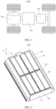
- FIG. 1 is a schematic structural diagram of a vehicle 10000 according to some embodiments of this application.
- the vehicle 10000 may be a fossil fuel vehicle, a natural-gas vehicle, or a new energy vehicle, where the new energy vehicle may be a battery electric vehicle, a hybrid electric vehicle, a range-extended vehicle, or the like.
- the vehicle 10000 is provided with a battery pack 1000 inside, where the battery pack 1000 may be disposed at the bottom, front or rear of the vehicle 10000.
- the battery pack 1000 may be configured to supply power to the vehicle 10000.
- the battery pack 1000 may be used as an operational power source for the vehicle 10000.
- the vehicle 10000 may further include a controller 2000 and a motor 3000, where the controller 2000 is configured to control the battery pack 1000 to supply power to the motor 3000, for example, to satisfy power needs of start, navigation, and driving of the vehicle 10000.
- the battery pack 1000 can be used as not only the operational power source for the vehicle 10000 but also a driving power source for the vehicle 10000, replacing or partially replacing fossil fuel or natural gas to provide driving traction for the vehicle 10000.
- FIG. 2 is a schematic structural diagram of a battery pack 1000 according to some embodiments of this application
- FIG. 3 is a schematic structural diagram of a battery cell 202 according to some embodiments of this application.
- the battery pack 1000 is a packaging unit of a battery module 200, and the battery pack 1000 has complete functions and can be directly used as a power source to provide electrical energy.
- the battery pack 1000 includes a battery pack box 100 and the battery module 200, and the battery module 200 is accommodated in battery pack box 100.
- the battery pack box 100 is configured to provide an accommodating space for the battery module 200.
- the battery pack box 100 may be a variety of structures. In some embodiments, the battery pack box 100 may include a first portion and a second portion.
- the first portion and the second portion fit together to jointly define an accommodating space for accommodating the battery module 200.
- the second portion may be a hollow structure with one end open, and the first portion may be a plate structure, where the first portion covers the open side of the second portion so that the first portion and the second portion jointly define the accommodating space.
- the first portion and the second portion may both be hollow structures with one side open, where the open side of the first portion is engaged with the open side of the second portion.
- the battery cell 202 may be provided in plurality, and the plurality of battery cells 202 may be connected in series, parallel, or series-parallel, where being connected in series-parallel means a combination of series and parallel connections of the plurality of battery cells 202.
- the battery pack 1000 may be formed by connecting the plurality of battery cells 202 in series, parallel, or series-parallel to form a battery module 200 first, and then a plurality of battery modules 200 are connected in series, parallel, or series-parallel to form an entirety which is accommodated in the battery pack box 100.
- the battery pack 1000 may further include other structures.
- the battery pack 1000 may further include a busbar configured to implement electrical connection between the plurality of battery cells 202.
- Each battery cell 202 may be a secondary battery or a primary battery, and may be a lithium-sulfur battery, a sodium-ion battery, or a magnesium-ion battery, without being limited thereto.
- the battery cell 202 may be cylindrical, flat, cuboid, or of other shapes.
- the battery cell 202 refers to a smallest unit constituting a battery. As shown in FIG. 3 , the battery cell 202 includes a battery top cover 202a, a battery housing 202c, a battery bottom wall 202b, a battery assembly 203, and other functional components.
- the battery top cover 202a refers to a component that covers an opening of the battery housing 202c to isolate an internal environment of the battery cell 202 from an external environment.
- the shape of the battery top cover 202a can be adapted to the shape of the battery housing 202c to fit with the battery housing 202c.
- the battery top cover 202a may be made of a material with specified hardness and strength (for example, aluminum alloy), so that the battery top cover 202a is less likely to deform when subjected to squeeze and collision, allowing the battery cell 202 to have higher structural strength and enhanced safety performance.
- the battery top cover 202a may be provided with functional components such as an electrode terminal 202d.
- the electrode terminal 202d may be configured to be electrically connected to the battery assembly 203 for outputting or inputting electrical energy of the battery cell 202.
- the battery top cover 202a may further be provided with a pressure relief mechanism for releasing internal pressure when the internal pressure or temperature of the battery cell 202 reaches a threshold.
- the battery top cover 202a may also be made of various materials, such as copper, iron, aluminum, stainless steel, and aluminum alloy.
- an insulator may also be provided at an inner side of the battery top cover 202a. The insulator may be configured to isolate an electrically connected component in the battery housing 202c from the battery top cover 202a, so as to reduce a risk of short circuits.
- the insulator may be made of plastic, rubber, or the like.
- the battery housing 202c is an assembly configured to fit with the battery top cover 202a to form an internal environment of the battery cell 202, where the formed internal environment may be used for accommodating the battery assembly 203, an electrolyte, and other components.
- the battery housing 202c and the battery top cover 202a may be independent components, an opening may be provided in the battery housing 202c, and the battery top cover 202a is made to cover the opening to form the internal environment of the battery cell 202.
- the battery top cover 202a is welded to the battery housing 202c for closing.
- the battery housing 202c may be of various shapes and sizes, such as a cuboid shape, a cylindrical shape, and a hexagonal prism shape. Specifically, the shape of the battery housing 202c may be determined according to a specific shape and size of the battery assembly 203.
- the battery housing 202c may be made of various materials, such as copper, iron, aluminum, stainless steel, and aluminum alloy.
- the battery assembly 203 is a component in the battery cell 202 in which electrochemical reactions take place.
- the battery housing 202c may include one or more battery assemblies 203.
- the battery assembly 203 is mainly formed by winding or stacking a positive electrode plate and a negative electrode plate, and a separator is generally provided between the positive electrode plate and the negative electrode plate.
- Parts of the positive electrode plate and the negative electrode plate with active substances constitute a body portion of the battery assembly, while parts of the positive electrode plate and the negative electrode plate without active substances constitute tabs 203a respectively.
- a positive tab and a negative tab may both be located at one end of the body portion or be located at two ends of the body portion respectively.
- a positive electrode active substance and a negative electrode active substance react with an electrolyte, and the tabs 203a are connected to the electrode terminals 202d to form a current loop.
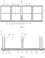
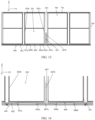
- the battery pack 1000 includes a battery pack lower box 101, a battery module 200, and a pressure regulating member 300 in a wedge shape.
- the battery pack lower box 101 has a box bottom wall 102.
- the battery module 200 has a module bottom wall 201a.
- the box bottom wall 102 has a module opposition region 102a, where the module opposition region 102a has a transverse direction and is disposed opposite the module bottom wall 201a, and the transverse direction is consistent with a height direction of battery cells 202 of the battery module 200.
- the pressure regulating member 300 is disposed in module opposition region 102a.
- the pressure regulating member 300 has a first side 300a and a second side 300b in the transverse direction.
- the first side 300a is closer to a battery top cover 202a of the battery cell 202 than the second side 300b.
- the second side 300b is closer to a battery bottom wall 202b of the battery cell 202 than the first side 300a.
- the pressure regulating member 300 has a spacing from the module bottom wall 201a, and a spacing from the first side 300a is greater than a spacing from the second side 300b.
- the bottom of the battery pack box 100 in a height direction of the box (that is, direction Z of the coordinate system in the figure) is close to a vehicle floor, and is prone to squeeze and impact.
- the battery pack lower box 101 is a part having the bottom (that is, close to the vehicle floor) in the height direction of the box.
- the battery pack lower box 101 defines the bottom of the accommodating space used for accommodating the battery module 200 to be substantially flat in the height direction of the box.
- the vehicle floor is another entity in a deployment environment of the battery pack 1000.
- the box bottom wall 102 is the bottom of the battery pack lower box 101 in the height direction of the box, close to the vehicle floor.
- the box bottom wall 102 is a thin plate and disposed horizontally (that is, perpendicular to the direction Z of the coordinate system in the figure).
- the battery pack lower box 101 defines the bottom of the accommodating space used for accommodating the battery module 200 to be substantially flat in the height direction of the box.
- the module bottom wall 201a is the bottom of the module housing 201 in the battery module 200 in the height direction of the box.
- the module bottom wall 201a is close to but not in contact with the box bottom wall 102.
- the module bottom wall 201a is disposed horizontally (that is, perpendicular to the direction Z of the coordinate system in the figure), and parallel to the box bottom wall 102.
- the module bottom wall 201a further covers the outside of multiple battery cells 202 and is close to the battery cells 202.
- the height of the battery cell 202 is a maximum height from the battery top cover 202a to the battery bottom wall 202b.
- the IEC 61960 standard is used as an example.
- the height of the battery cell 202 is a maximum height N4 of battery cell specified in the IEC 61960 standard
- thickness of the battery cell 202 is a maximum thickness N2 of battery cell specified in the IEC 61960 standard
- width of the battery cell 202 is a maximum width N3 of battery cell specified in the IEC 61960 standard.
- the battery cell 202 is laterally disposed in the battery module 200.
- the height direction of the battery cell 202 is a direction Y of the coordinate system in the figure
- the thickness direction of the battery cell 202 is a direction X of the coordinate system in the figure
- the width direction of the battery cell 202 is the direction Z of the coordinate system in the figure.
- the battery bottom wall 202b is perpendicular to the direction Y of the coordinate system in the figure
- two thickness surfaces of the battery housing 202c are perpendicular to the direction Z of the coordinate system in the figure, where one thickness surface is covered by the module bottom wall 201a.
- the module opposition region 102a is a region obtained by projecting the module bottom wall 201a towards the box bottom wall 102 in the direction Z of the coordinate system, and located on the box bottom wall 102 and facing towards the module bottom wall 201a.
- the transverse direction of the module opposition region 102a is consistent with the height direction of the battery cell 202, that is, the direction Y of the coordinate system.
- the pressure regulating member 300 is disposed on the module opposition region 102a of the box bottom wall 102, located between the box bottom wall 102 and the module bottom wall 201a, and configured to adjust the force transmission manner of a squeezing force transmitted from the box bottom wall 102 to the module bottom wall 201a.
- the bottom surface of the pressure regulating member 300 in the height direction of the box sticks close to the box bottom wall 102, and the top surface in the height direction of the box faces towards the module bottom wall 201a, being close to but not in contact with the module bottom wall 201a.
- the spacing is the distance from the top surface of the pressure regulating member 300 in the height direction of the box to the module bottom wall 201a.
- a cross section of the pressure regulating member 300 perpendicular to the direction X extends upwards in the direction Y, and has a first side 300a and a second side 300b.
- one side close to the battery top cover 202a is the first side 300a
- the other side close to the battery bottom wall 202b is the second side 300b.
- the distance from the top surface of the pressure regulating member 300 to the module bottom wall 201a is larger at the first side 300a, and the distance from the top surface of the pressure regulating member 300 to the module bottom wall 201a is smaller at the second side 300b.
- the distance from the top surface of the pressure regulating member 300 to the module bottom wall 201a is larger at the first side 300a, and the distance from the top surface of the pressure regulating member 300 to the module bottom wall 201a at the second side 300b, which is achieved by making the height of the first side 300a of the pressure regulating member 300 smaller than the height of the second side 300b in the height direction of the box (the direction Z of the coordinate system).
- the wedge shape of the pressure regulating member 300 means that the cross section of the pressure regulating member 300 perpendicular to the direction X exhibits a trend of being low on one side and high on the other side in the direction Y. Shapes having this trend can all be understood as the wedge shape herein.
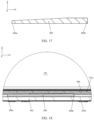
- the cross section of the pressure regulating member 300 perpendicular to the direction X is a right trapezoid, indicating that a hypotenuse of the right trapezoid of the top surface of the pressure regulating member 300 exhibits a trend of being low on one side and high on the other side in the direction Y, which is within the scope of the meaning of the wedge shape.
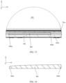
- the cross section of the pressure regulating member 300 perpendicular to the direction X is as shown in FIG. 8 , indicating that a continuous curve of the top surface exhibits a trend of being low on one side and high on the other side in the direction Y, which is within the scope of the meaning of the wedge shape.
- a change rate of the curve gradually decreases to 0 from the first side 300a to the second side 300b.
- the continuous curve indicates that the top surface of the pressure regulating member 300 is a curved surface.
- the cross section of the pressure regulating member 300 perpendicular to the direction X is as shown in FIG.
- the continuous broken line segment includes a horizontal line segment and an inclined line segment connected to the horizontal line segment.
- the inclined line segment shows an upward trend until it is connected to the horizontal line segment.
- the continuous broken line segment indicates that the top surface of the pressure regulating member 300 includes an upward inclined surface and a horizontal surface connected to the inclined surface and parallel to the module bottom wall 201a.
- the pressure regulating member 300 is an entity obtained by extending the cross section perpendicular to the direction X in the module opposition region 102a along the direction X. Close fitting between the module bottom wall 201a and the box bottom wall 102 limits the direction-Z size of the pressure regulating member 300 to be relatively small, and the direction-X size and direction-Y size of the pressure regulating member 300 to be relatively large, so that the overall pressure regulating member 300 takes a form of flat gasket.
- the pressure regulating member 300 is made of polyhexamethylene adipamide (PA66). In other embodiments, the pressure regulating member 300 is made of other hard materials.
- PA66 polyhexamethylene adipamide
- the pressure regulating member 300 is integrated with the box bottom wall 102 to form an integral structure so as to achieve mechanical connection therebetween.
- the material of the pressure regulating member 300 is the same as the material of box bottom wall 102.
- the spacing between the first side 300a of the pressure regulating member 300 close to the battery top cover 202a and the module bottom wall 201a is large, and the spacing between the second side 300b of the pressure regulating member 300 close to the battery bottom wall 202b and the module bottom wall 201a is small.
- the box bottom wall 102 is squeezed and deformed to intrude into the accommodating space for accommodating the battery module 200, leading to a positive movement in the direction Z, and further leading to a positive movement of the pressure regulating member 300 in the direction Z.
- Coming into contact with and squeezing the module bottom wall 201a specifically means coming into contact with the top surface of the pressure regulating member 300 and squeezing the module bottom wall 201a.
- the first side 300a of the pressure regulating member 300 with the largest spacing finally comes into contact with a position on the module bottom wall 201a close to the battery top cover 202a.
- the top surface of the pressure regulating member 300 fully comes into contact with the module bottom wall 201a.
- the module bottom wall 201a transmits the squeezing force to the battery cell 202 through a thickness surface of the battery housing 202c in the battery cell 202 covered by the module bottom wall 201a.
- the module bottom wall 201a first transmits a larger squeezing force to the position on the battery housing 202c far from the battery top cover 202a and close to the battery bottom wall 202b, and then transmits a smaller squeezing force to the position on the battery housing 202c close to the battery top cover 202a, thereby protecting the welded region between the battery top cover 202a and the battery housing 202c under a squeezing condition.
- the battery pack lower box 101 further includes a reinforcer 107 and a load-bearing wall 105 for bearing the battery module 200.
- the reinforcer 107 is disposed between two module opposition regions 102a and connected to the load-bearing wall 105, and supports the box bottom wall 102.
- the load-bearing wall 105 is a plate in the battery pack lower box 101 for bearing the battery module 200, including two first box side plates 103 at two ends of the battery pack lower box 101 in the direction X and a partition 106 disposed in the accommodating space of the battery pack lower box 101.
- the two first box side plates 103 and partition 106 are both disposed parallel to the direction Y of the coordinate system.
- the two ends of the first box side plates 103 and partition 106 in the direction Y are respectively connected to two second box side plates 104, and the bottoms of the first box side plates 103 and partition 106 are both connected to the box bottom wall 102.
- the partition 106 is disposed at a middle position between the two first box side plates 103, dividing the accommodating space of the battery pack lower box 101 into two secondary accommodating spaces.
- the direction-X size of each secondary accommodating space is adapted to the direction-X size of one battery module 200.
- Each secondary accommodating space accommodates one battery module 200 in the direction X.
- the two ends in the direction X of the module housing 201 of the battery module 200 are respectively supported and fixed by the first box side plate 103 and partition 106, so that the module bottom wall 201a is close to but not in contact with the box bottom wall 102.
- each secondary accommodating space is adapted to the direction-Y size of at least two battery modules 200.
- Each secondary accommodating space accommodates at least two battery modules 200 in the direction Y.
- the at least two module opposition regions 102a are present in the direction Y of the box bottom wall 102.
- each secondary accommodating space accommodates four battery modules 200 in the direction Y.
- each secondary accommodating space accommodates another quantity of battery modules 200 in the direction Y, and the another quantity is at least two.
- the reinforcer 107 is a component for transmitting the squeezing force borne by the box bottom wall 102 to the load-bearing wall 105.
- the reinforcer 107 is disposed in the accommodating space of the battery pack lower box 101. Specifically, the direction-Z bottom surface of the reinforcer 107 sticks close to a region between the two module opposition regions 102a on the box bottom wall 102, and extends along the direction X to connect to the first box side plate 103 and the partition 106, so that the squeezing force borne by the box bottom wall 102 under a squeezing condition is transmitted to the first box side plate 103 and the partition 106 through the reinforcer 107.
- the region between the two module opposition regions 102a is prone to large deformation when squeezed. Therefore, the reinforcer 107 is disposed in the region to connect to the load-bearing wall 105 so as to support the box bottom wall 102, improving the capability of the box bottom wall 102 to resist squeezing and deformation.
- the squeezing force applied to the box bottom wall 102 is transmitted to the first box side plate 103 and the partition 106 via the reinforcer 107.
- the first box side plate 103, the partition 106, and the reinforcer 107 jointly assist the box bottom wall 102 in resisting a positive movement in the direction Z caused by squeezing and deformation, reducing the displacement of the box bottom wall 102 intruding into the accommodating space of the battery pack lower box 101, thereby protecting structures such as the battery module 200 in the accommodating space of the battery pack lower box 101.
- the reinforcer 107 includes a platform part 107a and a ridge part 107b.
- the platform part 107a sticks close to the box bottom wall 102, and the ridge part 107b protrudes from the platform part 107a into the battery pack lower box 101 and is connected to the load-bearing wall 105.
- the platform part 107a and the ridge part 107b are both strip-shaped plates.
- the direction-Z bottom surface of the platform part 107a sticks close to the region between the two module opposition regions 102a on the box bottom wall 102.
- the ridge part 107b protrudes from the direction-Z top surface of the platform part 107a along the direction Z into the accommodating space of the battery pack lower box 101, so that the reinforcer 107 has a T-shaped cross section perpendicular to the direction X.
- An entity obtained by extending the T-shaped cross section along the direction X is the reinforcer 107.
- the protruding ridge part 107b is connected to the load-bearing wall 105. Specifically, a junction of the ridge part 107b and the first box side plate 103 and a junction of the ridge part 107b and the partition 106 are both welded for sufficient force transmission.
- the direction-Z top of ridge part 107b is roughly at the same direction-Z height as the direction-Z middle position of the battery module 200.
- the ridge part 107b and the first box side plate 103 and partition 106 are connected in other manners.
- the platform part 107a is configured to strengthen the connection between the reinforcer 107 and the box bottom wall 102.
- the connection relationship and connection manner between the platform part 107a and the load-bearing wall 105 are not limited herein.
- the reinforcer 107 sticks close to the box bottom wall 102 through the direction-Z bottom surface of the platform part 107a, achieving a large-area surface contact between the reinforcer 107 and the box bottom wall 102, and increasing the contact area between the reinforcer 107 and the box bottom wall 102.
- the load-bearing wall 105 and the reinforcer 107 have a good effect in preventing the box bottom wall 102 from intruding into the accommodating space of the battery pack lower box 101 under squeezing and deformation.
- the reinforcer 107 is disposed between first sides 300a of two pressure regulating members 300 facing towards each other.
- the transverse direction that is, the direction Y of the coordinate system
- the arrangement direction of the battery cells 202 in the battery module 200 affects disposition of the reinforcer 107 in the region between the two module opposition regions 102a.
- the welded region between the battery housing 202c and the battery top cover 202a has a high priority of protection
- a region of the battery housing 202c close to the battery bottom wall 202b has a low priority of protection.
- the reinforcer 107 cannot be disposed in some of the regions between the two module opposition regions 102a. In this case, the disposition of the reinforcer 107 on the regions between the two module opposition regions 102a should give priority to protecting the welded region between the battery housing 202c and the battery top cover 202a.
- the arrangement direction of the battery cells 202 in four battery modules 200 is as follows: regions between module opposition regions 102a at two ends in the direction Y are close to the battery bottom wall 202b on their both sides; a region between module opposition regions 102a at the middle position in the direction Y is close to the battery top cover 202a on its both sides; the priority of disposing the reinforcer 107 on the two regions at the two ends in the direction Y is low; and the priority of disposing the reinforcer 107 on a region at the middle position in the direction Y is high. Therefore, the reinforcer 107 on the region at the middle position in the direction Y. That is, the reinforcer 107 is disposed between the first sides 300a of the two pressure regulating members 300 facing towards each other.
- the region between the two module opposition regions 102a between the first sides 300a of the two pressure regulating members 300 facing towards each other is closer to a position of the module bottom wall 201a close to the battery top cover 202a. If the box bottom wall 102 is squeezed and deformed at that region, the welded region between the battery top cover 202a and a battery housing 202c with a low bearing capacity is prone to squeeze. Therefore, the reinforcer 107 is disposed between the first sides 300a of the two pressure regulating members 300 facing towards each other to prevent the box bottom wall 102 from intruding into that region under deformation, so as to protect the welded region between the battery top cover 202a and a battery housing 202c.
- the box bottom wall 102 further has a longitudinal direction perpendicular to the transverse direction, and the reinforcer 107 is disposed on a center line in the longitudinal direction.
- the longitudinal direction is the direction X of the coordinate system
- the center line in the longitudinal direction is a line parallel to the direction X and at the middle position in the direction Y of the box bottom wall 102.
- the reinforcer 107 extends on the center line along the direction X.
- the box bottom wall 102 has its two edges in the direction Y respectively connected to the two second box side plates 104, having a weak capability to resist squeezing and deformation at the middle position in the direction Y. Therefore, the box bottom wall 102 is prone to large intrusion when squeezed and deformed at the middle position in the direction Y, damaging structures such as the battery module 200 in the accommodating space of the battery pack lower box 101.
- the center line in the longitudinal direction is located at the middle position in the direction Y.
- the reinforcer 107 being disposed on the center line of the longitudinal direction of the region between the module opposition regions 102a improves the capability of the box bottom wall 102 to resist squeezing and deformation at the middle position in the direction Y, thereby protecting structures such as the battery module 200.
- the box bottom wall 102 further has a longitudinal direction perpendicular to the transverse direction, and pressure regulating members 300 are disposed on two sides of the center line in the longitudinal direction respectively.
- the longitudinal direction is the direction X of the coordinate system
- the center line in the longitudinal direction is a line parallel to the direction X and at the middle position in the direction Y of the box bottom wall 102.
- Pressure regulating members 300 are disposed on two sides of the direction Y of the center line.
- the box bottom wall 102 has its two edges in the direction Y respectively connected to the two second box side plates 104, having a weak capability to resist squeezing and deformation at the middle position in the direction Y. Therefore, the box bottom wall 102 is prone to large intrusion when squeezed and deformed at the middle position in the direction Y, damaging structures such as the battery module 200 in the accommodating space of the battery pack lower box 101. Therefore, the pressure regulating members 300 are disposed at the module opposition regions 102a on the two sides of the middle position in the direction Y.
- the center line in the longitudinal direction is located at the middle position in the direction Y.
- the pressure regulating members 300 are disposed on two sides of the direction Y of the center line of the longitudinal direction, that is, the pressure regulating members 300 are disposed on two sides of the middle position of the direction Y of the box bottom wall 102.
- the pressure regulating members 300 are disposed on two module opposition regions 102a on two sides of the middle position in the direction Y. However, no pressure regulating member 300 is disposed on two module opposition regions 102a at two ends in the direction Y, because the two module opposition regions 102a are adjacent to the second box side plate 104. Therefore, the box bottom wall 102 has a good capability to resist squeezing and deformation at the two module opposition regions 102a, thereby well protecting structures such as a corresponding battery module 200. In other embodiments, the pressure regulating members 300 may alternatively be disposed on the two module opposition regions 102a.
- the battery pack 1000 further includes a cushion member 400.
- the cushion member 400 is disposed between the pressure regulating member 300 and the module bottom wall 201a.
- the cushion member 400 is specifically a cushion pad.
- the direction-Z top surface of the cushion pad is adhered to the module bottom wall 201a by using an adhesive, and the direction-Z bottom surface of the cushion pad faces towards the top surface of the pressure regulating member 300, being close to but not in contact with the top surface of the pressure regulating member 300.
- the cushion member 400 reduces an impact force transmitted from the pressure regulating member 300 to the module bottom wall 201a, and thus reduces an impact force transmitted from the module bottom wall 201a to the battery cell 202, protecting the battery module 200 and the battery cell 202.
- this application provides a battery pack 1000.
- the battery pack 1000 includes a battery pack lower box 101, a battery module 200, and a pressure regulating member 300 in a wedge shape.
- the battery module 200 has a module bottom wall 201a.
- the battery pack lower box 101 has a box bottom wall 102.
- the box bottom wall 102 has a module opposition region 102a, where the module opposition region 102a has a transverse direction and is disposed opposite the module bottom wall 201a, and the transverse direction is consistent with a height direction of battery cells 202 of the battery module 200, namely, direction Y of the coordinate system.
- the pressure regulating member 300 is disposed in the module opposition region 102a, with its bottom surface fitting the box bottom wall 102.
- the pressure regulating member 300 has a spacing with the module bottom wall 201a and has a top surface facing the module bottom wall 201a and being close to but not in contact with the module bottom wall 201a.
- the overall pressure regulating member 300 takes a form of a flat subplate, and has a right trapezoid cross section perpendicular to the direction X. An entity obtained by extending the right trapezoid cross section in the module opposition region 102a along the direction X is the pressure regulating member 300.
- a hypotenuse of the right trapezoid of the top surface of the pressure regulating member 300 exhibits a trend of being low on one side and high on the other side in the direction Y.
- the low side closer to the battery top cover 202a of the battery cell 202 is the first side 300a
- the high side closer to the battery bottom wall 202b of the battery cell 202 is the second side 300b.
- a spacing between the first side 300a and the module bottom wall 201a is larger than a spacing between the second side 300b and the module bottom wall 201a.
- the battery pack lower box 101 further includes a reinforcer 107 and a load-bearing wall 105 for bearing the battery module 200.
- the load-bearing wall 105 is a plate in the battery pack lower box 101 for bearing the battery module 200, including two first box side plates 103 at two ends of the battery pack lower box 101 in the direction X and a partition 106 disposed in the accommodating space of the battery pack lower box 101.
- the two first box side plates 103 and partition 106 are both disposed parallel to the direction Y of the coordinate system.
- the two ends of the first box side plates 103 and partition 106 in the direction Y are respectively connected to two second box side plates 104, and the bottoms of the first box side plates 103 and partition 106 are both connected to the box bottom wall 102.
- the partition 106 is disposed at a middle position between the two first box side plates 103, dividing the accommodating space of the battery pack lower box 101 into two secondary accommodating spaces.
- the direction-X size of each secondary accommodating space is adapted to the direction-X size of one battery module 200.
- Each secondary accommodating space accommodates one battery module 200 in the direction X.
- the two ends in the direction X of the module housing 201 of the battery module 200 are respectively supported and fixed by the first box side plate 103 and partition 106.
- Each secondary accommodating space accommodates four battery modules 200 in the direction Y.
- Pressure regulating members 300 are disposed at the two module opposition regions 102a on the two sides of the middle position in the direction Y.
- the two pressure regulating members 300 are located on two sides of the center line in the longitudinal direction of the box bottom wall 102, while no pressure regulating member 300 is disposed at the two module opposition regions 102a at the two ends in the direction Y.
- the reinforcer 107 is disposed in the region between the two module opposition regions 102a at the middle position in the direction Y, specifically extends on the center line of the longitudinal direction along the direction X, and is located between the first sides 300a of the two pressure regulating members 300 facing towards each other.
- the reinforcer 107 includes a platform part 107a and a ridge part 107b.
- the platform part 107a and the ridge part 107b are both strip-shaped plates.
- the bottom surface of the platform part 107a sticks close to the box bottom wall 102.
- the ridge part 107b protrudes from the top surface of the platform part 107a along the direction Z into the accommodating space of the battery pack lower box 101, so that the reinforcer 107 has a T-shaped cross section perpendicular to the direction X.
- An entity obtained by extending the T-shaped cross section along the direction X to connect to the first box side plate 103 and the partition 106 is the reinforcer 107.
- a junction of the ridge part 107b and the first box side plate 103 and a junction of the ridge part 107b and the partition 106 are both welded.
- the direction-Z top of ridge part 107b is roughly at the same direction-Z height as the direction-Z middle position of the battery module 200.
- the platform part 107a is configured to strengthen the connection between the reinforcer 107 and the box bottom wall 102.
- the connection relationship and connection manner between the platform part 107a and the load-bearing wall 105 are not limited herein.
- the battery pack lower box 601 includes a box bottom wall 602 and a pressure regulating member 800 in a wedge shape.
- the box bottom wall 602 has a module opposition region 602a, where the module opposition region 602a has a transverse direction and is disposed opposite the module bottom wall 701a of the battery module 700, and the transverse direction is consistent with a height direction of battery cells 202 of the battery module 700.
- the pressure regulating member 800 is disposed in the module opposition region 602a.
- the pressure regulating member 800 has a first side 800a and a second side 800b in the transverse direction.
- the first side 800a is closer to a battery top cover 202a of the battery cell 202 than the second side 800b.
- the second side 800b is closer to a battery bottom wall 202b of the battery cell 202 than the first side 800a.
- the height of the first side 800a is lower than the height of the second side 800b.
- the bottom of the battery pack box 600 in a height direction of the box (that is, direction Z of the coordinate system in the figure) is close to a vehicle floor, and is prone to squeeze and impact.
- the battery pack lower box 601 is a part having the bottom (that is, close to the vehicle floor) in the height direction of the box.
- the battery pack lower box 601 defines the bottom of the accommodating space used for accommodating the battery module 700 to be substantially flat in the height direction of the box.
- the vehicle floor is another entity in a deployment environment of the battery pack 1000.
- the box bottom wall 602 is the bottom of the battery pack lower box 601 in the height direction of the box, close to the vehicle floor.
- the box bottom wall 602 is a thin plate and disposed horizontally (that is, perpendicular to the direction Z of the coordinate system in the figure).
- the battery pack lower box 601 defines the bottom of the accommodating space used for accommodating the battery module 700 to be substantially flat in the height direction of the box.
- the module bottom wall 701a is the bottom of the module housing 701 in the battery module 700 in the height direction of the box.
- the module bottom wall 701a is close to but not in contact with the box bottom wall 602.
- the module bottom wall 701a is disposed horizontally (that is, perpendicular to the direction Z of the coordinate system in the figure) and parallel to the box bottom wall 602.
- the module bottom wall 701a further covers the outside of multiple battery cells 202 and is close to the battery cells 202.
- the height of the battery cell 202 is a maximum height from the battery top cover 202a to the battery bottom wall 202b.
- the IEC 61960 standard is used as an example.
- the height of the battery cell 202 is a maximum height N4 of battery cell specified in the IEC 61960 standard
- thickness of the battery cell 202 is a maximum thickness N2 of battery cell specified in the IEC 61960 standard
- width of the battery cell 202 is a maximum width N3 of battery cell specified in the IEC 61960 standard.
- the battery cell 202 is laterally disposed in the battery module 700.
- the height direction of the battery cell 202 is a direction Y of the coordinate system in the figure
- the thickness direction of the battery cell 202 is a direction X of the coordinate system in the figure
- the width direction of the battery cell 202 is the direction Z of the coordinate system in the figure.
- the battery bottom wall 202b is perpendicular to the direction Y of the coordinate system in the figure
- two thickness surfaces of the battery housing 202c are perpendicular to the direction Z of the coordinate system in the figure, where one thickness surface is covered by the module bottom wall 701a.
- the module opposition region 602a is a region obtained by projecting the module bottom wall 701a towards the box bottom wall 602 in the direction Z of the coordinate system when the battery module 700 is packaged into the battery pack lower box 601.
- the module opposition region 602a is located on the box bottom wall 602 and faces towards the module bottom wall 701a.
- the transverse direction of the module opposition region 602a is consistent with the height direction of the battery cell 202, that is, the direction Y of the coordinate system.
- the pressure regulating member 800 is disposed on the module opposition region 602a of the box bottom wall 602.
- the pressure regulating member 800 is located between the box bottom wall 602 and the module bottom wall 701a, and configured to adjust the force transmission manner of a squeezing force transmitted from the box bottom wall 602 to the module bottom wall 701a.
- the bottom surface of the pressure regulating member 800 in the height direction of the box fits the box bottom wall 602, and the top surface in the height direction of the box faces towards the module bottom wall 701a, being close to but not in contact with the module bottom wall 701a.
- the spacing is the distance from the top surface of the pressure regulating member 800 in the height direction of the box to the module bottom wall 701a.
- a cross section of the pressure regulating member 800 perpendicular to the direction X extends upwards in the direction Y, and the pressure regulating member 800 has a first side 800a and a second side 800b. In the two sides, one side close to the battery top cover 202a is the first side 800a, and the other side close to the battery bottom wall 202b is the second side 800b.
- the height of the first side 800a of the pressure regulating member 800 is higher than the height of the second side 800b.
- the distance from the top surface of the pressure regulating member 800 to the module bottom wall 701a is larger at the first side 800a, and the distance from the top surface of the pressure regulating member 800 to the module bottom wall 701a is smaller at the second side 800b.
- the distance from the top surface of the pressure regulating member 800 to the module bottom wall 701a at the first side 800a is larger than the distance from the top surface of the pressure regulating member 800 to the module bottom wall 701a at the second side 800b.
- the wedge shape of the pressure regulating member 800 means that the cross section of the pressure regulating member 800 perpendicular to the direction X exhibits a trend of being low on one side and high on the other side in the direction Y. Shapes having this trend can all be understood as the wedge shape herein.
- the cross section of the pressure regulating member 800 perpendicular to the direction X is a right trapezoid, indicating that a hypotenuse of the right trapezoid of the top surface of the pressure regulating member 800 exhibits a trend of being low on one side and high on the other side in the direction Y, which is within the scope of the meaning of the wedge shape.
- the cross section of the pressure regulating member 800 perpendicular to the direction X is as shown in FIG. 16 , indicating that a continuous curve of the top surface exhibits a trend of being low on one side and high on the other side in the direction Y, which is within the scope of the meaning of the wedge shape.
- a change rate of the curve gradually decreases to 0 from the first side 800a to the second side 800b.
- the continuous curve indicates that the top surface of the pressure regulating member 800 is a curved surface.
- the cross section of the pressure regulating member 800 perpendicular to the direction X is as shown in FIG.
- the continuous broken line segment includes a horizontal line segment and an inclined line segment connected to the horizontal line segment.
- the inclined line segment shows an upward trend until it is connected to the horizontal line segment.
- the horizontal line segment is parallel to the module bottom wall 701a.
- the continuous broken line segment indicates that the top surface of the pressure regulating member 800 includes an upward inclined surface and a horizontal surface connected to the inclined surface and parallel to the module bottom wall 701a.
- the pressure regulating member 800 is an entity obtained by extending the cross section perpendicular to the direction X in the module opposition region 602a along the direction X.
- the pressure regulating member 800 limits the direction-Z size of the pressure regulating member 800 to be relatively small, and the direction-X size and direction-Y size of the pressure regulating member 800 to be relatively large, so that the overall pressure regulating member 800 takes a form of flat subplate.
- the pressure regulating member 800 is made of polyhexamethylene adipamide (PA66). In other embodiments, the pressure regulating member 800 is made of other hard materials.
- PA66 polyhexamethylene adipamide
- the pressure regulating member 800 is integrated with the box bottom wall 602 to form an integral structure so as to achieve mechanical connection between the two.
- the material of the pressure regulating member 800 is consistent with the material of box bottom wall 602.
- the spacing between the first side 800a of the pressure regulating member 800 close to the battery top cover 202a and the module bottom wall 701a is large, and the spacing between the second side 800b of the pressure regulating member 800 close to the battery bottom wall 202b and the module bottom wall 701a is small.
- the box bottom wall 602 is squeezed and deformed to intrude into the accommodating space for accommodating the battery module 700, leading to a positive movement in the direction Z, and further leading to a positive movement of the pressure regulating member 800 in the direction Z.
- Coming into contact with and squeezing the module bottom wall 701a specifically means coming into contact with the top surface of the pressure regulating member 800 and squeezing the module bottom wall 701a. Since the distances from various positions of the top surface of the pressure regulating member 800 to the module bottom wall 701a in the direction Y are inconsistent, a position with a small spacing on the top surface of the pressure regulating member 800 comes into contact with and squeezes the module bottom wall 701a first, and a position with a large spacing comes into contact with and squeezes the module bottom wall 701a later. Specifically, the second side 800b of the pressure regulating member 800 with the smallest spacing first comes into contact with a position of the module bottom wall 701a close to the battery bottom wall 202b.
- the top surface of the pressure regulating member 800 starts to partially come into contact with the module bottom wall 701a.
- the first side 800a of the pressure regulating member 800 with the largest spacing finally comes into contact with a position of the module bottom wall 701a close to the battery top cover 202a.
- the top surface of the pressure regulating member 800 fully comes into contact with the module bottom wall 701a. This makes the position of the module bottom wall 701a close to the battery bottom wall 202b first bear a larger squeezing force, and the position of the module bottom wall 701a close to the battery top cover 202a then bear a smaller squeezing force.
- the module bottom wall 701a transmits the squeezing force to the battery cell 202 through a thickness surface of the battery housing 202c in the battery cell 202 covered by the module bottom wall 701a.
- the module bottom wall 701a first transmits a larger squeezing force to the position on the battery housing 202c far from the battery top cover 202a and close to the battery bottom wall 202b, and then transmits a smaller squeezing force to the position on the battery housing 202c close to the battery top cover 202a, thereby protecting the welded region between the battery top cover 202a and the battery housing 202c under a squeezing condition.
- the battery pack lower box 601 further includes a reinforcer 607 and a load-bearing wall 605 for bearing the battery module 700.
- the reinforcer 607 is disposed between two module opposition regions 602a and connected to the load-bearing wall 605, and supports the box bottom wall 602.
- the load-bearing wall 605 is a plate in the battery pack lower box 601 for bearing the battery module 700, including two first box side plates 603 at two ends of the battery pack lower box 601 in the direction X and a partition 606 disposed in the accommodating space of the battery pack lower box 601.
- the two first box side plates 603 and partition 606 are both disposed parallel to the direction Y of the coordinate system.
- the two ends of the first box side plates 603 and partition 606 in the direction Y are respectively connected to two second box side plates 604, and the bottoms of the first box side plates 603 and partition 606 are both connected to the box bottom wall 602.
- the partition 606 is disposed at a middle position between the two first box side plates 603, dividing the accommodating space of the battery pack lower box 601 into two secondary accommodating spaces.
- the direction-X size of each secondary accommodating space is adapted to the direction-X size of one battery module 700.
- Each secondary accommodating space is used for accommodating one battery module 700 in the direction X.
- each secondary accommodating space is adapted to the direction-Y size of at least two battery modules 700.
- Each secondary accommodating space is used for accommodating at least two battery modules 700 in the direction Y.
- the at least two module opposition regions 602a are present in the direction Y of the box bottom wall 602.
- each secondary accommodating space is used for accommodating four battery modules 700 in the direction Y.
- each secondary accommodating space is used for accommodating another quantity of battery modules 700 in the direction Y, and the another quantity is at least two.
- the reinforcer 607 is a component for transmitting the squeezing force borne by the box bottom wall 602 to the load-bearing wall 605.
- the reinforcer 607 is disposed in the accommodating space of the battery pack lower box 601. Specifically, the direction-Z bottom surface of the reinforcer 607 sticks close to the region between the two module opposition regions 602a on the box bottom wall 602, and extends along the direction X to connect to first box side plate 603 and the partition 606, so that the squeezing force borne by the box bottom wall 602 under a squeezing condition is transmitted to the first box side plate 603 and the partition 606 through the reinforcer 607.
- the reinforcer 607 is disposed in the region to connect to the load-bearing wall 605 so as to support the box bottom wall 602, improving the capability of the box bottom wall 602 to resist squeezing and deformation.
- the first box side plate 603, the partition 606, and the reinforcer 607 jointly assist the box bottom wall 602 in resisting a positive movement in the direction Z caused by squeezing and deformation, reducing the displacement of the box bottom wall 602 intruding into the accommodating space of the battery pack lower box 601.
- structures such as the battery module 700 in the accommodating space of the battery pack lower box 601 are protected.
- the reinforcer 607 includes a platform part 607a and a ridge part 607b.
- the platform part 607a sticks close to the box bottom wall 602, and the ridge part 607b protrudes from the platform part 607a into the battery pack lower box 601 and is connected to the load-bearing wall 605.
- the platform part 607a and the ridge part 607b are both strip-shaped plates.
- the direction-Z bottom surface of the platform part 607a is close to the region between the two module opposition regions 602a on the box bottom wall 602.
- the ridge part 607b protrudes from the direction-Z top surface of the platform part 607a along the direction Z into the accommodating space of the battery pack lower box 601, so that the reinforcer 607 has a T-shaped cross section perpendicular to the direction X.
- An entity obtained by extending the T-shaped cross section along the direction X is the reinforcer 607.
- the protruding ridge part 607b is connected to the load-bearing wall 605. Specifically, a junction of the ridge part 607b and the first box side plate 603 and a junction of the ridge part 607b and the partition 606 are both welded for sufficient force transmission.
- the direction-Z top of ridge part 607b is roughly at the same direction-Z height as the direction-Z middle position of the battery module 700.
- the ridge part 607b and the first box side plate 603 and partition 606 are connected in other manners.
- the platform part 607a is configured to strengthen the connection between the reinforcer 607 and the box bottom wall 602.
- the connection relationship and connection manner between the platform part 607a and the load-bearing wall 605 are not limited herein.
- the reinforcer 607 sticks close to the box bottom wall 602 through the direction-Z bottom surface of the platform part 607a, achieving a large-area surface contact between the reinforcer 607 and the box bottom wall 602, and increasing the contact area between the reinforcer 607 and the box bottom wall 602.
- the load-bearing wall 605 and the reinforcer 607 have a good effect in preventing the box bottom wall 602 from intruding into the accommodating space of the battery pack lower box 601 under squeezing and deformation.
- the reinforcer 607 is disposed between first sides 800a of two pressure regulating members 800 facing towards each other.
- the transverse direction that is, the direction Y of the coordinate system
- the arrangement direction of the battery cells 202 in the battery module 700 affects disposition of the reinforcer 607 in the region between the two module opposition regions 602a.
- the welded region between the battery housing 202c and the battery top cover 202a has a high priority of protection
- the region of the battery housing 202c close to the battery bottom wall 202b has a low priority of protection.
- the reinforcer 607 cannot be disposed in some of the regions between the two module opposition regions 602a. In this case, the disposition of the reinforcer 607 on the regions between the two module opposition regions 602a should give priority to protecting the welded region between the battery housing 202c and the battery top cover 202a.
- the arrangement direction of the battery cells 202 in four battery modules 700 is as follows: regions between the module opposition regions 602a at two ends in the direction Y are close to the battery bottom wall 202b on their both sides; a region between the module opposition regions 602a at the middle position in the direction Y is close to the battery top cover 202a on its both sides; the priority of disposing the reinforcer 607 on the two regions at the two ends in the direction Y is low; and the priority of disposing the reinforcer 607 on the one region at the middle position in the direction Y is high. Therefore, the reinforcer 607 is disposed on the region at the middle position in the direction Y. That is, the reinforcer 607 is disposed between the first sides 800a of the two pressure regulating members 800 facing towards each other.
- the region between the two module opposition regions 602a between the first sides 800a of the two pressure regulating members 800 facing towards each other is closer to a position of the module bottom wall 701a close to the battery top cover 202a. If the box bottom wall 602 is squeezed and deformed at that region, the welded region between the battery top cover 202a and a battery housing 202c with a low bearing capacity is prone to squeeze. Therefore, the reinforcer 607 is disposed between the first sides 800a of the two pressure regulating members 800 facing towards each other to prevent the box bottom wall 602 from intruding into that region under deformation, so as to protect the welded region between the battery top cover 202a and a battery housing 202c.
- the box bottom wall 602 further has a longitudinal direction perpendicular to the transverse direction, and the reinforcer 607 is disposed on a center line in the longitudinal direction.
- the longitudinal direction is the direction X of the coordinate system
- the center line in the longitudinal direction is a line parallel to the direction X and at the middle position in the direction Y of the box bottom wall 602.
- the reinforcer 607 extends on the center line along the direction X.
- the box bottom wall 602 has its two edges in the direction Y respectively connected to the two second box side plates 604, having a weak capability to resist squeezing and deformation at the middle position in the direction Y. Therefore, the box bottom wall 602 is prone to large intrusion when squeezed and deformed at the middle position in the direction Y.
- the intrusion damages structures such as the battery module 700 in the accommodating space of the battery pack lower box 601.
- the center line in the longitudinal direction is located at the middle position in the direction Y.
- the reinforcer 607 being disposed on the center line of the longitudinal direction of the region between the module opposition regions 602a improves the capability of the box bottom wall 602 to resist squeezing and deformation at the middle position in the direction Y.
- this protects structures such as the battery module 700.
- the box bottom wall 602 further has a longitudinal direction perpendicular to the transverse direction, and pressure regulating members 800 are disposed on two sides of the center line in the longitudinal direction respectively.
- the longitudinal direction is the direction X of the coordinate system
- the center line in the longitudinal direction is a line parallel to the direction X and at the middle position in the direction Y of the box bottom wall 602.
- the pressure regulating members 800 are disposed on two sides of the direction Y of the center line.
- the box bottom wall 602 has its two edges in the direction Y respectively connected to the two second box side plates 604, having a weak capability to resist squeezing and deformation at the middle position in the direction Y. Therefore, the box bottom wall 602 is prone to large intrusion when squeezed and deformed at the middle position in the direction Y.
- the pressure regulating members 800 are disposed at the module opposition regions 602a on the two sides of the middle position in the direction Y.
- the center line in the longitudinal direction is located at the middle position in the direction Y.
- the pressure regulating members 800 are disposed on two sides of the direction Y of the center line of the longitudinal direction, that is, the pressure regulating members 800 are disposed on two sides of the middle position of the direction Y of the box bottom wall 602.
- the pressure regulating members 800 are disposed on two module opposition regions 602a on two sides of the middle position in the direction Y. However, no pressure regulating member 800 is disposed on two module opposition regions 602a at two ends in the direction Y, because the two module opposition regions 602a are adjacent to the second box side plate 604. Therefore, the box bottom wall 602 has a good capability to resist squeezing and deformation at the two module opposition regions 602a.
- the pressure regulating members 800 may alternatively be disposed on the two module opposition regions 602a.
- the battery pack lower box 601 further includes a cushion member 900.
- the cushion member 900 is disposed on the pressure regulating member 800 and configured to stick close to the module bottom wall 701a.
- the cushion member 900 is specifically a cushion pad, and a direction-Z top surface thereof is used to stick close to the module bottom wall 701a.
- the direction-Z top surface of the cushion pad sticks close to the module bottom wall 701a.
- the direction-Z bottom surface of the cushion pad faces towards the top surface of the pressure regulating member 800, partially in contact with the top surface of the pressure regulating member 800, supported and fixed by the higher second side 800b of the pressure regulating member 800, and having a spacing with the remaining positions of the top surface of the pressure regulating member 800.
- the cushion member 900 reduces an impact force transmitted from the pressure regulating member 800 to the module bottom wall 701a, and thus reduces an impact force transmitted from the module bottom wall 701a to the battery cell 202, protecting the battery module 700 and the battery cell 202.
- this application provides a battery pack lower box 601.
- the battery pack lower box 601 includes a box bottom wall 602 and a pressure regulating member 800 in a wedge shape.
- the box bottom wall 602 has a module opposition region 602a, where the module opposition region 602a has a transverse direction and is disposed opposite the module bottom wall 701a of the battery module 700.
- the transverse direction is consistent with a height direction of battery cells 202 of the battery module 700, namely the direction Y of the coordinate system.
- the pressure regulating member 800 is disposed in the module opposition region 602a, with its bottom surface fitting the box bottom wall 602.
- the pressure regulating member 800 has a spacing with the module bottom wall 701a and has its top surface facing the module bottom wall 701a and being close to but not in contact with the module bottom wall 701a.
- the overall pressure regulating member 800 takes a form of a flat subplate, and has a right trapezoid cross section perpendicular to the direction X. An entity obtained by extending the right trapezoid cross section in the module opposition region 602a along the direction X is the pressure regulating member 800.
- a hypotenuse of the right trapezoid of the top surface of the pressure regulating member 800 exhibits a trend of being low on one side and high on the other side in the direction Y.
- the low side of two sides of the hypotenuse of the right trapezoid closer to the battery top cover 202a of the battery cell 202 is the first side 800a
- the high side closer to the battery bottom wall 202b of the battery cell 202 is the second side 800b.
- a spacing between the first side 800a and the module bottom wall 701a is larger than a spacing between the second side 800b and the module bottom wall 701a.
- the battery pack lower box 601 further includes a reinforcer 607 and a load-bearing wall 605 for bearing the battery module 700.
- the load-bearing wall 605 is a plate in the battery pack lower box 601 for bearing the battery module 700, including two first box side plates 603 at two ends of the battery pack lower box 601 in the direction X and a partition 606 disposed in the accommodating space of the battery pack lower box 601.
- the two first box side plates 603 and partition 606 are both disposed parallel to the direction Y of the coordinate system.
- the two ends of the first box side plates 603 and partition 606 in the direction Y are respectively connected to two second box side plates 604, and the bottoms of the first box side plates 603 and partition 606 are both connected to the box bottom wall 602.
- the partition 606 is disposed at a middle position between the two first box side plates 603, dividing the accommodating space of the battery pack lower box 601 into two secondary accommodating spaces.
- the direction-X size of each secondary accommodating space is adapted to the direction-X size of one battery module 700.
- Each secondary accommodating space is used for accommodating one battery module 700 in the direction X.
- Each secondary accommodating space is used for accommodating four battery modules 700 in the direction Y.
- Pressure regulating members 800 are disposed at the two module opposition regions 602a on the two sides of the middle position in the direction Y.
- the two pressure regulating members 800 are located on two sides of the center line in the longitudinal direction of the box bottom wall 602, while no pressure regulating member 800 is disposed at the two module opposition regions 602a at the two ends in the direction Y.
- the reinforcer 607 is disposed in the region between the two module opposition regions 602a at the middle position in the direction Y, specifically extends on the center line of the longitudinal direction along the direction X, and is located between the first sides 800a of the two pressure regulating members 800 facing towards each other.
- the reinforcer 607 includes a platform part 607a and a ridge part 607b.
- the platform part 607a and the ridge part 607b are both strip-shaped plates.
- the bottom surface of the platform part 607a sticks close to the box bottom wall 602.
- the ridge part 607b protrudes from the top surface of the platform part 607a along the direction Z into the accommodating space of the battery pack lower box 601, so that the reinforcer 607 has a T-shaped cross section perpendicular to the direction X.
- An entity obtained by extending the T-shaped cross section along the direction X to connect to the first box side plate 603 and the partition 606 is the reinforcer 607.
- a junction of the ridge part 607b and the first box side plate 603 and a junction of the ridge part 607b and the partition 606 are both welded.
- the direction-Z top of ridge part 607b is roughly at the same direction-Z height as the direction-Z middle position of the battery module 700.
- the platform part 607a is configured to strengthen the connection between the reinforcer 607 and the box bottom wall 602.
- the connection relationship and connection manner between the platform part 607a and the load-bearing wall 605 are not limited herein.
Landscapes
- Engineering & Computer Science (AREA)
- Chemical & Material Sciences (AREA)
- Chemical Kinetics & Catalysis (AREA)
- Electrochemistry (AREA)
- General Chemical & Material Sciences (AREA)
- Power Engineering (AREA)
- Sustainable Development (AREA)
- Sustainable Energy (AREA)
- Life Sciences & Earth Sciences (AREA)
- Transportation (AREA)
- Mechanical Engineering (AREA)
- Aviation & Aerospace Engineering (AREA)
- Battery Mounting, Suspending (AREA)
Abstract
Description
- This application claims priority to
Chinese Patent Application No. 202220112306.6, filed on January 17, 2022 - This application relates to the battery field, and specifically, to a battery pack and a battery pack lower box.
- Electric vehicle batteries provide power for new energy electric vehicles, and the safety performance of batteries during use affects the safety, durability, and stability of vehicles. During vehicle driving, the bottom of a battery pack is prone to squeeze in situations such as bumpy roads and foreign object impact, which causes damage. Therefore, it is particularly important to protect the battery pack when the bottom thereof is squeezed.
- In view of the above problems, this application provides a battery pack and a battery pack lower box for alleviating the problem of bottom damage of a battery pack caused by squeeze.
- According to a first aspect, this application provides a battery pack. The battery pack includes a battery pack lower box and a battery module. The battery pack lower box has a box bottom wall, the battery module has a module bottom wall, and the battery pack further includes a pressure regulating member in a wedge shape. The box bottom wall has a module opposition region, where the module opposition region has a transverse direction and is disposed opposite the module bottom wall, and the transverse direction is consistent with a height direction of battery cells of the battery module. The pressure regulating member is disposed in the module opposition region. The pressure regulating member has a first side and a second side in the transverse direction, the first side being closer to a battery top cover of the battery cell than the second side and the second side being closer to a battery bottom wall of the battery cell than the first side. The pressure regulating member has a spacing with the module bottom wall, a spacing from the first side being greater than a spacing from the second side. In the technical solution of the embodiments of this application, the spacing between the first side of the pressure regulating member close to the battery top cover and the module bottom wall is large, and the spacing between the second side of the pressure regulating member close to the battery bottom wall and the module bottom wall is small. In a case that the bottom of the battery pack is squeezed, the box bottom wall is squeezed and deformed to move upward, and then drives the pressure regulating member to move upward. The second side of the pressure regulating member with a small spacing first comes into contact with a position of the module bottom wall close to the battery bottom wall, and then the first side of the pressure regulating member with a large spacing comes into contact with a position of the module bottom wall close to the battery top cover, so that the position of the module bottom wall close to the battery bottom wall bears a larger squeezing force first, and then the position of the module bottom wall close to the battery top cover bears a smaller squeezing force. As a result, the module bottom wall first transmits a larger squeezing force to a position on the battery cell far from the battery top cover and close to the battery bottom wall, and then transmits a smaller squeezing force to a position on the battery cell close to the battery top cover. A welded region between the battery top cover and a battery housing has a low bearing capacity, and such a design protects the welded region under a squeezing condition.
- In some embodiments, the battery pack lower box further includes a reinforcer and a load-bearing wall for bearing the battery module, and in the transverse direction, the reinforcer is disposed between two module opposition regions and connected to the load-bearing wall, and supports the box bottom wall. In the technical solution of the embodiments of this application, the two module opposition regions on the box bottom wall are prone to large deformation when squeezed, and therefore, with the reinforcer disposed at that position and connected to the load-bearing wall and the box bottom wall, when the bottom of the battery pack is squeezed, a squeezing force applied to the box bottom wall is transmitted to the load-bearing wall through the reinforcer, and the load-bearing wall and the reinforcer resist an upward movement caused by the squeezing and deformation of the box bottom wall. This reduces displacement of the box bottom wall intruding into the battery pack lower box, and protects the structures such as the battery module in the battery pack lower box.
- In some embodiments, the reinforcer includes a platform part and a ridge part, the platform part sticks close to the box bottom wall, and the ridge part protrudes from the platform part into the battery pack lower box and is connected to the load-bearing wall. In the technical solution of the embodiments of this application, the reinforcer is disposed to stick close to the box bottom wall through the platform part, allowing for a large-area surface contact between the reinforcer and the box bottom wall, so that the load-bearing wall and the reinforcer have a good effect in preventing the box bottom wall from intruding into the battery pack lower box under squeezing and deformation.
- In some embodiments, the reinforcer is disposed between the first sides of the two pressure regulating members facing towards each other. In the technical solution of the embodiments of this application, there are multiple positions between the two module opposition regions on the box bottom wall. The position between the two module opposition regions between the first sides of the two pressure regulating members facing towards each other is closer to a position of the module bottom wall close to the battery top cover. If the box bottom wall is squeezed and deformed at that position, the welded region between the battery top cover and a battery housing with a low bearing capacity is prone to squeeze. Therefore, the reinforcer is disposed between the first sides of the two pressure regulating members facing towards each other to prevent the box bottom wall from intruding into that position under deformation, so as to protect the welded region.
- In some embodiments, the box bottom wall further has a longitudinal direction perpendicular to the transverse direction, and the reinforcer is disposed on a center line in the longitudinal direction. In the technical solution of the embodiments of this application, the box bottom wall has a weak capability to resist squeezing and deformation at the center line in the longitudinal direction, and therefore at the center line in the longitudinal direction, the box bottom wall is likely to intrude to a large extent under squeezing and deformation, damaging the structures such as the battery module in an accommodating space of the battery pack lower box. The reinforcer is disposed at the center line in the longitudinal direction to improve the capability of the box bottom wall to resist squeezing and deformation, so as to protect the structures such as the battery module.
- In some embodiments, the box bottom wall further has a longitudinal direction perpendicular to the transverse direction, and pressure regulating members are disposed on two sides of a center line in the longitudinal direction respectively. In the technical solution of the embodiments of this application, the box bottom wall has a weak capability to resist squeezing and deformation at the center line in the longitudinal direction, and therefore at the center line in the longitudinal direction, the box bottom wall is likely to intrude to a large extent under squeezing and deformation. The pressure regulating members are disposed on the two sides of the center line in the longitudinal direction, so that the structures such as the battery module on the two sides of the center line are protected when the box bottom wall is squeezed at the center line in the longitudinal direction.
- In some embodiments, the battery pack further includes a cushion member, and the cushion member is disposed between the pressure regulating member and the module bottom wall. In the technical solution of the embodiments of this application, when the box bottom wall is subjected to impact, the cushion member reduces an impact force transmitted from the pressure regulating member to the module bottom wall, and thus reduces an impact force transmitted from the module bottom wall to the battery cell, protecting the battery module and the battery cell.
- According to a second aspect, this application provides a battery pack lower box. The battery pack lower box includes a box bottom wall, where the battery pack lower box further includes a pressure regulating member in a wedge shape. The box bottom wall has a module opposition region, where the module opposition region has a transverse direction and is disposed opposite a module bottom wall of a battery module, and the transverse direction is consistent with a height direction of battery cells of the battery module. The pressure regulating member is disposed in the module opposition region. The pressure regulating member has a first side and a second side in the transverse direction, the first side being closer to a battery top cover of the battery cell than the second side, the second side being closer to a battery bottom wall of the battery cell than the first side, and height of the first side being lower than height of the second side. In the technical solution of the embodiments of this application, the height of the first side of the pressure regulating member close to the battery top cover is small, and the height of the second side of the pressure regulating member close to the battery bottom wall is large. In a case that the bottom of the battery pack is squeezed, the box bottom wall is squeezed and deformed to move upward, and then drives the pressure regulating member to move upward. The second side of the pressure regulating member with a large height first comes into contact with a position of the module bottom wall close to the battery bottom wall, and then the first side of the pressure regulating member with a small height comes into contact with a position of the module bottom wall close to the battery top cover, so that the position of the module bottom wall close to the battery bottom wall bears a larger squeezing force first, and then the position of the module bottom wall close to the battery top cover bears a smaller squeezing force. Thus, the module bottom wall transmits a small squeezing force to the battery top cover. A welded region between the battery top cover and the battery housing has a low bearing capacity, and such a design protects the welded region under a squeezing condition.
- In some embodiments, the battery pack lower box further includes a reinforcer and a load-bearing wall for bearing the battery module, and in the transverse direction, the reinforcer is disposed between two module opposition regions and connected to the load-bearing wall, and supports the box bottom wall. In the technical solution of the embodiments of this application, the two module opposition regions on the box bottom wall are prone to large deformation when squeezed, and therefore, with the reinforcer disposed at that position and connected to the load-bearing wall and the box bottom wall, when the bottom of the battery pack is squeezed, a squeezing force applied to the box bottom wall is transmitted to the load-bearing wall through the reinforcer, and the load-bearing wall and the reinforcer resist an upward movement caused by the squeezing and deformation of the box bottom wall. This reduces displacement of the box bottom wall intruding into the battery pack lower box, and protects the structures such as the battery module in the battery pack lower box.
- In some embodiments, the reinforcer includes a platform part and a ridge part, the platform part sticks close to the box bottom wall, and the ridge part protrudes from the platform part into the battery pack lower box and is connected to the load-bearing wall. In the technical solution of the embodiments of this application, the reinforcer is disposed to stick close to the box bottom wall through the platform part, allowing for a large-area surface contact between the reinforcer and the box bottom wall, so that the load-bearing wall and the reinforcer have a good effect in preventing the box bottom wall from intruding into the battery pack lower box under squeezing and deformation.
- In some embodiments, the reinforcer is disposed between the first sides of the two pressure regulating members facing towards each other. In the technical solution of the embodiments of this application, there are multiple positions between two module opposition regions on the box bottom wall. The position between the two module opposition regions between the first sides of the two pressure regulating members facing towards each other is closer to a position of the module bottom wall close to the battery top cover. If the box bottom wall is squeezed and deformed at that position, the welded region between the battery top cover and a battery housing with a low bearing capacity is prone to squeeze. Therefore, the reinforcer is disposed between the first sides of the two pressure regulating members facing towards each other to prevent the box bottom wall from intruding into that position under deformation, so as to protect the welded region.
- In some embodiments, the box bottom wall further has a longitudinal direction perpendicular to the transverse direction, and the reinforcer is disposed on a center line in the longitudinal direction. In the technical solution of the embodiments of this application, the box bottom wall has a weak capability to resist squeezing and deformation at the center line in the longitudinal direction, and therefore at the center line in the longitudinal direction, the box bottom wall is likely to intrude to a large extent under squeezing and deformation, damaging the structures such as the battery module in the accommodating space of the battery pack lower box. The reinforcer is disposed at the center line in the longitudinal direction to improve the capability of the box bottom wall to resist squeezing and deformation, so as to protect the structures such as the battery module.
- In some embodiments, the box bottom wall further has a longitudinal direction perpendicular to the transverse direction, and pressure regulating members are disposed on two sides of a center line in the longitudinal direction respectively. In the technical solution of the embodiments of this application, the box bottom wall has a weak capability to resist squeezing and deformation at the center line in the longitudinal direction, and therefore at the center line in the longitudinal direction, the box bottom wall is likely to intrude to a large extent under squeezing and deformation. The pressure regulating members are disposed on the two sides of the center line in the longitudinal direction, so that the structures such as the battery module on the two sides of the center line are protected when the box bottom wall is squeezed at the center line in the longitudinal direction.
- In some embodiments, the battery pack lower box further includes a cushion member, and the cushion member is disposed on the pressure regulating member and configured to stick close to the module bottom wall. In the technical solution of the embodiments of this application, when the box bottom wall is subjected to impact, the cushion member reduces an impact force transmitted from the pressure regulating member to the module bottom wall, and thus reduces an impact force transmitted from the module bottom wall to the battery cell, protecting the battery module and the battery cell.
- The foregoing description is merely an overview of the technical solutions of this application. For a better understanding of the technical means in this application such that they can be implemented according to the content of the specification, and to make the above and other objectives, features and advantages of this application more obvious and easier to understand, the following describes specific embodiments of this application.
- Persons of ordinary skill in the art can clearly understand various other advantages and benefits by reading the detailed description of the preferred embodiments below. The accompanying drawings are merely intended to illustrate the preferred embodiments and are not intended to limit this application. Moreover, throughout the accompanying drawings, the same reference signs represent the same parts. In the accompanying drawings:
-
FIG. 1 is a schematic structural diagram of a vehicle according to some embodiments of this application; -
FIG. 2 is a schematic structural diagram of a battery pack according to some embodiments of this application; -
FIG. 3 is a schematic structural diagram of a battery cell according to some embodiments of this application; -
FIG. 4 is a partial schematic structural diagram of a battery pack according to some embodiments of this application; -
FIG. 5 is a schematic structural diagram of a battery pack according to some embodiments of this application; -
FIG. 6 is a partial schematic structural diagram of a battery pack according to some embodiments of this application; -
FIG. 7 is a schematic structural diagram of a pressure regulating member according to some embodiments of this application; -
FIG. 8 is a schematic structural diagram of a pressure regulating member according to some embodiments of this application; -
FIG. 9 is a schematic structural diagram of a pressure regulating member according to some embodiments of this application; -
FIG. 10 is a schematic structural diagram of a cushion member according to some embodiments of this application; -
FIG. 11 is a schematic structural diagram of a battery pack lower box according to some embodiments of this application; -
FIG. 12 is a schematic structural diagram of a battery pack lower box according to some embodiments of this application; -
FIG. 13 is a schematic structural diagram of a battery pack lower box according to some embodiments of this application; -
FIG. 14 is a schematic structural diagram of a battery pack lower box according to some embodiments of this application; -
FIG. 15 is a schematic structural diagram of a pressure regulating member according to some embodiments of this application; -
FIG. 16 is a schematic structural diagram of a pressure regulating member according to some embodiments of this application; -
FIG. 17 is a schematic structural diagram of a pressure regulating member according to some embodiments of this application; and -
FIG. 18 is a schematic structural diagram of a cushion member according to some embodiments of this application. - Reference signs in specific embodiments are as follows:
-
vehicle 10000, -
battery pack 1000,controller 2000,motor 3000, -
battery pack box 100; - battery pack
lower box 101; - box
bottom wall 102,module opposition region 102a; - first
box side plate 103; - second
box side plate 104; - load-
bearing wall 105; -
partition 106; -
reinforcer 107,platform part 107a,ridge part 107b; -
battery module 200; -
module housing 201,module bottom wall 201a; -
battery cell 202,battery top cover 202a,battery bottom wall 202b,battery housing 202c,electrode terminal 202d; -
battery assembly 203,tab 203a; -
pressure regulating member 300,first side 300a,second side 300b; -
cushion member 400; -
battery pack box 600; - battery pack
lower box 601; - box
bottom wall 602,module opposition region 602a; - first
box side plate 603; - second
box side plate 604; - load-
bearing wall 605; -
partition 606; -
reinforcer 607,platform part 607a,ridge part 607b; -
battery module 700; -
module housing 701,module bottom wall 701a; -
pressure regulating member 800,first side 800a,second side 800b; and -
cushion member 900. - The following describes in detail the embodiments of technical solutions of this application with reference to the accompanying drawings. The following embodiments are merely intended for a clearer description of the technical solutions of this application and therefore are used as just examples which do not constitute any limitations on the protection scope of this application.
- Unless otherwise defined, all technical and scientific terms used herein shall have the same meanings as commonly understood by those skilled in the art to which this application relates. The terms used herein are intended to merely describe the specific embodiments rather than to limit this application. The terms "include", "include", and "have" and any other variations thereof in the specification, claims and brief description of drawings of this application are intended to cover non-exclusive inclusions.
- In the description of the embodiments of this application, the terms "first", "second", and the like are merely intended to distinguish between different objects, and shall not be understood as any indication or implication of relative importance or any implicit indication of the number, sequence or primary-secondary relationship of the technical features indicated. In the description of the embodiments of this application, "a plurality of means at least two unless otherwise specifically stated.
- Reference to "embodiment" herein means that specific features, structures, or characteristics described with reference to the embodiment may be included in at least one embodiment of this application. The word "embodiment" appearing in various places in the specification does not necessarily refer to the same embodiment or an independent or alternative embodiment that is exclusive of other embodiments. It is explicitly or implicitly understood by persons skilled in the art that the embodiments described herein may be combined with other embodiments.
- In the description of the embodiments of this application, the term "and/or" is only an associative relationship for describing associated objects, indicating that three relationships may be present. For example, A and/or B may indicate the following three cases: presence of only A, presence of both A and B, and presence of only B. In addition, the character "/" in this specification generally indicates an "or" relationship between contextually associated objects.
- In the description of the embodiments of this application, the term "a plurality of" means more than two (inclusive). Similarly, "a plurality of groups" means more than two (inclusive) groups, and "a plurality of pieces" means more than two (inclusive) pieces.
- In the description of the embodiments of this application, the orientations or positional relationships indicated by the technical terms "center", "longitudinal", "transverse", "length", "width", "thickness", "upper", "lower", "front", "rear", "left", "right", "vertical", "horizontal", "top", "bottom", "inside", "outside", "clockwise", "counterclockwise", "axial", " radial", "circumferential", and the like are based on the orientations or positional relationships as shown in the accompanying drawings. These terms are merely for ease and brevity of description of the embodiments of this application rather than indicating or implying that the means or components mentioned must have specific orientations or must be constructed or manipulated according to specific orientations, and therefore shall not be construed as any limitations on embodiments of this application.
- In the description of the embodiments of this application, unless otherwise specified and defined explicitly, the terms "mount", "connect", "join", and "fasten" should be understood in their general senses. For example, they may refer to a fixed connection, a detachable connection, or an integral connection, may refer to a mechanical connection or electrical connection, and may refer to a direct connection, an indirect connection via an intermediate medium, an internal communication between two elements, or an interaction between two elements. Persons of ordinary skills in the art can understand specific meanings of these terms in the embodiments of this application as appropriate to specific situations.
- Electric vehicle batteries serve as a power source of new energy electric vehicles, and the safety performance of electric vehicle batteries during use affects the safety, durability, and stability of vehicles. During vehicle driving, the bottom of a battery pack is prone to squeeze in situations such as bumpy roads and foreign object impact, which causes damage. Therefore, it is particularly important to protect the battery pack when the bottom thereof is squeezed.
- Currently, a battery module and a box bottom wall of a battery pack lower box are directly bonded by glue, or are provided with a cushion pad inbetween. The inventors have noted that when the bottom of a battery pack is squeezed, in addition to the cushion pad being able to absorb part of the energy, a squeezing force in a direction perpendicular to the box bottom wall causes the box bottom wall to deform. As a result, the box bottom wall intrudes into an accommodating space inside the battery pack lower box, squeezing a module bottom wall of the battery module, and hence squeezing a battery cell. This causes problems such as damage to the battery module and electrolyte leakage of the battery cell. When the battery cell is disposed laterally inside the battery module, a height direction of the battery cell is parallel to the box bottom wall of the battery pack lower box. In the height direction of the battery cell, a welded region between a battery top cover and a battery housing has a low bearing capacity. Specifically, in the height direction of the battery cell, a maximum load that the welded region can bear is the smallest. Therefore, under a working condition that the bottom of the battery pack is squeezed, the welded region between the battery top cover and the battery housing in the battery pack in which the battery cell is disposed laterally is the most vulnerable. When the box bottom wall deforms, intrudes into, and squeezes the welded region, the battery cell is most likely to experience problems such as cracking, causing damage to the battery module and electrolyte leakage of the battery cell. Reducing the squeezing force transmitted by the box bottom wall to the welded region to ensure the safety of the welded region is particularly important for ensuring the safety of the battery pack when the bottom thereof is squeezed.
- In order to solve the problem of damage to the welded region between the battery top cover and the battery housing caused by the bottom of the battery pack being squeezed, the inventors have found through research that it is possible to optimize the distribution of the squeezing force on the battery cell by optimizing the method of transmitting the squeezing force from the box bottom wall to the battery cell. Specifically, the squeezing force of the box bottom wall is first transmitted to a position on the battery cell far from the battery top cover (that is, the position far from the welded region between the battery top cover and the battery housing), and then transmitted to a position on the battery cell close to the battery top cover. In this way, the position on the battery cell far from the battery top cover first bears a larger squeezing force, and then the position on the battery cell close to the battery top cover bears a smaller squeezing force. In other words, the welded region between the battery top cover and the battery housing bears a smaller squeezing force, thereby protecting the welded region.
- In view of the above considerations, the inventors have conducted in-depth research and designed a battery pack. The battery pack includes a battery pack lower box and a battery module. The battery pack lower box has a box bottom wall, the battery module has a module bottom wall, and the battery pack further includes a pressure regulating member in a wedge shape. The box bottom wall has a module opposition region, where the module opposition region has a transverse direction and is disposed opposite the module bottom wall, and the transverse direction is consistent with a height direction of battery cells of the battery module. The pressure regulating member is disposed in the module opposition region. The pressure regulating member has a first side and a second side in the transverse direction, the first side being closer to a battery top cover of the battery cell than the second side and the second side being closer to a battery bottom wall of the battery cell than the first side. The pressure regulating member has a spacing with the module bottom wall, a spacing from the first side being greater than a spacing from the second side.
- In such a battery pack, the spacing between the first side of the pressure regulating member close to the battery top cover and the module bottom wall is large, and the spacing between the second side of the pressure regulating member close to the battery bottom wall and the module bottom wall is small. In a case that the bottom of the battery pack is squeezed, the box bottom wall is squeezed and deformed to move upward into the accommodating space in the battery pack lower box, and then drives the pressure regulating member to move upward. The second side of the pressure regulating member with a small spacing first comes into contact with the position of the module bottom wall close to the battery bottom wall, and then the first side of the pressure regulating member with a large spacing comes into contact with the position of the module bottom wall close to the battery top cover, so that the position of the module bottom wall close to the battery bottom wall bears a larger squeezing force first, and then the position of the module bottom wall close to the battery top cover bears a smaller squeezing force. As a result, the module bottom wall first transmits a larger squeezing force to a position on the battery cell far from the battery top cover and close to the battery bottom wall, and then transmits a smaller squeezing force to a position on the battery cell close to the battery top cover. In other words, the welded region between the battery top cover and the battery housing bears a smaller squeezing force, thereby protecting the welded region under a working condition that the bottom of the battery pack is squeezed, which is beneficial to the safety of the battery pack when the bottom thereof is squeezed.
- The battery pack and battery pack lower box disclosed in the embodiments of this application may be used in an electric apparatus such as a vehicle, a ship, or an aircraft, but are not limited thereto. The battery pack, battery pack lower box, and the like disclosed in this application can be used to constitute a power system of the electric apparatus. In this way, when the bottom of the battery pack is squeezed, the welded region between the battery top cover and the battery housing on the battery cell bears a smaller squeezing force, thereby protecting the welded region and facilitating the safety of the battery pack when the bottom thereof is squeezed.
- An embodiment of this application provides an electric apparatus that uses a battery pack as a power source. The electric apparatus may be but is not limited to a mobile phone, a tablet, a laptop computer, an electric toy, an electric tool, an electric bicycle, an electric car, a ship, and a spacecraft. The electric toy may be a fixed or mobile electric toy, for example, a game console, an electric toy car, an electric toy ship, and an electric toy airplane. The spacecraft may include an airplane, a rocket, a space shuttle, a spaceship, and the like.
- For ease of description, the electric apparatus of an embodiment of this application being a
vehicle 10000 is used as an example for description of the following embodiments. - Referring to
FIG. 1, FIG. 1 is a schematic structural diagram of avehicle 10000 according to some embodiments of this application. Thevehicle 10000 may be a fossil fuel vehicle, a natural-gas vehicle, or a new energy vehicle, where the new energy vehicle may be a battery electric vehicle, a hybrid electric vehicle, a range-extended vehicle, or the like. Thevehicle 10000 is provided with abattery pack 1000 inside, where thebattery pack 1000 may be disposed at the bottom, front or rear of thevehicle 10000. Thebattery pack 1000 may be configured to supply power to thevehicle 10000. For example, thebattery pack 1000 may be used as an operational power source for thevehicle 10000. Thevehicle 10000 may further include acontroller 2000 and amotor 3000, where thecontroller 2000 is configured to control thebattery pack 1000 to supply power to themotor 3000, for example, to satisfy power needs of start, navigation, and driving of thevehicle 10000. - In some embodiments of this application, the
battery pack 1000 can be used as not only the operational power source for thevehicle 10000 but also a driving power source for thevehicle 10000, replacing or partially replacing fossil fuel or natural gas to provide driving traction for thevehicle 10000. - Referring to
FIG. 2 andFIG. 3 ,FIG. 2 is a schematic structural diagram of abattery pack 1000 according to some embodiments of this application, andFIG. 3 is a schematic structural diagram of abattery cell 202 according to some embodiments of this application. Thebattery pack 1000 is a packaging unit of abattery module 200, and thebattery pack 1000 has complete functions and can be directly used as a power source to provide electrical energy. Thebattery pack 1000 includes abattery pack box 100 and thebattery module 200, and thebattery module 200 is accommodated inbattery pack box 100. Thebattery pack box 100 is configured to provide an accommodating space for thebattery module 200. Thebattery pack box 100 may be a variety of structures. In some embodiments, thebattery pack box 100 may include a first portion and a second portion. The first portion and the second portion fit together to jointly define an accommodating space for accommodating thebattery module 200. The second portion may be a hollow structure with one end open, and the first portion may be a plate structure, where the first portion covers the open side of the second portion so that the first portion and the second portion jointly define the accommodating space. Alternatively, the first portion and the second portion may both be hollow structures with one side open, where the open side of the first portion is engaged with the open side of the second portion. - In the
battery pack 1000, thebattery cell 202 may be provided in plurality, and the plurality ofbattery cells 202 may be connected in series, parallel, or series-parallel, where being connected in series-parallel means a combination of series and parallel connections of the plurality ofbattery cells 202. Thebattery pack 1000 may be formed by connecting the plurality ofbattery cells 202 in series, parallel, or series-parallel to form abattery module 200 first, and then a plurality ofbattery modules 200 are connected in series, parallel, or series-parallel to form an entirety which is accommodated in thebattery pack box 100. Thebattery pack 1000 may further include other structures. For example, thebattery pack 1000 may further include a busbar configured to implement electrical connection between the plurality ofbattery cells 202. - Each
battery cell 202 may be a secondary battery or a primary battery, and may be a lithium-sulfur battery, a sodium-ion battery, or a magnesium-ion battery, without being limited thereto. Thebattery cell 202 may be cylindrical, flat, cuboid, or of other shapes. - The
battery cell 202 refers to a smallest unit constituting a battery. As shown inFIG. 3 , thebattery cell 202 includes abattery top cover 202a, abattery housing 202c, abattery bottom wall 202b, abattery assembly 203, and other functional components. - The
battery top cover 202a refers to a component that covers an opening of thebattery housing 202c to isolate an internal environment of thebattery cell 202 from an external environment. Without limitation, the shape of thebattery top cover 202a can be adapted to the shape of thebattery housing 202c to fit with thebattery housing 202c. Optionally, thebattery top cover 202a may be made of a material with specified hardness and strength (for example, aluminum alloy), so that thebattery top cover 202a is less likely to deform when subjected to squeeze and collision, allowing thebattery cell 202 to have higher structural strength and enhanced safety performance. Thebattery top cover 202a may be provided with functional components such as anelectrode terminal 202d. Theelectrode terminal 202d may be configured to be electrically connected to thebattery assembly 203 for outputting or inputting electrical energy of thebattery cell 202. In some embodiments, thebattery top cover 202a may further be provided with a pressure relief mechanism for releasing internal pressure when the internal pressure or temperature of thebattery cell 202 reaches a threshold. Thebattery top cover 202a may also be made of various materials, such as copper, iron, aluminum, stainless steel, and aluminum alloy. In some embodiments, an insulator may also be provided at an inner side of thebattery top cover 202a. The insulator may be configured to isolate an electrically connected component in thebattery housing 202c from thebattery top cover 202a, so as to reduce a risk of short circuits. For example, the insulator may be made of plastic, rubber, or the like. - The
battery housing 202c is an assembly configured to fit with thebattery top cover 202a to form an internal environment of thebattery cell 202, where the formed internal environment may be used for accommodating thebattery assembly 203, an electrolyte, and other components. Thebattery housing 202c and thebattery top cover 202a may be independent components, an opening may be provided in thebattery housing 202c, and thebattery top cover 202a is made to cover the opening to form the internal environment of thebattery cell 202. Thebattery top cover 202a is welded to thebattery housing 202c for closing. Thebattery housing 202c may be of various shapes and sizes, such as a cuboid shape, a cylindrical shape, and a hexagonal prism shape. Specifically, the shape of thebattery housing 202c may be determined according to a specific shape and size of thebattery assembly 203. Thebattery housing 202c may be made of various materials, such as copper, iron, aluminum, stainless steel, and aluminum alloy. - The
battery assembly 203 is a component in thebattery cell 202 in which electrochemical reactions take place. Thebattery housing 202c may include one ormore battery assemblies 203. Thebattery assembly 203 is mainly formed by winding or stacking a positive electrode plate and a negative electrode plate, and a separator is generally provided between the positive electrode plate and the negative electrode plate. Parts of the positive electrode plate and the negative electrode plate with active substances constitute a body portion of the battery assembly, while parts of the positive electrode plate and the negative electrode plate without active substances constitutetabs 203a respectively. A positive tab and a negative tab may both be located at one end of the body portion or be located at two ends of the body portion respectively. During charge and discharge of the battery, a positive electrode active substance and a negative electrode active substance react with an electrolyte, and thetabs 203a are connected to theelectrode terminals 202d to form a current loop. - According to some embodiments of this application, still referring to
FIGs. 2 and3 and further referring toFIGs. 4 to 9 , this application provides abattery pack 1000. Thebattery pack 1000 includes a battery packlower box 101, abattery module 200, and apressure regulating member 300 in a wedge shape. The battery packlower box 101 has a boxbottom wall 102. Thebattery module 200 has amodule bottom wall 201a. The boxbottom wall 102 has amodule opposition region 102a, where themodule opposition region 102a has a transverse direction and is disposed opposite themodule bottom wall 201a, and the transverse direction is consistent with a height direction ofbattery cells 202 of thebattery module 200. Thepressure regulating member 300 is disposed inmodule opposition region 102a. Thepressure regulating member 300 has afirst side 300a and asecond side 300b in the transverse direction. Thefirst side 300a is closer to abattery top cover 202a of thebattery cell 202 than thesecond side 300b. Thesecond side 300b is closer to abattery bottom wall 202b of thebattery cell 202 than thefirst side 300a. Thepressure regulating member 300 has a spacing from themodule bottom wall 201a, and a spacing from thefirst side 300a is greater than a spacing from thesecond side 300b. - When the
battery pack 1000 is applied to a vehicle, the bottom of thebattery pack box 100 in a height direction of the box (that is, direction Z of the coordinate system in the figure) is close to a vehicle floor, and is prone to squeeze and impact. In the first portion and the second portion of thebattery pack box 100, the battery packlower box 101 is a part having the bottom (that is, close to the vehicle floor) in the height direction of the box. The battery packlower box 101 defines the bottom of the accommodating space used for accommodating thebattery module 200 to be substantially flat in the height direction of the box. In some embodiments, the vehicle floor is another entity in a deployment environment of thebattery pack 1000. - The box
bottom wall 102 is the bottom of the battery packlower box 101 in the height direction of the box, close to the vehicle floor. The boxbottom wall 102 is a thin plate and disposed horizontally (that is, perpendicular to the direction Z of the coordinate system in the figure). The battery packlower box 101 defines the bottom of the accommodating space used for accommodating thebattery module 200 to be substantially flat in the height direction of the box. - The
module bottom wall 201a is the bottom of themodule housing 201 in thebattery module 200 in the height direction of the box. Themodule bottom wall 201a is close to but not in contact with the boxbottom wall 102. Themodule bottom wall 201a is disposed horizontally (that is, perpendicular to the direction Z of the coordinate system in the figure), and parallel to the boxbottom wall 102. As a part of themodule housing 201, themodule bottom wall 201a further covers the outside ofmultiple battery cells 202 and is close to thebattery cells 202. - The height of the
battery cell 202 is a maximum height from thebattery top cover 202a to thebattery bottom wall 202b. The IEC 61960 standard is used as an example. The height of thebattery cell 202 is a maximum height N4 of battery cell specified in the IEC 61960 standard, thickness of thebattery cell 202 is a maximum thickness N2 of battery cell specified in the IEC 61960 standard, and width of thebattery cell 202 is a maximum width N3 of battery cell specified in the IEC 61960 standard. Thebattery cell 202 is laterally disposed in thebattery module 200. The height direction of thebattery cell 202 is a direction Y of the coordinate system in the figure, the thickness direction of thebattery cell 202 is a direction X of the coordinate system in the figure, and the width direction of thebattery cell 202 is the direction Z of the coordinate system in the figure. Thebattery bottom wall 202b is perpendicular to the direction Y of the coordinate system in the figure, and two thickness surfaces of thebattery housing 202c are perpendicular to the direction Z of the coordinate system in the figure, where one thickness surface is covered by themodule bottom wall 201a. - The
module opposition region 102a is a region obtained by projecting themodule bottom wall 201a towards the boxbottom wall 102 in the direction Z of the coordinate system, and located on the boxbottom wall 102 and facing towards themodule bottom wall 201a. The transverse direction of themodule opposition region 102a is consistent with the height direction of thebattery cell 202, that is, the direction Y of the coordinate system. - The
pressure regulating member 300 is disposed on themodule opposition region 102a of the boxbottom wall 102, located between the boxbottom wall 102 and themodule bottom wall 201a, and configured to adjust the force transmission manner of a squeezing force transmitted from the boxbottom wall 102 to themodule bottom wall 201a. The bottom surface of thepressure regulating member 300 in the height direction of the box (that is, the direction Z of the coordinate system in the figure) sticks close to the boxbottom wall 102, and the top surface in the height direction of the box faces towards themodule bottom wall 201a, being close to but not in contact with themodule bottom wall 201a. The spacing is the distance from the top surface of thepressure regulating member 300 in the height direction of the box to themodule bottom wall 201a. A cross section of thepressure regulating member 300 perpendicular to the direction X extends upwards in the direction Y, and has afirst side 300a and asecond side 300b. In the two sides, one side close to thebattery top cover 202a is thefirst side 300a, and the other side close to thebattery bottom wall 202b is thesecond side 300b. The distance from the top surface of thepressure regulating member 300 to themodule bottom wall 201a is larger at thefirst side 300a, and the distance from the top surface of thepressure regulating member 300 to themodule bottom wall 201a is smaller at thesecond side 300b. The distance from the top surface of thepressure regulating member 300 to themodule bottom wall 201a is larger at thefirst side 300a, and the distance from the top surface of thepressure regulating member 300 to themodule bottom wall 201a at thesecond side 300b, which is achieved by making the height of thefirst side 300a of thepressure regulating member 300 smaller than the height of thesecond side 300b in the height direction of the box (the direction Z of the coordinate system). - The wedge shape of the
pressure regulating member 300 means that the cross section of thepressure regulating member 300 perpendicular to the direction X exhibits a trend of being low on one side and high on the other side in the direction Y. Shapes having this trend can all be understood as the wedge shape herein. As shown inFIG. 7 , the cross section of thepressure regulating member 300 perpendicular to the direction X is a right trapezoid, indicating that a hypotenuse of the right trapezoid of the top surface of thepressure regulating member 300 exhibits a trend of being low on one side and high on the other side in the direction Y, which is within the scope of the meaning of the wedge shape. In other embodiments, the cross section of thepressure regulating member 300 perpendicular to the direction X is as shown inFIG. 8 , indicating that a continuous curve of the top surface exhibits a trend of being low on one side and high on the other side in the direction Y, which is within the scope of the meaning of the wedge shape. In addition, a change rate of the curve gradually decreases to 0 from thefirst side 300a to thesecond side 300b. The continuous curve indicates that the top surface of thepressure regulating member 300 is a curved surface. In other embodiments, the cross section of thepressure regulating member 300 perpendicular to the direction X is as shown inFIG. 9 , indicating that a continuous broken line segment of the top surface exhibits a trend of being low on one side and high on the other side in the direction Y, which is within the scope of the meaning of the wedge shape. The continuous broken line segment includes a horizontal line segment and an inclined line segment connected to the horizontal line segment. In addition, from thefirst side 300a to thesecond side 300b, the inclined line segment shows an upward trend until it is connected to the horizontal line segment. The continuous broken line segment indicates that the top surface of thepressure regulating member 300 includes an upward inclined surface and a horizontal surface connected to the inclined surface and parallel to themodule bottom wall 201a. - The
pressure regulating member 300 is an entity obtained by extending the cross section perpendicular to the direction X in themodule opposition region 102a along the direction X. Close fitting between themodule bottom wall 201a and the boxbottom wall 102 limits the direction-Z size of thepressure regulating member 300 to be relatively small, and the direction-X size and direction-Y size of thepressure regulating member 300 to be relatively large, so that the overallpressure regulating member 300 takes a form of flat gasket. - The
pressure regulating member 300 is made of polyhexamethylene adipamide (PA66). In other embodiments, thepressure regulating member 300 is made of other hard materials. - Close fitting between the bottom surface of the
pressure regulating member 300 and the boxbottom wall 102 is implemented through an adhesive. In other embodiments, thepressure regulating member 300 is integrated with the boxbottom wall 102 to form an integral structure so as to achieve mechanical connection therebetween. In this case, the material of thepressure regulating member 300 is the same as the material of boxbottom wall 102. - The spacing between the
first side 300a of thepressure regulating member 300 close to thebattery top cover 202a and themodule bottom wall 201a is large, and the spacing between thesecond side 300b of thepressure regulating member 300 close to thebattery bottom wall 202b and themodule bottom wall 201a is small. When the bottom of thebattery pack 1000 is squeezed, the boxbottom wall 102 is squeezed and deformed to intrude into the accommodating space for accommodating thebattery module 200, leading to a positive movement in the direction Z, and further leading to a positive movement of thepressure regulating member 300 in the direction Z. Coming into contact with and squeezing themodule bottom wall 201a specifically means coming into contact with the top surface of thepressure regulating member 300 and squeezing themodule bottom wall 201a. Since the distances from various positions of the top surface of thepressure regulating member 300 to themodule bottom wall 201a in the direction Y are inconsistent, a position with a small spacing on the top surface of thepressure regulating member 300 comes into contact with and squeezes themodule bottom wall 201a first, and a position with a large spacing comes into contact with and squeezes themodule bottom wall 201a later. Specifically, thesecond side 300b of thepressure regulating member 300 with the smallest spacing first comes into contact with a position on themodule bottom wall 201a close to thebattery bottom wall 202b. In this case, the top surface of thepressure regulating member 300 starts to partially come into contact with themodule bottom wall 201a. Thefirst side 300a of thepressure regulating member 300 with the largest spacing finally comes into contact with a position on themodule bottom wall 201a close to thebattery top cover 202a. In this case, the top surface of thepressure regulating member 300 fully comes into contact with themodule bottom wall 201a. This makes the position of themodule bottom wall 201a close to thebattery bottom wall 202b first bear a larger squeezing force, and the position of themodule bottom wall 201a close to thebattery top cover 202a then bear a smaller squeezing force. Themodule bottom wall 201a transmits the squeezing force to thebattery cell 202 through a thickness surface of thebattery housing 202c in thebattery cell 202 covered by themodule bottom wall 201a. Themodule bottom wall 201a first transmits a larger squeezing force to the position on thebattery housing 202c far from thebattery top cover 202a and close to thebattery bottom wall 202b, and then transmits a smaller squeezing force to the position on thebattery housing 202c close to thebattery top cover 202a, thereby protecting the welded region between thebattery top cover 202a and thebattery housing 202c under a squeezing condition. - According to some embodiments of this application, optionally, still referring to
FIGs. 2 and4 to 6 , the battery packlower box 101 further includes areinforcer 107 and a load-bearing wall 105 for bearing thebattery module 200. In the transverse direction, thereinforcer 107 is disposed between twomodule opposition regions 102a and connected to the load-bearing wall 105, and supports the boxbottom wall 102. - The load-
bearing wall 105 is a plate in the battery packlower box 101 for bearing thebattery module 200, including two firstbox side plates 103 at two ends of the battery packlower box 101 in the direction X and apartition 106 disposed in the accommodating space of the battery packlower box 101. - The two first
box side plates 103 andpartition 106 are both disposed parallel to the direction Y of the coordinate system. The two ends of the firstbox side plates 103 andpartition 106 in the direction Y are respectively connected to two secondbox side plates 104, and the bottoms of the firstbox side plates 103 andpartition 106 are both connected to the boxbottom wall 102. - In the direction X, the
partition 106 is disposed at a middle position between the two firstbox side plates 103, dividing the accommodating space of the battery packlower box 101 into two secondary accommodating spaces. The direction-X size of each secondary accommodating space is adapted to the direction-X size of onebattery module 200. Each secondary accommodating space accommodates onebattery module 200 in the direction X. The two ends in the direction X of themodule housing 201 of thebattery module 200 are respectively supported and fixed by the firstbox side plate 103 andpartition 106, so that themodule bottom wall 201a is close to but not in contact with the boxbottom wall 102. - The direction-Y size of each secondary accommodating space is adapted to the direction-Y size of at least two
battery modules 200. Each secondary accommodating space accommodates at least twobattery modules 200 in the direction Y. Correspondingly, the at least twomodule opposition regions 102a are present in the direction Y of the boxbottom wall 102. Specifically, each secondary accommodating space accommodates fourbattery modules 200 in the direction Y. Correspondingly, in the direction Y of the boxbottom wall 102, there are fourmodule opposition regions 102a and three regions between twomodule opposition regions 102a. In other embodiments, each secondary accommodating space accommodates another quantity ofbattery modules 200 in the direction Y, and the another quantity is at least two. - The
reinforcer 107 is a component for transmitting the squeezing force borne by the boxbottom wall 102 to the load-bearing wall 105. Thereinforcer 107 is disposed in the accommodating space of the battery packlower box 101. Specifically, the direction-Z bottom surface of thereinforcer 107 sticks close to a region between the twomodule opposition regions 102a on the boxbottom wall 102, and extends along the direction X to connect to the firstbox side plate 103 and thepartition 106, so that the squeezing force borne by the boxbottom wall 102 under a squeezing condition is transmitted to the firstbox side plate 103 and thepartition 106 through thereinforcer 107. - In the transverse direction (that is, the direction Y of the coordinate system) of the box
bottom wall 102, the region between the twomodule opposition regions 102a is prone to large deformation when squeezed. Therefore, thereinforcer 107 is disposed in the region to connect to the load-bearing wall 105 so as to support the boxbottom wall 102, improving the capability of the boxbottom wall 102 to resist squeezing and deformation. When the boxbottom wall 102 at the bottom of thebattery pack 1000 is squeezed, the squeezing force applied to the boxbottom wall 102 is transmitted to the firstbox side plate 103 and thepartition 106 via thereinforcer 107. The firstbox side plate 103, thepartition 106, and thereinforcer 107 jointly assist the boxbottom wall 102 in resisting a positive movement in the direction Z caused by squeezing and deformation, reducing the displacement of the boxbottom wall 102 intruding into the accommodating space of the battery packlower box 101, thereby protecting structures such as thebattery module 200 in the accommodating space of the battery packlower box 101. - According to some embodiments of this application, optionally, still referring to
FIGs. 4 to 6 , thereinforcer 107 includes aplatform part 107a and aridge part 107b. Theplatform part 107a sticks close to the boxbottom wall 102, and theridge part 107b protrudes from theplatform part 107a into the battery packlower box 101 and is connected to the load-bearing wall 105. - The
platform part 107a and theridge part 107b are both strip-shaped plates. The direction-Z bottom surface of theplatform part 107a sticks close to the region between the twomodule opposition regions 102a on the boxbottom wall 102. Theridge part 107b protrudes from the direction-Z top surface of theplatform part 107a along the direction Z into the accommodating space of the battery packlower box 101, so that thereinforcer 107 has a T-shaped cross section perpendicular to the direction X. An entity obtained by extending the T-shaped cross section along the direction X is thereinforcer 107. - The protruding
ridge part 107b is connected to the load-bearing wall 105. Specifically, a junction of theridge part 107b and the firstbox side plate 103 and a junction of theridge part 107b and thepartition 106 are both welded for sufficient force transmission. The direction-Z top ofridge part 107b is roughly at the same direction-Z height as the direction-Z middle position of thebattery module 200. In other embodiments, theridge part 107b and the firstbox side plate 103 andpartition 106 are connected in other manners. - The
platform part 107a is configured to strengthen the connection between thereinforcer 107 and the boxbottom wall 102. The connection relationship and connection manner between theplatform part 107a and the load-bearing wall 105 are not limited herein. - The
reinforcer 107 sticks close to the boxbottom wall 102 through the direction-Z bottom surface of theplatform part 107a, achieving a large-area surface contact between thereinforcer 107 and the boxbottom wall 102, and increasing the contact area between thereinforcer 107 and the boxbottom wall 102. When the boxbottom wall 102 is squeezed, the load-bearing wall 105 and thereinforcer 107 have a good effect in preventing the boxbottom wall 102 from intruding into the accommodating space of the battery packlower box 101 under squeezing and deformation. - According to some embodiments of this application, optionally, still referring to
FIGs. 4 to 6 , thereinforcer 107 is disposed betweenfirst sides 300a of twopressure regulating members 300 facing towards each other. - In the transverse direction (that is, the direction Y of the coordinate system), there are multiple regions between the two
module opposition regions 102a on the boxbottom wall 102. The arrangement direction of thebattery cells 202 in thebattery module 200 affects disposition of thereinforcer 107 in the region between the twomodule opposition regions 102a. Specifically, the welded region between thebattery housing 202c and thebattery top cover 202a has a high priority of protection, while a region of thebattery housing 202c close to thebattery bottom wall 202b has a low priority of protection. Under the deployment requirements of thebattery pack 1000, among all of the multiple regions between the twomodule opposition regions 102a, thereinforcer 107 cannot be disposed in some of the regions between the twomodule opposition regions 102a. In this case, the disposition of thereinforcer 107 on the regions between the twomodule opposition regions 102a should give priority to protecting the welded region between thebattery housing 202c and thebattery top cover 202a. - Specifically, there are three regions between the two
module opposition regions 102a in the direction Y. The arrangement direction of thebattery cells 202 in fourbattery modules 200 is as follows: regions betweenmodule opposition regions 102a at two ends in the direction Y are close to thebattery bottom wall 202b on their both sides; a region betweenmodule opposition regions 102a at the middle position in the direction Y is close to thebattery top cover 202a on its both sides; the priority of disposing thereinforcer 107 on the two regions at the two ends in the direction Y is low; and the priority of disposing thereinforcer 107 on a region at the middle position in the direction Y is high. Therefore, thereinforcer 107 on the region at the middle position in the direction Y. That is, thereinforcer 107 is disposed between thefirst sides 300a of the twopressure regulating members 300 facing towards each other. - The region between the two
module opposition regions 102a between thefirst sides 300a of the twopressure regulating members 300 facing towards each other is closer to a position of themodule bottom wall 201a close to thebattery top cover 202a. If the boxbottom wall 102 is squeezed and deformed at that region, the welded region between thebattery top cover 202a and abattery housing 202c with a low bearing capacity is prone to squeeze. Therefore, thereinforcer 107 is disposed between thefirst sides 300a of the twopressure regulating members 300 facing towards each other to prevent the boxbottom wall 102 from intruding into that region under deformation, so as to protect the welded region between thebattery top cover 202a and abattery housing 202c. - According to some embodiments of this application, optionally, still referring to
FIGs. 4 to 6 , the boxbottom wall 102 further has a longitudinal direction perpendicular to the transverse direction, and thereinforcer 107 is disposed on a center line in the longitudinal direction. - The longitudinal direction is the direction X of the coordinate system, and the center line in the longitudinal direction is a line parallel to the direction X and at the middle position in the direction Y of the box
bottom wall 102. Thereinforcer 107 extends on the center line along the direction X. - As a thin plate member, the box
bottom wall 102 has its two edges in the direction Y respectively connected to the two secondbox side plates 104, having a weak capability to resist squeezing and deformation at the middle position in the direction Y. Therefore, the boxbottom wall 102 is prone to large intrusion when squeezed and deformed at the middle position in the direction Y, damaging structures such as thebattery module 200 in the accommodating space of the battery packlower box 101. The center line in the longitudinal direction is located at the middle position in the direction Y. - The
reinforcer 107 being disposed on the center line of the longitudinal direction of the region between themodule opposition regions 102a improves the capability of the boxbottom wall 102 to resist squeezing and deformation at the middle position in the direction Y, thereby protecting structures such as thebattery module 200. - According to some embodiments of this application, optionally, still referring to
FIGs. 4 to 6 , the boxbottom wall 102 further has a longitudinal direction perpendicular to the transverse direction, andpressure regulating members 300 are disposed on two sides of the center line in the longitudinal direction respectively. - The longitudinal direction is the direction X of the coordinate system, and the center line in the longitudinal direction is a line parallel to the direction X and at the middle position in the direction Y of the box
bottom wall 102.Pressure regulating members 300 are disposed on two sides of the direction Y of the center line. - As a thin plate, the box
bottom wall 102 has its two edges in the direction Y respectively connected to the two secondbox side plates 104, having a weak capability to resist squeezing and deformation at the middle position in the direction Y. Therefore, the boxbottom wall 102 is prone to large intrusion when squeezed and deformed at the middle position in the direction Y, damaging structures such as thebattery module 200 in the accommodating space of the battery packlower box 101. Therefore, thepressure regulating members 300 are disposed at themodule opposition regions 102a on the two sides of the middle position in the direction Y. The center line in the longitudinal direction is located at the middle position in the direction Y. Thepressure regulating members 300 are disposed on two sides of the direction Y of the center line of the longitudinal direction, that is, thepressure regulating members 300 are disposed on two sides of the middle position of the direction Y of the boxbottom wall 102. - Specifically, there are four
module opposition regions 102a in the direction Y of the boxbottom wall 102. Thepressure regulating members 300 are disposed on twomodule opposition regions 102a on two sides of the middle position in the direction Y. However, nopressure regulating member 300 is disposed on twomodule opposition regions 102a at two ends in the direction Y, because the twomodule opposition regions 102a are adjacent to the secondbox side plate 104. Therefore, the boxbottom wall 102 has a good capability to resist squeezing and deformation at the twomodule opposition regions 102a, thereby well protecting structures such as acorresponding battery module 200. In other embodiments, thepressure regulating members 300 may alternatively be disposed on the twomodule opposition regions 102a. - With the
pressure regulating members 300 disposed at themodule opposition regions 102a on the two sides of the middle position in the direction Y of the boxbottom wall 102, it is ensured that when the boxbottom wall 102 intrudes into the accommodating space due to significant squeezing and deformation at the middle position in the direction Y, the manner of transmitting a squeezing force from the boxbottom wall 102 to themodule bottom wall 201a on the two sides of the middle position in the direction Y is regulated, thereby protecting structures such as thebattery modules 200 on the two sides of the middle position in the direction Y. - According to some embodiments of this application, optionally, still referring to
FIG. 10 , thebattery pack 1000 further includes acushion member 400. Thecushion member 400 is disposed between thepressure regulating member 300 and themodule bottom wall 201a. - The
cushion member 400 is specifically a cushion pad. The direction-Z top surface of the cushion pad is adhered to themodule bottom wall 201a by using an adhesive, and the direction-Z bottom surface of the cushion pad faces towards the top surface of thepressure regulating member 300, being close to but not in contact with the top surface of thepressure regulating member 300. - When the box
bottom wall 102 is subjected to impact, thecushion member 400 reduces an impact force transmitted from thepressure regulating member 300 to themodule bottom wall 201a, and thus reduces an impact force transmitted from themodule bottom wall 201a to thebattery cell 202, protecting thebattery module 200 and thebattery cell 202. - According to some embodiments of this application, referring to
FIG. 2 to FIG. 7 , this application provides abattery pack 1000. Thebattery pack 1000 includes a battery packlower box 101, abattery module 200, and apressure regulating member 300 in a wedge shape. - The
battery module 200 has amodule bottom wall 201a. - The battery pack
lower box 101 has a boxbottom wall 102. The boxbottom wall 102 has amodule opposition region 102a, where themodule opposition region 102a has a transverse direction and is disposed opposite themodule bottom wall 201a, and the transverse direction is consistent with a height direction ofbattery cells 202 of thebattery module 200, namely, direction Y of the coordinate system. - The
pressure regulating member 300 is disposed in themodule opposition region 102a, with its bottom surface fitting the boxbottom wall 102. Thepressure regulating member 300 has a spacing with themodule bottom wall 201a and has a top surface facing themodule bottom wall 201a and being close to but not in contact with themodule bottom wall 201a. The overallpressure regulating member 300 takes a form of a flat subplate, and has a right trapezoid cross section perpendicular to the direction X. An entity obtained by extending the right trapezoid cross section in themodule opposition region 102a along the direction X is thepressure regulating member 300. A hypotenuse of the right trapezoid of the top surface of thepressure regulating member 300 exhibits a trend of being low on one side and high on the other side in the direction Y. The low side closer to thebattery top cover 202a of thebattery cell 202 is thefirst side 300a, and the high side closer to thebattery bottom wall 202b of thebattery cell 202 is thesecond side 300b. A spacing between thefirst side 300a and themodule bottom wall 201a is larger than a spacing between thesecond side 300b and themodule bottom wall 201a. - The battery pack
lower box 101 further includes areinforcer 107 and a load-bearing wall 105 for bearing thebattery module 200. - The load-
bearing wall 105 is a plate in the battery packlower box 101 for bearing thebattery module 200, including two firstbox side plates 103 at two ends of the battery packlower box 101 in the direction X and apartition 106 disposed in the accommodating space of the battery packlower box 101. - The two first
box side plates 103 andpartition 106 are both disposed parallel to the direction Y of the coordinate system. The two ends of the firstbox side plates 103 andpartition 106 in the direction Y are respectively connected to two secondbox side plates 104, and the bottoms of the firstbox side plates 103 andpartition 106 are both connected to the boxbottom wall 102. - In the direction X, the
partition 106 is disposed at a middle position between the two firstbox side plates 103, dividing the accommodating space of the battery packlower box 101 into two secondary accommodating spaces. The direction-X size of each secondary accommodating space is adapted to the direction-X size of onebattery module 200. Each secondary accommodating space accommodates onebattery module 200 in the direction X. The two ends in the direction X of themodule housing 201 of thebattery module 200 are respectively supported and fixed by the firstbox side plate 103 andpartition 106. - Each secondary accommodating space accommodates four
battery modules 200 in the direction Y. Correspondingly, in the direction Y of the boxbottom wall 102, there are fourmodule opposition regions 102a and three regions between twomodule opposition regions 102a.Pressure regulating members 300 are disposed at the twomodule opposition regions 102a on the two sides of the middle position in the direction Y. The twopressure regulating members 300 are located on two sides of the center line in the longitudinal direction of the boxbottom wall 102, while nopressure regulating member 300 is disposed at the twomodule opposition regions 102a at the two ends in the direction Y. - The
reinforcer 107 is disposed in the region between the twomodule opposition regions 102a at the middle position in the direction Y, specifically extends on the center line of the longitudinal direction along the direction X, and is located between thefirst sides 300a of the twopressure regulating members 300 facing towards each other. Thereinforcer 107 includes aplatform part 107a and aridge part 107b. Theplatform part 107a and theridge part 107b are both strip-shaped plates. The bottom surface of theplatform part 107a sticks close to the boxbottom wall 102. Theridge part 107b protrudes from the top surface of theplatform part 107a along the direction Z into the accommodating space of the battery packlower box 101, so that thereinforcer 107 has a T-shaped cross section perpendicular to the direction X. An entity obtained by extending the T-shaped cross section along the direction X to connect to the firstbox side plate 103 and thepartition 106 is thereinforcer 107. - A junction of the
ridge part 107b and the firstbox side plate 103 and a junction of theridge part 107b and thepartition 106 are both welded. The direction-Z top ofridge part 107b is roughly at the same direction-Z height as the direction-Z middle position of thebattery module 200. - The
platform part 107a is configured to strengthen the connection between thereinforcer 107 and the boxbottom wall 102. The connection relationship and connection manner between theplatform part 107a and the load-bearing wall 105 are not limited herein. - According to some embodiments of this application, referring to
FIG. 11 to FIG. 17 , this application provides a battery packlower box 601. The battery packlower box 601 includes a boxbottom wall 602 and apressure regulating member 800 in a wedge shape. The boxbottom wall 602 has amodule opposition region 602a, where themodule opposition region 602a has a transverse direction and is disposed opposite themodule bottom wall 701a of thebattery module 700, and the transverse direction is consistent with a height direction ofbattery cells 202 of thebattery module 700. Thepressure regulating member 800 is disposed in themodule opposition region 602a. Thepressure regulating member 800 has afirst side 800a and asecond side 800b in the transverse direction. Thefirst side 800a is closer to abattery top cover 202a of thebattery cell 202 than thesecond side 800b. Thesecond side 800b is closer to abattery bottom wall 202b of thebattery cell 202 than thefirst side 800a. The height of thefirst side 800a is lower than the height of thesecond side 800b. - When the
battery pack 1000 is applied to a vehicle, the bottom of thebattery pack box 600 in a height direction of the box (that is, direction Z of the coordinate system in the figure) is close to a vehicle floor, and is prone to squeeze and impact. In the first portion and the second portion of thebattery pack box 600, the battery packlower box 601 is a part having the bottom (that is, close to the vehicle floor) in the height direction of the box. The battery packlower box 601 defines the bottom of the accommodating space used for accommodating thebattery module 700 to be substantially flat in the height direction of the box. In some embodiments, the vehicle floor is another entity in a deployment environment of thebattery pack 1000. - The box
bottom wall 602 is the bottom of the battery packlower box 601 in the height direction of the box, close to the vehicle floor. The boxbottom wall 602 is a thin plate and disposed horizontally (that is, perpendicular to the direction Z of the coordinate system in the figure). The battery packlower box 601 defines the bottom of the accommodating space used for accommodating thebattery module 700 to be substantially flat in the height direction of the box. - When the
battery module 700 is packaged into the battery packlower box 601, themodule bottom wall 701a is the bottom of themodule housing 701 in thebattery module 700 in the height direction of the box. Themodule bottom wall 701a is close to but not in contact with the boxbottom wall 602. Themodule bottom wall 701a is disposed horizontally (that is, perpendicular to the direction Z of the coordinate system in the figure) and parallel to the boxbottom wall 602. As a part of themodule housing 701, themodule bottom wall 701a further covers the outside ofmultiple battery cells 202 and is close to thebattery cells 202. - The height of the
battery cell 202 is a maximum height from thebattery top cover 202a to thebattery bottom wall 202b. The IEC 61960 standard is used as an example. The height of thebattery cell 202 is a maximum height N4 of battery cell specified in the IEC 61960 standard, thickness of thebattery cell 202 is a maximum thickness N2 of battery cell specified in the IEC 61960 standard, and width of thebattery cell 202 is a maximum width N3 of battery cell specified in the IEC 61960 standard. Thebattery cell 202 is laterally disposed in thebattery module 700. When thebattery module 700 is packaged into the battery packlower box 601, the height direction of thebattery cell 202 is a direction Y of the coordinate system in the figure, the thickness direction of thebattery cell 202 is a direction X of the coordinate system in the figure, and the width direction of thebattery cell 202 is the direction Z of the coordinate system in the figure. Thebattery bottom wall 202b is perpendicular to the direction Y of the coordinate system in the figure, and two thickness surfaces of thebattery housing 202c are perpendicular to the direction Z of the coordinate system in the figure, where one thickness surface is covered by themodule bottom wall 701a. - The
module opposition region 602a is a region obtained by projecting themodule bottom wall 701a towards the boxbottom wall 602 in the direction Z of the coordinate system when thebattery module 700 is packaged into the battery packlower box 601. Themodule opposition region 602a is located on the boxbottom wall 602 and faces towards themodule bottom wall 701a. The transverse direction of themodule opposition region 602a is consistent with the height direction of thebattery cell 202, that is, the direction Y of the coordinate system. - The
pressure regulating member 800 is disposed on themodule opposition region 602a of the boxbottom wall 602. When thebattery module 700 is packaged into the battery packlower box 601, thepressure regulating member 800 is located between the boxbottom wall 602 and themodule bottom wall 701a, and configured to adjust the force transmission manner of a squeezing force transmitted from the boxbottom wall 602 to themodule bottom wall 701a. The bottom surface of thepressure regulating member 800 in the height direction of the box (that is, the direction Z of the coordinate system in the figure) fits the boxbottom wall 602, and the top surface in the height direction of the box faces towards themodule bottom wall 701a, being close to but not in contact with themodule bottom wall 701a. There is a spacing between the top surface of thepressure regulating member 800 in the height direction of the box and themodule bottom wall 701a. The spacing is the distance from the top surface of thepressure regulating member 800 in the height direction of the box to themodule bottom wall 701a. A cross section of thepressure regulating member 800 perpendicular to the direction X extends upwards in the direction Y, and thepressure regulating member 800 has afirst side 800a and asecond side 800b. In the two sides, one side close to thebattery top cover 202a is thefirst side 800a, and the other side close to thebattery bottom wall 202b is thesecond side 800b. In the height direction of the box (the direction Z of the coordinate system), the height of thefirst side 800a of thepressure regulating member 800 is higher than the height of thesecond side 800b. As such, the distance from the top surface of thepressure regulating member 800 to themodule bottom wall 701a is larger at thefirst side 800a, and the distance from the top surface of thepressure regulating member 800 to themodule bottom wall 701a is smaller at thesecond side 800b. The distance from the top surface of thepressure regulating member 800 to themodule bottom wall 701a at thefirst side 800a is larger than the distance from the top surface of thepressure regulating member 800 to themodule bottom wall 701a at thesecond side 800b. - The wedge shape of the
pressure regulating member 800 means that the cross section of thepressure regulating member 800 perpendicular to the direction X exhibits a trend of being low on one side and high on the other side in the direction Y. Shapes having this trend can all be understood as the wedge shape herein. As shown inFIG. 15 , the cross section of thepressure regulating member 800 perpendicular to the direction X is a right trapezoid, indicating that a hypotenuse of the right trapezoid of the top surface of thepressure regulating member 800 exhibits a trend of being low on one side and high on the other side in the direction Y, which is within the scope of the meaning of the wedge shape. In other embodiments, the cross section of thepressure regulating member 800 perpendicular to the direction X is as shown inFIG. 16 , indicating that a continuous curve of the top surface exhibits a trend of being low on one side and high on the other side in the direction Y, which is within the scope of the meaning of the wedge shape. In addition, a change rate of the curve gradually decreases to 0 from thefirst side 800a to thesecond side 800b. The continuous curve indicates that the top surface of thepressure regulating member 800 is a curved surface. In other embodiments, the cross section of thepressure regulating member 800 perpendicular to the direction X is as shown inFIG. 17 , indicating that a continuous broken line segment of the top surface exhibits a trend of being low on one side and high on the other side in the direction Y, which is within the scope of the meaning of the wedge shape. The continuous broken line segment includes a horizontal line segment and an inclined line segment connected to the horizontal line segment. In addition, from thefirst side 800a to thesecond side 800b, the inclined line segment shows an upward trend until it is connected to the horizontal line segment. When thebattery module 700 is packaged into the battery packlower box 601, the horizontal line segment is parallel to themodule bottom wall 701a. The continuous broken line segment indicates that the top surface of thepressure regulating member 800 includes an upward inclined surface and a horizontal surface connected to the inclined surface and parallel to themodule bottom wall 701a. - The
pressure regulating member 800 is an entity obtained by extending the cross section perpendicular to the direction X in themodule opposition region 602a along the direction X. When thebattery module 700 is packaged into the battery packlower box 601, close fitting between themodule bottom wall 701a and the boxbottom wall 602 limits the direction-Z size of thepressure regulating member 800 to be relatively small, and the direction-X size and direction-Y size of thepressure regulating member 800 to be relatively large, so that the overallpressure regulating member 800 takes a form of flat subplate. - The
pressure regulating member 800 is made of polyhexamethylene adipamide (PA66). In other embodiments, thepressure regulating member 800 is made of other hard materials. - Close fitting between the bottom surface of the
pressure regulating member 800 and the boxbottom wall 602 is implemented through an adhesive. In other embodiments, thepressure regulating member 800 is integrated with the boxbottom wall 602 to form an integral structure so as to achieve mechanical connection between the two. In this case, the material of thepressure regulating member 800 is consistent with the material of boxbottom wall 602. - When the
battery module 700 is packaged into the battery packlower box 601, the spacing between thefirst side 800a of thepressure regulating member 800 close to thebattery top cover 202a and themodule bottom wall 701a is large, and the spacing between thesecond side 800b of thepressure regulating member 800 close to thebattery bottom wall 202b and themodule bottom wall 701a is small. When the bottom of thebattery pack 1000 is squeezed, the boxbottom wall 602 is squeezed and deformed to intrude into the accommodating space for accommodating thebattery module 700, leading to a positive movement in the direction Z, and further leading to a positive movement of thepressure regulating member 800 in the direction Z. Coming into contact with and squeezing themodule bottom wall 701a specifically means coming into contact with the top surface of thepressure regulating member 800 and squeezing themodule bottom wall 701a. Since the distances from various positions of the top surface of thepressure regulating member 800 to themodule bottom wall 701a in the direction Y are inconsistent, a position with a small spacing on the top surface of thepressure regulating member 800 comes into contact with and squeezes themodule bottom wall 701a first, and a position with a large spacing comes into contact with and squeezes themodule bottom wall 701a later. Specifically, thesecond side 800b of thepressure regulating member 800 with the smallest spacing first comes into contact with a position of themodule bottom wall 701a close to thebattery bottom wall 202b. In this case, the top surface of thepressure regulating member 800 starts to partially come into contact with themodule bottom wall 701a. Thefirst side 800a of thepressure regulating member 800 with the largest spacing finally comes into contact with a position of themodule bottom wall 701a close to thebattery top cover 202a. In this case, the top surface of thepressure regulating member 800 fully comes into contact with themodule bottom wall 701a. This makes the position of themodule bottom wall 701a close to thebattery bottom wall 202b first bear a larger squeezing force, and the position of themodule bottom wall 701a close to thebattery top cover 202a then bear a smaller squeezing force. Themodule bottom wall 701a transmits the squeezing force to thebattery cell 202 through a thickness surface of thebattery housing 202c in thebattery cell 202 covered by themodule bottom wall 701a. Themodule bottom wall 701a first transmits a larger squeezing force to the position on thebattery housing 202c far from thebattery top cover 202a and close to thebattery bottom wall 202b, and then transmits a smaller squeezing force to the position on thebattery housing 202c close to thebattery top cover 202a, thereby protecting the welded region between thebattery top cover 202a and thebattery housing 202c under a squeezing condition. - According to some embodiments of this application, optionally, still referring to
FIGs. 11 to 14 , the battery packlower box 601 further includes areinforcer 607 and a load-bearing wall 605 for bearing thebattery module 700. In the transverse direction, thereinforcer 607 is disposed between twomodule opposition regions 602a and connected to the load-bearing wall 605, and supports the boxbottom wall 602. - The load-
bearing wall 605 is a plate in the battery packlower box 601 for bearing thebattery module 700, including two firstbox side plates 603 at two ends of the battery packlower box 601 in the direction X and apartition 606 disposed in the accommodating space of the battery packlower box 601. - The two first
box side plates 603 andpartition 606 are both disposed parallel to the direction Y of the coordinate system. The two ends of the firstbox side plates 603 andpartition 606 in the direction Y are respectively connected to two secondbox side plates 604, and the bottoms of the firstbox side plates 603 andpartition 606 are both connected to the boxbottom wall 602. - In the direction X, the
partition 606 is disposed at a middle position between the two firstbox side plates 603, dividing the accommodating space of the battery packlower box 601 into two secondary accommodating spaces. The direction-X size of each secondary accommodating space is adapted to the direction-X size of onebattery module 700. Each secondary accommodating space is used for accommodating onebattery module 700 in the direction X. When thebattery module 700 is packaged into the battery packlower box 601, the two ends in the direction X of themodule housing 701 of thebattery module 700 are respectively supported and fixed by the firstbox side plate 603 andpartition 606, so that themodule bottom wall 701a is close to but not in contact with the boxbottom wall 602. - The direction-Y size of each secondary accommodating space is adapted to the direction-Y size of at least two
battery modules 700. Each secondary accommodating space is used for accommodating at least twobattery modules 700 in the direction Y. Correspondingly, the at least twomodule opposition regions 602a are present in the direction Y of the boxbottom wall 602. Specifically, each secondary accommodating space is used for accommodating fourbattery modules 700 in the direction Y. Correspondingly, in the direction Y of the boxbottom wall 602, there are fourmodule opposition regions 602a and three regions between the twomodule opposition regions 602a. In other embodiments, each secondary accommodating space is used for accommodating another quantity ofbattery modules 700 in the direction Y, and the another quantity is at least two. - The
reinforcer 607 is a component for transmitting the squeezing force borne by the boxbottom wall 602 to the load-bearing wall 605. Thereinforcer 607 is disposed in the accommodating space of the battery packlower box 601. Specifically, the direction-Z bottom surface of thereinforcer 607 sticks close to the region between the twomodule opposition regions 602a on the boxbottom wall 602, and extends along the direction X to connect to firstbox side plate 603 and thepartition 606, so that the squeezing force borne by the boxbottom wall 602 under a squeezing condition is transmitted to the firstbox side plate 603 and thepartition 606 through thereinforcer 607. - In the transverse direction (that is, the direction Y of the coordinate system) of the box
bottom wall 602, the region between the twomodule opposition regions 602a is prone to large deformation when squeezed. Therefore, thereinforcer 607 is disposed in the region to connect to the load-bearing wall 605 so as to support the boxbottom wall 602, improving the capability of the boxbottom wall 602 to resist squeezing and deformation. When the boxbottom wall 602 at the bottom of thebattery pack 1000 is squeezed, the squeezing force applied to the boxbottom wall 602 is transmitted to the firstbox side plate 603 and thepartition 606 via thereinforcer 607. The firstbox side plate 603, thepartition 606, and thereinforcer 607 jointly assist the boxbottom wall 602 in resisting a positive movement in the direction Z caused by squeezing and deformation, reducing the displacement of the boxbottom wall 602 intruding into the accommodating space of the battery packlower box 601. When thebattery module 700 is packaged into the battery packlower box 601, structures such as thebattery module 700 in the accommodating space of the battery packlower box 601 are protected. - According to some embodiments of this application, optionally, still referring to
FIGs. 12 to 14 , thereinforcer 607 includes aplatform part 607a and aridge part 607b. Theplatform part 607a sticks close to the boxbottom wall 602, and theridge part 607b protrudes from theplatform part 607a into the battery packlower box 601 and is connected to the load-bearing wall 605. - The
platform part 607a and theridge part 607b are both strip-shaped plates. The direction-Z bottom surface of theplatform part 607a is close to the region between the twomodule opposition regions 602a on the boxbottom wall 602. Theridge part 607b protrudes from the direction-Z top surface of theplatform part 607a along the direction Z into the accommodating space of the battery packlower box 601, so that thereinforcer 607 has a T-shaped cross section perpendicular to the direction X. An entity obtained by extending the T-shaped cross section along the direction X is thereinforcer 607. - The protruding
ridge part 607b is connected to the load-bearing wall 605. Specifically, a junction of theridge part 607b and the firstbox side plate 603 and a junction of theridge part 607b and thepartition 606 are both welded for sufficient force transmission. When thebattery module 700 is packaged into the battery packlower box 601, the direction-Z top ofridge part 607b is roughly at the same direction-Z height as the direction-Z middle position of thebattery module 700. In other embodiments, theridge part 607b and the firstbox side plate 603 andpartition 606 are connected in other manners. - The
platform part 607a is configured to strengthen the connection between thereinforcer 607 and the boxbottom wall 602. The connection relationship and connection manner between theplatform part 607a and the load-bearing wall 605 are not limited herein. - The
reinforcer 607 sticks close to the boxbottom wall 602 through the direction-Z bottom surface of theplatform part 607a, achieving a large-area surface contact between thereinforcer 607 and the boxbottom wall 602, and increasing the contact area between thereinforcer 607 and the boxbottom wall 602. When the boxbottom wall 602 is squeezed, the load-bearing wall 605 and thereinforcer 607 have a good effect in preventing the boxbottom wall 602 from intruding into the accommodating space of the battery packlower box 601 under squeezing and deformation. - According to some embodiments of this application, optionally, still referring to
FIGs. 12 to 14 , thereinforcer 607 is disposed betweenfirst sides 800a of twopressure regulating members 800 facing towards each other. - In the transverse direction (that is, the direction Y of the coordinate system), there are multiple regions between the two
module opposition regions 602a on the boxbottom wall 602. When thebattery module 700 is packaged into the battery packlower box 601, the arrangement direction of thebattery cells 202 in thebattery module 700 affects disposition of thereinforcer 607 in the region between the twomodule opposition regions 602a. Specifically, the welded region between thebattery housing 202c and thebattery top cover 202a has a high priority of protection, while the region of thebattery housing 202c close to thebattery bottom wall 202b has a low priority of protection. Under the deployment requirements of the battery packlower box 601, among all of the multiple regions between the twomodule opposition regions 602a, thereinforcer 607 cannot be disposed in some of the regions between the twomodule opposition regions 602a. In this case, the disposition of thereinforcer 607 on the regions between the twomodule opposition regions 602a should give priority to protecting the welded region between thebattery housing 202c and thebattery top cover 202a. - Specifically, there are three regions between the two
module opposition regions 602a in the direction Y. When thebattery module 700 is packaged into the battery packlower box 601, the arrangement direction of thebattery cells 202 in fourbattery modules 700 is as follows: regions between themodule opposition regions 602a at two ends in the direction Y are close to thebattery bottom wall 202b on their both sides; a region between themodule opposition regions 602a at the middle position in the direction Y is close to thebattery top cover 202a on its both sides; the priority of disposing thereinforcer 607 on the two regions at the two ends in the direction Y is low; and the priority of disposing thereinforcer 607 on the one region at the middle position in the direction Y is high. Therefore, thereinforcer 607 is disposed on the region at the middle position in the direction Y. That is, thereinforcer 607 is disposed between thefirst sides 800a of the twopressure regulating members 800 facing towards each other. - When the
battery module 700 is packaged into the battery packlower box 601, the region between the twomodule opposition regions 602a between thefirst sides 800a of the twopressure regulating members 800 facing towards each other is closer to a position of themodule bottom wall 701a close to thebattery top cover 202a. If the boxbottom wall 602 is squeezed and deformed at that region, the welded region between thebattery top cover 202a and abattery housing 202c with a low bearing capacity is prone to squeeze. Therefore, thereinforcer 607 is disposed between thefirst sides 800a of the twopressure regulating members 800 facing towards each other to prevent the boxbottom wall 602 from intruding into that region under deformation, so as to protect the welded region between thebattery top cover 202a and abattery housing 202c. - According to some embodiments of this application, optionally, still referring to
FIGs. 12 to 14 , the boxbottom wall 602 further has a longitudinal direction perpendicular to the transverse direction, and thereinforcer 607 is disposed on a center line in the longitudinal direction. - The longitudinal direction is the direction X of the coordinate system, and the center line in the longitudinal direction is a line parallel to the direction X and at the middle position in the direction Y of the box
bottom wall 602. Thereinforcer 607 extends on the center line along the direction X. - As a thin plate, the box
bottom wall 602 has its two edges in the direction Y respectively connected to the two secondbox side plates 604, having a weak capability to resist squeezing and deformation at the middle position in the direction Y. Therefore, the boxbottom wall 602 is prone to large intrusion when squeezed and deformed at the middle position in the direction Y. When thebattery module 700 is packaged into the battery packlower box 601, the intrusion damages structures such as thebattery module 700 in the accommodating space of the battery packlower box 601. The center line in the longitudinal direction is located at the middle position in the direction Y. - The
reinforcer 607 being disposed on the center line of the longitudinal direction of the region between themodule opposition regions 602a improves the capability of the boxbottom wall 602 to resist squeezing and deformation at the middle position in the direction Y. When thebattery module 700 is packaged into the battery packlower box 601, this protects structures such as thebattery module 700. - According to some embodiments of this application, optionally, still referring to
FIGs. 12 to 14 , the boxbottom wall 602 further has a longitudinal direction perpendicular to the transverse direction, andpressure regulating members 800 are disposed on two sides of the center line in the longitudinal direction respectively. - The longitudinal direction is the direction X of the coordinate system, and the center line in the longitudinal direction is a line parallel to the direction X and at the middle position in the direction Y of the box
bottom wall 602. Thepressure regulating members 800 are disposed on two sides of the direction Y of the center line. - As a thin plate, the box
bottom wall 602 has its two edges in the direction Y respectively connected to the two secondbox side plates 604, having a weak capability to resist squeezing and deformation at the middle position in the direction Y. Therefore, the boxbottom wall 602 is prone to large intrusion when squeezed and deformed at the middle position in the direction Y. When thebattery module 700 is packaged into the battery packlower box 601, the intrusion damages structures such as thebattery module 700 in the accommodating space of the battery packlower box 601. Therefore, thepressure regulating members 800 are disposed at themodule opposition regions 602a on the two sides of the middle position in the direction Y. The center line in the longitudinal direction is located at the middle position in the direction Y. Thepressure regulating members 800 are disposed on two sides of the direction Y of the center line of the longitudinal direction, that is, thepressure regulating members 800 are disposed on two sides of the middle position of the direction Y of the boxbottom wall 602. - Specifically, there are four
module opposition regions 602a in the direction Y of the boxbottom wall 602. Thepressure regulating members 800 are disposed on twomodule opposition regions 602a on two sides of the middle position in the direction Y. However, nopressure regulating member 800 is disposed on twomodule opposition regions 602a at two ends in the direction Y, because the twomodule opposition regions 602a are adjacent to the secondbox side plate 604. Therefore, the boxbottom wall 602 has a good capability to resist squeezing and deformation at the twomodule opposition regions 602a. When thebattery module 700 is packaged into the battery packlower box 601, the twomodule opposition regions 602a well protect structures such as acorresponding battery module 700. In other embodiments, thepressure regulating members 800 may alternatively be disposed on the twomodule opposition regions 602a. - With the
pressure regulating members 800 disposed at themodule opposition regions 602a on the two sides of the middle position in the direction Y of the boxbottom wall 602, it is ensured that when the boxbottom wall 602 intrudes into the accommodating space due to significant squeezing and deformation at the middle position in the direction Y, the manner of transmitting a squeezing force from the boxbottom wall 602 to themodule bottom wall 701a on the two sides of the middle position in the direction Y is regulated. When thebattery module 700 is packaged into the battery packlower box 601, structures such as thebattery modules 700 on the two sides of the middle position in the direction Y are protected. - According to some embodiments of this application, optionally, still referring to
FIG. 18 , the battery packlower box 601 further includes acushion member 900. Thecushion member 900 is disposed on thepressure regulating member 800 and configured to stick close to themodule bottom wall 701a. - The
cushion member 900 is specifically a cushion pad, and a direction-Z top surface thereof is used to stick close to themodule bottom wall 701a. When thebattery module 700 is packaged into the battery packlower box 601, the direction-Z top surface of the cushion pad sticks close to themodule bottom wall 701a. The direction-Z bottom surface of the cushion pad faces towards the top surface of thepressure regulating member 800, partially in contact with the top surface of thepressure regulating member 800, supported and fixed by the highersecond side 800b of thepressure regulating member 800, and having a spacing with the remaining positions of the top surface of thepressure regulating member 800. - When the
battery module 700 is packaged into the battery packlower box 601, if the boxbottom wall 602 is subjected to impact, thecushion member 900 reduces an impact force transmitted from thepressure regulating member 800 to themodule bottom wall 701a, and thus reduces an impact force transmitted from themodule bottom wall 701a to thebattery cell 202, protecting thebattery module 700 and thebattery cell 202. - According to some embodiments of this application, referring to
FIG. 11 to FIG. 15 , this application provides a battery packlower box 601. The battery packlower box 601 includes a boxbottom wall 602 and apressure regulating member 800 in a wedge shape. - The box
bottom wall 602 has amodule opposition region 602a, where themodule opposition region 602a has a transverse direction and is disposed opposite themodule bottom wall 701a of thebattery module 700. When thebattery module 700 is packaged into the battery packlower box 601, the transverse direction is consistent with a height direction ofbattery cells 202 of thebattery module 700, namely the direction Y of the coordinate system. - The
pressure regulating member 800 is disposed in themodule opposition region 602a, with its bottom surface fitting the boxbottom wall 602. When thebattery module 700 is packaged into the battery packlower box 601, thepressure regulating member 800 has a spacing with themodule bottom wall 701a and has its top surface facing themodule bottom wall 701a and being close to but not in contact with themodule bottom wall 701a. The overallpressure regulating member 800 takes a form of a flat subplate, and has a right trapezoid cross section perpendicular to the direction X. An entity obtained by extending the right trapezoid cross section in themodule opposition region 602a along the direction X is thepressure regulating member 800. A hypotenuse of the right trapezoid of the top surface of thepressure regulating member 800 exhibits a trend of being low on one side and high on the other side in the direction Y. When thebattery module 700 is packaged into the battery packlower box 601, the low side of two sides of the hypotenuse of the right trapezoid closer to thebattery top cover 202a of thebattery cell 202 is thefirst side 800a, and the high side closer to thebattery bottom wall 202b of thebattery cell 202 is thesecond side 800b. A spacing between thefirst side 800a and themodule bottom wall 701a is larger than a spacing between thesecond side 800b and themodule bottom wall 701a. - The battery pack
lower box 601 further includes areinforcer 607 and a load-bearing wall 605 for bearing thebattery module 700. - The load-
bearing wall 605 is a plate in the battery packlower box 601 for bearing thebattery module 700, including two firstbox side plates 603 at two ends of the battery packlower box 601 in the direction X and apartition 606 disposed in the accommodating space of the battery packlower box 601. - The two first
box side plates 603 andpartition 606 are both disposed parallel to the direction Y of the coordinate system. The two ends of the firstbox side plates 603 andpartition 606 in the direction Y are respectively connected to two secondbox side plates 604, and the bottoms of the firstbox side plates 603 andpartition 606 are both connected to the boxbottom wall 602. - In the direction X, the
partition 606 is disposed at a middle position between the two firstbox side plates 603, dividing the accommodating space of the battery packlower box 601 into two secondary accommodating spaces. The direction-X size of each secondary accommodating space is adapted to the direction-X size of onebattery module 700. Each secondary accommodating space is used for accommodating onebattery module 700 in the direction X. When thebattery module 700 is packaged into the battery packlower box 601, the two ends in the direction X of themodule housing 701 of thebattery module 700 are respectively supported and fixed by the firstbox side plate 603 andpartition 606. - Each secondary accommodating space is used for accommodating four
battery modules 700 in the direction Y. Correspondingly, in the direction Y of the boxbottom wall 602, there are fourmodule opposition regions 602a and three regions between the twomodule opposition regions 602a.Pressure regulating members 800 are disposed at the twomodule opposition regions 602a on the two sides of the middle position in the direction Y. The twopressure regulating members 800 are located on two sides of the center line in the longitudinal direction of the boxbottom wall 602, while nopressure regulating member 800 is disposed at the twomodule opposition regions 602a at the two ends in the direction Y. - The
reinforcer 607 is disposed in the region between the twomodule opposition regions 602a at the middle position in the direction Y, specifically extends on the center line of the longitudinal direction along the direction X, and is located between thefirst sides 800a of the twopressure regulating members 800 facing towards each other. Thereinforcer 607 includes aplatform part 607a and aridge part 607b. Theplatform part 607a and theridge part 607b are both strip-shaped plates. The bottom surface of theplatform part 607a sticks close to the boxbottom wall 602. Theridge part 607b protrudes from the top surface of theplatform part 607a along the direction Z into the accommodating space of the battery packlower box 601, so that thereinforcer 607 has a T-shaped cross section perpendicular to the direction X. An entity obtained by extending the T-shaped cross section along the direction X to connect to the firstbox side plate 603 and thepartition 606 is thereinforcer 607. - A junction of the
ridge part 607b and the firstbox side plate 603 and a junction of theridge part 607b and thepartition 606 are both welded. When thebattery module 700 is packaged into the battery packlower box 601, the direction-Z top ofridge part 607b is roughly at the same direction-Z height as the direction-Z middle position of thebattery module 700. - The
platform part 607a is configured to strengthen the connection between thereinforcer 607 and the boxbottom wall 602. The connection relationship and connection manner between theplatform part 607a and the load-bearing wall 605 are not limited herein. - In conclusion, it should be noted that the foregoing embodiments are for description of the technical solutions of this application only rather than for limiting this application. Although this application has been described in detail with reference to the foregoing embodiments, persons of ordinary skill in the art should appreciate that they can still make modifications to the technical solutions described in the embodiments or make equivalent replacements to some or all technical features thereof without departing from the scope of the technical solutions of the embodiments of this application. All such modifications and equivalent replacements shall fall within the scope of claims and specification of this application. In particular, as long as there is no structural conflict, the various technical features mentioned in the embodiments can be combined in any manner. This application is not limited to the specific embodiments disclosed in this specification but includes all technical solutions falling in the scope of the claims.
Claims (14)
- A battery pack, comprising a battery pack lower box and a battery module, wherein the battery pack lower box has a box bottom wall, the battery module has a module bottom wall, and the battery pack further comprises a pressure regulating member in a wedge shape;the box bottom wall has a module opposition region, wherein the module opposition region has a transverse direction and is disposed opposite the module bottom wall, and the transverse direction is consistent with a height direction of battery cells of the battery module; andthe pressure regulating member is disposed in the module opposition region, the pressure regulating member has a first side and a second side in the transverse direction, the first side being closer to a battery top cover of the battery cell than the second side and the second side being closer to a battery bottom wall of the battery cell than the first side, and the pressure regulating member has a spacing with the module bottom wall, a spacing from the first side being greater than a spacing from the second side.
- The battery pack according to claim 1, wherein the battery pack lower box further comprises a reinforcer and a load-bearing wall for bearing the battery module, and in the transverse direction, the reinforcer is disposed between two module opposition regions and connected to the load-bearing wall, and supports the box bottom wall.
- The battery pack according to claim 2, wherein the reinforcer comprises a platform part and a ridge part, the platform part sticks close to the box bottom wall, and the ridge part protrudes from the platform part into the battery pack lower box and is connected to the load-bearing wall.
- The battery pack according to claim 2 or 3, wherein the reinforcer is disposed between the first sides of the two pressure regulating members facing towards each other.
- The battery pack according to any one of claims 2 to 4, wherein the box bottom wall further has a longitudinal direction perpendicular to the transverse direction, and the reinforcer is disposed on a center line in the longitudinal direction.
- The battery pack according to any one of claims 1 to 5, wherein the box bottom wall further has a longitudinal direction perpendicular to the transverse direction, and the pressure regulating members are disposed on two sides of a center line in the longitudinal direction respectively.
- The battery pack according to any one of claims 1 to 6, wherein the battery pack further comprises a cushion member, and the cushion member is disposed between the pressure regulating member and the module bottom wall.
- A battery pack lower box, comprising a box bottom wall, wherein the battery pack lower box further comprises a pressure regulating member in a wedge shape;the box bottom wall has a module opposition region, wherein the module opposition region has a transverse direction and is disposed opposite a module bottom wall of a battery module, and the transverse direction is consistent with a height direction of battery cells of the battery module; andthe pressure regulating member is disposed in the module opposition region, and the pressure regulating member has a first side and a second side in the transverse direction, the first side being closer to a battery top cover of the battery cell than the second side, the second side being closer to a battery bottom wall of the battery cell than the first side, and height of the first side being lower than height of the second side.
- The battery pack lower box according to claim 8, wherein the battery pack lower box further comprises a reinforcer and a load-bearing wall for bearing the battery module, and in the transverse direction, the reinforcer is disposed between two module opposition regions and connected to the load-bearing wall, and supports the box bottom wall.
- The battery pack lower box according to claim 9, wherein the reinforcer comprises a platform part and a ridge part, the platform part sticks close to the box bottom wall, and the ridge part protrudes from the platform part into the battery pack lower box and is connected to the load-bearing wall.
- The battery pack lower box according to claim 9 or 10, wherein the reinforcer is disposed between the first sides of the two pressure regulating members facing towards each other.
- The battery pack lower box according to any one of claims 9 to 11, wherein the box bottom wall further has a longitudinal direction perpendicular to the transverse direction, and the reinforcer is disposed on a center line in the longitudinal direction.
- The battery pack lower box according to any one of claims 8 to 12, wherein the box bottom wall further has a longitudinal direction perpendicular to the transverse direction, and the pressure regulating members are disposed on two sides of a center line in the longitudinal direction respectively.
- The battery pack lower box according to any one of claims 8 to 13, wherein the battery pack lower box further comprises a cushion member, and the cushion member is disposed on the pressure regulating member and configured to stick close to the module bottom wall.
Applications Claiming Priority (2)
| Application Number | Priority Date | Filing Date | Title |
|---|---|---|---|
| CN202220112306.6U CN216850175U (en) | 2022-01-17 | 2022-01-17 | Battery pack and lower box body of battery pack |
| PCT/CN2023/070731 WO2023134540A1 (en) | 2022-01-17 | 2023-01-05 | Battery pack and battery pack lower box body |
Publications (4)
| Publication Number | Publication Date |
|---|---|
| EP4462565A1 true EP4462565A1 (en) | 2024-11-13 |
| EP4462565A4 EP4462565A4 (en) | 2025-06-11 |
| EP4462565B1 EP4462565B1 (en) | 2026-04-22 |
| EP4462565C0 EP4462565C0 (en) | 2026-04-22 |
Family
ID=82085411
Family Applications (1)
| Application Number | Title | Priority Date | Filing Date |
|---|---|---|---|
| EP23739884.7A Active EP4462565B1 (en) | 2022-01-17 | 2023-01-05 | Battery pack and battery pack lower box body |
Country Status (5)
| Country | Link |
|---|---|
| US (1) | US20240363961A1 (en) |
| EP (1) | EP4462565B1 (en) |
| CN (1) | CN216850175U (en) |
| ES (1) | ES3072448T3 (en) |
| WO (1) | WO2023134540A1 (en) |
Families Citing this family (3)
| Publication number | Priority date | Publication date | Assignee | Title |
|---|---|---|---|---|
| CN216850175U (en) * | 2022-01-17 | 2022-06-28 | 宁德时代新能源科技股份有限公司 | Battery pack and lower box body of battery pack |
| EP4510329A4 (en) * | 2022-10-27 | 2025-08-06 | Contemporary Amperex Technology Co Ltd | BATTERY AND ELECTRICAL DEVICE |
| CN222940078U (en) * | 2023-07-31 | 2025-06-03 | 蔚来汽车科技(安徽)有限公司 | Buffer beams and battery packs for cylindrical cells |
Family Cites Families (13)
| Publication number | Priority date | Publication date | Assignee | Title |
|---|---|---|---|---|
| JP5365715B2 (en) * | 2012-03-12 | 2013-12-11 | 株式会社豊田自動織機 | Battery pack |
| CN205319263U (en) * | 2016-01-28 | 2016-06-15 | 武平泓鑫工业技术开发有限公司 | Electric automobile is with variable battery capacity's battery pack |
| CN207474541U (en) * | 2017-11-28 | 2018-06-08 | 力信(江苏)能源科技有限责任公司 | A kind of battery structure for improving battery core crush resistance energy |
| CN208127280U (en) * | 2018-04-27 | 2018-11-20 | 宁德时代新能源科技股份有限公司 | Secondary cell |
| CN108649166A (en) * | 2018-08-01 | 2018-10-12 | 芜湖礼奇新能源科技有限公司 | A kind of new energy car battery case |
| DE102018129158B4 (en) * | 2018-11-20 | 2021-05-06 | Dr. Ing. H.C. F. Porsche Aktiengesellschaft | Safety device for a battery |
| DE102018130881B4 (en) * | 2018-12-04 | 2024-01-04 | Dr. Ing. H.C. F. Porsche Aktiengesellschaft | Traction battery of a motor vehicle and motor vehicle |
| DE102019207435A1 (en) * | 2019-05-21 | 2020-11-26 | Volkswagen Aktiengesellschaft | Underrun protection |
| DE102019209361A1 (en) * | 2019-06-27 | 2020-12-31 | Audi Ag | Lower shell for a battery housing with a compartment made up of partition wall segments and a traction battery for a motor vehicle |
| WO2021187219A1 (en) * | 2020-03-18 | 2021-09-23 | 株式会社Gsユアサ | Power storage device |
| US12046767B2 (en) * | 2020-07-03 | 2024-07-23 | Teijin Automotive Technologies, Inc. | Battery containment system |
| JP2022014124A (en) * | 2020-07-06 | 2022-01-19 | トヨタ自動車株式会社 | Power storage device |
| CN216850175U (en) * | 2022-01-17 | 2022-06-28 | 宁德时代新能源科技股份有限公司 | Battery pack and lower box body of battery pack |
-
2022
- 2022-01-17 CN CN202220112306.6U patent/CN216850175U/en active Active
-
2023
- 2023-01-05 EP EP23739884.7A patent/EP4462565B1/en active Active
- 2023-01-05 WO PCT/CN2023/070731 patent/WO2023134540A1/en not_active Ceased
- 2023-01-05 ES ES23739884T patent/ES3072448T3/en active Active
-
2024
- 2024-07-09 US US18/767,642 patent/US20240363961A1/en active Pending
Also Published As
| Publication number | Publication date |
|---|---|
| EP4462565B1 (en) | 2026-04-22 |
| ES3072448T3 (en) | 2026-07-01 |
| EP4462565A4 (en) | 2025-06-11 |
| CN216850175U (en) | 2022-06-28 |
| WO2023134540A1 (en) | 2023-07-20 |
| EP4462565C0 (en) | 2026-04-22 |
| US20240363961A1 (en) | 2024-10-31 |
Similar Documents
| Publication | Publication Date | Title |
|---|---|---|
| EP4611148A1 (en) | Pressure relief component, battery cell, battery and electrical apparatus | |
| EP4462565B1 (en) | Battery pack and battery pack lower box body | |
| US20240297387A1 (en) | Battery casing, battery and electricity-consuming apparatus | |
| EP4404348A1 (en) | Battery and electrical device | |
| CN217485657U (en) | Top cap subassembly, battery monomer, battery and consumer | |
| US20250046934A1 (en) | Battery and electric apparatus | |
| US20230361408A1 (en) | Battery box, battery, electric device, and method and device for manufacturing battery | |
| CN220569795U (en) | Battery box, battery and electrical device | |
| EP4425654A1 (en) | Battery cell, battery and electric device | |
| US20250023168A1 (en) | Battery and electric-consuming device | |
| US20230261334A1 (en) | Battery cell, battery, electric device, and manufacturing method and device of battery cell | |
| US20250260133A1 (en) | Isolating plate assembly, battery module, battery pack, and electrical device | |
| US20250062485A1 (en) | Battery and electric device | |
| US20230089208A1 (en) | Battery, power consumption apparatus, and method and apparatus for producing battery | |
| US20250096442A1 (en) | Battery cell, battery, and electric apparatus | |
| EP4379913A1 (en) | Battery, electrical device, and method and device for preparing battery | |
| US20250260119A1 (en) | Battery cell, battery, and electric device | |
| WO2023133800A1 (en) | Battery, power consuming device, method for preparing battery and device for preparing battery | |
| EP4675784A1 (en) | Battery and electric device | |
| CN218414707U (en) | Battery cell, battery and power consumption device | |
| KR20250040975A (en) | Battery cells, batteries and electrical devices | |
| EP4507097A1 (en) | Gas exhausting device, battery cell, battery, and electric device | |
| US12132230B2 (en) | Battery cell, battery, power consumption device, and method and device for manufacturing battery cell | |
| CN223843103U (en) | Battery monomer, battery device and electric equipment | |
| EP4539221A1 (en) | Battery and electric device |
Legal Events
| Date | Code | Title | Description |
|---|---|---|---|
| STAA | Information on the status of an ep patent application or granted ep patent |
Free format text: STATUS: THE INTERNATIONAL PUBLICATION HAS BEEN MADE |
|
| PUAI | Public reference made under article 153(3) epc to a published international application that has entered the european phase |
Free format text: ORIGINAL CODE: 0009012 |
|
| STAA | Information on the status of an ep patent application or granted ep patent |
Free format text: STATUS: REQUEST FOR EXAMINATION WAS MADE |
|
| 17P | Request for examination filed |
Effective date: 20240807 |
|
| AK | Designated contracting states |
Kind code of ref document: A1 Designated state(s): AL AT BE BG CH CY CZ DE DK EE ES FI FR GB GR HR HU IE IS IT LI LT LU LV MC ME MK MT NL NO PL PT RO RS SE SI SK SM TR |
|
| DAV | Request for validation of the european patent (deleted) | ||
| DAX | Request for extension of the european patent (deleted) | ||
| REG | Reference to a national code |
Ref country code: DE Ref legal event code: R079 Free format text: PREVIOUS MAIN CLASS: H01M0050244000 Ipc: H01M0050209000 Ref country code: DE Ref legal event code: R079 Ref document number: 602023015778 Country of ref document: DE Free format text: PREVIOUS MAIN CLASS: H01M0050244000 Ipc: H01M0050209000 |
|
| A4 | Supplementary search report drawn up and despatched |
Effective date: 20250512 |
|
| RIC1 | Information provided on ipc code assigned before grant |
Ipc: B60L 50/64 20190101ALI20250506BHEP Ipc: H01M 50/291 20210101ALI20250506BHEP Ipc: H01M 50/249 20210101ALI20250506BHEP Ipc: H01M 50/242 20210101ALI20250506BHEP Ipc: H01M 50/209 20210101AFI20250506BHEP |
|
| GRAP | Despatch of communication of intention to grant a patent |
Free format text: ORIGINAL CODE: EPIDOSNIGR1 |
|
| STAA | Information on the status of an ep patent application or granted ep patent |
Free format text: STATUS: GRANT OF PATENT IS INTENDED |
|
| RIC1 | Information provided on ipc code assigned before grant |
Ipc: H01M 50/209 20210101AFI20251202BHEP Ipc: H01M 50/242 20210101ALI20251202BHEP Ipc: H01M 50/249 20210101ALI20251202BHEP Ipc: H01M 50/291 20210101ALI20251202BHEP Ipc: B60L 50/64 20190101ALI20251202BHEP Ipc: B60L 3/00 20190101ALI20251202BHEP Ipc: B60L 50/60 20190101ALI20251202BHEP Ipc: B60L 58/21 20190101ALI20251202BHEP |
|
| INTG | Intention to grant announced |
Effective date: 20251222 |
|
| GRAS | Grant fee paid |
Free format text: ORIGINAL CODE: EPIDOSNIGR3 |
|
| GRAA | (expected) grant |
Free format text: ORIGINAL CODE: 0009210 |
|
| STAA | Information on the status of an ep patent application or granted ep patent |
Free format text: STATUS: THE PATENT HAS BEEN GRANTED |
|
| AK | Designated contracting states |
Kind code of ref document: B1 Designated state(s): AL AT BE BG CH CY CZ DE DK EE ES FI FR GB GR HR HU IE IS IT LI LT LU LV MC ME MK MT NL NO PL PT RO RS SE SI SK SM TR |
|
| REG | Reference to a national code |
Ref country code: CH Ref legal event code: F10 Free format text: ST27 STATUS EVENT CODE: U-0-0-F10-F00 (AS PROVIDED BY THE NATIONAL OFFICE) Effective date: 20260422 Ref country code: GB Ref legal event code: FG4D |
|
| REG | Reference to a national code |
Ref country code: DE Ref legal event code: R096 Ref document number: 602023015778 Country of ref document: DE |
|
| REG | Reference to a national code |
Ref country code: IE Ref legal event code: FG4D |
|
| U01 | Request for unitary effect filed |
Effective date: 20260514 |
|
| U07 | Unitary effect registered |
Designated state(s): AT BE BG DE DK EE FI FR IT LT LU LV MT NL PT RO SE SI Effective date: 20260521 |
|
| REG | Reference to a national code |
Ref country code: ES Ref legal event code: FG2A Ref document number: 3072448 Country of ref document: ES Kind code of ref document: T3 Effective date: 20260701 |