EP4462562A1 - Battery pack - Google Patents
Battery pack Download PDFInfo
- Publication number
- EP4462562A1 EP4462562A1 EP23850434.4A EP23850434A EP4462562A1 EP 4462562 A1 EP4462562 A1 EP 4462562A1 EP 23850434 A EP23850434 A EP 23850434A EP 4462562 A1 EP4462562 A1 EP 4462562A1
- Authority
- EP
- European Patent Office
- Prior art keywords
- heat dissipation
- separation wall
- main separation
- battery pack
- battery
- Prior art date
- Legal status (The legal status is an assumption and is not a legal conclusion. Google has not performed a legal analysis and makes no representation as to the accuracy of the status listed.)
- Granted
Links
Images



Classifications
-
- H—ELECTRICITY
- H01—ELECTRIC ELEMENTS
- H01M—PROCESSES OR MEANS, e.g. BATTERIES, FOR THE DIRECT CONVERSION OF CHEMICAL ENERGY INTO ELECTRICAL ENERGY
- H01M10/00—Secondary cells; Manufacture thereof
- H01M10/60—Heating or cooling; Temperature control
- H01M10/65—Means for temperature control structurally associated with the cells
- H01M10/655—Solid structures for heat exchange or heat conduction
- H01M10/6551—Surfaces specially adapted for heat dissipation or radiation, e.g. fins or coatings
-
- H—ELECTRICITY
- H01—ELECTRIC ELEMENTS
- H01M—PROCESSES OR MEANS, e.g. BATTERIES, FOR THE DIRECT CONVERSION OF CHEMICAL ENERGY INTO ELECTRICAL ENERGY
- H01M10/00—Secondary cells; Manufacture thereof
- H01M10/60—Heating or cooling; Temperature control
- H01M10/61—Types of temperature control
- H01M10/613—Cooling or keeping cold
-
- H—ELECTRICITY
- H01—ELECTRIC ELEMENTS
- H01M—PROCESSES OR MEANS, e.g. BATTERIES, FOR THE DIRECT CONVERSION OF CHEMICAL ENERGY INTO ELECTRICAL ENERGY
- H01M10/00—Secondary cells; Manufacture thereof
- H01M10/60—Heating or cooling; Temperature control
- H01M10/62—Heating or cooling; Temperature control specially adapted for specific applications
- H01M10/625—Vehicles
-
- H—ELECTRICITY
- H01—ELECTRIC ELEMENTS
- H01M—PROCESSES OR MEANS, e.g. BATTERIES, FOR THE DIRECT CONVERSION OF CHEMICAL ENERGY INTO ELECTRICAL ENERGY
- H01M10/00—Secondary cells; Manufacture thereof
- H01M10/60—Heating or cooling; Temperature control
- H01M10/65—Means for temperature control structurally associated with the cells
- H01M10/655—Solid structures for heat exchange or heat conduction
- H01M10/6556—Solid parts with flow channel passages or pipes for heat exchange
-
- H—ELECTRICITY
- H01—ELECTRIC ELEMENTS
- H01M—PROCESSES OR MEANS, e.g. BATTERIES, FOR THE DIRECT CONVERSION OF CHEMICAL ENERGY INTO ELECTRICAL ENERGY
- H01M50/00—Constructional details or processes of manufacture of the non-active parts of electrochemical cells other than fuel cells, e.g. hybrid cells
- H01M50/20—Mountings; Secondary casings or frames; Racks, modules or packs; Suspension devices; Shock absorbers; Transport or carrying devices; Holders
- H01M50/204—Racks, modules or packs for multiple batteries or multiple cells
- H01M50/207—Racks, modules or packs for multiple batteries or multiple cells characterised by their shape
- H01M50/209—Racks, modules or packs for multiple batteries or multiple cells characterised by their shape adapted for prismatic or rectangular cells
-
- H—ELECTRICITY
- H01—ELECTRIC ELEMENTS
- H01M—PROCESSES OR MEANS, e.g. BATTERIES, FOR THE DIRECT CONVERSION OF CHEMICAL ENERGY INTO ELECTRICAL ENERGY
- H01M50/00—Constructional details or processes of manufacture of the non-active parts of electrochemical cells other than fuel cells, e.g. hybrid cells
- H01M50/20—Mountings; Secondary casings or frames; Racks, modules or packs; Suspension devices; Shock absorbers; Transport or carrying devices; Holders
- H01M50/233—Mountings; Secondary casings or frames; Racks, modules or packs; Suspension devices; Shock absorbers; Transport or carrying devices; Holders characterised by physical properties of casings or racks, e.g. dimensions
- H01M50/24—Mountings; Secondary casings or frames; Racks, modules or packs; Suspension devices; Shock absorbers; Transport or carrying devices; Holders characterised by physical properties of casings or racks, e.g. dimensions adapted for protecting batteries from their environment, e.g. from corrosion
-
- H—ELECTRICITY
- H01—ELECTRIC ELEMENTS
- H01M—PROCESSES OR MEANS, e.g. BATTERIES, FOR THE DIRECT CONVERSION OF CHEMICAL ENERGY INTO ELECTRICAL ENERGY
- H01M2220/00—Batteries for particular applications
- H01M2220/20—Batteries in motive systems, e.g. vehicle, ship, plane
-
- Y—GENERAL TAGGING OF NEW TECHNOLOGICAL DEVELOPMENTS; GENERAL TAGGING OF CROSS-SECTIONAL TECHNOLOGIES SPANNING OVER SEVERAL SECTIONS OF THE IPC; TECHNICAL SUBJECTS COVERED BY FORMER USPC CROSS-REFERENCE ART COLLECTIONS [XRACs] AND DIGESTS
- Y02—TECHNOLOGIES OR APPLICATIONS FOR MITIGATION OR ADAPTATION AGAINST CLIMATE CHANGE
- Y02E—REDUCTION OF GREENHOUSE GAS [GHG] EMISSIONS, RELATED TO ENERGY GENERATION, TRANSMISSION OR DISTRIBUTION
- Y02E60/00—Enabling technologies; Technologies with a potential or indirect contribution to GHG emissions mitigation
- Y02E60/10—Energy storage using batteries
Definitions
- the present invention relates to a battery pack accommodating a battery module, a battery pack including a main separation wall with heat dissipation fins that can effectively dissipate heat generated therein.
- Types of secondary batteries include lithium-ion batteries, lithium polymer batteries, nickel-cadmium batteries, nickel-hydrogen batteries, nickel-zinc batteries, and the like.
- the operating voltage of these unit secondary batteries, or unit battery cells is approximately 2.5V to 4.5 V. Therefore, if a higher output voltage is required, a plurality of battery cells may be connected in series to form a battery pack. In addition, depending on the charge/discharge capacity required for the battery pack, a plurality of battery cells may be connected in parallel to form a battery pack. Thus, the number of battery cells included in the battery pack may be varied depending on the required output voltage or charge/discharge capacity.
- Conventional battery packs include battery modules including a plurality of battery cells, and if an abnormal situation occurs in one of the battery modules, such as the expansion of the battery cells, it can lead to a thermal runaway to the neighboring battery modules and eventually cause the battery pack to explode.
- FIG. 1 illustrates a pack case in which battery modules are settled in a conventionally used battery pack, with a plurality of battery modules settled on both sides of a main separation wall extending along the center part.
- FIG. 2 is a plan view of a battery module settled in the pack case of FIG. 1
- FIG. 3 is a front view and partially enlarged view of the pack case of FIG. 1 .
- a fluid path tube through which coolant flows may be installed inside a base plate included in a lower part of the pack case, as shown in FIG. 3 .
- the present invention was conceived to solve the above problems, and aims to provide a battery pack having a structure that allows the battery modules to be cooled from time to time during the charging or discharging process.
- the present invention provide a battery pack accommodating a battery module, including: a pack case in which a battery module is settled; wherein the pack case includes: a main separation wall; a base plate coupled to each side of the main separation wall, and including a module area in which the battery module is settled; and a side wall coupled along a perimeter of a base plate coupled to the main separation wall; wherein the main separation wall includes: a heat dissipation part, which includes a heat dissipation fin protruded to allow heat dissipation, at a lower part.
- the heat dissipation fin may be formed extending along the longitudinal direction of the main separation wall.
- the heat dissipation part may include a plurality of heat dissipation fins formed by being spaced apart at predetermined spacings in the width direction of the main separation wall.
- the heat dissipation fin may extend in a straight line, or extend in a wavy pattern.
- the heat dissipation fin may extend along the width direction of the main separation wall.
- the heat dissipation part may include a plurality of heat dissipation fins formed by being spaced apart at predetermined spacings along the longitudinal direction of the main separation wall.
- the heat dissipation fin may extend in a straight line, or extend in a wavy pattern.
- the heat dissipation fin may be formed extending in a diagonal direction relative to the longitudinal or width direction of the main separation wall.
- the heat dissipation part may include a plurality of heat dissipation fins formed by being spaced apart at predetermined spacings along a direction orthogonal to the direction in which the heat dissipation fins are extended.
- the heat dissipation fin may extend in a straight line, or extend in a wavy pattern.
- the base plate is a hollow type with a hollow inside, and may include a plurality of fluid path tubes formed by extending from the hollow along the longitudinal direction of a pack case.
- the base plate may further include: an auxiliary heat dissipation fin in the shape of a rib connecting a bottom part of the hollow and a ceiling part of the hollow inside the hollow and formed by extending along the longitudinal direction of a pack case.
- the auxiliary heat dissipation fins may be formed by being spaced apart at predetermined spacings along the width direction of a pack case.
- the temperature of the battery pack can be effectively cooled during the charging and discharging process.
- the transfer of the heat to other battery modules can be delayed or prevented.
- the present invention relates to a battery pack having a structure capable of rapidly discharging high temperature heat to the outside when thermal runaway occurs in a battery module accommodated therein.
- FIGS. 4 through 8 relate to a battery pack according to a first embodiment of the invention
- FIGS. 9 through 10 relate to a battery pack according to a second embodiment of the invention
- FIG. 11 relates to a battery pack according to a third embodiment of the invention
- FIG. 12 relates to a battery pack according to a fourth embodiment of the invention
- FIG. 13 relates to a battery pack according to a fifth embodiment of the invention.
- the battery pack of the present invention includes a pack case 1000 in which battery module B is settled, and an upper cover coupled to the pack case 1000 to cover the upper part of each battery module B accommodated in the pack case 1000.
- the pack case 1000 provides a module area, which is a space in which a plurality of battery modules B is settled, and serves to protect the battery modules B settled in the module area from the outside.
- FIG. 4 is a perspective view of a pack case 1000 included in a battery pack according to a first embodiment of the present invention
- FIG. 5 is a perspective and front view of a main separation wall 200 included in the pack case 1000 of FIG. 4
- FIG. 6 is a rear perspective view of the main separation wall 200 of FIG. 5 .
- the pack case 1000 of the present invention includes a main separation wall 200, a base plate 100, and a side wall, as shown in FIG. 4 .
- the main separation wall 200 serves to compartmentalize the internal space of the pack case 1000, and also serves to protect the battery module B settled inside the pack case 1000.
- the interior of the main separation wall 200 may be inserted with wires or busbars or the like that are installed to traverse the pack case 1000 so as to protect them.
- the main separation wall 200 is formed to traverse the center part of the pack case 1000 so as to broadly divide the module area into two spaces.
- the plurality of battery modules B that are settled in the pack case 1000 may be positioned on either side with the main separation wall 200 in between.
- the main separation wall 200 includes a base part 220 coupled to the base plate, and a protrusion part 210 that protrudes toward the upper part of the base part 220 to support the sides of the battery module B.
- the base plate 100 corresponds to the bottom of the pack case 1000 and serves to support the lower part of the battery module B.
- the base plate 100 includes a module area in which the battery module B is settled.
- the base plates 100 exist in pairs and are respectively coupled to both sides of the main separation wall 200.
- the side wall serves to support and protect the sides of the battery module B accommodated in the pack case 1000, and is coupled along the perimeter of the base plate 100 coupled to the main separation wall 200.
- the main separation wall 200 of the present invention is characterized in that it includes a heat dissipation part 221 that can effectively dissipate Hr heat generated inside the pack case 1000. More specifically, the heat dissipation part 221 is included in the lower part of the base part 220 of the main separation wall 200.
- the heat dissipation part 221 includes a plurality of heat dissipation fins 221a extending downwardly from a lower part of the main separation wall 200, as shown in FIG. 5 .
- the heat dissipation fin 221a of the main separation wall 200 included in the battery pack according to the first embodiment is formed extending along the longitudinal direction of the main separation wall 200, as shown in FIG. 6 .
- FIG. 7 illustrates a modified example of the heat dissipation fin 221a included in the main separation wall 200 of FIG. 6 .
- the heat dissipation fin 221a may be formed extending along the longitudinal direction of the main separation wall 200 in a straight shape as shown in FIG. 6 , but is not limited thereto, and may also be formed extending in a wavy pattern as shown in FIG. 7 .
- the heat dissipation fin 221a having such a curved shape allows for heat dissipation Hr through a larger surface area in the same space.
- the heat dissipation fin 221a in the form described above allows heat absorbed by the entire surface area of the main separation wall 200 to be dissipated through the entire lower part of the main separation wall 200.
- the heat dissipation part 221 includes at least one heat dissipation fin 221a as shown in FIGS. 6 and 7 , and the plurality of heat dissipation fins 221a formed on the lower part of the main separation wall 200 are spaced apart at predetermined spacings along the width direction of the main separation wall 200.
- the main separation wall 200 may absorb heat generated during the process of charging and discharging the cells contained in each battery module B and effectively dissipate Hr the absorbed heat via the heat dissipation fin 221a.
- the absorbed heat is dissipated Hr to the lower part of the battery pack.
- the main separation wall 200 is capable of absorbing high temperature heat generated during a short period of time and rapidly dissipating Hr the absorbed heat via the heat dissipation fin 221a in the event of thermal runaway T in any one of the battery modules B accommodated on one or both sides.
- the battery pack of the present invention is capable of preventing a phenomenon such as an explosion of all the battery modules B accommodated in the battery pack by rapidly dissipating Hr through the heat dissipation fins 221a before the heat generated is transferred to the other battery modules B located on the other side of the main separation wall 200, when a thermal runaway T occurs in at least one of the plurality of battery modules B accommodated on one side of the main separation wall 200.
- FIG. 8 is a plan view of the battery module B settled in the pack case 1000 of FIG. 4 .
- high temperature heat generated by thermal runaway T phenomenon in a plurality of battery modules B located on one side of the main separation wall 200 is absorbed and dissipated Hr by the main separation wall 200.
- heat is continuously dissipated Hr by the main separation wall 200, heat is not properly transferred to other battery modules B located on the other side of the main separation wall 200.
- the main separation wall 200 of the present invention is characterized in that it includes a heat dissipation part 221 that can effectively dissipate Hr heat generated inside the pack case 1000.
- FIG. 9 is a rear perspective view of the main separation wall 200 included in a battery pack according to a second embodiment of the present invention.
- the heat dissipation part 221 includes a plurality of heat dissipation fins 221a extending downwardly from a lower part of the main separation wall 200, as shown in FIG. 9 .
- the heat dissipation fin 221a of the main separation wall 200 included in the battery pack according to the second embodiment is formed by extending along the width direction of the main separation wall 200, as shown in FIG. 9 .
- FIG. 10 illustrates a modified example of the heat dissipation fin 221a included in the main separation wall 200 of FIG. 9 .
- the heat dissipation fin 221a may be formed extending along the width direction of the main separation wall 200 in a straight shape as shown in FIG. 9 , but is not limited thereto, and may also be formed extending in a wavy shape as shown in FIG. 10 .
- the heat dissipation fin 221a having such a curved shape allows for heat dissipation Hr over a larger surface area within the same space.
- the heat dissipation part 221a in the form described above allows heat absorbed by the entire surface area of the main separation wall 200 to be dissipated through the entire lower part of the main separation wall 200.
- the heat dissipation part 221 includes at least one heat dissipation fin 221a as shown in FIGS. 9 and 10 , and the plurality of heat dissipation fins 221a formed on the lower part of the main separation wall 200 are spaced apart at predetermined spacings along the longitudinal direction of the main separation wall 200.
- the main separation wall 200 of the present invention is characterized in that it includes a heat dissipation part 221 that can effectively dissipate Hr heat generated inside the pack case 1000.
- FIG. 11 is a rear perspective view of the main separation wall 200 included in a battery pack according to a third embodiment of the present invention.
- the heat dissipation part 221 includes a plurality of heat dissipation fins 221a extending downwardly from a lower part of the main separation wall 200, as shown in FIG. 11 .
- the heat dissipation fins 221a of the main separation wall 200 included in the battery pack according to the third embodiment are formed to extend diagonally relative to the longitudinal direction or width direction of the main separation wall 200, as shown in FIG. 11 .
- the heat dissipation fin 221a may be formed extending along the width direction of the main separation wall 200 in a straight shape as shown in FIG. 9 , but is not limited thereto, and may also be formed extending in a wavy pattern, the same as the main separation wall 200 included in the battery pack according to the first and second embodiments.
- the heat dissipation fin 221a having such a curved shape enables heat dissipation Hr through a larger surface area within the same space.
- the heat dissipation fin 221a in the form described above allows heat absorbed by the entire surface area of the main separation wall 200 to be dissipated through the entire lower part of the main separation wall 200.
- the heat dissipation part 221 includes at least one heat dissipation fin 221a as shown in FIG. 11 , and the plurality of heat dissipation fins 221a formed on the lower part of the main separation wall 200 are spaced apart at predetermined spacings along a direction orthogonal to the direction in which the heat dissipation fins 221a are extended.
- the main separation wall 200 of the present invention is characterized in that it includes a heat dissipation part 221 that can effectively dissipate Hr heat generated inside the pack case 1000.
- FIG. 12 is a rear perspective view of the main separation wall 200 included in a battery pack according to a fourth embodiment of the present invention.
- the heat dissipation part 221 includes a plurality of heat dissipation fins 221a extending downwardly from a lower part of the main separation wall 200, as shown in FIG. 12 .
- the heat dissipation fins 221a of the main separation wall 200 included in the battery pack according to the fourth embodiment are formed in the shape of fins as shown in FIG. 12 .
- the heat dissipation fin 221a in the shape described above allows heat absorbed by the entire surface area of the main separation wall 200 to be dissipated through the entire lower part of the main separation wall 200.
- the heat dissipation part 221 includes at least one heat dissipation fin 221a as shown in FIG. 12 , and the plurality of heat dissipation fins 221a formed on the lower part of the main separation wall 200 are spaced apart at predetermined spacings.
- the battery pack of the present invention includes a pack case 1000 in which battery modules B are settled, and an upper cover coupled to the pack case 1000 to cover the upper part of each battery module B accommodated in the pack case 1000.
- the pack case 1000 provides a module area, which is a space in which a plurality of battery modules B is settled, and serves to protect the battery modules B settled in the module area from the outside.
- the upper cover falls within the known art, so a detailed description thereof is omitted herein.
- the pack case 1000 of the present invention includes a main separation wall 200, a base plate 100, and a side wall.
- the main separation wall 200 serves to compartmentalize the internal space of the pack case 1000, and also serves to protect the battery module B settled inside the pack case 1000.
- the interior of the main separation wall 200 may be inserted with wires or busbars or the like that are installed to traverse the pack case 1000 so as to protect them.
- the main separation wall 200 is formed to traverse the center part of the pack case 1000 so as to broadly divide the module area into two spaces.
- the plurality of battery modules B that are settled in the pack case 1000 may be positioned on either side with the main separation wall 200 in between.
- the base plate 100 corresponds to the bottom of the pack case 1000 and serves to support the lower part of the battery module B.
- the base plate 100 includes a module area in which the battery module B is settled.
- the base plates 100 exist in pairs and are respectively coupled to both sides of the main separation wall 200.
- the side wall serves to support and protect the sides of the battery module B settled in the pack case 1000, and are coupled along the perimeter of the base plate 100 coupled to the main separation wall 200.
- the main separation wall 200 of the present invention is characterized in that it includes a heat dissipation part 221 that can effectively dissipate Hr heat generated inside the pack case 1000.
- the heat dissipation part 221 includes a plurality of heat dissipation fins 221a extending downwardly from a lower part of the main separation wall 200.
- the heat dissipation fin 221a allows heat absorbed by the entire surface area of the main separation wall 200 to be dissipated through the entire lower part of the main separation wall 200.
- the heat dissipation part 221 includes at least one heat dissipation fin 221a, and the plurality of heat dissipation fins 221a formed on the lower part of the main separation wall 200 are spaced apart at a predetermined spacing.
- the main separation wall 200 can absorb heat generated during the process of charging and discharging the cells contained in each battery module B and effectively dissipate Hr the absorbed heat via the heat dissipation fin 221a.
- the absorbed heat is dissipated Hr to the lower part of the battery pack.
- the main separation wall 200 is capable of absorbing high temperature heat generated during a short period of time and rapidly dissipating Hr the absorbed heat via the heat dissipation fin 221a in the event of thermal runaway T in any one of the battery modules B accommodated on one or both sides.
- the battery pack of the present invention is capable of preventing a phenomenon such as an explosion of all the battery modules B accommodated in the battery pack by rapidly dissipating Hr through the heat dissipation fins 221a before the heat generated is transferred to the other battery modules B located on the other side of the main separation wall 200, when a thermal runaway T occurs in at least one of the plurality of battery modules B accommodated on one side of the main separation wall 200.
- the base plate 100 may be a hollow shape having a hollow inside, and may include a plurality of fluid path tubes 110 formed inside the hollow and extending along a longitudinal direction of the pack case 1000.
- cooling water or the like may move through the fluid path tubes 110, and the cooling water may cool the heat generated by the battery module B as it moves through the fluid path tubes 110.
- the base plate 100 included in the battery pack according to the fifth embodiment of the invention is characterized in that it further includes, inside the hollow, in addition to the heat dissipation fins 221a of the main separation wall 200, auxiliary heat dissipation fin 120 having the function of discharging the heat generated inside.
- FIG. 13 is a front view and partial enlarged view of a battery pack according to a fifth embodiment of the present invention.
- the base plate 100 further includes a ribbed auxiliary heat dissipation fin 120 that connects a bottom part of the hollow and a ceiling part of the hollow within the hollow and extends along the longitudinal direction of the pack case 1000.
- the auxiliary heat dissipation fin 120 may be formed at predetermined spacings spaced apart along the width direction of the pack case 1000, and heat generated by each battery module B settled on the upper part of the base plate 100 along with coolant traveling through the fluid path tube 110 may be more effectively dissipated Hr through the auxiliary heat dissipation fin 120.
Landscapes
- Chemical & Material Sciences (AREA)
- Chemical Kinetics & Catalysis (AREA)
- Electrochemistry (AREA)
- General Chemical & Material Sciences (AREA)
- Engineering & Computer Science (AREA)
- Manufacturing & Machinery (AREA)
- Secondary Cells (AREA)
- Battery Mounting, Suspending (AREA)
Abstract
Description
- This application claims the benefit of priority to
Korean Patent Applications No. 10-2022-0098090, filed on August 5, 2022 - The present invention relates to a battery pack accommodating a battery module, a battery pack including a main separation wall with heat dissipation fins that can effectively dissipate heat generated therein.
- Types of secondary batteries include lithium-ion batteries, lithium polymer batteries, nickel-cadmium batteries, nickel-hydrogen batteries, nickel-zinc batteries, and the like. The operating voltage of these unit secondary batteries, or unit battery cells, is approximately 2.5V to 4.5 V. Therefore, if a higher output voltage is required, a plurality of battery cells may be connected in series to form a battery pack. In addition, depending on the charge/discharge capacity required for the battery pack, a plurality of battery cells may be connected in parallel to form a battery pack. Thus, the number of battery cells included in the battery pack may be varied depending on the required output voltage or charge/discharge capacity.
- Meanwhile, when multiple battery cells are connected in series/parallel to form a battery pack, it is common to use at least one battery module to add other components to form a battery pack.
- Conventional battery packs include battery modules including a plurality of battery cells, and if an abnormal situation occurs in one of the battery modules, such as the expansion of the battery cells, it can lead to a thermal runaway to the neighboring battery modules and eventually cause the battery pack to explode.
-
FIG. 1 illustrates a pack case in which battery modules are settled in a conventionally used battery pack, with a plurality of battery modules settled on both sides of a main separation wall extending along the center part. -
FIG. 2 is a plan view of a battery module settled in the pack case ofFIG. 1 , andFIG. 3 is a front view and partially enlarged view of the pack case ofFIG. 1 . In a conventional pack case, if a thermal runaway occurs as shown inFIG. 2 in any one of the battery modules of the plurality of battery modules accommodated therein, there is a risk of high temperature heat being transferred to all of the battery modules, resulting in an explosion of the battery pack. Accordingly, in order to cool the battery modules accommodated in the pack case, a fluid path tube through which coolant flows may be installed inside a base plate included in a lower part of the pack case, as shown inFIG. 3 . - However, since the cooling method described above is limited to cooling the heat already generated inside, it is necessary to develop a new structure of the battery pack that can effectively dissipate the heat inside the pack case.
-
Korean Patent Publication No. 10-2258827 - Accordingly, the present invention was conceived to solve the above problems, and aims to provide a battery pack having a structure that allows the battery modules to be cooled from time to time during the charging or discharging process.
- Other objects and advantages of the present invention will be understood from the following description, and will become apparent from the embodiments of the present invention. It will also be readily apparent that the objects and advantages of the present invention may be implemented by the means and combinations thereof disclosed in the claims of the patent.
- According to the present invention, the present invention provide a battery pack accommodating a battery module, including: a pack case in which a battery module is settled; wherein the pack case includes: a main separation wall; a base plate coupled to each side of the main separation wall, and including a module area in which the battery module is settled; and a side wall coupled along a perimeter of a base plate coupled to the main separation wall; wherein the main separation wall includes: a heat dissipation part, which includes a heat dissipation fin protruded to allow heat dissipation, at a lower part.
- The heat dissipation fin may be formed extending along the longitudinal direction of the main separation wall.
- The heat dissipation part may include a plurality of heat dissipation fins formed by being spaced apart at predetermined spacings in the width direction of the main separation wall.
- The heat dissipation fin may extend in a straight line, or extend in a wavy pattern.
- The heat dissipation fin may extend along the width direction of the main separation wall.
- The heat dissipation part may include a plurality of heat dissipation fins formed by being spaced apart at predetermined spacings along the longitudinal direction of the main separation wall.
- The heat dissipation fin may extend in a straight line, or extend in a wavy pattern. The heat dissipation fin may be formed extending in a diagonal direction relative to the longitudinal or width direction of the main separation wall.
- The heat dissipation part may include a plurality of heat dissipation fins formed by being spaced apart at predetermined spacings along a direction orthogonal to the direction in which the heat dissipation fins are extended.
- The heat dissipation fin may extend in a straight line, or extend in a wavy pattern.
- The base plate is a hollow type with a hollow inside, and may include a plurality of fluid path tubes formed by extending from the hollow along the longitudinal direction of a pack case.
- The base plate may further include: an auxiliary heat dissipation fin in the shape of a rib connecting a bottom part of the hollow and a ceiling part of the hollow inside the hollow and formed by extending along the longitudinal direction of a pack case.
- The auxiliary heat dissipation fins may be formed by being spaced apart at predetermined spacings along the width direction of a pack case.
- According to the present invention, the temperature of the battery pack can be effectively cooled during the charging and discharging process.
- Furthermore, according to the present invention, even if at least one of the battery modules of the plurality of battery modules accommodated is subjected to high temperature heat due to thermal runaway, the transfer of the heat to other battery modules can be delayed or prevented.
-
-
FIG. 1 is a perspective view of a pack case included in a conventional battery pack. -
FIG. 2 is a plan view of a battery module settled in the pack case ofFIG. 1 . -
FIG. 3 is a front view and partial enlarged view of the pack case ofFIG. 1 . -
FIG. 4 is a perspective view of a pack case included in a battery pack according to a first embodiment of the present invention. -
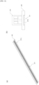
FIG. 5 is a perspective and front view of the main separation wall included in the pack case ofFIG. 4 . -
FIG. 6 is a rear perspective view of the main separation wall ofFIG. 5 . -
FIG. 7 illustrates a modified example of a heat dissipation fin included in the main separation wall ofFIG. 6 . -
FIG. 8 is a plan view of a battery module settled in the pack case ofFIG. 4 . -
FIG. 9 is a rear perspective view of a main separation wall included in a battery pack according to a second embodiment of the present invention. -
FIG. 10 illustrates a modified example of a heat dissipation fin included in the main separation wall ofFIG. 9 . -
FIG. 11 is a rear perspective view of a main separation wall included in a battery pack according to a third embodiment of the present invention. -
FIG. 12 is a rear perspective view of a main separation wall included in a battery pack according to a fourth embodiment of the present invention. -
FIG. 13 is a front view and partial enlarged view of a battery pack according to a fifth embodiment of the present invention. - Hereinafter, preferred embodiments of the present invention will be described in detail with reference to the accompanying drawings. Before doing so, it should be noted that the terms and words used in this specification and claims are not to be construed in their ordinary or dictionary sense, but rather in a sense and concept consistent with the technical idea of the present invention, based on the principle that the inventor may properly define the concept of a term to best describe his invention.
- Accordingly, it is to be understood that the embodiments described herein and the configurations illustrated in the drawings are only the most preferred embodiments of the present invention and do not represent all of the technical ideas of the present invention, and that there may be various equivalents and variations that may be substituted for them at the time of filing the present disclosure.
- In addition, in describing the present invention, detailed descriptions of related known configurations or features are omitted where it is determined that such detailed descriptions would obscure the essence of the present invention.
Since the embodiments of the present invention are provided to more fully illustrate the present invention to those of ordinary skill in the art, the shapes and sizes of the components in the drawings may be exaggerated, omitted, or shown schematically for clarity. Accordingly, the size or proportions of each component are not necessarily indicative of its actual size or proportions. - The present invention relates to a battery pack having a structure capable of rapidly discharging high temperature heat to the outside when thermal runaway occurs in a battery module accommodated therein.
-
FIGS. 4 through 8 relate to a battery pack according to a first embodiment of the invention,FIGS. 9 through 10 relate to a battery pack according to a second embodiment of the invention,FIG. 11 relates to a battery pack according to a third embodiment of the invention,FIG. 12 relates to a battery pack according to a fourth embodiment of the invention, andFIG. 13 relates to a battery pack according to a fifth embodiment of the invention. - Hereinafter, the battery pack of the present invention will be described in each embodiment with reference to the accompanying drawings.
- The battery pack of the present invention includes a
pack case 1000 in which battery module B is settled, and an upper cover coupled to thepack case 1000 to cover the upper part of each battery module B accommodated in thepack case 1000. - The
pack case 1000 provides a module area, which is a space in which a plurality of battery modules B is settled, and serves to protect the battery modules B settled in the module area from the outside. - Since the upper cover falls within the known art, a detailed description thereof is omitted herein.
-
FIG. 4 is a perspective view of apack case 1000 included in a battery pack according to a first embodiment of the present invention,FIG. 5 is a perspective and front view of amain separation wall 200 included in thepack case 1000 ofFIG. 4 , andFIG. 6 is a rear perspective view of themain separation wall 200 ofFIG. 5 . - The
pack case 1000 of the present invention includes amain separation wall 200, abase plate 100, and a side wall, as shown inFIG. 4 . - The
main separation wall 200 serves to compartmentalize the internal space of thepack case 1000, and also serves to protect the battery module B settled inside thepack case 1000. - As needed, the interior of the
main separation wall 200 may be inserted with wires or busbars or the like that are installed to traverse thepack case 1000 so as to protect them. - The
main separation wall 200 is formed to traverse the center part of thepack case 1000 so as to broadly divide the module area into two spaces. - The plurality of battery modules B that are settled in the
pack case 1000 may be positioned on either side with themain separation wall 200 in between. - The
main separation wall 200 includes abase part 220 coupled to the base plate, and aprotrusion part 210 that protrudes toward the upper part of thebase part 220 to support the sides of the battery module B. - The
base plate 100 corresponds to the bottom of thepack case 1000 and serves to support the lower part of the battery module B. - More specifically, the
base plate 100 includes a module area in which the battery module B is settled. - The
base plates 100 exist in pairs and are respectively coupled to both sides of themain separation wall 200. - The side wall serves to support and protect the sides of the battery module B accommodated in the
pack case 1000, and is coupled along the perimeter of thebase plate 100 coupled to themain separation wall 200. - The
main separation wall 200 of the present invention is characterized in that it includes aheat dissipation part 221 that can effectively dissipate Hr heat generated inside thepack case 1000. More specifically, theheat dissipation part 221 is included in the lower part of thebase part 220 of themain separation wall 200. - The
heat dissipation part 221 includes a plurality ofheat dissipation fins 221a extending downwardly from a lower part of themain separation wall 200, as shown inFIG. 5 . - The
heat dissipation fin 221a of themain separation wall 200 included in the battery pack according to the first embodiment is formed extending along the longitudinal direction of themain separation wall 200, as shown inFIG. 6 . -
FIG. 7 illustrates a modified example of theheat dissipation fin 221a included in themain separation wall 200 ofFIG. 6 . - The
heat dissipation fin 221a may be formed extending along the longitudinal direction of themain separation wall 200 in a straight shape as shown inFIG. 6 , but is not limited thereto, and may also be formed extending in a wavy pattern as shown inFIG. 7 . Theheat dissipation fin 221a having such a curved shape allows for heat dissipation Hr through a larger surface area in the same space. - The
heat dissipation fin 221a in the form described above allows heat absorbed by the entire surface area of themain separation wall 200 to be dissipated through the entire lower part of themain separation wall 200. - The
heat dissipation part 221 includes at least oneheat dissipation fin 221a as shown inFIGS. 6 and 7 , and the plurality ofheat dissipation fins 221a formed on the lower part of themain separation wall 200 are spaced apart at predetermined spacings along the width direction of themain separation wall 200. - The
main separation wall 200 may absorb heat generated during the process of charging and discharging the cells contained in each battery module B and effectively dissipate Hr the absorbed heat via theheat dissipation fin 221a. Here, the absorbed heat is dissipated Hr to the lower part of the battery pack. In addition, themain separation wall 200 is capable of absorbing high temperature heat generated during a short period of time and rapidly dissipating Hr the absorbed heat via theheat dissipation fin 221a in the event of thermal runaway T in any one of the battery modules B accommodated on one or both sides. - The battery pack of the present invention is capable of preventing a phenomenon such as an explosion of all the battery modules B accommodated in the battery pack by rapidly dissipating Hr through the
heat dissipation fins 221a before the heat generated is transferred to the other battery modules B located on the other side of themain separation wall 200, when a thermal runaway T occurs in at least one of the plurality of battery modules B accommodated on one side of themain separation wall 200. -
FIG. 8 is a plan view of the battery module B settled in thepack case 1000 ofFIG. 4 . As shown above, high temperature heat generated by thermal runaway T phenomenon in a plurality of battery modules B located on one side of themain separation wall 200 is absorbed and dissipated Hr by themain separation wall 200. In addition, since heat is continuously dissipated Hr by themain separation wall 200, heat is not properly transferred to other battery modules B located on the other side of themain separation wall 200. - The
main separation wall 200 of the present invention is characterized in that it includes aheat dissipation part 221 that can effectively dissipate Hr heat generated inside thepack case 1000. -
FIG. 9 is a rear perspective view of themain separation wall 200 included in a battery pack according to a second embodiment of the present invention. - The
heat dissipation part 221 includes a plurality ofheat dissipation fins 221a extending downwardly from a lower part of themain separation wall 200, as shown inFIG. 9 . - The
heat dissipation fin 221a of themain separation wall 200 included in the battery pack according to the second embodiment is formed by extending along the width direction of themain separation wall 200, as shown inFIG. 9 . -
FIG. 10 illustrates a modified example of theheat dissipation fin 221a included in themain separation wall 200 ofFIG. 9 . - The
heat dissipation fin 221a may be formed extending along the width direction of themain separation wall 200 in a straight shape as shown inFIG. 9 , but is not limited thereto, and may also be formed extending in a wavy shape as shown inFIG. 10 . Theheat dissipation fin 221a having such a curved shape allows for heat dissipation Hr over a larger surface area within the same space. - The
heat dissipation part 221a in the form described above allows heat absorbed by the entire surface area of themain separation wall 200 to be dissipated through the entire lower part of themain separation wall 200. - The
heat dissipation part 221 includes at least oneheat dissipation fin 221a as shown inFIGS. 9 and 10 , and the plurality ofheat dissipation fins 221a formed on the lower part of themain separation wall 200 are spaced apart at predetermined spacings along the longitudinal direction of themain separation wall 200. - The
main separation wall 200 of the present invention is characterized in that it includes aheat dissipation part 221 that can effectively dissipate Hr heat generated inside thepack case 1000. -
FIG. 11 is a rear perspective view of themain separation wall 200 included in a battery pack according to a third embodiment of the present invention. - The
heat dissipation part 221 includes a plurality ofheat dissipation fins 221a extending downwardly from a lower part of themain separation wall 200, as shown inFIG. 11 . - The
heat dissipation fins 221a of themain separation wall 200 included in the battery pack according to the third embodiment are formed to extend diagonally relative to the longitudinal direction or width direction of themain separation wall 200, as shown inFIG. 11 . - The
heat dissipation fin 221a may be formed extending along the width direction of themain separation wall 200 in a straight shape as shown inFIG. 9 , but is not limited thereto, and may also be formed extending in a wavy pattern, the same as themain separation wall 200 included in the battery pack according to the first and second embodiments. Theheat dissipation fin 221a having such a curved shape enables heat dissipation Hr through a larger surface area within the same space. - The
heat dissipation fin 221a in the form described above allows heat absorbed by the entire surface area of themain separation wall 200 to be dissipated through the entire lower part of themain separation wall 200. - The
heat dissipation part 221 includes at least oneheat dissipation fin 221a as shown inFIG. 11 , and the plurality ofheat dissipation fins 221a formed on the lower part of themain separation wall 200 are spaced apart at predetermined spacings along a direction orthogonal to the direction in which theheat dissipation fins 221a are extended. - The
main separation wall 200 of the present invention is characterized in that it includes aheat dissipation part 221 that can effectively dissipate Hr heat generated inside thepack case 1000. -
FIG. 12 is a rear perspective view of themain separation wall 200 included in a battery pack according to a fourth embodiment of the present invention. - The
heat dissipation part 221 includes a plurality ofheat dissipation fins 221a extending downwardly from a lower part of themain separation wall 200, as shown inFIG. 12 . - The
heat dissipation fins 221a of themain separation wall 200 included in the battery pack according to the fourth embodiment are formed in the shape of fins as shown inFIG. 12 . - The
heat dissipation fin 221a in the shape described above allows heat absorbed by the entire surface area of themain separation wall 200 to be dissipated through the entire lower part of themain separation wall 200. - The
heat dissipation part 221 includes at least oneheat dissipation fin 221a as shown inFIG. 12 , and the plurality ofheat dissipation fins 221a formed on the lower part of themain separation wall 200 are spaced apart at predetermined spacings. - The battery pack of the present invention includes a
pack case 1000 in which battery modules B are settled, and an upper cover coupled to thepack case 1000 to cover the upper part of each battery module B accommodated in thepack case 1000. - The
pack case 1000 provides a module area, which is a space in which a plurality of battery modules B is settled, and serves to protect the battery modules B settled in the module area from the outside. - The upper cover falls within the known art, so a detailed description thereof is omitted herein.
- The
pack case 1000 of the present invention includes amain separation wall 200, abase plate 100, and a side wall. - The
main separation wall 200 serves to compartmentalize the internal space of thepack case 1000, and also serves to protect the battery module B settled inside thepack case 1000. - As needed, the interior of the
main separation wall 200 may be inserted with wires or busbars or the like that are installed to traverse thepack case 1000 so as to protect them. - The
main separation wall 200 is formed to traverse the center part of thepack case 1000 so as to broadly divide the module area into two spaces. - The plurality of battery modules B that are settled in the
pack case 1000 may be positioned on either side with themain separation wall 200 in between. - The
base plate 100 corresponds to the bottom of thepack case 1000 and serves to support the lower part of the battery module B. - More specifically, the
base plate 100 includes a module area in which the battery module B is settled. - The
base plates 100 exist in pairs and are respectively coupled to both sides of themain separation wall 200. - The side wall serves to support and protect the sides of the battery module B settled in the
pack case 1000, and are coupled along the perimeter of thebase plate 100 coupled to themain separation wall 200. - The
main separation wall 200 of the present invention is characterized in that it includes aheat dissipation part 221 that can effectively dissipate Hr heat generated inside thepack case 1000. - The
heat dissipation part 221 includes a plurality ofheat dissipation fins 221a extending downwardly from a lower part of themain separation wall 200. - The
heat dissipation fin 221a allows heat absorbed by the entire surface area of themain separation wall 200 to be dissipated through the entire lower part of themain separation wall 200. - The
heat dissipation part 221 includes at least oneheat dissipation fin 221a, and the plurality ofheat dissipation fins 221a formed on the lower part of themain separation wall 200 are spaced apart at a predetermined spacing. - The
main separation wall 200 can absorb heat generated during the process of charging and discharging the cells contained in each battery module B and effectively dissipate Hr the absorbed heat via theheat dissipation fin 221a. Here, the absorbed heat is dissipated Hr to the lower part of the battery pack. In addition, themain separation wall 200 is capable of absorbing high temperature heat generated during a short period of time and rapidly dissipating Hr the absorbed heat via theheat dissipation fin 221a in the event of thermal runaway T in any one of the battery modules B accommodated on one or both sides. - The battery pack of the present invention is capable of preventing a phenomenon such as an explosion of all the battery modules B accommodated in the battery pack by rapidly dissipating Hr through the
heat dissipation fins 221a before the heat generated is transferred to the other battery modules B located on the other side of themain separation wall 200, when a thermal runaway T occurs in at least one of the plurality of battery modules B accommodated on one side of themain separation wall 200. - The
base plate 100 may be a hollow shape having a hollow inside, and may include a plurality offluid path tubes 110 formed inside the hollow and extending along a longitudinal direction of thepack case 1000. In this case, cooling water or the like may move through thefluid path tubes 110, and the cooling water may cool the heat generated by the battery module B as it moves through thefluid path tubes 110. - The
base plate 100 included in the battery pack according to the fifth embodiment of the invention is characterized in that it further includes, inside the hollow, in addition to theheat dissipation fins 221a of themain separation wall 200, auxiliaryheat dissipation fin 120 having the function of discharging the heat generated inside. -
FIG. 13 is a front view and partial enlarged view of a battery pack according to a fifth embodiment of the present invention. - As shown in
FIG. 13 , thebase plate 100 further includes a ribbed auxiliaryheat dissipation fin 120 that connects a bottom part of the hollow and a ceiling part of the hollow within the hollow and extends along the longitudinal direction of thepack case 1000. - The auxiliary
heat dissipation fin 120 may be formed at predetermined spacings spaced apart along the width direction of thepack case 1000, and heat generated by each battery module B settled on the upper part of thebase plate 100 along with coolant traveling through thefluid path tube 110 may be more effectively dissipated Hr through the auxiliaryheat dissipation fin 120. - The present invention has been described in more detail above with reference to the drawings and embodiments. However, it is to be understood that the configurations shown in the drawings or embodiments described herein are only one embodiment of the invention and do not represent all of the technical ideas of the present invention, and that there may be various equivalents and modifications that may replace them at the time of filing the present disclosure.
-
- 10: (CONVENTIONAL ART) PACK CASE
- 20: (CONVENTIONAL ART) BASE PLATE
- 30: (CONVENTIONAL ART) MAIN SEPARATION WALL
- 40: (CONVENTIONAL ART) FLUID PATH TUBE
- 1000: PACK CASE
- 100: BASE PLATE
- 110: FLUID PATH TUBE
- 120: AUXILIARY HEAT DISSIPATION FIN
- 200: MAIN SEPARATION WALL
- 210: PROTRUSION PART
- 220: BASE PART
- 221: HEAT DISSIPATION PART
- 221A: HEAT DISSIPATION FIN
- 300: SIDE WALL
- B: BATTERY MODULE
- T: THERMAL RUNAWAY
- Ha: HEAT (MOVEMENT)
- Hr: HEAT DISSIPATION
Claims (13)
- A battery pack accommodating a battery module, comprising:a pack case in which a battery module is settled; whereinthe pack case comprises:a main separation wall;a base plate coupled to each side of the main separation wall, and including a module area in which the battery module is settled; anda side wall coupled along a perimeter of a base plate coupled to the main separation wall; andthe main separation wall comprises:
a heat dissipation part, which includes a heat dissipation fin protruded to allow heat dissipation, at a lower part. - The battery pack of claim 1, wherein
the heat dissipation fin is formed extending along a longitudinal direction of the main separation wall. - The battery pack of claim 2, wherein
the heat dissipation part comprises a plurality of heat dissipation fins formed by being spaced apart at predetermined spacings in a width direction of the main separation wall. - The battery pack of claim 2, wherein
the heat dissipation fin extends in a straight line, or extend in a wavy pattern. - The battery pack of claim 1, wherein
the heat dissipation fin extends along a width direction of the main separation wall. - The battery pack of claim 5, wherein
the heat dissipation part comprises a plurality of heat dissipation fins formed by being spaced apart at predetermined spacings along a longitudinal direction of the main separation wall. - The battery pack of claim 5, wherein
the heat dissipation fin extend in a straight line, or extend in a wavy pattern. - The battery pack of claim 1, wherein
the heat dissipation fin is formed extending in a diagonal direction relative to a longitudinal or width direction of the main separation wall. - The battery pack of claim 8, wherein
the heat dissipation part comprises a plurality of heat dissipation fins formed by being spaced apart at predetermined spacings along a direction orthogonal to a direction in which the heat dissipation fins are extended. - The battery pack of claim 9, wherein
the heat dissipation fin extends in a straight line, or extend in a wavy pattern. - The battery pack of claim 1, wherein
the base plate is a hollow type with a hollow inside, and comprises a plurality of fluid path tubes formed by extending from the hollow along a longitudinal direction of a pack case. - The battery pack of claim 11, wherein
the base plate further comprises:
an auxiliary heat dissipation fin in the shape of a rib connecting a bottom part of the hollow and a ceiling part of the hollow inside the hollow and formed by extending along the longitudinal direction of the pack case. - The battery pack of claim 12, wherein
the auxiliary heat dissipation fins are formed by being spaced apart at predetermined spacings along a width direction of the pack case.
Applications Claiming Priority (2)
| Application Number | Priority Date | Filing Date | Title |
|---|---|---|---|
| KR1020220098090A KR20240020080A (en) | 2022-08-05 | 2022-08-05 | Battery pack |
| PCT/KR2023/011350 WO2024029934A1 (en) | 2022-08-05 | 2023-08-02 | Battery pack |
Publications (3)
| Publication Number | Publication Date |
|---|---|
| EP4462562A1 true EP4462562A1 (en) | 2024-11-13 |
| EP4462562A4 EP4462562A4 (en) | 2025-06-25 |
| EP4462562B1 EP4462562B1 (en) | 2026-03-11 |
Family
ID=89849650
Family Applications (1)
| Application Number | Title | Priority Date | Filing Date |
|---|---|---|---|
| EP23850434.4A Active EP4462562B1 (en) | 2022-08-05 | 2023-08-02 | Battery pack |
Country Status (6)
| Country | Link |
|---|---|
| US (1) | US20250158155A1 (en) |
| EP (1) | EP4462562B1 (en) |
| JP (1) | JP7768636B2 (en) |
| KR (1) | KR20240020080A (en) |
| CN (1) | CN118749160A (en) |
| WO (1) | WO2024029934A1 (en) |
Family Cites Families (11)
| Publication number | Priority date | Publication date | Assignee | Title |
|---|---|---|---|---|
| JP2007311124A (en) | 2006-05-17 | 2007-11-29 | Toyota Motor Corp | Battery pack and vehicle |
| KR101261736B1 (en) * | 2011-06-13 | 2013-05-07 | 로베르트 보쉬 게엠베하 | Battery Pack |
| KR102214949B1 (en) * | 2016-05-24 | 2021-02-10 | 삼성에스디아이 주식회사 | Battery pack |
| KR102731553B1 (en) | 2016-12-15 | 2024-11-18 | 현대자동차주식회사 | Battery module having cooling structure |
| KR102258827B1 (en) | 2017-06-02 | 2021-05-31 | 주식회사 엘지에너지솔루션 | Battery pack and vehicle including the same |
| WO2019195119A1 (en) | 2018-04-06 | 2019-10-10 | Cps Technology Holdings Llc | Thermal management system for a battery module |
| HUE050941T2 (en) | 2018-04-09 | 2021-01-28 | Samsung Sdi Co Ltd | Coolant distributor |
| KR102871338B1 (en) * | 2020-09-04 | 2025-10-15 | 주식회사 엘지에너지솔루션 | Battery Pack, and Electric Device and Vehicle Including Same |
| KR102848976B1 (en) * | 2020-12-24 | 2025-08-21 | 에스케이온 주식회사 | Pouch Type Battery Cell and Battery Pack Including the Same |
| EP4024571A1 (en) * | 2020-12-31 | 2022-07-06 | Samsung SDI Co., Ltd. | Battery module |
| CN113566836A (en) | 2021-06-28 | 2021-10-29 | 阿波罗智联(北京)科技有限公司 | Road guiding method, device, electronic equipment and storage medium |
-
2022
- 2022-08-05 KR KR1020220098090A patent/KR20240020080A/en active Pending
-
2023
- 2023-08-02 WO PCT/KR2023/011350 patent/WO2024029934A1/en not_active Ceased
- 2023-08-02 EP EP23850434.4A patent/EP4462562B1/en active Active
- 2023-08-02 JP JP2024548448A patent/JP7768636B2/en active Active
- 2023-08-02 CN CN202380022926.8A patent/CN118749160A/en active Pending
- 2023-08-02 US US18/839,003 patent/US20250158155A1/en active Pending
Also Published As
| Publication number | Publication date |
|---|---|
| KR20240020080A (en) | 2024-02-14 |
| EP4462562A4 (en) | 2025-06-25 |
| US20250158155A1 (en) | 2025-05-15 |
| JP7768636B2 (en) | 2025-11-12 |
| CN118749160A (en) | 2024-10-08 |
| WO2024029934A1 (en) | 2024-02-08 |
| JP2025511442A (en) | 2025-04-16 |
| EP4462562B1 (en) | 2026-03-11 |
Similar Documents
| Publication | Publication Date | Title |
|---|---|---|
| JP6750117B2 (en) | Battery pack with crash beam and drainage structure | |
| JP6730526B2 (en) | Battery pack with crash beam structure | |
| ES3034504T3 (en) | Battery pack with efficient cooling path structure and improved safety and vehicle including the same | |
| KR101910244B1 (en) | Battery Module Having Improved Cooling Performance | |
| JP2023503628A (en) | Devices that use battery modules, battery packs and secondary batteries | |
| KR102184753B1 (en) | Battery module, battery pack comprising the battery module and vehicle comprising the battery pack | |
| US20160294025A1 (en) | Cooler for secondary battery | |
| CN110100351A (en) | Battery pack including heat transfer medium having louver blade shape | |
| CN115088120B (en) | Battery pack and vehicle including the battery pack | |
| KR20200032525A (en) | Battery module | |
| KR102877728B1 (en) | Battery module and battery pack having the same | |
| KR102913444B1 (en) | Battery Pack and Battery Module Provided therein | |
| JP2023510898A (en) | Battery packs, motor vehicles containing them | |
| KR20200084402A (en) | Cooling device of battery module for electric vehicles | |
| CN115606040B (en) | Battery module and battery pack including the same | |
| EP4462562B1 (en) | Battery pack | |
| US20250096407A1 (en) | Battery Pack And Vehicle Including Same | |
| EP4465427B1 (en) | Battery pack | |
| US20240204295A1 (en) | Battery module and battery pack including the same | |
| KR20240156731A (en) | Battery module and battery pack including the same | |
| KR102821925B1 (en) | Battery Pack and Electronic Device Comprising the Same and Vehicle | |
| KR102941955B1 (en) | Battery module cooling apparatus | |
| KR102857695B1 (en) | Thermal management structure to improve battery heat dissipation efficiency | |
| KR102696980B1 (en) | Cylindrical battery cooling device | |
| KR102850649B1 (en) | Cooling apparatus for double-sided type battery module |
Legal Events
| Date | Code | Title | Description |
|---|---|---|---|
| STAA | Information on the status of an ep patent application or granted ep patent |
Free format text: STATUS: THE INTERNATIONAL PUBLICATION HAS BEEN MADE |
|
| PUAI | Public reference made under article 153(3) epc to a published international application that has entered the european phase |
Free format text: ORIGINAL CODE: 0009012 |
|
| STAA | Information on the status of an ep patent application or granted ep patent |
Free format text: STATUS: REQUEST FOR EXAMINATION WAS MADE |
|
| 17P | Request for examination filed |
Effective date: 20240807 |
|
| AK | Designated contracting states |
Kind code of ref document: A1 Designated state(s): AL AT BE BG CH CY CZ DE DK EE ES FI FR GB GR HR HU IE IS IT LI LT LU LV MC ME MK MT NL NO PL PT RO RS SE SI SK SM TR |
|
| A4 | Supplementary search report drawn up and despatched |
Effective date: 20250528 |
|
| RIC1 | Information provided on ipc code assigned before grant |
Ipc: H01M 10/6551 20140101ALI20250522BHEP Ipc: H01M 50/24 20210101AFI20250522BHEP |
|
| DAV | Request for validation of the european patent (deleted) | ||
| DAX | Request for extension of the european patent (deleted) | ||
| GRAP | Despatch of communication of intention to grant a patent |
Free format text: ORIGINAL CODE: EPIDOSNIGR1 |
|
| STAA | Information on the status of an ep patent application or granted ep patent |
Free format text: STATUS: GRANT OF PATENT IS INTENDED |
|
| INTG | Intention to grant announced |
Effective date: 20251119 |
|
| P01 | Opt-out of the competence of the unified patent court (upc) registered |
Free format text: CASE NUMBER: UPC_APP_0015399_4462562/2025 Effective date: 20251201 |
|
| GRAS | Grant fee paid |
Free format text: ORIGINAL CODE: EPIDOSNIGR3 |
|
| GRAA | (expected) grant |
Free format text: ORIGINAL CODE: 0009210 |
|
| STAA | Information on the status of an ep patent application or granted ep patent |
Free format text: STATUS: THE PATENT HAS BEEN GRANTED |
|
| AK | Designated contracting states |
Kind code of ref document: B1 Designated state(s): AL AT BE BG CH CY CZ DE DK EE ES FI FR GB GR HR HU IE IS IT LI LT LU LV MC ME MK MT NL NO PL PT RO RS SE SI SK SM TR |
|
| REG | Reference to a national code |
Ref country code: CH Ref legal event code: F10 Free format text: ST27 STATUS EVENT CODE: U-0-0-F10-F00 (AS PROVIDED BY THE NATIONAL OFFICE) Effective date: 20260311 Ref country code: GB Ref legal event code: FG4D |
|
| REG | Reference to a national code |
Ref country code: DE Ref legal event code: R096 Ref document number: 602023013535 Country of ref document: DE |
|
| REG | Reference to a national code |
Ref country code: IE Ref legal event code: FG4D |