EP4462553A1 - Battery pack and vehicle comprising same - Google Patents
Battery pack and vehicle comprising same Download PDFInfo
- Publication number
- EP4462553A1 EP4462553A1 EP23907262.2A EP23907262A EP4462553A1 EP 4462553 A1 EP4462553 A1 EP 4462553A1 EP 23907262 A EP23907262 A EP 23907262A EP 4462553 A1 EP4462553 A1 EP 4462553A1
- Authority
- EP
- European Patent Office
- Prior art keywords
- cell assemblies
- battery pack
- partition member
- battery
- cell
- Prior art date
- Legal status (The legal status is an assumption and is not a legal conclusion. Google has not performed a legal analysis and makes no representation as to the accuracy of the status listed.)
- Pending
Links
Images





Classifications
-
- H—ELECTRICITY
- H01—ELECTRIC ELEMENTS
- H01M—PROCESSES OR MEANS, e.g. BATTERIES, FOR THE DIRECT CONVERSION OF CHEMICAL ENERGY INTO ELECTRICAL ENERGY
- H01M50/00—Constructional details or processes of manufacture of the non-active parts of electrochemical cells other than fuel cells, e.g. hybrid cells
- H01M50/20—Mountings; Secondary casings or frames; Racks, modules or packs; Suspension devices; Shock absorbers; Transport or carrying devices; Holders
- H01M50/289—Mountings; Secondary casings or frames; Racks, modules or packs; Suspension devices; Shock absorbers; Transport or carrying devices; Holders characterised by spacing elements or positioning means within frames, racks or packs
- H01M50/293—Mountings; Secondary casings or frames; Racks, modules or packs; Suspension devices; Shock absorbers; Transport or carrying devices; Holders characterised by spacing elements or positioning means within frames, racks or packs characterised by the material
-
- H—ELECTRICITY
- H01—ELECTRIC ELEMENTS
- H01M—PROCESSES OR MEANS, e.g. BATTERIES, FOR THE DIRECT CONVERSION OF CHEMICAL ENERGY INTO ELECTRICAL ENERGY
- H01M50/00—Constructional details or processes of manufacture of the non-active parts of electrochemical cells other than fuel cells, e.g. hybrid cells
- H01M50/20—Mountings; Secondary casings or frames; Racks, modules or packs; Suspension devices; Shock absorbers; Transport or carrying devices; Holders
- H01M50/233—Mountings; Secondary casings or frames; Racks, modules or packs; Suspension devices; Shock absorbers; Transport or carrying devices; Holders characterised by physical properties of casings or racks, e.g. dimensions
- H01M50/24—Mountings; Secondary casings or frames; Racks, modules or packs; Suspension devices; Shock absorbers; Transport or carrying devices; Holders characterised by physical properties of casings or racks, e.g. dimensions adapted for protecting batteries from their environment, e.g. from corrosion
-
- B—PERFORMING OPERATIONS; TRANSPORTING
- B60—VEHICLES IN GENERAL
- B60L—PROPULSION OF ELECTRICALLY-PROPELLED VEHICLES; SUPPLYING ELECTRIC POWER FOR AUXILIARY EQUIPMENT OF ELECTRICALLY-PROPELLED VEHICLES; ELECTRODYNAMIC BRAKE SYSTEMS FOR VEHICLES IN GENERAL; MAGNETIC SUSPENSION OR LEVITATION FOR VEHICLES; MONITORING OPERATING VARIABLES OF ELECTRICALLY-PROPELLED VEHICLES; ELECTRIC SAFETY DEVICES FOR ELECTRICALLY-PROPELLED VEHICLES
- B60L50/00—Electric propulsion with power supplied within the vehicle
- B60L50/50—Electric propulsion with power supplied within the vehicle using propulsion power supplied by batteries or fuel cells
- B60L50/60—Electric propulsion with power supplied within the vehicle using propulsion power supplied by batteries or fuel cells using power supplied by batteries
- B60L50/64—Constructional details of batteries specially adapted for electric vehicles
-
- H—ELECTRICITY
- H01—ELECTRIC ELEMENTS
- H01M—PROCESSES OR MEANS, e.g. BATTERIES, FOR THE DIRECT CONVERSION OF CHEMICAL ENERGY INTO ELECTRICAL ENERGY
- H01M10/00—Secondary cells; Manufacture thereof
- H01M10/60—Heating or cooling; Temperature control
- H01M10/65—Means for temperature control structurally associated with the cells
- H01M10/658—Means for temperature control structurally associated with the cells by thermal insulation or shielding
-
- H—ELECTRICITY
- H01—ELECTRIC ELEMENTS
- H01M—PROCESSES OR MEANS, e.g. BATTERIES, FOR THE DIRECT CONVERSION OF CHEMICAL ENERGY INTO ELECTRICAL ENERGY
- H01M50/00—Constructional details or processes of manufacture of the non-active parts of electrochemical cells other than fuel cells, e.g. hybrid cells
- H01M50/20—Mountings; Secondary casings or frames; Racks, modules or packs; Suspension devices; Shock absorbers; Transport or carrying devices; Holders
- H01M50/204—Racks, modules or packs for multiple batteries or multiple cells
-
- H—ELECTRICITY
- H01—ELECTRIC ELEMENTS
- H01M—PROCESSES OR MEANS, e.g. BATTERIES, FOR THE DIRECT CONVERSION OF CHEMICAL ENERGY INTO ELECTRICAL ENERGY
- H01M50/00—Constructional details or processes of manufacture of the non-active parts of electrochemical cells other than fuel cells, e.g. hybrid cells
- H01M50/20—Mountings; Secondary casings or frames; Racks, modules or packs; Suspension devices; Shock absorbers; Transport or carrying devices; Holders
- H01M50/204—Racks, modules or packs for multiple batteries or multiple cells
- H01M50/207—Racks, modules or packs for multiple batteries or multiple cells characterised by their shape
- H01M50/211—Racks, modules or packs for multiple batteries or multiple cells characterised by their shape adapted for pouch cells
-
- H—ELECTRICITY
- H01—ELECTRIC ELEMENTS
- H01M—PROCESSES OR MEANS, e.g. BATTERIES, FOR THE DIRECT CONVERSION OF CHEMICAL ENERGY INTO ELECTRICAL ENERGY
- H01M50/00—Constructional details or processes of manufacture of the non-active parts of electrochemical cells other than fuel cells, e.g. hybrid cells
- H01M50/20—Mountings; Secondary casings or frames; Racks, modules or packs; Suspension devices; Shock absorbers; Transport or carrying devices; Holders
- H01M50/249—Mountings; Secondary casings or frames; Racks, modules or packs; Suspension devices; Shock absorbers; Transport or carrying devices; Holders specially adapted for aircraft or vehicles, e.g. cars or trains
-
- H—ELECTRICITY
- H01—ELECTRIC ELEMENTS
- H01M—PROCESSES OR MEANS, e.g. BATTERIES, FOR THE DIRECT CONVERSION OF CHEMICAL ENERGY INTO ELECTRICAL ENERGY
- H01M50/00—Constructional details or processes of manufacture of the non-active parts of electrochemical cells other than fuel cells, e.g. hybrid cells
- H01M50/20—Mountings; Secondary casings or frames; Racks, modules or packs; Suspension devices; Shock absorbers; Transport or carrying devices; Holders
- H01M50/289—Mountings; Secondary casings or frames; Racks, modules or packs; Suspension devices; Shock absorbers; Transport or carrying devices; Holders characterised by spacing elements or positioning means within frames, racks or packs
- H01M50/291—Mountings; Secondary casings or frames; Racks, modules or packs; Suspension devices; Shock absorbers; Transport or carrying devices; Holders characterised by spacing elements or positioning means within frames, racks or packs characterised by their shape
-
- H—ELECTRICITY
- H01—ELECTRIC ELEMENTS
- H01M—PROCESSES OR MEANS, e.g. BATTERIES, FOR THE DIRECT CONVERSION OF CHEMICAL ENERGY INTO ELECTRICAL ENERGY
- H01M50/00—Constructional details or processes of manufacture of the non-active parts of electrochemical cells other than fuel cells, e.g. hybrid cells
- H01M50/30—Arrangements for facilitating escape of gases
- H01M50/342—Non-re-sealable arrangements
- H01M50/3425—Non-re-sealable arrangements in the form of rupturable membranes or weakened parts, e.g. pierced with the aid of a sharp member
-
- H—ELECTRICITY
- H01—ELECTRIC ELEMENTS
- H01M—PROCESSES OR MEANS, e.g. BATTERIES, FOR THE DIRECT CONVERSION OF CHEMICAL ENERGY INTO ELECTRICAL ENERGY
- H01M50/00—Constructional details or processes of manufacture of the non-active parts of electrochemical cells other than fuel cells, e.g. hybrid cells
- H01M50/30—Arrangements for facilitating escape of gases
- H01M50/375—Vent means sensitive to or responsive to temperature
-
- H—ELECTRICITY
- H01—ELECTRIC ELEMENTS
- H01M—PROCESSES OR MEANS, e.g. BATTERIES, FOR THE DIRECT CONVERSION OF CHEMICAL ENERGY INTO ELECTRICAL ENERGY
- H01M50/00—Constructional details or processes of manufacture of the non-active parts of electrochemical cells other than fuel cells, e.g. hybrid cells
- H01M50/30—Arrangements for facilitating escape of gases
- H01M50/383—Flame arresting or ignition-preventing means
-
- H—ELECTRICITY
- H01—ELECTRIC ELEMENTS
- H01M—PROCESSES OR MEANS, e.g. BATTERIES, FOR THE DIRECT CONVERSION OF CHEMICAL ENERGY INTO ELECTRICAL ENERGY
- H01M2200/00—Safety devices for primary or secondary batteries
- H01M2200/10—Temperature sensitive devices
-
- H—ELECTRICITY
- H01—ELECTRIC ELEMENTS
- H01M—PROCESSES OR MEANS, e.g. BATTERIES, FOR THE DIRECT CONVERSION OF CHEMICAL ENERGY INTO ELECTRICAL ENERGY
- H01M2200/00—Safety devices for primary or secondary batteries
- H01M2200/20—Pressure-sensitive devices
-
- H—ELECTRICITY
- H01—ELECTRIC ELEMENTS
- H01M—PROCESSES OR MEANS, e.g. BATTERIES, FOR THE DIRECT CONVERSION OF CHEMICAL ENERGY INTO ELECTRICAL ENERGY
- H01M2220/00—Batteries for particular applications
- H01M2220/20—Batteries in motive systems, e.g. vehicle, ship, plane
-
- Y—GENERAL TAGGING OF NEW TECHNOLOGICAL DEVELOPMENTS; GENERAL TAGGING OF CROSS-SECTIONAL TECHNOLOGIES SPANNING OVER SEVERAL SECTIONS OF THE IPC; TECHNICAL SUBJECTS COVERED BY FORMER USPC CROSS-REFERENCE ART COLLECTIONS [XRACs] AND DIGESTS
- Y02—TECHNOLOGIES OR APPLICATIONS FOR MITIGATION OR ADAPTATION AGAINST CLIMATE CHANGE
- Y02E—REDUCTION OF GREENHOUSE GAS [GHG] EMISSIONS, RELATED TO ENERGY GENERATION, TRANSMISSION OR DISTRIBUTION
- Y02E60/00—Enabling technologies; Technologies with a potential or indirect contribution to GHG emissions mitigation
- Y02E60/10—Energy storage using batteries
Definitions
- the present disclosure relates to a battery pack and a vehicle including the same, and more particularly, to a battery pack with improved safety against thermal events and a vehicle including the same.
- Secondary batteries have high applicability according to product groups and electrical characteristics such as high energy density, and thus, are commonly applied not only to mobile devices but also to electric vehicles (EVs) or hybrid vehicles (HEVs) driven by electric power sources. Because secondary batteries may radically reduce the use of fossil fuel and do not generate any by-products that come with energy consumption, the secondary batteries are gaining attention as a new alternative energy source for improving eco-friendliness and energy efficiency.
- EVs electric vehicles
- HEVs hybrid vehicles
- Types of secondary batteries that are currently widely used include lithium-ion batteries, lithium polymer batteries, nickel cadmium batteries, nickel hydride batteries, and nickel zinc batteries.
- An operating voltage of a unit secondary battery cell ranges from about 2.5 V to about 4.5 V. Accordingly, when a higher output voltage is required, a battery pack may be configured by connecting a plurality of battery cells in series. Also, a battery pack may be configured by connecting a plurality of battery cells in parallel according to charge/discharge capacity required for the battery pack. Accordingly, the number of battery cells included in a battery pack may be set in various ways according to a required output voltage or charge/discharge capacity.
- a method of first configuring a battery module including at least one battery cell and adding other elements by using the at least one battery module to configure a battery pack or battery rack is general.
- mechanisms for accommodating the battery module or structures for partitioning different battery modules within the battery pack are made of aluminum to ensure rigidity, and most of them are melt at about 600°C.
- the particles generated due to the melting of these structures collapse the mechanisms of the battery modules or the structures used to partition different battery modules within the battery pack, or increase the internal pressure of the battery pack by blocking the discharge portion of the venting unit of the battery pack, which becomes an important factor that can cause greater damage, such as secondary ignition or explosion of the battery pack as described above.
- the present disclosure is designed to solve the problems of the related art, and therefore the present disclosure is directed to providing a battery pack with improved safety against thermal events and a vehicle including the battery pack.
- Another object of the present disclosure is to provide a battery pack that can increase energy efficiency while slimming down the battery pack, and a vehicle including the battery pack.
- the present disclosure provides a battery pack, comprising a plurality of cell assemblies containing one or more battery cells and arranged in at least one row; a pack case configured to accommodate the plurality of cell assemblies; and a partition member configured to partition the plurality of cell assemblies within the pack case and made of flexible material to surround the plurality of cell assemblies in close contact.
- the partition member may be in close contact with a side surface of the plurality of cell assemblies in an arrangement direction of the plurality of cell assemblies.
- the partition member may be made of fire-resistant rubber material.
- the partition member may be made of insulating rubber material.
- the partition member may be placed between the plurality of cell assemblies in an arrangement direction of the plurality of cell assemblies.
- the partition member may be provided in plurality corresponding to the number of the plurality of cell assemblies, and the plurality of partition members may be in close contact with both side surfaces of each cell assembly.
- the plurality of partition members may be arranged to be spaced from each other by a predetermined distance in an arrangement direction of the plurality of cell assemblies.
- a venting portion may be provided at a lower portion of the one or more battery cells, and the partition member may surround side surfaces of the plurality of cell assemblies while exposing the venting portion.
- a bottom of the pack case may face the venting portion and be ruptured or melted, when gas or flame is discharged through the venting portion, to discharge the gas or flame out of the pack case.
- the pack case may include a case body configured to support the plurality of cell assemblies and the partition member; and a case cover coupled with the case body to accommodate the plurality of cell assemblies and the partition member, and a bottom of the pack case may face the venting portion and be ruptured or melted, when gas or flame is discharged through the venting portion, to discharge the gas or flame out of the pack case.
- a potting resin may be filled in the space between the plurality of cell assemblies and the case cover.
- the potting resin may be filled in the space between the plurality of cell assemblies.
- the present disclosure provides a vehicle comprising the battery pack according to the above embodiments.
- the present disclosure may have various other effects, and these effects will be explained in each embodiment, or the explanation will be omitted for effects that can be easily inferred by a person skilled in the art.
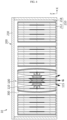
- FIG. 1 is a view for describing a battery pack 10 according to an embodiment of the present disclosure
- FIGS. 2 and 3 are views to for describing a partition member 300 surrounding a cell assembly 100 of the battery pack 10 of FIG. 1 .
- the battery pack 10 may include a cell assembly 100, a pack case 200, and a partition member 300.
- the cell assembly 100 may include one or more battery cells 110.
- the description is limited to the fact that the cell assembly 100 includes a plurality of battery cells 110 in order to increase the output and/or capacity of the battery pack 10.
- the plurality of battery cells 110 are secondary batteries and can be prepared as pouch-type secondary batteries.
- the plurality of battery cells 110 may be stacked so that they can be electrically connected to each other. Meanwhile, in this embodiment, the plurality of battery cells 110 are limited to being provided as pouch-type secondary batteries, but the cell assembly may also be prepared as a stack of cylindrical secondary batteries or prismatic secondary batteries other than the pouch-type secondary batteries.
- the cell assembly 100 may be provided in plurality and arranged in at least one row.
- the arrangement form of the plurality of cell assemblies 100 may vary depending on the required capacity, size or shape of the battery pack 10, and an arrangement of two or more rows or a matrix arrangement may be possible.
- the plurality of cell assemblies 100 are limited to being arranged in a row along the longitudinal direction (X-axis direction) of the battery pack 10.
- the pack case 200 may accommodate the plurality of cell assemblies 100. To this end, an accommodation space capable of accommodating the plurality of cell assemblies 100 may be provided in the pack case 200. The specific structure of the pack case 200 will be discussed in more detail in the related description below.
- the partition member 300 may partition the plurality of cell assemblies 100 within the pack case 200.
- the partition member 300 may support the plurality of cell assemblies 100 while guiding the placement position of the plurality of cell assemblies 100 within the pack case 200.
- the partition member 300 is made of flexible material and may surround the plurality of cell assemblies 100 in close contact. Specifically, the partition member 300 may be in close contact with the outside of the plurality of cell assemblies 100 and surround the outside of the plurality of cell assemblies 100.
- the partition member 300 as above may function as a housing for accommodating the plurality of cell assemblies 100.
- a structure such as a conventional module housing for accommodating the cell assemblies 100 is made of metal, generally aluminum, unlike the partition member 300, and is provided as a frame assembly with a considerable weight. Therefore, the conventional battery pack is generally configured to include a plurality of battery modules composed of these cell assemblies and a module housing for accommodating these cell assemblies.
- the metal structure such as the module housing melts (approximately, at about 600°C), so a large amount of particles or the like are generated due to the melting of the structure in addition to high-temperature gas or flame. Excessive ejected matter, such as this large amount of particles, causes problems such as collapse of the mechanism that constitutes the battery module within the battery pack or the structure for partitioning the battery modules.
- the partition member 300 that surrounds the plurality of cell assemblies 100 in close contact may be provided using a flexible material to accommodate and partition the plurality of cell assemblies 100 within the pack case 200.
- the partition member 300 made of the flexible material unlike the conventional module housing made of metal, during a thermal event, the amount of ejected matter such as particles that are melted and generated by a high-temperature gas or flame may be reduced, so the risk of collapse of the structure inside the battery pack 10 or blocking of the venting path due to the ejected matter such as particles generated due to metal melting can be significantly lowered. As such, in an embodiment of the present disclosure, the risk of secondary damage that may occur when the thermal event occurs can be minimized through the partition member 300.
- a gap space is not created between the plurality of cell assemblies 100 and the partition member 300, so problems such as accumulation or stagnation of ejected matter such as high-temperature gas, flame, or particles that can occur within the gap space during a thermal event can be fundamentally prevented.
- a frame assembly such as a separate module housing made of metal, which has a considerable weight as in the past, can be omitted, thereby realizing slimming of the entire battery pack 10 and significantly increasing the energy efficiency while reducing weight.
- a battery pack 10 of so-called CTP (Cell To Pack) type, which configures battery pack 10 while omitting the module housing, through the partition member 300.
- the partition member 300 is made of a flexible material, so of course, easier assembly can be secured when accommodating the cell assemblies 100.
- partition member 300 according to an embodiment of the present disclosure will be explained in more detail.
- the partition member 300 may be in close contact with the side surface of the plurality of cell assemblies 100 in the arrangement direction (X-axis direction) of the plurality of cell assemblies 100.
- cell expansion called cell swelling
- this cell swelling has the greatest amount of deformation on the side surface of the battery cell 110.
- the partition member 300 since the partition member 300 is in close contact with the side surface of the plurality of cell assembly 100, cell expansion of the cell assembly 100 can be effectively controlled during cell swelling.
- the partition member 300 may surround only the side surfaces of the plurality of cell assemblies 100 in close contact. That is, the partition member 300 may have an accommodation space therein to accommodate the cell assemblies 100 and may have an opening that exposes the upper and lower sides of the cell assemblies 100 in the upper and lower directions (Z-axis direction). To this end, the partition member 300 may be provided as a hollow structure with openings exposed in the upper and lower directions (Z-axis direction). The cell assemblies 100 may be inserted to be placed in the accommodation space inside the partition member 300 through the openings in the upper and lower directions (Z-axis direction) of the partition member 300.
- the bottom of the plurality of battery cells 110 of the plurality of cell assemblies 100 may be in contact with the bottom plate 212 of the case body 210 of the pack case 200, which will be described later, or may be arranged to be spaced apart by a predetermined interval.
- a venting portion 115 may be provided at the bottom of the battery cells 110 of the plurality of cell assemblies 100 to discharge internal gas or the like during a thermal event, which will be described in more detail in the related description below.
- the partition member 300 according to this embodiment can solve the problem of interference with the venting portion 115 of the plurality of battery cells 110 through the opening structure exposed in the upper and lower directions (Z-axis direction).
- the partition member 300 may be made of fire-resistant rubber material.
- the partition member 300 may be made of a flexible fire-resistant rubber material that can maintain its shape for at least 5 minutes when heated at approximately 1300°C to ensure fire resistance.
- the partition member 300 made of a fire-resistant rubber material, it is possible to withstand high-temperature gas or flame without changing the shape for a considerable period of time during a thermal event, so that the speed of thermal propagation to a cell assembly 100 adjacent to the cell assembly 100 in which the thermal event occurs can be delayed as much as possible, and the risk of occurrence of ejected matter such as a large amount of particles due to melting can be significantly reduced.
- the partition member 300 may be made of an insulating rubber material. In an embodiment of the present disclosure, insulation performance can also be secured through the partition member 300 made of this insulating material, so that even if an electrical problem occurs in any one cell assembly 100, it is possible to effectively prevent short circuits or the like, which may be chained to the adjacent cell assemblies 100.
- the partition member 300 may be arranged between the plurality of cell assemblies 100 in the arrangement direction (X-axis direction) of the plurality of cell assemblies 100. Through this arrangement structure of the partition member 300, the plurality of cell assemblies 100 may be partitioned, respectively, within the pack case 200, so that thermal propagation to adjacent cell assemblies 100 can be effectively delayed when a thermal event or the like occurs.
- the partition member 300 may be provided in plurality corresponding to the number of the plurality of cell assemblies 100.
- the plurality of partition members 300 may be in close contact with both side surfaces of each cell assembly 100.
- each of the plurality of partition members 300 may accommodate one cell assembly 100. That is, each partition member 300 may accommodate each cell assembly 100 and surround both sides of each cell assembly 100 in close contact.
- the partition member 300 is provided in plurality to correspond to the number of the cell assemblies 100, and each partition member 300 accommodates the cell assembly 100, so the plurality of cell assemblies 100 can be supported more stably, and the plurality of cell assemblies 100 can be partitioned and placed separately more clearly within the pack case 200.
- the plurality of partition members 300 may be provided as a hollow structure with the opening exposed in the upper and lower directions (Z-axis direction) while having an accommodation space therein to accommodate each cell assembly 100.
- the accommodation width (W1) of the accommodation space of the partition member 300 may be provided to be equal to or smaller than the entire width (W2) of the cell assembly 100. This is to further increase the adhesion performance to both sides of the cell assembly 100 through the partition member 300 of the flexible material. More preferably, in an embodiment of the present disclosure, the accommodation width (W1) of the accommodation space of the partition member 300 may be formed to be smaller than the entire width (W2) of the cell assembly 100 to further increase the adhesion performance.
- the plurality of partition members 300 may be arranged to be spaced apart from each other by a predetermined distance in the arrangement direction (X-axis direction) of the plurality of cell assemblies 100. Specifically, the plurality of partition members 300 may make the plurality of cell assemblies 100 be spaced apart from each other by a predetermined interval within the pack case 200.
- the separation structure of the plurality of partition members 300 will be described in more detail as follows.
- the partition members 300 facing each other in the arrangement direction (X-axis direction) are arranged to have a first interval (d1)
- the partition members 300 facing the inner wall of the pack case 200 in the arrangement direction (X-axis direction) may be arranged to have a second interval (d2).
- the first interval (d1) can be designed considering the cell expansion width in both lateral directions (X-axis direction) of the two cell assemblies 100 arranged opposite each other.
- the second interval (d2) faces the inner wall of the pack case 200, and thus can be designed considering the cell expansion width in the lateral direction (X-axis direction) of one cell assembly 100. Therefore, the first interval (d1) may be formed to be larger than the second interval (d2).
- the first interval (d1) may be provided to be approximately at least twice the size of the second interval (d2).
- the one or more battery cells 110 are provided as pouch-type secondary batteries, and may be configured to include an electrode assembly, a pair of electrode leads electrically connected to the electrode assembly, and a battery case that exposes a part of the pair of electrode leads and accommodates the electrode assembly, respectively.
- a venting portion 115 may be provided at the lower part (-Z-axis direction) of the plurality of battery cells 110.
- the venting portion 115 may be ruptured or melted at a predetermined temperature or pressure or above to allow gas or flame inside the battery cell 110 to be ejected in abnormal situations such as overheating, thereby guiding the ejecting matter such as gas or flame inside the battery cell 110 to be discharged to the outside of the battery cell 110.
- the partition member 300 may surround the side surface of the plurality of cell assemblies 100 while exposing the venting portion 115. Since the partition member 300 exposes the venting portion 115, it does not cause interference with the venting portion 115 and thus may guide the smooth discharge of the ejected matter such as gas or flame through the venting portion 115.
- pack case 200 according to an embodiment of the present disclosure will be described in more detail.
- the bottom 212 of the pack case 200 faces the venting portion 115, and when ejected matter such as gas or flame is discharged through the venting portion 115, the bottom 212 may be ruptured or melted so that the gas or flame may be emitted out of the pack case 200.
- the bottom 212 of the pack case 200 is placed to face the venting portion 115, the ejected matter discharge path through the venting portion 115 is simplified, so the ejected matter can be emitted out of the pack case 200 more rapidly in abnormal situations such as thermal events. That is, in an embodiment of the present disclosure, the bottom 212 of the pack case 200 is arranged to face the venting portion 115, thereby inducing venting in the lower direction (-Z-axis direction) of the battery pack 10.
- the battery pack 10 induces bottom venting in the shortest path as directional venting, so that the ejected matter such as high-temperature gas or flame caused by the occurrence of the thermal event can be emitted out of the pack case 200 more rapidly.
- the pack case 200 may include a case body 210 and a case cover 230.
- the case body 210 may support the plurality of cell assemblies 100 and the partition member 300. Additionally, the case body 210 may have a forward accommodation space that may accommodate the plurality of cell assemblies 100 and the partition member 300.
- the case cover 230 may be coupled with the case body 210 and accommodate the plurality of cell assemblies 100 and the partition member 300. Specifically, the case cover 230 may be coupled to the case body 210 by being coupled to the side plate 518 of the case body 210, which will be described later, through bolting or bonding.
- the coupling structure such as the bolting coupling or the bonding coupling is only an example, and other coupling structures for stably coupling the case cover 230 and the case body 210 to each other may also be possible.
- the bottom 212 of the case body 210 faces the venting portion 115, and may be ruptured or melted to discharge the ejected matter, such as gas or flame, out of the pack case 200 when the ejected matter, such as gas or flame, is discharged through the venting portion 115.
- the bottom 212 of the case body 210 may have a relatively thin thickness in the case body 210 for easier rupture or melting.
- the case body 210 may include a bottom plate 212 and a side plate 218.
- the bottom plate 212 supports the plurality of cell assemblies 100 and the plurality of partition members 300, and may be disposed to face the venting portions 115 of the battery cells 110 of the plurality of cell assemblies 100.
- the bottom plate 212 may open the inside of the pack case 200 by rupturing or melting at a certain temperature or pressure or above so that the ejected matter such as high-temperature gas or flame inside the pack case 200 can be ejected during the thermal event.
- the bottom plate 212 may be formed to have a thinner thickness than the side plate 218 for easier rupture or melting.
- the bottom plate 212 may include a venting unit that melts or ruptures at the above-mentioned temperature or pressure as a separate member.
- the bottom plate 212 itself may function as a venting unit, or a separate venting unit is provided on the bottom plate 212, so that directional venting for lower venting to the bottom of the pack case 200 during the thermal event can be implemented.
- the side plate 218 is formed integrally with the bottom plate 212 and may extend vertically from both sides of the bottom plate 212. Meanwhile, the side plate 218 may be provided as a separate member from the bottom plate 212 and may be coupled with the bottom plate 212 through bolting or bonding to form the case body 210. The side plate 218 is coupled with the case cover 230 and may form the side exterior of the pack case 200.
- venting mechanism for expelling high-temperature gas or flame inside the pack case 200 in abnormal situations such as a thermal event of the battery pack 10 according to an embodiment of the present disclosure will be described in more detail.
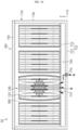
- FIG. 4 is a view for describing a venting mechanism during a thermal event of the battery pack 10 in FIG. 1 .
- an abnormal situation such as a thermal event may occur in at least one cell assembly 100 among the plurality of cell assemblies 100 of the battery pack 10.
- the thermal event may mean a thermal runaway situation due to overheating of at least one battery cell 110 of the cell assembly 100.
- thermal propagation to adjacent cell assemblies 100 causes a great risk that leads to serial ignition or further explosion of the entire battery pack 10, so it is important to prevent or delay this thermal propagation as much as possible.
- the partition member 300 partitions and covers adjacent cell assemblies 100 in the lateral direction (X-axis direction) of the battery pack 10, thermal propagation to adjacent cell assemblies 100 can be effectively prevented or slowed during thermal events of a specific cell assembly 100.
- the ejected matter G such as high-temperature gas or flame, escaping through the venting portion 115 of at least one battery cell 110 of the cell assembly 100 where the thermal event has occurred, may be ejected to the lower portion (-Z-axis direction) of the battery pack 10 through the bottom plate 212 of the case body 210 of the pack case 200.
- the bottom plate 212 is ruptured or melted at a predetermined temperature or pressure or above inside the pack case 200 during the thermal event so that the ejected matter G such as the high-temperature gas or flame can be emitted out of the pack case 200.
- the partition member 300 is provided in a structure that surrounds only both sides of the cell assemblies 100 so as not to interfere with the venting portion 115 of the battery cells 110 of the cell assemblies 100, so that the ejected matter G may be guided to be ejected faster and more rapidly.
- venting portions 115 of the battery cells 110 of the cell assemblies 100 are disposed to directly face the bottom plate 212 of the pack case 200, so the ejection path of the ejected matter G for the lower venting can be implemented with the shortest distance.
- FIG. 5 is a view for describing a battery pack 20 according to another embodiment of the present disclosure
- FIG. 6 is a view for describing a venting mechanism during a thermal event of the battery pack 20 of FIG. 5 .
- the battery pack 20 according to this embodiment is similar to the battery pack 10 of the previous embodiment, redundant description of the same or similar configurations as the previous embodiment will be omitted, and the following will focus on the differences from the previous embodiment.
- the battery pack 20 may include a plurality of cell assemblies 100, a pack case 200, a plurality of partition members 300, and a potting resin 400.
- the potting resin 400 may include silicone resin. Additionally, the potting resin 400 may include glass bubbles. The glass bubble may lower the specific gravity of the potting resin 400 and increase the energy density relative to weight.
- the potting resin 400 may be filled in the space between the plurality of cell assemblies 100 and the case cover 230 of the pack case 200.
- the potting resin 400 may be filled in the upper (+Z-axis direction) space of the plurality of cell assemblies 100 inside the pack case 200.
- the potting resin 400 is filled to cover the upper (+Z-axis direction) space of the cell assemblies 100 within the pack case 200, it is possible to effectively prevent the ejected matter G such as the high-temperature gas or flame from moving in the upper direction (+Z-axis direction) inside the pack case 200 or from entering the upper space inside the pack case 200 during the aforementioned thermal event.
- the potting resin 400 may be filled in the space between the plurality of cell assemblies 100.
- the potting resin 400 may also be filled between the partition members 300 surrounding the plurality of cell assemblies 100. Accordingly, when a thermal event or damage occurs due to an abnormal situation in at least one specific battery cell 110 among the plurality of cell assemblies 100, the potting resin 400 may prevent thermal propagation to adjacent cell assemblies 100 along with the partition member 300 and thus may effectively prevent additional thermal runaway due to heat transfer to adjacent cell assemblies 100.
- the potting resin 400 may also perform an insulating role to prevent electric connection to adjacent cell assemblies 100 in the event of a thermal event or damage in at least one specific battery cell 110 described above.
- the potting resin 400 may be continuously filled in the upper (+Z-axis direction) space of the cell assemblies 100, the space between the partition members 300 in the arrangement direction (X-axis direction) of the cell assemblies 100, and the inner wall space on both sides (X-axis direction) of the pack case 200, without any break or separation space.
- the potting resin 400 according to the embodiment of the present disclosure is continuously filled without interruption within the pack case 200, it is possible to realize even heat dispersion without causing heat dispersion deviation of the cell assemblies 100 and increase the cooling performance of the battery pack 20.
- the potting resin 400 may include materials with high specific heat performance. Accordingly, since the potting resin 400 increases the thermal mass and delays the temperature rise of the battery cells 110 even in situations such as rapid charging and discharging of the battery cells 110 of the cell assemblies 100, it is possible to prevent rapid temperature rise of the battery cells 110.
- the potting resin 400 may contain materials with high heat resistance. Accordingly, when a thermal event due to overheating or the like occurs in the battery cell 110 of at least one specific cell assembly 100 among the plurality of cell assemblies 100, the potting resin 400 may effectively prevent chain ignition or additional thermal runaway due to thermal propagation to adjacent cell assemblies 100.
- the potting resin 400 may include materials with high flame retardant performance. Accordingly, the potting resin 400 may minimize the risk of fire when a thermal event due to overheating or the like occurs in the battery cell 110 of at least one specific cell assembly 100 among the plurality of cell assemblies 100.
- the ejected matter G emitted from the venting portion 115 of the battery cell 110 during a thermal event is prevented from flowing in the upper direction (+Z-axis direction) inside the pack case 200 by means of the potting resin 400, it is possible to more reliably guide induced ejection of the ejected matter G for lower venting.
- FIG. 7 is a view for describing a battery pack 30 according to still another embodiment of the present disclosure.
- the battery pack 30 according to this embodiment is similar to the battery pack 10 of the previous embodiment, redundant description of the same or similar configurations as the previous embodiment will be omitted, and the following will focus on the differences from the previous embodiment.
- the battery pack 30 may include a plurality of cell assemblies 100, a plurality of partition members 300, and a pack case of 500.
- the pack case 500 may include a case body 510 and a case cover 530.
- the case cover 530 is similar to the previous embodiment, so the following will focus on the case body 510.
- the case body 510 may include a bottom plate 512 and a side plate 518.
- the side plate 518 is similar to the previous embodiment, so the following will focus on the bottom plate 512.
- An accommodation portion 514 may be formed on the bottom plate 512.
- the accommodation portion 514 may accommodate a part of the cell assemblies 100 and the partition members 300. Specifically, the accommodation portion 514 may accommodate the cell assemblies 100 surrounded by the partition members 300, respectively. More specifically, the lower end of each cell assembly 100 surrounded by the partition member 300 and the lower end of the partition member 300 may be inserted into the accommodation portion 514. Accordingly, the accommodation portion 514 may be formed to have a concave-convex shape along the arrangement direction (X-axis direction) of the cell assemblies 100 at the upper side (+Z-axis direction) of the inner surface of the bottom of the bottom plate 512.
- the accommodation portion 514 may include a seating portion 516 and a step portion 517.
- the lower ends of the cell assembly 100 and the partition member 300 may be accommodated in the seating portion 516.
- the step portion 517 may be provided at a predetermined height between the cell assemblies 100 surrounded by the partition members 300.
- the thickness of the seating portion 516 may be thinner than that of the step portion 517 and the side plate 518. This is to open the bottom plate 512 more quickly through easier rupture or melting during the thermal event because the seating portion 516 faces the venting portions 115 of the battery cells 110 of the cell assemblies 100.
- the seating portion 516 and the step portion 517 may be alternately arranged along the longitudinal direction (X-axis direction) of the bottom plate 512.
- one step portion 517 may be placed between two seating portions 516, and one seating portion 516 may be placed between two step portions 517.
- the step portions 517 may be disposed at both ends adjacent to the side plate 518 of the case body 510 of the pack case 500.
- the plurality of cell assemblies 100 and the partition members 300 may be more stably accommodated and supported within the pack case 200 by means of the accommodation portion 514 provided on the bottom plate 512 of the pack case 500.
- FIG. 8 is a view for describing a battery pack 40 according to still another embodiment of the present disclosure.
- the battery pack 40 according to this embodiment is similar to the battery pack 10 of the previous embodiment, redundant description of the same or similar configurations as the previous embodiment will be omitted, and the following will focus on the differences from the previous embodiment.
- the battery pack 40 may include a plurality of cell assemblies 100, a plurality of partition members 300, and a pack case 600.
- the pack case 600 may include a case body 610 and a case cover 630.
- the case cover 630 is similar to the previous embodiment, so the following will focus on the case body 610.
- the case body 610 may include a bottom plate 612 and a side plate 618.
- the side plate 618 is similar to the previous embodiment, so the following will focus on the bottom plate 612.
- a venting guide 615 may be formed on the bottom plate 612.
- the venting guide 615 may be ruptured or melted during the aforementioned thermal event to guide the ejected matter such as high-temperature gas or flame emitted from the venting portions 115 of the battery cells 110 to be discharged the lower side (-Z-axis direction) of the bottom plate 612.
- the venting guide 615 may be formed to have a predetermined depth from the outer surface of the bottom of the bottom plate 612 to have a relatively thin thickness at the bottom of the bottom plate 612.
- the venting guide 615 may be formed at positions corresponding to the bottoms of the venting portions 115 of the battery cells 110 of the plurality of cell assembly 100, respectively. Accordingly, unlike the bottom plate 512 of FIG.
- the bottom plate 612 may be formed in a structure with a convex-convex shape on the lower side (-Z-axis direction) of the outer surface of the bottom rather than the upper side (+Z-axis direction) of the inner surface of the bottom due to the venting guides 615 provided in a predetermined depth on the lower side (-Z-axis direction) of the outer surface of the bottom of the bottom plate 612.
- venting guide 615 is in contact with the venting portions 115 of the battery cells 110 and has a relatively thin thickness at the bottom of the bottom plate 612, it is possible to implement faster downward induced venting during the thermal event described above.
- the venting guide 615 through the venting guide 615, the discharge direction of the ejected matter during the thermal event can be more clearly guided to the lower direction (-Z-axis direction) of the pack case 600.
- FIG. 9 is a view for describing a battery pack 50 according to still another embodiment of the present disclosure
- FIG. 10 is a view for describing a venting mechanism during a thermal event of the battery pack 50 of FIG. 9 .
- the battery pack 50 according to this embodiment is similar to the battery pack 10 of the previous embodiment, redundant description of the same or similar configurations as the previous embodiment will be omitted, and the following will focus on the differences from the previous embodiment.
- the battery pack 50 may include a plurality of cell assemblies 100, a plurality of partition members 300, and a pack case 700.
- the pack case 700 may include a case body 710, a case cover 730, a guide channel 750, and a venting unit 770.
- the case body 710 may include a bottom plate 712 and a side plate 718.
- the side plate 718 is similar to the previous embodiment, so the following will focus on the bottom plate 712.
- the bottom plate 712 may include a first plate 713 and a second plate 715.
- the first plate 713 may support the plurality of cell assemblies 100 and the partition members 300.
- the first plate 713 may be placed to directly face the venting portions 115 of the plurality of battery cells 110, and may have a relatively thin thickness for easier rupture or melting during the thermal event described above.
- the first plate 713 may be prepared to have a thinner thickness than the second plate 715, which will be described later.
- the second plate 715 may be arranged to be spaced apart from the first plate 713 by a predetermined distance in the height direction (Z-axis direction) of the pack case 600. Accordingly, a predetermined space may be formed between the second plate 715 and the first plate 713. This predetermined space may function as a guide channel 750, which will be described later.
- the guide channel 750 may be formed in the space between the first plate 713 and the second plate 715.
- the guide channel 750 may guide the ejected matter G, such as high-temperature gas or flame, emitted through the venting portion 115 of the battery cells 110 and the first plate 713 during a thermal event of the cell assembly 100 toward the venting unit 770, which will be described later.
- the guide channel 750 may guide the ejected matter G, such as particles generated due to rupture or melting of the first plate 713 during the thermal event, toward the venting unit 770, which will be described later.
- the venting unit 770 is provided in the second plate 715, and may emit the ejected matter G, which is ruptured or melted during a thermal event and guided to the guide channel 750, out of the pack case 700.
- the venting unit 770 may also be provided with a structure that is opened or communicates the inside and the outside of the pack case 700 at a predetermined temperature or pressure or above.
- the venting structure of the venting unit 770 may be either a passive structure or an active structure capable of emitting the ejected matter G.
- the location of the venting unit 770 in the second plate 715 may correspond to the location of the fire extinguishing device or components for fire suppression outside the pack case 700.
- the venting unit 770 may be provided in plurality on the second plate 715.
- the ejected matter such as particles that may occur on the first plate 713 facing the battery cells 110 during the thermal event may also be effectively emitted to the outside of the pack case 700.
- the venting unit 770 provided in the second plate 715, the effect of induced ejection in a specific direction can be maximized when directional venting to the lower side.
- FIG. 11 is a view for describing a vehicle 1 according to an embodiment of the present disclosure.
- the vehicle 1 according to an embodiment of the present disclosure may include one or more battery packs 10, 20, 30, 40, 50 according to the present disclosure.
- the vehicle 1 according to an embodiment of the present disclosure may further include various other components included in the vehicle in addition to the battery packs 10, 20, 30, 40, 50.
- the vehicle 1 according to an embodiment of the present disclosure may further include a vehicle body, a motor, a control device such as ECU (electronic control unit), etc. in addition to the battery packs 10, 20, 30, 40, 50 according to an embodiment of the present disclosure.
- ECU electronic control unit
- the battery pack 10, 20, 30, 40, 50 may also be provided to other devices, instruments, and facilities, such as an energy storage system using a secondary battery, in addition to the vehicle 1.
- the vehicle 1 since the vehicle 1 according to an embodiment of the present disclosure includes the battery packs 10, 20, 30, 40, 50 of the previous embodiments, the vehicle 1 may also secure safety against the aforementioned thermal event.
- a battery pack 10, 20, 30, 40, 50 with improved safety against thermal events and a vehicle 1 including the battery pack.
- a battery pack 10, 20, 30, 40, 50 that can increase energy efficiency while slimming down the battery pack, and a vehicle 1 including the battery pack.
Landscapes
- Chemical & Material Sciences (AREA)
- Chemical Kinetics & Catalysis (AREA)
- Electrochemistry (AREA)
- General Chemical & Material Sciences (AREA)
- Engineering & Computer Science (AREA)
- Aviation & Aerospace Engineering (AREA)
- Life Sciences & Earth Sciences (AREA)
- Sustainable Development (AREA)
- Sustainable Energy (AREA)
- Power Engineering (AREA)
- Transportation (AREA)
- Mechanical Engineering (AREA)
- Manufacturing & Machinery (AREA)
- Battery Mounting, Suspending (AREA)
- Gas Exhaust Devices For Batteries (AREA)
Abstract
Description
- The present disclosure relates to a battery pack and a vehicle including the same, and more particularly, to a battery pack with improved safety against thermal events and a vehicle including the same.
- The present application claims priority to
Korean Patent Application No. 10-2022-0183383 filed on December 23, 2022 Korean Patent Application No. 10-2023-0043172 filed on March 31, 2023 - Secondary batteries have high applicability according to product groups and electrical characteristics such as high energy density, and thus, are commonly applied not only to mobile devices but also to electric vehicles (EVs) or hybrid vehicles (HEVs) driven by electric power sources. Because secondary batteries may radically reduce the use of fossil fuel and do not generate any by-products that come with energy consumption, the secondary batteries are gaining attention as a new alternative energy source for improving eco-friendliness and energy efficiency.
- Types of secondary batteries that are currently widely used include lithium-ion batteries, lithium polymer batteries, nickel cadmium batteries, nickel hydride batteries, and nickel zinc batteries. An operating voltage of a unit secondary battery cell, that is, a unit battery cell, ranges from about 2.5 V to about 4.5 V. Accordingly, when a higher output voltage is required, a battery pack may be configured by connecting a plurality of battery cells in series. Also, a battery pack may be configured by connecting a plurality of battery cells in parallel according to charge/discharge capacity required for the battery pack. Accordingly, the number of battery cells included in a battery pack may be set in various ways according to a required output voltage or charge/discharge capacity.
- When a battery pack is configured by connecting a plurality of battery cells in series/parallel, a method of first configuring a battery module including at least one battery cell and adding other elements by using the at least one battery module to configure a battery pack or battery rack is general.
- However, if a plurality of secondary batteries (battery cells) or a plurality of battery modules are crowded in a small space as above, they may be vulnerable to thermal events. In particular, if an event such as thermal runaway occurs in one battery cell, high-temperature gas or flame, heat, etc. may be generated. If such gas, flame, heat, etc. is transferred to other battery cells included in the same battery module, an explosive chain reaction situation such as thermal propagation may occur. Also, this chain reaction not only causes accidents such as fire or explosion in the relevant battery module, but can also cause fire or explosion in other battery modules.
- Moreover, in the case of middle- or large-sized battery packs for electric vehicles, etc., a large number of battery cells and battery modules are included to increase output and/or capacity, so the risk of thermal chain reaction may increase further. In addition, in the case of a battery pack mounted on an electric vehicle, etc., there may be users such as drivers nearby. Therefore, if a thermal event occurring in a specific battery module is not properly controlled and a chain reaction occurs, it may cause not only significant property damage but also loss of life.
- Therefore, if thermal runaway due to a thermal event occurs on a battery module basis within the battery pack, it is important that such high-temperature gas or flame and ejected matter, such as particles, escapes from the battery pack more quickly to prevent greater risks such as secondary ignition or explosion due to an increase in the internal pressure of the battery pack.
- However, within the battery pack, mechanisms for accommodating the battery module or structures for partitioning different battery modules within the battery pack are made of aluminum to ensure rigidity, and most of them are melt at about 600°C. During a thermal event, the particles generated due to the melting of these structures collapse the mechanisms of the battery modules or the structures used to partition different battery modules within the battery pack, or increase the internal pressure of the battery pack by blocking the discharge portion of the venting unit of the battery pack, which becomes an important factor that can cause greater damage, such as secondary ignition or explosion of the battery pack as described above.
- In addition, in the case of a conventional battery pack, there is a problem that the collapse of the aforementioned mechanism or the structures such as venting unit may be accelerated due to the influx of ejected matter such as high-temperature gas, flame, or particles generated during a thermal event into a gap space generated by assembly tolerances between the mechanisms of the battery modules described above or the components constituting the structures partitioning the battery modules.
- Therefore, there is a need to find a way to provide a battery pack and a vehicle including the same that can increase safety against thermal events while solving the above-mentioned problems.
- The present disclosure is designed to solve the problems of the related art, and therefore the present disclosure is directed to providing a battery pack with improved safety against thermal events and a vehicle including the battery pack.
- In addition, another object of the present disclosure is to provide a battery pack that can increase energy efficiency while slimming down the battery pack, and a vehicle including the battery pack.
- However, the technical problem to be solved by the present disclosure is not limited to the above-mentioned problem, and other problems not mentioned will be clearly understood by those skilled in the art from the present disclosure described below.
- In order to accomplish the above object, the present disclosure provides a battery pack, comprising a plurality of cell assemblies containing one or more battery cells and arranged in at least one row; a pack case configured to accommodate the plurality of cell assemblies; and a partition member configured to partition the plurality of cell assemblies within the pack case and made of flexible material to surround the plurality of cell assemblies in close contact.
- Also, preferably, the partition member may be in close contact with a side surface of the plurality of cell assemblies in an arrangement direction of the plurality of cell assemblies.
- Also, preferably, the partition member may be made of fire-resistant rubber material.
- Also, preferably, the partition member may be made of insulating rubber material.
- Also, preferably, the partition member may be placed between the plurality of cell assemblies in an arrangement direction of the plurality of cell assemblies.
- Also, preferably, the partition member may be provided in plurality corresponding to the number of the plurality of cell assemblies, and the plurality of partition members may be in close contact with both side surfaces of each cell assembly.
- Also, preferably, the plurality of partition members may be arranged to be spaced from each other by a predetermined distance in an arrangement direction of the plurality of cell assemblies.
- Also, preferably, a venting portion may be provided at a lower portion of the one or more battery cells, and the partition member may surround side surfaces of the plurality of cell assemblies while exposing the venting portion.
- Also, preferably, a bottom of the pack case may face the venting portion and be ruptured or melted, when gas or flame is discharged through the venting portion, to discharge the gas or flame out of the pack case.
- Also, preferably, the pack case may include a case body configured to support the plurality of cell assemblies and the partition member; and a case cover coupled with the case body to accommodate the plurality of cell assemblies and the partition member, and a bottom of the pack case may face the venting portion and be ruptured or melted, when gas or flame is discharged through the venting portion, to discharge the gas or flame out of the pack case.
- Also, preferably, a potting resin may be filled in the space between the plurality of cell assemblies and the case cover.
- Also, preferably, the potting resin may be filled in the space between the plurality of cell assemblies.
- Also, the present disclosure provides a vehicle comprising the battery pack according to the above embodiments.
- According to various embodiments as described above, it is possible to provide a battery pack with improved safety against thermal events and a vehicle including the battery pack.
- In addition, according to various embodiments as described above, it is possible to provide a battery pack that can increase energy efficiency while slimming down the battery pack, and a vehicle including the battery pack.
- In addition, the present disclosure may have various other effects, and these effects will be explained in each embodiment, or the explanation will be omitted for effects that can be easily inferred by a person skilled in the art.
- The accompanying drawings illustrate a preferred embodiment of the present disclosure and together with the foregoing disclosure, serve to provide further understanding of the technical features of the present disclosure, and thus, the present disclosure is not construed as being limited to the drawing.
-
FIG. 1 is a view for describing a battery pack according to an embodiment of the present disclosure. -
FIGS. 2 and3 are views to for describing a partition member surrounding a cell assembly of the battery pack ofFIG. 1 . -
FIG. 4 is a view for describing a venting mechanism during a thermal event of the battery pack inFIG. 1 . -
FIG. 5 is a view for describing a battery pack according to another embodiment of the present disclosure. -
FIG. 6 is a view for describing a venting mechanism during a thermal event of the battery pack ofFIG. 5 . -
FIG. 7 is a view for describing a battery pack according to still another embodiment of the present disclosure. -
FIG. 8 is a view for describing a battery pack according to still another embodiment of the present disclosure. -
FIG. 9 is a view for describing a battery pack according to still another embodiment of the present disclosure. -
FIG. 10 is a view for describing a venting mechanism during a thermal event of the battery pack ofFIG. 9 . -
FIG. 11 is a view for describing a vehicle according to an embodiment of the present disclosure. - Hereinafter, preferred embodiments of the present disclosure will be described in detail with reference to the accompanying drawings. Prior to the description, it should be understood that the terms used in the specification and the appended claims should not be construed as limited to general and dictionary meanings, but interpreted based on the meanings and concepts corresponding to technical aspects of the present disclosure on the basis of the principle that the inventor is allowed to define terms appropriately for the best explanation.
- Therefore, the description proposed herein is just a preferable example for the purpose of illustrations only, not intended to limit the scope of the disclosure, so it should be understood that other equivalents and modifications could be made thereto without departing from the scope of the disclosure.
- On the other hand, in the present disclosure, terms indicating directions such as up, down, left, right, front, and back are used, but these terms are only for convenience of explanation, it is obvious to those skilled in the art of the present disclosure that they may vary depending on the location of the target object or the location of the observer.
-
FIG. 1 is a view for describing abattery pack 10 according to an embodiment of the present disclosure, andFIGS. 2 and3 are views to for describing apartition member 300 surrounding acell assembly 100 of thebattery pack 10 ofFIG. 1 . - Referring to
FIGS. 1 to 3 , thebattery pack 10 may include acell assembly 100, apack case 200, and apartition member 300. - The
cell assembly 100 may include one ormore battery cells 110. In this embodiment, the description is limited to the fact that thecell assembly 100 includes a plurality ofbattery cells 110 in order to increase the output and/or capacity of thebattery pack 10. - The plurality of
battery cells 110 are secondary batteries and can be prepared as pouch-type secondary batteries. The plurality ofbattery cells 110 may be stacked so that they can be electrically connected to each other. Meanwhile, in this embodiment, the plurality ofbattery cells 110 are limited to being provided as pouch-type secondary batteries, but the cell assembly may also be prepared as a stack of cylindrical secondary batteries or prismatic secondary batteries other than the pouch-type secondary batteries. - The
cell assembly 100 may be provided in plurality and arranged in at least one row. The arrangement form of the plurality ofcell assemblies 100 may vary depending on the required capacity, size or shape of thebattery pack 10, and an arrangement of two or more rows or a matrix arrangement may be possible. Hereinafter, in an embodiment of the present disclosure, the plurality ofcell assemblies 100 are limited to being arranged in a row along the longitudinal direction (X-axis direction) of thebattery pack 10. - The
pack case 200 may accommodate the plurality ofcell assemblies 100. To this end, an accommodation space capable of accommodating the plurality ofcell assemblies 100 may be provided in thepack case 200. The specific structure of thepack case 200 will be discussed in more detail in the related description below. - The
partition member 300 may partition the plurality ofcell assemblies 100 within thepack case 200. Thepartition member 300 may support the plurality ofcell assemblies 100 while guiding the placement position of the plurality ofcell assemblies 100 within thepack case 200. - The
partition member 300 is made of flexible material and may surround the plurality ofcell assemblies 100 in close contact. Specifically, thepartition member 300 may be in close contact with the outside of the plurality ofcell assemblies 100 and surround the outside of the plurality ofcell assemblies 100. Thepartition member 300 as above may function as a housing for accommodating the plurality ofcell assemblies 100. - A structure such as a conventional module housing for accommodating the
cell assemblies 100 is made of metal, generally aluminum, unlike thepartition member 300, and is provided as a frame assembly with a considerable weight. Therefore, the conventional battery pack is generally configured to include a plurality of battery modules composed of these cell assemblies and a module housing for accommodating these cell assemblies. However, when the battery pack is composed of battery modules containing a plurality of cell assemblies, like a conventional battery pack, during a thermal event, the metal structure such as the module housing melts (approximately, at about 600°C), so a large amount of particles or the like are generated due to the melting of the structure in addition to high-temperature gas or flame. Excessive ejected matter, such as this large amount of particles, causes problems such as collapse of the mechanism that constitutes the battery module within the battery pack or the structure for partitioning the battery modules. - In addition, excessive ejected matter due to the large amount of particles mentioned above blocks the discharge part of the venting unit for expelling gas or flame to the outside of the battery pack, increasing the pressure inside the battery pack, which causes greater risks such as secondary ignition or explosion of the battery pack when a thermal event occurs.
- In addition, in the case of a frame assembly such as a conventional module housing, a gap space due to assembly tolerances cannot be avoided when assembling component parts or receiving the cell assembly. If ejected matter, such as high-temperature gas, flame, or particles, flows into this gap space during the aforementioned thermal event, it becomes more difficult to discharge the ejected matter, etc. from the inside of the battery pack, further accelerating the collapse of the battery pack mechanism.
- In an embodiment of the present disclosure, instead of a frame assembly such as a separate module housing for accommodating the
cell assemblies 100 as in the prior art, thepartition member 300 that surrounds the plurality ofcell assemblies 100 in close contact may be provided using a flexible material to accommodate and partition the plurality ofcell assemblies 100 within thepack case 200. - Therefore, in an embodiment of the present disclosure, through the
partition member 300 made of the flexible material, unlike the conventional module housing made of metal, during a thermal event, the amount of ejected matter such as particles that are melted and generated by a high-temperature gas or flame may be reduced, so the risk of collapse of the structure inside thebattery pack 10 or blocking of the venting path due to the ejected matter such as particles generated due to metal melting can be significantly lowered. As such, in an embodiment of the present disclosure, the risk of secondary damage that may occur when the thermal event occurs can be minimized through thepartition member 300. - Additionally, in an embodiment of the present disclosure, through the
partition member 300 in close contact with the plurality ofcell assemblies 100, a gap space is not created between the plurality ofcell assemblies 100 and thepartition member 300, so problems such as accumulation or stagnation of ejected matter such as high-temperature gas, flame, or particles that can occur within the gap space during a thermal event can be fundamentally prevented. - In addition, in an embodiment of the present disclosure, through the
partition member 300, a frame assembly such as a separate module housing made of metal, which has a considerable weight as in the past, can be omitted, thereby realizing slimming of theentire battery pack 10 and significantly increasing the energy efficiency while reducing weight. In other words, in the present disclosure, it is possible to configure abattery pack 10 of so-called CTP (Cell To Pack) type, which configuresbattery pack 10 while omitting the module housing, through thepartition member 300. - In addition, in an embodiment of the present disclosure, the
partition member 300 is made of a flexible material, so of course, easier assembly can be secured when accommodating thecell assemblies 100. - Below, the
partition member 300 according to an embodiment of the present disclosure will be explained in more detail. - The
partition member 300 may be in close contact with the side surface of the plurality ofcell assemblies 100 in the arrangement direction (X-axis direction) of the plurality ofcell assemblies 100. In the case of pouch-type secondary batteries, cell expansion, called cell swelling, generally occurs during overheating or continued charging and discharging, and this cell swelling has the greatest amount of deformation on the side surface of thebattery cell 110. - In an embodiment of the present disclosure, since the
partition member 300 is in close contact with the side surface of the plurality ofcell assembly 100, cell expansion of thecell assembly 100 can be effectively controlled during cell swelling. - The
partition member 300 may surround only the side surfaces of the plurality ofcell assemblies 100 in close contact. That is, thepartition member 300 may have an accommodation space therein to accommodate thecell assemblies 100 and may have an opening that exposes the upper and lower sides of thecell assemblies 100 in the upper and lower directions (Z-axis direction). To this end, thepartition member 300 may be provided as a hollow structure with openings exposed in the upper and lower directions (Z-axis direction). Thecell assemblies 100 may be inserted to be placed in the accommodation space inside thepartition member 300 through the openings in the upper and lower directions (Z-axis direction) of thepartition member 300. - Therefore, in this embodiment, work convenience for workers or the like can be increased during the assembly process between the
cell assemblies 100 and thepartition member 300. Additionally, in this embodiment, since thepartition member 300 does not cover the upper and lower sides of the plurality ofcell assemblies 100 in the upper and lower directions (Z-axis direction) of thecell assembly 100, the size of theentire battery pack 10 may be further slimmed in the upper and lower directions (Z-axis direction) of thebattery pack 10. - In the opening exposed at the lower side of the
partition member 300, the bottom of the plurality ofbattery cells 110 of the plurality ofcell assemblies 100 may be in contact with thebottom plate 212 of thecase body 210 of thepack case 200, which will be described later, or may be arranged to be spaced apart by a predetermined interval. Meanwhile, a ventingportion 115 may be provided at the bottom of thebattery cells 110 of the plurality ofcell assemblies 100 to discharge internal gas or the like during a thermal event, which will be described in more detail in the related description below. In this way, thepartition member 300 according to this embodiment can solve the problem of interference with the ventingportion 115 of the plurality ofbattery cells 110 through the opening structure exposed in the upper and lower directions (Z-axis direction). - The
partition member 300 may be made of fire-resistant rubber material. For example, thepartition member 300 may be made of a flexible fire-resistant rubber material that can maintain its shape for at least 5 minutes when heated at approximately 1300°C to ensure fire resistance. - In an embodiment of the present disclosure, through the
partition member 300 made of a fire-resistant rubber material, it is possible to withstand high-temperature gas or flame without changing the shape for a considerable period of time during a thermal event, so that the speed of thermal propagation to acell assembly 100 adjacent to thecell assembly 100 in which the thermal event occurs can be delayed as much as possible, and the risk of occurrence of ejected matter such as a large amount of particles due to melting can be significantly reduced. - The
partition member 300 may be made of an insulating rubber material. In an embodiment of the present disclosure, insulation performance can also be secured through thepartition member 300 made of this insulating material, so that even if an electrical problem occurs in any onecell assembly 100, it is possible to effectively prevent short circuits or the like, which may be chained to theadjacent cell assemblies 100. - The
partition member 300 may be arranged between the plurality ofcell assemblies 100 in the arrangement direction (X-axis direction) of the plurality ofcell assemblies 100. Through this arrangement structure of thepartition member 300, the plurality ofcell assemblies 100 may be partitioned, respectively, within thepack case 200, so that thermal propagation toadjacent cell assemblies 100 can be effectively delayed when a thermal event or the like occurs. - The
partition member 300 may be provided in plurality corresponding to the number of the plurality ofcell assemblies 100. The plurality ofpartition members 300 may be in close contact with both side surfaces of eachcell assembly 100. Here, each of the plurality ofpartition members 300 may accommodate onecell assembly 100. That is, eachpartition member 300 may accommodate eachcell assembly 100 and surround both sides of eachcell assembly 100 in close contact. - In an embodiment of the present disclosure, the
partition member 300 is provided in plurality to correspond to the number of thecell assemblies 100, and eachpartition member 300 accommodates thecell assembly 100, so the plurality ofcell assemblies 100 can be supported more stably, and the plurality ofcell assemblies 100 can be partitioned and placed separately more clearly within thepack case 200. - The plurality of
partition members 300 may be provided as a hollow structure with the opening exposed in the upper and lower directions (Z-axis direction) while having an accommodation space therein to accommodate eachcell assembly 100. Regarding the accommodation space, as an example, onepartition member 300 and thecell assembly 100 accommodated within onepartition member 300 are as follows. The accommodation width (W1) of the accommodation space of thepartition member 300 may be provided to be equal to or smaller than the entire width (W2) of thecell assembly 100. This is to further increase the adhesion performance to both sides of thecell assembly 100 through thepartition member 300 of the flexible material. More preferably, in an embodiment of the present disclosure, the accommodation width (W1) of the accommodation space of thepartition member 300 may be formed to be smaller than the entire width (W2) of thecell assembly 100 to further increase the adhesion performance. - The plurality of
partition members 300 may be arranged to be spaced apart from each other by a predetermined distance in the arrangement direction (X-axis direction) of the plurality ofcell assemblies 100. Specifically, the plurality ofpartition members 300 may make the plurality ofcell assemblies 100 be spaced apart from each other by a predetermined interval within thepack case 200. - Through this spaced arrangement structure, when a thermal event such as thermal runaway occurs in any one
cell assembly 100, since thecell assembly 100 in which an abnormal situation has occurred is spaced apart fromadjacent cell assemblies 100 by not onlypartition members 300 but also the space required for the spaced arrangement, the risk of thermal propagation can be minimized or delayed as much as possible. - The separation structure of the plurality of
partition members 300 will be described in more detail as follows. Thepartition members 300 facing each other in the arrangement direction (X-axis direction) are arranged to have a first interval (d1), and thepartition members 300 facing the inner wall of thepack case 200 in the arrangement direction (X-axis direction) may be arranged to have a second interval (d2). The first interval (d1) can be designed considering the cell expansion width in both lateral directions (X-axis direction) of the twocell assemblies 100 arranged opposite each other. Also, the second interval (d2) faces the inner wall of thepack case 200, and thus can be designed considering the cell expansion width in the lateral direction (X-axis direction) of onecell assembly 100. Therefore, the first interval (d1) may be formed to be larger than the second interval (d2). Preferably, the first interval (d1) may be provided to be approximately at least twice the size of the second interval (d2). - Below, one or
more battery cells 110 of the plurality ofcell assemblies 100 will be described in more detail. - The one or
more battery cells 110, as described above, are provided as pouch-type secondary batteries, and may be configured to include an electrode assembly, a pair of electrode leads electrically connected to the electrode assembly, and a battery case that exposes a part of the pair of electrode leads and accommodates the electrode assembly, respectively. - A venting
portion 115 may be provided at the lower part (-Z-axis direction) of the plurality ofbattery cells 110. The ventingportion 115 may be ruptured or melted at a predetermined temperature or pressure or above to allow gas or flame inside thebattery cell 110 to be ejected in abnormal situations such as overheating, thereby guiding the ejecting matter such as gas or flame inside thebattery cell 110 to be discharged to the outside of thebattery cell 110. - The
partition member 300 may surround the side surface of the plurality ofcell assemblies 100 while exposing the ventingportion 115. Since thepartition member 300 exposes the ventingportion 115, it does not cause interference with the ventingportion 115 and thus may guide the smooth discharge of the ejected matter such as gas or flame through the ventingportion 115. - Below, the
pack case 200 according to an embodiment of the present disclosure will be described in more detail. - The
bottom 212 of thepack case 200 faces the ventingportion 115, and when ejected matter such as gas or flame is discharged through the ventingportion 115, the bottom 212 may be ruptured or melted so that the gas or flame may be emitted out of thepack case 200. - In an embodiment of the present disclosure, since the
bottom 212 of thepack case 200 is placed to face the ventingportion 115, the ejected matter discharge path through the ventingportion 115 is simplified, so the ejected matter can be emitted out of thepack case 200 more rapidly in abnormal situations such as thermal events. That is, in an embodiment of the present disclosure, thebottom 212 of thepack case 200 is arranged to face the ventingportion 115, thereby inducing venting in the lower direction (-Z-axis direction) of thebattery pack 10. - Therefore, the
battery pack 10 according to an embodiment of the present disclosure induces bottom venting in the shortest path as directional venting, so that the ejected matter such as high-temperature gas or flame caused by the occurrence of the thermal event can be emitted out of thepack case 200 more rapidly. - The
pack case 200 may include acase body 210 and acase cover 230. - The
case body 210 may support the plurality ofcell assemblies 100 and thepartition member 300. Additionally, thecase body 210 may have a forward accommodation space that may accommodate the plurality ofcell assemblies 100 and thepartition member 300. - The
case cover 230 may be coupled with thecase body 210 and accommodate the plurality ofcell assemblies 100 and thepartition member 300. Specifically, thecase cover 230 may be coupled to thecase body 210 by being coupled to theside plate 518 of thecase body 210, which will be described later, through bolting or bonding. Of course, the coupling structure such as the bolting coupling or the bonding coupling is only an example, and other coupling structures for stably coupling thecase cover 230 and thecase body 210 to each other may also be possible. - The
bottom 212 of thecase body 210 faces the ventingportion 115, and may be ruptured or melted to discharge the ejected matter, such as gas or flame, out of thepack case 200 when the ejected matter, such as gas or flame, is discharged through the ventingportion 115. Thebottom 212 of thecase body 210 may have a relatively thin thickness in thecase body 210 for easier rupture or melting. - Below, the
case body 210 will be described in more detail. - The
case body 210 may include abottom plate 212 and aside plate 218. - The
bottom plate 212 supports the plurality ofcell assemblies 100 and the plurality ofpartition members 300, and may be disposed to face the ventingportions 115 of thebattery cells 110 of the plurality ofcell assemblies 100. - The
bottom plate 212 may open the inside of thepack case 200 by rupturing or melting at a certain temperature or pressure or above so that the ejected matter such as high-temperature gas or flame inside thepack case 200 can be ejected during the thermal event. Thebottom plate 212 may be formed to have a thinner thickness than theside plate 218 for easier rupture or melting. - Meanwhile, the
bottom plate 212 may include a venting unit that melts or ruptures at the above-mentioned temperature or pressure as a separate member. - Therefore, the
bottom plate 212 itself may function as a venting unit, or a separate venting unit is provided on thebottom plate 212, so that directional venting for lower venting to the bottom of thepack case 200 during the thermal event can be implemented. - The
side plate 218 is formed integrally with thebottom plate 212 and may extend vertically from both sides of thebottom plate 212. Meanwhile, theside plate 218 may be provided as a separate member from thebottom plate 212 and may be coupled with thebottom plate 212 through bolting or bonding to form thecase body 210. Theside plate 218 is coupled with thecase cover 230 and may form the side exterior of thepack case 200. - Below, the venting mechanism for expelling high-temperature gas or flame inside the
pack case 200 in abnormal situations such as a thermal event of thebattery pack 10 according to an embodiment of the present disclosure will be described in more detail. -
FIG. 4 is a view for describing a venting mechanism during a thermal event of thebattery pack 10 inFIG. 1 . - Referring to
FIG. 4 , an abnormal situation such as a thermal event may occur in at least onecell assembly 100 among the plurality ofcell assemblies 100 of thebattery pack 10. The thermal event may mean a thermal runaway situation due to overheating of at least onebattery cell 110 of thecell assembly 100. - When a thermal runaway situation occurs in a
specific cell assembly 100 within thepack case 200, thermal propagation toadjacent cell assemblies 100 causes a great risk that leads to serial ignition or further explosion of theentire battery pack 10, so it is important to prevent or delay this thermal propagation as much as possible. - In an embodiment of the present disclosure, as described above, since the
partition member 300 partitions and coversadjacent cell assemblies 100 in the lateral direction (X-axis direction) of thebattery pack 10, thermal propagation toadjacent cell assemblies 100 can be effectively prevented or slowed during thermal events of aspecific cell assembly 100. - Meanwhile, in the case of the thermal event, the ejected matter G, such as high-temperature gas or flame, escaping through the venting
portion 115 of at least onebattery cell 110 of thecell assembly 100 where the thermal event has occurred, may be ejected to the lower portion (-Z-axis direction) of thebattery pack 10 through thebottom plate 212 of thecase body 210 of thepack case 200. Thebottom plate 212 is ruptured or melted at a predetermined temperature or pressure or above inside thepack case 200 during the thermal event so that the ejected matter G such as the high-temperature gas or flame can be emitted out of thepack case 200. - In an embodiment of the present disclosure, the
partition member 300 is provided in a structure that surrounds only both sides of thecell assemblies 100 so as not to interfere with the ventingportion 115 of thebattery cells 110 of thecell assemblies 100, so that the ejected matter G may be guided to be ejected faster and more rapidly. - Additionally, in an embodiment of the present disclosure, the venting
portions 115 of thebattery cells 110 of thecell assemblies 100 are disposed to directly face thebottom plate 212 of thepack case 200, so the ejection path of the ejected matter G for the lower venting can be implemented with the shortest distance. -
FIG. 5 is a view for describing abattery pack 20 according to another embodiment of the present disclosure, andFIG. 6 is a view for describing a venting mechanism during a thermal event of thebattery pack 20 ofFIG. 5 . - Since the
battery pack 20 according to this embodiment is similar to thebattery pack 10 of the previous embodiment, redundant description of the same or similar configurations as the previous embodiment will be omitted, and the following will focus on the differences from the previous embodiment. - Referring to
FIGS. 5 and6 , thebattery pack 20 may include a plurality ofcell assemblies 100, apack case 200, a plurality ofpartition members 300, and apotting resin 400. - Since the plurality of
cell assemblies 100, thepack case 200, and the plurality ofpartition members 300 are substantially the same or similar to the previous embodiment, redundant description will be omitted below. - The
potting resin 400 may include silicone resin. Additionally, thepotting resin 400 may include glass bubbles. The glass bubble may lower the specific gravity of thepotting resin 400 and increase the energy density relative to weight. - The
potting resin 400 may be filled in the space between the plurality ofcell assemblies 100 and thecase cover 230 of thepack case 200. In other words, thepotting resin 400 may be filled in the upper (+Z-axis direction) space of the plurality ofcell assemblies 100 inside thepack case 200. In this way, since thepotting resin 400 is filled to cover the upper (+Z-axis direction) space of thecell assemblies 100 within thepack case 200, it is possible to effectively prevent the ejected matter G such as the high-temperature gas or flame from moving in the upper direction (+Z-axis direction) inside thepack case 200 or from entering the upper space inside thepack case 200 during the aforementioned thermal event. - Additionally, the
potting resin 400 may be filled in the space between the plurality ofcell assemblies 100. In other words, thepotting resin 400 may also be filled between thepartition members 300 surrounding the plurality ofcell assemblies 100. Accordingly, when a thermal event or damage occurs due to an abnormal situation in at least onespecific battery cell 110 among the plurality ofcell assemblies 100, thepotting resin 400 may prevent thermal propagation toadjacent cell assemblies 100 along with thepartition member 300 and thus may effectively prevent additional thermal runaway due to heat transfer toadjacent cell assemblies 100. In addition, thepotting resin 400 may also perform an insulating role to prevent electric connection toadjacent cell assemblies 100 in the event of a thermal event or damage in at least onespecific battery cell 110 described above. - Within the
pack case 200, thepotting resin 400 may be continuously filled in the upper (+Z-axis direction) space of thecell assemblies 100, the space between thepartition members 300 in the arrangement direction (X-axis direction) of thecell assemblies 100, and the inner wall space on both sides (X-axis direction) of thepack case 200, without any break or separation space. In this way, since thepotting resin 400 according to the embodiment of the present disclosure is continuously filled without interruption within thepack case 200, it is possible to realize even heat dispersion without causing heat dispersion deviation of thecell assemblies 100 and increase the cooling performance of thebattery pack 20. - The
potting resin 400 may include materials with high specific heat performance. Accordingly, since thepotting resin 400 increases the thermal mass and delays the temperature rise of thebattery cells 110 even in situations such as rapid charging and discharging of thebattery cells 110 of thecell assemblies 100, it is possible to prevent rapid temperature rise of thebattery cells 110. - The
potting resin 400 may contain materials with high heat resistance. Accordingly, when a thermal event due to overheating or the like occurs in thebattery cell 110 of at least onespecific cell assembly 100 among the plurality ofcell assemblies 100, thepotting resin 400 may effectively prevent chain ignition or additional thermal runaway due to thermal propagation toadjacent cell assemblies 100. - The
potting resin 400 may include materials with high flame retardant performance. Accordingly, thepotting resin 400 may minimize the risk of fire when a thermal event due to overheating or the like occurs in thebattery cell 110 of at least onespecific cell assembly 100 among the plurality ofcell assemblies 100. - As described above, in the
battery pack 20 according to an embodiment of the present disclosure, since the ejected matter G emitted from the ventingportion 115 of thebattery cell 110 during a thermal event is prevented from flowing in the upper direction (+Z-axis direction) inside thepack case 200 by means of thepotting resin 400, it is possible to more reliably guide induced ejection of the ejected matter G for lower venting. -
FIG. 7 is a view for describing abattery pack 30 according to still another embodiment of the present disclosure. - Since the
battery pack 30 according to this embodiment is similar to thebattery pack 10 of the previous embodiment, redundant description of the same or similar configurations as the previous embodiment will be omitted, and the following will focus on the differences from the previous embodiment. - Referring to
FIG. 7 , thebattery pack 30 may include a plurality ofcell assemblies 100, a plurality ofpartition members 300, and a pack case of 500. - Since the plurality of
cell assemblies 100 and the plurality ofpartition members 300 are substantially the same or similar to the previous embodiment, redundant description will be omitted below. - The
pack case 500 may include acase body 510 and acase cover 530. In this embodiment, thecase cover 530 is similar to the previous embodiment, so the following will focus on thecase body 510. - The
case body 510 may include abottom plate 512 and aside plate 518. In this embodiment, theside plate 518 is similar to the previous embodiment, so the following will focus on thebottom plate 512. - An
accommodation portion 514 may be formed on thebottom plate 512. - The
accommodation portion 514 may accommodate a part of thecell assemblies 100 and thepartition members 300. Specifically, theaccommodation portion 514 may accommodate thecell assemblies 100 surrounded by thepartition members 300, respectively. More specifically, the lower end of eachcell assembly 100 surrounded by thepartition member 300 and the lower end of thepartition member 300 may be inserted into theaccommodation portion 514. Accordingly, theaccommodation portion 514 may be formed to have a concave-convex shape along the arrangement direction (X-axis direction) of thecell assemblies 100 at the upper side (+Z-axis direction) of the inner surface of the bottom of thebottom plate 512. - The
accommodation portion 514 may include aseating portion 516 and astep portion 517. The lower ends of thecell assembly 100 and thepartition member 300 may be accommodated in theseating portion 516. Thestep portion 517 may be provided at a predetermined height between thecell assemblies 100 surrounded by thepartition members 300. Meanwhile, the thickness of theseating portion 516 may be thinner than that of thestep portion 517 and theside plate 518. This is to open thebottom plate 512 more quickly through easier rupture or melting during the thermal event because theseating portion 516 faces the ventingportions 115 of thebattery cells 110 of thecell assemblies 100. - The
seating portion 516 and thestep portion 517 may be alternately arranged along the longitudinal direction (X-axis direction) of thebottom plate 512. In other words, in the longitudinal direction (X-axis direction) of thebottom plate 512, onestep portion 517 may be placed between two seatingportions 516, and oneseating portion 516 may be placed between twostep portions 517. However, in thebottom plate 512, thestep portions 517 may be disposed at both ends adjacent to theside plate 518 of thecase body 510 of thepack case 500. - In the
battery pack 30 according to this embodiment, the plurality ofcell assemblies 100 and thepartition members 300 may be more stably accommodated and supported within thepack case 200 by means of theaccommodation portion 514 provided on thebottom plate 512 of thepack case 500. -
FIG. 8 is a view for describing abattery pack 40 according to still another embodiment of the present disclosure. - Since the
battery pack 40 according to this embodiment is similar to thebattery pack 10 of the previous embodiment, redundant description of the same or similar configurations as the previous embodiment will be omitted, and the following will focus on the differences from the previous embodiment. - Referring to
FIG. 8 , thebattery pack 40 may include a plurality ofcell assemblies 100, a plurality ofpartition members 300, and apack case 600. - Since the plurality of
cell assemblies 100 and the plurality ofpartition members 300 are substantially the same or similar to the previous embodiment, redundant description will be omitted below. - The
pack case 600 may include acase body 610 and acase cover 630. In this embodiment, thecase cover 630 is similar to the previous embodiment, so the following will focus on thecase body 610. - The
case body 610 may include abottom plate 612 and aside plate 618. In this embodiment, theside plate 618 is similar to the previous embodiment, so the following will focus on thebottom plate 612. - A venting
guide 615 may be formed on thebottom plate 612. - The venting
guide 615 may be ruptured or melted during the aforementioned thermal event to guide the ejected matter such as high-temperature gas or flame emitted from the ventingportions 115 of thebattery cells 110 to be discharged the lower side (-Z-axis direction) of thebottom plate 612. - The venting
guide 615 may be formed to have a predetermined depth from the outer surface of the bottom of thebottom plate 612 to have a relatively thin thickness at the bottom of thebottom plate 612. In addition, the ventingguide 615 may be formed at positions corresponding to the bottoms of the ventingportions 115 of thebattery cells 110 of the plurality ofcell assembly 100, respectively. Accordingly, unlike thebottom plate 512 ofFIG. 7 , thebottom plate 612 may be formed in a structure with a convex-convex shape on the lower side (-Z-axis direction) of the outer surface of the bottom rather than the upper side (+Z-axis direction) of the inner surface of the bottom due to the venting guides 615 provided in a predetermined depth on the lower side (-Z-axis direction) of the outer surface of the bottom of thebottom plate 612. - In this embodiment, since the venting
guide 615 is in contact with the ventingportions 115 of thebattery cells 110 and has a relatively thin thickness at the bottom of thebottom plate 612, it is possible to implement faster downward induced venting during the thermal event described above. - Additionally, in the embodiment of the present disclosure, on the lower side (-Z-axis direction) of the outer surface of the bottom of the
bottom plate 612, since the portion of thebottom plate 612 between the venting guides 615 is formed in a structure that protrudes further toward the lower portion (-Z-axis direction), it is possible to effectively prevent the ejected matter emitted out of aspecific venting guide 615 or particles generated due to rupture or melting of aspecific venting guide 615 from being dispersed toward adjacent venting guides 615. That is, in an embodiment of the present disclosure, through the convex-convex structure on the lower side (-Z-axis direction) of the outer surface of thebottom plate 612 provided by the ventingguide 615, when the ejected matter is induced to be ejected downward, it is possible to effectively prevent the ejected matter from being dispersed in the left and right directions (X-axis direction) of thebottom plate 612. - Therefore, in an embodiment of the present disclosure, through the venting
guide 615, the discharge direction of the ejected matter during the thermal event can be more clearly guided to the lower direction (-Z-axis direction) of thepack case 600. -
FIG. 9 is a view for describing abattery pack 50 according to still another embodiment of the present disclosure, andFIG. 10 is a view for describing a venting mechanism during a thermal event of thebattery pack 50 ofFIG. 9 . - Since the
battery pack 50 according to this embodiment is similar to thebattery pack 10 of the previous embodiment, redundant description of the same or similar configurations as the previous embodiment will be omitted, and the following will focus on the differences from the previous embodiment. - Referring to
FIGS. 9 and10 , thebattery pack 50 may include a plurality ofcell assemblies 100, a plurality ofpartition members 300, and apack case 700. - Since the plurality of
cell assemblies 100 and the plurality ofpartition members 300 are substantially the same or similar to the previous embodiment, redundant description will be omitted below. - The
pack case 700 may include acase body 710, acase cover 730, aguide channel 750, and aventing unit 770. - The
case body 710 may include abottom plate 712 and aside plate 718. In this embodiment, theside plate 718 is similar to the previous embodiment, so the following will focus on thebottom plate 712. - The
bottom plate 712 may include afirst plate 713 and asecond plate 715. - The
first plate 713 may support the plurality ofcell assemblies 100 and thepartition members 300. Thefirst plate 713 may be placed to directly face the ventingportions 115 of the plurality ofbattery cells 110, and may have a relatively thin thickness for easier rupture or melting during the thermal event described above. For example, thefirst plate 713 may be prepared to have a thinner thickness than thesecond plate 715, which will be described later. - The
second plate 715 may be arranged to be spaced apart from thefirst plate 713 by a predetermined distance in the height direction (Z-axis direction) of thepack case 600. Accordingly, a predetermined space may be formed between thesecond plate 715 and thefirst plate 713. This predetermined space may function as aguide channel 750, which will be described later. - Since the
case cover 730 is substantially the same or similar to the previous embodiment, redundant description will be omitted below. - The
guide channel 750 may be formed in the space between thefirst plate 713 and thesecond plate 715. Theguide channel 750 may guide the ejected matter G, such as high-temperature gas or flame, emitted through the ventingportion 115 of thebattery cells 110 and thefirst plate 713 during a thermal event of thecell assembly 100 toward theventing unit 770, which will be described later. Theguide channel 750 may guide the ejected matter G, such as particles generated due to rupture or melting of thefirst plate 713 during the thermal event, toward theventing unit 770, which will be described later. - The
venting unit 770 is provided in thesecond plate 715, and may emit the ejected matter G, which is ruptured or melted during a thermal event and guided to theguide channel 750, out of thepack case 700. In addition to the structure that ruptures or melts at a predetermined temperature or pressure or above, theventing unit 770 may also be provided with a structure that is opened or communicates the inside and the outside of thepack case 700 at a predetermined temperature or pressure or above. Ultimately, the venting structure of theventing unit 770 may be either a passive structure or an active structure capable of emitting the ejected matter G. Meanwhile, the location of theventing unit 770 in thesecond plate 715 may correspond to the location of the fire extinguishing device or components for fire suppression outside thepack case 700. In addition, of course, theventing unit 770 may be provided in plurality on thesecond plate 715. - In the
battery pack 50 according to an embodiment of the present disclosure, through thebottom plate 712 composed of the first andsecond plates guide channel 750, the ejected matter such as particles that may occur on thefirst plate 713 facing thebattery cells 110 during the thermal event may also be effectively emitted to the outside of thepack case 700. - In addition, in the
battery pack 50 according to an embodiment of the present disclosure, through theventing unit 770 provided in thesecond plate 715, the effect of induced ejection in a specific direction can be maximized when directional venting to the lower side. -
FIG. 11 is a view for describing a vehicle 1 according to an embodiment of the present disclosure. - Referring to
FIG. 11 , the vehicle 1 according to an embodiment of the present disclosure may include one or more battery packs 10, 20, 30, 40, 50 according to the present disclosure. In addition, the vehicle 1 according to an embodiment of the present disclosure may further include various other components included in the vehicle in addition to the battery packs 10, 20, 30, 40, 50. For example, the vehicle 1 according to an embodiment of the present disclosure may further include a vehicle body, a motor, a control device such as ECU (electronic control unit), etc. in addition to the battery packs 10, 20, 30, 40, 50 according to an embodiment of the present disclosure. - In addition, the
battery pack - As described above, since the vehicle 1 according to an embodiment of the present disclosure includes the battery packs 10, 20, 30, 40, 50 of the previous embodiments, the vehicle 1 may also secure safety against the aforementioned thermal event.
- According to various embodiments as described above, it is possible to provide a
battery pack - In addition, according to various embodiments as described above, it is possible to provide a
battery pack - While the preferred embodiments of the present disclosure have been shown and described, the present disclosure is not limited to the specific embodiments described above, various modifications may be made by one of ordinary skill in the art to which the present disclosure pertains without departing from the gist of the present disclosure as defined by the claims, and these modifications should not be individually understood from the technical feature or prospect of the present disclosure.
Claims (13)
- A battery pack, comprising:a plurality of cell assemblies containing one or more battery cells and arranged in at least one row;a pack case configured to accommodate the plurality of cell assemblies; anda partition member configured to partition the plurality of cell assemblies within the pack case and made of flexible material to surround the plurality of cell assemblies in close contact.
- The battery pack according to claim 1, wherein the partition member is in close contact with a side surface of the plurality of cell assemblies in an arrangement direction of the plurality of cell assemblies.
- The battery pack according to claim 1, wherein the partition member is made of fire-resistant rubber material.
- The battery pack according to claim 1, wherein the partition member is made of insulating rubber material.
- The battery pack according to claim 1, wherein the partition member is placed between the plurality of cell assemblies in an arrangement direction of the plurality of cell assemblies.
- The battery pack according to claim 1, wherein the partition member is provided in plurality corresponding to the number of the plurality of cell assemblies, and
wherein the plurality of partition members are in close contact with both side surfaces of each cell assembly. - The battery pack according to claim 6, wherein the plurality of partition members are arranged to be spaced from each other by a predetermined distance in an arrangement direction of the plurality of cell assemblies.
- The battery pack according to claim 1, wherein a venting portion is provided at a lower portion of the one or more battery cells, and
wherein the partition member surrounds side surfaces of the plurality of cell assemblies while exposing the venting portion. - The battery pack according to claim 8, wherein a bottom of the pack case faces the venting portion and is ruptured or melted, when gas or flame is discharged through the venting portion, to discharge the gas or flame out of the pack case.
- The battery pack according to claim 8, wherein the pack case includes:a case body configured to support the plurality of cell assemblies and the partition member; anda case cover coupled with the case body to accommodate the plurality of cell assemblies and the partition member, andwherein a bottom of the pack case faces the venting portion and is ruptured or melted, when gas or flame is discharged through the venting portion, to discharge the gas or flame out of the pack case.
- The battery pack according to claim 10, wherein a potting resin is filled in the space between the plurality of cell assemblies and the case cover.
- The battery pack according to claim 11, wherein the potting resin is filled in the space between the plurality of cell assemblies.
- A vehicle comprising the battery pack according to any one of claims 1 to 12.
Priority Applications (1)
| Application Number | Priority Date | Filing Date | Title |
|---|---|---|---|
| EP26168073.0A EP4742398A2 (en) | 2022-12-23 | 2023-07-07 | Battery pack and vehicle including the same |
Applications Claiming Priority (3)
| Application Number | Priority Date | Filing Date | Title |
|---|---|---|---|
| KR20220183383 | 2022-12-23 | ||
| KR1020230043172A KR20240101296A (en) | 2022-12-23 | 2023-03-31 | Battery pack and vehicle comprising the battery pack |
| PCT/KR2023/009704 WO2024135970A1 (en) | 2022-12-23 | 2023-07-07 | Battery pack and vehicle comprising same |
Related Child Applications (1)
| Application Number | Title | Priority Date | Filing Date |
|---|---|---|---|
| EP26168073.0A Division EP4742398A2 (en) | 2022-12-23 | 2023-07-07 | Battery pack and vehicle including the same |
Publications (2)
| Publication Number | Publication Date |
|---|---|
| EP4462553A1 true EP4462553A1 (en) | 2024-11-13 |
| EP4462553A4 EP4462553A4 (en) | 2025-08-13 |
Family
ID=91589144
Family Applications (2)
| Application Number | Title | Priority Date | Filing Date |
|---|---|---|---|
| EP23907262.2A Pending EP4462553A4 (en) | 2022-12-23 | 2023-07-07 | BATTERY PACK AND VEHICLE WITH IT |
| EP26168073.0A Pending EP4742398A2 (en) | 2022-12-23 | 2023-07-07 | Battery pack and vehicle including the same |
Family Applications After (1)
| Application Number | Title | Priority Date | Filing Date |
|---|---|---|---|
| EP26168073.0A Pending EP4742398A2 (en) | 2022-12-23 | 2023-07-07 | Battery pack and vehicle including the same |
Country Status (4)
| Country | Link |
|---|---|
| US (1) | US20260005380A1 (en) |
| EP (2) | EP4462553A4 (en) |
| JP (1) | JP7839297B2 (en) |
| WO (1) | WO2024135970A1 (en) |
Family Cites Families (16)
| Publication number | Priority date | Publication date | Assignee | Title |
|---|---|---|---|---|
| US10270137B1 (en) * | 2014-04-04 | 2019-04-23 | Olaeris, Inc. | Battery status and failure detector |
| KR102256098B1 (en) | 2017-04-06 | 2021-06-03 | 주식회사 엘지에너지솔루션 | Battery Pack having heat conductive medium of louver fin form |
| DE102018000421A1 (en) | 2017-12-21 | 2019-06-27 | H.K.O. Isolier- Und Textiltechnik Gmbh | Multilayer thermal insulation element for batteries |
| KR102176697B1 (en) * | 2018-06-29 | 2020-11-09 | 주식회사 엘지화학 | Battery Module Having Unit Body |
| JP7351854B2 (en) * | 2018-12-21 | 2023-09-27 | 阿波製紙株式会社 | Power supply equipment and insulation sheets for power supply equipment |
| KR102762534B1 (en) | 2019-03-04 | 2025-02-03 | 주식회사 엘지에너지솔루션 | A battery module comprising a pad composite having swelling absorption and heat shielding function, a battery pack and a vehicle comprising the same |
| KR102398575B1 (en) | 2019-11-13 | 2022-05-13 | 주식회사 엘지에너지솔루션 | Battery module and battery pack including the same |
| KR102928599B1 (en) * | 2020-03-05 | 2026-02-19 | 에스케이온 주식회사 | Battery module |
| CN111653701A (en) | 2020-04-28 | 2020-09-11 | 南京创源动力科技有限公司 | Encapsulating type power battery system |
| KR102673791B1 (en) * | 2020-04-29 | 2024-06-07 | 주식회사 엘지에너지솔루션 | Battery module and battery pack including the same |
| KR102802106B1 (en) * | 2020-07-28 | 2025-05-02 | 에스케이온 주식회사 | Battery pack |
| KR102813934B1 (en) * | 2021-01-11 | 2025-05-27 | 주식회사 엘지에너지솔루션 | Battery module and battery pack including the same |
| EP4287371B1 (en) * | 2021-02-01 | 2025-12-03 | IBIDEN Co., Ltd. | Flameproof sheet, assembled battery, and battery pack |
| WO2022173231A1 (en) * | 2021-02-09 | 2022-08-18 | 주식회사 엘지에너지솔루션 | Battery module, and battery pack and vehicle comprising same |
| KR102698842B1 (en) | 2021-03-22 | 2024-08-27 | 히다치 겡키 가부시키 가이샤 | work machine |
| KR20220165187A (en) * | 2021-06-07 | 2022-12-14 | 주식회사 엘지에너지솔루션 | Battery module and battery pack including the same |
-
2023
- 2023-07-07 EP EP23907262.2A patent/EP4462553A4/en active Pending
- 2023-07-07 WO PCT/KR2023/009704 patent/WO2024135970A1/en not_active Ceased
- 2023-07-07 US US18/864,031 patent/US20260005380A1/en active Pending
- 2023-07-07 EP EP26168073.0A patent/EP4742398A2/en active Pending
- 2023-07-07 JP JP2024558431A patent/JP7839297B2/en active Active
Also Published As
| Publication number | Publication date |
|---|---|
| EP4462553A4 (en) | 2025-08-13 |
| WO2024135970A1 (en) | 2024-06-27 |
| EP4742398A2 (en) | 2026-05-13 |
| JP2025512925A (en) | 2025-04-22 |
| US20260005380A1 (en) | 2026-01-01 |
| JP7839297B2 (en) | 2026-04-01 |
Similar Documents
| Publication | Publication Date | Title |
|---|---|---|
| EP4435954A1 (en) | Battery pack and device including same | |
| US20250343299A1 (en) | Battery module, and battery pack including the same | |
| KR20240101296A (en) | Battery pack and vehicle comprising the battery pack | |
| US20260005380A1 (en) | Battery pack and vehicle including the same | |
| KR20240101295A (en) | Battery modules, battery packs containing them, and vehicles | |
| KR20240098987A (en) | Battery pack and vehicle comprising the battery pack | |
| KR20240085815A (en) | Battery module, battery pack and vehicle comprising the battery module | |
| JP2025512938A (en) | Battery module, battery pack including such a battery module, and automobile | |
| CN118830116A (en) | Battery pack and vehicle including the battery pack | |
| KR20230099541A (en) | Battery module, battery pack the battery module, energy storage system and vehicle comprising the battery pack | |
| JP7841191B2 (en) | Battery pack and automobile including said battery pack | |
| EP4657640A1 (en) | Battery module and battery pack with reinforced safety | |
| EP4730536A1 (en) | Battery pack and vehicle including same | |
| EP4648203A1 (en) | Battery pack and vehicle including same | |
| EP4668454A1 (en) | Battery pack and vehicle including same | |
| EP4645562A1 (en) | Battery module, battery pack and vehicle including same | |
| JP7861228B2 (en) | Battery module, battery pack including said battery module, and automobile | |
| EP4693682A1 (en) | Battery pack and vehicle including same | |
| EP4730538A1 (en) | Battery module, battery pack and vehicle including same | |
| US20250087830A1 (en) | Battery module | |
| KR102667183B1 (en) | Battery module, battery pack the battery module, energy storage system and vehicle comprising the battery pack | |
| EP4730487A1 (en) | Battery module, and battery pack and vehicle including same | |
| EP4481925A1 (en) | Battery module and battery pack including same | |
| EP4734260A1 (en) | Battery module, and battery pack and vehicle including same | |
| KR20260065468A (en) | Battery pack and vehicle including the same |
Legal Events
| Date | Code | Title | Description |
|---|---|---|---|
| STAA | Information on the status of an ep patent application or granted ep patent |
Free format text: STATUS: THE INTERNATIONAL PUBLICATION HAS BEEN MADE |
|
| PUAI | Public reference made under article 153(3) epc to a published international application that has entered the european phase |
Free format text: ORIGINAL CODE: 0009012 |
|
| STAA | Information on the status of an ep patent application or granted ep patent |
Free format text: STATUS: REQUEST FOR EXAMINATION WAS MADE |
|
| 17P | Request for examination filed |
Effective date: 20240806 |
|
| AK | Designated contracting states |
Kind code of ref document: A1 Designated state(s): AL AT BE BG CH CY CZ DE DK EE ES FI FR GB GR HR HU IE IS IT LI LT LU LV MC ME MK MT NL NO PL PT RO RS SE SI SK SM TR |
|
| A4 | Supplementary search report drawn up and despatched |
Effective date: 20250714 |
|
| RIC1 | Information provided on ipc code assigned before grant |
Ipc: H01M 10/658 20140101AFI20250708BHEP Ipc: H01M 50/342 20210101ALI20250708BHEP Ipc: H01M 50/24 20210101ALI20250708BHEP Ipc: H01M 50/249 20210101ALI20250708BHEP Ipc: H01M 50/204 20210101ALI20250708BHEP Ipc: H01M 50/30 20210101ALI20250708BHEP |
|
| GRAP | Despatch of communication of intention to grant a patent |
Free format text: ORIGINAL CODE: EPIDOSNIGR1 |
|
| STAA | Information on the status of an ep patent application or granted ep patent |
Free format text: STATUS: GRANT OF PATENT IS INTENDED |
|
| DAV | Request for validation of the european patent (deleted) | ||
| DAX | Request for extension of the european patent (deleted) | ||
| INTG | Intention to grant announced |
Effective date: 20251205 |
|
| P01 | Opt-out of the competence of the unified patent court (upc) registered |
Free format text: CASE NUMBER: UPC_APP_0000299_4462553/2026 Effective date: 20260106 |
|
| GRAJ | Information related to disapproval of communication of intention to grant by the applicant or resumption of examination proceedings by the epo deleted |
Free format text: ORIGINAL CODE: EPIDOSDIGR1 |
|
| STAA | Information on the status of an ep patent application or granted ep patent |
Free format text: STATUS: REQUEST FOR EXAMINATION WAS MADE |
|
| INTC | Intention to grant announced (deleted) | ||
| GRAP | Despatch of communication of intention to grant a patent |
Free format text: ORIGINAL CODE: EPIDOSNIGR1 |
|
| STAA | Information on the status of an ep patent application or granted ep patent |
Free format text: STATUS: GRANT OF PATENT IS INTENDED |