EP4462551A2 - Battery module and battery pack - Google Patents
Battery module and battery pack Download PDFInfo
- Publication number
- EP4462551A2 EP4462551A2 EP23218037.2A EP23218037A EP4462551A2 EP 4462551 A2 EP4462551 A2 EP 4462551A2 EP 23218037 A EP23218037 A EP 23218037A EP 4462551 A2 EP4462551 A2 EP 4462551A2
- Authority
- EP
- European Patent Office
- Prior art keywords
- cylindrical batteries
- cylindrical
- battery
- battery module
- batteries
- Prior art date
- Legal status (The legal status is an assumption and is not a legal conclusion. Google has not performed a legal analysis and makes no representation as to the accuracy of the status listed.)
- Pending
Links
Images


Classifications
-
- H—ELECTRICITY
- H01—ELECTRIC ELEMENTS
- H01M—PROCESSES OR MEANS, e.g. BATTERIES, FOR THE DIRECT CONVERSION OF CHEMICAL ENERGY INTO ELECTRICAL ENERGY
- H01M10/00—Secondary cells; Manufacture thereof
- H01M10/60—Heating or cooling; Temperature control
- H01M10/65—Means for temperature control structurally associated with the cells
- H01M10/653—Means for temperature control structurally associated with the cells characterised by electrically insulating or thermally conductive materials
-
- H—ELECTRICITY
- H01—ELECTRIC ELEMENTS
- H01M—PROCESSES OR MEANS, e.g. BATTERIES, FOR THE DIRECT CONVERSION OF CHEMICAL ENERGY INTO ELECTRICAL ENERGY
- H01M10/00—Secondary cells; Manufacture thereof
- H01M10/60—Heating or cooling; Temperature control
- H01M10/61—Types of temperature control
- H01M10/613—Cooling or keeping cold
-
- H—ELECTRICITY
- H01—ELECTRIC ELEMENTS
- H01M—PROCESSES OR MEANS, e.g. BATTERIES, FOR THE DIRECT CONVERSION OF CHEMICAL ENERGY INTO ELECTRICAL ENERGY
- H01M10/00—Secondary cells; Manufacture thereof
- H01M10/60—Heating or cooling; Temperature control
- H01M10/64—Heating or cooling; Temperature control characterised by the shape of the cells
- H01M10/643—Cylindrical cells
-
- H—ELECTRICITY
- H01—ELECTRIC ELEMENTS
- H01M—PROCESSES OR MEANS, e.g. BATTERIES, FOR THE DIRECT CONVERSION OF CHEMICAL ENERGY INTO ELECTRICAL ENERGY
- H01M10/00—Secondary cells; Manufacture thereof
- H01M10/60—Heating or cooling; Temperature control
- H01M10/65—Means for temperature control structurally associated with the cells
- H01M10/655—Solid structures for heat exchange or heat conduction
- H01M10/6554—Rods or plates
-
- H—ELECTRICITY
- H01—ELECTRIC ELEMENTS
- H01M—PROCESSES OR MEANS, e.g. BATTERIES, FOR THE DIRECT CONVERSION OF CHEMICAL ENERGY INTO ELECTRICAL ENERGY
- H01M50/00—Constructional details or processes of manufacture of the non-active parts of electrochemical cells other than fuel cells, e.g. hybrid cells
- H01M50/20—Mountings; Secondary casings or frames; Racks, modules or packs; Suspension devices; Shock absorbers; Transport or carrying devices; Holders
- H01M50/204—Racks, modules or packs for multiple batteries or multiple cells
- H01M50/207—Racks, modules or packs for multiple batteries or multiple cells characterised by their shape
- H01M50/213—Racks, modules or packs for multiple batteries or multiple cells characterised by their shape adapted for cells having curved cross-section, e.g. round or elliptic
-
- H—ELECTRICITY
- H01—ELECTRIC ELEMENTS
- H01M—PROCESSES OR MEANS, e.g. BATTERIES, FOR THE DIRECT CONVERSION OF CHEMICAL ENERGY INTO ELECTRICAL ENERGY
- H01M50/00—Constructional details or processes of manufacture of the non-active parts of electrochemical cells other than fuel cells, e.g. hybrid cells
- H01M50/20—Mountings; Secondary casings or frames; Racks, modules or packs; Suspension devices; Shock absorbers; Transport or carrying devices; Holders
- H01M50/289—Mountings; Secondary casings or frames; Racks, modules or packs; Suspension devices; Shock absorbers; Transport or carrying devices; Holders characterised by spacing elements or positioning means within frames, racks or packs
- H01M50/291—Mountings; Secondary casings or frames; Racks, modules or packs; Suspension devices; Shock absorbers; Transport or carrying devices; Holders characterised by spacing elements or positioning means within frames, racks or packs characterised by their shape
-
- H—ELECTRICITY
- H01—ELECTRIC ELEMENTS
- H01M—PROCESSES OR MEANS, e.g. BATTERIES, FOR THE DIRECT CONVERSION OF CHEMICAL ENERGY INTO ELECTRICAL ENERGY
- H01M50/00—Constructional details or processes of manufacture of the non-active parts of electrochemical cells other than fuel cells, e.g. hybrid cells
- H01M50/30—Arrangements for facilitating escape of gases
- H01M50/342—Non-re-sealable arrangements
- H01M50/3425—Non-re-sealable arrangements in the form of rupturable membranes or weakened parts, e.g. pierced with the aid of a sharp member
-
- H—ELECTRICITY
- H01—ELECTRIC ELEMENTS
- H01M—PROCESSES OR MEANS, e.g. BATTERIES, FOR THE DIRECT CONVERSION OF CHEMICAL ENERGY INTO ELECTRICAL ENERGY
- H01M50/00—Constructional details or processes of manufacture of the non-active parts of electrochemical cells other than fuel cells, e.g. hybrid cells
- H01M50/30—Arrangements for facilitating escape of gases
- H01M50/383—Flame arresting or ignition-preventing means
-
- H—ELECTRICITY
- H01—ELECTRIC ELEMENTS
- H01M—PROCESSES OR MEANS, e.g. BATTERIES, FOR THE DIRECT CONVERSION OF CHEMICAL ENERGY INTO ELECTRICAL ENERGY
- H01M50/00—Constructional details or processes of manufacture of the non-active parts of electrochemical cells other than fuel cells, e.g. hybrid cells
- H01M50/50—Current conducting connections for cells or batteries
- H01M50/502—Interconnectors for connecting terminals of adjacent batteries; Interconnectors for connecting cells outside a battery casing
- H01M50/505—Interconnectors for connecting terminals of adjacent batteries; Interconnectors for connecting cells outside a battery casing comprising a single busbar
-
- Y—GENERAL TAGGING OF NEW TECHNOLOGICAL DEVELOPMENTS; GENERAL TAGGING OF CROSS-SECTIONAL TECHNOLOGIES SPANNING OVER SEVERAL SECTIONS OF THE IPC; TECHNICAL SUBJECTS COVERED BY FORMER USPC CROSS-REFERENCE ART COLLECTIONS [XRACs] AND DIGESTS
- Y02—TECHNOLOGIES OR APPLICATIONS FOR MITIGATION OR ADAPTATION AGAINST CLIMATE CHANGE
- Y02E—REDUCTION OF GREENHOUSE GAS [GHG] EMISSIONS, RELATED TO ENERGY GENERATION, TRANSMISSION OR DISTRIBUTION
- Y02E60/00—Enabling technologies; Technologies with a potential or indirect contribution to GHG emissions mitigation
- Y02E60/10—Energy storage using batteries
Definitions
- the disclosure belongs to the technical field of power battery production and manufacturing, and in particular, relates to a battery module and a battery pack.
- serpentine cold plates are used by the cylindrical power batteries for cooling most of the time.
- a serpentine cold plate is attached to the side surface of the cylindrical battery, and the cylindrical battery achieves heat dissipation through the heat conduction between the outer casing and the serpentine cold plate.
- the disadvantage of this heat dissipation method is that the side wall of the cylindrical battery has poor heat dissipation performance, and the serpentine cold plate may occupy a large amount of lateral space, causing the energy density of the power battery to be affected.
- a foaming medium is generally filled into the battery pack. However, the foaming medium will fill the entire inner cavity of the battery pack, which will make it difficult to disassemble and replace a single cylindrical battery.
- the disclosure aims to provide a battery module and a battery pack capable of providing improved heat dissipation efficiency and ensuring structural reliability.
- the disclosure provides a battery module including a casing and a plurality of cylindrical batteries.
- First ends of the cylindrical batteries are provided with terminals, the cylindrical batteries are received in the casing, and in each of the cylindrical batteries, the terminal is configured to form heat conduction with a bottom plate of the casing.
- the first ends of the cylindrical batteries face the bottom plate of the casing.
- a busbar is provided between the first end of each of the cylindrical batteries and the bottom plate, and the cylindrical batteries are connected in parallel or in series through the busbars.
- slits are provided between side walls of the cylindrical batteries.
- the slits are filled with thermally conductive structural glue.
- the thermally conductive structural glue contacts the first ends and at least part of the side walls of the cylindrical batteries.
- a fixing bracket arranged at second ends of the cylindrical batteries is also included.
- the fixing bracket is provided with a plurality of through holes arranged in an array opposite to the cylindrical batteries.
- an edge of each of the through holes is provided with a buckle, and the buckle is engaged with a rolling groove on the side wall of each of the cylindrical batteries.
- the second end of each of the cylindrical batteries includes an explosion-proof valve.
- the explosion-proof valves are covered with a mica sheet from above.
- a weak portion is provided in a region of the mica sheet corresponding to each of the explosion-proof valves.
- the disclosure further provides a battery pack including the battery module and a tray.
- a bottom portion of the tray is provided with a cold plate.
- the battery module is received in the tray and is configured in a way that heat conduction is generated between the bottom plate of the casing and the cold plate.
- the disclosure further provides a battery pack including a tray and a plurality of cylindrical batteries.
- a bottom portion of the tray is provided with a cold plate.
- First ends of the cylindrical batteries are provided with terminals, and the cylindrical batteries are received in the tray.
- Each of the cylindrical batteries is configured in a way that heat conduction is generated between the terminal and the cold plate.
- a space between the first ends of the cylindrical batteries and the cold plate and spaces between side walls of the cylindrical batteries are filled with thermally conductive structural glue.
- the disclosure further provides a battery module including a casing and a plurality of cylindrical batteries.
- the cylindrical batteries are received in the casing, first ends of the cylindrical batteries are provided with terminals, and the first ends of the cylindrical batteries face an inner wall of the casing.
- a space between the first ends of the cylindrical batteries and the inner wall of the casing and part of a region on a side surface of each of the cylindrical batteries close to the first end are filled with thermally conductive structural glue.
- gaps are provided between the side surfaces of the cylindrical batteries.
- a minimum gap among the gaps between the side surfaces of the cylindrical batteries is 1 mm to 10 mm.
- a height of the region filled with the thermally conductive structural glue on the side surface of each of the cylindrical batteries is A, and a total height of the cylindrical battery is h, then A h ⁇ 1 6 ⁇ 1 4 D h , where D is a diameter of each of the cylindrical batteries.
- the height A of the region filled with the thermally conductive structural glue on the side surface of each of the cylindrical batteries and the total height h of the cylindrical battery satisfies: A h ⁇ 0.95 .
- a busbar is provided between the first end of each of the cylindrical batteries and the casing, and the busbar is wrapped in the thermally conductive structural glue.
- the first ends of the cylindrical batteries face a bottom plate or a top plate of the casing.
- a fixing bracket disposed at second ends of the cylindrical batteries is also included, and the second end of each of the cylindrical batteries includes an explosion-proof valve.
- the fixing bracket is provided with a plurality of through holes arranged in an array facing the cylindrical batteries.
- an edge of each of the through holes is provided with a buckle, and the buckle is engaged with a rolling groove on the side wall of each of the cylindrical batteries.
- the disclosure further provides a battery pack including the battery module disclosed above and a tray.
- the tray is provided with a cold plate.
- the battery module is received in the tray and is configured in a way that the first ends of the cylindrical batteries face the cold plate.
- the disclosure further provides a battery pack including a tray and a plurality of cylindrical batteries.
- the tray is provided with a cold plate.
- First ends of the cylindrical batteries are provided with terminals, the cylindrical batteries are received in the tray, and the first ends of the cylindrical batteries face the cold plate.
- a space between the first ends of the cylindrical batteries and the cold plate and part of a region on a side surface of each of the cylindrical batteries close to the first end are filled with thermally conductive structural glue.
- the technical effects of the disclosure lie in that in the disclosure, the heat conduction between the terminals and the casing is used to achieve the heat dissipation of the cylindrical batteries, so the heat dissipation efficiency may be effectively improved. Further, in the disclosure, by establishing heat conduction between the terminals and the cold plate on the bottom of the tray, the heat dissipation structure of the battery pack may be modified without changing the existing process of the tray, so that the design, development, and manufacturing costs of the battery pack are effectively reduced.
- 10 casing; 20: cylindrical battery;21: terminal; 22: rolling groove; 30: cold plate; 40: thermally conductive structural glue; 50: busbar; 60: fixing bracket; 61: buckle; 62: through hole; 70: mica sheet; 80: tray.
- a cylindrical battery 20 is a winding-cell cylindrical battery including an outer casing and a winding cell received in the outer casing.
- the winding cell is formed by rolling a positive electrode piece, a negative electrode piece, and a necessary separator.
- the positive electrode piece and the negative electrode piece are coated with active materials, and the separator is located between the positive electrode piece and the negative electrode piece.
- Two ends of the winding cell are provided with a positive electrode tab and a negative electrode tab.
- the positive electrode tab is electrically connected to a terminal 21, and the negative electrode tab is electrically connected to the outer casing or an explosion-proof valve.
- the terminal 21 and the explosion-proof valve are located at both ends of the outer casing, and a necessary insulating structure is provided between the terminal 21 and the outer casing.
- the winding-cell battery has higher energy density, and therefore, are widely used in power batteries for electric vehicles.
- an embodiment of the disclosure provides a battery pack including a tray 80 and a plurality of battery modules received in the tray 80.
- a bottom portion of the tray 80 is provided with a cold plate 30, and each of the battery modules includes a casing 10 and a plurality of cylindrical batteries 20.
- First ends of the cylindrical batteries 20 are provided with terminals 21.
- the cylindrical batteries 20 are received in the casing 10, and each of the cylindrical batteries 20 is configured in a way that heat conduction may generate between the terminal 21 and the cold plate 30. It should be noted that the cylindrical batteries 20 export current from the terminals 21 and generate a large amount of heat. Compared to export of heat from the outer casings of the cylindrical batteries 20, direct export of heat from the terminals is more efficient.
- the outer casings of the cylindrical batteries 20 are generally steel casings, and the terminals 21 are generally aluminum or copper terminals, so the material of the terminals 21 has better thermal conductivity. Therefore, the terminals 21 of the cylindrical batteries 20 have better thermal conductivity than the outer casings.
- the heat conduction between the terminals 21 and the cold plate 30 is used to achieve the heat dissipation of the cylindrical batteries 20, so the heat dissipation efficiency may be effectively improved. Further, it should be understood that arranging the cold plate 30 at the bottom portions of the batteries is a mainstream design in the field of power batteries.
- the heat dissipation structure of the battery pack may be modified without changing an existing process of the tray 80, so that the design, development, and manufacturing costs of the battery pack are effectively reduced.
- this embodiment is intended to protect the heat dissipation structure of a new cylindrical battery 20. That is, heat is dissipated through the terminal 21, and any solution that can achieve heat conduction between the terminals 21 and the cold plate 30 should fall within the scope of protection of the disclosure. Therefore, the installation position of the cold plate 30 of the disclosure is not unique.
- the cold plate 30 may also be a part of each of the battery modules, for example, the cold plate 30 may be used as the bottom plate of each of the battery modules.
- the first ends of the cylindrical batteries 20 face downward.
- a busbar 50 is provided between the first end of each of the cylindrical batteries 20 and the cold plate 30, and the cylindrical batteries 20 are connected in parallel or in series through the busbars 50.
- the cylindrical batteries 20 in this embodiment form heat conduction with the cold plate 30 through the terminals 21 and the busbars 50, and the heat dissipation efficiency of the terminals 21 and the busbars 50 is better than the heat dissipation efficiency of the outer casings of the cylindrical batteries 20.
- slits are provided between side walls of the cylindrical batteries 20.
- a thermal conductive medium may also be filled between the first ends of the cylindrical batteries 20 and the cold plate 30.
- thermally conductive structural glue 40 is filled between the first ends of the cylindrical batteries 20 and the cold plate 30. The thermally conductive structural glue is in a fluid state during the pouring process and can be completely cured after pouring.
- the thermally conductive structural glue not only serves as a thermally conductive medium for heat dissipation, but is also a part of the structural component of the battery pack and can effectively fix the batteries.
- the thermally conductive structural glue may be, for example, a mixture of a resin matrix such as epoxy resin or polyurethane and a thermally conductive filler such as aluminum nitride or silicon nitride.
- a space between the first ends of the cylindrical batteries 20 and the cold plate 30 and part of a region on a side surface of each of the cylindrical batteries 20 close to the first end may be filled with the thermally conductive structural glue 40, so the thermal conductivity efficiency is further improved.
- the heat dissipation efficiency of the cylindrical batteries 20 may be ensured, a glue filling process may be simplified, the glue filling efficiency is improved, and the overall structural strength of the battery modules and battery pack may also be improved.
- the busbars 50 are wrapped in the thermally conductive structural glue 40. It should be understood that in some embodiments, the thermally conductive structural glue 40 may, for example, fill the entire region in a height direction of the cylindrical batteries 20.
- a minimum gap among gaps between the side surfaces of the cylindrical batteries 20 is 1 mm to 10 mm, for example, it may be 3 mm, 5 mm or 8 mm. This gap size may not only ensure that the thermally conductive structural glue 40 has good fluidity to be able to fully fill these gaps, but also prevent the energy density of the battery pack from being affected by an excessive gap.
- a glue filling height ratio on the side surface of each of the cylindrical batteries 20 is limited, so that the heat dissipation efficiency of the cylindrical batteries 20 is ensured, the glue filling process is simplified to the greatest extent, and the glue filling efficiency is improved.
- D is a diameter of the cylindrical battery 20
- h is a total height of the cylindrical battery 20.
- A is a height of the glue filling region on the side surface of the cylindrical battery 20.
- the height A of the region filled with the thermally conductive structural glue on the side surface of each of the cylindrical batteries and the total height h of the cylindrical battery satisfies: A h ⁇ 0.95 .
- the high consistency of glue filling is not easy to control. If the glue filling height is too close to a top surface of each of the batteries, the glue may easily overflow, causing the explosion-proof valve to be contaminated and thermal safety to be affected. In this embodiment, the glue filling height is limited to less than 95% of the battery height, so that the above problems are effectively prevented from occurring.
- a fixing bracket 60 is disposed at second ends of the cylindrical batteries 20.
- the fixing bracket 60 is provided with a plurality of through holes 62 arranged in an array.
- the second ends of the cylindrical batteries 20 are relatively and fixedly installed on the fixing bracket 60.
- the second ends of the cylindrical batteries 20 extend into the through holes 62 and are fixed, or are fixed to a lower surface of the fixing bracket 60 by gluing.
- the fixing bracket 60 is provided at the second ends of the cylindrical batteries 20.
- the fixing bracket 60 may keep the second ends of the cylindrical batteries 20 relatively fixed, so that the stability of the cylindrical batteries is improved, and the overall structural strength of the battery pack is improved.
- an edge of the through hole is provided with a buckle 61, and the buckle 61 is engaged with a rolling groove on the side wall of the cylindrical battery 20.
- the outer casing of the cylindrical battery 20 is generally slightly longer than an inner winding cell. Therefore, in order to prevent the winding cell from generating axial displacement in the outer casing, a ring of rolling groove 22 is generally arranged on the side wall of the outer casing close to the second end, and an inner end of the rolling groove 22 is in contact with an end surface edge of the winding cell to limit a position of the winding cell.
- the rolling groove 22 is used to limit a position of the fixing bracket 60, and the buckle 61 is engaged with the rolling groove 22 to keep the fixing bracket 60 and each of the cylindrical batteries 20 relatively fixed, so that the fixing bracket 60 is prevented from slipping along an axis of the cylindrical battery 20.
- the second ends of the cylindrical batteries 20 are covered with a mica sheet 70 from above.
- the mica sheet 70 has good fire-retardant properties.
- thermal runaway occurs in one cylindrical battery 20, for example, one single battery fails or multiple batteries fail, the explosion-proof valve provided at the second end of this cylindrical battery 20 opens and breaks through a portion of the mica sheet corresponding to this cylindrical battery 20.
- the mica above other non-failed cylindrical batteries 20 is not destroyed, so the high-temperature substances emitted by the failed cylindrical battery 20 may not fall to the second ends of the normal cylindrical batteries 20, thereby avoiding a chain reaction of thermal runaway. The safety of the battery pack is thereby improved.
- a weak portion may be provided in a region on the mica sheet 70 corresponding to each of the explosion-proof valves.
- the battery modules may be eliminated and the cylindrical batteries 20 are directly installed upside down in the tray 80.
- the terminals 21 of the cylindrical batteries 20 may also realize heat conduction with the cold plate 30 at the bottom portion of the tray 80, which is in line with the design concept of the disclosure, and the technical effects of the disclosure are achieved.
- this embodiment is a possible modification based on Embodiment 1, and the only difference between this embodiment and Embodiment 1 is: the terminals 21 of the cylindrical batteries 20 in this embodiment face upward.
- the busbars 50 and the cold plate 30 in this embodiment are located at upper ends of the cylindrical batteries 20.
- the cold plate 30 in this embodiment may be an upper cover of the battery pack or an upper cover of the battery modules.
- the battery modules may also be eliminated, and the cylindrical batteries 20 may be directly installed in the tray 80.
- local glue filling may also be used to fill the thermally conductive structural glue 40 between the terminals 21 and the cold plate 30 of the cylindrical batteries 20 and in part of the region of the side wall of each of the cylindrical batteries 20 close to the first end.
- the heat conduction between the terminals 21 and the cold plate 30 is used to achieve the heat dissipation of the cylindrical batteries 20, so the heat dissipation efficiency is effectively improved.
- the heat dissipation structure of the battery pack may be modified without changing the existing process of the tray 80, so that the design, development, and manufacturing costs of the battery pack are effectively reduced.
- the space between the first ends of the cylindrical batteries 20 and the cold plate 30 and part of a region on the side surface of each of the cylindrical batteries 20 close to the first end are filled with the thermally conductive structural glue 40.
- the fixing bracket 60 is provided at the second ends of the cylindrical batteries 20.
- the fixing bracket 60 keeps the second ends of the cylindrical batteries 20 relatively fixed, so that the stability of the cylindrical batteries is improved, and the overall structural strength of the battery pack is improved.
- the rolling groove 22 is used to limit the position of the fixing bracket 60, and the buckle 61 is engaged with the rolling groove 22 to keep the fixing bracket 60 and each of the cylindrical batteries 20 relatively fixed, so that the fixing bracket 60 is prevented from slipping along the axis of the cylindrical battery 20.
Landscapes
- Chemical & Material Sciences (AREA)
- Chemical Kinetics & Catalysis (AREA)
- Electrochemistry (AREA)
- General Chemical & Material Sciences (AREA)
- Engineering & Computer Science (AREA)
- Manufacturing & Machinery (AREA)
- Battery Mounting, Suspending (AREA)
- Secondary Cells (AREA)
- Connection Of Batteries Or Terminals (AREA)
- Gas Exhaust Devices For Batteries (AREA)
Abstract
Description
- The disclosure belongs to the technical field of power battery production and manufacturing, and in particular, relates to a battery module and a battery pack.
- At present, serpentine cold plates are used by the cylindrical power batteries for cooling most of the time. Generally, a serpentine cold plate is attached to the side surface of the cylindrical battery, and the cylindrical battery achieves heat dissipation through the heat conduction between the outer casing and the serpentine cold plate. The disadvantage of this heat dissipation method is that the side wall of the cylindrical battery has poor heat dissipation performance, and the serpentine cold plate may occupy a large amount of lateral space, causing the energy density of the power battery to be affected. Further, at present, in order to improve the structural reliability of the cylindrical power batteries, a foaming medium is generally filled into the battery pack. However, the foaming medium will fill the entire inner cavity of the battery pack, which will make it difficult to disassemble and replace a single cylindrical battery.
- In view of the abovementioned shortcomings of the related art, the disclosure aims to provide a battery module and a battery pack capable of providing improved heat dissipation efficiency and ensuring structural reliability.
- To achieve the above, the disclosure provides a battery module including a casing and a plurality of cylindrical batteries.
- First ends of the cylindrical batteries are provided with terminals, the cylindrical batteries are received in the casing, and in each of the cylindrical batteries, the terminal is configured to form heat conduction with a bottom plate of the casing.
- In an optional embodiment of the disclosure, the first ends of the cylindrical batteries face the bottom plate of the casing.
- In an optional embodiment of the disclosure, a busbar is provided between the first end of each of the cylindrical batteries and the bottom plate, and the cylindrical batteries are connected in parallel or in series through the busbars.
- In an optional embodiment of the disclosure, slits are provided between side walls of the cylindrical batteries.
- In an optional embodiment of the disclosure, the slits are filled with thermally conductive structural glue. The thermally conductive structural glue contacts the first ends and at least part of the side walls of the cylindrical batteries.
- In an optional embodiment of the disclosure, a fixing bracket arranged at second ends of the cylindrical batteries is also included. The fixing bracket is provided with a plurality of through holes arranged in an array opposite to the cylindrical batteries.
- In an optional embodiment of the disclosure, an edge of each of the through holes is provided with a buckle, and the buckle is engaged with a rolling groove on the side wall of each of the cylindrical batteries.
- In an optional embodiment of the disclosure, the second end of each of the cylindrical batteries includes an explosion-proof valve. The explosion-proof valves are covered with a mica sheet from above.
- In an optional embodiment of the disclosure, a weak portion is provided in a region of the mica sheet corresponding to each of the explosion-proof valves.
- To achieve the above, the disclosure further provides a battery pack including the battery module and a tray.
- A bottom portion of the tray is provided with a cold plate.
- The battery module is received in the tray and is configured in a way that heat conduction is generated between the bottom plate of the casing and the cold plate.
- To achieve the above, the disclosure further provides a battery pack including a tray and a plurality of cylindrical batteries.
- A bottom portion of the tray is provided with a cold plate.
- First ends of the cylindrical batteries are provided with terminals, and the cylindrical batteries are received in the tray. Each of the cylindrical batteries is configured in a way that heat conduction is generated between the terminal and the cold plate. A space between the first ends of the cylindrical batteries and the cold plate and spaces between side walls of the cylindrical batteries are filled with thermally conductive structural glue.
- To achieve the above, the disclosure further provides a battery module including a casing and a plurality of cylindrical batteries.
- The cylindrical batteries are received in the casing, first ends of the cylindrical batteries are provided with terminals, and the first ends of the cylindrical batteries face an inner wall of the casing.
- A space between the first ends of the cylindrical batteries and the inner wall of the casing and part of a region on a side surface of each of the cylindrical batteries close to the first end are filled with thermally conductive structural glue.
- In an optional embodiment of the disclosure, gaps are provided between the side surfaces of the cylindrical batteries.
- In an optional embodiment of the disclosure, a minimum gap among the gaps between the side surfaces of the cylindrical batteries is 1 mm to 10 mm.
- In an optional embodiment of the disclosure, a height of the region filled with the thermally conductive structural glue on the side surface of each of the cylindrical batteries is A, and a total height of the cylindrical battery is h, then

- In an optional embodiment of the disclosure, the height A of the region filled with the thermally conductive structural glue on the side surface of each of the cylindrical batteries and the total height h of the cylindrical battery satisfies:

- In an optional embodiment of the disclosure, a busbar is provided between the first end of each of the cylindrical batteries and the casing, and the busbar is wrapped in the thermally conductive structural glue.
- In an optional embodiment of the disclosure, the first ends of the cylindrical batteries face a bottom plate or a top plate of the casing.
- In an optional embodiment of the disclosure, a fixing bracket disposed at second ends of the cylindrical batteries is also included, and the second end of each of the cylindrical batteries includes an explosion-proof valve. The fixing bracket is provided with a plurality of through holes arranged in an array facing the cylindrical batteries.
- In an optional embodiment of the disclosure, an edge of each of the through holes is provided with a buckle, and the buckle is engaged with a rolling groove on the side wall of each of the cylindrical batteries.
- To achieve the above, the disclosure further provides a battery pack including the battery module disclosed above and a tray.
- The tray is provided with a cold plate.
- The battery module is received in the tray and is configured in a way that the first ends of the cylindrical batteries face the cold plate.
- To achieve the above, the disclosure further provides a battery pack including a tray and a plurality of cylindrical batteries.
- The tray is provided with a cold plate.
- First ends of the cylindrical batteries are provided with terminals, the cylindrical batteries are received in the tray, and the first ends of the cylindrical batteries face the cold plate.
- A space between the first ends of the cylindrical batteries and the cold plate and part of a region on a side surface of each of the cylindrical batteries close to the first end are filled with thermally conductive structural glue.
- The technical effects of the disclosure lie in that in the disclosure, the heat conduction between the terminals and the casing is used to achieve the heat dissipation of the cylindrical batteries, so the heat dissipation efficiency may be effectively improved. Further, in the disclosure, by establishing heat conduction between the terminals and the cold plate on the bottom of the tray, the heat dissipation structure of the battery pack may be modified without changing the existing process of the tray, so that the design, development, and manufacturing costs of the battery pack are effectively reduced.
-
-
FIG. 1 is an exploded view of a battery pack according to an embodiment of the disclosure. -
FIG. 2 is an exploded view of a battery module according to an embodiment of the disclosure. -
FIG. 3 is a cross-sectional of the battery module according to an embodiment of the disclosure. -
FIG. 4 is an enlarged view of part I ofFIG. 3 . -
FIG. 5 is an enlarged view of part II ofFIG. 3 . -
FIG. 6 is an exploded view of the battery pack according to another embodiment of the disclosure. -
FIG. 7 is an exploded view of the battery module according to another embodiment of the disclosure. -
FIG. 8 is a schematic diagram of a heat dissipation solution of conventional cylindrical batteries. -
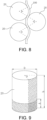
FIG. 9 is a schematic diagram comparing a heat dissipation area of a cylindrical battery of the disclosure and a heat dissipation area of a conventional cylindrical battery. - 10: casing; 20: cylindrical battery;21: terminal; 22: rolling groove; 30: cold plate; 40: thermally conductive structural glue; 50: busbar; 60: fixing bracket; 61: buckle; 62: through hole; 70: mica sheet; 80: tray.
- The implementation of the disclosure is illustrated below by specific embodiments. A person having ordinary skill in the art can easily understand other advantages and effects of the disclosure from the content disclosed in this specification. The disclosure can also be implemented or applied through other different specific implementation ways. The details in this specification can also be modified or changed based on different viewpoints and applications without departing from the spirit of the disclosure. Note that the following embodiments and the features in the embodiments may be combined with each other in the case of no conflict.
- It should be noted that the drawings provided in the following embodiments are merely schematically illustrating the basic idea of the disclosure. Therefore, the drawings only show components related to the disclosure rather than drawings which are depicted according to the numbers, shapes, and sizes of the components in actual implementation. In actual implementation, the types, numbers, and proportions of the components can be changed arbitrarily, and the component layout type may also be more complex.
- It should be noted that a
cylindrical battery 20 provided by the disclosure is a winding-cell cylindrical battery including an outer casing and a winding cell received in the outer casing. The winding cell is formed by rolling a positive electrode piece, a negative electrode piece, and a necessary separator. The positive electrode piece and the negative electrode piece are coated with active materials, and the separator is located between the positive electrode piece and the negative electrode piece. Two ends of the winding cell are provided with a positive electrode tab and a negative electrode tab. Generally, the positive electrode tab is electrically connected to a terminal 21, and the negative electrode tab is electrically connected to the outer casing or an explosion-proof valve. The terminal 21 and the explosion-proof valve are located at both ends of the outer casing, and a necessary insulating structure is provided between the terminal 21 and the outer casing. Compared to the conventional battery structures, the winding-cell battery has higher energy density, and therefore, are widely used in power batteries for electric vehicles. - The technical solutions provided by the disclosure will be described in detail in the following paragraphs with reference to specific embodiments.
- With reference to
FIG. 1 to FIG. 5 , an embodiment of the disclosure provides a battery pack including atray 80 and a plurality of battery modules received in thetray 80. A bottom portion of thetray 80 is provided with acold plate 30, and each of the battery modules includes acasing 10 and a plurality ofcylindrical batteries 20. First ends of thecylindrical batteries 20 are provided withterminals 21. Thecylindrical batteries 20 are received in thecasing 10, and each of thecylindrical batteries 20 is configured in a way that heat conduction may generate between the terminal 21 and thecold plate 30. It should be noted that thecylindrical batteries 20 export current from theterminals 21 and generate a large amount of heat. Compared to export of heat from the outer casings of thecylindrical batteries 20, direct export of heat from the terminals is more efficient. Further, the outer casings of thecylindrical batteries 20 are generally steel casings, and theterminals 21 are generally aluminum or copper terminals, so the material of theterminals 21 has better thermal conductivity. Therefore, theterminals 21 of thecylindrical batteries 20 have better thermal conductivity than the outer casings. In the disclosure, the heat conduction between theterminals 21 and thecold plate 30 is used to achieve the heat dissipation of thecylindrical batteries 20, so the heat dissipation efficiency may be effectively improved. Further, it should be understood that arranging thecold plate 30 at the bottom portions of the batteries is a mainstream design in the field of power batteries. In the disclosure, by establishing heat conduction between theterminals 21 and thecold plate 30 on the bottom of thetray 80, the heat dissipation structure of the battery pack may be modified without changing an existing process of thetray 80, so that the design, development, and manufacturing costs of the battery pack are effectively reduced. - It should be understood that this embodiment is intended to protect the heat dissipation structure of a new
cylindrical battery 20. That is, heat is dissipated through the terminal 21, and any solution that can achieve heat conduction between theterminals 21 and thecold plate 30 should fall within the scope of protection of the disclosure. Therefore, the installation position of thecold plate 30 of the disclosure is not unique. For instance, in some other embodiments, thecold plate 30 may also be a part of each of the battery modules, for example, thecold plate 30 may be used as the bottom plate of each of the battery modules. - With reference to
FIG. 2, FIG. 3 , andFIG. 4 , in a specific embodiment, the first ends of thecylindrical batteries 20 face downward. Abusbar 50 is provided between the first end of each of thecylindrical batteries 20 and thecold plate 30, and thecylindrical batteries 20 are connected in parallel or in series through thebusbars 50. It should be understood that thecylindrical batteries 20 in this embodiment form heat conduction with thecold plate 30 through theterminals 21 and thebusbars 50, and the heat dissipation efficiency of theterminals 21 and thebusbars 50 is better than the heat dissipation efficiency of the outer casings of thecylindrical batteries 20. - With reference to
FIG. 3 , in a further embodiment, slits are provided between side walls of thecylindrical batteries 20. In order to further improve the heat dissipation efficiency between theterminals 21 and thecold plate 30, and heat dissipation efficiency between thebusbars 50 and thecold plate 30, a thermal conductive medium may also be filled between the first ends of thecylindrical batteries 20 and thecold plate 30. For instance, thermally conductivestructural glue 40 is filled between the first ends of thecylindrical batteries 20 and thecold plate 30. The thermally conductive structural glue is in a fluid state during the pouring process and can be completely cured after pouring. Therefore, in this embodiment, the thermally conductive structural glue not only serves as a thermally conductive medium for heat dissipation, but is also a part of the structural component of the battery pack and can effectively fix the batteries. In a specific embodiment, the thermally conductive structural glue may be, for example, a mixture of a resin matrix such as epoxy resin or polyurethane and a thermally conductive filler such as aluminum nitride or silicon nitride. Further, for example, a space between the first ends of thecylindrical batteries 20 and thecold plate 30 and part of a region on a side surface of each of thecylindrical batteries 20 close to the first end may be filled with the thermally conductivestructural glue 40, so the thermal conductivity efficiency is further improved. In this way, the heat dissipation efficiency of thecylindrical batteries 20 may be ensured, a glue filling process may be simplified, the glue filling efficiency is improved, and the overall structural strength of the battery modules and battery pack may also be improved. In this embodiment, thebusbars 50 are wrapped in the thermally conductivestructural glue 40. It should be understood that in some embodiments, the thermally conductivestructural glue 40 may, for example, fill the entire region in a height direction of thecylindrical batteries 20. - With reference to
FIG. 3 andFIG. 4 , in a specific embodiment, a minimum gap among gaps between the side surfaces of thecylindrical batteries 20 is 1 mm to 10 mm, for example, it may be 3 mm, 5 mm or 8 mm. This gap size may not only ensure that the thermally conductivestructural glue 40 has good fluidity to be able to fully fill these gaps, but also prevent the energy density of the battery pack from being affected by an excessive gap. - In a specific embodiment, in the disclosure, a glue filling height ratio on the side surface of each of the
cylindrical batteries 20 is limited, so that the heat dissipation efficiency of thecylindrical batteries 20 is ensured, the glue filling process is simplified to the greatest extent, and the glue filling efficiency is improved. - With reference to
FIG. 8 , in a conventional cylindrical battery heat dissipation solution, a wrapping angle α of aserpentine tube 100 on each of thecylindrical batteries 20 is generally about 60°, then a heat exchange area S1 between each of thecylindrical batteries 20 and theserpentine tube 100 is:
- With reference to
FIG. 9 , herein, D is a diameter of thecylindrical battery 20, and h is a total height of thecylindrical battery 20. - But in this embodiment, a heat dissipation area S of the
cylindrical battery 20 is an end surface area of thecylindrical battery 20 plus an area of a glue filling region on the side surface of thecylindrical battery 20, that is:
- With reference to
FIG. 9 , herein, A is a height of the glue filling region on the side surface of thecylindrical battery 20. - To achieve the same heat exchange area as the conventional heat dissipation solution in this embodiment, we only need to make S=S1, that is:


- It can be seen from the above calculation that to make the heat exchange area of this embodiment larger than the heat dissipation area of the conventional solution, the following condition is only required to be met:

- The common specifications of the
cylindrical batteries 20 and the side glue filling height ratio calculated according to the above method are as shown in the following table:D h A/h 46 80 0.022917 46 90 0.045614 46 120 0.070833 18 65 0.097436 21 70 0.091667 - It can be seen from the above data that in this embodiment, a smaller glue filling height can obtain a larger heat exchange area than the conventional heat dissipation solution, so that the glue filling process is greatly simplified, and the battery production costs are saved.
- In a further embodiment, the height A of the region filled with the thermally conductive structural glue on the side surface of each of the cylindrical batteries and the total height h of the cylindrical battery satisfies:

- It should be understood that the high consistency of glue filling is not easy to control. If the glue filling height is too close to a top surface of each of the batteries, the glue may easily overflow, causing the explosion-proof valve to be contaminated and thermal safety to be affected. In this embodiment, the glue filling height is limited to less than 95% of the battery height, so that the above problems are effectively prevented from occurring.
- With reference to
FIG. 2, FIG. 3 , andFIG. 5 , in a further embodiment, a fixingbracket 60 is disposed at second ends of thecylindrical batteries 20. The fixingbracket 60 is provided with a plurality of throughholes 62 arranged in an array. The second ends of thecylindrical batteries 20 are relatively and fixedly installed on the fixingbracket 60. For instance, the second ends of thecylindrical batteries 20 extend into the throughholes 62 and are fixed, or are fixed to a lower surface of the fixingbracket 60 by gluing. It should be understood that when the side surfaces of thecylindrical batteries 20 are partially filled with glue, the second ends of thecylindrical batteries 20 are in a suspended state. Therefore, in the disclosure, the fixingbracket 60 is provided at the second ends of thecylindrical batteries 20. The fixingbracket 60 may keep the second ends of thecylindrical batteries 20 relatively fixed, so that the stability of the cylindrical batteries is improved, and the overall structural strength of the battery pack is improved. - With reference to
FIG. 5 , in a preferred embodiment, an edge of the through hole is provided with abuckle 61, and thebuckle 61 is engaged with a rolling groove on the side wall of thecylindrical battery 20. It should be understood that the outer casing of thecylindrical battery 20 is generally slightly longer than an inner winding cell. Therefore, in order to prevent the winding cell from generating axial displacement in the outer casing, a ring of rollinggroove 22 is generally arranged on the side wall of the outer casing close to the second end, and an inner end of the rollinggroove 22 is in contact with an end surface edge of the winding cell to limit a position of the winding cell. In this embodiment, the rollinggroove 22 is used to limit a position of the fixingbracket 60, and thebuckle 61 is engaged with the rollinggroove 22 to keep the fixingbracket 60 and each of thecylindrical batteries 20 relatively fixed, so that the fixingbracket 60 is prevented from slipping along an axis of thecylindrical battery 20. - With reference to
FIG. 2 , in a further embodiment, the second ends of thecylindrical batteries 20 are covered with amica sheet 70 from above. It should be understood that themica sheet 70 has good fire-retardant properties. When thermal runaway occurs in onecylindrical battery 20, for example, one single battery fails or multiple batteries fail, the explosion-proof valve provided at the second end of thiscylindrical battery 20 opens and breaks through a portion of the mica sheet corresponding to thiscylindrical battery 20. However, the mica above other non-failedcylindrical batteries 20 is not destroyed, so the high-temperature substances emitted by the failedcylindrical battery 20 may not fall to the second ends of the normalcylindrical batteries 20, thereby avoiding a chain reaction of thermal runaway. The safety of the battery pack is thereby improved. In a specific embodiment, in order to make it easier for high-temperature substances to break through themica sheet 70, for example, a weak portion may be provided in a region on themica sheet 70 corresponding to each of the explosion-proof valves. - It should be understood that, inspired by the above embodiments, other simple modifications based on the above embodiments should also fall within the protection scope of the disclosure. For example, in an alternative embodiment, the battery modules may be eliminated and the
cylindrical batteries 20 are directly installed upside down in thetray 80. Theterminals 21 of thecylindrical batteries 20 may also realize heat conduction with thecold plate 30 at the bottom portion of thetray 80, which is in line with the design concept of the disclosure, and the technical effects of the disclosure are achieved. - With reference to
FIG. 6 andFIG. 7 , this embodiment is a possible modification based on Embodiment 1, and the only difference between this embodiment and Embodiment 1 is: theterminals 21 of thecylindrical batteries 20 in this embodiment face upward. Correspondingly, thebusbars 50 and thecold plate 30 in this embodiment are located at upper ends of thecylindrical batteries 20. Similarly, thecold plate 30 in this embodiment may be an upper cover of the battery pack or an upper cover of the battery modules. It should be understood that in this embodiment, the battery modules may also be eliminated, and thecylindrical batteries 20 may be directly installed in thetray 80. In this embodiment, local glue filling may also be used to fill the thermally conductivestructural glue 40 between theterminals 21 and thecold plate 30 of thecylindrical batteries 20 and in part of the region of the side wall of each of thecylindrical batteries 20 close to the first end. - In view of the foregoing, in the disclosure, the heat conduction between the
terminals 21 and thecold plate 30 is used to achieve the heat dissipation of thecylindrical batteries 20, so the heat dissipation efficiency is effectively improved. In the disclosure, by establishing heat conduction between theterminals 21 and thecold plate 30 on the bottom of thetray 80, the heat dissipation structure of the battery pack may be modified without changing the existing process of thetray 80, so that the design, development, and manufacturing costs of the battery pack are effectively reduced. The space between the first ends of thecylindrical batteries 20 and thecold plate 30 and part of a region on the side surface of each of thecylindrical batteries 20 close to the first end are filled with the thermally conductivestructural glue 40. In this way, the heat dissipation efficiency of thecylindrical batteries 20 is ensured, the glue filling process is simplified, and the glue filling efficiency is improved. In the disclosure, the fixingbracket 60 is provided at the second ends of thecylindrical batteries 20. The fixingbracket 60 keeps the second ends of thecylindrical batteries 20 relatively fixed, so that the stability of the cylindrical batteries is improved, and the overall structural strength of the battery pack is improved. In the disclosure, the rollinggroove 22 is used to limit the position of the fixingbracket 60, and thebuckle 61 is engaged with the rollinggroove 22 to keep the fixingbracket 60 and each of thecylindrical batteries 20 relatively fixed, so that the fixingbracket 60 is prevented from slipping along the axis of thecylindrical battery 20.
Claims (13)
- A battery module, comprising:a casing (10); anda plurality of cylindrical batteries (20) received in the casing (10), wherein first ends of the cylindrical batteries (20) are provided with terminals (21), and the first ends of the cylindrical batteries (20) facing an inner wall of the casing (10),a space between the first ends of the cylindrical batteries (20) and the inner wall of the casing (10) and part of a region on a side surface of each of the cylindrical batteries (20) close to the first end being filled with thermally conductive structural glue (40).
- The battery module according to claim 1, wherein gaps are provided between the side surfaces of the cylindrical batteries (20).
- The battery module according to claim 1 or 2, wherein a minimum gap among the gaps between the side surfaces of the cylindrical batteries (20) is 1 mm to 10 mm.
- The battery module according to any one of claims 1 to 3, wherein a height of the region filled with the thermally conductive structural glue (40) on the side surface of each of the cylindrical batteries (20) is A, and a total height of the cylindrical battery (20) is h, then

- The battery module according to any one of claims 1 to 4, wherein the height A of the region filled with the thermally conductive structural glue (40) on the side surface of each of the cylindrical batteries (20) and the total height h of the cylindrical battery (20) satisfies:

- The battery module according to any one of claims 1 to 5, wherein a busbar (50) is provided between the first end of each of the cylindrical batteries (20) and the casing (10), and the busbar (50) is wrapped in the thermally conductive structural glue (40).
- The battery module according to any one of claims 1 to 6, wherein the first ends of the cylindrical batteries (20) face a bottom plate or a top plate of the casing (10).
- The battery module according to any one of claims 1 to 7, further comprising a fixing bracket (60) disposed at second ends of the cylindrical batteries (20), wherein the second end of each of the cylindrical batteries (20) comprises an explosion-proof valve, and the fixing bracket (60) is provided with a plurality of through holes (62) arranged in an array opposite to the cylindrical batteries (20).
- The battery module according to any one of claims 1 to 8, wherein the explosion-proof valves are covered with a mica sheet (70) from above.
- The battery module according to any one of claims 1 to 9, wherein a weak portion is provided in a region of the mica sheet (70) corresponding to each of the explosion-proof valves.
- The battery module according to any one of claims 1 to 10, wherein an edge of each of the through holes (62) is provided with a buckle (61), and the buckle (61) is engaged with a rolling groove (22) on a side wall of each of the cylindrical batteries (20).
- A battery pack, comprising:the battery module according to any one of claims 1 to 11; anda tray (80) provided with a cold plate (30),wherein the battery module is received in the tray (80) and is configured in a way that the first ends of the cylindrical batteries (20) face the cold plate (30).
- A battery pack, comprising:a tray (80) provided with a cold plate (30); anda plurality of cylindrical batteries (20), wherein first ends of the cylindrical batteries (20) are provided with terminals (21), the cylindrical batteries (20) are received in the tray (80), and the first ends of the cylindrical batteries (20) face the cold plate (30),a space between the first ends of the cylindrical batteries (20) and the cold plate (30) and part of a region on a side surface of each of the cylindrical batteries (20) close to the first end are filled with thermally conductive structural glue (40).
Applications Claiming Priority (1)
| Application Number | Priority Date | Filing Date | Title |
|---|---|---|---|
| CN202321086429.8U CN220065796U (en) | 2023-05-08 | 2023-05-08 | Battery module and battery pack |
Publications (2)
| Publication Number | Publication Date |
|---|---|
| EP4462551A2 true EP4462551A2 (en) | 2024-11-13 |
| EP4462551A3 EP4462551A3 (en) | 2025-02-19 |
Family
ID=88749755
Family Applications (1)
| Application Number | Title | Priority Date | Filing Date |
|---|---|---|---|
| EP23218037.2A Pending EP4462551A3 (en) | 2023-05-08 | 2023-12-19 | Battery module and battery pack |
Country Status (4)
| Country | Link |
|---|---|
| US (1) | US20240380020A1 (en) |
| EP (1) | EP4462551A3 (en) |
| JP (1) | JP7650342B2 (en) |
| CN (1) | CN220065796U (en) |
Families Citing this family (3)
| Publication number | Priority date | Publication date | Assignee | Title |
|---|---|---|---|---|
| US12555840B2 (en) * | 2024-06-20 | 2026-02-17 | Estes Energy Solutions, Inc. | Thermo-structural battery packs and systems |
| EP4679594A1 (en) * | 2024-07-11 | 2026-01-14 | Eve Energy Co., Ltd. | Battery pack and electric apparatus |
| CN119601877A (en) * | 2024-12-30 | 2025-03-11 | 惠州亿纬锂能股份有限公司 | Battery pack and battery pack production method |
Family Cites Families (14)
| Publication number | Priority date | Publication date | Assignee | Title |
|---|---|---|---|---|
| JP2003115289A (en) | 2001-10-03 | 2003-04-18 | Japan Storage Battery Co Ltd | Battery pack of cylindrical battery |
| JP3782393B2 (en) | 2001-12-28 | 2006-06-07 | 株式会社東芝 | Battery pack and rechargeable vacuum cleaner |
| KR102292216B1 (en) | 2017-02-20 | 2021-08-24 | 테슬라, 인크. | Energy storage pack |
| KR102204303B1 (en) | 2017-10-27 | 2021-01-15 | 주식회사 엘지화학 | Battery module having fixing structure intergrated with cooling material for battery cells and Battery pack including the same |
| EP3503244A1 (en) * | 2017-12-19 | 2019-06-26 | Hilti Aktiengesellschaft | Battery pack for a hand tool |
| DE102018202114A1 (en) | 2018-02-12 | 2019-08-14 | Airbus Defence and Space GmbH | Battery assembly for the structural integration of batteries in a vehicle |
| EP4024421A4 (en) | 2019-08-30 | 2022-12-07 | Panasonic Intellectual Property Management Co., Ltd. | ELECTRICITY STORAGE MODULE |
| KR102873691B1 (en) | 2020-01-22 | 2025-10-17 | 주식회사 엘지에너지솔루션 | Battery module |
| KR102729323B1 (en) | 2020-06-05 | 2024-11-11 | 삼성에스디아이 주식회사 | Rechargeable battery pack |
| KR102864926B1 (en) | 2020-08-21 | 2025-09-26 | 주식회사 엘지에너지솔루션 | Battery Module With Improved Cooling Performance and Method of Manufacturing the Same |
| JP7536897B2 (en) | 2021-01-11 | 2024-08-20 | エルジー エナジー ソリューション リミテッド | Battery pack and automobile including same |
| JP7627289B2 (en) * | 2021-01-11 | 2025-02-05 | エルジー エナジー ソリューション リミテッド | Battery pack and automobile including same |
| KR102875709B1 (en) | 2021-02-22 | 2025-10-23 | 주식회사 엘지에너지솔루션 | Battery pack and vehicle comprising the battery pack |
| CN113937404B (en) | 2021-09-30 | 2023-07-14 | 蜂巢能源科技有限公司 | Cylindrical battery module |
-
2023
- 2023-05-08 CN CN202321086429.8U patent/CN220065796U/en active Active
- 2023-12-07 US US18/533,096 patent/US20240380020A1/en active Pending
- 2023-12-11 JP JP2023208437A patent/JP7650342B2/en active Active
- 2023-12-19 EP EP23218037.2A patent/EP4462551A3/en active Pending
Also Published As
| Publication number | Publication date |
|---|---|
| EP4462551A3 (en) | 2025-02-19 |
| JP2024161880A (en) | 2024-11-20 |
| CN220065796U (en) | 2023-11-21 |
| JP7650342B2 (en) | 2025-03-24 |
| US20240380020A1 (en) | 2024-11-14 |
Similar Documents
| Publication | Publication Date | Title |
|---|---|---|
| US20240380020A1 (en) | Battery module and battery pack | |
| EP3706189B1 (en) | Battery module and battery pack | |
| US8920955B1 (en) | Battery module with high thermal conductivity and assembling method thereof | |
| KR102210218B1 (en) | Battery system, base plate for a battery system and electric vehicle | |
| CN103390762B (en) | The high heat conduction battery modules of the most battery of tool and assemble method thereof | |
| US20250112326A1 (en) | Battery pack | |
| CN210926233U (en) | Battery module and battery pack | |
| CN217788692U (en) | Battery pack | |
| CN209592168U (en) | Battery module, battery system and electric vehicle with the battery module | |
| CN220420672U (en) | Battery pack and vehicle with same | |
| CN219163629U (en) | Battery pack and power device | |
| CN218586230U (en) | Battery module, battery package and consumer | |
| CN115411421A (en) | Battery module, battery package and consumer | |
| CN217062327U (en) | Battery pack | |
| CN219350594U (en) | Battery cell structure and battery | |
| CN119786852A (en) | Battery pack, method for manufacturing battery pack, and electrical equipment | |
| CN115579586B (en) | Battery packs and electrical equipment | |
| CN209526135U (en) | Battery module, battery component, battery modules, battery system and electric vehicle | |
| CN220544113U (en) | Battery pack structure and battery | |
| CN223898359U (en) | Battery pack and electricity utilization device | |
| US20250239689A1 (en) | Liquid-cooled battery pack | |
| CN217848242U (en) | Full-lug battery pack assembly, battery module and battery pack | |
| CN224191148U (en) | Battery modules and electrical devices | |
| CN218351595U (en) | Power battery | |
| CN221102308U (en) | Soft packet of electric core module |
Legal Events
| Date | Code | Title | Description |
|---|---|---|---|
| PUAI | Public reference made under article 153(3) epc to a published international application that has entered the european phase |
Free format text: ORIGINAL CODE: 0009012 |
|
| STAA | Information on the status of an ep patent application or granted ep patent |
Free format text: STATUS: REQUEST FOR EXAMINATION WAS MADE |
|
| 17P | Request for examination filed |
Effective date: 20231219 |
|
| AK | Designated contracting states |
Kind code of ref document: A2 Designated state(s): AL AT BE BG CH CY CZ DE DK EE ES FI FR GB GR HR HU IE IS IT LI LT LU LV MC ME MK MT NL NO PL PT RO RS SE SI SK SM TR |
|
| PUAL | Search report despatched |
Free format text: ORIGINAL CODE: 0009013 |
|
| AK | Designated contracting states |
Kind code of ref document: A3 Designated state(s): AL AT BE BG CH CY CZ DE DK EE ES FI FR GB GR HR HU IE IS IT LI LT LU LV MC ME MK MT NL NO PL PT RO RS SE SI SK SM TR |
|
| RIC1 | Information provided on ipc code assigned before grant |
Ipc: H01M 50/213 20210101ALI20250115BHEP Ipc: H01M 10/6554 20140101ALI20250115BHEP Ipc: H01M 10/653 20140101ALI20250115BHEP Ipc: H01M 10/643 20140101ALI20250115BHEP Ipc: H01M 10/613 20140101AFI20250115BHEP |
|
| STAA | Information on the status of an ep patent application or granted ep patent |
Free format text: STATUS: EXAMINATION IS IN PROGRESS |
|
| 17Q | First examination report despatched |
Effective date: 20251120 |