EP4462549A1 - Battery safety evaluation device - Google Patents
Battery safety evaluation device Download PDFInfo
- Publication number
- EP4462549A1 EP4462549A1 EP23888960.4A EP23888960A EP4462549A1 EP 4462549 A1 EP4462549 A1 EP 4462549A1 EP 23888960 A EP23888960 A EP 23888960A EP 4462549 A1 EP4462549 A1 EP 4462549A1
- Authority
- EP
- European Patent Office
- Prior art keywords
- battery
- temperature sensor
- virtual line
- mounting plate
- safety evaluation
- Prior art date
- Legal status (The legal status is an assumption and is not a legal conclusion. Google has not performed a legal analysis and makes no representation as to the accuracy of the status listed.)
- Pending
Links
Images

Classifications
-
- H—ELECTRICITY
- H01—ELECTRIC ELEMENTS
- H01M—PROCESSES OR MEANS, e.g. BATTERIES, FOR THE DIRECT CONVERSION OF CHEMICAL ENERGY INTO ELECTRICAL ENERGY
- H01M10/00—Secondary cells; Manufacture thereof
- H01M10/42—Methods or arrangements for servicing or maintenance of secondary cells or secondary half-cells
-
- H—ELECTRICITY
- H01—ELECTRIC ELEMENTS
- H01M—PROCESSES OR MEANS, e.g. BATTERIES, FOR THE DIRECT CONVERSION OF CHEMICAL ENERGY INTO ELECTRICAL ENERGY
- H01M10/00—Secondary cells; Manufacture thereof
- H01M10/42—Methods or arrangements for servicing or maintenance of secondary cells or secondary half-cells
- H01M10/4285—Testing apparatus
-
- G—PHYSICS
- G01—MEASURING; TESTING
- G01K—MEASURING TEMPERATURE; MEASURING QUANTITY OF HEAT; THERMALLY-SENSITIVE ELEMENTS NOT OTHERWISE PROVIDED FOR
- G01K1/00—Details of thermometers not specially adapted for particular types of thermometer
- G01K1/02—Means for indicating or recording specially adapted for thermometers
- G01K1/026—Means for indicating or recording specially adapted for thermometers arrangements for monitoring a plurality of temperatures, e.g. by multiplexing
-
- G—PHYSICS
- G01—MEASURING; TESTING
- G01K—MEASURING TEMPERATURE; MEASURING QUANTITY OF HEAT; THERMALLY-SENSITIVE ELEMENTS NOT OTHERWISE PROVIDED FOR
- G01K1/00—Details of thermometers not specially adapted for particular types of thermometer
- G01K1/14—Supports; Fastening devices; Arrangements for mounting thermometers in particular locations
-
- G—PHYSICS
- G01—MEASURING; TESTING
- G01K—MEASURING TEMPERATURE; MEASURING QUANTITY OF HEAT; THERMALLY-SENSITIVE ELEMENTS NOT OTHERWISE PROVIDED FOR
- G01K13/00—Thermometers specially adapted for specific purposes
-
- G—PHYSICS
- G01—MEASURING; TESTING
- G01K—MEASURING TEMPERATURE; MEASURING QUANTITY OF HEAT; THERMALLY-SENSITIVE ELEMENTS NOT OTHERWISE PROVIDED FOR
- G01K7/00—Measuring temperature based on the use of electric or magnetic elements directly sensitive to heat ; Power supply therefor, e.g. using thermoelectric elements
- G01K7/02—Measuring temperature based on the use of electric or magnetic elements directly sensitive to heat ; Power supply therefor, e.g. using thermoelectric elements using thermoelectric elements, e.g. thermocouples
-
- G—PHYSICS
- G01—MEASURING; TESTING
- G01N—INVESTIGATING OR ANALYSING MATERIALS BY DETERMINING THEIR CHEMICAL OR PHYSICAL PROPERTIES
- G01N25/00—Investigating or analyzing materials by the use of thermal means
- G01N25/72—Investigating presence of flaws
-
- H—ELECTRICITY
- H01—ELECTRIC ELEMENTS
- H01M—PROCESSES OR MEANS, e.g. BATTERIES, FOR THE DIRECT CONVERSION OF CHEMICAL ENERGY INTO ELECTRICAL ENERGY
- H01M10/00—Secondary cells; Manufacture thereof
- H01M10/42—Methods or arrangements for servicing or maintenance of secondary cells or secondary half-cells
- H01M10/48—Accumulators combined with arrangements for measuring, testing or indicating the condition of cells, e.g. the level or density of the electrolyte
-
- H—ELECTRICITY
- H01—ELECTRIC ELEMENTS
- H01M—PROCESSES OR MEANS, e.g. BATTERIES, FOR THE DIRECT CONVERSION OF CHEMICAL ENERGY INTO ELECTRICAL ENERGY
- H01M10/00—Secondary cells; Manufacture thereof
- H01M10/42—Methods or arrangements for servicing or maintenance of secondary cells or secondary half-cells
- H01M10/48—Accumulators combined with arrangements for measuring, testing or indicating the condition of cells, e.g. the level or density of the electrolyte
- H01M10/486—Accumulators combined with arrangements for measuring, testing or indicating the condition of cells, e.g. the level or density of the electrolyte for measuring temperature
-
- Y—GENERAL TAGGING OF NEW TECHNOLOGICAL DEVELOPMENTS; GENERAL TAGGING OF CROSS-SECTIONAL TECHNOLOGIES SPANNING OVER SEVERAL SECTIONS OF THE IPC; TECHNICAL SUBJECTS COVERED BY FORMER USPC CROSS-REFERENCE ART COLLECTIONS [XRACs] AND DIGESTS
- Y02—TECHNOLOGIES OR APPLICATIONS FOR MITIGATION OR ADAPTATION AGAINST CLIMATE CHANGE
- Y02E—REDUCTION OF GREENHOUSE GAS [GHG] EMISSIONS, RELATED TO ENERGY GENERATION, TRANSMISSION OR DISTRIBUTION
- Y02E60/00—Enabling technologies; Technologies with a potential or indirect contribution to GHG emissions mitigation
- Y02E60/10—Energy storage using batteries
Definitions
- the present disclosure relates to a battery safety evaluation apparatus, and to a battery safety evaluation apparatus capable of quantitatively analyzing location and temperature of gas and flame emitted from a battery over time.
- a sealed chamber is used to ensure the safety of researchers during battery experiments that have the risk of ignition and explosion, as well as to collect and analyze gases generated from the battery.
- the composition and amount of gas generated from the battery vary in real time depending on the kinetic characteristics (SOC, battery temperature, evaluation atmospheric environmental conditions, etc.).
- the physical properties of the gas such as temperature and density, also change.
- Identifying the location and temperature distribution of gas and flame emitted outside the battery when excessive gas is generated inside the battery or when the battery ignites is very important in designing the battery itself and a device containing the battery.
- thermo imaging camera was used to measure the temperature distribution of the gas and flame generated and emitted from a battery.
- the thermal imaging camera When installing a thermal imaging camera inside a chamber for battery analysis, the thermal imaging camera may be damaged by harsh conditions within the chamber, and it was difficult to operate a cooling device for the thermal imaging camera inside the chamber.
- a window made of a material capable of transmitting infrared rays is required by the chamber, and chambers designed in consideration of explosion-proof, and the like, have limitations in the size of the window, so there was also a limit to the scale of measurement.
- the present disclosure relates to a battery safety evaluation apparatus, and is to provide a battery safety evaluation apparatus capable of quantitatively analyzing location and temperature of gas and flame emitted from a battery over time.
- a battery safety evaluation apparatus of the present disclosure may include:
- a battery safety evaluation apparatus of the present disclosure may be capable of effectively analyzing real-time temperature distribution due to gas and flame emitted from a battery located inside a chamber.
- a battery safety evaluation apparatus of the present disclosure may be capable of quantifying location and temperature of the gas and flame emitted from the inside of the battery to the outside over time.
- a battery safety evaluation apparatus of the present disclosure may maximize the reproducibility of analysis by minimizing parts consumed for repeated measurements.
- a battery safety evaluation apparatus of the present disclosure may include:
- the mounting plate of the battery safety evaluation apparatus of the present disclosure may be plate shaped, has a width in a first direction, and extends in a second direction, wherein the second direction is perpendicular to the first direction and the first direction and the second direction are perpendicular to the vertical direction.
- At least one of the plurality of temperature sensor units may be arranged on a first virtual line extending in the second direction; and at least one of the plurality of temperature sensor units may be arranged on a second virtual line extending in the second direction, wherein the battery is between the first virtual line and the second virtual line.
- a temperature sensor of the plurality of temperature sensor units may be located at an intersection of the first virtual line and a third virtual line extending in the first direction; a temperature sensor of the plurality of temperature sensor units may be located at an intersection of the second virtual line and the third virtual line; a temperature sensor of the plurality of temperature sensor units may be located at an intersection of the first virtual line and a fourth virtual line extending in the first direction; and a temperature sensor of the plurality of temperature sensor units may be located at an intersection of the second virtual line and the fourth virtual line, wherein the battery is between the third virtual line and the fourth virtual line.
- a temperature sensor of the plurality of temperature sensor units may be located at an intersection of the first virtual line and a fifth virtual line extending in the first direction; and a temperature sensor of the plurality of temperature sensor units may be located at an intersection of the second virtual line and the fifth virtual line, and the fifth virtual line is between one end of the battery and the other end of the battery.
- the temperature sensor unit may be a rod shaped and extends in the vertical direction.
- the temperature sensor unit may include a first measurement point and a second measurement point, wherein the first measurement point may be above the mounting plate, and the second measurement point may be below the mounting plate.
- the temperature sensor unit may further include a third measurement point located between the first measurement point and the second measurement point, and the third measurement point may be above the mounting plate.
- the chamber unit may include a body unit in which one end in the second direction is opened to form an opening and the battery accommodation space is formed inside, and a door unit coupled to the body unit and configured to cover the opening, wherein one end of the mounting plate in the second direction may be coupled to a surface of the door unit facing the opening, and the other end of the mounting plate in the second direction may be in the battery accommodation space.
- an upper end of a temperature sensor unit of the plurality of temperature sensor units may be fixed to a ceiling surface of the chamber unit, and a spacing between the first virtual line and the second virtual line may be longer than a length of the mounting plate in the first direction.
- a temperature sensor unit of the plurality of temperature sensor units may be fixed to the mounting plate in a state of penetrating the mounting plate, and a spacing between the first virtual line and the second virtual line may be shorter than a length of the mounting plate in the first direction and longer than a length of the battery in the first direction.
- the door unit may include a feed-through for connecting the plurality of temperature sensor units to the temperature analysis unit by wire.
- the battery safety evaluation apparatus of the present disclosure may further include a lower jig with a bottom surface fixed on the upper surface of the mounting plate; a first insulating layer between the battery and the lower jig; an upper jig for pressurizing the upper surface of the battery; a second insulating layer between the upper jig and the upper surface of the battery; a bottom surface temperature measurement sensor between the first insulating layer and the battery; and an upper surface temperature measurement sensor between the second insulating layer and the battery.
- the battery safety evaluation apparatus of the present disclosure may further include a first fixing means for fixing the upper jig to the lower jig; and a second fixing means for fixing the lower jig to the mounting plate.
- an orientation or positional relationship indicated by the terms such as “center”, “upper”, “lower”, “left”, “right”, “vertical”, “horizontal”, “inner side”, “outer side”, “one side”, and “other side” is based on an orientation or positional relationship shown in a drawing or an orientation or positional relationship that is placed when using the product of the present disclosure on a daily basis, and is merely for explanation and brief description of the present disclosure, and it does not suggest or imply that the displayed device or element must necessarily be configured or operated in a specified orientation and should not be construed as limiting the present disclosure.
- FIG. 1 is a cross-sectional view illustrating a battery safety evaluation apparatus of the present disclosure.
- FIG. 2 is a plan view illustrating a positional relationship between a temperature sensor unit 100 and a battery 11.
- FIG. 3 is a cross-sectional view illustrating a chamber unit 300.
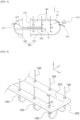
- FIG. 4 is a perspective view illustrating an embodiment in which the temperature sensor unit 100 is coupled to a mounting plate 200.
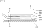
- FIG. 5 is a perspective view illustrating an embodiment in which the battery 11 is fixed to the mounting plate 200.
- the y-axis direction may be a first direction
- the x-axis direction may be a second direction
- the z-axis direction may be a vertical direction.
- the vertical direction which is the z-axis direction, may be the direction of gravity.
- gravity may act to bring a bottom surface of the battery 11 into close contact with an upper surface of the mounting plate 300.
- a battery safety evaluation apparatus of the present disclosure may include:
- the battery safety evaluation apparatus of the present disclosure may dispose the plurality of temperature sensor units 100 around the battery 11 within the sealed chamber unit 300, collect temperature measurement values at a predetermined time period from the plurality of temperature sensor units 100 disposed, and calculate thermal mapping data as time series data indicating situations in which the battery 11 is damaged in situations such as explosion or leakage of the battery 11.
- the temperature analysis unit 400 may receive the temperature measurement values output from the temperature sensor units 100.
- the temperature analysis unit 400 may store position information and identification codes for each of the plurality of temperature sensor units 100.
- the temperature measurement value received from the plurality of temperature sensor units 100 may be stored by matching the identification code corresponding to each of the plurality of temperature sensor units 100.
- the temperature analysis unit 400 may receive temperature measurement values from the temperature sensor units 100 at a predetermined time period and calculate temperature analysis data as time series data.
- the temperature analysis unit 400 may be a computing device.
- the temperature analysis unit 400 may be connected to a display device and may output temperature analysis data to the display device.
- the temperature analysis unit 400 may be located outside the chamber unit 300, and a feed-through 321 may be provided on a wall of the chamber unit 300 for electrical connection with the temperature sensor unit 100, a charge/discharge cable 410, a heater inside the chamber unit 300, or the like.
- the temperature analysis unit 400 may forcibly impose conditions such as explosion or damage on the battery 11 by controlling a charge/discharge module, a heater, or the like.
- the mounting plate 200 may be provided in a plate shape having a constant width in a first direction perpendicular to a vertical direction and extending in a second direction perpendicular to the vertical direction and the first direction.
- the battery 11 may be mounted on the upper surface of the mounting plate 200.
- the battery 11 may be fixed by directly contacting the mounting plate 200, or may be fixed to the mounting plate 200 through an upper jig 220 and a lower jig 210, which will be described later.
- the battery 11 to be analyzed may be, for example, a pouch-type battery 11. Specifically, it may be the battery 11 including flat shape electrodes (anode, cathode) perpendicular to the vertical direction. More specifically, the electrode may be provided in a rectangular shape with a side length in the second direction longer than that in the first direction.
- first virtual line I1 and a second virtual line l2 when a pair of virtual straight lines extending in the second direction with the battery 11 in between are referred to as a first virtual line I1 and a second virtual line l2, at least one of the plurality of temperature sensor units 100 may be arranged on each of the first virtual line 11 and the second virtual line l2.
- 2 to 10 temperature sensor units 100 On each of the first virtual line 11 and the second virtual line l2, 2 to 10 temperature sensor units 100 may be arranged.
- 3 or 7 temperature sensor units 100 may be arranged on each of the first virtual line 11 and the second virtual line l2 of the temperature sensor unit 100.
- the number of temperature sensor units 100 arranged on each of the first virtual line 11 and the second virtual line l2 may be determined by considering conditions such as the standard, material, and structure of the battery 11, or insulation and explosion-proof of the structure to which the battery 11 is applied and installed.
- a spacing between the first virtual line 11 and the second virtual line l2 may be 110% to 150% of a length of the battery 11 in the first direction.
- the interval between the first virtual line 11 and the second virtual line l2 may be 240 mm to 360 mm.
- the interval between the first virtual line 11 and the second virtual line l2 may be about 300 mm.
- the battery safety evaluation method of the present disclosure may be to determine the temperature around the battery 11 in real time and analyze thermal behavior in a situation where the battery 11 explodes or ignites.
- the chamber unit 300 may be formed to have an explosion-proof structure that may withstand high pressure, high heat, explosion, and the like, during analysis.
- the chamber unit 300 may be provided in a cylindrical shape extending in the second direction for the explosion-proof structure.
- the volume of the battery accommodation space 311 of the chamber unit 300 may become excessively large because the temperature sensor unit 100 may also be provided in a rod shape extending in the vertical direction.
- a space in which a battery-generated gas generated inside the battery 11 diffuses becomes larger, which may make it difficult to analyze the battery-generated gas.
- the temperature sensor unit 100 is located too close to the battery 11, when the battery 11 explodes or ignites, the temperature sensor unit 100 may be damaged, or the temperature sensor unit 100 itself may affect the airflow around the battery 11. Accordingly, the interval between the first virtual line 11 and the second virtual line l2 may be 110% to 150% of the length of the battery 11 in the first direction.
- the plurality of temperature sensor units 100 may be disposed at an intersection point P1 of the third virtual line l3 and the first virtual line 11, an intersection point P2 of the third virtual line l3 and the second virtual line l2, an intersection point P3 of the fourth virtual line l4 and the first virtual line 11, and an intersection point P4 of the fourth virtual line l4 and the second virtual line l2.
- a spacing between the third virtual line l3 and the fourth virtual line l4 may be 110% to 150% of a length of the battery 11 in the second direction.
- the interval between the third virtual line l3 and the fourth virtual line l4 may be 1 640 mm to 960 mm.
- the interval between the third virtual line l3 and the fourth virtual line l4 may be l about 800 mm.
- the plurality of temperature sensor units 100 may be further disposed at an intersection point P5 of the fifth virtual line l5 and the first virtual line l1, and an intersection point P6 of the fifth virtual line l5 and the second virtual line l2.
- a sixth virtual line (not shown), which is a straight line extending in the second direction, may be located, and the temperature sensor unit 100 may be located at each of the intersection point between the sixth virtual line and the third virtual line l3, and the intersection point between the sixth virtual line and the fourth virtual line l4.
- a plurality of the fifth virtual lines l5 may be provided.
- one temperature sensor unit 100 may have 3 measurement points, as will be described later. Therefore, in the battery accommodation space 311 of the battery safety evaluation apparatus of the present disclosure, temperature may be measured at 48 points, and the temperature measurement value may be provided as time series data (temperature-time graph) for each of the 48 points.
- the temperature sensor unit 100 may be provided in a rod shape extending in the vertical direction.
- the temperature sensor unit 100 may be a thermocouple (TC) with high heat resistance.
- One temperature sensor unit 100 may include a plurality of temperature measurement points.
- the temperature sensor unit 100 may include a first measurement point (t) and a second measurement point (b), wherein the first measurement point (t) may be located at a higher position than the mounting plate 200, and the second measurement point (b) may be located at a lower position than the mounting plate 200. More specifically, the first measurement point (t) may be located at a higher position than an upper surface of the battery 11, and the second measurement point (b) may be located at a lower position than the bottom surface of the battery 11.
- the temperature sensor unit 100 may further include a third measurement point (m) located between the first measurement point (t) and the second measurement point (b), wherein the third measurement point (m) may be located at a higher position than the mounting plate 200. More specifically, the third measurement point (m) may be formed at a position facing the side surface of the battery 11.
- each of the plurality of temperature sensor units 100 may have three temperature measurement points, and for example, when six temperature sensor units 100 are provided, the temperature analysis unit 400 may output temperature measurement data for a total of 18 points. For example, 18 graphs of temperature over time may be output from the temperature analysis unit 400.
- the chamber unit 300 may include a body unit 310 in which one end in the second direction is opened to form an opening 312 and the battery accommodation space 311 is formed inside, and a door unit 320 coupled to the body unit 310 and configured to cover the opening 312, wherein one end of the mounting plate 200 in the second direction may be coupled to a surface of the door unit 320 facing the opening 312, and the other end of the mounting plate 200 in the second direction may be inserted into the battery accommodation space 311 through the opening 312.
- the door unit 320 may be coupled to or separated from the body unit 310 while sliding in the second direction and moving linearly.
- the mounting plate 200 may move together with the door unit 320 and be inserted into the battery accommodation space 311 through the opening 312.
- the mounting plate 200 may move together with the door unit 320 and be discharged from the battery accommodation space 311.
- the body unit 310 may be an explosion-proof chamber.
- the body unit 310 may be provided in a cylindrical shape with an opening 312 formed at one end in the second direction and extending in the second direction.
- the body unit 310 may be connected to a relief valve 313 to relieve a high pressure of the battery accommodation space 311, and a gas delivery pipe 315 for delivering the gas diffused in the battery accommodation space 311 to an external gas collection pipe or gas analysis device.
- upper ends of the plurality of temperature sensor units 100 may be fixed to a ceiling surface of the chamber unit 300, and a spacing between the first virtual line I1 and the second virtual line I2 may be longer than a length of the mounting plate 200 in the first direction.
- the plurality of temperature sensor units 100 may be arranged side by side in two rows (first virtual line 11 and second virtual line l2) and fixed to the body unit 310, and the mounting plate 200, when inserted into the battery accommodation space 311, may be inserted between the two rows of the first virtual line 11 and the second virtual line l2.
- the door unit 320 may be provided in a hemisphere or disk shape. To a side surface of the door unit 320 (a surface facing the opening 312 of the body unit 310), the mounting plate 200 may be fixed. A plurality of the feed-throughs 321 may be provided in the door unit 320.
- the plurality of temperature sensor units 100 may be fixed to the mounting plate 200 in a state of penetrating the mounting plate 200, and the interval between the first virtual line 11 and the second virtual line l2 may be shorter than the length of the mounting plate 200 in the first direction and longer than the length of the battery 11 in the first direction.
- the plurality of temperature sensor units 100 may move together with the door unit 320.
- the door unit 320 may be provided with the feed-through 321 for connecting the plurality of temperature sensor units 100 and the temperature analysis unit 400 by wire.
- a ventilation hole 250 for air flow in the vertical direction may be formed.
- the ventilation hole 250 may be provided in the shape of a long hole extending in the second direction.
- the battery safety evaluation apparatus of the present disclosure may further include:
- the upper jig 220 and lower jig 210 may prevent the battery 11 from leaving its original position, and the temperature of the battery 11 itself may be measured by attaching the upper surface temperature measurement sensor 120 and the bottom surface temperature measurement sensor 110 to the battery 11.
- the upper jig 220 and lower jig 210 may be Al plates.
- the upper surface temperature measurement sensor 120 and the bottom surface temperature measurement sensor 110 may be rod-shaped thermocouples.
- a temperature measurement sensor insertion groove may be formed on an upper surface of the first insulating layer 230 and a bottom surface of the second insulating layer 240, so that the first insulating layer 230 and the second insulating layer 240 may be prevented from lifting from the surface of the battery 11 by the upper surface temperature measurement sensor 120 and the bottom surface temperature measurement sensor 110.
- the battery safety evaluation apparatus of the present disclosure may further include a first fixing means for fixing the upper jig 220 to the lower jig 210; and a second fixing means for fixing the lower jig 210 to the mounting plate 200.
- the first fixing means and the second fixing means may be bolts, nuts, or the like, for screw connection.
- a battery safety evaluation apparatus of the present disclosure may be capable of effectively analyzing real-time temperature distribution due to gas and flame emitted from a battery located inside a chamber.
- a battery safety evaluation apparatus of the present disclosure may be capable of quantifying location and temperature of the gas and flame emitted from the inside of the battery to the outside over time.
- a battery safety evaluation apparatus of the present disclosure may maximize the reproducibility of analysis by minimizing the parts consumed for repeated measurements.
Landscapes
- Chemical & Material Sciences (AREA)
- Physics & Mathematics (AREA)
- General Physics & Mathematics (AREA)
- Engineering & Computer Science (AREA)
- Manufacturing & Machinery (AREA)
- Chemical Kinetics & Catalysis (AREA)
- Electrochemistry (AREA)
- General Chemical & Material Sciences (AREA)
- Health & Medical Sciences (AREA)
- Life Sciences & Earth Sciences (AREA)
- Analytical Chemistry (AREA)
- Biochemistry (AREA)
- General Health & Medical Sciences (AREA)
- Immunology (AREA)
- Pathology (AREA)
- Measuring Temperature Or Quantity Of Heat (AREA)
- Secondary Cells (AREA)
Abstract
Description
- The present application claims the benefit of priority based on
Korean Patent Application No. 10-2022-0148296 filed on November 9, 2022 - The present disclosure relates to a battery safety evaluation apparatus, and to a battery safety evaluation apparatus capable of quantitatively analyzing location and temperature of gas and flame emitted from a battery over time.
- A sealed chamber is used to ensure the safety of researchers during battery experiments that have the risk of ignition and explosion, as well as to collect and analyze gases generated from the battery. At this time, the composition and amount of gas generated from the battery vary in real time depending on the kinetic characteristics (SOC, battery temperature, evaluation atmospheric environmental conditions, etc.). In addition, as the composition and amount of the gas change, the physical properties of the gas, such as temperature and density, also change.
- Identifying the location and temperature distribution of gas and flame emitted outside the battery when excessive gas is generated inside the battery or when the battery ignites is very important in designing the battery itself and a device containing the battery.
- Conventionally, a thermal imaging camera was used to measure the temperature distribution of the gas and flame generated and emitted from a battery.
- When installing a thermal imaging camera inside a chamber for battery analysis, the thermal imaging camera may be damaged by harsh conditions within the chamber, and it was difficult to operate a cooling device for the thermal imaging camera inside the chamber.
- When the thermal imaging camera is installed outside the chamber for battery analysis, a window made of a material capable of transmitting infrared rays is required by the chamber, and chambers designed in consideration of explosion-proof, and the like, have limitations in the size of the window, so there was also a limit to the scale of measurement.
- Therefore, an effective technology is required to analyze real-time temperature distribution due to gas and flame emitted from the battery located inside the chamber.
- The present disclosure relates to a battery safety evaluation apparatus, and is to provide a battery safety evaluation apparatus capable of quantitatively analyzing location and temperature of gas and flame emitted from a battery over time.
- Technical objects to be achieved by the present disclosure are not limited to the technical objects mentioned above, and other technical objects that are not mentioned will be clearly understood by those skilled in the art from the description below.
- A battery safety evaluation apparatus of the present disclosure may include:
- a mounting plate, the mounting plate comprising an upper surface for fixing a battery;
- a chamber unit, the chamber unit comprising a battery accommodation space for accommodating the mounting plate;
- a temperature sensor unit in the battery accommodation space; and
- a temperature analysis unit that receives temperature measurement signals periodically from the plurality of temperature sensor units,
- wherein the temperature sensor units may comprise a plurality of temperature sensor units, and
- the plurality of temperature sensor units may be provided to be spaced apart from each other within the battery accommodation space.
- A battery safety evaluation apparatus of the present disclosure may be capable of effectively analyzing real-time temperature distribution due to gas and flame emitted from a battery located inside a chamber.
- A battery safety evaluation apparatus of the present disclosure may be capable of quantifying location and temperature of the gas and flame emitted from the inside of the battery to the outside over time.
- A battery safety evaluation apparatus of the present disclosure may maximize the reproducibility of analysis by minimizing parts consumed for repeated measurements.
-
-
FIG. 1 is a cross-sectional view illustrating a battery safety evaluation apparatus of the present disclosure. -
FIG. 2 is a plan view illustrating a positional relationship between a temperature sensor unit and a battery. -
FIG. 3 is a cross-sectional view illustrating a chamber unit. -
FIG. 4 is a perspective view illustrating an embodiment in which a temperature sensor unit is coupled to a mounting plate. -
FIG. 5 is a perspective view illustrating an embodiment in which a battery is fixed to a mounting plate. - A battery safety evaluation apparatus of the present disclosure may include:
- a mounting plate, the mounting plate comprising an upper surface for fixing a battery;
- a chamber unit, the chamber unit comprising a battery accommodation space for accommodating the mounting plate;
- a temperature sensor unit in the battery accommodation space; and
- a temperature analysis unit that receives temperature measurement signals periodically from the temperature sensor unit,
- wherein the temperature sensor units may comprise a plurality of temperature sensor units, and
- the plurality of temperature sensor units may be spaced apart from each other within the battery accommodation space.
- The mounting plate of the battery safety evaluation apparatus of the present disclosure may be plate shaped, has a width in a first direction, and extends in a second direction, wherein the second direction is perpendicular to the first direction and the first direction and the second direction are perpendicular to the vertical direction.
- In the battery safety evaluation apparatus of the present disclosure, at least one of the plurality of temperature sensor units may be arranged on a first virtual line extending in the second direction; and at least one of the plurality of temperature sensor units may be arranged on a second virtual line extending in the second direction, wherein the battery is between the first virtual line and the second virtual line.
- In the battery safety evaluation apparatus of the present disclosure, a temperature sensor of the plurality of temperature sensor units may be located at an intersection of the first virtual line and a third virtual line extending in the first direction; a temperature sensor of the plurality of temperature sensor units may be located at an intersection of the second virtual line and the third virtual line; a temperature sensor of the plurality of temperature sensor units may be located at an intersection of the first virtual line and a fourth virtual line extending in the first direction; and a temperature sensor of the plurality of temperature sensor units may be located at an intersection of the second virtual line and the fourth virtual line, wherein the battery is between the third virtual line and the fourth virtual line.
- In the battery safety evaluation apparatus of the present disclosure, a temperature sensor of the plurality of temperature sensor units may be located at an intersection of the first virtual line and a fifth virtual line extending in the first direction; and a temperature sensor of the plurality of temperature sensor units may be located at an intersection of the second virtual line and the fifth virtual line, and the fifth virtual line is between one end of the battery and the other end of the battery.
- In the battery safety evaluation apparatus of the present disclosure, there may be a plurality of the fifth virtual lines.
- In the battery safety evaluation apparatus of the present disclosure, the temperature sensor unit may be a rod shaped and extends in the vertical direction.
- In the battery safety evaluation apparatus of the present disclosure, the temperature sensor unit may include a first measurement point and a second measurement point, wherein the first measurement point may be above the mounting plate, and the second measurement point may be below the mounting plate.
- In the battery safety evaluation apparatus of the present disclosure, the temperature sensor unit may further include a third measurement point located between the first measurement point and the second measurement point, and the third measurement point may be above the mounting plate.
- In the battery safety evaluation apparatus of the present disclosure, the chamber unit may include a body unit in which one end in the second direction is opened to form an opening and the battery accommodation space is formed inside, and a door unit coupled to the body unit and configured to cover the opening, wherein one end of the mounting plate in the second direction may be coupled to a surface of the door unit facing the opening, and the other end of the mounting plate in the second direction may be in the battery accommodation space.
- In the battery safety evaluation apparatus of the present disclosure, an upper end of a temperature sensor unit of the plurality of temperature sensor units may be fixed to a ceiling surface of the chamber unit, and a spacing between the first virtual line and the second virtual line may be longer than a length of the mounting plate in the first direction.
- In the battery safety evaluation apparatus of the present disclosure, a temperature sensor unit of the plurality of temperature sensor units may be fixed to the mounting plate in a state of penetrating the mounting plate, and a spacing between the first virtual line and the second virtual line may be shorter than a length of the mounting plate in the first direction and longer than a length of the battery in the first direction.
- In the battery safety evaluation apparatus of the present disclosure, the door unit may include a feed-through for connecting the plurality of temperature sensor units to the temperature analysis unit by wire.
- The battery safety evaluation apparatus of the present disclosure may further include a lower jig with a bottom surface fixed on the upper surface of the mounting plate; a first insulating layer between the battery and the lower jig; an upper jig for pressurizing the upper surface of the battery; a second insulating layer between the upper jig and the upper surface of the battery; a bottom surface temperature measurement sensor between the first insulating layer and the battery; and an upper surface temperature measurement sensor between the second insulating layer and the battery.
- The battery safety evaluation apparatus of the present disclosure may further include a first fixing means for fixing the upper jig to the lower jig; and a second fixing means for fixing the lower jig to the mounting plate.
- Hereinafter, embodiments according to the present disclosure will be described in detail with reference to the attached drawings. In this process, the size or shape of components shown in the drawings may be exaggerated for clarity and convenience of explanation. In addition, terms specifically defined in consideration of the configuration and operation of the present disclosure may vary depending on the intention or custom of a user or an operator. Definitions of these terms should be made based on the content throughout this specification.
- In the description of the present disclosure, it should be noted that an orientation or positional relationship indicated by the terms such as "center", "upper", "lower", "left", "right", "vertical", "horizontal", "inner side", "outer side", "one side", and "other side" is based on an orientation or positional relationship shown in a drawing or an orientation or positional relationship that is placed when using the product of the present disclosure on a daily basis, and is merely for explanation and brief description of the present disclosure, and it does not suggest or imply that the displayed device or element must necessarily be configured or operated in a specified orientation and should not be construed as limiting the present disclosure.
-
FIG. 1 is a cross-sectional view illustrating a battery safety evaluation apparatus of the present disclosure.FIG. 2 is a plan view illustrating a positional relationship between atemperature sensor unit 100 and abattery 11.FIG. 3 is a cross-sectional view illustrating achamber unit 300.FIG. 4 is a perspective view illustrating an embodiment in which thetemperature sensor unit 100 is coupled to amounting plate 200.FIG. 5 is a perspective view illustrating an embodiment in which thebattery 11 is fixed to the mountingplate 200. - Hereinafter, with reference to
FIGS. 1 to 5 , battery safety evaluation apparatuses of the present disclosure will be described in detail. InFIGS. 1 to 5 , the y-axis direction may be a first direction, the x-axis direction may be a second direction, and the z-axis direction may be a vertical direction. The vertical direction, which is the z-axis direction, may be the direction of gravity. For example, gravity may act to bring a bottom surface of thebattery 11 into close contact with an upper surface of the mountingplate 300. - As shown in
FIG. 1 , a battery safety evaluation apparatus of the present disclosure may include: - the mounting
plate 200, thebattery 11 being fixed on an upper surface of the mountingplate 200; - the
chamber unit 300 in which abattery accommodation space 311 to accommodate the mountingplate 200 is formed inside; - the
temperature sensor unit 100 provided in thebattery accommodation space 311; and - a
temperature analysis unit 400 that receives temperature measurement signals as input at a predetermined time period from thetemperature sensor unit 100, - wherein a plurality of the
temperature sensor units 100 may be provided, and - the plurality of
temperature sensor units 100 may be provided to be spaced a predetermined distance apart from each other within thebattery accommodation space 311. - The battery safety evaluation apparatus of the present disclosure may dispose the plurality of
temperature sensor units 100 around thebattery 11 within the sealedchamber unit 300, collect temperature measurement values at a predetermined time period from the plurality oftemperature sensor units 100 disposed, and calculate thermal mapping data as time series data indicating situations in which thebattery 11 is damaged in situations such as explosion or leakage of thebattery 11. - In other words, it may be possible to analyze safety of a local position of the
battery 11 by analyzing emission and movement of heat for each position of thebattery 11. - The
temperature analysis unit 400 may receive the temperature measurement values output from thetemperature sensor units 100. Thetemperature analysis unit 400 may store position information and identification codes for each of the plurality oftemperature sensor units 100. The temperature measurement value received from the plurality oftemperature sensor units 100 may be stored by matching the identification code corresponding to each of the plurality oftemperature sensor units 100. - The
temperature analysis unit 400 may receive temperature measurement values from thetemperature sensor units 100 at a predetermined time period and calculate temperature analysis data as time series data. - The
temperature analysis unit 400 may be a computing device. Thetemperature analysis unit 400 may be connected to a display device and may output temperature analysis data to the display device. - The
temperature analysis unit 400 may be located outside thechamber unit 300, and a feed-through 321 may be provided on a wall of thechamber unit 300 for electrical connection with thetemperature sensor unit 100, a charge/discharge cable 410, a heater inside thechamber unit 300, or the like. Thetemperature analysis unit 400 may forcibly impose conditions such as explosion or damage on thebattery 11 by controlling a charge/discharge module, a heater, or the like. - The mounting
plate 200 may be provided in a plate shape having a constant width in a first direction perpendicular to a vertical direction and extending in a second direction perpendicular to the vertical direction and the first direction. Thebattery 11 may be mounted on the upper surface of the mountingplate 200. Thebattery 11 may be fixed by directly contacting the mountingplate 200, or may be fixed to the mountingplate 200 through anupper jig 220 and a lower jig 210, which will be described later. - In the battery safety evaluation apparatus of the present disclosure, the
battery 11 to be analyzed may be, for example, a pouch-type battery 11. Specifically, it may be thebattery 11 including flat shape electrodes (anode, cathode) perpendicular to the vertical direction. More specifically, the electrode may be provided in a rectangular shape with a side length in the second direction longer than that in the first direction. - As shown in
FIG. 2 , when a pair of virtual straight lines extending in the second direction with thebattery 11 in between are referred to as a first virtual line I1 and a second virtual line l2, at least one of the plurality oftemperature sensor units 100 may be arranged on each of the firstvirtual line 11 and the second virtual line l2. On each of the firstvirtual line 11 and the second virtual line l2, 2 to 10temperature sensor units 100 may be arranged. For example, 3 or 7temperature sensor units 100 may be arranged on each of the firstvirtual line 11 and the second virtual line l2 of thetemperature sensor unit 100. The number oftemperature sensor units 100 arranged on each of the firstvirtual line 11 and the second virtual line l2 may be determined by considering conditions such as the standard, material, and structure of thebattery 11, or insulation and explosion-proof of the structure to which thebattery 11 is applied and installed. - A spacing between the first
virtual line 11 and the second virtual line l2 may be 110% to 150% of a length of thebattery 11 in the first direction. For example, the interval between the firstvirtual line 11 and the second virtual line l2 may be 240 mm to 360 mm. The interval between the firstvirtual line 11 and the second virtual line l2 may be about 300 mm. The battery safety evaluation method of the present disclosure may be to determine the temperature around thebattery 11 in real time and analyze thermal behavior in a situation where thebattery 11 explodes or ignites. In other words, thechamber unit 300 may be formed to have an explosion-proof structure that may withstand high pressure, high heat, explosion, and the like, during analysis. For example, thechamber unit 300 may be provided in a cylindrical shape extending in the second direction for the explosion-proof structure. At this time, if the firstvirtual line 11 and the second virtual line l2 becomes excessively far apart, the volume of thebattery accommodation space 311 of thechamber unit 300 may become excessively large because thetemperature sensor unit 100 may also be provided in a rod shape extending in the vertical direction. In this case, a space in which a battery-generated gas generated inside thebattery 11 diffuses becomes larger, which may make it difficult to analyze the battery-generated gas. In addition, if thetemperature sensor unit 100 is located too close to thebattery 11, when thebattery 11 explodes or ignites, thetemperature sensor unit 100 may be damaged, or thetemperature sensor unit 100 itself may affect the airflow around thebattery 11. Accordingly, the interval between the firstvirtual line 11 and the second virtual line l2 may be 110% to 150% of the length of thebattery 11 in the first direction. - As shown in
FIG. 2 , when a pair of virtual straight lines extending in the first direction with thebattery 11 in between are referred to as a third virtual line l3 and a fourth virtual line l4, the plurality oftemperature sensor units 100 may be disposed at an intersection point P1 of the third virtual line l3 and the firstvirtual line 11, an intersection point P2 of the third virtual line l3 and the second virtual line l2, an intersection point P3 of the fourth virtual line l4 and the firstvirtual line 11, and an intersection point P4 of the fourth virtual line l4 and the second virtual line l2. A spacing between the third virtual line l3 and the fourth virtual line l4 may be 110% to 150% of a length of thebattery 11 in the second direction. For example, the interval between the third virtual line l3 and the fourth virtual line l4 may be 1 640 mm to 960 mm. For example, the interval between the third virtual line l3 and the fourth virtual line l4 may be l about 800 mm. - When a pair of virtual straight lines located between one end and the other end of the
battery 11 and extending in the first direction are referred to as a fifthvirtual line 15, the plurality oftemperature sensor units 100 may be further disposed at an intersection point P5 of the fifth virtual line l5 and the first virtual line l1, and an intersection point P6 of the fifth virtual line l5 and the second virtual line l2. - At the center of the first
virtual line 11 and the second virtual line l2, a sixth virtual line (not shown), which is a straight line extending in the second direction, may be located, and thetemperature sensor unit 100 may be located at each of the intersection point between the sixth virtual line and the third virtual line l3, and the intersection point between the sixth virtual line and the fourth virtual line l4. - When the
battery 11 is formed to be very long along the major axis (second direction), a plurality of the fifth virtual lines l5 may be provided. For example, there may be five fifth virtual lines l5, and a total of 16temperature sensor units 100 may be provided. In the battery safety evaluation apparatus of the present disclosure, onetemperature sensor unit 100 may have 3 measurement points, as will be described later. Therefore, in thebattery accommodation space 311 of the battery safety evaluation apparatus of the present disclosure, temperature may be measured at 48 points, and the temperature measurement value may be provided as time series data (temperature-time graph) for each of the 48 points. - As shown in
FIGS. 1 and3 , thetemperature sensor unit 100 may be provided in a rod shape extending in the vertical direction. Thetemperature sensor unit 100 may be a thermocouple (TC) with high heat resistance. Onetemperature sensor unit 100 may include a plurality of temperature measurement points. - Specifically, the
temperature sensor unit 100 may include a first measurement point (t) and a second measurement point (b), wherein the first measurement point (t) may be located at a higher position than the mountingplate 200, and the second measurement point (b) may be located at a lower position than the mountingplate 200. More specifically, the first measurement point (t) may be located at a higher position than an upper surface of thebattery 11, and the second measurement point (b) may be located at a lower position than the bottom surface of thebattery 11. - The
temperature sensor unit 100 may further include a third measurement point (m) located between the first measurement point (t) and the second measurement point (b), wherein the third measurement point (m) may be located at a higher position than the mountingplate 200. More specifically, the third measurement point (m) may be formed at a position facing the side surface of thebattery 11. - Therefore, each of the plurality of
temperature sensor units 100 may have three temperature measurement points, and for example, when sixtemperature sensor units 100 are provided, thetemperature analysis unit 400 may output temperature measurement data for a total of 18 points. For example, 18 graphs of temperature over time may be output from thetemperature analysis unit 400. - As shown in
FIGS. 1 and3 , thechamber unit 300 may include abody unit 310 in which one end in the second direction is opened to form anopening 312 and thebattery accommodation space 311 is formed inside, and adoor unit 320 coupled to thebody unit 310 and configured to cover theopening 312, wherein one end of the mountingplate 200 in the second direction may be coupled to a surface of thedoor unit 320 facing theopening 312, and the other end of the mountingplate 200 in the second direction may be inserted into thebattery accommodation space 311 through theopening 312. - The
door unit 320 may be coupled to or separated from thebody unit 310 while sliding in the second direction and moving linearly. - When the
door unit 320 is slid to approach thebody unit 310, the mountingplate 200 may move together with thedoor unit 320 and be inserted into thebattery accommodation space 311 through theopening 312. When thedoor unit 320 is slid to be separated from thebody unit 310, the mountingplate 200 may move together with thedoor unit 320 and be discharged from thebattery accommodation space 311. - The
body unit 310 may be an explosion-proof chamber. Thebody unit 310 may be provided in a cylindrical shape with anopening 312 formed at one end in the second direction and extending in the second direction. Thebody unit 310 may be connected to arelief valve 313 to relieve a high pressure of thebattery accommodation space 311, and agas delivery pipe 315 for delivering the gas diffused in thebattery accommodation space 311 to an external gas collection pipe or gas analysis device. - In an embodiment, as shown in
FIGS. 1 and3 , upper ends of the plurality oftemperature sensor units 100 may be fixed to a ceiling surface of thechamber unit 300, and a spacing between the first virtual line I1 and the second virtual line I2 may be longer than a length of the mountingplate 200 in the first direction. In other words, the plurality oftemperature sensor units 100 may be arranged side by side in two rows (firstvirtual line 11 and second virtual line l2) and fixed to thebody unit 310, and the mountingplate 200, when inserted into thebattery accommodation space 311, may be inserted between the two rows of the firstvirtual line 11 and the second virtual line l2. - The
door unit 320 may be provided in a hemisphere or disk shape. To a side surface of the door unit 320 (a surface facing theopening 312 of the body unit 310), the mountingplate 200 may be fixed. A plurality of the feed-throughs 321 may be provided in thedoor unit 320. - As another embodiment, as shown in
FIG. 4 , the plurality oftemperature sensor units 100 may be fixed to the mountingplate 200 in a state of penetrating the mountingplate 200, and the interval between the firstvirtual line 11 and the second virtual line l2 may be shorter than the length of the mountingplate 200 in the first direction and longer than the length of thebattery 11 in the first direction. In other words, the plurality oftemperature sensor units 100 may move together with thedoor unit 320. At this time, thedoor unit 320 may be provided with the feed-through 321 for connecting the plurality oftemperature sensor units 100 and thetemperature analysis unit 400 by wire. - In the mounting
plate 200, aventilation hole 250 for air flow in the vertical direction may be formed. For example, theventilation hole 250 may be provided in the shape of a long hole extending in the second direction. - As shown in
FIG. 5 , the battery safety evaluation apparatus of the present disclosure may further include: - the lower jig 210 with a bottom surface fixed on the upper surface of the mounting
plate 200; - a first insulating
layer 230 stacked between thebattery 11 and the lower jig 210; - a second insulating
layer 240 stacked on the upper surface of thebattery 11; - the
upper jig 220 for pressurizing the upper surface of thebattery 11 with the second insulatinglayer 240 in between; - a bottom surface
temperature measurement sensor 110 inserted between the first insulatinglayer 230 and thebattery 11; and - an upper surface
temperature measurement sensor 120 inserted between the second insulatinglayer 240 and thebattery 11. - The
upper jig 220 and lower jig 210 may prevent thebattery 11 from leaving its original position, and the temperature of thebattery 11 itself may be measured by attaching the upper surfacetemperature measurement sensor 120 and the bottom surfacetemperature measurement sensor 110 to thebattery 11. - The
upper jig 220 and lower jig 210 may be Al plates. - The upper surface
temperature measurement sensor 120 and the bottom surfacetemperature measurement sensor 110 may be rod-shaped thermocouples. - A temperature measurement sensor insertion groove may be formed on an upper surface of the first insulating
layer 230 and a bottom surface of the second insulatinglayer 240, so that the first insulatinglayer 230 and the second insulatinglayer 240 may be prevented from lifting from the surface of thebattery 11 by the upper surfacetemperature measurement sensor 120 and the bottom surfacetemperature measurement sensor 110. - The battery safety evaluation apparatus of the present disclosure may further include a first fixing means for fixing the
upper jig 220 to the lower jig 210; and a second fixing means for fixing the lower jig 210 to the mountingplate 200. The first fixing means and the second fixing means may be bolts, nuts, or the like, for screw connection. - Although embodiments according to the present disclosure have been described above, they are merely illustrative, and those skilled in the art will understand that various modifications and embodiments of an equivalent scope are possible therefrom. Therefore, the true technical protection scope of the present disclosure should be determined by the appended claims.
- <Explanation of Symbols> 11...Battery, 100...Temperature sensor unit, 110...Bottom surface temperature measurement sensor, 120...Upper surface temperature measurement sensor, 200...Mounting plate, 210...Lower jig, 220...Upper jig, 230...First insulating layer, 240...Second Insulating layer, 250...Ventilation hole, 300...Chamber unit, 310...Body unit, 311...Battery accommodation space, 312...Opening, 313...Relief valve, 315...Gas delivery pipe, 320...Door unit, 321...Feed-through, 400...Temperature analysis unit, 410...Charge/discharge cable, l1...First virtual line, l2...Second virtual line, l3...Third virtual line, l4...Fourth virtual line, l5...Fifth virtual line, t...First measurement point, b... Second measurement point, m...Third measurement point
- A battery safety evaluation apparatus of the present disclosure may be capable of effectively analyzing real-time temperature distribution due to gas and flame emitted from a battery located inside a chamber.
- A battery safety evaluation apparatus of the present disclosure may be capable of quantifying location and temperature of the gas and flame emitted from the inside of the battery to the outside over time.
- A battery safety evaluation apparatus of the present disclosure may maximize the reproducibility of analysis by minimizing the parts consumed for repeated measurements.
Claims (15)
- A battery safety evaluation apparatus comprising:a mounting plate, the mounting plate comprising an upper surface for fixing a battery;a chamber unit, the chamber unit comprising a battery accommodation space for accommodating the mounting plate;a plurality of temperature sensor units in the battery accommodation space; anda temperature analysis unit that receives temperature measurement signals periodically from the plurality of temperature sensor units,the temperature sensor units are spaced apart from each other within the battery accommodation space.
- The battery safety evaluation apparatus of claim 1, whereinthe mounting plate is plate shaped, has a width in a first direction, and extends in a second direction,wherein the second direction is perpendicular to the first direction and the first direction and the second direction are perpendicular to a vertical direction.
- The battery safety evaluation apparatus of claim 2, wherein:at least one of the plurality of temperature sensor units is arranged on a first virtual line extending in the second direction; andat least one of the plurality of temperature sensor units is arranged on a second virtual line extending in the second direction, wherein the battery is between the first virtual line and the second virtual line.
- The battery safety evaluation apparatus of claim 3, wherein:a temperature sensor of the plurality of temperature sensor units is located at an intersection of the first virtual line and a third virtual line extending in the first direction;a temperature sensor of the plurality of temperature sensor units is located at an intersection of the second virtual line and the third virtual line;a temperature sensor of the plurality of temperature sensor units is located at an intersection of the first virtual line and a fourth virtual line extending in the first direction; anda temperature sensor of the plurality of temperature sensor units is located at an intersection of the second virtual line and the fourth virtual line, wherein the battery is between the third virtual line and the fourth virtual line.
- The battery safety evaluation apparatus of claim 4, wherein:a temperature sensor of the plurality of temperature sensor units is located at an intersection of the first virtual line and a fifth virtual line extending in the first direction; anda temperature sensor of the plurality of temperature sensor units is located at an intersection of the second virtual line and the fifth virtual line, wherein the fifth virtual line is between one end of the battery and the other end of the battery.
- The battery safety evaluation apparatus of claim 5, wherein there are a plurality of the fifth virtual lines.
- The battery safety evaluation apparatus of claim 3, wherein a temperature sensor unit of the plurality of temperature sensor units is a rod shaped and extends in the vertical direction.
- The battery safety evaluation apparatus of claim 7, wherein the temperature sensor unit comprises a first measurement point and a second measurement point, andwherein the first measurement point is above the mounting plate, andthe second measurement point is below the mounting plate.
- The battery safety evaluation apparatus of claim 8, wherein the temperature sensor unit further comprises a third measurement point, wherein the third measurement point is located between the first measurement point and the second measurement point, and
the third measurement point is above the mounting plate. - The battery safety evaluation apparatus of claim 7, wherein the chamber unit comprises:a body unit having an opening in the second direction and comprising the battery accommodation space; anda door unit coupled to the body unit and configured to cover the opening, andwherein one end of the mounting plate in the second direction is coupled to a surface of the door unit facing the opening, andthe other end of the mounting plate in the second direction is in the battery accommodation space.
- The battery safety evaluation apparatus of claim 10, wherein an upper end of a temperature sensor unit of the plurality of temperature sensor units is fixed to a ceiling surface of the chamber unit; and
a spacing between the first virtual line and the second virtual line is longer than a length of the mounting plate in the first direction. - The battery safety evaluation apparatus of claim 10, wherein a temperature sensor unit of the plurality of temperature sensor units are fixed to the mounting plate in a state of penetrating the mounting plate; and
a spacing between the first virtual line and the second virtual line is shorter than a length of the mounting plate in the first direction and longer than a length of the battery in the first direction. - The battery safety evaluation apparatus of claim 12, wherein the door unit includes a feed-through for connecting the plurality of temperature sensor units to the temperature analysis unit by wire.
- The battery safety evaluation apparatus of claim 1, further comprising:a lower jig having a bottom surface fixed on the upper surface of the mounting plate;a first insulating layer between the battery and the lower jig;an upper jig for pressurizing the upper surface of the battery;a second insulating layer between the upper jig and the upper surface of the battery;a bottom surface temperature measurement sensor between the first insulating layer and the battery; andan upper surface temperature measurement sensor between the second insulating layer and the battery.
- The battery safety evaluation apparatus of claim 14, further comprising:a first fixing means for fixing the upper jig to the lower jig; anda second fixing means for fixing the lower jig to the mounting plate.
Applications Claiming Priority (2)
| Application Number | Priority Date | Filing Date | Title |
|---|---|---|---|
| KR1020220148296A KR20240067387A (en) | 2022-11-09 | 2022-11-09 | Apparatus for safety assessment of battery |
| PCT/KR2023/015994 WO2024101697A1 (en) | 2022-11-09 | 2023-10-17 | Battery safety evaluation device |
Publications (2)
| Publication Number | Publication Date |
|---|---|
| EP4462549A1 true EP4462549A1 (en) | 2024-11-13 |
| EP4462549A4 EP4462549A4 (en) | 2025-07-16 |
Family
ID=91032719
Family Applications (1)
| Application Number | Title | Priority Date | Filing Date |
|---|---|---|---|
| EP23888960.4A Pending EP4462549A4 (en) | 2022-11-09 | 2023-10-17 | Battery safety evaluation device |
Country Status (6)
| Country | Link |
|---|---|
| US (1) | US20250266515A1 (en) |
| EP (1) | EP4462549A4 (en) |
| JP (1) | JP7838101B2 (en) |
| KR (1) | KR20240067387A (en) |
| CN (1) | CN118696448A (en) |
| WO (1) | WO2024101697A1 (en) |
Family Cites Families (12)
| Publication number | Priority date | Publication date | Assignee | Title |
|---|---|---|---|---|
| KR100612253B1 (en) * | 2005-01-07 | 2006-08-14 | 삼성전자주식회사 | Electronic device having a wind direction control unit and a wind direction control method using the same |
| JP5609694B2 (en) | 2011-02-11 | 2014-10-22 | トヨタ自動車株式会社 | Battery charging / discharging device and battery cooling method |
| US9658146B2 (en) | 2013-02-25 | 2017-05-23 | The Boeing Company | Analysis of rechargeable batteries |
| WO2015093103A1 (en) | 2013-12-20 | 2015-06-25 | 三菱電機株式会社 | Stability evaluation test device and stability evaluation test method for electric storage device |
| JP2016051642A (en) | 2014-09-01 | 2016-04-11 | 株式会社コベルコ科研 | Evaluation method of battery and evaluation cell used therefor |
| MY188839A (en) | 2015-11-24 | 2022-01-07 | Dsg Technology Holdings Ltd | Elastic core composite or assembly, and a system and method for making the elastic composite assembly |
| CN205175943U (en) * | 2015-12-01 | 2016-04-20 | 南京工业大学 | A lithium-ion battery thermal effect testing system |
| KR102256481B1 (en) * | 2017-03-30 | 2021-05-27 | 주식회사 엘지에너지솔루션 | Charging and discharging device for battery cell and inspection system for battery cell comprising the same |
| JP6965585B2 (en) | 2017-06-08 | 2021-11-10 | 株式会社豊田中央研究所 | measuring device |
| JP7000932B2 (en) | 2018-03-13 | 2022-01-19 | トヨタ自動車株式会社 | How to identify the abnormal part of the battery |
| KR102385711B1 (en) * | 2018-06-07 | 2022-04-12 | 주식회사 엘지에너지솔루션 | An apparatus for Real-time analyzing gas generated inside secondary cell |
| JP7426856B2 (en) | 2020-03-04 | 2024-02-02 | 三洋電機株式会社 | Battery stand |
-
2022
- 2022-11-09 KR KR1020220148296A patent/KR20240067387A/en active Pending
-
2023
- 2023-10-17 US US18/842,016 patent/US20250266515A1/en active Pending
- 2023-10-17 CN CN202380022479.6A patent/CN118696448A/en active Pending
- 2023-10-17 EP EP23888960.4A patent/EP4462549A4/en active Pending
- 2023-10-17 JP JP2024548454A patent/JP7838101B2/en active Active
- 2023-10-17 WO PCT/KR2023/015994 patent/WO2024101697A1/en not_active Ceased
Also Published As
| Publication number | Publication date |
|---|---|
| KR20240067387A (en) | 2024-05-17 |
| JP7838101B2 (en) | 2026-03-31 |
| US20250266515A1 (en) | 2025-08-21 |
| EP4462549A4 (en) | 2025-07-16 |
| CN118696448A (en) | 2024-09-24 |
| JP2025507576A (en) | 2025-03-21 |
| WO2024101697A1 (en) | 2024-05-16 |
Similar Documents
| Publication | Publication Date | Title |
|---|---|---|
| Gulsoy et al. | In-situ temperature monitoring of a lithium-ion battery using an embedded thermocouple for smart battery applications | |
| US6966235B1 (en) | Remote monitoring of critical parameters for calibration of manufacturing equipment and facilities | |
| ES3029843T3 (en) | Battery system and battery module evaluation method capable of detecting damaged battery cell | |
| EP0807245B1 (en) | Temperature sensor probe | |
| EP1994626B1 (en) | Power supply temperature sensor and system | |
| KR101359333B1 (en) | Multi-electrode cell test apparatus | |
| EP3300159A1 (en) | Electrochemical cell testing device | |
| US20260022986A1 (en) | Crack detector and monitoring system | |
| TW201923094A (en) | Shaft furnace condition monitoring | |
| US20250266515A1 (en) | Battery safety evaluation device | |
| US5024532A (en) | Dew point measuring apparatus installation system | |
| US7246938B2 (en) | Apparatus and method for measuring the heating value of gases | |
| CN119667513A (en) | A battery heating power testing device and calculation method | |
| CN101310170B (en) | Sampler with independent temperature control unit | |
| CN218381344U (en) | Detection device | |
| CN215931893U (en) | Test tube heating device and drug trace analyzer | |
| EP3717129A1 (en) | Analytical device and methods of use | |
| JP2001221692A (en) | Device for measuring temperature in vacuum tank | |
| JPH06148126A (en) | Zirconia gas analyzer | |
| CN113295060B (en) | Unattended vacuum stability test equipment, system and method | |
| US10627359B2 (en) | Sensor platform including thermal conductivity sensor for analyzing the contents and surroundings of sealed packages or insulated glass units | |
| CN220207510U (en) | Zirconia oxygen analyzer | |
| RU211885U1 (en) | Wireless self-powered gas analyzer | |
| EP4557451A1 (en) | Battery capable of monitoring electrolyte, and battery pack | |
| KR20260023664A (en) | A device for detecting fluoride ions in a nitric acid medium |
Legal Events
| Date | Code | Title | Description |
|---|---|---|---|
| STAA | Information on the status of an ep patent application or granted ep patent |
Free format text: STATUS: THE INTERNATIONAL PUBLICATION HAS BEEN MADE |
|
| PUAI | Public reference made under article 153(3) epc to a published international application that has entered the european phase |
Free format text: ORIGINAL CODE: 0009012 |
|
| STAA | Information on the status of an ep patent application or granted ep patent |
Free format text: STATUS: REQUEST FOR EXAMINATION WAS MADE |
|
| 17P | Request for examination filed |
Effective date: 20240806 |
|
| AK | Designated contracting states |
Kind code of ref document: A1 Designated state(s): AL AT BE BG CH CY CZ DE DK EE ES FI FR GB GR HR HU IE IS IT LI LT LU LV MC ME MK MT NL NO PL PT RO RS SE SI SK SM TR |
|
| A4 | Supplementary search report drawn up and despatched |
Effective date: 20250617 |
|
| RIC1 | Information provided on ipc code assigned before grant |
Ipc: H01M 10/42 20060101AFI20250611BHEP Ipc: G01K 7/02 20210101ALI20250611BHEP Ipc: G01N 25/72 20060101ALI20250611BHEP |
|
| STAA | Information on the status of an ep patent application or granted ep patent |
Free format text: STATUS: EXAMINATION IS IN PROGRESS |
|
| DAV | Request for validation of the european patent (deleted) | ||
| DAX | Request for extension of the european patent (deleted) | ||
| 17Q | First examination report despatched |
Effective date: 20260209 |