EP4462533A1 - Electrode assembly - Google Patents
Electrode assembly Download PDFInfo
- Publication number
- EP4462533A1 EP4462533A1 EP24164042.4A EP24164042A EP4462533A1 EP 4462533 A1 EP4462533 A1 EP 4462533A1 EP 24164042 A EP24164042 A EP 24164042A EP 4462533 A1 EP4462533 A1 EP 4462533A1
- Authority
- EP
- European Patent Office
- Prior art keywords
- electrodes
- folded portion
- intervening
- electrode
- electrode assembly
- Prior art date
- Legal status (The legal status is an assumption and is not a legal conclusion. Google has not performed a legal analysis and makes no representation as to the accuracy of the status listed.)
- Granted
Links
Images




Classifications
-
- H—ELECTRICITY
- H01—ELECTRIC ELEMENTS
- H01M—PROCESSES OR MEANS, e.g. BATTERIES, FOR THE DIRECT CONVERSION OF CHEMICAL ENERGY INTO ELECTRICAL ENERGY
- H01M10/00—Secondary cells; Manufacture thereof
- H01M10/05—Accumulators with non-aqueous electrolyte
- H01M10/058—Construction or manufacture
- H01M10/0583—Construction or manufacture of accumulators with folded construction elements except wound ones, i.e. folded positive or negative electrodes or separators, e.g. with "Z"-shaped electrodes or separators
-
- H—ELECTRICITY
- H01—ELECTRIC ELEMENTS
- H01M—PROCESSES OR MEANS, e.g. BATTERIES, FOR THE DIRECT CONVERSION OF CHEMICAL ENERGY INTO ELECTRICAL ENERGY
- H01M10/00—Secondary cells; Manufacture thereof
- H01M10/04—Construction or manufacture in general
- H01M10/0459—Cells or batteries with folded separator between plate-like electrodes
-
- H—ELECTRICITY
- H01—ELECTRIC ELEMENTS
- H01M—PROCESSES OR MEANS, e.g. BATTERIES, FOR THE DIRECT CONVERSION OF CHEMICAL ENERGY INTO ELECTRICAL ENERGY
- H01M10/00—Secondary cells; Manufacture thereof
- H01M10/04—Construction or manufacture in general
-
- H—ELECTRICITY
- H01—ELECTRIC ELEMENTS
- H01M—PROCESSES OR MEANS, e.g. BATTERIES, FOR THE DIRECT CONVERSION OF CHEMICAL ENERGY INTO ELECTRICAL ENERGY
- H01M10/00—Secondary cells; Manufacture thereof
- H01M10/04—Construction or manufacture in general
- H01M10/0431—Cells with wound or folded electrodes
-
- H—ELECTRICITY
- H01—ELECTRIC ELEMENTS
- H01M—PROCESSES OR MEANS, e.g. BATTERIES, FOR THE DIRECT CONVERSION OF CHEMICAL ENERGY INTO ELECTRICAL ENERGY
- H01M50/00—Constructional details or processes of manufacture of the non-active parts of electrochemical cells other than fuel cells, e.g. hybrid cells
- H01M50/40—Separators; Membranes; Diaphragms; Spacing elements inside cells
- H01M50/46—Separators, membranes or diaphragms characterised by their combination with electrodes
-
- H—ELECTRICITY
- H01—ELECTRIC ELEMENTS
- H01M—PROCESSES OR MEANS, e.g. BATTERIES, FOR THE DIRECT CONVERSION OF CHEMICAL ENERGY INTO ELECTRICAL ENERGY
- H01M50/00—Constructional details or processes of manufacture of the non-active parts of electrochemical cells other than fuel cells, e.g. hybrid cells
- H01M50/40—Separators; Membranes; Diaphragms; Spacing elements inside cells
- H01M50/463—Separators, membranes or diaphragms characterised by their shape
- H01M50/466—U-shaped, bag-shaped or folded
-
- Y—GENERAL TAGGING OF NEW TECHNOLOGICAL DEVELOPMENTS; GENERAL TAGGING OF CROSS-SECTIONAL TECHNOLOGIES SPANNING OVER SEVERAL SECTIONS OF THE IPC; TECHNICAL SUBJECTS COVERED BY FORMER USPC CROSS-REFERENCE ART COLLECTIONS [XRACs] AND DIGESTS
- Y02—TECHNOLOGIES OR APPLICATIONS FOR MITIGATION OR ADAPTATION AGAINST CLIMATE CHANGE
- Y02E—REDUCTION OF GREENHOUSE GAS [GHG] EMISSIONS, RELATED TO ENERGY GENERATION, TRANSMISSION OR DISTRIBUTION
- Y02E60/00—Enabling technologies; Technologies with a potential or indirect contribution to GHG emissions mitigation
- Y02E60/10—Energy storage using batteries
-
- Y—GENERAL TAGGING OF NEW TECHNOLOGICAL DEVELOPMENTS; GENERAL TAGGING OF CROSS-SECTIONAL TECHNOLOGIES SPANNING OVER SEVERAL SECTIONS OF THE IPC; TECHNICAL SUBJECTS COVERED BY FORMER USPC CROSS-REFERENCE ART COLLECTIONS [XRACs] AND DIGESTS
- Y02—TECHNOLOGIES OR APPLICATIONS FOR MITIGATION OR ADAPTATION AGAINST CLIMATE CHANGE
- Y02P—CLIMATE CHANGE MITIGATION TECHNOLOGIES IN THE PRODUCTION OR PROCESSING OF GOODS
- Y02P70/00—Climate change mitigation technologies in the production process for final industrial or consumer products
- Y02P70/50—Manufacturing or production processes characterised by the final manufactured product
Definitions
- the present disclosure relates to an electrode assembly.
- Japanese Patent Laying-Open No. 2022-100813 discloses a so-called laminated electrode assembly in which a plurality of positive electrodes and a plurality of negative electrodes are alternately laminated with a separator interposed therebetween.
- An object of the present disclosure is to provide an electrode assembly capable of preventing a positional displacement of an electrode with respect to a separator.
- an electrode assembly includes a plurality of electrodes arranged side by side in one direction, and a separator formed in a zigzag shape and configured to insulate the plurality of electrodes from each other.
- the separator includes a plurality of intervening portions, each of which is interposed between a pair of electrodes adjacent to each other in the one direction, an upper folded portion which connects an upper end of one intervening portion of the plurality of intervening portions and an upper end of another intervening portion of the plurality of intervening portions which is adjacent to the one intervening portion on one side of the one direction, and a lower folded portion which connects a lower end of the one intervening portion of the plurality of intervening portions and a lower end of another intervening portion of the plurality of intervening portions which is adjacent to the one intervening portion on the other side of the one direction. At least one of the upper folded portion and the lower folded portion is connected to the electrode.
- Fig. 1 is a perspective view schematically illustrating a power storage cell 1 according to an embodiment of the present disclosure.
- Fig. 2 is a cross-sectional view of the power storage cell 1 illustrated in Fig. 1 .
- the power storage cell 1 includes an electrode assembly 100, a cell case 200, an electrolytic solution (not illustrated), a pair of external terminals 300, a pair of connecting members 400, and an insulating member 500.
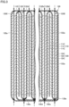
- Fig. 3 is a cross-sectional view of the electrode assembly 100. As illustrated in Fig. 3 , the electrode assembly 100 includes a plurality of electrodes 110 and 120, a separator 130, and an insulating film 140 (see Fig. 7 ).
- the plurality of electrodes 110 and 120 are arranged side by side in one direction (the lateral direction in Fig. 3 ).
- the plurality of electrodes 110 and 120 include a plurality of positive electrodes 110 and a plurality of negative electrodes 120.
- Each positive electrode 110 is formed in a rectangular shape elongated in a width direction (a direction orthogonal to both the one direction and the vertical direction).
- Each positive electrode 110 includes a positive electrode collector foil 112 and a positive electrode active material layer 114 provided on both surfaces of the positive electrode collector foil 112.
- the positive electrode collector foil 112 includes a positive electrode tab 112p on which the positive electrode active material layer 114 is not provided. The positive electrode tab 112p protrudes toward one side of the width direction (a direction orthogonal to the paper surface of Fig. 3 ).
- Each negative electrode 120 is formed in a rectangular shape elongated in the width direction.
- Each negative electrode 120 includes a negative electrode collector foil 122 and a negative electrode active material layer 124 provided on both surfaces of the negative electrode collector foil 122.
- the negative electrode collector foil 122 includes a negative electrode tab 122n on which the negative electrode active material layer 124 is not provided. The negative electrode tab 122n protrudes toward the other side of the width direction.
- the separator 130 insulates the positive electrode 110 and the negative electrode 120 from each other.
- the separator 130 is made of an insulating material, and has minute voids that allow ions to pass through. As illustrated in Fig. 3 , the separator 130 is formed in a zigzag shape.
- Fig. 4 is a plan view of the separator before being formed in a zigzag shape.
- the separator 130 has a rectangular shape before being formed in a zigzag shape.
- the separator 130 is formed in a zigzag shape and is arranged between the electrodes 110 and 120.
- the separator 130 includes a plurality of intervening portions 132a, a plurality of upper folded portions 132b, a plurality of lower folded portions 132c, and an outermost covering portion 132d.
- Each intervening portion 132a is interposed between a pair of electrodes 110 and 120 adjacent to each other in the one direction. In other words, each intervening portion 132a functions to insulate the positive electrode 110 and the negative electrode 120 from each other. Each intervening portion 132a is formed in a rectangular shape.
- Each upper folded portion 132b connects an upper end of one intervening portion 132a of the plurality of intervening portions 132a and an upper end of another intervening portion 132a of the plurality of intervening portions 132a which is adjacent to the one intervening portion 132a on one side of the one direction.
- the upper folded portion 132b is disposed above the positive electrode 110.
- Each lower folded portion 132c connects a lower end of one intervening portion 132a of the plurality of intervening portions 132a and a lower end of another intervening portion 132a of the plurality of intervening portions 132a which is adjacent to the one intervening portion 132a on the other side of the one direction.
- the lower folded portion 132c is disposed below the negative electrode 120.
- the negative electrode 120 is disposed above the lower folded portion 132c.
- Each of the lower folded portions 132c is connected to a lower end of the negative electrode 120, more specifically, a lower end of the negative electrode collector foil 122. Specifically, as indicated by arrows in Fig. 3 , heat is applied from the outside of the lower folded portion 132c to the lower folded portion 132c by laser irradiation or the like. Thereby, the lower folded portion 132c is connected (welded) to the lower end of the negative electrode collector foil 122.
- the outermost covering portion 132d collectively covers each upper folded portion 132b and each lower folded portion 132c. More specifically, the outermost covering portion 132d collectively covers all of the electrodes 110 and 120, all of the intervening portions 132a, all of the upper folded portions 132b and all of the lower folded portions 132c while being wound around a central axis parallel to the width direction.
- a terminal end 132e (see Figs. 3 and 4 ) of the outermost covering portion 132d is configured not to overlap with the positive electrode active material layer 114 and the negative electrode active material layer 124 in the one direction. In the present embodiment, the terminal end 132e of the outermost covering portion 132d is provided below each of the electrodes 110 and 120.
- the outermost covering portion 132d is connected to each lower folded portion 132c. Specifically, as indicated by an arrow in Fig. 3 , heat is applied to a portion of the outermost covering portion 132d overlapping with each lower folded portion 132c from the outside of this portion by laser irradiation or the like. Thereby, the outermost covering portion 132d is connected (welded) to each lower folded portion 132c. At this time, each lower folded portion 132c is connected (welded) to the lower end of the negative electrode collector foil 122.
- the outermost covering portion 132d is connected to each upper folded portion 132b. Specifically, as indicated by arrows in Fig. 3 , heat is applied to a portion of the outermost covering portion 132d overlapping with each upper folded portion 132b from the outside of this portion by laser irradiation or the like. Thereby, the outermost covering portion 132d is connected (welded) to each upper folded portion 132b.
- the plurality of negative electrodes 120 include an outermost negative electrode 120E disposed outermost in one direction.
- a lower end of the outermost negative electrode 120E is connected to the outermost covering portion 132d.
- An upper end of the outermost negative electrode 120E is connected to the outermost covering portion 132d.
- the lower end and the upper end of the outermost negative electrode 120E are connected to the outermost covering portion 132d by laser irradiation or the like in the same manner as described above.
- the upper end of the positive electrode 110 more specifically, the upper end of the positive electrode collector foil 112 may be connected to the upper folded portion 132b.
- the lower end of the positive electrode collector foil 112 may be connected to the outermost covering portion 132d.
- the insulating film 140 collectively covers the peripheral surface and bottom surface of the plurality of electrodes 110 and 120 and the separator 130. In Fig. 7 , the insulating film 140 is indicated by dots.
- the cell case 200 houses the electrode assembly 100.
- the cell case 200 contains an electrolytic solution (not illustrated).
- the cell case 200 is sealed.
- the cell case 200 includes a case body 210 and a lid 220.
- the case body 210 has an opening that opens upward.
- the case body 210 is made of a metal such as aluminum.
- the case body 210 includes a bottom wall 212 and a peripheral wall 214.
- the bottom wall 212 is formed in a rectangular flat plate shape.
- the peripheral wall 214 rises from the bottom wall 212.
- the peripheral wall 214 is formed in a quadrangular cylindrical shape.
- the length of the peripheral wall 214 in the width direction is longer than the length of the peripheral wall 214 in the thickness direction.
- the length of the peripheral wall 214 in the height direction is longer than the length of the peripheral wall 214 in the thickness direction.
- the lid 220 closes the opening of the case body 210.
- the lid 220 is connected to the opening by welding or the like.
- the lid 220 is formed in a flat plate shape.
- the lid 220 is made of a metal such as aluminum.
- the lid 220 includes a pressure release valve 222 and a sealing member 224.
- the pressure release valve 222 is formed at a central portion of the lid 220.
- the pressure release valve 222 is configured to break when the internal pressure of the cell case 200 becomes equal to or higher than a predetermined pressure. When the pressure release valve 222 is broken, the gas in the cell case 200 is released to the outside of the cell case 200 through the pressure release valve 222, which reduces the internal pressure of the cell case 200.
- the sealing member 224 seals a liquid injection port h formed on the lid 220.
- the liquid injection port h is a through hole for injecting an electrolytic solution into the cell case 200 in the manufacturing process of the power storage cell 1. After the electrolytic solution is injected into the case body 210 through the liquid injection port h, the liquid injection port h is sealed by the sealing member 224.
- the pair of external terminals 300 is fixed to the cell case 200.
- One of the pair of external terminals 300 is a positive external terminal, and the other is a negative external terminal.
- Each external terminal 300 is fixed to an upper surface of the lid 220 via an upper insulating portion 510 which will be described later.
- Each external terminal 300 is made of a metal such as aluminum.
- Each external terminal 300 is formed, for example, in a rectangular parallelepiped shape.
- a bus bar (not illustrated) is connected to each external terminal 300 by welding or the like.
- the pair of connecting members 400 connects a plurality of electrode tabs 112p and a plurality of electrode tabs 122n to the pair of external terminals 300, respectively. More specifically, one of the pair of connecting members 400 connects the plurality of positive electrode tabs 112p to the positive external terminal 300, and the other connecting member 400 connects the plurality of negative electrode tabs 122n to the negative external terminal 300. Since the pair of connecting members 400 have substantially the same structure, only one connecting member 400 will be described below.
- the connecting member 400 includes a collector tab 410, a subtab 420, and a connecting pin 430.
- the collector tab 410 has a side portion 412 and an upper portion 414.
- the side portion 412 is arranged on a side surface of the electrode assembly 100 in the width direction.
- the upper portion 414 is arranged on an upper surface of the electrode assembly 100.
- the upper portion 414 extends inward in the width direction from an upper end of the side portion 412.
- the subtab 420 connects the plurality of positive electrode tabs 112p to the collector tab 410.
- One end 422 of the subtab 420 is connected to the plurality of positive electrode tabs 112p by welding or the like, and the other end 424 of the subtab 420 is connected to the side portion 412 of the collector tab 410 by welding or the like.
- the connecting pin 430 connects the collector tab 410 to the external terminal 300.
- the connecting pin 430 connects the upper portion 414 to the external terminal 300. Specifically, the lower end of the connecting pin 430 is inserted into a through hole provided on the upper portion 414 and is connected to the upper portion 414 by welding or the like, and the upper end of the connecting pin 430 is inserted into a through hole provided on the external terminal 300 and is connected to the external terminal 300 by welding, caulking or the like.
- the insulating member 500 insulates the cell case 200 and the connecting member 400 from each other.
- the insulating member 500 includes an upper insulating portion 510, a lower insulating portion 520, an insulator 530, and an insulating plate 540.
- the upper insulating portion 510 is fixed to the upper surface of the lid 220.
- the upper insulating portion 510 is disposed between the lid 220 and the external terminal 300.
- the upper insulating portion 510 is provided with an insertion hole through which the connecting pin 430 is inserted.
- the lower insulating portion 520 is fixed to the lower surface of the lid 220.
- the lower insulating portion 520 is disposed between the lid 220, and the upper portion 414 and a lower portion of the connecting pin 430.
- the lower insulating portion 520 is provided with an insertion hole through which the connecting pin 430 is inserted.
- the insulator 530 is disposed between the connecting pin 430 and the lid 220.
- the insulator 530 is formed in a cylindrical shape, and is configured to surround the connecting pin 430.
- the insulating plate 540 is fixed to the lower surface of the upper portion 414.
- the insulating plate 540 is disposed on the electrode assembly 100.
- a through hole is formed in a portion of the insulating plate 540 located below the pressure release valve 222 and a portion of the insulating plate 540 located below the liquid injection port h.
- each electrode 110 and each electrode 120 are alternately disposed between a pair of intervening portions 132a.
- each lower folded portion 132c is connected (welded) to the outermost covering portion 132d
- the lower end of each negative electrode collector foils 122 is connected (welded) to each lower folded portion 132c
- each upper folded portion 132b is connected (welded) to the outermost covering portion 132d
- the lower end and the upper end of each outermost negative electrode 120E are connected (welded) to the outermost covering portion 132d.
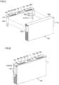
- one end 422 of the subtab 420 is connected to the plurality of electrode tabs 112p and 122n by welding or the like. Then, as indicated by arrows in Fig. 6 , one end 422 and the plurality of electrode tabs 112p and 122n are bent in such a manner that the end 422 of the subtab 420 is in contact with the side portion 412 of the collector tab 410.
- the electrode assembly 100 is inserted into the case body 210. Then, the lid 220 is welded to the case body 210 to close the opening.
- the electrolytic solution is supplied into the cell case 200 through the liquid injection port h, and the liquid injection port h is sealed with the sealing member 224.
- the separator 130 is formed in a zigzag shape and each lower folded portion 132c is connected to the negative electrode 120, at least the positional displacement of the negative electrode 120 with respect to the separator 130 is prevented.
- each lower folded portion 132c is connected to the outermost covering portion 132d, the relative displacement between the lower folded portions 132c is prevented.
- the positive electrode 110 is disposed in a space surrounded by a pair of the lower folded portion 132c and the upper folded portion 132b adjacent to each other, the positional displacement of the positive electrode 110 with respect to the separator 130 is further prevented.
- the negative electrode 120 is disposed above the lower folded portion 132c and the lower folded portion 132c is connected to the lower end of the negative electrode 120, but the positive electrode 110 may be disposed above the lower folded portion 132c and the lower folded portion 132c may be connected to the lower end of the positive electrode 110.
- each upper folded portion 132b may be connected to the upper end of each electrode 110 or 120.
- each lower folded portion 132c may not be connected to each electrode 110 or 120.
- the separator is formed in a zigzag shape and at least one of the upper folded portion and the lower folded portion is connected to the electrode, the positional displacement of the electrode with respect to the separator is prevented.
- the positional displacement of the negative electrode with respect to the separator is prevented.
- the positional displacement of the negative electrode with respect to the separator is more reliably prevented.
Landscapes
- Chemical & Material Sciences (AREA)
- Chemical Kinetics & Catalysis (AREA)
- Electrochemistry (AREA)
- General Chemical & Material Sciences (AREA)
- Engineering & Computer Science (AREA)
- Manufacturing & Machinery (AREA)
- Secondary Cells (AREA)
- Cell Separators (AREA)
- Electric Double-Layer Capacitors Or The Like (AREA)
- Connection Of Batteries Or Terminals (AREA)
Abstract
Description
- This non-provisional application is based on
Japanese Patent Application No. 2023-079353 filed on May 12, 2023 - The present disclosure relates to an electrode assembly.
-
Japanese Patent Laying-Open No. 2022-100813 - In the electrode assembly described in
Japanese Patent Laying-Open No. 2022-100813 - An object of the present disclosure is to provide an electrode assembly capable of preventing a positional displacement of an electrode with respect to a separator.
- According to an aspect of the present disclosure, there is provided an electrode assembly. The electrode assembly includes a plurality of electrodes arranged side by side in one direction, and a separator formed in a zigzag shape and configured to insulate the plurality of electrodes from each other. The separator includes a plurality of intervening portions, each of which is interposed between a pair of electrodes adjacent to each other in the one direction, an upper folded portion which connects an upper end of one intervening portion of the plurality of intervening portions and an upper end of another intervening portion of the plurality of intervening portions which is adjacent to the one intervening portion on one side of the one direction, and a lower folded portion which connects a lower end of the one intervening portion of the plurality of intervening portions and a lower end of another intervening portion of the plurality of intervening portions which is adjacent to the one intervening portion on the other side of the one direction. At least one of the upper folded portion and the lower folded portion is connected to the electrode.
- The foregoing and other objects, features, aspects and advantages of the present disclosure will become more apparent from the following detailed description of the present disclosure when taken in conjunction with the accompanying drawings.
-
-
Fig. 1 is a perspective view schematically illustrating a power storage cell according to an embodiment of the present disclosure; -
Fig. 2 is a cross-sectional view of the power storage cell illustrated inFig. 1 ; -
Fig. 3 is a cross-sectional view of an electrode assembly; -
Fig. 4 is a plan view of a separator before being formed in a zigzag shape; -
Fig. 5 is a perspective view schematically illustrating a step of connecting an electrode tab and a collector tab; -
Fig. 6 is a perspective view schematically illustrating a step of bending an electrode tab and a collector tab; and -
Fig. 7 is a perspective view schematically illustrating a step of inserting an electrode assembly into a case body. - Embodiments of the present disclosure will be described with reference to the drawings. In the following drawings, the same or corresponding members are denoted by the same reference numerals.
-
Fig. 1 is a perspective view schematically illustrating apower storage cell 1 according to an embodiment of the present disclosure.Fig. 2 is a cross-sectional view of thepower storage cell 1 illustrated inFig. 1 . - As illustrated in
Figs. 1 and2 , thepower storage cell 1 includes anelectrode assembly 100, acell case 200, an electrolytic solution (not illustrated), a pair ofexternal terminals 300, a pair of connectingmembers 400, and aninsulating member 500. -
Fig. 3 is a cross-sectional view of theelectrode assembly 100. As illustrated inFig. 3 , theelectrode assembly 100 includes a plurality ofelectrodes separator 130, and an insulating film 140 (seeFig. 7 ). - As illustrated in
Fig. 3 , the plurality ofelectrodes Fig. 3 ). The plurality ofelectrodes positive electrodes 110 and a plurality ofnegative electrodes 120. - Each
positive electrode 110 is formed in a rectangular shape elongated in a width direction (a direction orthogonal to both the one direction and the vertical direction). Eachpositive electrode 110 includes a positiveelectrode collector foil 112 and a positive electrodeactive material layer 114 provided on both surfaces of the positiveelectrode collector foil 112. As illustrated inFigs. 2 and5 , the positiveelectrode collector foil 112 includes apositive electrode tab 112p on which the positive electrodeactive material layer 114 is not provided. Thepositive electrode tab 112p protrudes toward one side of the width direction (a direction orthogonal to the paper surface ofFig. 3 ). - Each
negative electrode 120 is formed in a rectangular shape elongated in the width direction. Eachnegative electrode 120 includes a negative electrode collector foil 122 and a negative electrodeactive material layer 124 provided on both surfaces of the negative electrode collector foil 122. As illustrated inFigs. 2 and5 , the negative electrode collector foil 122 includes anegative electrode tab 122n on which the negative electrodeactive material layer 124 is not provided. Thenegative electrode tab 122n protrudes toward the other side of the width direction. - The
separator 130 insulates thepositive electrode 110 and thenegative electrode 120 from each other. Theseparator 130 is made of an insulating material, and has minute voids that allow ions to pass through. As illustrated inFig. 3 , theseparator 130 is formed in a zigzag shape. -
Fig. 4 is a plan view of the separator before being formed in a zigzag shape. As illustrated inFig. 4 , theseparator 130 has a rectangular shape before being formed in a zigzag shape. Theseparator 130 is formed in a zigzag shape and is arranged between theelectrodes separator 130 includes a plurality of interveningportions 132a, a plurality of upper foldedportions 132b, a plurality of lower foldedportions 132c, and anoutermost covering portion 132d. - Each intervening
portion 132a is interposed between a pair ofelectrodes portion 132a functions to insulate thepositive electrode 110 and thenegative electrode 120 from each other. Each interveningportion 132a is formed in a rectangular shape. - Each upper folded
portion 132b connects an upper end of one interveningportion 132a of the plurality of interveningportions 132a and an upper end of another interveningportion 132a of the plurality of interveningportions 132a which is adjacent to the one interveningportion 132a on one side of the one direction. In the present embodiment, the upper foldedportion 132b is disposed above thepositive electrode 110. - Each lower folded
portion 132c connects a lower end of one interveningportion 132a of the plurality of interveningportions 132a and a lower end of another interveningportion 132a of the plurality of interveningportions 132a which is adjacent to the one interveningportion 132a on the other side of the one direction. In the present embodiment, the lower foldedportion 132c is disposed below thenegative electrode 120. In other words, thenegative electrode 120 is disposed above the lower foldedportion 132c. - Each of the lower folded
portions 132c is connected to a lower end of thenegative electrode 120, more specifically, a lower end of the negative electrode collector foil 122. Specifically, as indicated by arrows inFig. 3 , heat is applied from the outside of the lower foldedportion 132c to the lower foldedportion 132c by laser irradiation or the like. Thereby, the lower foldedportion 132c is connected (welded) to the lower end of the negative electrode collector foil 122. - The outermost covering
portion 132d collectively covers each upper foldedportion 132b and each lower foldedportion 132c. More specifically, the outermost coveringportion 132d collectively covers all of theelectrodes portions 132a, all of the upper foldedportions 132b and all of the lower foldedportions 132c while being wound around a central axis parallel to the width direction. Aterminal end 132e (seeFigs. 3 and4 ) of the outermost coveringportion 132d is configured not to overlap with the positive electrodeactive material layer 114 and the negative electrodeactive material layer 124 in the one direction. In the present embodiment, theterminal end 132e of the outermost coveringportion 132d is provided below each of theelectrodes - As illustrated in
Fig. 3 , the outermost coveringportion 132d is connected to each lower foldedportion 132c. Specifically, as indicated by an arrow inFig. 3 , heat is applied to a portion of the outermost coveringportion 132d overlapping with each lower foldedportion 132c from the outside of this portion by laser irradiation or the like. Thereby, the outermost coveringportion 132d is connected (welded) to each lower foldedportion 132c. At this time, each lower foldedportion 132c is connected (welded) to the lower end of the negative electrode collector foil 122. - The
outermost covering portion 132d is connected to each upper foldedportion 132b. Specifically, as indicated by arrows inFig. 3 , heat is applied to a portion of theoutermost covering portion 132d overlapping with each upper foldedportion 132b from the outside of this portion by laser irradiation or the like. Thereby, theoutermost covering portion 132d is connected (welded) to each upper foldedportion 132b. - As illustrated in
Fig. 3 , the plurality ofnegative electrodes 120 include an outermostnegative electrode 120E disposed outermost in one direction. A lower end of the outermostnegative electrode 120E is connected to theoutermost covering portion 132d. An upper end of the outermostnegative electrode 120E is connected to theoutermost covering portion 132d. The lower end and the upper end of the outermostnegative electrode 120E are connected to theoutermost covering portion 132d by laser irradiation or the like in the same manner as described above. - The upper end of the
positive electrode 110, more specifically, the upper end of the positiveelectrode collector foil 112 may be connected to the upper foldedportion 132b. Similarly, the lower end of the positiveelectrode collector foil 112 may be connected to theoutermost covering portion 132d. - The insulating
film 140 collectively covers the peripheral surface and bottom surface of the plurality ofelectrodes separator 130. InFig. 7 , the insulatingfilm 140 is indicated by dots. - The
cell case 200 houses theelectrode assembly 100. Thecell case 200 contains an electrolytic solution (not illustrated). Thecell case 200 is sealed. Thecell case 200 includes acase body 210 and alid 220. - The
case body 210 has an opening that opens upward. Thecase body 210 is made of a metal such as aluminum. As illustrated inFig. 2 , thecase body 210 includes abottom wall 212 and aperipheral wall 214. Thebottom wall 212 is formed in a rectangular flat plate shape. Theperipheral wall 214 rises from thebottom wall 212. Theperipheral wall 214 is formed in a quadrangular cylindrical shape. The length of theperipheral wall 214 in the width direction is longer than the length of theperipheral wall 214 in the thickness direction. The length of theperipheral wall 214 in the height direction is longer than the length of theperipheral wall 214 in the thickness direction. - The
lid 220 closes the opening of thecase body 210. Thelid 220 is connected to the opening by welding or the like. Thelid 220 is formed in a flat plate shape. Thelid 220 is made of a metal such as aluminum. Thelid 220 includes apressure release valve 222 and a sealingmember 224. - The
pressure release valve 222 is formed at a central portion of thelid 220. Thepressure release valve 222 is configured to break when the internal pressure of thecell case 200 becomes equal to or higher than a predetermined pressure. When thepressure release valve 222 is broken, the gas in thecell case 200 is released to the outside of thecell case 200 through thepressure release valve 222, which reduces the internal pressure of thecell case 200. - The sealing
member 224 seals a liquid injection port h formed on thelid 220. The liquid injection port h is a through hole for injecting an electrolytic solution into thecell case 200 in the manufacturing process of thepower storage cell 1. After the electrolytic solution is injected into thecase body 210 through the liquid injection port h, the liquid injection port h is sealed by the sealingmember 224. - The pair of
external terminals 300 is fixed to thecell case 200. One of the pair ofexternal terminals 300 is a positive external terminal, and the other is a negative external terminal. Eachexternal terminal 300 is fixed to an upper surface of thelid 220 via an upper insulatingportion 510 which will be described later. Eachexternal terminal 300 is made of a metal such as aluminum. Eachexternal terminal 300 is formed, for example, in a rectangular parallelepiped shape. A bus bar (not illustrated) is connected to eachexternal terminal 300 by welding or the like. - The pair of connecting members 400 (see
Fig. 2 ) connects a plurality ofelectrode tabs 112p and a plurality ofelectrode tabs 122n to the pair ofexternal terminals 300, respectively. More specifically, one of the pair of connectingmembers 400 connects the plurality ofpositive electrode tabs 112p to the positiveexternal terminal 300, and the other connectingmember 400 connects the plurality ofnegative electrode tabs 122n to the negativeexternal terminal 300. Since the pair of connectingmembers 400 have substantially the same structure, only one connectingmember 400 will be described below. - The connecting
member 400 includes acollector tab 410, asubtab 420, and a connectingpin 430. - The
collector tab 410 has aside portion 412 and anupper portion 414. Theside portion 412 is arranged on a side surface of theelectrode assembly 100 in the width direction. Theupper portion 414 is arranged on an upper surface of theelectrode assembly 100. Theupper portion 414 extends inward in the width direction from an upper end of theside portion 412. - The
subtab 420 connects the plurality ofpositive electrode tabs 112p to thecollector tab 410. Oneend 422 of thesubtab 420 is connected to the plurality ofpositive electrode tabs 112p by welding or the like, and theother end 424 of thesubtab 420 is connected to theside portion 412 of thecollector tab 410 by welding or the like. - The connecting
pin 430 connects thecollector tab 410 to theexternal terminal 300. The connectingpin 430 connects theupper portion 414 to theexternal terminal 300. Specifically, the lower end of the connectingpin 430 is inserted into a through hole provided on theupper portion 414 and is connected to theupper portion 414 by welding or the like, and the upper end of the connectingpin 430 is inserted into a through hole provided on theexternal terminal 300 and is connected to theexternal terminal 300 by welding, caulking or the like. - The insulating
member 500 insulates thecell case 200 and the connectingmember 400 from each other. The insulatingmember 500 includes an upper insulatingportion 510, a lower insulatingportion 520, aninsulator 530, and an insulatingplate 540. - The upper insulating
portion 510 is fixed to the upper surface of thelid 220. The upper insulatingportion 510 is disposed between thelid 220 and theexternal terminal 300. The upper insulatingportion 510 is provided with an insertion hole through which the connectingpin 430 is inserted. - The lower insulating
portion 520 is fixed to the lower surface of thelid 220. The lower insulatingportion 520 is disposed between thelid 220, and theupper portion 414 and a lower portion of the connectingpin 430. The lower insulatingportion 520 is provided with an insertion hole through which the connectingpin 430 is inserted. - The
insulator 530 is disposed between the connectingpin 430 and thelid 220. Theinsulator 530 is formed in a cylindrical shape, and is configured to surround the connectingpin 430. - The insulating
plate 540 is fixed to the lower surface of theupper portion 414. The insulatingplate 540 is disposed on theelectrode assembly 100. A through hole is formed in a portion of the insulatingplate 540 located below thepressure release valve 222 and a portion of the insulatingplate 540 located below the liquid injection port h. - Next, a process of manufacturing the
power storage cell 1 will be described with reference toFigs. 5 to 7 . - First, while the
separator 130 is being formed in a zigzag shape, eachelectrode 110 and eachelectrode 120 are alternately disposed between a pair of interveningportions 132a. After winding theoutermost covering portion 132d of theseparator 130, by irradiating a laser beam from the outside of theoutermost covering portion 132d, for example, each lower foldedportion 132c is connected (welded) to theoutermost covering portion 132d, the lower end of each negative electrode collector foils 122 is connected (welded) to each lower foldedportion 132c, each upper foldedportion 132b is connected (welded) to theoutermost covering portion 132d, and the lower end and the upper end of each outermostnegative electrode 120E are connected (welded) to theoutermost covering portion 132d. - Next, as illustrated in
Fig. 5 , oneend 422 of thesubtab 420 is connected to the plurality ofelectrode tabs Fig. 6 , oneend 422 and the plurality ofelectrode tabs end 422 of thesubtab 420 is in contact with theside portion 412 of thecollector tab 410. - Subsequently, as illustrated in
Fig. 7 , after the peripheral surface and bottom surface of the plurality ofelectrodes separator 130 are collectively covered with the insulatingfilm 140, theelectrode assembly 100 is inserted into thecase body 210. Then, thelid 220 is welded to thecase body 210 to close the opening. - Thereafter, the electrolytic solution is supplied into the
cell case 200 through the liquid injection port h, and the liquid injection port h is sealed with the sealingmember 224. - As described above, in the
electrode assembly 100 according to the present embodiment, since theseparator 130 is formed in a zigzag shape and each lower foldedportion 132c is connected to thenegative electrode 120, at least the positional displacement of thenegative electrode 120 with respect to theseparator 130 is prevented. - Further, since each lower folded
portion 132c is connected to theoutermost covering portion 132d, the relative displacement between the lower foldedportions 132c is prevented. In addition, since thepositive electrode 110 is disposed in a space surrounded by a pair of the lower foldedportion 132c and the upper foldedportion 132b adjacent to each other, the positional displacement of thepositive electrode 110 with respect to theseparator 130 is further prevented. - In the above embodiment, the
negative electrode 120 is disposed above the lower foldedportion 132c and the lower foldedportion 132c is connected to the lower end of thenegative electrode 120, but thepositive electrode 110 may be disposed above the lower foldedportion 132c and the lower foldedportion 132c may be connected to the lower end of thepositive electrode 110. - Even in a case where either the
positive electrode 110 or thenegative electrode 120 is disposed above the lower foldedportion 132c, each upper foldedportion 132b may be connected to the upper end of eachelectrode portion 132c may not be connected to eachelectrode - It will be appreciated by those skilled in the art that the exemplary embodiments described above are specific examples of the following aspects.
-
- 1. An electrode assembly comprising:
- a plurality of electrodes arranged side by side in one direction;
- a separator formed in a zigzag shape and configured to insulate the plurality of electrodes from each other,
- wherein the separator includes:
- a plurality of intervening portions, each of which is interposed between a pair of electrodes adjacent to each other in the one direction;
- an upper folded portion which connects an upper end of one intervening portion of the plurality of intervening portions and an upper end of another intervening portion of the plurality of intervening portions which is adjacent to the one intervening portion on one side of the one direction; and
- a lower folded portion which connects a lower end of the one intervening portion of the plurality of intervening portions and a lower end of another intervening portion of the plurality of intervening portions which is adjacent to the one intervening portion on the other side of the one direction,
- at least one of the upper folded portion and the lower folded portion is connected to the electrode.
- In this electrode assembly, since the separator is formed in a zigzag shape and at least one of the upper folded portion and the lower folded portion is connected to the electrode, the positional displacement of the electrode with respect to the separator is prevented.
- The electrode assembly according to
aspect 1, wherein - the plurality of electrodes include a plurality of positive electrodes and a plurality of negative electrodes,
- the negative electrode is disposed above the lower folded portion, and
- the lower folded portion is connected to a lower end of the negative electrode.
- According to this aspect, the positional displacement of the negative electrode with respect to the separator is prevented.
- The electrode assembly according to
aspect 1 or 2, wherein - the separator further includes an outermost covering portion which collectively covers the upper folded portion and the lower folded portion, and
- the lower folded portion is connected to the outermost covering portion.
- According to this aspect, the relative displacement between the lower folded portions is prevented.
- The electrode assembly according to aspect 3, wherein
- the plurality of electrodes include a plurality of positive electrodes and a plurality of negative electrodes, and
- an upper end of the negative electrode is connected to the outermost covering portion.
- According to this aspect, the positional displacement of the negative electrode with respect to the separator is more reliably prevented.
- The electrode assembly according to aspect 3 or 4, wherein
the upper folded portion is connected to the outermost covering portion. - The electrode assembly according to any one of aspects 3 to 5, wherein
- the plurality of electrodes include a plurality of positive electrodes and a plurality of negative electrodes,
- the plurality of negative electrodes include an outermost negative electrode disposed outermost in the one direction, and
- a lower end of the outermost negative electrode is connected to the outermost covering portion.
- Although the present disclosure has been described and illustrated in detail, it is clearly understood that the same is by way of illustration and example only and is not to be taken by way of limitation, the scope of the present disclosure being interpreted by the terms of the appended claims.
Claims (6)
- An electrode assembly (100) comprising:a plurality of electrodes (110, 120) arranged side by side in one direction; anda separator (130) formed in a zigzag shape and configured to insulate the plurality of electrodes from each other,wherein the separator includes:a plurality of intervening portions (132a), each of which is interposed between a pair of electrodes adjacent to each other in the one direction;an upper folded portion (132b) which connects an upper end of one intervening portion of the plurality of intervening portions and an upper end of another intervening portion of the plurality of intervening portions which is adjacent to the one intervening portion on one side of the one direction; anda lower folded portion (132c) which connects a lower end of the one intervening portion of the plurality of intervening portions and a lower end of another intervening portion of the plurality of intervening portions which is adjacent to the one intervening portion on the other side of the one direction,at least one of the upper folded portion and the lower folded portion is connected to the electrode.
- The electrode assembly according to claim 1, whereinthe plurality of electrodes include a plurality of positive electrodes (110) and a plurality of negative electrodes (120),the negative electrode is disposed above the lower folded portion (132c), andthe lower folded portion is connected to a lower end of the negative electrode (120).
- The electrode assembly according to claim 1 or 2, whereinthe separator further includes an outermost covering portion (132d) which collectively covers the upper folded portion and the lower folded portion, andthe lower folded portion is connected to the outermost covering portion.
- The electrode assembly according to claim 3, whereinthe plurality of electrodes include a plurality of positive electrodes (110) and a plurality of negative electrodes (120), andan upper end of the negative electrode is connected to the outermost covering portion.
- The electrode assembly according to claim 3 or 4, wherein
the upper folded portion is connected to the outermost covering portion. - The electrode assembly according to any one of aspects 3 to 5, whereinthe plurality of electrodes include a plurality of positive electrodes (110) and a plurality of negative electrodes (120),the plurality of negative electrodes include an outermost negative electrode (120E) disposed outermost in the one direction, anda lower end of the outermost negative electrode is connected to the outermost covering portion.
Applications Claiming Priority (1)
| Application Number | Priority Date | Filing Date | Title |
|---|---|---|---|
| JP2023079353A JP7838517B2 (en) | 2023-05-12 | 2023-05-12 | electrode body |
Publications (2)
| Publication Number | Publication Date |
|---|---|
| EP4462533A1 true EP4462533A1 (en) | 2024-11-13 |
| EP4462533B1 EP4462533B1 (en) | 2025-08-06 |
Family
ID=90366405
Family Applications (1)
| Application Number | Title | Priority Date | Filing Date |
|---|---|---|---|
| EP24164042.4A Active EP4462533B1 (en) | 2023-05-12 | 2024-03-18 | Electrode assembly |
Country Status (5)
| Country | Link |
|---|---|
| US (1) | US20240379991A1 (en) |
| EP (1) | EP4462533B1 (en) |
| JP (1) | JP7838517B2 (en) |
| KR (1) | KR20240164406A (en) |
| CN (1) | CN118943452A (en) |
Citations (9)
| Publication number | Priority date | Publication date | Assignee | Title |
|---|---|---|---|---|
| JP2000251944A (en) * | 1998-09-17 | 2000-09-14 | Toshiba Corp | Non-aqueous electrolyte secondary battery and method of manufacturing non-aqueous electrolyte secondary battery |
| JP5408686B2 (en) * | 2008-03-11 | 2014-02-05 | Necエナジーデバイス株式会社 | Stacked battery |
| JP5678270B2 (en) * | 2010-07-23 | 2015-02-25 | エリーパワー株式会社 | Power generation element and secondary battery |
| US9318748B2 (en) * | 2011-04-26 | 2016-04-19 | Commissariat à l'énergie atomique et aux énergies alternatives | Bipolar electrochemical Li-ion battery having increased capacity |
| JP2019053818A (en) * | 2017-09-12 | 2019-04-04 | 株式会社Gsユアサ | Power storage element, and power storage device including the same |
| CN110521045A (en) * | 2017-12-01 | 2019-11-29 | 株式会社Lg化学 | Electrode assembly and battery including the same |
| JP2022100813A (en) | 2020-12-24 | 2022-07-06 | プライムプラネットエナジー&ソリューションズ株式会社 | Secondary battery |
| US20230013024A1 (en) * | 2021-07-09 | 2023-01-19 | Lg Energy Solution, Ltd. | Electrode Assembly |
| WO2023058955A1 (en) * | 2021-10-07 | 2023-04-13 | 주식회사 엘지에너지솔루션 | Electrode assembly and battery cell including same |
Family Cites Families (4)
| Publication number | Priority date | Publication date | Assignee | Title |
|---|---|---|---|---|
| JP6451077B2 (en) * | 2014-05-08 | 2019-01-16 | 日新電機株式会社 | Electric storage device and method for manufacturing electric storage device |
| JP7116905B2 (en) * | 2017-12-01 | 2022-08-12 | 株式会社Gsユアサ | Storage element |
| CN112117494A (en) * | 2020-10-09 | 2020-12-22 | 昆山聚创新能源科技有限公司 | Laminate, lamination method and application thereof |
| KR102769533B1 (en) * | 2021-06-16 | 2025-02-19 | 삼성에스디아이 주식회사 | Rechargeable secondary battery |
-
2023
- 2023-05-12 JP JP2023079353A patent/JP7838517B2/en active Active
-
2024
- 2024-03-18 EP EP24164042.4A patent/EP4462533B1/en active Active
- 2024-04-10 US US18/631,640 patent/US20240379991A1/en active Pending
- 2024-05-02 KR KR1020240058389A patent/KR20240164406A/en active Pending
- 2024-05-08 CN CN202410559976.6A patent/CN118943452A/en active Pending
Patent Citations (9)
| Publication number | Priority date | Publication date | Assignee | Title |
|---|---|---|---|---|
| JP2000251944A (en) * | 1998-09-17 | 2000-09-14 | Toshiba Corp | Non-aqueous electrolyte secondary battery and method of manufacturing non-aqueous electrolyte secondary battery |
| JP5408686B2 (en) * | 2008-03-11 | 2014-02-05 | Necエナジーデバイス株式会社 | Stacked battery |
| JP5678270B2 (en) * | 2010-07-23 | 2015-02-25 | エリーパワー株式会社 | Power generation element and secondary battery |
| US9318748B2 (en) * | 2011-04-26 | 2016-04-19 | Commissariat à l'énergie atomique et aux énergies alternatives | Bipolar electrochemical Li-ion battery having increased capacity |
| JP2019053818A (en) * | 2017-09-12 | 2019-04-04 | 株式会社Gsユアサ | Power storage element, and power storage device including the same |
| CN110521045A (en) * | 2017-12-01 | 2019-11-29 | 株式会社Lg化学 | Electrode assembly and battery including the same |
| JP2022100813A (en) | 2020-12-24 | 2022-07-06 | プライムプラネットエナジー&ソリューションズ株式会社 | Secondary battery |
| US20230013024A1 (en) * | 2021-07-09 | 2023-01-19 | Lg Energy Solution, Ltd. | Electrode Assembly |
| WO2023058955A1 (en) * | 2021-10-07 | 2023-04-13 | 주식회사 엘지에너지솔루션 | Electrode assembly and battery cell including same |
Also Published As
| Publication number | Publication date |
|---|---|
| KR20240164406A (en) | 2024-11-19 |
| JP2024163599A (en) | 2024-11-22 |
| JP7838517B2 (en) | 2026-04-01 |
| CN118943452A (en) | 2024-11-12 |
| EP4462533B1 (en) | 2025-08-06 |
| US20240379991A1 (en) | 2024-11-14 |
Similar Documents
| Publication | Publication Date | Title |
|---|---|---|
| CN100463286C (en) | secondary battery | |
| US9343726B2 (en) | Rechargeable battery | |
| EP3086382B1 (en) | Rechargeable battery | |
| EP4300700A1 (en) | Battery and method for manufacturing battery | |
| EP4462533A1 (en) | Electrode assembly | |
| CN113258215A (en) | Secondary battery | |
| EP4462534A1 (en) | Electrode assembly and power storage cell | |
| EP4462531A1 (en) | Power storage cell | |
| US20240421444A1 (en) | Power storage cell | |
| US20240396174A1 (en) | Power storage cell | |
| US20240396071A1 (en) | Method for manufacturing electrode assembly | |
| US20240421392A1 (en) | Power storage cell | |
| KR20230049336A (en) | Rechargeable-battery battery | |
| CN222088304U (en) | Electrode body | |
| US20240128559A1 (en) | Method of manufacturing power storage cell and power storage cell | |
| JP7810153B2 (en) | Energy storage module | |
| JP7768197B2 (en) | secondary battery | |
| CN221596713U (en) | Power storage unit | |
| EP4571805A1 (en) | Electricity storage device and method for manufacturing same | |
| US20250015397A1 (en) | Method of manufacturing battery case | |
| EP4432427A1 (en) | Power storage cell |
Legal Events
| Date | Code | Title | Description |
|---|---|---|---|
| PUAI | Public reference made under article 153(3) epc to a published international application that has entered the european phase |
Free format text: ORIGINAL CODE: 0009012 |
|
| STAA | Information on the status of an ep patent application or granted ep patent |
Free format text: STATUS: REQUEST FOR EXAMINATION WAS MADE |
|
| 17P | Request for examination filed |
Effective date: 20240318 |
|
| AK | Designated contracting states |
Kind code of ref document: A1 Designated state(s): AL AT BE BG CH CY CZ DE DK EE ES FI FR GB GR HR HU IE IS IT LI LT LU LV MC ME MK MT NL NO PL PT RO RS SE SI SK SM TR |
|
| GRAP | Despatch of communication of intention to grant a patent |
Free format text: ORIGINAL CODE: EPIDOSNIGR1 |
|
| STAA | Information on the status of an ep patent application or granted ep patent |
Free format text: STATUS: GRANT OF PATENT IS INTENDED |
|
| INTG | Intention to grant announced |
Effective date: 20250506 |
|
| GRAS | Grant fee paid |
Free format text: ORIGINAL CODE: EPIDOSNIGR3 |
|
| GRAA | (expected) grant |
Free format text: ORIGINAL CODE: 0009210 |
|
| STAA | Information on the status of an ep patent application or granted ep patent |
Free format text: STATUS: THE PATENT HAS BEEN GRANTED |
|
| AK | Designated contracting states |
Kind code of ref document: B1 Designated state(s): AL AT BE BG CH CY CZ DE DK EE ES FI FR GB GR HR HU IE IS IT LI LT LU LV MC ME MK MT NL NO PL PT RO RS SE SI SK SM TR |
|
| REG | Reference to a national code |
Ref country code: GB Ref legal event code: FG4D |
|
| REG | Reference to a national code |
Ref country code: CH Ref legal event code: EP |
|
| REG | Reference to a national code |
Ref country code: IE Ref legal event code: FG4D |
|
| REG | Reference to a national code |
Ref country code: DE Ref legal event code: R096 Ref document number: 602024000391 Country of ref document: DE |
|
| REG | Reference to a national code |
Ref country code: NL Ref legal event code: MP Effective date: 20250806 |
|
| PG25 | Lapsed in a contracting state [announced via postgrant information from national office to epo] |
Ref country code: IS Free format text: LAPSE BECAUSE OF FAILURE TO SUBMIT A TRANSLATION OF THE DESCRIPTION OR TO PAY THE FEE WITHIN THE PRESCRIBED TIME-LIMIT Effective date: 20251206 |
|
| PG25 | Lapsed in a contracting state [announced via postgrant information from national office to epo] |
Ref country code: NO Free format text: LAPSE BECAUSE OF FAILURE TO SUBMIT A TRANSLATION OF THE DESCRIPTION OR TO PAY THE FEE WITHIN THE PRESCRIBED TIME-LIMIT Effective date: 20251106 |
|
| REG | Reference to a national code |
Ref country code: LT Ref legal event code: MG9D |
|
| PG25 | Lapsed in a contracting state [announced via postgrant information from national office to epo] |
Ref country code: PT Free format text: LAPSE BECAUSE OF FAILURE TO SUBMIT A TRANSLATION OF THE DESCRIPTION OR TO PAY THE FEE WITHIN THE PRESCRIBED TIME-LIMIT Effective date: 20251209 |
|
| PG25 | Lapsed in a contracting state [announced via postgrant information from national office to epo] |
Ref country code: FI Free format text: LAPSE BECAUSE OF FAILURE TO SUBMIT A TRANSLATION OF THE DESCRIPTION OR TO PAY THE FEE WITHIN THE PRESCRIBED TIME-LIMIT Effective date: 20250806 |
|
| PG25 | Lapsed in a contracting state [announced via postgrant information from national office to epo] |
Ref country code: HR Free format text: LAPSE BECAUSE OF FAILURE TO SUBMIT A TRANSLATION OF THE DESCRIPTION OR TO PAY THE FEE WITHIN THE PRESCRIBED TIME-LIMIT Effective date: 20250806 Ref country code: NL Free format text: LAPSE BECAUSE OF FAILURE TO SUBMIT A TRANSLATION OF THE DESCRIPTION OR TO PAY THE FEE WITHIN THE PRESCRIBED TIME-LIMIT Effective date: 20250806 |
|
| PG25 | Lapsed in a contracting state [announced via postgrant information from national office to epo] |
Ref country code: GR Free format text: LAPSE BECAUSE OF FAILURE TO SUBMIT A TRANSLATION OF THE DESCRIPTION OR TO PAY THE FEE WITHIN THE PRESCRIBED TIME-LIMIT Effective date: 20251107 |
|
| PG25 | Lapsed in a contracting state [announced via postgrant information from national office to epo] |
Ref country code: SE Free format text: LAPSE BECAUSE OF FAILURE TO SUBMIT A TRANSLATION OF THE DESCRIPTION OR TO PAY THE FEE WITHIN THE PRESCRIBED TIME-LIMIT Effective date: 20250806 |
|
| PG25 | Lapsed in a contracting state [announced via postgrant information from national office to epo] |
Ref country code: LV Free format text: LAPSE BECAUSE OF FAILURE TO SUBMIT A TRANSLATION OF THE DESCRIPTION OR TO PAY THE FEE WITHIN THE PRESCRIBED TIME-LIMIT Effective date: 20250806 |
|
| PG25 | Lapsed in a contracting state [announced via postgrant information from national office to epo] |
Ref country code: BG Free format text: LAPSE BECAUSE OF FAILURE TO SUBMIT A TRANSLATION OF THE DESCRIPTION OR TO PAY THE FEE WITHIN THE PRESCRIBED TIME-LIMIT Effective date: 20250806 Ref country code: PL Free format text: LAPSE BECAUSE OF FAILURE TO SUBMIT A TRANSLATION OF THE DESCRIPTION OR TO PAY THE FEE WITHIN THE PRESCRIBED TIME-LIMIT Effective date: 20250806 |
|
| PG25 | Lapsed in a contracting state [announced via postgrant information from national office to epo] |
Ref country code: RS Free format text: LAPSE BECAUSE OF FAILURE TO SUBMIT A TRANSLATION OF THE DESCRIPTION OR TO PAY THE FEE WITHIN THE PRESCRIBED TIME-LIMIT Effective date: 20251106 |
|
| PG25 | Lapsed in a contracting state [announced via postgrant information from national office to epo] |
Ref country code: ES Free format text: LAPSE BECAUSE OF FAILURE TO SUBMIT A TRANSLATION OF THE DESCRIPTION OR TO PAY THE FEE WITHIN THE PRESCRIBED TIME-LIMIT Effective date: 20250806 |
|
| REG | Reference to a national code |
Ref country code: AT Ref legal event code: MK05 Ref document number: 1823022 Country of ref document: AT Kind code of ref document: T Effective date: 20250806 |
|
| PG25 | Lapsed in a contracting state [announced via postgrant information from national office to epo] |
Ref country code: SM Free format text: LAPSE BECAUSE OF FAILURE TO SUBMIT A TRANSLATION OF THE DESCRIPTION OR TO PAY THE FEE WITHIN THE PRESCRIBED TIME-LIMIT Effective date: 20250806 |
|
| PG25 | Lapsed in a contracting state [announced via postgrant information from national office to epo] |
Ref country code: DK Free format text: LAPSE BECAUSE OF FAILURE TO SUBMIT A TRANSLATION OF THE DESCRIPTION OR TO PAY THE FEE WITHIN THE PRESCRIBED TIME-LIMIT Effective date: 20250806 |
|
| PGFP | Annual fee paid to national office [announced via postgrant information from national office to epo] |
Ref country code: DE Payment date: 20260128 Year of fee payment: 3 |
|
| PG25 | Lapsed in a contracting state [announced via postgrant information from national office to epo] |
Ref country code: AT Free format text: LAPSE BECAUSE OF FAILURE TO SUBMIT A TRANSLATION OF THE DESCRIPTION OR TO PAY THE FEE WITHIN THE PRESCRIBED TIME-LIMIT Effective date: 20250806 |
|
| PG25 | Lapsed in a contracting state [announced via postgrant information from national office to epo] |
Ref country code: IT Free format text: LAPSE BECAUSE OF FAILURE TO SUBMIT A TRANSLATION OF THE DESCRIPTION OR TO PAY THE FEE WITHIN THE PRESCRIBED TIME-LIMIT Effective date: 20250806 |
|
| PGFP | Annual fee paid to national office [announced via postgrant information from national office to epo] |
Ref country code: FR Payment date: 20260209 Year of fee payment: 3 |
|
| PG25 | Lapsed in a contracting state [announced via postgrant information from national office to epo] |
Ref country code: CZ Free format text: LAPSE BECAUSE OF FAILURE TO SUBMIT A TRANSLATION OF THE DESCRIPTION OR TO PAY THE FEE WITHIN THE PRESCRIBED TIME-LIMIT Effective date: 20250806 |
|
| PG25 | Lapsed in a contracting state [announced via postgrant information from national office to epo] |
Ref country code: EE Free format text: LAPSE BECAUSE OF FAILURE TO SUBMIT A TRANSLATION OF THE DESCRIPTION OR TO PAY THE FEE WITHIN THE PRESCRIBED TIME-LIMIT Effective date: 20250806 Ref country code: SK Free format text: LAPSE BECAUSE OF FAILURE TO SUBMIT A TRANSLATION OF THE DESCRIPTION OR TO PAY THE FEE WITHIN THE PRESCRIBED TIME-LIMIT Effective date: 20250806 |