EP4462530A1 - Electrode connection device - Google Patents
Electrode connection device Download PDFInfo
- Publication number
- EP4462530A1 EP4462530A1 EP23737395.6A EP23737395A EP4462530A1 EP 4462530 A1 EP4462530 A1 EP 4462530A1 EP 23737395 A EP23737395 A EP 23737395A EP 4462530 A1 EP4462530 A1 EP 4462530A1
- Authority
- EP
- European Patent Office
- Prior art keywords
- electrode
- target region
- connection target
- connection
- seating
- Prior art date
- Legal status (The legal status is an assumption and is not a legal conclusion. Google has not performed a legal analysis and makes no representation as to the accuracy of the status listed.)
- Pending
Links
Images


Classifications
-
- H—ELECTRICITY
- H01—ELECTRIC ELEMENTS
- H01M—PROCESSES OR MEANS, e.g. BATTERIES, FOR THE DIRECT CONVERSION OF CHEMICAL ENERGY INTO ELECTRICAL ENERGY
- H01M10/00—Secondary cells; Manufacture thereof
- H01M10/04—Construction or manufacture in general
-
- H—ELECTRICITY
- H01—ELECTRIC ELEMENTS
- H01M—PROCESSES OR MEANS, e.g. BATTERIES, FOR THE DIRECT CONVERSION OF CHEMICAL ENERGY INTO ELECTRICAL ENERGY
- H01M10/00—Secondary cells; Manufacture thereof
- H01M10/04—Construction or manufacture in general
- H01M10/0404—Machines for assembling batteries
-
- B—PERFORMING OPERATIONS; TRANSPORTING
- B65—CONVEYING; PACKING; STORING; HANDLING THIN OR FILAMENTARY MATERIAL
- B65H—HANDLING THIN OR FILAMENTARY MATERIAL, e.g. SHEETS, WEBS, CABLES
- B65H19/00—Changing the web roll
- B65H19/10—Changing the web roll in unwinding mechanisms or in connection with unwinding operations
- B65H19/18—Attaching, e.g. pasting, the replacement web to the expiring web
-
- B—PERFORMING OPERATIONS; TRANSPORTING
- B65—CONVEYING; PACKING; STORING; HANDLING THIN OR FILAMENTARY MATERIAL
- B65H—HANDLING THIN OR FILAMENTARY MATERIAL, e.g. SHEETS, WEBS, CABLES
- B65H19/00—Changing the web roll
- B65H19/10—Changing the web roll in unwinding mechanisms or in connection with unwinding operations
- B65H19/18—Attaching, e.g. pasting, the replacement web to the expiring web
- B65H19/1842—Attaching, e.g. pasting, the replacement web to the expiring web standing splicing, i.e. the expiring web being stationary during splicing contact
- B65H19/1852—Attaching, e.g. pasting, the replacement web to the expiring web standing splicing, i.e. the expiring web being stationary during splicing contact taking place at a distance from the replacement roll
-
- B—PERFORMING OPERATIONS; TRANSPORTING
- B65—CONVEYING; PACKING; STORING; HANDLING THIN OR FILAMENTARY MATERIAL
- B65H—HANDLING THIN OR FILAMENTARY MATERIAL, e.g. SHEETS, WEBS, CABLES
- B65H19/00—Changing the web roll
- B65H19/10—Changing the web roll in unwinding mechanisms or in connection with unwinding operations
- B65H19/18—Attaching, e.g. pasting, the replacement web to the expiring web
- B65H19/1857—Support arrangement of web rolls
- B65H19/1873—Support arrangement of web rolls with two stationary roll supports carrying alternately the replacement and the expiring roll
-
- B—PERFORMING OPERATIONS; TRANSPORTING
- B65—CONVEYING; PACKING; STORING; HANDLING THIN OR FILAMENTARY MATERIAL
- B65H—HANDLING THIN OR FILAMENTARY MATERIAL, e.g. SHEETS, WEBS, CABLES
- B65H23/00—Registering, tensioning, smoothing or guiding webs
- B65H23/02—Registering, tensioning, smoothing or guiding webs transversely
- B65H23/032—Controlling transverse register of web
- B65H23/0326—Controlling transverse register of web by moving the unwinding device
-
- B—PERFORMING OPERATIONS; TRANSPORTING
- B65—CONVEYING; PACKING; STORING; HANDLING THIN OR FILAMENTARY MATERIAL
- B65H—HANDLING THIN OR FILAMENTARY MATERIAL, e.g. SHEETS, WEBS, CABLES
- B65H2405/00—Parts for holding the handled material
- B65H2405/40—Holders, supports for rolls
- B65H2405/42—Supports for rolls fully removable from the handling machine
- B65H2405/422—Trolley, cart, i.e. support movable on floor
- B65H2405/4222—Carts with full reels placed laterally one beside the other
-
- B—PERFORMING OPERATIONS; TRANSPORTING
- B65—CONVEYING; PACKING; STORING; HANDLING THIN OR FILAMENTARY MATERIAL
- B65H—HANDLING THIN OR FILAMENTARY MATERIAL, e.g. SHEETS, WEBS, CABLES
- B65H2553/00—Sensing or detecting means
- B65H2553/40—Sensing or detecting means using optical, e.g. photographic, elements
- B65H2553/42—Cameras
-
- B—PERFORMING OPERATIONS; TRANSPORTING
- B65—CONVEYING; PACKING; STORING; HANDLING THIN OR FILAMENTARY MATERIAL
- B65H—HANDLING THIN OR FILAMENTARY MATERIAL, e.g. SHEETS, WEBS, CABLES
- B65H2555/00—Actuating means
- B65H2555/20—Actuating means angular
- B65H2555/24—Servomotors
-
- B—PERFORMING OPERATIONS; TRANSPORTING
- B65—CONVEYING; PACKING; STORING; HANDLING THIN OR FILAMENTARY MATERIAL
- B65H—HANDLING THIN OR FILAMENTARY MATERIAL, e.g. SHEETS, WEBS, CABLES
- B65H2701/00—Handled material; Storage means
- B65H2701/10—Handled articles or webs
- B65H2701/19—Specific article or web
-
- B—PERFORMING OPERATIONS; TRANSPORTING
- B65—CONVEYING; PACKING; STORING; HANDLING THIN OR FILAMENTARY MATERIAL
- B65H—HANDLING THIN OR FILAMENTARY MATERIAL, e.g. SHEETS, WEBS, CABLES
- B65H2801/00—Application field
- B65H2801/72—Fuel cell manufacture
-
- Y—GENERAL TAGGING OF NEW TECHNOLOGICAL DEVELOPMENTS; GENERAL TAGGING OF CROSS-SECTIONAL TECHNOLOGIES SPANNING OVER SEVERAL SECTIONS OF THE IPC; TECHNICAL SUBJECTS COVERED BY FORMER USPC CROSS-REFERENCE ART COLLECTIONS [XRACs] AND DIGESTS
- Y02—TECHNOLOGIES OR APPLICATIONS FOR MITIGATION OR ADAPTATION AGAINST CLIMATE CHANGE
- Y02E—REDUCTION OF GREENHOUSE GAS [GHG] EMISSIONS, RELATED TO ENERGY GENERATION, TRANSMISSION OR DISTRIBUTION
- Y02E60/00—Enabling technologies; Technologies with a potential or indirect contribution to GHG emissions mitigation
- Y02E60/10—Energy storage using batteries
Definitions
- the present application relates to an electrode connection device and an electrode connection method using the same.
- a secondary battery refers to a battery capable of converting chemical energy into electrical energy to emit it, and conversely, storing it again in the form of chemical energy when the electrical energy is supplied in a discharged state, that is, a battery capable of alternately repeating charging and discharging.
- the secondary batteries are commonly referred to as storage batteries or accumulators because they can store electrical energy, and the currently widely-used secondary batteries include lead-acid batteries using sulfuric acid as an electrolyte, nickel-hydrogen batteries using potassium hydroxide as an electrolyte, lithium-ion batteries using a lithium salt solution as an electrolyte, and the like.
- Such a secondary battery is manufactured through an electrode process, an assembly process, and an activation process.
- a notching process, a lamination process, a stacking and folding process, and a packaging process are sequentially performed.
- various sensors such as an EPC (Edge Position Control) sensor have been disposed between the traveling electrode supply part and the traveling electrode seating part to confirm an alignment state of the traveling electrode, that is, the meandering degree of the traveling electrode line, and the traveling electrode supply part has been moved to the Y-axis to align the waiting electrode and the traveling electrode.
- EPC Edge Position Control
- the EPC sensor is located between the traveling electrode seating part and the traveling electrode supply part to check the Y-axis meandering of the traveling electrode, so that when the electrode from the position of the EPC sensor up to the traveling electrode seating part is not positioned on a straight line, there has been a problem that the waiting electrode and the traveling electrode are not aligned when the electrodes are connected.
- the electrode connection device of the present application comprises: a first electrode supply part supplying a first electrode; a second electrode supply part supplying a second electrode replacing the first electrode to the first electrode supply part when the supply of the first electrode is exhausted below a certain level; a photographing part photographing images of a connection target region of the first electrode and a connection target region of the second electrode; an aligning part aligning the connection target region of the first electrode and the connection target region of the second electrode based on the photographed images; and a connection part connecting the aligned connection target regions of the first and second electrodes.
- connection target regions of the first and second electrodes may each comprise a patterned portion and an unpatterned portion
- the photographing part may photograph images of a first boundary area between the patterned portion and the unpatterned portion of the first electrode and a second boundary area between the patterned portion and the unpatterned portion of the second electrode.
- the aligning part may adjust the positions of the first and second electrodes so that the first boundary area and the second boundary area are placed on the same line.
- the aligning part may comprise: a first electrode seating part having a first seating surface on which the connection target region of the first electrode is seated; a second electrode seating part disposed apart from the first electrode seating part by a predetermined interval and having a second seating surface on which the connection target region of the second electrode is seated and which is disposed to face the first seating surface; and a position adjustment part adjusting positions of the first and second electrode seating parts.
- the photographing part may comprise: a prism mirror positioned in a gap between the first electrode seating part and the second electrode seating part; a first light source part for irradiating the prism mirror with light to irradiate the connection target region of the first electrode with the reflected light; a second light source part for irradiating the prism mirror with light to irradiate the connection target region of the second electrode with the reflected light; and a camera simultaneously photographing the connection target regions of the first and second electrodes irradiated with the reflected light.
- the first seating surface comprises a first adsorption area adsorbing the connection target region of the first electrode and a non-adsorption area
- the second seating surface comprises a second adsorption area adsorbing the connection target region of the second electrode, wherein in a state where the first seating surface and the second seating surface are in contact with each other, the non-adsorption area and the second absorption area may be formed at positions corresponding to each other.
- it may comprise a cutting part that when the supply of the first electrode is exhausted below a certain level, the first electrode is cut along a preset cutting line to form the connection target region of the first electrode.
- connection target region of the first electrode formed after cutting may be adsorbed to the first adsorption area.
- the cut portion of the adsorbed connection target region of the first electrode may be positioned in the boundary area between the first adsorption area and the non-adsorption area in the first seating surface.
- connection part may move the first and second electrode seating parts so that the first and second seating surfaces come into close contact with each other.
- connection target region of the first electrode and the connection target region of the second electrode may be connected via an adhesive member while the first and second seating surfaces come in close contact with each other.
- first and second electrodes may be positive electrodes or negative electrodes equally.
- the electrode connection method using the above-described electrode connection device comprises steps of: photographing images of the connection target region of the first electrode and the connection target region of the second electrode for replacing the first electrode; aligning the connection target region of the first electrode and the connection target region of the second electrode based on the photographed images; and connecting the aligned connection target regions of the first and second electrodes.
- the electrode connection method of the present application uses the electrode connection device.
- the present application relates to an electrode connection device and an electrode connection method using the same.
- the electrode connection device of the present application and the electrode connection method using the same can suppress breakage occurrences, and thus exhibit excellent operation rates and yields, by accurately aligning the electrodes without distortion.
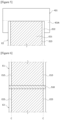
- Figure 1 is a diagram illustratively showing an electrode connection device according to one example of the present application
- Figure 2 is an exemplary diagram showing in detail a constitution of an aligning part of an electrode connection device according to one example of the present application
- Figure 3 is a diagram illustratively showing a first electrode seating part, a second electrode seating part, and a photographing part of an electrode connection device according to one example of the present application
- Figure 4 is a diagram illustratively showing a state, in which a first electrode is seated on a first seating surface, according to one example of the present application
- Figure 5 is a diagram illustratively showing a state, in which a second electrode is seated on a second seating surface, according to one example of the present application
- Figure 6 is a diagram illustratively showing a state where the aligned first and second electrodes are connected.
- the electrode connection device of the present application comprises a first electrode supply part (100), a second electrode supply part (200), a photographing part (300), an aligning part (400), and a connection part (500).
- the first electrode supply part (100) supplies the first electrode (E1).
- the first electrode (E1) may be a traveling electrode.
- the first electrode supply part (100) may comprise a first winding roll (110) on which the first electrode (E1) is wound and a first unwinding part (120) unwinding the first electrode (E1).
- the first unwinding part (120) may comprise a drive servomotor, and may be operated in a jog mode to unwind the first electrode (E1) to the first electrode seating part (410) to be described below.
- the second electrode supply part (200) supplies the second electrode (E2) replacing the first electrode (E1) to the first electrode supply part (100) when the supply of the first electrode (E1) is exhausted below a certain level.
- the second electrode supply part (200) may comprise a second winding roll (210) on which the second electrode (E2) is wound and a second unwinding part (220) unwinding the second electrode (E2).
- the second unwinding part (220) may comprise a drive servomotor, and may be operated in a jog mode to unwind the second electrode (E2) to the second electrode seating part (420) to be described below.
- the second electrode (E2) may be a waiting electrode.
- the traveling electrode means an electrode that is unwound and used earlier than the waiting electrode.
- the waiting electrode means an electrode which is connected to the traveling electrode and waits to automatically be replaceable therewith immediately, when the traveling electrode is unwound and exhausted.
- the photographing part (300) photographs images of the connection target region to the first electrode (E1) and the connection target region to the second electrode (E2).
- the connection target regions of the first and second electrodes (E2) may be the ends to be unwound, but are not limited thereto, and if the cutting is made during unwinding, the cut portion may be the connection target region.
- a detailed description of the aligning method will be described below.
- the aligning part (400) aligns the connection target region of the first electrode (E1) and the connection target region of the second electrode (E2) based on the photographed images. As the aligning part (400) aligns the connection target regions of the first electrode (E1) and the second electrode (E2) based on the photographed images, hereinafter, it is possible to prevent the distortion of the electrodes during the connection process of the connecting part (500).
- the connection part (500) connects the connection target regions of the aligned first and second electrodes (E1, E2). As the connection part (500) connects the connection target regions of the first and second electrodes (E1, E2), the first electrode (E1) supplied from the first electrode supply part (100) and exhausted may be replaced with the second electrode (E2). That is, after the first electrode (E1) is exhausted in the first electrode supply part (100), the second electrode (E2) connected to the first electrode (E1) may be supplied.
- connection target regions of the first and second electrodes (E1, E2) are photographed in advance prior to connecting the first and second electrodes (E1, E2), and the connection target regions of the first and second electrodes (E1, E2) are aligned based on the photographed images, so that it is possible to accurately connect the electrodes without distortion therebetween during the connection process, whereby the breakage occurrences can be suppressed while the electrodes are continuously supplied, and thus excellent operation rates and yields can be exhibited.
- connection target regions of the first and second electrodes (E1, E2) may each comprise patterned portions (E11, E21) and unpatterned portions (E12, E22), and the photographing part (300) may photograph images of a first boundary area (E13) between the patterned portion (E11) and the unpatterned portion (E12) of the first electrode and a second boundary area (E23) between the patterned portion (E21) and the unpatterned portion (E22) of the second electrode (E2).
- the first boundary area (E13) may be a boundary line between the patterned portion (E11) and the unpatterned portion (E12) formed along the longitudinal direction (or unwinding direction) of the first electrode (E1).
- the second boundary area (E23) may also be a boundary line between the patterned portion (E21) and the unpatterned portion (E22) formed along the longitudinal direction (or unwinding direction) of the second electrode (E2).
- the alignment state may mean a state where the first and second boundary areas (E13, E23) coincide, and the coincident first and second boundary areas (E13, E23) are placed on the same line (C) (see Figure 6 ).
- the patterned portion means a portion coated with a slurry representing polarity on a current collector included in an electrode
- the unpatterned portion means a portion where an electrode tab, which is a passage through which current flows, is formed on the current collector without the slurry being coated on the current collector.
- the aligning part (400) may adjust the positions of the first and second electrodes (E1, E2) so that the first boundary area (E13) and the second boundary area (E23) are placed on the same line (C).
- the position adjustment of the first and second electrodes (E1, E2) may be achieved by the position adjustment of the first and second seating parts (410, 420) to be described below.
- the aligning part (400) may comprise a first electrode seating part (410) having a first seating surface (411) on which the connection target region of the first electrode (E1) is seated, a second electrode seating part (420) disposed apart from the first electrode seating part (410) by a predetermined interval (P), and having a second seating surface (421) on which the connection target region of the second electrode (E2) is seated and which is disposed to face the first seating surface (411), and a position adjustment part (430) adjusting the positions of the first and second electrode seating parts (410, 420).
- the position adjustment part (430) is also referred to as a driving part or a moving part.
- the position adjustment part (430) may adjust the positions of the first and second electrode seating parts (410, 420) so that the first and second boundary areas (E13, E23) are placed on the same line (C).
- the first electrode (E1) is unwound from the first winding roll (110), whereby the connection target region may be seated on the first seating surface (411), and the second electrode (E2) is unwound from the second winding roll (210), whereby the connection target region may be seated on the second seating surface (421).
- the photographing part (300) is disposed in the interval (P) between the first electrode seating part (410) and the second electrode seating part (420), or between the first seating surface (411) and the second seating surface (421), and may be provided to be movable along the width (W) direction of the electrode.
- a moving rail (440) on which the photographing part (300) moves may be provided in the interval (P) between the first electrode seating part (410) and the second electrode seating part (420), or between the first seating surface (411) and the second seating surface (421).
- the aligning part (400) may check the alignment state of the connection target regions of the first and second electrodes (E1, E2) through the photographed images; when the distortion between the connection target regions of the first and second electrodes (E1, E2), for example, the first boundary area (E13) and the second boundary area (E23) occurs, it may adjust the positions of the first and second electrode seating parts (410, 420) through the position adjustment part (430) and control for the connection target regions of the first and second electrodes (E1, E2), for example, the first boundary area (E13) and the second boundary area (E23) to be aligned; and in the process of connecting the second electrodes (E1, E2), it may accurately connect the electrodes without any distortion therewith, so that it is possible to suppress breakage occurrences, and thus to exhibit excellent operation rates and yields.
- the photographing part (300) may comprise a prism mirror (310) positioned at the interval (P) between the first electrode seating part (410) and the second electrode seating part (420); a first light source part (320) for irradiating the prism mirror (310) with light to irradiate the connection target region of the first electrode (E1) with the reflected light; a second light source part (330) for irradiating the prism mirror with light to irradiate the connection target region of the second electrode (E2) with the reflected light; and a camera (340) simultaneously photographing the connection target regions of the first and second electrodes (E1, E2) irradiated with the reflected light.
- a prism mirror (310) positioned at the interval (P) between the first electrode seating part (410) and the second electrode seating part (420)
- a first light source part (320) for irradiating the prism mirror (310) with light to irradiate the connection target region of the first electrode (E1) with the reflected light
- the photographing part (300) according to the present invention can simultaneously check the alignment states of the connection target regions of the first and second electrodes (E1, E2) through the prism mirror (310), it is possible to know the more accurate alignment states.
- different areas can be simultaneously photographed with a single photographing device, there is an advantage of simplifying the equipment.
- the camera (340) may be a vision camera capable of photographing the light refracted by the prism mirror (310), and may perform photographing by a trigger signal.
- the camera (340) may be disposed at the above-described position to photograph the light refracted by the prism mirror (310), whereby it is possible to accurately check the alignment states of the first and second electrodes (E1, E2).
- the first seating surface (411) comprises a first adsorption area (411A) adsorbing the connection target region of the first electrode (E1) and a non-adsorption area (411B), and the second seating surface (421) comprises a second adsorption area (421A) adsorbing the connection target region of the second electrode (E2), wherein in a state where the first seating surface (411) and the second seating surface (421) are in contact with each other, the non-adsorption area (411B) and the second adsorption area (421A) may be formed at positions corresponding to each other.
- the first adsorption area (411A) When the first seating surface (411) has been bisected in the height direction, the first adsorption area (411A) may be located on the upper part and the non-adsorption area (411B) may be located on the lower part. Also, when the second seating surface (421) has been bisected in the height direction, the second adsorption area (421A) may be located on the lower part.
- the first and second adsorption areas (411A, 421A) may adsorb the connection target regions of the electrodes using an ejector or the like.
- it may comprise a cutting part (600) that when the supply of the first electrode (E1) is exhausted below a certain level, the first electrode (E1) is cut along a preset cutting line to form the connection target region of the first electrode (E1).
- the cutting line may be formed along the width (W) direction of the electrode.
- the cutting part (600) may use a knife or laser equipment, and the like, but is not particularly limited.
- the connection target region of the first electrode (E1) and the connection target region of the second electrode (E2) as cut and formed above may be connected. Meanwhile, the connection target region of the second electrode (E1) may be one pre-cut and formed through a separate cutting device.
- connection target region of the first electrode (E1) formed after cutting may be adsorbed to the first adsorption area (411A).
- the connection target regions that the first electrode (E1) and the second electrode (E2) are each cut and formed may be aligned and then connected.
- the cut portion (S) of the adsorbed connection target region of the first electrode (E1) may be positioned in the boundary area between the first adsorption area (411A) and the non-adsorption area (411B) in the first seating surface (411).
- connection target region of the first electrode (E1) located in the first adsorption area (411A) and the connection target region of the second electrode (E2) located in the second adsorption area (421A) may be connected, and in a state where the first seating surface (411) ) and the second seating surface (421) are in contact with each other, it may be advantageous when considering the connectivity between the first and second electrodes (E1, E2) that there is no gap in the boundary area between the connection target region of the first electrode (E1) and the connection target region of the second electrode (E2) which are adjacent to each other if possible.
- connection part (500) may move the first and second electrode seating parts (410, 420) so that the first and second seating surfaces (411, 421) come into close contact with each other.
- the connection part (500) may move the first and second electrode seating parts (410, 420) through the above-described position adjustment part (430), or may move the first and second electrode seating parts (410, 420) through a separate drive part.
- connection target region of the first electrode (E1) and the connection target region of the second electrode (E2) may be connected via an adhesive member (510) while the first and second seating surfaces (411, 412) come in close contact with each other.
- the adhesive member (510) may be, for example, a paper tape.
- connection part (500) when the first and second seating surfaces (411, 412) are in close contact with each other by the connection part (500) in a state where some regions of the adhesive member (510) are bonded to the connection target region of the first electrode (E1) seated on the first seating surface (411), other regions of the adhesive member (510) that are not bonded to the connection target region of the first electrode (E1) are bonded to the connection target region of the second electrode (E2) seated on the second seating surface (421), so that the connection target regions of the first and second electrodes (E1, E2) may be connected to each other.
- connection part (500) when the first and second seating surfaces (411, 412) are in close contact with each other by the connection part (500) in a state where some regions of the adhesive member (510) are bonded to the connection target region of the second electrode (E2) seated on the second seating surface (421), other regions of the adhesive member (510) that are not bonded to the connection target region of the second electrode (E2) are bonded to the connection target region of the first electrode (E1) seated on the first seating surface (411), so that the connection target regions of the first and second electrodes (E1, E2) may be connected to each other.
- the first and second electrodes (E1, E2) may be positive electrodes or negative electrodes equally.
- the first and second electrodes (E1, E2) may be positive electrodes, or the first and second electrodes (E1, E2) may be negative electrodes.
- the first and second electrodes (E1, E2) are composed of electrodes having the same polarity, the supply of the first electrode (E1) is exhausted, and then it is possible to be replaceable with the second electrode (E2).
- the present application also relates to an electrode connection method.
- An exemplary electrode connection method uses the above-described electrode connection device. Therefore, to the details of the electrode connection method to be described below, the contents described in the electrode connection device can be applied equally, so that they will be omitted.
- the electrode connection method of the present application uses the electrode connection device, and comprises steps of: photographing images of the connection target region of the first electrode (E1) and the connection target region of the second electrode (E2); aligning the connection target region of the first electrode (E1) and the connection target region of the second electrode (E2) based on the photographed images; and connecting the aligned connection target regions of the first and second electrodes (E1, E2).
- the electrode connection method of the present application are accurately aligned without the distortion between the electrodes in the connecting process by photographing the images in advance prior to connecting the connection target regions of the first and second electrodes (E1, E2), and aligning them based on the photographed images, so that the breakage occurrences can be suppressed, and thus excellent operation rates and yields can be exhibited.
Landscapes
- Engineering & Computer Science (AREA)
- Manufacturing & Machinery (AREA)
- Chemical & Material Sciences (AREA)
- Chemical Kinetics & Catalysis (AREA)
- Electrochemistry (AREA)
- General Chemical & Material Sciences (AREA)
- Wire Bonding (AREA)
- Electric Connection Of Electric Components To Printed Circuits (AREA)
- Battery Electrode And Active Subsutance (AREA)
- Secondary Cells (AREA)
Abstract
Description
- The present application relates to an electrode connection device and an electrode connection method using the same.
- In general, a secondary battery refers to a battery capable of converting chemical energy into electrical energy to emit it, and conversely, storing it again in the form of chemical energy when the electrical energy is supplied in a discharged state, that is, a battery capable of alternately repeating charging and discharging.
- When the electric energy is emitted, the electrode returns to the previous state and repeats the state change. The secondary batteries are commonly referred to as storage batteries or accumulators because they can store electrical energy, and the currently widely-used secondary batteries include lead-acid batteries using sulfuric acid as an electrolyte, nickel-hydrogen batteries using potassium hydroxide as an electrolyte, lithium-ion batteries using a lithium salt solution as an electrolyte, and the like.
- Such a secondary battery is manufactured through an electrode process, an assembly process, and an activation process. At this time, in the assembly process, specifically, a notching process, a lamination process, a stacking and folding process, and a packaging process are sequentially performed.
- In the process of automatically connecting a waiting electrode and a traveling electrode during the notching process, a phenomenon that the alignment sate is distorted has occurred, when the traveling electrode with meandering is inserted, a traveling roller is twisted to cause meandering during the traveling, or the waiting electrode has been connected to an electrode seating part in an oblique line due to a worker's mistake upon manual preparation of the waiting electrode. As a result, the electrode breakage is induced, so that there has been a problem that operation rates and yields are lowered.
- To solve this problem, in a state where the traveling electrode is supplied from a traveling electrode supply part and seated in a traveling electrode seating part before connecting the waiting electrode and the traveling electrode, various sensors such as an EPC (Edge Position Control) sensor have been disposed between the traveling electrode supply part and the traveling electrode seating part to confirm an alignment state of the traveling electrode, that is, the meandering degree of the traveling electrode line, and the traveling electrode supply part has been moved to the Y-axis to align the waiting electrode and the traveling electrode. However, when checking the alignment state using various sensors such as the EPC sensor, the EPC sensor is located between the traveling electrode seating part and the traveling electrode supply part to check the Y-axis meandering of the traveling electrode, so that when the electrode from the position of the EPC sensor up to the traveling electrode seating part is not positioned on a straight line, there has been a problem that the waiting electrode and the traveling electrode are not aligned when the electrodes are connected.
- Therefore, an electrode connection device for solving these problems is required.
- It is an object of the present application to provide an electrode connection device capable of connecting a waiting electrode and a traveling electrode in a state where the electrodes are accurately aligned without distortion in a connection process of the waiting electrode and the traveling electrode, and an electrode connection method using the same.
- In order to solve the above problems, the electrode connection device of the present application comprises: a first electrode supply part supplying a first electrode; a second electrode supply part supplying a second electrode replacing the first electrode to the first electrode supply part when the supply of the first electrode is exhausted below a certain level; a photographing part photographing images of a connection target region of the first electrode and a connection target region of the second electrode; an aligning part aligning the connection target region of the first electrode and the connection target region of the second electrode based on the photographed images; and a connection part connecting the aligned connection target regions of the first and second electrodes.
- Also, the connection target regions of the first and second electrodes may each comprise a patterned portion and an unpatterned portion, and the photographing part may photograph images of a first boundary area between the patterned portion and the unpatterned portion of the first electrode and a second boundary area between the patterned portion and the unpatterned portion of the second electrode.
- The aligning part may adjust the positions of the first and second electrodes so that the first boundary area and the second boundary area are placed on the same line.
- In addition, the aligning part may comprise: a first electrode seating part having a first seating surface on which the connection target region of the first electrode is seated; a second electrode seating part disposed apart from the first electrode seating part by a predetermined interval and having a second seating surface on which the connection target region of the second electrode is seated and which is disposed to face the first seating surface; and a position adjustment part adjusting positions of the first and second electrode seating parts.
- Furthermore, the photographing part may comprise: a prism mirror positioned in a gap between the first electrode seating part and the second electrode seating part; a first light source part for irradiating the prism mirror with light to irradiate the connection target region of the first electrode with the reflected light; a second light source part for irradiating the prism mirror with light to irradiate the connection target region of the second electrode with the reflected light; and a camera simultaneously photographing the connection target regions of the first and second electrodes irradiated with the reflected light.
- Also, the first seating surface comprises a first adsorption area adsorbing the connection target region of the first electrode and a non-adsorption area, and the second seating surface comprises a second adsorption area adsorbing the connection target region of the second electrode, wherein in a state where the first seating surface and the second seating surface are in contact with each other, the non-adsorption area and the second absorption area may be formed at positions corresponding to each other.
- In addition, it may comprise a cutting part that when the supply of the first electrode is exhausted below a certain level, the first electrode is cut along a preset cutting line to form the connection target region of the first electrode.
- Furthermore, the connection target region of the first electrode formed after cutting may be adsorbed to the first adsorption area.
- Also, the cut portion of the adsorbed connection target region of the first electrode may be positioned in the boundary area between the first adsorption area and the non-adsorption area in the first seating surface.
- In addition, when the first boundary area and the second boundary area are placed on the same line, the connection part may move the first and second electrode seating parts so that the first and second seating surfaces come into close contact with each other.
- Furthermore, the connection target region of the first electrode and the connection target region of the second electrode may be connected via an adhesive member while the first and second seating surfaces come in close contact with each other.
- Also, the first and second electrodes may be positive electrodes or negative electrodes equally.
- In addition, the electrode connection method using the above-described electrode connection device comprises steps of: photographing images of the connection target region of the first electrode and the connection target region of the second electrode for replacing the first electrode; aligning the connection target region of the first electrode and the connection target region of the second electrode based on the photographed images; and connecting the aligned connection target regions of the first and second electrodes.
- Furthermore, the electrode connection method of the present application uses the electrode connection device.
- The present application relates to an electrode connection device and an electrode connection method using the same. In a process of connecting a waiting electrode and a traveling electrode, the electrode connection device of the present application and the electrode connection method using the same can suppress breakage occurrences, and thus exhibit excellent operation rates and yields, by accurately aligning the electrodes without distortion.
-
-
Figure 1 is a diagram illustratively showing an electrode connection device according to one example of the present application. -
Figure 2 is an exemplary diagram showing in detail a constitution of an aligning part of an electrode connection device according to one example of the present application. -
Figure 3 is a diagram illustratively showing a first electrode seating part, a second electrode seating part, and a photographing part of an electrode connection device according to one example of the present application. -
Figure 4 is a diagram illustratively showing a state, in which a first electrode is seated on a first seating surface, according to one example of the present application. -
Figure 5 is a diagram illustratively showing a state, in which a second electrode is seated on a second seating surface, according to one example of the present application. -
Figure 6 is a diagram illustratively showing a state where the aligned first and second electrodes are connected. - Hereinafter, the electrode connection device of the present application will be described with reference to the accompanying drawings, and the accompanying drawings are illustrative, and the electrode connection device of the present application is not limited to the accompanying drawings.
-
Figure 1 is a diagram illustratively showing an electrode connection device according to one example of the present application;Figure 2 is an exemplary diagram showing in detail a constitution of an aligning part of an electrode connection device according to one example of the present application;Figure 3 is a diagram illustratively showing a first electrode seating part, a second electrode seating part, and a photographing part of an electrode connection device according to one example of the present application;Figure 4 is a diagram illustratively showing a state, in which a first electrode is seated on a first seating surface, according to one example of the present application;Figure 5 is a diagram illustratively showing a state, in which a second electrode is seated on a second seating surface, according to one example of the present application; andFigure 6 is a diagram illustratively showing a state where the aligned first and second electrodes are connected. - Referring to the drawings, the electrode connection device of the present application comprises a first electrode supply part (100), a second electrode supply part (200), a photographing part (300), an aligning part (400), and a connection part (500).
- The first electrode supply part (100) supplies the first electrode (E1). The first electrode (E1) may be a traveling electrode. The first electrode supply part (100) may comprise a first winding roll (110) on which the first electrode (E1) is wound and a first unwinding part (120) unwinding the first electrode (E1). The first unwinding part (120) may comprise a drive servomotor, and may be operated in a jog mode to unwind the first electrode (E1) to the first electrode seating part (410) to be described below.
- The second electrode supply part (200) supplies the second electrode (E2) replacing the first electrode (E1) to the first electrode supply part (100) when the supply of the first electrode (E1) is exhausted below a certain level. The second electrode supply part (200) may comprise a second winding roll (210) on which the second electrode (E2) is wound and a second unwinding part (220) unwinding the second electrode (E2). The second unwinding part (220) may comprise a drive servomotor, and may be operated in a jog mode to unwind the second electrode (E2) to the second electrode seating part (420) to be described below.
- The second electrode (E2) may be a waiting electrode. The traveling electrode means an electrode that is unwound and used earlier than the waiting electrode. The waiting electrode means an electrode which is connected to the traveling electrode and waits to automatically be replaceable therewith immediately, when the traveling electrode is unwound and exhausted.
- The photographing part (300) photographs images of the connection target region to the first electrode (E1) and the connection target region to the second electrode (E2). The connection target regions of the first and second electrodes (E2) may be the ends to be unwound, but are not limited thereto, and if the cutting is made during unwinding, the cut portion may be the connection target region. A detailed description of the aligning method will be described below.
- The aligning part (400) aligns the connection target region of the first electrode (E1) and the connection target region of the second electrode (E2) based on the photographed images. As the aligning part (400) aligns the connection target regions of the first electrode (E1) and the second electrode (E2) based on the photographed images, hereinafter, it is possible to prevent the distortion of the electrodes during the connection process of the connecting part (500).
- The connection part (500) connects the connection target regions of the aligned first and second electrodes (E1, E2). As the connection part (500) connects the connection target regions of the first and second electrodes (E1, E2), the first electrode (E1) supplied from the first electrode supply part (100) and exhausted may be replaced with the second electrode (E2). That is, after the first electrode (E1) is exhausted in the first electrode supply part (100), the second electrode (E2) connected to the first electrode (E1) may be supplied.
- According to the electrode connection device of the present application, images of the connection target regions of the first and second electrodes (E1, E2) are photographed in advance prior to connecting the first and second electrodes (E1, E2), and the connection target regions of the first and second electrodes (E1, E2) are aligned based on the photographed images, so that it is possible to accurately connect the electrodes without distortion therebetween during the connection process, whereby the breakage occurrences can be suppressed while the electrodes are continuously supplied, and thus excellent operation rates and yields can be exhibited.
- In one example, the connection target regions of the first and second electrodes (E1, E2) may each comprise patterned portions (E11, E21) and unpatterned portions (E12, E22), and the photographing part (300) may photograph images of a first boundary area (E13) between the patterned portion (E11) and the unpatterned portion (E12) of the first electrode and a second boundary area (E23) between the patterned portion (E21) and the unpatterned portion (E22) of the second electrode (E2). The first boundary area (E13) may be a boundary line between the patterned portion (E11) and the unpatterned portion (E12) formed along the longitudinal direction (or unwinding direction) of the first electrode (E1). The second boundary area (E23) may also be a boundary line between the patterned portion (E21) and the unpatterned portion (E22) formed along the longitudinal direction (or unwinding direction) of the second electrode (E2). In the present application, the alignment state may mean a state where the first and second boundary areas (E13, E23) coincide, and the coincident first and second boundary areas (E13, E23) are placed on the same line (C) (see
Figure 6 ). The patterned portion means a portion coated with a slurry representing polarity on a current collector included in an electrode, and the unpatterned portion means a portion where an electrode tab, which is a passage through which current flows, is formed on the current collector without the slurry being coated on the current collector. - The aligning part (400) may adjust the positions of the first and second electrodes (E1, E2) so that the first boundary area (E13) and the second boundary area (E23) are placed on the same line (C). The position adjustment of the first and second electrodes (E1, E2) may be achieved by the position adjustment of the first and second seating parts (410, 420) to be described below.
- For example, the aligning part (400) may comprise a first electrode seating part (410) having a first seating surface (411) on which the connection target region of the first electrode (E1) is seated, a second electrode seating part (420) disposed apart from the first electrode seating part (410) by a predetermined interval (P), and having a second seating surface (421) on which the connection target region of the second electrode (E2) is seated and which is disposed to face the first seating surface (411), and a position adjustment part (430) adjusting the positions of the first and second electrode seating parts (410, 420). The position adjustment part (430) is also referred to as a driving part or a moving part. The position adjustment part (430) may adjust the positions of the first and second electrode seating parts (410, 420) so that the first and second boundary areas (E13, E23) are placed on the same line (C).
- The first electrode (E1) is unwound from the first winding roll (110), whereby the connection target region may be seated on the first seating surface (411), and the second electrode (E2) is unwound from the second winding roll (210), whereby the connection target region may be seated on the second seating surface (421). The photographing part (300) is disposed in the interval (P) between the first electrode seating part (410) and the second electrode seating part (420), or between the first seating surface (411) and the second seating surface (421), and may be provided to be movable along the width (W) direction of the electrode. For example, a moving rail (440) on which the photographing part (300) moves may be provided in the interval (P) between the first electrode seating part (410) and the second electrode seating part (420), or between the first seating surface (411) and the second seating surface (421).
- The aligning part (400) may check the alignment state of the connection target regions of the first and second electrodes (E1, E2) through the photographed images; when the distortion between the connection target regions of the first and second electrodes (E1, E2), for example, the first boundary area (E13) and the second boundary area (E23) occurs, it may adjust the positions of the first and second electrode seating parts (410, 420) through the position adjustment part (430) and control for the connection target regions of the first and second electrodes (E1, E2), for example, the first boundary area (E13) and the second boundary area (E23) to be aligned; and in the process of connecting the second electrodes (E1, E2), it may accurately connect the electrodes without any distortion therewith, so that it is possible to suppress breakage occurrences, and thus to exhibit excellent operation rates and yields.
- In one example, the photographing part (300) may comprise a prism mirror (310) positioned at the interval (P) between the first electrode seating part (410) and the second electrode seating part (420); a first light source part (320) for irradiating the prism mirror (310) with light to irradiate the connection target region of the first electrode (E1) with the reflected light; a second light source part (330) for irradiating the prism mirror with light to irradiate the connection target region of the second electrode (E2) with the reflected light; and a camera (340) simultaneously photographing the connection target regions of the first and second electrodes (E1, E2) irradiated with the reflected light. Since the photographing part (300) according to the present invention can simultaneously check the alignment states of the connection target regions of the first and second electrodes (E1, E2) through the prism mirror (310), it is possible to know the more accurate alignment states. In addition, since different areas can be simultaneously photographed with a single photographing device, there is an advantage of simplifying the equipment.
- In addition, the camera (340) may be a vision camera capable of photographing the light refracted by the prism mirror (310), and may perform photographing by a trigger signal. The camera (340) may be disposed at the above-described position to photograph the light refracted by the prism mirror (310), whereby it is possible to accurately check the alignment states of the first and second electrodes (E1, E2).
- In one embodiment, the first seating surface (411) comprises a first adsorption area (411A) adsorbing the connection target region of the first electrode (E1) and a non-adsorption area (411B), and the second seating surface (421) comprises a second adsorption area (421A) adsorbing the connection target region of the second electrode (E2), wherein in a state where the first seating surface (411) and the second seating surface (421) are in contact with each other, the non-adsorption area (411B) and the second adsorption area (421A) may be formed at positions corresponding to each other. When the first seating surface (411) has been bisected in the height direction, the first adsorption area (411A) may be located on the upper part and the non-adsorption area (411B) may be located on the lower part. Also, when the second seating surface (421) has been bisected in the height direction, the second adsorption area (421A) may be located on the lower part. The first and second adsorption areas (411A, 421A) may adsorb the connection target regions of the electrodes using an ejector or the like.
- In one example, it may comprise a cutting part (600) that when the supply of the first electrode (E1) is exhausted below a certain level, the first electrode (E1) is cut along a preset cutting line to form the connection target region of the first electrode (E1). The cutting line may be formed along the width (W) direction of the electrode. The cutting part (600) may use a knife or laser equipment, and the like, but is not particularly limited. The connection target region of the first electrode (E1) and the connection target region of the second electrode (E2) as cut and formed above may be connected. Meanwhile, the connection target region of the second electrode (E1) may be one pre-cut and formed through a separate cutting device.
- In one example, the connection target region of the first electrode (E1) formed after cutting may be adsorbed to the first adsorption area (411A). In the device of the present invention, the connection target regions that the first electrode (E1) and the second electrode (E2) are each cut and formed may be aligned and then connected.
- In one example, the cut portion (S) of the adsorbed connection target region of the first electrode (E1) may be positioned in the boundary area between the first adsorption area (411A) and the non-adsorption area (411B) in the first seating surface (411).
- The connection target region of the first electrode (E1) located in the first adsorption area (411A) and the connection target region of the second electrode (E2) located in the second adsorption area (421A) may be connected, and in a state where the first seating surface (411) ) and the second seating surface (421) are in contact with each other, it may be advantageous when considering the connectivity between the first and second electrodes (E1, E2) that there is no gap in the boundary area between the connection target region of the first electrode (E1) and the connection target region of the second electrode (E2) which are adjacent to each other if possible.
- When the first boundary area (E13) and the second boundary area (E23) are placed on the same line (C), the connection part (500) may move the first and second electrode seating parts (410, 420) so that the first and second seating surfaces (411, 421) come into close contact with each other. The connection part (500) may move the first and second electrode seating parts (410, 420) through the above-described position adjustment part (430), or may move the first and second electrode seating parts (410, 420) through a separate drive part.
- In one example, the connection target region of the first electrode (E1) and the connection target region of the second electrode (E2) may be connected via an adhesive member (510) while the first and second seating surfaces (411, 412) come in close contact with each other. The adhesive member (510) may be, for example, a paper tape. For example, when the first and second seating surfaces (411, 412) are in close contact with each other by the connection part (500) in a state where some regions of the adhesive member (510) are bonded to the connection target region of the first electrode (E1) seated on the first seating surface (411), other regions of the adhesive member (510) that are not bonded to the connection target region of the first electrode (E1) are bonded to the connection target region of the second electrode (E2) seated on the second seating surface (421), so that the connection target regions of the first and second electrodes (E1, E2) may be connected to each other.
- As another example, when the first and second seating surfaces (411, 412) are in close contact with each other by the connection part (500) in a state where some regions of the adhesive member (510) are bonded to the connection target region of the second electrode (E2) seated on the second seating surface (421), other regions of the adhesive member (510) that are not bonded to the connection target region of the second electrode (E2) are bonded to the connection target region of the first electrode (E1) seated on the first seating surface (411), so that the connection target regions of the first and second electrodes (E1, E2) may be connected to each other.
- The first and second electrodes (E1, E2) may be positive electrodes or negative electrodes equally. For example, the first and second electrodes (E1, E2) may be positive electrodes, or the first and second electrodes (E1, E2) may be negative electrodes. As the first and second electrodes (E1, E2) are composed of electrodes having the same polarity, the supply of the first electrode (E1) is exhausted, and then it is possible to be replaceable with the second electrode (E2).
- The present application also relates to an electrode connection method. An exemplary electrode connection method uses the above-described electrode connection device. Therefore, to the details of the electrode connection method to be described below, the contents described in the electrode connection device can be applied equally, so that they will be omitted.
- The electrode connection method of the present application uses the electrode connection device, and comprises steps of: photographing images of the connection target region of the first electrode (E1) and the connection target region of the second electrode (E2); aligning the connection target region of the first electrode (E1) and the connection target region of the second electrode (E2) based on the photographed images; and connecting the aligned connection target regions of the first and second electrodes (E1, E2).
- According to the electrode connection method of the present application, they are accurately aligned without the distortion between the electrodes in the connecting process by photographing the images in advance prior to connecting the connection target regions of the first and second electrodes (E1, E2), and aligning them based on the photographed images, so that the breakage occurrences can be suppressed, and thus excellent operation rates and yields can be exhibited.
-
- 100: first electrode supply part
- 200: second electrode supply part
- 300: photographing part
- 400: aligning part
- 500: connection part
Claims (13)
- An electrode connection device comprising:a first electrode supply part supplying a first electrode;a second electrode supply part supplying a second electrode replacing the first electrode to the first electrode supply part when the supply of the first electrode is exhausted below a certain level;a photographing part photographing images of a connection target region of the first electrode and a connection target region of the second electrode;an aligning part aligning the connection target region of the first electrode and the connection target region of the second electrode based on the photographed images; anda connection part connecting the aligned connection target regions of the first and second electrodes.
- The electrode connection device according to claim 1, wherein the connection target regions of the first and second electrodes each comprise a patterned portion and an unpatterned portion, and
the photographing part photographs images of a first boundary area between the patterned portion and the unpatterned portion of the first electrode and a second boundary area between the patterned portion and the unpatterned portion of the second electrode. - The electrode connection device according to claim 2, wherein the aligning part adjusts the positions of the first and second electrodes so that the first boundary area and the second boundary area are placed on the same line.
- The electrode connection device according to claim 1, wherein the aligning part comprises:a first electrode seating part having a first seating surface on which the connection target region of the first electrode is seated;a second electrode seating part disposed apart from the first electrode seating part by a predetermined interval and having a second seating surface on which the connection target region of the second electrode is seated and which is disposed to face the first seating surface; anda position adjustment part adjusting positions of the first and second electrode seating parts.
- The electrode connection device according to claim 1, wherein the photographing part comprises:a prism mirror positioned in a gap between the first electrode seating part and the second electrode seating part;a first light source part for irradiating the prism mirror with light to irradiate the connection target region of the first electrode with the reflected light;a second light source part for irradiating the prism mirror with light to irradiate the connection target region of the second electrode with the reflected light; anda camera simultaneously photographing the connection target regions of the first and second electrodes irradiated with the reflected light.
- The electrode connection device according to claim 4, wherein the first seating surface comprises a first adsorption area adsorbing the connection target region of the first electrode and a non-adsorption area, andthe second seating surface comprises a second adsorption area adsorbing the connection target region of the second electrode, whereinin a state where the first seating surface and the second seating surface are in contact with each other, the non-adsorption area and the second absorption area are formed at positions corresponding to each other.
- The electrode connection device according to claim 6, comprising a cutting part that when the supply of the first electrode is exhausted below a certain level, the first electrode is cut along a preset cutting line to form the connection target region of the first electrode.
- The electrode connection device according to claim 7, wherein the connection target region of the first electrode formed after cutting is adsorbed to the first adsorption area.
- The electrode connection device according to claim 7, wherein the cut portion of the adsorbed connection target region of the first electrode is positioned in the boundary area between the first adsorption area and the non-adsorption area in the first seating surface.
- The electrode connection device according to claim 4, wherein when the first boundary area and the second boundary area are placed on the same line, the connection part moves the first and second electrode seating parts so that the first and second seating surfaces come into close contact with each other.
- The electrode connection device according to claim 10, wherein the connection target region of the first electrode and the connection target region of the second electrode are connected via an adhesive member while the first and second seating surfaces come in close contact with each other.
- The electrode connection device according to claim 1, wherein the first and second electrodes are positive electrodes or negative electrodes equally.
- An electrode connection method using the electrode connection device of claim 1, wherein the electrode connection method comprises steps of:photographing images of the connection target region of the first electrode and the connection target region of the second electrode for replacing the first electrode;aligning the connection target region of the first electrode and the connection target region of the second electrode based on the photographed images; andconnecting the aligned connection target regions of the first and second electrodes.
Applications Claiming Priority (2)
| Application Number | Priority Date | Filing Date | Title |
|---|---|---|---|
| KR1020220001882A KR20230106231A (en) | 2022-01-06 | 2022-01-06 | Device for connecting eletore |
| PCT/KR2023/000198 WO2023132647A1 (en) | 2022-01-06 | 2023-01-05 | Electrode connection device |
Publications (2)
| Publication Number | Publication Date |
|---|---|
| EP4462530A1 true EP4462530A1 (en) | 2024-11-13 |
| EP4462530A4 EP4462530A4 (en) | 2025-04-30 |
Family
ID=87073881
Family Applications (1)
| Application Number | Title | Priority Date | Filing Date |
|---|---|---|---|
| EP23737395.6A Pending EP4462530A4 (en) | 2022-01-06 | 2023-01-05 | ELECTRODE CONNECTION DEVICE |
Country Status (6)
| Country | Link |
|---|---|
| US (1) | US20240413373A1 (en) |
| EP (1) | EP4462530A4 (en) |
| JP (1) | JP2024537138A (en) |
| KR (1) | KR20230106231A (en) |
| CN (1) | CN118077077A (en) |
| WO (1) | WO2023132647A1 (en) |
Family Cites Families (7)
| Publication number | Priority date | Publication date | Assignee | Title |
|---|---|---|---|---|
| JP2001233514A (en) * | 2000-02-23 | 2001-08-28 | Shikoku Kakoki Co Ltd | Device and method for splicing roll film |
| JP4406593B2 (en) * | 2004-10-06 | 2010-01-27 | 新日本工機株式会社 | Film bonding equipment |
| KR101189343B1 (en) * | 2011-01-07 | 2012-10-09 | 엘지이노텍 주식회사 | Chip bonding apparatus |
| KR101827204B1 (en) * | 2017-03-13 | 2018-02-07 | 주식회사 신한정공 | Apparatus for unwinding and supplying sheet from sheet-roll |
| CN112310461B (en) * | 2019-10-10 | 2024-09-27 | 宁德时代新能源科技股份有限公司 | Method and apparatus for manufacturing electrode assembly of secondary battery |
| KR102390172B1 (en) * | 2020-06-03 | 2022-04-25 | 주식회사 탑 엔지니어링 | Connecting apparatus and connecting method using ths same |
| KR20230034027A (en) * | 2021-09-02 | 2023-03-09 | 주식회사 엘지에너지솔루션 | Lead supply system and control method of the same |
-
2022
- 2022-01-06 KR KR1020220001882A patent/KR20230106231A/en active Pending
-
2023
- 2023-01-05 EP EP23737395.6A patent/EP4462530A4/en active Pending
- 2023-01-05 WO PCT/KR2023/000198 patent/WO2023132647A1/en not_active Ceased
- 2023-01-05 CN CN202380013913.4A patent/CN118077077A/en active Pending
- 2023-01-05 US US18/702,129 patent/US20240413373A1/en active Pending
- 2023-01-05 JP JP2024520706A patent/JP2024537138A/en active Pending
Also Published As
| Publication number | Publication date |
|---|---|
| CN118077077A (en) | 2024-05-24 |
| KR20230106231A (en) | 2023-07-13 |
| WO2023132647A1 (en) | 2023-07-13 |
| US20240413373A1 (en) | 2024-12-12 |
| JP2024537138A (en) | 2024-10-10 |
| EP4462530A4 (en) | 2025-04-30 |
Similar Documents
| Publication | Publication Date | Title |
|---|---|---|
| US12100796B2 (en) | Apparatus and method for manufacturing electrode assembly | |
| KR102676855B1 (en) | Cell stack manufacturing equipment for secondary batteries | |
| US20240291040A1 (en) | Secondary battery cell and winding formation system thereof | |
| EP3813172B1 (en) | Automatic replacement device of secondary battery material | |
| JP6093369B2 (en) | Electrode assembly and electrochemical device including the same | |
| KR20230122050A (en) | Method and apparatus for manufacturing electrode assembly for secondary battery | |
| CN115336079A (en) | Electrode plate defect inspection system | |
| KR20230109680A (en) | Spacers for electrodes, electrode stacks and batteries, and systems and methods therefor | |
| US20230155101A1 (en) | Method for Manufacturing Secondary Battery and Apparatus for Manufacturing Secondary Battery | |
| KR102772417B1 (en) | The Apparatus And The Method For Manufacturing Unit Cell | |
| US12358746B2 (en) | Automatic electrode supply apparatus for manufacture of secondary battery and automatic electrode supply method using the same | |
| KR102647047B1 (en) | Apparatus for processing lead tab of secondary battery | |
| KR20210119787A (en) | The Apparatus And The Method For Manufacturing Unit Cell | |
| KR20190077835A (en) | Manufacturing system and manufacturing method of secondary battery | |
| US12237545B2 (en) | Electrode roll connection automation apparatus | |
| US20240413373A1 (en) | Electrode Connection Device | |
| US20240342846A1 (en) | Lead supply system and method for controlling the same | |
| US20230148346A1 (en) | Apparatus and Method for Manufacturing Unit Cells | |
| US20230307688A1 (en) | Apparatus and Method for Manufacturing Unit Cell | |
| KR102201393B1 (en) | Electrode automatic splicing vision adjustment device and electrode automatic splicing vision adjustment method | |
| US20250372813A1 (en) | Automatic splicing equipment for secondary battery and method | |
| US20250062383A1 (en) | Battery Cell Packaging Device | |
| KR102739372B1 (en) | Automatic taping connection device for electrode separator end | |
| KR102963363B1 (en) | The Apparatus And The Method For Manufacturing Unit Cell | |
| US20260106132A1 (en) | Electrode Notching Apparatus and Electrode Manufacturing |
Legal Events
| Date | Code | Title | Description |
|---|---|---|---|
| STAA | Information on the status of an ep patent application or granted ep patent |
Free format text: STATUS: THE INTERNATIONAL PUBLICATION HAS BEEN MADE |
|
| PUAI | Public reference made under article 153(3) epc to a published international application that has entered the european phase |
Free format text: ORIGINAL CODE: 0009012 |
|
| STAA | Information on the status of an ep patent application or granted ep patent |
Free format text: STATUS: REQUEST FOR EXAMINATION WAS MADE |
|
| 17P | Request for examination filed |
Effective date: 20240403 |
|
| AK | Designated contracting states |
Kind code of ref document: A1 Designated state(s): AL AT BE BG CH CY CZ DE DK EE ES FI FR GB GR HR HU IE IS IT LI LT LU LV MC ME MK MT NL NO PL PT RO RS SE SI SK SM TR |
|
| DAV | Request for validation of the european patent (deleted) | ||
| DAX | Request for extension of the european patent (deleted) | ||
| A4 | Supplementary search report drawn up and despatched |
Effective date: 20250327 |
|
| RIC1 | Information provided on ipc code assigned before grant |
Ipc: B65H 19/18 20060101ALI20250321BHEP Ipc: H01M 10/04 20060101AFI20250321BHEP |