EP4462521A1 - Electrode, battery cell, cell stack, and redox-flow battery system - Google Patents
Electrode, battery cell, cell stack, and redox-flow battery system Download PDFInfo
- Publication number
- EP4462521A1 EP4462521A1 EP22918739.8A EP22918739A EP4462521A1 EP 4462521 A1 EP4462521 A1 EP 4462521A1 EP 22918739 A EP22918739 A EP 22918739A EP 4462521 A1 EP4462521 A1 EP 4462521A1
- Authority
- EP
- European Patent Office
- Prior art keywords
- electrode
- cell
- diameter
- electrolyte
- sample
- Prior art date
- Legal status (The legal status is an assumption and is not a legal conclusion. Google has not performed a legal analysis and makes no representation as to the accuracy of the status listed.)
- Pending
Links
Images



Classifications
-
- H—ELECTRICITY
- H01—ELECTRIC ELEMENTS
- H01M—PROCESSES OR MEANS, e.g. BATTERIES, FOR THE DIRECT CONVERSION OF CHEMICAL ENERGY INTO ELECTRICAL ENERGY
- H01M8/00—Fuel cells; Manufacture thereof
- H01M8/18—Regenerative fuel cells, e.g. redox flow batteries or secondary fuel cells
-
- H—ELECTRICITY
- H01—ELECTRIC ELEMENTS
- H01M—PROCESSES OR MEANS, e.g. BATTERIES, FOR THE DIRECT CONVERSION OF CHEMICAL ENERGY INTO ELECTRICAL ENERGY
- H01M4/00—Electrodes
- H01M4/86—Inert electrodes with catalytic activity, e.g. for fuel cells
- H01M4/96—Carbon-based electrodes
-
- H—ELECTRICITY
- H01—ELECTRIC ELEMENTS
- H01M—PROCESSES OR MEANS, e.g. BATTERIES, FOR THE DIRECT CONVERSION OF CHEMICAL ENERGY INTO ELECTRICAL ENERGY
- H01M4/00—Electrodes
- H01M4/86—Inert electrodes with catalytic activity, e.g. for fuel cells
- H01M4/8605—Porous electrodes
-
- H—ELECTRICITY
- H01—ELECTRIC ELEMENTS
- H01M—PROCESSES OR MEANS, e.g. BATTERIES, FOR THE DIRECT CONVERSION OF CHEMICAL ENERGY INTO ELECTRICAL ENERGY
- H01M8/00—Fuel cells; Manufacture thereof
- H01M8/18—Regenerative fuel cells, e.g. redox flow batteries or secondary fuel cells
- H01M8/184—Regeneration by electrochemical means
- H01M8/188—Regeneration by electrochemical means by recharging of redox couples containing fluids; Redox flow type batteries
-
- Y—GENERAL TAGGING OF NEW TECHNOLOGICAL DEVELOPMENTS; GENERAL TAGGING OF CROSS-SECTIONAL TECHNOLOGIES SPANNING OVER SEVERAL SECTIONS OF THE IPC; TECHNICAL SUBJECTS COVERED BY FORMER USPC CROSS-REFERENCE ART COLLECTIONS [XRACs] AND DIGESTS
- Y02—TECHNOLOGIES OR APPLICATIONS FOR MITIGATION OR ADAPTATION AGAINST CLIMATE CHANGE
- Y02E—REDUCTION OF GREENHOUSE GAS [GHG] EMISSIONS, RELATED TO ENERGY GENERATION, TRANSMISSION OR DISTRIBUTION
- Y02E60/00—Enabling technologies; Technologies with a potential or indirect contribution to GHG emissions mitigation
- Y02E60/30—Hydrogen technology
- Y02E60/50—Fuel cells
Definitions
- the present disclosure relates to an electrode, a battery cell, a cell stack, and a redox-flow battery system.
- Redox-flow batteries are one type of rechargeable batteries in which the electrolyte is supplied to the electrode to cause battery reactions.
- a carbon paper sheet is used as an electrode.
- An electrode according to the present disclosure is an electrode for use in a redox-flow battery system, the electrode comprising:
- An object of the present disclosure is to provide an electrode that is excellent in electrolyte flowability.
- An electrode according to the present disclosure is excellent in electrolyte flowability.
- the symmetry factor S 0.1h is determined by (width W 0.1h )/(2 ⁇ (width f 0.1h )).
- Width W 0.1h is the difference between a first pore diameter D 11 and a second pore diameter D 12 .
- Width f 0.1h is the difference between first pore diameter D 11 and a third pore diameter D 13 .
- First pore diameter D 11 is the smaller of the pore diameters corresponding to 10% of the height of the highest peak on the curve.
- Second pore diameter D 12 is the larger of the pore diameters corresponding to 10% of the height of the highest peak on the curve.
- Third pore diameter D 13 is the pore diameter for the highest peak.
- the number of large voids is high.
- electrolyte flowability is excellent.
- a porosity of the electrode determined by mercury porosimetry may be 60% or more.
- An electrode in which the porosity is 60% or more has more voids, as compared to an electrode in which the porosity is less than 60%.
- electrolyte flowability is excellent.
- the strength of the electrode is high.
- the average diameter of the plurality of carbon fibers is 30 ⁇ m or less, the surface area of the carbon fibers per unit weight is large. This allows for sufficient battery reactions to occur in the electrode.
- a battery cell according to an aspect of the present disclosure is a battery cell for use in a redox-flow battery system, and comprises the electrode according to any one of (1) above to (6) above.
- a cell stack according to an aspect of the present disclosure is a cell stack for use in a redox-flow battery system, and comprises a plurality of the battery cells according to (7) above.
- a redox-flow battery system comprises the battery cell according to (7) above or the cell stack according to (8) above.
- the redox-flow battery system according to (9) above may comprise a positive electrolyte and a negative electrolyte that are supplied to the battery cell,
- the above-mentioned configuration has a high electromotive force.
- a redox-flow battery system according to an embodiment of the present disclosure is described in detail.
- a redox-flow battery system may also be expressed as an RF battery system.
- members that have the same name are given the same reference numeral.
- RF battery system 100 comprises a battery cell 4 and a circulation mechanism 6.
- Battery cell 4 has a membrane 4M, a positive electrode 4P, and a negative electrode 4N.
- Membrane 4M is interposed between positive electrode 4P and negative electrode 4N.
- At least one of positive electrode 4P and negative electrode 4N is configured by an electrode 1 illustrated in Fig. 1 .
- Circulation mechanism 6 circulates an electrolyte to battery cell 4.
- electrode 1 has a particular structure. In the following, the outline and the fundamental configuration of RF battery system 100, as well as the detailed configuration of RF battery system 100 according to the present embodiment will be described in this order.
- RF battery system 100 illustrated in Fig. 5 is charged with and stores the electric power generated in an electric power generating member 310, discharges the electric power thus stored, and supplies it to a load 330.
- RF battery system 100 is connected to an AC/DC converter 300.
- AC/DC converter 300 is connected to a transformer facility 320.
- Transformer facility 320 is connected to electric power generating member 310 and load 330.
- Electric power generating member 310 is a photovoltaic power generator, a wind power generator, or other ordinary power plants, for example.
- Load 330 is an electric power consumer, for example.
- the solid arrow extending from transformer facility 320 toward AC/DC converter 300 represents charging.
- the broken arrow extending from AC/DC converter 300 toward transformer facility 320 represents discharging.
- RF battery system 100 uses a positive electrolyte and a negative electrolyte.
- Each of the positive electrolyte and the negative electrolyte contains metal ions, as an active material, the valence of which changes along with oxidation and reduction.
- Charging and discharging of RF battery system 100 proceed based on the difference between the redox potential of ions included in the positive electrolyte and the redox potential of ions included in the negative electrolyte.
- RF battery system 100 is used for the purpose of load leveling, instantaneous voltage drop compensation, emergency power source application, or output smoothing of natural energy, for example.
- the natural energy is the energy that is obtained by photovoltaic power generation or wind power generation, for example.
- Battery cell 4 in RF battery system 100 is divided by membrane 4M into a positive electrode cell and a negative electrode cell.
- Membrane 4M is an ionexchange membrane that does not allow transmission of electrons but allows transmission of, for example, hydrogen ions.
- the positive electrode cell internally includes positive electrode 4P.
- the negative electrode cell internally includes negative electrode 4N.
- Circulation mechanism 6 in RF battery system 100 comprises a positive electrode circulation mechanism 6P and a negative electrode circulation mechanism 6N.
- Positive electrode circulation mechanism 6P circulates the positive electrolyte to the positive electrode cell.
- Negative electrode circulation mechanism 6N circulates the negative electrolyte to the negative electrode cell.
- electrode 1 according to the present embodiment illustrated in Fig. 1 configures at least one of positive electrode 4P and negative electrode 4N illustrated in Fig. 5 . Electrode 1 contributes to battery reactions. Electrode 1 has a sheet-like shape. In the present embodiment, the number of electrode 1 is one.
- electrode 1 includes carbon fibers 21 as a main component.
- the expression "includes carbon fibers 21 as a main component” means that the ratio of the weight of carbon fibers 21 to the weight of electrode 1 is more than 40%. Further, the ratio of the weight of carbon fibers 21 to the weight of electrode 1 may be 50% or more, or 60% or more, or particularly 70% or more.
- electrode 1 includes a plurality of carbon fibers 21. The plurality of carbon fibers 21 form a three-dimensional network structure. Gaps in the network form voids 25. Typically, voids 25 are provided between the plurality of carbon fibers 21.
- Electrode 1 may include at least one of a binder, carbon particles, a catalyst, a hydrophilic material, and a hydrophobic material.
- the binder secures carbon fibers 21 to each other, and also secures carbon particles on carbon fibers 21.
- the carbon particles increase the surface area of electrode 1.
- the catalyst facilitates battery reactions.
- carbon fibers 21 do not have carbon particles secured thereon.
- Electrode 1 satisfies a pore diameter dimensional relationship where the median diameter based on pore volume is at least 1.025 times the modal diameter. In other words, in electrode 1, the difference between the median diameter and the modal diameter is at least 2.5% of the modal diameter.
- the difference between the median diameter and the modal diameter refers to ((median diameter)-(modal diameter)).
- the median diameter based on pore volume is obtained from a cumulative pore volume curve of cumulative pore distribution based on mercury porosimetry.
- the X axis represents pore diameter and the Y axis represents pore volume.
- the median diameter based on pore volume is a pore diameter that corresponds to the midpoint between the smallest value and the largest value of the pore volume on the cumulative pore volume curve.
- the measurement range of the pore diameter on the X axis is defined by the upper limit and the lower limit measureable by mercury porosimetry.
- the upper limit corresponds to the smallest value of the pore volume on the Y axis.
- the lower limit corresponds to the largest value of the pore volume on the Y axis.
- the upper limit is usually about 500 ⁇ m.
- the lower limit is usually about 0.003 ⁇ m.
- the smallest value of the pore volume on the Y axis is usually 0 (zero).
- a median diameter based on pore volume may be simply referred to as a median diameter.
- the modal diameter is a pore diameter for the highest derivative value on the differential pore distribution based on mercury porosimetry.
- the number of large voids 25 is high.
- a large electrode 1 in which the median diameter is at least 1.025 times the modal diameter is excellent in electrolyte flowability.
- the median diameter may be at least 1.03 times the modal diameter, particularly at least 1.05 times the modal diameter.
- the median diameter is at most 1.5 times the modal diameter, further at most 1.3 times the modal diameter, particularly at most 1.2 times the modal diameter, for example.
- the median diameter is from 1.025 times to 1.5 times the modal diameter, further from 1.03 times to 1.3 times the modal diameter, particularly from 1.05 times to 1.2 times the modal diameter.
- the difference between the median diameter and the modal diameter may be at least 3% of the modal diameter, particularly at least 5% of the modal diameter.
- the difference between the median diameter and the modal diameter is at most 50% of the modal diameter, further at most 30% of the modal diameter, particularly at most 20% of the modal diameter, for example.
- the difference between the median diameter and the modal diameter is from 2.5% to 50% of the modal diameter, further from 3% to 30% of the modal diameter, particularly from 5% to 20% of the modal diameter.
- the median diameter is 80 ⁇ m or less, for example. Electrode 1 in which the median diameter is 80 ⁇ m or less has excellent battery reactivity. Further, the median diameter is 75 ⁇ m or less, or 60 ⁇ m or less, or 55 ⁇ m or less, or particularly 50 ⁇ m or less. The lower limit to the median diameter is 3 ⁇ m, for example. In other words, the median diameter is from 3 ⁇ m to 80 ⁇ m, further from 10 ⁇ m to 75 ⁇ m, particularly from 20 ⁇ m to 60 ⁇ m.
- the modal diameter is 80 ⁇ m or less, for example. Electrode 1 in which the modal diameter is 80 ⁇ m or less has excellent battery reactivity. Further, the modal diameter is 75 ⁇ m or less, or 60 ⁇ m or less, or 55 ⁇ m or less, or particularly 50 ⁇ m or less. The lower limit to the modal diameter is 2 ⁇ m, for example. In other words, the modal diameter is from 2 ⁇ m to 80 ⁇ m, further from 10 ⁇ m to 75 ⁇ m, particularly from 20 ⁇ m to 60 ⁇ m.
- the symmetry factor S 0.1h of the curve is 1.5 or more, for example.
- Curve C1 in Fig. 4 is a graph of Log differential pore volume distribution of electrode 1 determined by mercury porosimetry.
- the horizontal axis in Fig. 4 represents the pore diameter ( ⁇ m) of electrode 1.
- the horizontal axis means that the pore diameter becomes larger as it goes toward the right on the paper.
- the vertical axis in Fig. 4 represents the Log differential pore volume (cm 3 /g) of electrode 1.
- the vertical axis means that the Log differential pore volume becomes larger as it goes upward on the paper.
- Fig. 4 is provided for the purpose of clearly explaining the symmetry factor S 0.1h of curve C1, and it does not necessarily give the actual curve C 1.
- curve C1 of electrode 1 has a single peak.
- the symmetry factor S 0.1h is determined by "(width W 0.1h )/(2 ⁇ (width f 0.1h ))".
- Width W 0.1h is the difference between a first pore diameter D 11 and a second pore diameter D 12 .
- Width f 0.1h is the difference between first pore diameter D 11 and a third pore diameter D 13 .
- First pore diameter D 11 is the smaller of the pore diameters corresponding to 10% of the height of the highest peak on curve C1.
- Second pore diameter D 12 is the larger of the pore diameters corresponding to 10% of the height of the highest peak on curve C1.
- Third pore diameter D 13 is the pore diameter for the highest peak on curve C1.
- Electrode 1 in which the symmetry factor S 0.1h is 1.5 or more as compared to an electrode in which the symmetry factor S 0.1h is less than 1.5, the number of large voids 25 is high. Electrode 1 in which the symmetry factor S 0.1h is 1.5 or more is excellent in electrolyte flowability. Further, the symmetry factor S 0.1h is 1.6 or more, particularly 1.7 or more. The symmetry factor S 0.1h is 15 or less, or further 10 or less, for example. In other words, the symmetry factor S 0.1h is from 1.5 to 15, further from 1.6 to 10, particularly from 1.7 to 10.
- the average diameter of the plurality of carbon fibers 21 is from 2 ⁇ m to 30 ⁇ m, for example. When the average diameter of the plurality of carbon fibers 21 is 2 ⁇ m or more, the strength of electrode 1 is high. When the average diameter of the plurality of carbon fibers 21 is 30 ⁇ m or less, the surface area of carbon fibers 21 per unit weight is large. This allows for sufficient battery reactions to occur in electrode 1. Further, the average diameter of the plurality of carbon fibers 21 is from 5 ⁇ m to 25 ⁇ m, particularly from 7 ⁇ m to 20 ⁇ m.
- the average diameter of the plurality of carbon fibers 21 is the average of the diameters of circles that have the same area as the cross-sectional area of respective carbon fibers 21, and is determined in the below-described manner.
- Electrode 1 is cut in the thickness direction, to expose cross sections of the plurality of carbon fibers 21. In the cross section of electrode 1, five or more fields of view are selected under a microscope. As the microscope, a scanning electron microscope (SEM) is used. The magnification is from 500 times to 3000 times. For three or more carbon fibers 21 per one examination field of view, the diameter of a circle that has the same area as the cross-sectional area thereof is determined. The diameters of the circles determined in all the examination fields of view are averaged.
- the mass per unit area of electrode 1 is from 20 g/m 2 to 400 g/m 2 , for example. Electrode 1 in which the mass per unit area is 20 g/m 2 or more tends to have many contact points between carbon fibers 21. Therefore, electrode 1 tends to have an enhanced conductivity. In electrode 1 in which the mass per unit area is 400 g/m 2 or less, voids 25 tend to be ensured. Therefore, electrode 1 is excellent in electrolyte flowability. Further, the mass per unit area of electrode 1 is from 25 g/m 2 to 300 g/m 2 , particularly from 30 g/m 2 to 200 g/m 2 . The mass per unit area is determined by measuring the weight per unit area.
- the porosity of electrode 1 is 60% or more, for example.
- the porosity is determined by mercury porosimetry.
- the porosity refers to the proportion of the volume of the pores to the volume of electrode 1 including the pores.
- Electrode 1 in which the porosity is 60% or more has more voids 25, as compared to an electrode in which the porosity is less than 60%. This electrode 1 is excellent in electrolyte flowability.
- the upper limit to the porosity of electrode 1 is 99%, for example. Electrode 1 in which the porosity is 99% or less has excellent battery reactivity.
- the porosity of electrode 1 is from 60% to 99%, or from 60% to 95%, further from 65% to 93%, particularly from 75% to 90%.
- Electrode 1 is one selected from the group consisting of nonwoven fabric, woven fabric, and paper.
- the nonwoven fabric is formed of independent carbon fibers 21 entangled together.
- the woven fabric is formed of the warp and the weft of carbon fibers 21 woven alternately.
- the paper has the plurality of carbon fibers 21 and a binder for securing the carbon fibers 21.
- Electrode 1 according to the present embodiment is a nonwoven fabric.
- electrode 1 according to the present embodiment is formed of carbon fibers 21 entangled together by needle-punching, water punching, and/or stitch bonding.
- electrode 1 according to the present embodiment is obtained by adjusting, as appropriate, the average diameter of carbon fibers 21, the average length of carbon fibers 21, the mass per unit area, and the entangling conditions.
- Battery cell 4 is usually formed inside a structure called a cell stack 200, as illustrated in Fig. 5 and in the lower drawing of Fig. 6 .
- Cell stack 200 comprises sub stacks 201, two end plates 220, and a fastening mechanism 230.
- Cell stack 200 illustrated in the lower drawing of Fig. 6 has a configuration where it comprises a plurality of sub stacks 201.
- each sub stack 201 comprises a stack and two supply/drainage plates 210.
- the stack is formed by stacking multiple sets of a cell frame 5, positive electrode 4P, membrane 4M, and negative electrode 4N in this order.
- supply/drainage plates 210 are placed at both ends of the stack.
- a supply tube 63 and a discharge tube 65 of positive electrode circulation mechanism 6P, as well as a supply tube 64 and a discharge tube 66 of negative electrode circulation mechanism 6N are connected, which are described below.
- Two end plates 220 sandwich the plurality of sub stacks 201 from outside of the two outermost sub stacks 201.
- Fastening mechanism 230 fastens both end plates 220.
- cell frame 5 comprises a bipolar plate 51 and a frame member 52.
- Frame member 52 surrounds the outer circumference of bipolar plate 51.
- Bipolar plate 51 has a surface facing positive electrode 4P and a surface facing negative electrode 4N.
- liquid supply manifolds 53, 54, liquid supply slits 53s, 54s, liquid discharge manifolds 55, 56, and liquid discharge slits 55s, 56s are formed, which are described below.
- a ring-shaped sealing member 57 is placed in a ring-shaped sealing groove.
- positive electrode circulation mechanism 6P comprises a positive electrolyte tank 61, supply tube 63, discharge tube 65, and a pump 67.
- Positive electrolyte tank 61 stores the positive electrolyte. Through supply tube 63 and discharge tube 65, the positive electrolyte flows.
- Supply tube 63 connects positive electrolyte tank 61 with the positive electrode cell.
- Discharge tube 65 connects the positive electrode cell with positive electrolyte tank 61.
- Pump 67 pressure feeds the positive electrolyte from positive electrolyte tank 61. Pump 67 is provided at some midpoint on the supply tube 63.
- Negative electrode circulation mechanism 6N comprises a negative electrolyte tank 62, supply tube 64, discharge tube 66, and a pump 68.
- Negative electrolyte tank 62 stores the negative electrolyte. Through supply tube 64 and discharge tube 66, the negative electrolyte flows.
- Supply tube 64 connects negative electrolyte tank 62 with the negative electrode cell.
- Discharge tube 66 connects the negative electrode cell with negative electrolyte tank 62.
- Pump 68 pressure feeds the negative electrolyte from negative electrolyte tank 62. Pump 68 is provided at some midpoint on the supply tube 64.
- the positive electrolyte and the negative electrolyte flow in the manner described below.
- the positive electrolyte flows from positive electrolyte tank 61 through supply tube 63, and is supplied to the positive electrode cell.
- the positive electrolyte flows from liquid supply manifold 53 through liquid supply slit 53s illustrated in the upper drawing of Fig. 6 , and is supplied to positive electrode 4P.
- the positive electrolyte thus supplied to positive electrode 4P flows from the lower edge of positive electrode 4P toward the upper edge, as shown by the arrows in the upper drawing of Fig. 6 .
- the positive electrolyte thus flown through positive electrode 4P flows through liquid discharge slit 55s, and is discharged into liquid discharge manifold 55.
- the positive electrolyte flows from the positive electrode cell through discharge tube 65, and is discharged into positive electrolyte tank 61.
- the negative electrolyte flows from negative electrolyte tank 62 through supply tube 64, and is supplied to the negative electrode cell.
- the negative electrolyte flows from liquid supply manifold 54 through liquid supply slit 54s, and is supplied to negative electrode 4N.
- the negative electrolyte thus supplied to negative electrode 4N flows from the lower edge of negative electrode 4N toward the upper edge, as shown by the arrows in the upper drawing of Fig. 6 .
- the negative electrolyte thus flown through negative electrode 4N flows through liquid discharge slit 56s, and is discharged into liquid discharge manifold 56.
- the negative electrolyte flows from the negative electrode cell through discharge tube 66, and is discharged into negative electrolyte tank 62.
- the positive electrolyte and the negative electrolyte are circulated to the positive electrode cell and the negative electrode cell.
- pump 67 and pump 68 are halted. That is, the positive electrolyte and the negative electrolyte are not circulated.
- a positive electrode active material included in the positive electrolyte is one or more types selected from the group consisting of manganese ions, vanadium ions, iron ions, polyacids, quinone derivatives, and amines.
- a negative electrode active material included in the negative electrolyte is one or more types selected from the group consisting of titanium ions, vanadium ions, chromium ions, polyacids, quinone derivatives, and amines.
- the ions included in the positive electrolyte are manganese (Mn) ions and the ions included in the negative electrolyte are titanium (Ti) ions.
- a solvent of the positive electrolyte and a solvent of the negative electrolyte is, for example, an aqueous solution that includes one or more acids, or salt(s) of one or more acids, selected from the group consisting of sulfuric acid, phosphoric acid, nitric acid, and hydrochloric acid.
- RF battery system 100 comprises electrode 1 that is excellent in electrolyte flowability, and therefore tends to have a low diffusive resistance.
- a plurality of electrodes were prepared, and battery reactivity and electrolyte flowability were evaluated.
- the electrode of the battery cell of Sample No. 1 to Sample No. 6 each was a single electrode that included a plurality of carbon fibers and voids.
- the average diameter of the carbon fibers of each sample is within the range of 2 ⁇ m to 30 ⁇ m.
- the average diameter of the carbon fibers was determined by the method described in the embodiment section.
- the mass per unit area of the electrode of Sample No. 1 is 110 g/m 2 .
- the mass per unit area of the electrode of Sample No. 2 is 120 g/m 2 .
- the mass per unit area of the electrode of Sample No. 3 is 80 g/m 2 .
- the mass per unit area of the electrode of Sample No. 4 is 90 g/m 2 .
- the mass per unit area of the electrode of Sample No. 5 is 90 g/m 2 .
- the mass per unit area of the electrode of Sample No. 6 is 100 g/m 2 .
- the mass per unit area was determined by the method described in the embodiment section.
- the median diameter based on pore volume, the modal diameter, the symmetry factor, and the porosity of the electrode of each sample are shown in Table 1. These values were measured by mercury porosimetry. For the measurement, a pore distribution measurement apparatus AutoPore IV 9520 manufactured by Shimadzu Corporation-Micromeritics Instrument Corporation was used. In Table 1, the value of the modal diameter of the electrode of each sample multiplied by 1.025 is also given. The value of the modal diameter multiplied by 1.025 has been rounded to three decimal place.
- Each electrode was cut into a strip having a size of about 12.5 mm ⁇ 25 mm, which was used as a measurement sample.
- the weight of the measurement sample was approximately from 0.03 g to 0.24 g.
- the measurement sample was placed in a 5-cc cell that was specifically designed for powder.
- the volume of the stem of the powder cell is 0.4 cc.
- the measurement was carried out under the conditions of an initial pressure of about 3.7 kPa.
- "About 3.7 kPa" corresponds to about 0.5 psia (pound-force per square inch absolute), and corresponds to a pore diameter of about 340 ⁇ m.
- the mercury parameters were set at the default of the apparatus, namely a mercury contact angle of 130 degrees and a mercury surface tension of 485 dynes/cm (485 mN/m).
- the electrode of the battery cell of Sample No. 101 was a single electrode.
- the electrode of Sample No. 101 includes carbon fibers.
- the median diameter based on pore volume, the modal diameter, the symmetry factor, and the porosity of the electrode of Sample No. 101 are shown in Table 1.
- Table 1 the value of the modal diameter of the electrode of Sample No. 101 multiplied by 1.025 is also given.
- the value of the modal diameter multiplied by 1.025 has been rounded to three decimal place. [Table 1] Sample No.
- the battery cell of each sample was used to produce a single-cell battery, and various resistivities described below were measured.
- the single-cell battery is a battery that comprises a single positive electrode, a single membrane, and a single negative electrode.
- the single-cell battery was formed by stacking a first cell frame, a positive electrode, a membrane, a negative electrode, and a second cell frame in this order. The membrane is sandwiched between the positive electrode and the negative electrode.
- the first cell frame is placed so that a bipolar plate of the first cell frame comes into contact with the positive electrode.
- the second cell frame is placed so that a bipolar plate of the second cell frame comes into contact with the negative electrode.
- As the positive electrode a carbon paper sheet was used.
- As the negative electrode the electrode of each sample was used.
- As the positive electrolyte a manganese sulfate solution that included manganese ions as an active material was used.
- As the negative electrolyte a titanium sulfate solution that included titanium
- the battery cell of each sample was subjected to constant-current charging and discharging at a current density of 100 mA/cm 2 .
- three cycles of charging and discharging were carried out.
- charging was switched to discharging when a previously defined switching voltage was reached, and discharging was switched to charging when a previously defined switching voltage was reached.
- the switching voltage for switching from charging to discharging was 1.62 V.
- the switching voltage for switching from discharging to charging was 1.0 V. In this manner, charging and discharging of the RF battery of each sample were accomplished.
- the conductive resistivity was an impedance at the time when the measurement frequency in the alternating-current impedance method was 1 kHz.
- the charge-transfer resistivity was measured by an alternating-current impedance method.
- a commercially-available measurement apparatus was used, under a bias at a value around the open circuit voltage, at a voltage amplitude of 10 mV, at a measurement frequency within the range of 10 kHz to 10 mHz.
- the diffusive resistivity was measured by an alternating-current impedance method.
- Measuring system 600 comprises a measurement cell 610, a fluid tank 620, a pipe 630, a pump 640, a flowmeter 650, and a differential pressure gauge 660.
- Measurement cell 610 is a single-cell battery that has the same structure as the single-cell battery used in the above-described measurement of various resistivities.
- Fluid tank 620 stores a fluid 622 that is to be supplied to the electrode inside the measurement cell 610.
- Fluid 622 is water, for example.
- Pipe 630 connects fluid tank 620 with measurement cell 610.
- Pump 640 is provided to pipe 630, and pressure feeds fluid 622 from fluid tank 620 to measurement cell 610. Fluid 622 discharged from measurement cell 610 flows through pipe 630 back to fluid tank 620. In this manner, by pump 640 and pipe 630, fluid 622 inside the fluid tank 620 is circulated and supplied to measurement cell 610.
- Flowmeter 650 is placed on pipe 630, at a position downstream of pump 640 and upstream of measurement cell 610. Flowmeter 650 measures the flow rate of fluid 622 discharged from pump 640. On pipe 630, at a position downstream of flowmeter 650, a branch pipe 632 for bypassing measurement cell 610 is provided. Differential pressure gauge 660 is provided on branch pipe 632. Moreover, differential pressure gauge 660 is provided in parallel with measurement cell 610.
- Differential pressure gauge 660 measures the difference (P 0 -P 1 ) between a pressure P 0 of fluid 622 supplied to measurement cell 610 and a pressure P 1 of fluid 622 discharged from measurement cell 610.
- Pressure loss ⁇ P is the difference between these pressures, (P 0 -P 1 ). The lower the pressure loss ⁇ P is, the more excellent in electrolyte flowability the measurement cell 610 is considered to be.
- Results of the pressure loss of each sample are shown in Table 2. The result of the pressure loss in Table 2 is expressed as a value relative to the pressure loss ⁇ P of Sample No. 1, which is regarded as 1.0. [Table 2] Sample No.
- Sample No. 1 to Sample No. 6 had low diffusive resistivity as compared to Sample No. 101.
- the difference between the diffusive resistivity of each of Sample No. 1 to Sample No. 6 and the diffusive resistivity of Sample No. 101 was greater than the difference between the conductive resistivity of each of Sample No. 1 to Sample No. 6 and the conductive resistivity of Sample No. 101.
- the difference between the diffusive resistivity of each of Sample No. 1 to Sample No. 6 and the diffusive resistivity of Sample No. 101 was greater than the difference between the charge-transfer resistivity of each of Sample No. 1 to Sample No. 6 and the charge-transfer resistivity of Sample No. 101. This indicates that the diffusive resistivity lowering effect of Sample No. 1 to Sample No.
- Sample No. 1 to Sample No. 6 had low cell resistivity as compared to Sample No. 101. This indicates that Sample No. 1 to Sample No. 6 are also excellent in battery reactivity as compared to Sample No. 101.
Landscapes
- Chemical & Material Sciences (AREA)
- Chemical Kinetics & Catalysis (AREA)
- Electrochemistry (AREA)
- General Chemical & Material Sciences (AREA)
- Life Sciences & Earth Sciences (AREA)
- Engineering & Computer Science (AREA)
- Manufacturing & Machinery (AREA)
- Sustainable Development (AREA)
- Sustainable Energy (AREA)
- Fuel Cell (AREA)
- Inert Electrodes (AREA)
Abstract
Description
- The present disclosure relates to an electrode, a battery cell, a cell stack, and a redox-flow battery system.
- The present application claims the benefit of priority to
Japanese Patent Application No. 2022-000990 filed on January 6, 2022 - Redox-flow batteries are one type of rechargeable batteries in which the electrolyte is supplied to the electrode to cause battery reactions. For example, in the redox-flow battery disclosed by
PTL 1, a carbon paper sheet is used as an electrode. - PTL 1:
Japanese National Patent Publication No. 2015-505148 - An electrode according to the present disclosure is
an electrode for use in a redox-flow battery system, the electrode comprising: - a carbon fiber; and
- a void, wherein
- a median diameter of the electrode based on pore volume determined by mercury porosimetry is at least 1.025 times a modal diameter of the electrode determined by mercury porosimetry.
-
-
Fig. 1 is a schematic perspective view illustrating an electrode of a redox-flow battery system according to an embodiment. -
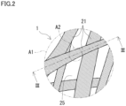
Fig. 2 is a schematic close-up view of a region A1 inFig. 1 . -
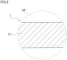
Fig. 3 is a schematic close-up cross-sectional view illustrating a region A2 in a III-III cross section inFig. 2 . -
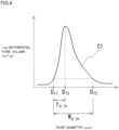
Fig. 4 is a graph for describing Log differential pore volume distribution of an electrode of a redox-flow battery system according to an embodiment. -
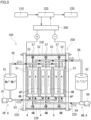
Fig. 5 is a schematic diagram illustrating the configuration of a redox-flow battery system according to an embodiment. -
Fig. 6 is a schematic diagram illustrating the configuration of a cell stack of a redox-flow battery system according to an embodiment. -
Fig. 7 is a schematic diagram illustrating the configuration of a measuring system used for measuring pressure loss of a redox-flow battery system in Test Examples. - Development of an electrode that is excellent in electrolyte flowability is demanded.
- An object of the present disclosure is to provide an electrode that is excellent in electrolyte flowability.
- An electrode according to the present disclosure is excellent in electrolyte flowability.
- First, aspects of the present disclosure will be described below.
- (1) An electrode according to an aspect of the present disclosure is
an electrode for use in a redox-flow battery system, the electrode comprising:- a carbon fiber; and
- a void, wherein
- a median diameter of the electrode based on pore volume determined by mercury porosimetry is at least 1.025 times a modal diameter of the electrode determined by mercury porosimetry.
- In an electrode in which the median diameter is at least 1.025 times the modal diameter, as compared to an electrode in which the median diameter is less than 1.025 times the modal diameter, the number of large voids is high. In the above-mentioned configuration in which the median diameter is at least 1.025 times the modal diameter, electrolyte flowability is excellent. As a result, in the above-mentioned configuration, diffusive resistance tends to be low.
- (2) In the electrode according to (1) above,
- the modal diameter may be 80 µm or less.
- An electrode in which the modal diameter is 80 µm or less has excellent battery reactivity.
- (3) In the electrode according to (1) above or (2) above,
- the median diameter may be 80 µm or less.
- An electrode in which the median diameter is 80 µm or less has excellent battery reactivity.
- (4) In the electrode according to any one of (1) above to (3) above,
on Log differential pore volume distribution of the electrode determined by mercury porosimetry, a symmetry factor S0.1h of a curve of a highest peak may be 1.5 or more. - As described below in detail referring to
Fig. 4 , the symmetry factor S0.1h is determined by (width W0.1h)/(2×(width f0.1h)). Width W0.1h is the difference between a first pore diameter D11 and a second pore diameter D12. Width f0.1h is the difference between first pore diameter D11 and a third pore diameter D13. First pore diameter D11 is the smaller of the pore diameters corresponding to 10% of the height of the highest peak on the curve. Second pore diameter D12 is the larger of the pore diameters corresponding to 10% of the height of the highest peak on the curve. Third pore diameter D13 is the pore diameter for the highest peak. - In an electrode in which the symmetry factor S0.1h is 1.5 or more, as compared to an electrode in which the symmetry factor S0.1h is less than 1.5, the number of large voids is high. In the above-mentioned configuration in which the symmetry factor S0.1h is 1.5 or more, electrolyte flowability is excellent.
- (5) In the electrode according to any one of (1) above to (4) above,
a porosity of the electrode determined by mercury porosimetry may be 60% or more. - An electrode in which the porosity is 60% or more has more voids, as compared to an electrode in which the porosity is less than 60%. In the above-mentioned configuration in which the porosity is 60% or more, electrolyte flowability is excellent.
- (6) In the electrode according to any one of (1) above to (5) above,
- the carbon fiber comprises a plurality of carbon fibers, and
- an average diameter of the plurality of carbon fibers may be from 2 µm to 30 µm.
- When the average diameter of the plurality of carbon fibers is 2 µm or more, the strength of the electrode is high. When the average diameter of the plurality of carbon fibers is 30 µm or less, the surface area of the carbon fibers per unit weight is large. This allows for sufficient battery reactions to occur in the electrode.
- (7) A battery cell according to an aspect of the present disclosure is a battery cell for use in a redox-flow battery system, and comprises the electrode according to any one of (1) above to (6) above.
- In the above-mentioned configuration which comprises an electrode that is excellent in electrolyte flowability, diffusive resistance tends to be low.
- (8) A cell stack according to an aspect of the present disclosure is a cell stack for use in a redox-flow battery system, and comprises a plurality of the battery cells according to (7) above.
- In the above-mentioned configuration which comprises a plurality of the above-mentioned battery cells, electrolyte flowability is excellent. As a result, in the above-mentioned configuration, diffusive resistance tends to be low.
- (9) A redox-flow battery system according to an aspect of the present disclosure comprises the battery cell according to (7) above or the cell stack according to (8) above.
- In the above-mentioned configuration which comprises the above-mentioned battery cell or the above-mentioned cell stack, electrolyte flowability is excellent. As a result, in the above-mentioned configuration, diffusive resistance tends to be low.
- (10) The redox-flow battery system according to (9) above may comprise a positive electrolyte and a negative electrolyte that are supplied to the battery cell,
- the positive electrolyte may include manganese ions, and
- the negative electrolyte may include titanium ions.
- The above-mentioned configuration has a high electromotive force.
- In the following, a redox-flow battery system according to an embodiment of the present disclosure is described in detail. Hereinafter, a redox-flow battery system may also be expressed as an RF battery system. In the drawings, members that have the same name are given the same reference numeral.
- Referring to
Fig. 1 to Fig. 6 , anRF battery system 100 according to an embodiment will be described. As illustrated inFig. 5 ,RF battery system 100 comprises abattery cell 4 and acirculation mechanism 6.Battery cell 4 has amembrane 4M, apositive electrode 4P, and anegative electrode 4N.Membrane 4M is interposed betweenpositive electrode 4P andnegative electrode 4N. At least one ofpositive electrode 4P andnegative electrode 4N is configured by anelectrode 1 illustrated inFig. 1 .Circulation mechanism 6 circulates an electrolyte tobattery cell 4. One of the characteristics ofRF battery system 100 according to the present embodiment is thatelectrode 1 has a particular structure. In the following, the outline and the fundamental configuration ofRF battery system 100, as well as the detailed configuration ofRF battery system 100 according to the present embodiment will be described in this order. -
RF battery system 100 illustrated inFig. 5 is charged with and stores the electric power generated in an electricpower generating member 310, discharges the electric power thus stored, and supplies it to aload 330. Typically,RF battery system 100 is connected to an AC/DC converter 300. AC/DC converter 300 is connected to atransformer facility 320.Transformer facility 320 is connected to electricpower generating member 310 andload 330. Electricpower generating member 310 is a photovoltaic power generator, a wind power generator, or other ordinary power plants, for example.Load 330 is an electric power consumer, for example. The solid arrow extending fromtransformer facility 320 toward AC/DC converter 300 represents charging. The broken arrow extending from AC/DC converter 300 towardtransformer facility 320 represents discharging.RF battery system 100 uses a positive electrolyte and a negative electrolyte. Each of the positive electrolyte and the negative electrolyte contains metal ions, as an active material, the valence of which changes along with oxidation and reduction. Charging and discharging ofRF battery system 100 proceed based on the difference between the redox potential of ions included in the positive electrolyte and the redox potential of ions included in the negative electrolyte.RF battery system 100 is used for the purpose of load leveling, instantaneous voltage drop compensation, emergency power source application, or output smoothing of natural energy, for example. The natural energy is the energy that is obtained by photovoltaic power generation or wind power generation, for example. -
Battery cell 4 inRF battery system 100 is divided bymembrane 4M into a positive electrode cell and a negative electrode cell.Membrane 4M is an ionexchange membrane that does not allow transmission of electrons but allows transmission of, for example, hydrogen ions. The positive electrode cell internally includespositive electrode 4P. The negative electrode cell internally includesnegative electrode 4N.Circulation mechanism 6 inRF battery system 100 comprises a positiveelectrode circulation mechanism 6P and a negativeelectrode circulation mechanism 6N. Positiveelectrode circulation mechanism 6P circulates the positive electrolyte to the positive electrode cell. Negativeelectrode circulation mechanism 6N circulates the negative electrolyte to the negative electrode cell. - As described above,
electrode 1 according to the present embodiment illustrated inFig. 1 configures at least one ofpositive electrode 4P andnegative electrode 4N illustrated inFig. 5 .Electrode 1 contributes to battery reactions.Electrode 1 has a sheet-like shape. In the present embodiment, the number ofelectrode 1 is one. - As illustrated in
Fig. 2 ,electrode 1 includescarbon fibers 21 as a main component. The expression "includescarbon fibers 21 as a main component" means that the ratio of the weight ofcarbon fibers 21 to the weight ofelectrode 1 is more than 40%. Further, the ratio of the weight ofcarbon fibers 21 to the weight ofelectrode 1 may be 50% or more, or 60% or more, or particularly 70% or more. In the present embodiment,electrode 1 includes a plurality ofcarbon fibers 21. The plurality ofcarbon fibers 21 form a three-dimensional network structure. Gaps in the network form voids 25. Typically, voids 25 are provided between the plurality ofcarbon fibers 21.Electrode 1 may include at least one of a binder, carbon particles, a catalyst, a hydrophilic material, and a hydrophobic material. The binder securescarbon fibers 21 to each other, and also secures carbon particles oncarbon fibers 21. The carbon particles increase the surface area ofelectrode 1. The catalyst facilitates battery reactions. Inelectrode 1 according to the present embodiment, as illustrated inFig. 3 ,carbon fibers 21 do not have carbon particles secured thereon.Electrode 1 satisfies a pore diameter dimensional relationship where the median diameter based on pore volume is at least 1.025 times the modal diameter. In other words, inelectrode 1, the difference between the median diameter and the modal diameter is at least 2.5% of the modal diameter. The difference between the median diameter and the modal diameter refers to ((median diameter)-(modal diameter)). - The median diameter based on pore volume is obtained from a cumulative pore volume curve of cumulative pore distribution based on mercury porosimetry. In the cumulative pore distribution, the X axis represents pore diameter and the Y axis represents pore volume. The median diameter based on pore volume is a pore diameter that corresponds to the midpoint between the smallest value and the largest value of the pore volume on the cumulative pore volume curve. The measurement range of the pore diameter on the X axis is defined by the upper limit and the lower limit measureable by mercury porosimetry. The upper limit corresponds to the smallest value of the pore volume on the Y axis. The lower limit corresponds to the largest value of the pore volume on the Y axis. The upper limit is usually about 500 µm. The lower limit is usually about 0.003 µm. The smallest value of the pore volume on the Y axis is usually 0 (zero). Herein, a median diameter based on pore volume may be simply referred to as a median diameter. The modal diameter is a pore diameter for the highest derivative value on the differential pore distribution based on mercury porosimetry.
- In
electrode 1 in which the median diameter is at least 1.025 times the modal diameter, as compared to an electrode in which the median diameter is less than 1.025 times the modal diameter, the number oflarge voids 25 is high. Alarge electrode 1 in which the median diameter is at least 1.025 times the modal diameter is excellent in electrolyte flowability. - Further, the median diameter may be at least 1.03 times the modal diameter, particularly at least 1.05 times the modal diameter. The median diameter is at most 1.5 times the modal diameter, further at most 1.3 times the modal diameter, particularly at most 1.2 times the modal diameter, for example. In other words, the median diameter is from 1.025 times to 1.5 times the modal diameter, further from 1.03 times to 1.3 times the modal diameter, particularly from 1.05 times to 1.2 times the modal diameter. Further, the difference between the median diameter and the modal diameter may be at least 3% of the modal diameter, particularly at least 5% of the modal diameter. The difference between the median diameter and the modal diameter is at most 50% of the modal diameter, further at most 30% of the modal diameter, particularly at most 20% of the modal diameter, for example. In other words, the difference between the median diameter and the modal diameter is from 2.5% to 50% of the modal diameter, further from 3% to 30% of the modal diameter, particularly from 5% to 20% of the modal diameter.
- The median diameter is 80 µm or less, for example.
Electrode 1 in which the median diameter is 80 µm or less has excellent battery reactivity. Further, the median diameter is 75 µm or less, or 60 µm or less, or 55 µm or less, or particularly 50 µm or less. The lower limit to the median diameter is 3 µm, for example. In other words, the median diameter is from 3 µm to 80 µm, further from 10 µm to 75 µm, particularly from 20 µm to 60 µm. - The modal diameter is 80 µm or less, for example.
Electrode 1 in which the modal diameter is 80 µm or less has excellent battery reactivity. Further, the modal diameter is 75 µm or less, or 60 µm or less, or 55 µm or less, or particularly 50 µm or less. The lower limit to the modal diameter is 2 µm, for example. In other words, the modal diameter is from 2 µm to 80 µm, further from 10 µm to 75 µm, particularly from 20 µm to 60 µm. - The symmetry factor S0.1h of the curve is 1.5 or more, for example. Referring to
Fig. 4 , the symmetry factor S0.1h of a curve C1 will be described. Curve C1 inFig. 4 is a graph of Log differential pore volume distribution ofelectrode 1 determined by mercury porosimetry. The horizontal axis inFig. 4 represents the pore diameter (µm) ofelectrode 1. The horizontal axis means that the pore diameter becomes larger as it goes toward the right on the paper. The vertical axis inFig. 4 represents the Log differential pore volume (cm3/g) ofelectrode 1. The vertical axis means that the Log differential pore volume becomes larger as it goes upward on the paper.Fig. 4 is provided for the purpose of clearly explaining the symmetry factor S0.1h of curve C1, and it does not necessarily give theactual curve C 1. As illustrated inFig. 4 , curve C1 ofelectrode 1 has a single peak. - The symmetry factor S0.1h is determined by "(width W0.1h)/(2×(width f0.1h))". Width W0.1h is the difference between a first pore diameter D11 and a second pore diameter D12. Width f0.1h is the difference between first pore diameter D11 and a third pore diameter D13. First pore diameter D11 is the smaller of the pore diameters corresponding to 10% of the height of the highest peak on curve C1. Second pore diameter D12 is the larger of the pore diameters corresponding to 10% of the height of the highest peak on curve C1. Third pore diameter D13 is the pore diameter for the highest peak on curve C1.
- In
electrode 1 in which the symmetry factor S0.1h is 1.5 or more, as compared to an electrode in which the symmetry factor S0.1h is less than 1.5, the number oflarge voids 25 is high.Electrode 1 in which the symmetry factor S0.1h is 1.5 or more is excellent in electrolyte flowability. Further, the symmetry factor S0.1h is 1.6 or more, particularly 1.7 or more. The symmetry factor S0.1h is 15 or less, or further 10 or less, for example. In other words, the symmetry factor S0.1h is from 1.5 to 15, further from 1.6 to 10, particularly from 1.7 to 10. - The average diameter of the plurality of
carbon fibers 21 is from 2 µm to 30 µm, for example. When the average diameter of the plurality ofcarbon fibers 21 is 2 µm or more, the strength ofelectrode 1 is high. When the average diameter of the plurality ofcarbon fibers 21 is 30 µm or less, the surface area ofcarbon fibers 21 per unit weight is large. This allows for sufficient battery reactions to occur inelectrode 1. Further, the average diameter of the plurality ofcarbon fibers 21 is from 5 µm to 25 µm, particularly from 7 µm to 20 µm. - The average diameter of the plurality of
carbon fibers 21 is the average of the diameters of circles that have the same area as the cross-sectional area ofrespective carbon fibers 21, and is determined in the below-described manner.Electrode 1 is cut in the thickness direction, to expose cross sections of the plurality ofcarbon fibers 21. In the cross section ofelectrode 1, five or more fields of view are selected under a microscope. As the microscope, a scanning electron microscope (SEM) is used. The magnification is from 500 times to 3000 times. For three ormore carbon fibers 21 per one examination field of view, the diameter of a circle that has the same area as the cross-sectional area thereof is determined. The diameters of the circles determined in all the examination fields of view are averaged. - The mass per unit area of
electrode 1 is from 20 g/m2 to 400 g/m2, for example.Electrode 1 in which the mass per unit area is 20 g/m2 or more tends to have many contact points betweencarbon fibers 21. Therefore,electrode 1 tends to have an enhanced conductivity. Inelectrode 1 in which the mass per unit area is 400 g/m2 or less, voids 25 tend to be ensured. Therefore,electrode 1 is excellent in electrolyte flowability. Further, the mass per unit area ofelectrode 1 is from 25 g/m2 to 300 g/m2, particularly from 30 g/m2 to 200 g/m2. The mass per unit area is determined by measuring the weight per unit area. - The porosity of
electrode 1 is 60% or more, for example. The porosity is determined by mercury porosimetry. The porosity refers to the proportion of the volume of the pores to the volume ofelectrode 1 including the pores.Electrode 1 in which the porosity is 60% or more hasmore voids 25, as compared to an electrode in which the porosity is less than 60%. Thiselectrode 1 is excellent in electrolyte flowability. The upper limit to the porosity ofelectrode 1 is 99%, for example.Electrode 1 in which the porosity is 99% or less has excellent battery reactivity. The porosity ofelectrode 1 is from 60% to 99%, or from 60% to 95%, further from 65% to 93%, particularly from 75% to 90%. -
Electrode 1 is one selected from the group consisting of nonwoven fabric, woven fabric, and paper. The nonwoven fabric is formed ofindependent carbon fibers 21 entangled together. The woven fabric is formed of the warp and the weft ofcarbon fibers 21 woven alternately. The paper has the plurality ofcarbon fibers 21 and a binder for securing thecarbon fibers 21. -
Electrode 1 according to the present embodiment is a nonwoven fabric. For example,electrode 1 according to the present embodiment is formed ofcarbon fibers 21 entangled together by needle-punching, water punching, and/or stitch bonding. For example,electrode 1 according to the present embodiment is obtained by adjusting, as appropriate, the average diameter ofcarbon fibers 21, the average length ofcarbon fibers 21, the mass per unit area, and the entangling conditions. -
Battery cell 4 is usually formed inside a structure called acell stack 200, as illustrated inFig. 5 and in the lower drawing ofFig. 6 .Cell stack 200 comprises sub stacks 201, twoend plates 220, and afastening mechanism 230.Cell stack 200 illustrated in the lower drawing ofFig. 6 has a configuration where it comprises a plurality of sub stacks 201. As illustrated in the lower drawing ofFig. 6 , eachsub stack 201 comprises a stack and two supply/drainage plates 210. As illustrated inFig. 5 and in the upper drawing ofFig. 6 , the stack is formed by stacking multiple sets of acell frame 5,positive electrode 4P,membrane 4M, andnegative electrode 4N in this order. As illustrated in the lower drawing ofFig. 6 , supply/drainage plates 210 are placed at both ends of the stack. To supply/drainage plates 210, asupply tube 63 and adischarge tube 65 of positiveelectrode circulation mechanism 6P, as well as asupply tube 64 and adischarge tube 66 of negativeelectrode circulation mechanism 6N are connected, which are described below. Twoend plates 220 sandwich the plurality ofsub stacks 201 from outside of the two outermost sub stacks 201.Fastening mechanism 230 fastens bothend plates 220. - As illustrated in
Fig. 6 ,cell frame 5 comprises abipolar plate 51 and aframe member 52.Frame member 52 surrounds the outer circumference ofbipolar plate 51. Betweenbipolar plates 51 of cell frames 5 that are adjacent to each other, asingle battery cell 4 is formed.Bipolar plate 51 has a surface facingpositive electrode 4P and a surface facingnegative electrode 4N. Atframe member 52,liquid supply manifolds liquid supply slits liquid discharge manifolds liquid discharge slits frame members 52, a ring-shaped sealingmember 57 is placed in a ring-shaped sealing groove. - As illustrated in
Fig. 5 , positiveelectrode circulation mechanism 6P comprises apositive electrolyte tank 61,supply tube 63,discharge tube 65, and apump 67.Positive electrolyte tank 61 stores the positive electrolyte. Throughsupply tube 63 anddischarge tube 65, the positive electrolyte flows.Supply tube 63 connectspositive electrolyte tank 61 with the positive electrode cell.Discharge tube 65 connects the positive electrode cell withpositive electrolyte tank 61.Pump 67 pressure feeds the positive electrolyte frompositive electrolyte tank 61.Pump 67 is provided at some midpoint on thesupply tube 63. - Negative
electrode circulation mechanism 6N comprises anegative electrolyte tank 62,supply tube 64,discharge tube 66, and apump 68.Negative electrolyte tank 62 stores the negative electrolyte. Throughsupply tube 64 anddischarge tube 66, the negative electrolyte flows.Supply tube 64 connectsnegative electrolyte tank 62 with the negative electrode cell.Discharge tube 66 connects the negative electrode cell withnegative electrolyte tank 62.Pump 68 pressure feeds the negative electrolyte fromnegative electrolyte tank 62.Pump 68 is provided at some midpoint on thesupply tube 64. - During charging or discharging operation, the positive electrolyte and the negative electrolyte flow in the manner described below. By
pump 67, the positive electrolyte flows frompositive electrolyte tank 61 throughsupply tube 63, and is supplied to the positive electrode cell. The positive electrolyte flows fromliquid supply manifold 53 throughliquid supply slit 53s illustrated in the upper drawing ofFig. 6 , and is supplied topositive electrode 4P. The positive electrolyte thus supplied topositive electrode 4P flows from the lower edge ofpositive electrode 4P toward the upper edge, as shown by the arrows in the upper drawing ofFig. 6 . The positive electrolyte thus flown throughpositive electrode 4P flows through liquid discharge slit 55s, and is discharged intoliquid discharge manifold 55. The positive electrolyte flows from the positive electrode cell throughdischarge tube 65, and is discharged intopositive electrolyte tank 61. Bypump 68, the negative electrolyte flows fromnegative electrolyte tank 62 throughsupply tube 64, and is supplied to the negative electrode cell. The negative electrolyte flows fromliquid supply manifold 54 throughliquid supply slit 54s, and is supplied tonegative electrode 4N. The negative electrolyte thus supplied tonegative electrode 4N flows from the lower edge ofnegative electrode 4N toward the upper edge, as shown by the arrows in the upper drawing ofFig. 6 . The negative electrolyte thus flown throughnegative electrode 4N flows through liquid discharge slit 56s, and is discharged intoliquid discharge manifold 56. The negative electrolyte flows from the negative electrode cell throughdischarge tube 66, and is discharged intonegative electrolyte tank 62. By the supplying and discharging, the positive electrolyte and the negative electrolyte are circulated to the positive electrode cell and the negative electrode cell. During standby in which neither charging nor discharging takes place, pump 67 and pump 68 are halted. That is, the positive electrolyte and the negative electrolyte are not circulated. - A positive electrode active material included in the positive electrolyte is one or more types selected from the group consisting of manganese ions, vanadium ions, iron ions, polyacids, quinone derivatives, and amines. A negative electrode active material included in the negative electrolyte is one or more types selected from the group consisting of titanium ions, vanadium ions, chromium ions, polyacids, quinone derivatives, and amines. When the positive electrolyte includes manganese ions and the negative electrolyte includes titanium ions,
RF battery system 100 tends to have a high electromotive force. InFig. 5 , the ions included in the positive electrolyte are manganese (Mn) ions and the ions included in the negative electrolyte are titanium (Ti) ions. Each of a solvent of the positive electrolyte and a solvent of the negative electrolyte is, for example, an aqueous solution that includes one or more acids, or salt(s) of one or more acids, selected from the group consisting of sulfuric acid, phosphoric acid, nitric acid, and hydrochloric acid. -
RF battery system 100 according to the present embodiment compriseselectrode 1 that is excellent in electrolyte flowability, and therefore tends to have a low diffusive resistance. - A plurality of electrodes were prepared, and battery reactivity and electrolyte flowability were evaluated.
- The electrode of the battery cell of Sample No. 1 to Sample No. 6 each was a single electrode that included a plurality of carbon fibers and voids. The average diameter of the carbon fibers of each sample is within the range of 2 µm to 30 µm. The average diameter of the carbon fibers was determined by the method described in the embodiment section. The mass per unit area of the electrode of Sample No. 1 is 110 g/m2. The mass per unit area of the electrode of Sample No. 2 is 120 g/m2. The mass per unit area of the electrode of Sample No. 3 is 80 g/m2. The mass per unit area of the electrode of Sample No. 4 is 90 g/m2. The mass per unit area of the electrode of Sample No. 5 is 90 g/m2. The mass per unit area of the electrode of Sample No. 6 is 100 g/m2. The mass per unit area was determined by the method described in the embodiment section.
- The median diameter based on pore volume, the modal diameter, the symmetry factor, and the porosity of the electrode of each sample are shown in Table 1. These values were measured by mercury porosimetry. For the measurement, a pore distribution measurement apparatus AutoPore IV 9520 manufactured by Shimadzu Corporation-Micromeritics Instrument Corporation was used. In Table 1, the value of the modal diameter of the electrode of each sample multiplied by 1.025 is also given. The value of the modal diameter multiplied by 1.025 has been rounded to three decimal place.
- Each electrode was cut into a strip having a size of about 12.5 mm×25 mm, which was used as a measurement sample. The weight of the measurement sample was approximately from 0.03 g to 0.24 g. The measurement sample was placed in a 5-cc cell that was specifically designed for powder. The volume of the stem of the powder cell is 0.4 cc. The measurement was carried out under the conditions of an initial pressure of about 3.7 kPa. "About 3.7 kPa" corresponds to about 0.5 psia (pound-force per square inch absolute), and corresponds to a pore diameter of about 340 µm. The mercury parameters were set at the default of the apparatus, namely a mercury contact angle of 130 degrees and a mercury surface tension of 485 dynes/cm (485 mN/m).
- The electrode of the battery cell of Sample No. 101 was a single electrode. The electrode of Sample No. 101 includes carbon fibers. The median diameter based on pore volume, the modal diameter, the symmetry factor, and the porosity of the electrode of Sample No. 101 are shown in Table 1. In Table 1, the value of the modal diameter of the electrode of Sample No. 101 multiplied by 1.025 is also given. The value of the modal diameter multiplied by 1.025 has been rounded to three decimal place.
[Table 1] Sample No. Median diameter Modal diameter Modal diameter × 1.025 Symmetry factor Porosity µm µm µm % 1 40.1 34.5 35.36 7.96 94 2 49.8 45.6 46.74 2.52 93 3 44.3 42.3 43.36 3.41 88 4 46.6 44.2 45.31 3.05 88 5 70.3 66.5 68.16 3.94 86 6 68.8 64.9 66.52 2.23 81 101 24.1 23.6 24.19 1.42 84 - The battery cell of each sample was used to produce a single-cell battery, and various resistivities described below were measured. The single-cell battery is a battery that comprises a single positive electrode, a single membrane, and a single negative electrode. The single-cell battery was formed by stacking a first cell frame, a positive electrode, a membrane, a negative electrode, and a second cell frame in this order. The membrane is sandwiched between the positive electrode and the negative electrode. The first cell frame is placed so that a bipolar plate of the first cell frame comes into contact with the positive electrode. The second cell frame is placed so that a bipolar plate of the second cell frame comes into contact with the negative electrode. As the positive electrode, a carbon paper sheet was used. As the negative electrode, the electrode of each sample was used. As the positive electrolyte, a manganese sulfate solution that included manganese ions as an active material was used. As the negative electrolyte, a titanium sulfate solution that included titanium ions as an active material was used.
- The battery cell of each sample was subjected to constant-current charging and discharging at a current density of 100 mA/cm2. In this test, three cycles of charging and discharging were carried out. In this test, charging was switched to discharging when a previously defined switching voltage was reached, and discharging was switched to charging when a previously defined switching voltage was reached. The switching voltage for switching from charging to discharging was 1.62 V. The switching voltage for switching from discharging to charging was 1.0 V. In this manner, charging and discharging of the RF battery of each sample were accomplished.
- After the constant-current charging and discharging, another charging was carried out in the manner described below, and the conductive resistivity (Ω·cm2), the charge-transfer resistivity (Ω·cm2), and the diffusive resistivity (Ω·cm2) of each sample were determined by the methods described below. Results are given in Table 2, together with the cell resistivity (Ω·cm2). Cell resistivity is the sum of conductive resistivity, charge-transfer resistivity, and diffusive resistivity. The charging here was carried out to reach a midpoint SOC. The midpoint SOC is an average value of the sum of the highest SOC value and the lowest SOC value during the constant-current charging and discharging.
- The conductive resistivity was an impedance at the time when the measurement frequency in the alternating-current impedance method was 1 kHz.
- The charge-transfer resistivity was measured by an alternating-current impedance method. For the measurement of the charge-transfer resistivity, a commercially-available measurement apparatus was used, under a bias at a value around the open circuit voltage, at a voltage amplitude of 10 mV, at a measurement frequency within the range of 10 kHz to 10 mHz.
- In the same manner as for the charge-transfer resistivity, the diffusive resistivity was measured by an alternating-current impedance method.
- With the use of a
measuring system 600 illustrated inFig. 7 , pressure loss ΔP of each sample was measured. Measuringsystem 600 comprises ameasurement cell 610, afluid tank 620, apipe 630, apump 640, aflowmeter 650, and adifferential pressure gauge 660. -
Measurement cell 610 is a single-cell battery that has the same structure as the single-cell battery used in the above-described measurement of various resistivities.Fluid tank 620 stores a fluid 622 that is to be supplied to the electrode inside themeasurement cell 610.Fluid 622 is water, for example.Pipe 630 connectsfluid tank 620 withmeasurement cell 610.Pump 640 is provided topipe 630, and pressure feeds fluid 622 fromfluid tank 620 tomeasurement cell 610.Fluid 622 discharged frommeasurement cell 610 flows throughpipe 630 back tofluid tank 620. In this manner, bypump 640 andpipe 630,fluid 622 inside thefluid tank 620 is circulated and supplied tomeasurement cell 610. The dash-dot arrows inFig. 7 represent the direction of flow offluid 622.Flowmeter 650 is placed onpipe 630, at a position downstream ofpump 640 and upstream ofmeasurement cell 610.Flowmeter 650 measures the flow rate offluid 622 discharged frompump 640. Onpipe 630, at a position downstream offlowmeter 650, abranch pipe 632 for bypassingmeasurement cell 610 is provided.Differential pressure gauge 660 is provided onbranch pipe 632. Moreover,differential pressure gauge 660 is provided in parallel withmeasurement cell 610. -
Differential pressure gauge 660 measures the difference (P0-P1) between a pressure P0 offluid 622 supplied tomeasurement cell 610 and a pressure P1 offluid 622 discharged frommeasurement cell 610. Pressure loss ΔP is the difference between these pressures, (P0-P1). The lower the pressure loss ΔP is, the more excellent in electrolyte flowability themeasurement cell 610 is considered to be. Results of the pressure loss of each sample are shown in Table 2. The result of the pressure loss in Table 2 is expressed as a value relative to the pressure loss ΔP of Sample No. 1, which is regarded as 1.0.[Table 2] Sample No. Conductive resistivity Charge-transfer resistivity Diffusive resistivity Cell resistivity Pressure loss Ω·cm2 Ω·cm2 Ω·cm2 Ω· cm 21 0.25 0.19 0.16 0.60 1.0 2 0.25 0.22 0.18 0.65 1.0 3 0.23 0.15 0.12 0.50 1.1 4 0.24 0.17 0.14 0.55 1.1 5 0.25 0.19 0.13 0.56 1.1 6 0.20 0.19 0.09 0.48 1.1 101 0.22 0.23 0.35 0.80 1.3 - Referring to Table 2, Sample No. 1 to Sample No. 6 had low diffusive resistivity as compared to Sample No. 101. The difference between the diffusive resistivity of each of Sample No. 1 to Sample No. 6 and the diffusive resistivity of Sample No. 101 was greater than the difference between the conductive resistivity of each of Sample No. 1 to Sample No. 6 and the conductive resistivity of Sample No. 101. The difference between the diffusive resistivity of each of Sample No. 1 to Sample No. 6 and the diffusive resistivity of Sample No. 101 was greater than the difference between the charge-transfer resistivity of each of Sample No. 1 to Sample No. 6 and the charge-transfer resistivity of Sample No. 101. This indicates that the diffusive resistivity lowering effect of Sample No. 1 to Sample No. 6 was greater than that of Sample No. 101. The pressure loss of each of Sample No. 1 to Sample No. 6 was smaller than that of Sample No. 101. Due to the great diffusive resistivity lowering effect and the small pressure loss as compared to Sample No. 101, Sample No. 1 to Sample No. 6 were found to be particularly excellent in electrolyte flowability.
- Sample No. 1 to Sample No. 6 had low cell resistivity as compared to Sample No. 101. This indicates that Sample No. 1 to Sample No. 6 are also excellent in battery reactivity as compared to Sample No. 101.
- It is intended that the scope of the present invention is defined by claims, not by these examples, and encompasses all modifications and variations equivalent in meaning and scope to the claims.
-
- 100 RF battery system
- 1 electrode
- 21 carbon fiber, 25 void
- 4 battery cell, 4M membrane, 4P positive electrode, 4N negative electrode
- 5 cell frame, 51 bipolar plate, 52 frame member
- 53, 54 liquid supply manifold, 53s, 54s liquid supply slit
- 55, 56 liquid discharge manifold, 55s, 56s liquid discharge slit
- 57 sealing member
- 6 circulation mechanism, 6P positive electrode circulation mechanism, 6N negative electrode circulation mechanism
- 61 positive electrolyte tank, 62 negative electrolyte tank
- 63, 64 supply tube, 65, 66 discharge tube, 67, 68 pump
- 200 cell stack, 201 sub stack
- 210 supply/drainage plate, 220 end plate, 230 fastening mechanism
- 300 AC/DC converter, 310 electric power generating member
- 320 transformer facility, 330 load
- 600 measuring system, 610 measurement cell, 620 fluid tank
- 622 fluid, 630 pipe, 632 branch pipe, 640 pump
- 650 flowmeter, 660 differential pressure gauge
- C1 curve
Claims (10)
- An electrode for use in a redox-flow battery system, the electrode comprising:a carbon fiber; anda void, whereina median diameter of the electrode based on pore volume determined by mercury porosimetry is at least 1.025 times a modal diameter of the electrode determined by mercury porosimetry.
- The electrode according to claim 1, wherein the modal diameter is 80 µm or less.
- The electrode according to claim 1 or 2, wherein the median diameter is 80 µm or less.
- The electrode according to any one of claims 1 to 3, wherein on Log differential pore volume distribution of the electrode determined by mercury porosimetry, a symmetry factor S0.1h of a curve of a highest peak is 1.5 or more.
- The electrode according to any one of claims 1 to 4, wherein a porosity of the electrode determined by mercury porosimetry is 60% or more.
- The electrode according to any one of claims 1 to 5, whereinthe carbon fiber comprises a plurality of carbon fibers, andan average diameter of the plurality of carbon fibers is from 2 µm to 30 µm.
- A battery cell for use in a redox-flow battery system, the battery cell comprising the electrode according to any one of claims 1 to 6.
- A cell stack for use in a redox-flow battery system, the cell stack comprising a plurality of the battery cells according to claim 7.
- A redox-flow battery system comprising the battery cell according to claim 7 or the cell stack according to claim 8.
- The redox-flow battery system according to claim 9, comprising:a positive electrolyte and a negative electrolyte that are supplied to the battery cell, whereinthe positive electrolyte includes manganese ions, andthe negative electrolyte includes titanium ions.
Applications Claiming Priority (2)
| Application Number | Priority Date | Filing Date | Title |
|---|---|---|---|
| JP2022000990 | 2022-01-06 | ||
| PCT/JP2022/043803 WO2023132152A1 (en) | 2022-01-06 | 2022-11-28 | Electrode, battery cell, cell stack, and redox-flow battery system |
Publications (2)
| Publication Number | Publication Date |
|---|---|
| EP4462521A1 true EP4462521A1 (en) | 2024-11-13 |
| EP4462521A4 EP4462521A4 (en) | 2025-11-19 |
Family
ID=87073430
Family Applications (1)
| Application Number | Title | Priority Date | Filing Date |
|---|---|---|---|
| EP22918739.8A Pending EP4462521A4 (en) | 2022-01-06 | 2022-11-28 | ELECTRODE, BATTERY CELL, CELL STACK AND REDOX FLOW BATTERY SYSTEM |
Country Status (6)
| Country | Link |
|---|---|
| US (1) | US20250087709A1 (en) |
| EP (1) | EP4462521A4 (en) |
| JP (1) | JPWO2023132152A1 (en) |
| CN (1) | CN118511336A (en) |
| AU (1) | AU2022431532A1 (en) |
| WO (1) | WO2023132152A1 (en) |
Family Cites Families (7)
| Publication number | Priority date | Publication date | Assignee | Title |
|---|---|---|---|---|
| JPS5937662A (en) * | 1982-08-24 | 1984-03-01 | Kureha Chem Ind Co Ltd | Electrode substrate for monopolar type fuel cell with two-layer structure |
| CN103999264B (en) | 2011-12-20 | 2016-08-24 | 联合工艺公司 | There is the flow battery of carbon paper |
| US9236620B2 (en) * | 2012-11-05 | 2016-01-12 | Battelle Memorial Institute | Composite separators and redox flow batteries based on porous separators |
| KR102384790B1 (en) | 2014-08-25 | 2022-04-08 | 한국전자통신연구원 | Apparatus for generating broadcasting signal frame using layered division multiplexing and method using the same |
| JP2020035732A (en) * | 2018-08-24 | 2020-03-05 | 旭化成株式会社 | Electrodes for redox flow batteries |
| JP7330028B2 (en) * | 2019-09-13 | 2023-08-21 | 株式会社東芝 | Electrodes, secondary batteries, battery packs, and vehicles |
| JPWO2021225106A1 (en) * | 2020-05-08 | 2021-11-11 |
-
2022
- 2022-11-28 CN CN202280087607.0A patent/CN118511336A/en active Pending
- 2022-11-28 EP EP22918739.8A patent/EP4462521A4/en active Pending
- 2022-11-28 AU AU2022431532A patent/AU2022431532A1/en active Pending
- 2022-11-28 US US18/726,497 patent/US20250087709A1/en active Pending
- 2022-11-28 WO PCT/JP2022/043803 patent/WO2023132152A1/en not_active Ceased
- 2022-11-28 JP JP2023572375A patent/JPWO2023132152A1/ja active Pending
Also Published As
| Publication number | Publication date |
|---|---|
| JPWO2023132152A1 (en) | 2023-07-13 |
| EP4462521A4 (en) | 2025-11-19 |
| AU2022431532A1 (en) | 2024-07-11 |
| WO2023132152A1 (en) | 2023-07-13 |
| CN118511336A (en) | 2024-08-16 |
| WO2023132152A8 (en) | 2024-03-28 |
| US20250087709A1 (en) | 2025-03-13 |
Similar Documents
| Publication | Publication Date | Title |
|---|---|---|
| EP3098888B1 (en) | Redox flow battery | |
| EP2827412A1 (en) | Microtubes made of carbon nanotubes | |
| JP2015122231A (en) | Redox flow cell | |
| JP2015122230A (en) | Redox flow cell | |
| US20180366736A1 (en) | Electrode material, electrode of redox flow battery, and redox flow battery | |
| US11784339B2 (en) | Battery cell, cell stack, and redox flow battery | |
| EP3327839A1 (en) | Redox flow battery electrode, redox flow battery, and method for evaluating electrode properties | |
| JP6970388B2 (en) | Redox flow battery electrodes, redox flow battery cells and redox flow batteries | |
| EP3522279A1 (en) | Redox flow battery | |
| EP3367487B1 (en) | Redox flow battery electrode, and redox flow battery | |
| US20200350597A1 (en) | Electrode for redox flow battery, and redox flow battery | |
| JP6961432B2 (en) | Electrodes, membrane electrode assemblies, electrochemical cells, stacks, fuel cells, vehicles and flying objects | |
| US20250087709A1 (en) | Electrode, battery cell, cell stack, and redox-flow battery system | |
| JP2023100374A (en) | Electrodes, battery cells, cell stacks, and redox flow battery systems | |
| EP3496198A1 (en) | Redox flow battery | |
| JP7286063B2 (en) | Redox flow battery cell, cell stack, and redox flow battery system | |
| JP2024075814A (en) | Electrode, battery cell, and redox flow battery | |
| JP2023100373A (en) | Electrodes, battery cells, cell stacks, and redox flow battery systems | |
| EP4462522A1 (en) | Electrode, battery cell, cell stack, and redox-flow battery system | |
| JP7232431B2 (en) | Electrodes, battery cells, cell stacks, and redox flow battery systems | |
| JP7486060B2 (en) | Cell stack and redox flow battery | |
| JP7286062B2 (en) | Redox flow battery cell, cell stack, and redox flow battery system | |
| WO2024075439A1 (en) | Redox flow battery electrode, redox flow battery cell, and redox flow battery system | |
| EP4177022A1 (en) | Electrode, battery cell, cell stack, battery system, and method for manufacturing electrode | |
| JP2021061199A (en) | Fuel cell stack |
Legal Events
| Date | Code | Title | Description |
|---|---|---|---|
| STAA | Information on the status of an ep patent application or granted ep patent |
Free format text: STATUS: THE INTERNATIONAL PUBLICATION HAS BEEN MADE |
|
| PUAI | Public reference made under article 153(3) epc to a published international application that has entered the european phase |
Free format text: ORIGINAL CODE: 0009012 |
|
| STAA | Information on the status of an ep patent application or granted ep patent |
Free format text: STATUS: REQUEST FOR EXAMINATION WAS MADE |
|
| 17P | Request for examination filed |
Effective date: 20240701 |
|
| AK | Designated contracting states |
Kind code of ref document: A1 Designated state(s): AL AT BE BG CH CY CZ DE DK EE ES FI FR GB GR HR HU IE IS IT LI LT LU LV MC ME MK MT NL NO PL PT RO RS SE SI SK SM TR |
|
| DAV | Request for validation of the european patent (deleted) | ||
| DAX | Request for extension of the european patent (deleted) | ||
| A4 | Supplementary search report drawn up and despatched |
Effective date: 20251016 |
|
| RIC1 | Information provided on ipc code assigned before grant |
Ipc: H01M 4/96 20060101AFI20251010BHEP Ipc: H01M 8/18 20060101ALI20251010BHEP Ipc: H01M 4/86 20060101ALI20251010BHEP |