EP4462451A1 - Power cable with lead-free metal water barrier - Google Patents
Power cable with lead-free metal water barrier Download PDFInfo
- Publication number
- EP4462451A1 EP4462451A1 EP23315176.0A EP23315176A EP4462451A1 EP 4462451 A1 EP4462451 A1 EP 4462451A1 EP 23315176 A EP23315176 A EP 23315176A EP 4462451 A1 EP4462451 A1 EP 4462451A1
- Authority
- EP
- European Patent Office
- Prior art keywords
- metal layer
- alloy
- conductor
- sheath
- power cable
- Prior art date
- Legal status (The legal status is an assumption and is not a legal conclusion. Google has not performed a legal analysis and makes no representation as to the accuracy of the status listed.)
- Pending
Links
Images


Classifications
-
- H—ELECTRICITY
- H01—ELECTRIC ELEMENTS
- H01B—CABLES; CONDUCTORS; INSULATORS; SELECTION OF MATERIALS FOR THEIR CONDUCTIVE, INSULATING OR DIELECTRIC PROPERTIES
- H01B7/00—Insulated conductors or cables characterised by their form
- H01B7/17—Protection against damage caused by external factors, e.g. sheaths or armouring
- H01B7/18—Protection against damage caused by wear, mechanical force or pressure; Sheaths; Armouring
- H01B7/20—Metal tubes, e.g. lead sheaths
- H01B7/202—Longitudinal lapped metal tubes
-
- H—ELECTRICITY
- H01—ELECTRIC ELEMENTS
- H01B—CABLES; CONDUCTORS; INSULATORS; SELECTION OF MATERIALS FOR THEIR CONDUCTIVE, INSULATING OR DIELECTRIC PROPERTIES
- H01B13/00—Apparatus or processes specially adapted for manufacturing conductors or cables
- H01B13/22—Sheathing; Armouring; Screening; Applying other protective layers
- H01B13/26—Sheathing; Armouring; Screening; Applying other protective layers by winding, braiding or longitudinal lapping
- H01B13/2613—Sheathing; Armouring; Screening; Applying other protective layers by winding, braiding or longitudinal lapping by longitudinal lapping
- H01B13/2693—After-treatment
-
- H—ELECTRICITY
- H01—ELECTRIC ELEMENTS
- H01B—CABLES; CONDUCTORS; INSULATORS; SELECTION OF MATERIALS FOR THEIR CONDUCTIVE, INSULATING OR DIELECTRIC PROPERTIES
- H01B7/00—Insulated conductors or cables characterised by their form
- H01B7/17—Protection against damage caused by external factors, e.g. sheaths or armouring
- H01B7/28—Protection against damage caused by moisture, corrosion, chemical attack or weather
- H01B7/282—Preventing penetration of fluid, e.g. water or humidity, into conductor or cable
- H01B7/2825—Preventing penetration of fluid, e.g. water or humidity, into conductor or cable using a water impermeable sheath
Definitions
- the present invention relates to a power cable having a non-leaded metallic water barrier.
- High voltage cables contain one or more electrically insulated current carrying conductors at its core section. However, intrusion of humidity or water into the core section may cause electrical breakdown of the insulation system making it vital to keep the current carrying core of high voltage power cables dry. High voltage power cables are therefore typically equipped with a circumferentially arranged water-tight layer sealing off the current carrying parts of the power cable towards ambient moisture/water.
- the water-barrier layer typically comprises a layer of a metal.
- Lead/lead-alloys are commonly applied.
- lead is a high-density materiel adding significant weight to the cable. The heavy weight induces extra costs in the entire value chain from production, under transport, storage, deployment, and when the cable is discarded after reaching its lifetime.
- Lead is also a neurotoxic material meeting increasing environmental regulation restrictions.
- lead has a relatively low fatigue resistance making leaden water barriers less suited for dynamical power cables.
- a known alternative to water barriers of lead is the use of high resistance (non-lead) metallic screens laid around the core and/or the insulated conductors of the power cable and joining opposite ends of the wrapped screen by e.g. welding.
- these alternative water barriers still have an unacceptable risk of failure, especially when producing long cables of several kilometres of length, because it is difficult to identify eventual production failures due to the welding process- in the welding seam such as e.g. pinholes in the metal, welding defects, etc.
- the main objective of the invention is to provide a high-voltage power cable having a lead-free low weight water-barrier around the cable core and/or the conductor(s) of the power cable.
- the inventors have now shown that, when applying a high resistance (non-leaded) metallic screen covering the core and/or the insulated conductors of the power cable by being wrapped around and joined by welding, the problem with potential production defects along the welding seam, such as e.g. pinholes in the metal, welding defects etc., may be repaired and/or sealed by utilizing additive manufacturing techniques to deposit a metal layer at least covering identified welding defects in said welding seam, or alternatively covering the entire welded seam of the metallic screen.
- the invention relates to a power cable comprising:
- the metal sheath preferably encapsulates:
- longitudinal refers to the main direction of the power cable. Namely, a longitudinal direction is parallel with or co-axial with the longitudinal centre axis of the power cable.
- metal sheath refers to the primary water-impenetrable layer of the water-barrier system of the invention.
- the metal sheath is typically formed by folding and welding together opposite ends of a metal foil such that the resulting metal sheath is laid around to encompass and encapsulate the core and/or the insulated conductors of the power cable.
- the invention is not tied to use of any specific metal foil to make the metal sheath, except that it should not be made of Pb or a Pb-alloy.
- the metal foil may be made of any non-lead metal/metal alloy having any thickness known to the skilled person to be suited for use as a metallic screen/water-barrier in power cables.
- the metal foil is either an Al/Al-alloy such as for example an AA1xxx series, an AA5xxx series or an AA6xxx series alloy according to the Aluminum Association Standard, or a Cu/Cu-alloy such as for example pure Cu, a CuNi-alloy or a CuNiSi-alloy, or a Fe/Fe-alloy, such for example stainless alloy SS316 or S32750.
- Al/Al-alloy such as for example an AA1xxx series, an AA5xxx series or an AA6xxx series alloy according to the Aluminum Association Standard
- a Cu/Cu-alloy such as for example pure Cu, a CuNi-alloy or a CuNiSi-alloy, or a Fe/Fe-alloy, such for example stainless alloy SS316 or S32750.
- the thickness of the metal sheath may in an example embodiment be in one of the following ranges; from 10 to 1000 ⁇ m, preferably from 20 to 750 ⁇ m, more preferably from 30 to 500 ⁇ m, more preferably from 40 to 100 ⁇ m, and most preferably from 50 to 75 ⁇ m.
- the specific metal layer deposited according to the invention onto an outer surface of the metal sheath should at least cover identified defects in the welding seam 6. Namely, this metal layer may cover one or more local areas on the metal sheath 5 and/or the welding seam 6.
- the metal foil constituting the metal sheath may be shaped into a substantially rectangular metallic layer having a longitudinal centre axis of length l 1 and a width wi.
- the length l 1 is preferably equal to the length of the power cable, while the width wi needs to be at least equal to the outer perimeter, p, of the cable core 1 or the electrically insulated conductor 2 at which the metal heath 5 is to be applied in order to enable encapsulate said cable core 1 or the electrically insulated 3 conductor 2.
- the width wi may be larger than the outer perimeter, p, of the cable core 1 or the electrically insulated 3 conductor 2, in which case the wrapped/folded metal foil 5a will encapsulate the cable core 1 or the electrically insulated 3 conductor 2 with some overlap.
- opposite ends refers to the longitudinal sides of the metal foil (5a in figure 2 ) which will be facing each other with or without some overlap when the metal foil 5a it is folded/wrapped around the cable core 1 and/or the insulation system 3 of each of the at least one conductor 2 at which the metal sheath 5 is to be formed.
- the water-barrier system includes an additional metal layer laid onto and covering at least the welding seam formed when joining the wrapped/folded metal foil to make the metallic screen encompassing and encapsulating the core and/or the insulated conductors of the power cable.
- the additional meta layer e.g. the metal layer 7 described with reference to the Figures
- the invention is not tied to use of any specific metal in the additional metal layer, except that it should not be made of Pb or a Pb-alloy. Any non-lead metal/metal alloy at any thickness known to the skilled person to be suited for use as metallic screen/water-barrier layer may be applied as the additional metal layer.
- the additional metal layer is either an Al/Al-alloy such as for example an AA1xxx series, an AA5xxx series or an AA6xxx series alloy according to the Aluminium Association Standard, or a Cu/Cu-alloy such as for example pure Cu, a CuNi-alloy or a CuNiSi-alloy, Ti, a Ti-alloy, or a Fe/Fe-alloy, such for example stainless alloy SS316 or S32750.
- Al/Al-alloy such as for example an AA1xxx series, an AA5xxx series or an AA6xxx series alloy according to the Aluminium Association Standard
- a Cu/Cu-alloy such as for example pure Cu, a CuNi-alloy or a CuNiSi-alloy, Ti, a Ti-alloy, or a Fe/Fe-alloy, such for example stainless alloy SS316 or S32750.
- the thickness of the additional metal layer may in an example embodiment be in one of the following ranges; from 2 to 500 ⁇ m, preferably from 3 to 300 ⁇ m, more preferably from 4 to 150 ⁇ m, more preferably from 5 to 125 ⁇ m, more preferably from 10 to 100 ⁇ m, more preferably from 20 to 75 ⁇ m, and most preferably from 30 to 50 ⁇ m.
- the metal layer 7 may advantageously have a substantially rectangular shape with a longitudinal centre axis of length l 2 and a width w 2 .
- the length 1 is preferably equal to the length of the welding seam to be covered, while the width w 2 is preferably in the range from 0.1 to 5 cm, preferably from 0.25 to 4 cm, more preferably from 0.5 to 3 cm, more preferably from 0.75 to 2.5 cm, more preferably from 1 to 2 cm, and most preferably from 1.25 to 1.5 cm.
- the substantially rectangular additional metallic layer having a longitudinal centre axis of length l 2 and a width w 2 .
- the substantially rectangularly shaped additional metal layer 7 may have a somewhat concave cross-section, i.e. being thickest at its longitudinal centre axis and gradually thinner towards its longitudinal side-edges to better conform with the curvature of the metal sheath 5.
- the above given ranges for thickness of the additional metal layer 7 refers to its thickness at its longitudinal centre axis.
- the term "electric conductor” as used herein refers to the current carrying inner core of the power cable.
- the invention may apply any known or conceivable current carrying inner core known to the skilled person being suited to carry/transport electric current, including but not limited to a single strand of an electrically conductive material, a plurality of strands of an electrically conductive material arranged in a bunt, etc.
- the space in-between the strands of electrically conductive material may be occupied by a semiconducting filler compound.
- the electric conductor may in further example embodiments also comprise a semiconducting conductor screen arranged radially around and encompassing the single strand or bunt of strands.
- the electrically conductive material being applied as conductor(s) in power cables may advantageously have an electric conductivity of at least 4.8 ⁇ 10 6 S/m at 20 °C, preferably of at least 1.0 ⁇ 10 7 S/m at 20 °C and most preferably of at least 3.6 ⁇ 10 7 S/m at 20 °C.
- Each conductor of power cables should be individually electrically insulated. This is typically obtained by covering the surface of the conductor by a layer of an electric insulating material, i.e. to make the conductor being sheathed in the electrically insulating material.
- the invention may apply any known or conceivable material, including dielectric materials, known to the skilled person as being suited as insulation of the current carrying conductor(s) of power cables.
- the electric conductivity of the material being applied as insulation may advantageously have an electric conductivity of less than 10 -14 S/m at 20 °C, preferably less than 10 -16 S/m at 20 °C, preferably less than 10 -18 S/m at 20 °C, and most preferably less than 10 -20 S/m at 20 °C.
- Examples of materials suited for being applied to form the electric insulation of the conductor(s) include, but are not limited to; ethylene propylene rubber (EPR), ethylene propylene diene monomer (EDPM), rubber, polyethylene (EP), polypropylene (PP), polyurethane (PUR), cross-linked polyethylene (XLPE), and mass-impregnated (MI) paper.
- EPR ethylene propylene rubber
- EDPM ethylene propylene diene monomer
- EP polyethylene
- PP polypropylene
- PUR polyurethane
- XLPE cross-linked polyethylene
- MI mass-impregnated
- the term "cable core” as used herein refers to the interior part of power cables containing the electrically insulated current carrying conductor(s) of the power cable. If more than one cable core is present, the cable core usually also contains one or more spacers arranged and adapted to provide the cable core with a circular cross-section. The cable core may also further comprise signal cables, optic fibres, and/or any other component known to the skilled person suited for being located in a cable core.
- a water barrier system encapsulating said cable core means that the water barrier system is laid onto and around the outer surface of the cable core to form a watertight enclosure of the interior of the cable core preventing water and/or moisture from penetrating into the cable core.
- the invention in a second aspect, relates to a method of forming a water barrier system (identified by reference 4 in the Figures) on a cable core (1) and/or an electrically insulated conductor (2 with an insulation system 3) of a power cable, wherein the method comprises: forming a metal sheath (5) encapsulating the cable core (1) and/or the insulation system (3) of each of the at least one conductor (2) by:
- the invention according to the first and/or second aspect is not tied to use of any specific method of forming/depositing the metal layer (referred as the layer 7 in the Figurs) onto the metal sheath 5 as long as the additional metal layer 7 is made to at least covering the longitudinal welding seam 6 and to make a water impenetrable reinforcement/seal of the longitudinal welding seam 6.
- a well suited and preferred method is making/depositing the additional metal layer 7 by additive manufacturing (AM), which also may be labelled as 3D-printing in the literature.
- AM works by a computer controlled process that builds the three-dimensional objects onto a substrate by successively depositing strips or layers of material until the object is formed. In this manner, a dense and compact (continuous) sheet or layer of the additional metal is laid onto and firmly attached to the underlying metal sheath 5 and welding seam 6 which effectively closes and seals-off eventual welding defects in the longitudinal welding seam 6.
- a particularly suited and preferred additive manufacturing technology is cold spray additive manufacturing, which may build the additional metal layer by blowing a powder of the additional metal by a high-velocity compressed gas stream onto the deposition area of the outer surface of the metal sheath 5 and/or the welding seam 6 causing the powder upon impingement on the target surface to deform and bond together to a layer of the additional metal.
- An advantage of cold spraying is that the physical and chemical properties of the underlying substrate is mainly unaffected due to a relatively limited heating since no melting is involved.
- the formed additional metal layer 7 obtains also relatively strong mechanical properties by attaining a typical cold-worked microstructure.
- additive manufacturing in which an object is built by successive deposition of strips of a material being melted (and subsequently solidified) upon deposition by a thermal energy source.
- the invention may apply any known direct energy deposition, but an especially preferred method of forming the additional metal layer 7 is laser powder deposition in which deposition is achieved by combining a focused spray of a powder of the additional metal to the point or region of interest onto the outer surface of the metal sheath 5 and/or the welding seam 6 and melting the powder of the additional metal by a high power laser.
- This technique is a relatively common technique within additive manufacturing known and mastered by the person skilled in the.
- the technique is particularly suitable for forming the additional metal layer of the present invention as the powder can readily penetrate and cover potential holes in the underlying metal sheath.
- the powder may constitute an alloy or alloy constituents that mix when re-melted.
- Relevant powder materials include the same metals and alloys as listed above for the additional metal layer.
- FIG. 3 The principle of laser powder deposition is illustrated schematically in figure 3 (the figure is a facsimile figure 1 of [ref 1]).
- a nozzle directs a gas flow containing entrained particles of the material to be deposited onto a deposition area of a substrate or workpiece under construction where the particles are heated and melted by a laser beam to form a melt pool on the substrate/workpiece.
- the deposition area/melt pool moves correspondingly on the substrate/workpiece and causes the particulate material to be continuously deposited and melted in a corresponding pattern.
- the part of the molten pool which is left behind by the moving nozzle and laser beam will rapidly solidify.
- the substrate may advantageously be the metal sheath 5 including the longitudinal welding seam 6.
- the method according to the invention may further comprise depositing an adhesive layer, e.g. a polyethylene, onto the sheath metal 5 and the deposited additional metal layer 7 and then depositing a polymeric sheath onto the adhesive layer.
- an adhesive layer e.g. a polyethylene
- the water barrier system according to the first and/or the additional aspect of the invention may be applied to encapsulate the cable core, alternatively encapsulating the cable core and each of the at least one electrically insulated conductors, or alternatively (only) encapsulating each of the at least one electrically insulated conductors of the power cable.
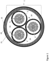
- Figure 1 is a cut-view drawing schematically illustrating a typical construction of a three-phase power cable. As seen on the figure, each electric conductor 2 typically comprises a plurality of strands bundled together. Each bundle of strands is radially encapsulated by an electric insulation system 3.
- the water barrier system 4 (shown as a single layer for the sake of clarity in the figure) is laid onto the electric insulation system 3 of each conductor 2.
- the three electrically insulated and water intrusion protected conductors 2 are bundled together with three spacers 24 as shown on the figure to obtain a circular cross-section.
- the spacers 24 are adapted to fill the space between adjacent electrically insulated and water intrusion protected conductors 2 and provide an overall cylindrical geometry of the cable.
- Said arrangement of three conductors 2 (with insulation 3 and water protection 4) and three spacers 24 constitutes the cable core 1 as indicated by the stapled parenthesis.
- the water barrier system 4 would in this example embodiment typically be laid onto the semiconductive layer 21.
- Figure 2a is a drawing, as seen from above, illustrating a metal 5a foil, having a width wi and a length li, being prepared to be folded around the insulated conductor and form the metal sheath 5 encompassing an electrically insulated 3 conductor 2.
- the length l 1 equals the longitudinal length of the electrically insulated 3 conductor 2
- the width wi equals the outer perimeter (the circumference) of the insulated 3 conductor 2 to enable the opposite ends in the longitudinal direction to contact each other and be welded together when the metal foil 5a is folded around the insulated 3 core 2.
- Figure 2b is a cut-view drawing as seen from the side in and in the direction of the longitudinal centre axis of the conductor illustrated by the stapled line marked A-A' in figure 2a ).
- the figure is a drawing schematically illustrating the process of forming the metal sheath 5 around an electrically insulated 3 conductor 2 just before the folding of the metal foil 5a is fully folded around the insulated 3 conductor 2 such that the opposing longitudinal ends 9, 10 contact each other and joining by welding (not shown on the figures).
- the resulting longitudinal welding seam 6 is illustrated schematically in figure 2c ).
- this embodiment of the electrically insulated conductor comprises a swelling tape 8 laid onto the insulation system 3 of the conductor 2.
- Figure 2d illustrates schematically an example embodiment of how the additional metal layer 7 may be formed by additive manufacturing by successively depositing stripes of metal material onto outer surface of the metal sheath 5 including the longitudinal welding seam 6.
- the method according to the invention may further comprise a drawing, rolling or corrugation process that reduces the overall diameter of the sheath metal 5 with the deposited additional metal layer 7.
- the invention is described in further detail by way of example embodiments of forming a water-barrier system according to the invention using laser powder deposition of a Cu-layer onto a longitudinal welding seam joining two CuNi-plates welded together at opposite ends.
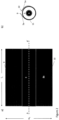
- the first verification test is shown in the photograph in figure 4a ), which shows a section of the front side of the joined CuNi-plates.
- the longitudinal welding seam 6 of the joint is clearly visible on the photograph.
- Two defects on the form of a drilled hole 12 of 1 mm diameter were deliberately introduced in the welding seam 6 and marked with the white arrows.
- the photograph shown in figure 4b shows the front side of the joined CuNi-plates after deposition of the additional metal layer 7.
- the drilled holes are no longer visible.
- the defects have been completely covered by the deposited Cu-layer constituting the additional metal layer.
- the photograph shown in figure 4c shows the back-side of the of the joined CuNi-plates after deposition of the additional metal layer 7 and confirms the result shown in figure 4b ).
- FIG. 5a) to 5c A further verification of the invention is shown in figures 5a) to 5c ) which present a photograph of an additional metal layer 7 according to the invention of copper deposited on top of a laser welded seam 6 joining two metal strips of a CuNi25 alloy.
- the additional metal layer 7 Before the deposition of the additional metal layer 7, there was intentionally made holes in the welding seam 6 ranging from 0.5 to 5 mm in diameter.
- the holes were thereafter plugged by depositing a layer of Cu onto the welded seam including the holes by laser powder deposition using a precursor powder of metallic copper.
- the holes were covered both on a spot basis and the full length - i.e., also areas of the weld where no holes were present.
- the laser powder deposition applied a Trumpf trudisk machine with 1030 nm laser wavelength and 80- 3000 W. The deposition speed was in the range of 3- 10 m/min.
Landscapes
- Engineering & Computer Science (AREA)
- Manufacturing & Machinery (AREA)
- Insulated Conductors (AREA)
Abstract
The present invention relates to a power cable comprising a cable core (1) comprising at least one conductor (2) with an insulation system (3), and a water barrier system (4) encapsulating said cable core (1) and/or said insulation system (3) of each of the at least one conductor (2), wherein said water barrier system (4) comprises a metal sheath (5) encapsulating the cable core (1) and/or the insulation system (3) of each of the at least one conductor (2), and wherein the metal sheath (5) is made by wrapping a metal foil around the cable core (1) and/or the insulation system (3) of each of the at least one conductor (2) and then welding together opposing ends of the wrapped metal foil forming a longitudinal welding seam (6), characterised in that the water barrier system further comprises an additional metal layer (7) deposited onto an outer surface of the metal sheath (5) and covering at least said longitudinal welding seam (6).
Description
- The present invention relates to a power cable having a non-leaded metallic water barrier.
- Electrical high voltage cables contain one or more electrically insulated current carrying conductors at its core section. However, intrusion of humidity or water into the core section may cause electrical breakdown of the insulation system making it vital to keep the current carrying core of high voltage power cables dry. High voltage power cables are therefore typically equipped with a circumferentially arranged water-tight layer sealing off the current carrying parts of the power cable towards ambient moisture/water.
- The water-barrier layer typically comprises a layer of a metal. Lead/lead-alloys are commonly applied. However, lead is a high-density materiel adding significant weight to the cable. The heavy weight induces extra costs in the entire value chain from production, under transport, storage, deployment, and when the cable is discarded after reaching its lifetime. Lead is also a neurotoxic material meeting increasing environmental regulation restrictions. Furthermore, lead has a relatively low fatigue resistance making leaden water barriers less suited for dynamical power cables.
- A known alternative to water barriers of lead is the use of high resistance (non-lead) metallic screens laid around the core and/or the insulated conductors of the power cable and joining opposite ends of the wrapped screen by e.g. welding. However, these alternative water barriers still have an unacceptable risk of failure, especially when producing long cables of several kilometres of length, because it is difficult to identify eventual production failures due to the welding process- in the welding seam such as e.g. pinholes in the metal, welding defects, etc.
- The main objective of the invention is to provide a high-voltage power cable having a lead-free low weight water-barrier around the cable core and/or the conductor(s) of the power cable.
- In the scope of the instant invention, the inventors have now shown that, when applying a high resistance (non-leaded) metallic screen covering the core and/or the insulated conductors of the power cable by being wrapped around and joined by welding, the problem with potential production defects along the welding seam, such as e.g. pinholes in the metal, welding defects etc., may be repaired and/or sealed by utilizing additive manufacturing techniques to deposit a metal layer at least covering identified welding defects in said welding seam, or alternatively covering the entire welded seam of the metallic screen.
- According to a a first aspect, the invention relates to a power cable comprising:
- a cable core comprising at least one conductor with an insulation system encapsulating said conductor, and
- a water barrier system that encapsulating said cable core and/or encapsulating said insulation system of each of the at least one conductor , wherein
- said water barrier system comprises a metal sheath encapsulating the cable core and/or encapsulating the insulation system of each of the at least one conductor,
and wherein - the metal sheath is made by wrapping a metal foil around the cable core and/or the insulation system of each of the at least one conductor and then welding together opposing ends of the wrapped metal foil forming a longitudinal welding seam,
characterised in that - the water barrier system further comprises an additional metal layer deposited onto an outer surface of the metal sheath and covering at least identified welding defects in said longitudinal welding seam.
- In the power cable of the invention, the metal sheath preferably encapsulates:
- the whole cable core; and/or
- the insulation system of the at least one conductor, when only one insulation system is present (around an unique conductor or around several conductors); or each of the insulation systems when several insulation systems are present around several conductors.
- The following description is made with reference to the appended illustrative Figures, which refer to a a specific example of a power cable as shown in
Figure 1 that comprises: - a
cable core 1 comprisingseveral conductors 2 with aninsulation system 3 encapsulating each of saidconductor 2, and - a
water barrier system 4 encapsulating each of theconductors 2 , - said
water barrier system 4 comprisesmetal sheaths 5 encapsulating each of theinsulation system 3 of each of theconductors 2; - each of the
metal sheaths 5 is made by wrapping a metal foil around aninsulation system 3 of aconductor 2 and then welding together opposing ends of the wrapped metal foil forming alongitudinal welding seam 6;
and - the water barrier system further comprises a
metal layer 7 deposited onto an outer surface of each of themetal sheath 5 and covering at least identified welding defects in saidlongitudinal welding seams 6. - The term "longitudinal" as used herein refers to the main direction of the power cable. Namely, a longitudinal direction is parallel with or co-axial with the longitudinal centre axis of the power cable.
- The term "metal sheath" as used herein, refers to the primary water-impenetrable layer of the water-barrier system of the invention. The metal sheath is typically formed by folding and welding together opposite ends of a metal foil such that the resulting metal sheath is laid around to encompass and encapsulate the core and/or the insulated conductors of the power cable. The invention is not tied to use of any specific metal foil to make the metal sheath, except that it should not be made of Pb or a Pb-alloy. The metal foil may be made of any non-lead metal/metal alloy having any thickness known to the skilled person to be suited for use as a metallic screen/water-barrier in power cables. In one example embodiment, the metal foil is either an Al/Al-alloy such as for example an AA1xxx series, an AA5xxx series or an AA6xxx series alloy according to the Aluminum Association Standard, or a Cu/Cu-alloy such as for example pure Cu, a CuNi-alloy or a CuNiSi-alloy, or a Fe/Fe-alloy, such for example stainless alloy SS316 or S32750. The thickness of the metal sheath may in an example embodiment be in one of the following ranges; from 10 to 1000 µm, preferably from 20 to 750 µm, more preferably from 30 to 500 µm, more preferably from 40 to 100 µm, and most preferably from 50 to 75 µm.
- The specific metal layer deposited according to the invention onto an outer surface of the metal sheath (herein-above referred as the layer 7) should at least cover identified defects in the
welding seam 6. Namely, this metal layer may cover one or more local areas on themetal sheath 5 and/or thewelding seam 6. Alternatively, in one embodiment, the metal foil constituting the metal sheath may be shaped into a substantially rectangular metallic layer having a longitudinal centre axis of length l1 and a width wi. The length l1 is preferably equal to the length of the power cable, while the width wi needs to be at least equal to the outer perimeter, p, of thecable core 1 or the electrically insulatedconductor 2 at which themetal heath 5 is to be applied in order to enable encapsulate saidcable core 1 or the electrically insulated 3conductor 2. Alternatively, the width wi, may be larger than the outer perimeter, p, of thecable core 1 or the electrically insulated 3conductor 2, in which case the wrapped/foldedmetal foil 5a will encapsulate thecable core 1 or the electrically insulated 3conductor 2 with some overlap. - The term "opposing ends" as used herein, refers to the longitudinal sides of the metal foil (5a in
figure 2 ) which will be facing each other with or without some overlap when themetal foil 5a it is folded/wrapped around thecable core 1 and/or theinsulation system 3 of each of the at least oneconductor 2 at which themetal sheath 5 is to be formed. - According to the invention, the water-barrier system includes an additional metal layer laid onto and covering at least the welding seam formed when joining the wrapped/folded metal foil to make the metallic screen encompassing and encapsulating the core and/or the insulated conductors of the power cable. In other words, the additional meta layer (e.g. the
metal layer 7 described with reference to the Figures) acts as a reinforcing additional metal layer covering and sealing-off the welding seam which may contain pin holes or other welding defects due to unintentional manufacturing inaccuracies when forming the metal sheath. - The invention is not tied to use of any specific metal in the additional metal layer, except that it should not be made of Pb or a Pb-alloy. Any non-lead metal/metal alloy at any thickness known to the skilled person to be suited for use as metallic screen/water-barrier layer may be applied as the additional metal layer. In one example embodiment, the additional metal layer is either an Al/Al-alloy such as for example an AA1xxx series, an AA5xxx series or an AA6xxx series alloy according to the Aluminium Association Standard, or a Cu/Cu-alloy such as for example pure Cu, a CuNi-alloy or a CuNiSi-alloy, Ti, a Ti-alloy, or a Fe/Fe-alloy, such for example stainless alloy SS316 or S32750. The thickness of the additional metal layer may in an example embodiment be in one of the following ranges; from 2 to 500 µm, preferably from 3 to 300 µm, more preferably from 4 to 150 µm, more preferably from 5 to 125 µm, more preferably from 10 to 100 µm, more preferably from 20 to 75 µm, and most preferably from 30 to 50 µm.
- In one embodiment, the
metal layer 7 may advantageously have a substantially rectangular shape with a longitudinal centre axis of length l2 and a width w2. Thelength 1 is preferably equal to the length of the welding seam to be covered, while the width w2 is preferably in the range from 0.1 to 5 cm, preferably from 0.25 to 4 cm, more preferably from 0.5 to 3 cm, more preferably from 0.75 to 2.5 cm, more preferably from 1 to 2 cm, and most preferably from 1.25 to 1.5 cm. By depositing the additional metal layer such that its longitudinal centre axis becomes substantially co-centric with the longitudinal welding seam of the metallic sheath, the additional metal layer will cover both the welding seam and some of the adjacent outer surface area of the underlying metal sheath. Alternatively, the substantially rectangular additional metallic layer having a longitudinal centre axis of length l2 and a width w2. In one embodiment, the substantially rectangularly shapedadditional metal layer 7 may have a somewhat concave cross-section, i.e. being thickest at its longitudinal centre axis and gradually thinner towards its longitudinal side-edges to better conform with the curvature of themetal sheath 5. In the latter case, the above given ranges for thickness of theadditional metal layer 7 refers to its thickness at its longitudinal centre axis. - The term "electric conductor" as used herein refers to the current carrying inner core of the power cable. The invention may apply any known or conceivable current carrying inner core known to the skilled person being suited to carry/transport electric current, including but not limited to a single strand of an electrically conductive material, a plurality of strands of an electrically conductive material arranged in a bunt, etc. In the latter case of applying an electric conductor comprising a bunt of strands, the space in-between the strands of electrically conductive material may be occupied by a semiconducting filler compound. The electric conductor may in further example embodiments also comprise a semiconducting conductor screen arranged radially around and encompassing the single strand or bunt of strands. Examples of materials being suited as the current carrying strand(s) of the electric conductor of power cables include, but are not limited to; Cu, Cu-alloy, Al, or an Al-alloy. In practice, the electrically conductive material being applied as conductor(s) in power cables may advantageously have an electric conductivity of at least 4.8·106 S/m at 20 °C, preferably of at least 1.0·107 S/m at 20 °C and most preferably of at least 3.6·107 S/m at 20 °C.
- Each conductor of power cables should be individually electrically insulated. This is typically obtained by covering the surface of the conductor by a layer of an electric insulating material, i.e. to make the conductor being sheathed in the electrically insulating material. The invention may apply any known or conceivable material, including dielectric materials, known to the skilled person as being suited as insulation of the current carrying conductor(s) of power cables. In practice the electric conductivity of the material being applied as insulation may advantageously have an electric conductivity of less than 10-14 S/m at 20 °C, preferably less than 10-16 S/m at 20 °C, preferably less than 10-18 S/m at 20 °C, and most preferably less than 10-20 S/m at 20 °C. Examples of materials suited for being applied to form the electric insulation of the conductor(s) include, but are not limited to; ethylene propylene rubber (EPR), ethylene propylene diene monomer (EDPM), rubber, polyethylene (EP), polypropylene (PP), polyurethane (PUR), cross-linked polyethylene (XLPE), and mass-impregnated (MI) paper. The insulation effect of the insulating material depends on the thickness of the layer of insulating material. In general, the higher voltage of the electric current in the conductor, the more insulation is needed. The determination of amount of insulating material required to electrically insulate a conductor is within the ordinary skills of the person skilled in the art.
- The term "cable core" as used herein refers to the interior part of power cables containing the electrically insulated current carrying conductor(s) of the power cable. If more than one cable core is present, the cable core usually also contains one or more spacers arranged and adapted to provide the cable core with a circular cross-section. The cable core may also further comprise signal cables, optic fibres, and/or any other component known to the skilled person suited for being located in a cable core. Thus, the term "a water barrier system encapsulating said cable core" as used herein means that the water barrier system is laid onto and around the outer surface of the cable core to form a watertight enclosure of the interior of the cable core preventing water and/or moisture from penetrating into the cable core.
- In a second aspect, the invention relates to a method of forming a water barrier system (identified by
reference 4 in the Figures) on a cable core (1) and/or an electrically insulated conductor (2 with an insulation system 3) of a power cable, wherein the method comprises:
forming a metal sheath (5) encapsulating the cable core (1) and/or the insulation system (3) of each of the at least one conductor (2) by: - folding/wrapping a metal foil around the cable core (1) and/or the insulation system (3) of each of the at least one conductor (2), and
- welding together opposite ends of the folded/wrapped metal foil forming a longitudinal welding seam (6),
- The invention according to the first and/or second aspect is not tied to use of any specific method of forming/depositing the metal layer (referred as the
layer 7 in the Figurs) onto themetal sheath 5 as long as theadditional metal layer 7 is made to at least covering thelongitudinal welding seam 6 and to make a water impenetrable reinforcement/seal of thelongitudinal welding seam 6. A well suited and preferred method is making/depositing theadditional metal layer 7 by additive manufacturing (AM), which also may be labelled as 3D-printing in the literature. AM works by a computer controlled process that builds the three-dimensional objects onto a substrate by successively depositing strips or layers of material until the object is formed. In this manner, a dense and compact (continuous) sheet or layer of the additional metal is laid onto and firmly attached to theunderlying metal sheath 5 andwelding seam 6 which effectively closes and seals-off eventual welding defects in thelongitudinal welding seam 6. - A particularly suited and preferred additive manufacturing technology is cold spray additive manufacturing, which may build the additional metal layer by blowing a powder of the additional metal by a high-velocity compressed gas stream onto the deposition area of the outer surface of the
metal sheath 5 and/or thewelding seam 6 causing the powder upon impingement on the target surface to deform and bond together to a layer of the additional metal. An advantage of cold spraying is that the physical and chemical properties of the underlying substrate is mainly unaffected due to a relatively limited heating since no melting is involved. The formedadditional metal layer 7 obtains also relatively strong mechanical properties by attaining a typical cold-worked microstructure. - Alternatively, another particularly suited and preferred additive manufacturing technology is direct energy deposition additive manufacturing in which an object is built by successive deposition of strips of a material being melted (and subsequently solidified) upon deposition by a thermal energy source. The invention may apply any known direct energy deposition, but an especially preferred method of forming the
additional metal layer 7 is laser powder deposition in which deposition is achieved by combining a focused spray of a powder of the additional metal to the point or region of interest onto the outer surface of themetal sheath 5 and/or thewelding seam 6 and melting the powder of the additional metal by a high power laser. This technique is a relatively common technique within additive manufacturing known and mastered by the person skilled in the. The technique is particularly suitable for forming the additional metal layer of the present invention as the powder can readily penetrate and cover potential holes in the underlying metal sheath. The powder may constitute an alloy or alloy constituents that mix when re-melted. Relevant powder materials include the same metals and alloys as listed above for the additional metal layer. - The principle of laser powder deposition is illustrated schematically in
figure 3 (the figure is a facsimilefigure 1 of [ref 1]). A nozzle directs a gas flow containing entrained particles of the material to be deposited onto a deposition area of a substrate or workpiece under construction where the particles are heated and melted by a laser beam to form a melt pool on the substrate/workpiece. By mowing the nozzle and substrate/workpiece relative to each other, typically in a straight line, the deposition area/melt pool moves correspondingly on the substrate/workpiece and causes the particulate material to be continuously deposited and melted in a corresponding pattern. The part of the molten pool which is left behind by the moving nozzle and laser beam will rapidly solidify. If the nozzle moves in a straight, the deposited material will form a continuous stripe onto the substrate/- workpiece. A plate or layer of material may be formed by depositing a number of parallel stripes adjacent to each other. When applying laser powder deposition to form the additional metal layer according to the invention, the substrate may advantageously be themetal sheath 5 including thelongitudinal welding seam 6. - In one embodiment the method according to the invention may further comprise depositing an adhesive layer, e.g. a polyethylene, onto the
sheath metal 5 and the depositedadditional metal layer 7 and then depositing a polymeric sheath onto the adhesive layer. - The water barrier system according to the first and/or the additional aspect of the invention, may be applied to encapsulate the cable core, alternatively encapsulating the cable core and each of the at least one electrically insulated conductors, or alternatively (only) encapsulating each of the at least one electrically insulated conductors of the power cable.
Figure 1 is a cut-view drawing schematically illustrating a typical construction of a three-phase power cable. As seen on the figure, eachelectric conductor 2 typically comprises a plurality of strands bundled together. Each bundle of strands is radially encapsulated by anelectric insulation system 3. In this example embodiment, the water barrier system 4 (shown as a single layer for the sake of clarity in the figure) is laid onto theelectric insulation system 3 of eachconductor 2. The three electrically insulated and water intrusion protectedconductors 2 are bundled together with threespacers 24 as shown on the figure to obtain a circular cross-section. I.e. thespacers 24 are adapted to fill the space between adjacent electrically insulated and water intrusion protectedconductors 2 and provide an overall cylindrical geometry of the cable. Said arrangement of three conductors 2 (withinsulation 3 and water protection 4) and threespacers 24 constitutes thecable core 1 as indicated by the stapled parenthesis. Typically, there will be asemiconductive layer 21 onto the cable core to conduct capacitive charges induced in the cable, anarmoring 22 and anouter polymer sheathing 23. In the case of applying thewater barrier system 4 according to the invention on thecable core 1, thewater barrier system 4 would in this example embodiment typically be laid onto thesemiconductive layer 21. - An example embodiment of the process for manufacturing a
water system 4 according to the invention is illustrated schematically infigures 2a) to 2d ). -
Figure 2a ) is a drawing, as seen from above, illustrating ametal 5a foil, having a width wi and a length li, being prepared to be folded around the insulated conductor and form themetal sheath 5 encompassing an electrically insulated 3conductor 2. The length l1 equals the longitudinal length of the electrically insulated 3conductor 2, while the width wi equals the outer perimeter (the circumference) of the insulated 3conductor 2 to enable the opposite ends in the longitudinal direction to contact each other and be welded together when themetal foil 5a is folded around the insulated 3core 2. -
Figure 2b ) is a cut-view drawing as seen from the side in and in the direction of the longitudinal centre axis of the conductor illustrated by the stapled line marked A-A' infigure 2a ). The figure is a drawing schematically illustrating the process of forming themetal sheath 5 around an electrically insulated 3conductor 2 just before the folding of themetal foil 5a is fully folded around the insulated 3conductor 2 such that the opposinglongitudinal ends longitudinal welding seam 6 is illustrated schematically infigure 2c ). As seen fromfigure 2b ), this embodiment of the electrically insulated conductor comprises a swellingtape 8 laid onto theinsulation system 3 of theconductor 2. -
Figure 2d ) illustrates schematically an example embodiment of how theadditional metal layer 7 may be formed by additive manufacturing by successively depositing stripes of metal material onto outer surface of themetal sheath 5 including thelongitudinal welding seam 6. - In one embodiment the method according to the invention may further comprise a drawing, rolling or corrugation process that reduces the overall diameter of the
sheath metal 5 with the depositedadditional metal layer 7. -
-
Figure 1 is a cut view drawing illustrating the typical construction of a three-phase power cable. -
Figures 2a) to 2d ) are drawings schematically illustrating an example embodiment of forming a water-barrier system according to the invention on a conductor. -
Figure 3 is a facsimile offigure 1 of [ref 1] illustrating a typical embodiment of laser powder deposition. -
Figures 4a) to 4c ) are photographs of a verification experiment on two CuNi plates joined by welding followed by deposition of Cu as an additional metal layer according to the invention. -
Figures 5a) to 5c ) are photographs of a verification experiment where two plates of a CuNi25 alloy were welded together and received a copper layer made by laser powder deposition. - The invention is described in further detail by way of example embodiments of forming a water-barrier system according to the invention using laser powder deposition of a Cu-layer onto a longitudinal welding seam joining two CuNi-plates welded together at opposite ends.
- The first verification test is shown in the photograph in
figure 4a ), which shows a section of the front side of the joined CuNi-plates. Thelongitudinal welding seam 6 of the joint is clearly visible on the photograph. Two defects on the form of a drilledhole 12 of 1 mm diameter were deliberately introduced in thewelding seam 6 and marked with the white arrows. - The photograph shown in
figure 4b ) shows the front side of the joined CuNi-plates after deposition of theadditional metal layer 7. The drilled holes are no longer visible. The defects have been completely covered by the deposited Cu-layer constituting the additional metal layer. - The photograph shown in
figure 4c ) shows the back-side of the of the joined CuNi-plates after deposition of theadditional metal layer 7 and confirms the result shown infigure 4b ). - A further verification of the invention is shown in
figures 5a) to 5c ) which present a photograph of anadditional metal layer 7 according to the invention of copper deposited on top of a laser weldedseam 6 joining two metal strips of a CuNi25 alloy. - Before the deposition of the
additional metal layer 7, there was intentionally made holes in thewelding seam 6 ranging from 0.5 to 5 mm in diameter. The holes were thereafter plugged by depositing a layer of Cu onto the welded seam including the holes by laser powder deposition using a precursor powder of metallic copper. The holes were covered both on a spot basis and the full length - i.e., also areas of the weld where no holes were present. The laser powder deposition applied a Trumpf trudisk machine with 1030 nm laser wavelength and 80- 3000 W. The deposition speed was in the range of 3- 10 m/min. - As seen on the photographs of
figures 5a) to 5c ), the holes in the welded seams are effectively plugged. In this test, theadditional metal layer 7 was only deposited on a section of the weldedseam 6 since the test was aimed at proof of concept of the present invention. - Furthermore, it is assumed that a power material consisting of Cu-Ni alloy would improve the situation due to improved laser absorption.
-
depositing a metal layer (7) onto an outer surface of the
Claims (19)
- A power cable comprising:a cable core (1) comprising at least one conductor (2) with an insulation system (3) encapsulating said conductor (2), anda water barrier system (4) encapsulating said cable core (1) and/or encapsulating said insulation system (3) of each of the at least one conductor (2), whereinsaid water barrier system (4) comprises a metal sheath (5) encapsulating the cable core (1) and/or encapsulating the insulation system (3) of each of the at least one conductor (2),
and whereinthe metal sheath (5) is made by wrapping a metal foil around the cable core (1) and/or the insulation system (3) of each of the at least one conductor (2) and then welding together opposing ends of the wrapped metal foil forming a longitudinal welding seam (6),
characterised in thatthe water barrier system further comprises an additional metal layer (7) deposited onto an outer surface of the metal sheath (5) and covering at least identified welding defects in said longitudinal welding seam (6). - The power cable according to claim 1, wherein the metal foil constituting the metal sheath (5) is made of either:aluminium,an aluminium alloy of the AA1xxx series, AA5xxx series or the AA6xxx series according to the Aluminium Association Standard,copper,a copper-alloy,a CuNi-alloy,a CuNiSi-alloy,iron,a Fe-alloy,stainless steel alloy SS316,
orstainless steel alloy S32750. - The power cable according to claim 1 or 2, wherein the thickness of the metal foil constituting the metal sheath (5) is in one of the following ranges; from 10 to 1000 µm, preferably from 20 to 750 µm, more preferably from 30 to 500 µm, more preferably from 40 to 100 µm, and most preferably from 50 to 75 µm.
- The power cable according to any preceding claim, wherein the additional metal layer (7) is made of either:aluminium,an aluminium alloy of the AA1xxx series, AA5xxx series or the AA6xxx series,copper,a copper-alloy,a CuNi-alloy,a CuNiSi-alloy,iron,a Fe-alloy,Ti,a Ti-alloy,stainless steel alloy SS316,
orstainless steel alloy S32750. - The power cable according to claim 4, wherein the thickness of the additional metal layer (7) is in one of the following ranges; from 2 to 500 µm, preferably from 3 to 300 µm, more preferably from 4 to 150 µm, more preferably from 5 to 125 µm, more preferably from 10 to 100 µm, more preferably from 20 to 75 µm, and most preferably from 30 to 50 µm.
- The power cable according to any preceding claim, wherein the additional metal layer (7) is made to cover the entire welding seam (6) of the metal sheath (5) and is shaped into a substantially rectangular metallic layer having a longitudinal centre axis of length l2 and a width w2, where the length lz is equal to the length of the welding seam (6), and the width w2 is in the range from 0.1 to 5 cm, preferably from 0.25 to 4 cm, more preferably from 0.5 to 3 cm, more preferably from 0.75 to 2.5 cm, more preferably from 1 to 2 cm, and most preferably from 1.25 to 1.5 cm.
- The power cable according to claim 6, wherein the additional metal layer (7) is laid onto the outer surface of the metal sheath (5) such that its longitudinal centre axis is co-centric with the longitudinal welding seam (6) of the metallic sheath (5).
- The power cable according to claim 7, wherein the additional metal layer (7) have a somewhat concave cross-section by being thickest at a longitudinal centre axis and gradually thinner towards its longitudinal side-edges.
- The power cable according to any preceding claim, wherein the additional metal layer (7) is deposited by additive manufacturing.
- The power cable according to claim 9, wherein the additional metal layer (7) is deposited by cold spray additive manufacturing.
- The power cable according to claim 9, wherein the additional metal layer (7) is deposited by direct energy deposition additive manufacturing.
- The power cable according to claim 11, wherein the direct energy deposition additive manufacturing is laser powder deposition.
- A method of forming a water barrier system (4) on a cable core (1) and/or an electrically insulated (3) conductor (2) of a power cable, wherein the method comprises:
forming a metal sheath (5) encapsulating the cable core (1) and/or the insulation system (3) of each of the at least one conductor (2) by:folding/wrapping a metal foil around the cable core (1) and/or the insulation system (3) of each of the at least one conductor (2), andwelding together opposite ends of the folded/wrapped metal foil forming a longitudinal welding seam (6),characterised in that the method further discloses:
depositing an additional metal layer (7) onto an outer surface of the metal sheath (5) which at least covers the longitudinal welding seam (6). - The method according to claim 13, wherein the additional metal layer (7) is deposited onto the metal sheath (5) and/or the longitudinal welding seam (6) by additive manufacturing.
- The method according to claim 13 or 14, wherein the additional metal layer (7) is deposited onto the metal sheath (5) and/or the longitudinal welding seam (6) by cold spray additive manufacturing.
- The method according to any of claims 13 to 15, wherein the additional metal layer (7) is deposited onto the metal sheath (5) and/or the longitudinal welding seam (6) by direct energy deposition additive manufacturing.
- The method according to claim 16, wherein the direct energy deposition additive manufacturing is laser powder deposition.
- The method according to any of claims 13 to 17, wherein the method further comprises a drawing, rolling or corrugation process that reduces the overall diameter of the sheath metal (5) with the deposited additional metal layer (7).
- The method according to any of claims 13 to 18, wherein the method further comprises depositing a polymeric sheath into the sheath metal (5) and the deposited additional metal layer (7).
Priority Applications (1)
| Application Number | Priority Date | Filing Date | Title |
|---|---|---|---|
| EP23315176.0A EP4462451A1 (en) | 2023-05-09 | 2023-05-09 | Power cable with lead-free metal water barrier |
Applications Claiming Priority (1)
| Application Number | Priority Date | Filing Date | Title |
|---|---|---|---|
| EP23315176.0A EP4462451A1 (en) | 2023-05-09 | 2023-05-09 | Power cable with lead-free metal water barrier |
Publications (1)
| Publication Number | Publication Date |
|---|---|
| EP4462451A1 true EP4462451A1 (en) | 2024-11-13 |
Family
ID=86692978
Family Applications (1)
| Application Number | Title | Priority Date | Filing Date |
|---|---|---|---|
| EP23315176.0A Pending EP4462451A1 (en) | 2023-05-09 | 2023-05-09 | Power cable with lead-free metal water barrier |
Country Status (1)
| Country | Link |
|---|---|
| EP (1) | EP4462451A1 (en) |
Citations (4)
| Publication number | Priority date | Publication date | Assignee | Title |
|---|---|---|---|---|
| DE3312551A1 (en) * | 1983-04-05 | 1984-10-11 | Siemens AG, 1000 Berlin und 8000 München | Method of repairing welding defects on external copper conductors of coaxial cables or coaxial lines |
| US20090068495A1 (en) * | 2007-09-06 | 2009-03-12 | Dembowski Thaddeus J | Methods and Systems for Re-Metallizing Weld Area in Steel Electrical Conduit |
| EP3014632A1 (en) * | 2013-06-27 | 2016-05-04 | Prysmian S.p.A. | Method of manufacturing power cables and related power cable |
| US20210210253A1 (en) * | 2018-05-25 | 2021-07-08 | Prysmian S.P.A. | High voltage power cable with fatigue-resistant water barrier |
-
2023
- 2023-05-09 EP EP23315176.0A patent/EP4462451A1/en active Pending
Patent Citations (4)
| Publication number | Priority date | Publication date | Assignee | Title |
|---|---|---|---|---|
| DE3312551A1 (en) * | 1983-04-05 | 1984-10-11 | Siemens AG, 1000 Berlin und 8000 München | Method of repairing welding defects on external copper conductors of coaxial cables or coaxial lines |
| US20090068495A1 (en) * | 2007-09-06 | 2009-03-12 | Dembowski Thaddeus J | Methods and Systems for Re-Metallizing Weld Area in Steel Electrical Conduit |
| EP3014632A1 (en) * | 2013-06-27 | 2016-05-04 | Prysmian S.p.A. | Method of manufacturing power cables and related power cable |
| US20210210253A1 (en) * | 2018-05-25 | 2021-07-08 | Prysmian S.P.A. | High voltage power cable with fatigue-resistant water barrier |
Non-Patent Citations (1)
| Title |
|---|
| LIM ET AL.: "Selection of effective manufacturing conditions for directed energy deposition process using machine learning methods", SCIENTIFIC, vol. 11, no. 24169, 2021, Retrieved from the Internet <URL:https://www.nature.com/articles/s41598-021-03622-z> |
Similar Documents
| Publication | Publication Date | Title |
|---|---|---|
| US11631505B2 (en) | CuNiSi alloy cable sheathing | |
| EP3792938B1 (en) | Process for manufacturing a submarine power cable and power cable so manufactured | |
| EP3069354B1 (en) | Process of manufacturing power cables and related power cable | |
| EP4016552B1 (en) | Lead-free water barrier | |
| EP4015208B1 (en) | Laminate water barrier | |
| EP3014632B1 (en) | Method of manufacturing power cables and related power cable | |
| US11837386B2 (en) | Reinforced water barrier over a joint | |
| EP4068309A1 (en) | Low resistance pe sheath with combined adhesive and mechanical properties | |
| EP4141893A1 (en) | Radially and longitudinally conductive water barrier assembly | |
| US12417863B2 (en) | Power cable with multiple water barriers | |
| EP4456088A1 (en) | Power cable with a sealed laminate water barrier | |
| EP4418284B1 (en) | Submarine power cable with longitudinal tape |
Legal Events
| Date | Code | Title | Description |
|---|---|---|---|
| PUAI | Public reference made under article 153(3) epc to a published international application that has entered the european phase |
Free format text: ORIGINAL CODE: 0009012 |
|
| STAA | Information on the status of an ep patent application or granted ep patent |
Free format text: STATUS: THE APPLICATION HAS BEEN PUBLISHED |
|
| AK | Designated contracting states |
Kind code of ref document: A1 Designated state(s): AL AT BE BG CH CY CZ DE DK EE ES FI FR GB GR HR HU IE IS IT LI LT LU LV MC ME MK MT NL NO PL PT RO RS SE SI SK SM TR |
|
| STAA | Information on the status of an ep patent application or granted ep patent |
Free format text: STATUS: REQUEST FOR EXAMINATION WAS MADE |
|
| 17P | Request for examination filed |
Effective date: 20250408 |