EP4462447A1 - Method and apparatus for dismantling nuclear power plant - Google Patents
Method and apparatus for dismantling nuclear power plant Download PDFInfo
- Publication number
- EP4462447A1 EP4462447A1 EP23737330.3A EP23737330A EP4462447A1 EP 4462447 A1 EP4462447 A1 EP 4462447A1 EP 23737330 A EP23737330 A EP 23737330A EP 4462447 A1 EP4462447 A1 EP 4462447A1
- Authority
- EP
- European Patent Office
- Prior art keywords
- nuclear reactor
- fire
- fire extinguishing
- frame unit
- power plant
- Prior art date
- Legal status (The legal status is an assumption and is not a legal conclusion. Google has not performed a legal analysis and makes no representation as to the accuracy of the status listed.)
- Pending
Links
Images


Classifications
-
- A—HUMAN NECESSITIES
- A62—LIFE-SAVING; FIRE-FIGHTING
- A62C—FIRE-FIGHTING
- A62C35/00—Permanently-installed equipment
- A62C35/02—Permanently-installed equipment with containers for delivering the extinguishing substance
- A62C35/10—Containers destroyed or opened by flames or heat
-
- G—PHYSICS
- G21—NUCLEAR PHYSICS; NUCLEAR ENGINEERING
- G21C—NUCLEAR REACTORS
- G21C19/00—Arrangements for treating, for handling, or for facilitating the handling of, fuel or other materials which are used within the reactor, e.g. within its pressure vessel
- G21C19/34—Apparatus or processes for dismantling nuclear fuel, e.g. before reprocessing ; Apparatus or processes for dismantling strings of spent fuel elements
- G21C19/36—Mechanical means only
-
- G—PHYSICS
- G21—NUCLEAR PHYSICS; NUCLEAR ENGINEERING
- G21D—NUCLEAR POWER PLANT
- G21D1/00—Details of nuclear power plant
- G21D1/003—Nuclear facilities decommissioning arrangements
-
- G—PHYSICS
- G21—NUCLEAR PHYSICS; NUCLEAR ENGINEERING
- G21C—NUCLEAR REACTORS
- G21C9/00—Emergency protection arrangements structurally associated with the reactor, e.g. safety valves provided with pressure equalisation devices
- G21C9/04—Means for suppressing fires ; Earthquake protection
-
- Y—GENERAL TAGGING OF NEW TECHNOLOGICAL DEVELOPMENTS; GENERAL TAGGING OF CROSS-SECTIONAL TECHNOLOGIES SPANNING OVER SEVERAL SECTIONS OF THE IPC; TECHNICAL SUBJECTS COVERED BY FORMER USPC CROSS-REFERENCE ART COLLECTIONS [XRACs] AND DIGESTS
- Y02—TECHNOLOGIES OR APPLICATIONS FOR MITIGATION OR ADAPTATION AGAINST CLIMATE CHANGE
- Y02E—REDUCTION OF GREENHOUSE GAS [GHG] EMISSIONS, RELATED TO ENERGY GENERATION, TRANSMISSION OR DISTRIBUTION
- Y02E30/00—Energy generation of nuclear origin
Definitions
- the present disclosure relates to a nuclear power plant dismantling method and apparatus.
- aspects of the present disclosure provide a nuclear power plant dismantling apparatus and method capable of securing safety against a fire in performing thermal cutting as nuclear power plant dismantling work.
- aspects of the present disclosure also provide a nuclear power plant dismantling apparatus and method capable of allowing extinguishment to be automatically performed at a fire occurrence site in the event of fire.
- aspects of the present disclosure also provide a nuclear power plant dismantling apparatus and method provided with a fire extinguishing structure capable of allowing extinguishment to be stably performed without interference with surrounding systems in a general operating environment.
- a nuclear power plant dismantling method including: selecting a nuclear reactor to be dismantled; and performing nuclear power plant dismantling work on the nuclear reactor through a nuclear reactor dismantling apparatus, wherein the nuclear reactor dismantling apparatus includes: a frame unit shielding the nuclear reactor to prevent contaminants in the nuclear reactor from being released to the outside; a cutting module provided on the frame unit and performing cutting work on the nuclear reactor; a fire extinguishing module provided on the frame unit, and melted by a heat source based on a fire to automatically supply a fire extinguishing fluid positioned therein to the outside when the fire occurs in the nuclear reactor.
- the frame unit may include an upper structure portion and a lower structure portion facing the upper structure portion, and a plurality of fire extinguishing modules may be provided between the upper structure portion and the lower structure portion, and supply the fire extinguishing fluid to a fire occurrence side where the fire occurs in response to the heat source.
- the lower structure portion of the frame unit may be provided as a ring-shaped body surrounding a peripheral portion of the nuclear reactor, and the plurality of fire extinguishing modules may be disposed on a peripheral portion of the lower structure portion, and each supply the fire extinguishing fluid to the fire occurrence side based on the heat source.
- the fire extinguishing module may include: an outer cylindrical body including a hollow metal material; and an inner cylindrical body accommodated inside the tubular portion and filled with the fire extinguishing fluid, the outer cylindrical body may have a cut portion formed by cutting at least a portion of a peripheral portion of an outer peripheral surface thereof in a horizontal direction or a vertical direction, and when the inner cylindrical body is melted in response to the fire, the fire extinguishing fluid may be supplied to the outside through the cut portion.
- a nuclear power plant dismantling apparatus including: a frame unit shielding a nuclear reactor to prevent contaminants in the nuclear reactor from being released to the outside; a cutting module provided on the frame unit and performing cutting work on the nuclear reactor; and a fire extinguishing module provided on the frame unit, and melted by a heat source based on a fire to automatically supply a fire extinguishing fluid positioned therein to the outside when the fire occurs in the nuclear reactor.
- the nuclear power plant dismantling method and apparatus according to the present disclosure as described above have one or more of the following effects.
- the present disclosure may secure safety against a fire in performing thermal cutting as nuclear power plant dismantling work.
- the present disclosure may allow extinguishment to be automatically performed at a fire occurrence site in the event of fire.
- the present disclosure may allow extinguishment to be stably performed without interference with surrounding systems in a general operating environment.
- a nuclear power plant dismantling apparatus 100 includes a frame unit 110, a cutting module 120, a link fixing module 130, a purging module 140, a fire extinguishing module 150, a gas concentration analysis module 160, and a suction module 170.
- the frame unit 110 includes an upper structure portion 111 and a lower structure portion 112.
- the link fixing module 130 includes compartments 131, 132, and 133.
- the compartments 131, 132, and 133 include a first compartment 131, a second compartment 132, and a third compartment 133.
- the purging module 140 includes a first purging module 141, a second purging module 142, and a third purging module 143.
- the fire extinguishing module 150 includes an outer cylindrical body 151 and an inner cylindrical body 152.
- the frame unit 110 is used to shield the nuclear reactor 10 to prevent contaminants in the nuclear reactor 10 from being released to the outside.
- the frame unit 110 is provided as a structure seated on an upper circumferential portion of the nuclear reactor 10 and having a predetermined shape.
- the cutting module 120 is provided on the frame unit 110 and performs cutting work on the nuclear reactor 10.
- the link fixing module 130 has a hollow area S1 formed therein.
- the link fixing module 130 enters an internal area M1 of the nuclear reactor 10 to link the frame unit 110 and the nuclear reactor 10 with each other.
- the link may include various portions such as a physical connection and a functional operation.
- the purging module 140 enters the hollow area S1 of the link fixing module 130.
- the purging module 140 enters the hollow area S1, and then performs purging on the inside of the nuclear reactor 10 in order to secure safety in the cutting work.
- the compartments 131, 132, and 133 compartment the link fixing module 130 into a plurality of portions in a height direction.
- the first compartment 131 of the compartments 131, 132, and 133 is positioned in the height direction of the link fixing module 130, and forms a first area S11 for communication with the internal area M1.
- the second compartment 132 of the compartments 131, 132, and 133 is positioned in the height direction of the link fixing module 130, and forms a second area S12 for communication with the internal area M1 with the first compartment 131.
- the third compartment 133 of the compartments 131, 132, and 133 is positioned in the height direction of the link fixing module 130, and forms a third area S3 for communication with the internal area M1 with the second compartment 132.
- the purging module 140 performs purging on the internal area M1 of the nuclear reactor 10 via the first area S11 to the third area S3.
- the first purging module 141 of the purging module 140 enters the third area S3 and supplies a first purging gas.
- the second purging module 142 of the purging module 140 enters the second area S12 via the third compartment 133 and supplies a second purging gas to the second area S12.
- the third purging module 143 of the purging module 140 enters the first area S11 via the third compartment 133 and the second compartment 132 and supplies a third purging gas to the first area S11.
- the purging module 140 controls a purging level of the internal area M1 of the nuclear reactor 10 based on selective jetting of the first to third purging gases.
- the first to third purging gases may be the same as each other or at least one of the first to third purging gases may be different from the others of the first to third purging gases.
- the link fixing module 130 has a plurality of through holes TH formed in a peripheral surface surrounding the first area S11 to the third area S 13.
- the purging module 140 performs the purging on the internal area M1 of the nuclear reactor 10 by jetting the first to third purging gases based on the through holes TH.
- the first purging gas of the first purging module 141 enters a first internal area M11 corresponding to the first area S11 in the internal area M1 to purge the nuclear reactor 10.
- the second purging gas of the second purging module 142 enters a second internal area M12 corresponding to the second area S12 in the internal area M1 to purge the nuclear reactor 10.
- the third purging gas of the third purging module 143 enters a third internal area M13 corresponding to the third area S3 in the internal area M1 to purge the nuclear reactor 10.
- the upper structure portion 111 of the frame unit 110 is provided in a predetermined shape.
- the lower structure portion 112 of the frame unit 110 is provided to face the upper structure portion 111.
- Each of the upper structure portion 111 and the lower structure portion 112 is provided to have a cross-sectional shape such as a quadrangular shape, a polygonal shape, a circular shape, or an elliptical shape.
- a single cutting module 120 or a plurality of cutting modules 120 are provided on the frame unit 110 and perform cutting work on the nuclear reactor 10.
- a plurality of fire extinguishing modules 150 are provided between the upper structure portion 111 and the lower structure portion 112.
- the fire extinguishing module 150 serves to supply the fire extinguishing fluid L to a fire occurrence side where the fire occurs in response to the heat source.
- the fire extinguishing module 150 is provided on the frame unit 110, and when the fire occurs in the nuclear reactor 10, the fire extinguishing module 150 is melted by a heat source based on the fire to allow the fire extinguishing fluid L positioned therein is automatically supplied to the outside.
- the lower structure portion 112 of the frame unit 110 described above is provided as a ring-shaped body surrounding a peripheral portion of the nuclear reactor 10.
- the plurality of fire extinguishing module 150 are disposed on a peripheral portion of the lower structure portion 112.
- the fire extinguishing modules 150 each supply the fire extinguishing fluid L to the fire occurrence side based on the heat source.
- the outer cylindrical body 151 of the fire extinguishing module 150 includes a hollow metal material.
- the inner cylindrical body 152 of the fire extinguishing module 150 is accommodated inside the tubular portion.
- the inner cylindrical body 152 is filled with the fire extinguishing fluid L.
- the outer cylindrical body 151 has a cut portion formed by cutting at least a portion of a peripheral portion of an outer peripheral surface thereof in a horizontal direction or a vertical direction.
- At least a portion of the inner cylindrical body 152 is melted in response to the fire. Through such melting, the fire extinguishing fluid L is supplied to the outside of the outer cylindrical body 151 through the cut portion.
- the gas concentration analysis module 160 is provided at at least one position of the frame unit 110 and the nuclear reactor 10 or provided at a portion where the frame unit 110 and the nuclear reactor 10 are adjacent to each other and meet.
- the necessity for purging by the purging module 140 may be grasped and the purging may be performed.
- it is possible to manage an operation of the purging module by continuously grasping whether or not the purging has been properly performed.
- the suction module 170 corresponds to the purging module 140 and sucks the gas discharged through the purging module 140. To this end, the suction module 170 is provided on the frame unit 110 and the nuclear reactor 10.
- the suction module 170 may move between the frame unit 110 and the nuclear reactor 10, and may perform a suction operation.
- the suction module 170 may be provided to be movable up and down in a similar manner to the purging module 140.
- a nuclear reactor 10 to be dismantled is selected.
- Nuclear power plant dismantling work is performed on the nuclear reactor 10 through the nuclear reactor dismantling apparatus 100.
- the nuclear reactor dismantling apparatus 100 is provided with the frame unit 110 shielding the nuclear reactor 10 to prevent contaminants in the nuclear reactor 10 from being released to the outside.
- Such a nuclear reactor dismantling apparatus 100 includes a function for lifting the nuclear reactor.
- the cutting module 120 is provided on the frame unit 110 and performs cutting work on the nuclear reactor 10.
- the link fixing module 130 having a bar shape enters the internal space M1 of the nuclear reactor 10 to link the frame unit 110 and the nuclear reactor 10 with each other.
- Such a link fixing module 130 has the hollow area S1 formed therein. Meanwhile, the purging module 140 enters the hollow area S1 of the link fixing module 130, and performs purging on the inside of the nuclear reactor 10 in order to secure safety in the cutting work.
- the fire extinguishing module 150 is provided on the frame unit 110.
- the fire extinguishing module 150 is melted by a heat source based on the fire. Through such melting, the fire extinguishing fluid L positioned in the fire extinguishing module 150 is automatically supplied to the outside.
Landscapes
- Physics & Mathematics (AREA)
- Engineering & Computer Science (AREA)
- Plasma & Fusion (AREA)
- General Engineering & Computer Science (AREA)
- High Energy & Nuclear Physics (AREA)
- Business, Economics & Management (AREA)
- Emergency Management (AREA)
- Health & Medical Sciences (AREA)
- Public Health (AREA)
- Structure Of Emergency Protection For Nuclear Reactors (AREA)
Abstract
Description
- The present disclosure relates to a nuclear power plant dismantling method and apparatus.
- In dismantling a radioactive pressure vessel of a nuclear power plant, cutting and dismantling is performed using a thermal cutting method. In such a case, an oxy-propane torch has been used, but fire surveillance and fire extinguishing equipment have not been disposed. Accordingly, there is a problem that it is not easy to secure safety against a fire during a cutting and dismantling process using the thermal cutting method.
- Aspects of the present disclosure provide a nuclear power plant dismantling apparatus and method capable of securing safety against a fire in performing thermal cutting as nuclear power plant dismantling work.
- Aspects of the present disclosure also provide a nuclear power plant dismantling apparatus and method capable of allowing extinguishment to be automatically performed at a fire occurrence site in the event of fire.
- Aspects of the present disclosure also provide a nuclear power plant dismantling apparatus and method provided with a fire extinguishing structure capable of allowing extinguishment to be stably performed without interference with surrounding systems in a general operating environment.
- However, aspects of the present disclosure are not restricted to those set forth herein. The above and other aspects of the present disclosure will become more apparent to one of ordinary skill in the art to which the present disclosure pertains by referencing the detailed description of the present disclosure given below.
- According to an aspect of the present disclosure, there is provided a nuclear power plant dismantling method including: selecting a nuclear reactor to be dismantled; and performing nuclear power plant dismantling work on the nuclear reactor through a nuclear reactor dismantling apparatus, wherein the nuclear reactor dismantling apparatus includes: a frame unit shielding the nuclear reactor to prevent contaminants in the nuclear reactor from being released to the outside; a cutting module provided on the frame unit and performing cutting work on the nuclear reactor; a fire extinguishing module provided on the frame unit, and melted by a heat source based on a fire to automatically supply a fire extinguishing fluid positioned therein to the outside when the fire occurs in the nuclear reactor.
- The frame unit may include an upper structure portion and a lower structure portion facing the upper structure portion, and a plurality of fire extinguishing modules may be provided between the upper structure portion and the lower structure portion, and supply the fire extinguishing fluid to a fire occurrence side where the fire occurs in response to the heat source.
- The lower structure portion of the frame unit may be provided as a ring-shaped body surrounding a peripheral portion of the nuclear reactor, and the plurality of fire extinguishing modules may be disposed on a peripheral portion of the lower structure portion, and each supply the fire extinguishing fluid to the fire occurrence side based on the heat source.
- The fire extinguishing module may include: an outer cylindrical body including a hollow metal material; and an inner cylindrical body accommodated inside the tubular portion and filled with the fire extinguishing fluid, the outer cylindrical body may have a cut portion formed by cutting at least a portion of a peripheral portion of an outer peripheral surface thereof in a horizontal direction or a vertical direction, and when the inner cylindrical body is melted in response to the fire, the fire extinguishing fluid may be supplied to the outside through the cut portion.
- According to another aspect of the present disclosure, there is provided a nuclear power plant dismantling apparatus including: a frame unit shielding a nuclear reactor to prevent contaminants in the nuclear reactor from being released to the outside; a cutting module provided on the frame unit and performing cutting work on the nuclear reactor; and a fire extinguishing module provided on the frame unit, and melted by a heat source based on a fire to automatically supply a fire extinguishing fluid positioned therein to the outside when the fire occurs in the nuclear reactor.
- The nuclear power plant dismantling method and apparatus according to the present disclosure as described above have one or more of the following effects.
- The present disclosure may secure safety against a fire in performing thermal cutting as nuclear power plant dismantling work.
- In addition, the present disclosure may allow extinguishment to be automatically performed at a fire occurrence site in the event of fire.
- Further, the present disclosure may allow extinguishment to be stably performed without interference with surrounding systems in a general operating environment.
-
-
FIG. 1 is a diagram illustrating a nuclear power plant dismantling apparatus according to an embodiment of the present disclosure; -
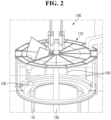
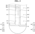
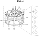
FIGS. 2 to 5 are views illustrating a configuration ofFIG. 1 in detail; and -
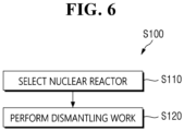
FIG. 6 is a flowchart sequentially illustrating an operation method of the nuclear power plant dismantling apparatus according to an embodiment of the present disclosure. - Hereinafter, embodiments of the present disclosure will be described in detail with reference to the accompanying drawings. Advantages and features of the present disclosure and methods for accomplishing these advantages and features will become apparent from embodiments to be described later in detail with reference to the accompanying drawings. However, the present disclosure is not limited to embodiments to be disclosed below, but may be implemented in various different forms, these embodiments will be provided only in order to make the present disclosure complete and allow one of ordinary skill in the art to completely recognize the scope of the present disclosure, and the present disclosure will be defined by the scope of the claims. Throughout the specification, the same components will be denoted by the same reference numerals.
- Referring to
FIG. 1 , a nuclear powerplant dismantling apparatus 100 according to an embodiment of the present disclosure includes aframe unit 110, acutting module 120, alink fixing module 130, apurging module 140, a fire extinguishingmodule 150, a gasconcentration analysis module 160, and asuction module 170. - Here, the
frame unit 110 includes anupper structure portion 111 and alower structure portion 112. Thelink fixing module 130 includescompartments compartments first compartment 131, asecond compartment 132, and athird compartment 133. - The
purging module 140 includes afirst purging module 141, asecond purging module 142, and athird purging module 143. The fire extinguishingmodule 150 includes an outercylindrical body 151 and an innercylindrical body 152. - Referring to
FIGS. 2 to 5 , theframe unit 110 is used to shield thenuclear reactor 10 to prevent contaminants in thenuclear reactor 10 from being released to the outside. To this end, theframe unit 110 is provided as a structure seated on an upper circumferential portion of thenuclear reactor 10 and having a predetermined shape. - The
cutting module 120 is provided on theframe unit 110 and performs cutting work on thenuclear reactor 10. Thelink fixing module 130 has a hollow area S1 formed therein. - The
link fixing module 130 enters an internal area M1 of thenuclear reactor 10 to link theframe unit 110 and thenuclear reactor 10 with each other. Here, the link may include various portions such as a physical connection and a functional operation. - The
purging module 140 enters the hollow area S1 of thelink fixing module 130. Thepurging module 140 enters the hollow area S1, and then performs purging on the inside of thenuclear reactor 10 in order to secure safety in the cutting work. - The
compartments link fixing module 130 into a plurality of portions in a height direction. Here, thefirst compartment 131 of thecompartments link fixing module 130, and forms a first area S11 for communication with the internal area M1. - In addition, the
second compartment 132 of thecompartments link fixing module 130, and forms a second area S12 for communication with the internal area M1 with thefirst compartment 131. - The
third compartment 133 of thecompartments link fixing module 130, and forms a third area S3 for communication with the internal area M1 with thesecond compartment 132. - Meanwhile, the
purging module 140 performs purging on the internal area M1 of thenuclear reactor 10 via the first area S11 to the third area S3. Thefirst purging module 141 of thepurging module 140 enters the third area S3 and supplies a first purging gas. - The
second purging module 142 of thepurging module 140 enters the second area S12 via thethird compartment 133 and supplies a second purging gas to the second area S12. - The
third purging module 143 of thepurging module 140 enters the first area S11 via thethird compartment 133 and thesecond compartment 132 and supplies a third purging gas to the first area S11. - Here, the
purging module 140 controls a purging level of the internal area M1 of thenuclear reactor 10 based on selective jetting of the first to third purging gases. - In the
purging module 140, the first to third purging gases may be the same as each other or at least one of the first to third purging gases may be different from the others of the first to third purging gases. - Meanwhile, at least one of the first to third purging gases includes an inert gas (e.g., nitrogen, argon, etc.). Meanwhile, the
link fixing module 130 has a plurality of through holes TH formed in a peripheral surface surrounding the first area S11 to thethird area S 13. - The
purging module 140 performs the purging on the internal area M1 of thenuclear reactor 10 by jetting the first to third purging gases based on the through holes TH. - The first purging gas of the
first purging module 141 enters a first internal area M11 corresponding to the first area S11 in the internal area M1 to purge thenuclear reactor 10. - In addition, the second purging gas of the
second purging module 142 enters a second internal area M12 corresponding to the second area S12 in the internal area M1 to purge thenuclear reactor 10. - The third purging gas of the
third purging module 143 enters a third internal area M13 corresponding to the third area S3 in the internal area M1 to purge thenuclear reactor 10. - Meanwhile, the
upper structure portion 111 of theframe unit 110 is provided in a predetermined shape. Thelower structure portion 112 of theframe unit 110 is provided to face theupper structure portion 111. - Each of the
upper structure portion 111 and thelower structure portion 112 is provided to have a cross-sectional shape such as a quadrangular shape, a polygonal shape, a circular shape, or an elliptical shape. In addition, asingle cutting module 120 or a plurality of cuttingmodules 120 are provided on theframe unit 110 and perform cutting work on thenuclear reactor 10. - A plurality of
fire extinguishing modules 150 are provided between theupper structure portion 111 and thelower structure portion 112. Thefire extinguishing module 150 serves to supply the fire extinguishing fluid L to a fire occurrence side where the fire occurs in response to the heat source. - The
fire extinguishing module 150 is provided on theframe unit 110, and when the fire occurs in thenuclear reactor 10, thefire extinguishing module 150 is melted by a heat source based on the fire to allow the fire extinguishing fluid L positioned therein is automatically supplied to the outside. - Meanwhile, the
lower structure portion 112 of theframe unit 110 described above is provided as a ring-shaped body surrounding a peripheral portion of thenuclear reactor 10. The plurality offire extinguishing module 150 are disposed on a peripheral portion of thelower structure portion 112. - The
fire extinguishing modules 150 each supply the fire extinguishing fluid L to the fire occurrence side based on the heat source. In addition, the outercylindrical body 151 of thefire extinguishing module 150 includes a hollow metal material. The innercylindrical body 152 of thefire extinguishing module 150 is accommodated inside the tubular portion. - The inner
cylindrical body 152 is filled with the fire extinguishing fluid L. The outercylindrical body 151 has a cut portion formed by cutting at least a portion of a peripheral portion of an outer peripheral surface thereof in a horizontal direction or a vertical direction. - At least a portion of the inner
cylindrical body 152 is melted in response to the fire. Through such melting, the fire extinguishing fluid L is supplied to the outside of the outercylindrical body 151 through the cut portion. - The gas
concentration analysis module 160 is provided at at least one position of theframe unit 110 and thenuclear reactor 10 or provided at a portion where theframe unit 110 and thenuclear reactor 10 are adjacent to each other and meet. - Through such a gas
concentration analysis module 160, the necessity for purging by thepurging module 140 may be grasped and the purging may be performed. In addition, it is possible to manage an operation of the purging module by continuously grasping whether or not the purging has been properly performed. - The
suction module 170 corresponds to thepurging module 140 and sucks the gas discharged through thepurging module 140. To this end, thesuction module 170 is provided on theframe unit 110 and thenuclear reactor 10. - In addition, the
suction module 170 may move between theframe unit 110 and thenuclear reactor 10, and may perform a suction operation. For example, thesuction module 170 may be provided to be movable up and down in a similar manner to thepurging module 140. - Referring to
FIG. 6 , in an operation method of the nuclear power plant dismantling apparatus according to an embodiment of the present disclosure, anuclear reactor 10 to be dismantled is selected. Nuclear power plant dismantling work is performed on thenuclear reactor 10 through the nuclearreactor dismantling apparatus 100. - Here, the nuclear
reactor dismantling apparatus 100 is provided with theframe unit 110 shielding thenuclear reactor 10 to prevent contaminants in thenuclear reactor 10 from being released to the outside. Such a nuclearreactor dismantling apparatus 100 includes a function for lifting the nuclear reactor. - The
cutting module 120 is provided on theframe unit 110 and performs cutting work on thenuclear reactor 10. Thelink fixing module 130 having a bar shape enters the internal space M1 of thenuclear reactor 10 to link theframe unit 110 and thenuclear reactor 10 with each other. - Such a
link fixing module 130 has the hollow area S1 formed therein. Meanwhile, thepurging module 140 enters the hollow area S1 of thelink fixing module 130, and performs purging on the inside of thenuclear reactor 10 in order to secure safety in the cutting work. - Meanwhile, the
fire extinguishing module 150 is provided on theframe unit 110. When a fire occurs in thenuclear reactor 10, thefire extinguishing module 150 is melted by a heat source based on the fire. Through such melting, the fire extinguishing fluid L positioned in thefire extinguishing module 150 is automatically supplied to the outside. - The embodiments of the present disclosure have been described hereinabove with reference to the accompanying drawings, but it will be understood by one of ordinary skill in the art to which the present disclosure pertains that various modifications and alterations may be made without departing from the technical spirit or essential feature of the present disclosure. Therefore, it is to be understood that the embodiments described above are illustrative rather than being restrictive in all aspects.
Claims (5)
- A nuclear power plant dismantling method comprising:selecting a nuclear reactor to be dismantled; andperforming nuclear power plant dismantling work on the nuclear reactor through a nuclear reactor dismantling apparatus,wherein the nuclear reactor dismantling apparatus includes:a frame unit shielding the nuclear reactor to prevent contaminants in the nuclear reactor from being released to the outside;a cutting module provided on the frame unit and performing cutting work on the nuclear reactor;a fire extinguishing module provided on the frame unit, and melted by a heat source based on a fire to automatically supply a fire extinguishing fluid positioned therein to the outside when the fire occurs in the nuclear reactor.
- The nuclear power plant dismantling method of claim 1, wherein the frame unit includes an upper structure portion and a lower structure portion facing the upper structure portion, and
a plurality of fire extinguishing modules are provided between the upper structure portion and the lower structure portion, and supply the fire extinguishing fluid to a fire occurrence side where the fire occurs in response to the heat source. - The nuclear power plant dismantling method of claim 2, wherein the lower structure portion of the frame unit is provided as a ring-shaped body surrounding a peripheral portion of the nuclear reactor, and
the plurality of fire extinguishing modules are disposed on a peripheral portion of the lower structure portion, and each supply the fire extinguishing fluid to the fire occurrence side based on the heat source. - The nuclear power plant dismantling method of claim 2, wherein the fire extinguishing module includes:an outer cylindrical body including a hollow metal material; andan inner cylindrical body accommodated inside the tubular portion and filled with the fire extinguishing fluid,the outer cylindrical body has a cut portion formed by cutting at least a portion of a peripheral portion of an outer peripheral surface thereof in a horizontal direction or a vertical direction, andwhen the inner cylindrical body is melted in response to the fire, the fire extinguishing fluid is supplied to the outside through the cut portion.
- A nuclear power plant dismantling apparatus comprising:a frame unit shielding the nuclear reactor to prevent contaminants in the nuclear reactor from being released to the outside;a cutting module provided on the frame unit and performing cutting work on the nuclear reactor; anda fire extinguishing module provided on the frame unit, and melted by a heat source based on a fire to automatically supply a fire extinguishing fluid positioned therein to the outside when the fire occurs in the nuclear reactor.
Applications Claiming Priority (2)
| Application Number | Priority Date | Filing Date | Title |
|---|---|---|---|
| KR1020220000749A KR102694502B1 (en) | 2022-01-04 | 2022-01-04 | Nuclear power plant dismantling method and apparatus |
| PCT/KR2023/000027 WO2023132582A1 (en) | 2022-01-04 | 2023-01-02 | Method and apparatus for dismantling nuclear power plant |
Publications (2)
| Publication Number | Publication Date |
|---|---|
| EP4462447A1 true EP4462447A1 (en) | 2024-11-13 |
| EP4462447A4 EP4462447A4 (en) | 2025-12-31 |
Family
ID=87073840
Family Applications (1)
| Application Number | Title | Priority Date | Filing Date |
|---|---|---|---|
| EP23737330.3A Pending EP4462447A4 (en) | 2022-01-04 | 2023-01-02 | METHOD AND DEVICE FOR DISMANTLING A NUCLEAR POWER PLANT |
Country Status (5)
| Country | Link |
|---|---|
| US (1) | US20250357016A1 (en) |
| EP (1) | EP4462447A4 (en) |
| JP (1) | JP7706024B2 (en) |
| KR (1) | KR102694502B1 (en) |
| WO (1) | WO2023132582A1 (en) |
Families Citing this family (1)
| Publication number | Priority date | Publication date | Assignee | Title |
|---|---|---|---|---|
| KR102926413B1 (en) * | 2025-10-02 | 2026-02-10 | 두산에너빌리티 주식회사 | Dismantling apparatus of nuclear reactor and dismantling method of nuclear reactor using the same |
Family Cites Families (15)
| Publication number | Priority date | Publication date | Assignee | Title |
|---|---|---|---|---|
| JPS569486Y2 (en) * | 1977-01-24 | 1981-03-03 | ||
| JP2000206294A (en) * | 1999-01-14 | 2000-07-28 | Hitachi Ltd | How to carry out large equipment |
| JP2011174897A (en) * | 2010-02-25 | 2011-09-08 | Mitsubishi Heavy Ind Ltd | Molten material cooling structure, reactor containment vessel provided with cooling structure, and nuclear power plant provided with containment vessel |
| KR101162486B1 (en) | 2010-08-27 | 2012-07-05 | 주식회사 우진 | Apparatus for treating of the In-Core Instrument assembly and the method thereof |
| KR101438108B1 (en) * | 2011-12-16 | 2014-09-12 | 두산중공업 주식회사 | Anti-seismic reinforcement assembly |
| US9881705B2 (en) * | 2012-03-16 | 2018-01-30 | Catherine Lin-Hendel | Emergency and back-up cooling of nuclear fuel and reactors and fire-extinguishing, explosion prevention using liquid nitrogen |
| KR101610483B1 (en) * | 2014-07-30 | 2016-04-20 | 두산중공업 주식회사 | Treatment device and method for waste steam generator, and installation method of treatment device for waste steam generator |
| KR101644274B1 (en) * | 2015-09-11 | 2016-07-29 | 한국수력원자력 주식회사 | Emergency hydrant supply apparatus for nuclear power plant |
| WO2018012503A1 (en) * | 2016-07-12 | 2018-01-18 | 三井化学産資株式会社 | Automatic fire extinguishing device |
| US11037426B2 (en) * | 2017-03-07 | 2021-06-15 | Ge-Hitachi Nuclear Energy Americas Llc | Systems and methods for combined lighting and radiation detection |
| KR102041966B1 (en) * | 2018-05-14 | 2019-11-07 | 한국원자력연구원 | Remote disassembly system for nuclear power plant and nuclear power plant having the same |
| KR102152410B1 (en) * | 2019-03-14 | 2020-09-04 | 한국수력원자력 주식회사 | Safety cover structure for decommissioning nuclear facilities |
| KR102101855B1 (en) * | 2019-06-18 | 2020-04-20 | 주식회사 남해이엔지 | Connection safety apparatus of distribution line |
| JP6876164B1 (en) * | 2020-01-27 | 2021-05-26 | 東芝プラントシステム株式会社 | Reactor pressure vessel dismantling device and reactor pressure vessel dismantling method |
| KR102449257B1 (en) * | 2020-06-11 | 2022-09-28 | 한국수력원자력 주식회사 | Fire suppression system for each fire zone of a nuclear power plant |
-
2022
- 2022-01-04 KR KR1020220000749A patent/KR102694502B1/en active Active
-
2023
- 2023-01-02 EP EP23737330.3A patent/EP4462447A4/en active Pending
- 2023-01-02 WO PCT/KR2023/000027 patent/WO2023132582A1/en not_active Ceased
- 2023-01-02 JP JP2024537081A patent/JP7706024B2/en active Active
- 2023-01-02 US US18/721,007 patent/US20250357016A1/en active Pending
Also Published As
| Publication number | Publication date |
|---|---|
| KR20230105409A (en) | 2023-07-11 |
| JP7706024B2 (en) | 2025-07-10 |
| KR102694502B1 (en) | 2024-08-09 |
| US20250357016A1 (en) | 2025-11-20 |
| EP4462447A4 (en) | 2025-12-31 |
| JP2024547068A (en) | 2024-12-26 |
| WO2023132582A1 (en) | 2023-07-13 |
Similar Documents
| Publication | Publication Date | Title |
|---|---|---|
| US20250357016A1 (en) | Method and apparatus for dismantling nuclear power plant | |
| JP3119090B2 (en) | Underwater laser processing device and underwater construction method using the device | |
| CN100345659C (en) | Thermal cutting machine and cutting method using the same | |
| RU2727372C1 (en) | Protection system for laser cutting machine | |
| KR101754538B1 (en) | Method for dismantling Reactor Vessel Internal and Reactor Vessel | |
| KR102185335B1 (en) | Aparatus and method for dismantling for heavy water reactor facilities | |
| KR102599814B1 (en) | Automatic fire extinguishing apparatus for fires caused by disassembling of waste batteries | |
| JPH029556B2 (en) | ||
| RU2751389C1 (en) | Protective system for a laser cutting machine | |
| EP4462446A1 (en) | Method and apparatus for decommissioning nuclear power plant | |
| CN105014235A (en) | Laser processing system | |
| JP2019138916A (en) | Reactor building whole cover device, and reactor building preparation working method | |
| US8859930B2 (en) | Thermal cutting machine | |
| US20050150721A1 (en) | Working device for inner wall surface of tower tank, and inner wall surface working method using the same | |
| KR102120934B1 (en) | Aparatus and method for dismantling for heavy water reactor facilities | |
| JP2016217987A (en) | Method for opening reactor pressure vessel and method for removing fuel debris | |
| JP6360458B2 (en) | How to retrieve fuel debris | |
| JP4167198B2 (en) | Reactor body disassembly method | |
| EP1993104B1 (en) | Method for dismantling heat exchanger installed in building for nuclear reactor | |
| JP3861142B2 (en) | Reactor pressure vessel cutting method and pitch hold jig used in the cutting method | |
| JP2002243884A (en) | Adding method for hatch of reactor containment | |
| JP3757077B2 (en) | Water jet peening method and apparatus | |
| CN120698198A (en) | A battery pack flip device abnormality processing method, system and device | |
| CN217142673U (en) | Numerical control flame plasma cutting machine | |
| CN217749741U (en) | Punching machine |
Legal Events
| Date | Code | Title | Description |
|---|---|---|---|
| STAA | Information on the status of an ep patent application or granted ep patent |
Free format text: STATUS: THE INTERNATIONAL PUBLICATION HAS BEEN MADE |
|
| PUAI | Public reference made under article 153(3) epc to a published international application that has entered the european phase |
Free format text: ORIGINAL CODE: 0009012 |
|
| STAA | Information on the status of an ep patent application or granted ep patent |
Free format text: STATUS: REQUEST FOR EXAMINATION WAS MADE |
|
| 17P | Request for examination filed |
Effective date: 20240619 |
|
| AK | Designated contracting states |
Kind code of ref document: A1 Designated state(s): AL AT BE BG CH CY CZ DE DK EE ES FI FR GB GR HR HU IE IS IT LI LT LU LV MC ME MK MT NL NO PL PT RO RS SE SI SK SM TR |
|
| DAV | Request for validation of the european patent (deleted) | ||
| DAX | Request for extension of the european patent (deleted) | ||
| A4 | Supplementary search report drawn up and despatched |
Effective date: 20251201 |
|
| RIC1 | Information provided on ipc code assigned before grant |
Ipc: G21D 1/00 20060101AFI20251125BHEP Ipc: A62C 35/10 20060101ALI20251125BHEP Ipc: G21C 9/04 20060101ALN20251125BHEP |