EP4462153A2 - Pose graph slam computation method and system based on 4d millimeter-wave radar - Google Patents
Pose graph slam computation method and system based on 4d millimeter-wave radar Download PDFInfo
- Publication number
- EP4462153A2 EP4462153A2 EP24174589.2A EP24174589A EP4462153A2 EP 4462153 A2 EP4462153 A2 EP 4462153A2 EP 24174589 A EP24174589 A EP 24174589A EP 4462153 A2 EP4462153 A2 EP 4462153A2
- Authority
- EP
- European Patent Office
- Prior art keywords
- point cloud
- radar
- point
- velocity
- pose
- Prior art date
- Legal status (The legal status is an assumption and is not a legal conclusion. Google has not performed a legal analysis and makes no representation as to the accuracy of the status listed.)
- Pending
Links
Images

Classifications
-
- G—PHYSICS
- G06—COMPUTING OR CALCULATING; COUNTING
- G06T—IMAGE DATA PROCESSING OR GENERATION, IN GENERAL
- G06T7/00—Image analysis
- G06T7/70—Determining position or orientation of objects or cameras
- G06T7/73—Determining position or orientation of objects or cameras using feature-based methods
-
- G—PHYSICS
- G01—MEASURING; TESTING
- G01S—RADIO DIRECTION-FINDING; RADIO NAVIGATION; DETERMINING DISTANCE OR VELOCITY BY USE OF RADIO WAVES; LOCATING OR PRESENCE-DETECTING BY USE OF THE REFLECTION OR RERADIATION OF RADIO WAVES; ANALOGOUS ARRANGEMENTS USING OTHER WAVES
- G01S13/00—Systems using the reflection or reradiation of radio waves, e.g. radar systems; Analogous systems using reflection or reradiation of waves whose nature or wavelength is irrelevant or unspecified
- G01S13/88—Radar or analogous systems specially adapted for specific applications
- G01S13/93—Radar or analogous systems specially adapted for specific applications for anti-collision purposes
- G01S13/931—Radar or analogous systems specially adapted for specific applications for anti-collision purposes of land vehicles
-
- G—PHYSICS
- G01—MEASURING; TESTING
- G01S—RADIO DIRECTION-FINDING; RADIO NAVIGATION; DETERMINING DISTANCE OR VELOCITY BY USE OF RADIO WAVES; LOCATING OR PRESENCE-DETECTING BY USE OF THE REFLECTION OR RERADIATION OF RADIO WAVES; ANALOGOUS ARRANGEMENTS USING OTHER WAVES
- G01S13/00—Systems using the reflection or reradiation of radio waves, e.g. radar systems; Analogous systems using reflection or reradiation of waves whose nature or wavelength is irrelevant or unspecified
- G01S13/02—Systems using reflection of radio waves, e.g. primary radar systems; Analogous systems
- G01S13/50—Systems of measurement based on relative movement of target
- G01S13/58—Velocity or trajectory determination systems; Sense-of-movement determination systems
-
- G—PHYSICS
- G01—MEASURING; TESTING
- G01S—RADIO DIRECTION-FINDING; RADIO NAVIGATION; DETERMINING DISTANCE OR VELOCITY BY USE OF RADIO WAVES; LOCATING OR PRESENCE-DETECTING BY USE OF THE REFLECTION OR RERADIATION OF RADIO WAVES; ANALOGOUS ARRANGEMENTS USING OTHER WAVES
- G01S13/00—Systems using the reflection or reradiation of radio waves, e.g. radar systems; Analogous systems using reflection or reradiation of waves whose nature or wavelength is irrelevant or unspecified
- G01S13/02—Systems using reflection of radio waves, e.g. primary radar systems; Analogous systems
- G01S13/06—Systems determining position data of a target
- G01S13/42—Simultaneous measurement of distance and other co-ordinates
-
- G—PHYSICS
- G01—MEASURING; TESTING
- G01S—RADIO DIRECTION-FINDING; RADIO NAVIGATION; DETERMINING DISTANCE OR VELOCITY BY USE OF RADIO WAVES; LOCATING OR PRESENCE-DETECTING BY USE OF THE REFLECTION OR RERADIATION OF RADIO WAVES; ANALOGOUS ARRANGEMENTS USING OTHER WAVES
- G01S13/00—Systems using the reflection or reradiation of radio waves, e.g. radar systems; Analogous systems using reflection or reradiation of waves whose nature or wavelength is irrelevant or unspecified
- G01S13/02—Systems using reflection of radio waves, e.g. primary radar systems; Analogous systems
- G01S13/50—Systems of measurement based on relative movement of target
- G01S13/52—Discriminating between fixed and moving objects or between objects moving at different speeds
-
- G—PHYSICS
- G01—MEASURING; TESTING
- G01S—RADIO DIRECTION-FINDING; RADIO NAVIGATION; DETERMINING DISTANCE OR VELOCITY BY USE OF RADIO WAVES; LOCATING OR PRESENCE-DETECTING BY USE OF THE REFLECTION OR RERADIATION OF RADIO WAVES; ANALOGOUS ARRANGEMENTS USING OTHER WAVES
- G01S13/00—Systems using the reflection or reradiation of radio waves, e.g. radar systems; Analogous systems using reflection or reradiation of waves whose nature or wavelength is irrelevant or unspecified
- G01S13/02—Systems using reflection of radio waves, e.g. primary radar systems; Analogous systems
- G01S13/50—Systems of measurement based on relative movement of target
- G01S13/58—Velocity or trajectory determination systems; Sense-of-movement determination systems
- G01S13/581—Velocity or trajectory determination systems; Sense-of-movement determination systems using transmission of interrupted pulse modulated waves and based upon the Doppler effect resulting from movement of targets
- G01S13/582—Velocity or trajectory determination systems; Sense-of-movement determination systems using transmission of interrupted pulse modulated waves and based upon the Doppler effect resulting from movement of targets adapted for simultaneous range and velocity measurements
-
- G—PHYSICS
- G01—MEASURING; TESTING
- G01S—RADIO DIRECTION-FINDING; RADIO NAVIGATION; DETERMINING DISTANCE OR VELOCITY BY USE OF RADIO WAVES; LOCATING OR PRESENCE-DETECTING BY USE OF THE REFLECTION OR RERADIATION OF RADIO WAVES; ANALOGOUS ARRANGEMENTS USING OTHER WAVES
- G01S13/00—Systems using the reflection or reradiation of radio waves, e.g. radar systems; Analogous systems using reflection or reradiation of waves whose nature or wavelength is irrelevant or unspecified
- G01S13/02—Systems using reflection of radio waves, e.g. primary radar systems; Analogous systems
- G01S13/50—Systems of measurement based on relative movement of target
- G01S13/58—Velocity or trajectory determination systems; Sense-of-movement determination systems
- G01S13/583—Velocity or trajectory determination systems; Sense-of-movement determination systems using transmission of continuous unmodulated waves, amplitude-, frequency-, or phase-modulated waves and based upon the Doppler effect resulting from movement of targets
- G01S13/584—Velocity or trajectory determination systems; Sense-of-movement determination systems using transmission of continuous unmodulated waves, amplitude-, frequency-, or phase-modulated waves and based upon the Doppler effect resulting from movement of targets adapted for simultaneous range and velocity measurements
-
- G—PHYSICS
- G01—MEASURING; TESTING
- G01S—RADIO DIRECTION-FINDING; RADIO NAVIGATION; DETERMINING DISTANCE OR VELOCITY BY USE OF RADIO WAVES; LOCATING OR PRESENCE-DETECTING BY USE OF THE REFLECTION OR RERADIATION OF RADIO WAVES; ANALOGOUS ARRANGEMENTS USING OTHER WAVES
- G01S13/00—Systems using the reflection or reradiation of radio waves, e.g. radar systems; Analogous systems using reflection or reradiation of waves whose nature or wavelength is irrelevant or unspecified
- G01S13/02—Systems using reflection of radio waves, e.g. primary radar systems; Analogous systems
- G01S13/50—Systems of measurement based on relative movement of target
- G01S13/58—Velocity or trajectory determination systems; Sense-of-movement determination systems
- G01S13/60—Velocity or trajectory determination systems; Sense-of-movement determination systems wherein the transmitter and receiver are mounted on the moving object, e.g. for determining ground speed, drift angle, ground track
-
- G—PHYSICS
- G01—MEASURING; TESTING
- G01S—RADIO DIRECTION-FINDING; RADIO NAVIGATION; DETERMINING DISTANCE OR VELOCITY BY USE OF RADIO WAVES; LOCATING OR PRESENCE-DETECTING BY USE OF THE REFLECTION OR RERADIATION OF RADIO WAVES; ANALOGOUS ARRANGEMENTS USING OTHER WAVES
- G01S13/00—Systems using the reflection or reradiation of radio waves, e.g. radar systems; Analogous systems using reflection or reradiation of waves whose nature or wavelength is irrelevant or unspecified
- G01S13/88—Radar or analogous systems specially adapted for specific applications
- G01S13/89—Radar or analogous systems specially adapted for specific applications for mapping or imaging
-
- G—PHYSICS
- G01—MEASURING; TESTING
- G01S—RADIO DIRECTION-FINDING; RADIO NAVIGATION; DETERMINING DISTANCE OR VELOCITY BY USE OF RADIO WAVES; LOCATING OR PRESENCE-DETECTING BY USE OF THE REFLECTION OR RERADIATION OF RADIO WAVES; ANALOGOUS ARRANGEMENTS USING OTHER WAVES
- G01S7/00—Details of systems according to groups G01S13/00, G01S15/00, G01S17/00
- G01S7/02—Details of systems according to groups G01S13/00, G01S15/00, G01S17/00 of systems according to group G01S13/00
- G01S7/41—Details of systems according to groups G01S13/00, G01S15/00, G01S17/00 of systems according to group G01S13/00 using analysis of echo signal for target characterisation; Target signature; Target cross-section
- G01S7/411—Identification of targets based on measurements of radar reflectivity
- G01S7/412—Identification of targets based on measurements of radar reflectivity based on a comparison between measured values and known or stored values
-
- G—PHYSICS
- G01—MEASURING; TESTING
- G01S—RADIO DIRECTION-FINDING; RADIO NAVIGATION; DETERMINING DISTANCE OR VELOCITY BY USE OF RADIO WAVES; LOCATING OR PRESENCE-DETECTING BY USE OF THE REFLECTION OR RERADIATION OF RADIO WAVES; ANALOGOUS ARRANGEMENTS USING OTHER WAVES
- G01S7/00—Details of systems according to groups G01S13/00, G01S15/00, G01S17/00
- G01S7/02—Details of systems according to groups G01S13/00, G01S15/00, G01S17/00 of systems according to group G01S13/00
- G01S7/41—Details of systems according to groups G01S13/00, G01S15/00, G01S17/00 of systems according to group G01S13/00 using analysis of echo signal for target characterisation; Target signature; Target cross-section
- G01S7/414—Discriminating targets with respect to background clutter
-
- G—PHYSICS
- G01—MEASURING; TESTING
- G01S—RADIO DIRECTION-FINDING; RADIO NAVIGATION; DETERMINING DISTANCE OR VELOCITY BY USE OF RADIO WAVES; LOCATING OR PRESENCE-DETECTING BY USE OF THE REFLECTION OR RERADIATION OF RADIO WAVES; ANALOGOUS ARRANGEMENTS USING OTHER WAVES
- G01S7/00—Details of systems according to groups G01S13/00, G01S15/00, G01S17/00
- G01S7/02—Details of systems according to groups G01S13/00, G01S15/00, G01S17/00 of systems according to group G01S13/00
- G01S7/41—Details of systems according to groups G01S13/00, G01S15/00, G01S17/00 of systems according to group G01S13/00 using analysis of echo signal for target characterisation; Target signature; Target cross-section
- G01S7/415—Identification of targets based on measurements of movement associated with the target
-
- G—PHYSICS
- G06—COMPUTING OR CALCULATING; COUNTING
- G06T—IMAGE DATA PROCESSING OR GENERATION, IN GENERAL
- G06T7/00—Image analysis
- G06T7/30—Determination of transform parameters for the alignment of images, i.e. image registration
- G06T7/33—Determination of transform parameters for the alignment of images, i.e. image registration using feature-based methods
- G06T7/337—Determination of transform parameters for the alignment of images, i.e. image registration using feature-based methods involving reference images or patches
-
- G—PHYSICS
- G06—COMPUTING OR CALCULATING; COUNTING
- G06T—IMAGE DATA PROCESSING OR GENERATION, IN GENERAL
- G06T2207/00—Indexing scheme for image analysis or image enhancement
- G06T2207/10—Image acquisition modality
- G06T2207/10028—Range image; Depth image; 3D point clouds
-
- G—PHYSICS
- G06—COMPUTING OR CALCULATING; COUNTING
- G06T—IMAGE DATA PROCESSING OR GENERATION, IN GENERAL
- G06T2207/00—Indexing scheme for image analysis or image enhancement
- G06T2207/10—Image acquisition modality
- G06T2207/10032—Satellite or aerial image; Remote sensing
- G06T2207/10044—Radar image
-
- Y—GENERAL TAGGING OF NEW TECHNOLOGICAL DEVELOPMENTS; GENERAL TAGGING OF CROSS-SECTIONAL TECHNOLOGIES SPANNING OVER SEVERAL SECTIONS OF THE IPC; TECHNICAL SUBJECTS COVERED BY FORMER USPC CROSS-REFERENCE ART COLLECTIONS [XRACs] AND DIGESTS
- Y02—TECHNOLOGIES OR APPLICATIONS FOR MITIGATION OR ADAPTATION AGAINST CLIMATE CHANGE
- Y02T—CLIMATE CHANGE MITIGATION TECHNOLOGIES RELATED TO TRANSPORTATION
- Y02T10/00—Road transport of goods or passengers
- Y02T10/10—Internal combustion engine [ICE] based vehicles
- Y02T10/40—Engine management systems
Definitions
- the present invention relates to the field of robot technologies, and specifically to a pose graph SLAM computation method and system based on a 4D millimeter-wave radar.
- Millimeter-wave radars have been widely used in the synchronous localization and mapping (SLAM) technology, especially in the field of autonomous driving. Compared with optical sensors such as a camera or lidar, the millimeter-wave radar is less sensitive to weather and light conditions and is much cheaper. However, despite these advantages, the millimeter-wave radar usually has a sparser point cloud and larger noise compared to the lidar, which poses challenges for precise localization and mapping. In recent years, the latest millimeter-wave radar sensor, namely 4D imaging radar (4D radar), has received increasing attention in autonomous driving due to its unique advantages over conventional radars.
- 4D imaging radar 4D radar
- the scanning radar performs a 360-degree scan on the surrounding environment, and provides a two-dimensional radar energy image without velocity information.
- the automotive radar usually has a smaller field of view and provides a sparse 2D point cloud with a Doppler velocity.
- the 4D radar has a longer detection distance and a larger field of view.
- a 4D point cloud provided by the 4D radar has information in four dimensions: distance, azimuth angle, elevation angle, and Doppler velocity.
- the 4D radar also provides some low-level features, such as an energy intensity or a radar scattering cross section. Because the 4D radar has additional information and higher resolution, it provides new opportunities for the application of SLAM.
- millimeter-wave radar SLAM SLAM
- researchers at home and abroad have done a lot of research.
- the millimeter-wave radars may be roughly divided into two types.
- SLAM algorithms based on the scanning radar, which occupy a dominant position in millimeter-wave radar SLAM.
- This type of algorithms uses 2D images obtained by the scanning radar as an input, and usually uses some feature extraction algorithms to extract feature points from the images, and then performs scanning registration based on the feature points.
- the most famous of the algorithms is the RadarSLAM algorithm proposed by Hong et al. [1] ( Z. Hong, Y. Petillot, and S. Wang, "RadarSLAM: Radar based Large-Scale SLAM in All Weathers," in 2020 IEEE/RSJ International Conference on Intelligent Robots and Systems (IROS), Oct. 2020, pp. 5164-5170, iSSN: 2153-086 ).
- the other type is the SLAM algorithm based on the automotive radar.
- This type of algorithm uses a sparse radar point cloud obtained by a conventional automotive radar as an input, and uses Doppler velocity information in the point cloud or scanning registration of the point cloud to estimate ego vehicle motion.
- Kellner et al. [2] D. Kellner, M. Barjenbruch, J. Klappstein, J. Dickmann, and K. Dietmayer, "Instantaneous ego-motion estimation using Doppler radar," in 16th International IEEE Conference on Intelligent Transportation Systems (ITSC 2013), Oct. 2013, pp.
- Kung et al. proposed a radar odometry algorithm suitable for scanning radars and automotive radars [3] ( P.-C. Kung, C.-C. Wang, and W.-C. Lin, "A Normal Distribution Transform-Based Radar Odometry Designed For Scanning and Automotive Radars," in 2021 IEEE International Conference on Robotics and Automation (ICRA). Xi'an, China: IEEE, May 2021, pp. 14 417-14 423 .). They use the ego vehicle velocity estimation method proposed by Kellner et al.
- the radar submap is only a simple superposition of consecutive radar point clouds using the ego vehicle velocity estimation, so its accuracy depends largely on the accuracy of the ego vehicle velocity estimation.
- Patent document CN111522043A discloses an unmanned vehicle lidar rapid rematching and positioning method, which relates to the field of unmanned driving.
- This present invention is divided into a multi-sensor calibration module, a pose fusion module, and a fusion positioning module.
- multi-sensor joint calibration consistency description of a target is obtained.
- Data fusion is performed on pose information of an unmanned vehicle resolved by a GPS sensor and a lidar sensor, to obtain vehicle pose information fused by the GPS sensor and the lidar sensor.
- an objective of the present invention is to provide a pose graph SLAM computation method and system based on a 4D millimeter-wave radar.
- the pose graph SLAM computation method based on a 4D millimeter-wave radar includes:
- step S1 the ground point cloud is extracted, and the two consecutive frames of point clouds are compared, to remove the ghost points below the ground and the unstable random points, so as to reduce noise in the 4D radar point cloud, where step S1 includes the following steps:
- step S2 the following steps are included:
- step S3 pose graph optimization is performed, where the pose graph is estimated and constructed using the relative pose transformation that is obtained through the point cloud registration, the velocity pre-integration, and the loop closure detection; and finally the optimal pose is estimated through the graph optimization, where the following steps are included:
- step S3.3 includes loop closure detection, where a position that has been previously reached is identified, in polar coordinates, the 4D radar point cloud is divided into grids, a 3D point cloud is mapped to a 2D matrix, a value of each element in the matrix is a maximum energy intensity of radar points in a corresponding grid, as the device moves, a cosine distance between a 2D matrix of the current frame and a 2D matrix generated by each of all previous keyframes is continuously searched for and computed, and if the distance is less than a set threshold, it is considered that a loop closure has been detected; when a loop closure is detected, a relative pose transformation between the current frame and a submap composed of a loop closure frame and nearby keyframes is computed; and an error of estimation of the pose transformation is e L ; and
- a pose graph SLAM computation system based on a 4D millimeter-wave radar provided according to the present invention includes:
- pose graph optimization is performed, where the pose graph is estimated and constructed using the relative pose transformation that is obtained through the point cloud registration, the velocity pre-integration, and the loop closure detection; and finally the optimal pose is estimated through the graph optimization, where
- a module M3.3 is configured to perform the following operation: loop closure detection, where a position that has been previously reached is identified, in polar coordinates, the 4D radar point cloud is divided into grids, a 3D point cloud is mapped to a 2D matrix, a value of each element in the matrix is a maximum energy intensity of radar points in a corresponding grid, as the device moves, a cosine distance between a 2D matrix of the current frame and a 2D matrix generated by each of all previous keyframes is continuously searched for and computed, and if the distance is less than a set threshold, it is considered that a loop closure has been detected; when a loop closure is detected, a relative pose transformation between the current frame and a submap composed of a loop closure frame and nearby keyframes is computed; and an error of estimation of the pose transformation is e L ; and
- the present invention has the following beneficial effects:
- FIG. 1 is a schematic flowchart of a method according to the present invention.
- the present invention innovatively proposes a pose graph SLAM algorithm based on a 4D millimeter-wave radar.
- This algorithm may be applied to manned intelligent wheelchairs, autonomous vehicles, and the like to implement accurate and robust synchronous positioning and mapping tasks.
- the present invention provides a pose graph SLAM algorithm based on a 4D millimeter-wave radar.
- the algorithm includes three modules: a radar point cloud filtering module, an ego vehicle velocity estimation module, and a pose graph optimization module.
- a filtering step is designed to reduce ghost points and random noise in the original 4D radar point cloud.
- an ego vehicle velocity is estimated from the Doppler velocity in the filtered point cloud, which plays an important role in subsequent pose graph optimization.
- radar odometry is implemented through point cloud registration based on a normal distribution transformation, to estimate a relative pose transformation.
- the estimated ego vehicle velocity is pre-integrated, to obtain an additional relative pose estimate.
- loop closure detection is introduced to identify places that have been reached again, and historical poses are optimized from a global perspective, to reduce a cumulative drift and implement accurate and robust mapping and localization.
- the pose graph SLAM computation method based on a 4D millimeter-wave radar provided according to the present invention includes: step S1: extracting a ground point cloud, and comparing two consecutive frames of point clouds, to remove ghost points below the ground and random points.
- step S1 Specifically, in step S1,
- Step S2 includes: estimating a linear velocity and an angular velocity of a device based on Doppler velocity information in a 4D radar point cloud.
- step S2 includes:
- Step S3 includes: estimating and constructing a pose graph using a relative pose transformation that is obtained through point cloud registration performed based on a normal distribution transformation, pre-integration performed using an estimated device velocity, and loop closure detection; and estimating an optimal pose through graph optimization.
- step S3 Specifically, in step S3,
- step S3.3 includes: loop closure detection, where a position that has been previously reached is identified, in polar coordinates, the 4D radar point cloud is divided into grids, a 3D point cloud is mapped to a 2D matrix, a value of each element in the matrix is a maximum energy intensity of radar points in a corresponding grid, as the device moves, a cosine distance between a 2D matrix of the current frame and a 2D matrix generated by each of all previous keyframes is continuously searched for and computed, and if the distance is less than a set threshold, it is considered that a loop closure has been detected; when a loop closure is detected, a relative pose transformation between the current frame and a submap composed of a loop closure frame and nearby keyframes is computed; and an error of estimation of the pose transformation is e L ; and
- Embodiment 2 is a preferred example of Embodiment 1 to illustrate the present invention more specifically.
- the present invention further provides a pose graph SLAM computation system based on a 4D millimeter-wave radar.
- the pose graph SLAM computation system based on a 4D millimeter-wave radar may be implemented by performing process steps of the pose graph SLAM computation method based on a 4D millimeter-wave radar, that is, those skilled in the art may understand the pose graph SLAM computation method based on a 4D millimeter-wave radar as a preferred implementation of the pose graph SLAM computation system based on a 4D millimeter-wave radar.
- the pose graph SLAM computation system based on a 4D millimeter-wave radar includes a module M1, a module M2, and a module M3.
- the module M1 is configured to extract a ground point cloud, and compare two consecutive frames of point clouds, to remove ghost points below the ground and random points.
- the module M2 is configured to estimate a linear velocity and an angular velocity of a device based on Doppler velocity information in a 4D radar point cloud.
- the module M3 is configured to estimate and construct a pose graph using a relative pose transformation that is obtained through point cloud registration performed based on a normal distribution transformation, pre-integration performed using an estimated device velocity, and loop closure detection; and estimate an optimal pose through graph optimization.
- a module M3.3 is configured to perform the following operation: loop closure detection, where a position that has been previously reached is identified, in polar coordinates, the 4D radar point cloud is divided into grids, a 3D point cloud is mapped to a 2D matrix, a value of each element in the matrix is a maximum energy intensity of radar points in a corresponding grid, as the device moves, a cosine distance between a 2D matrix of the current frame and a 2D matrix generated by each of all previous keyframes is continuously searched for and computed, and if the distance is less than a set threshold, it is considered that a loop closure has been detected; when a loop closure is detected, a relative pose transformation between the current frame and a submap composed of a loop closure frame and nearby keyframes is computed; and an error of estimation of the pose transformation is e L ; and
- Embodiment 3 is a preferred example of Embodiment 1 to illustrate the present invention more specifically.
- this specification innovatively proposes a pose graph SLAM algorithm based on a 4D millimeter-wave radar, which is suitable for the synchronous positioning and mapping issue of vehicles or mobile robots in an unknown environment.
- the pose graph SLAM algorithm based on a 4D millimeter-wave radar provided according to the present invention mainly includes the following steps:
- the radar point cloud filtering process in step 1 mainly includes the following steps.
- step 1.1 ghost point removal is performed, where ghost points are false measurements below the ground in the original 4D radar point cloud caused by the multipath effect of millimeter waves, and they are one of 4D radar measurement noises.
- the ground point cloud is extracted from the original radar point cloud and then the ghost points below the ground are filtered out.
- n a number of points in the point cloud
- r i , ⁇ i , ⁇ i are spatial information of the point measured by the 4D radar:a distance, an azimuth angle, and an elevation angle.
- a point with a distance less than a threshold ⁇ r and a height within a threshold ⁇ h near a mounting height H of the radar is first retained, that is, for all P i ⁇ , points that meet x i 2 + y i 2 + z i 2 ⁇ ⁇ r and z i ⁇ [-H - ⁇ h , -H + ⁇ h ] are retained, because these points are most likely to belong to the ground.
- an upward normal vector n i of each point is estimated using a principal component analysis method.
- a point with a normal vector having an angle less than ⁇ n with a z-axis positive unit vector is retained, that is, a point that meets n i ⁇ (0,0,1) T ⁇ cos ⁇ n is retained.
- step 1.2 random point removal is performed, where random points are unstable and flickering false measurements contained in the original 4D radar point cloud, and are one of the measurement noises of the 4D radar. Since random points do not appear continuously in a plurality of consecutive frames of radar point clouds, random points are identified and filtered out by comparing a current point cloud and a previous frame of point cloud adjacent to the current point cloud.
- P k ⁇ 1 ′ is obtained by transforming the previous frame of point cloud into the coordinate system of the current frame using R k-1 and t k-1 . If no point in P k ⁇ 1 ′ exists near a point in the current frame, the current point is classified as a random point and filtered out.
- the ego vehicle velocity estimation process in step 2 mainly includes the following steps.
- step 2.1 static point extraction is performed.
- the 4D radar can also obtain a Doppler velocity of each point in the point cloud. For an i th point in the 4D radar point cloud, if it is a stationary point with an absolute velocity of 0 in the real world, then its relative velocity to the radar is equal in magnitude and opposite in direction to the velocity of the radar.
- the Doppler velocity is a radial component of a relative velocity between the measured point and the 4D radar.
- v s R s T v ⁇ + ⁇ ⁇ ⁇ t s ,
- step 2.2 least squares estimation is performed, where after the static points are extracted, the ego vehicle velocity is estimated based on the relationships between the Doppler velocities of all the static points and the ego vehicle velocity again using the least square method.
- the pose graph optimization process in step 3 mainly includes the following steps.
- step 3.1 point cloud registration is performed based on the normal distribution transformation, where the relative transformation is estimated by direct matching between a current 4D radar point cloud and a keyframe submap.
- a sliding window method is used to establish a denser radar submap using a plurality of keyframe point clouds. Specifically, if a translation or rotation from a last keyframe to a current point cloud exceeds a threshold, a current frame is selected as a new keyframe. Then, the new keyframe is added to the radar submap, and a node associated with the keyframe is added to the pose graph. When a number of keyframes in the submap exceeds a size of the window, the earliest keyframe is discarded.
- the radar submap established through this method can reflect local environmental features more clearly than a single frame of radar point cloud, improving the accuracy and robustness of point cloud registration.
- the submap is evenly divided into grids of a same size, and a point cloud in each grid is modeled as a local normal distribution. Due to the highly sparse 4D radar point cloud, a case where there are less than three points in a grid or points in the grid are collinear (coplanar) may easily occur after grid division, making it difficult to invert the covariance of the normal distribution. Therefore, measurement uncertainty of each point is comprehensively considered when computing a mean and a covariance of the normal distribution. An advantage of this is to reduce the degeneration effect of covariance, and point cloud information in a grid can be fully used even when there are very few points in the grid.
- the current 4D radar point cloud is registered with the radar submap to estimate a relative pose transformation that maximizes a distribution probability of the current point cloud in the submap, and the relative pose transformation is added to the pose graph as a radar odometry factor.
- An error of estimation of the pose transformation is e O .
- step 3.2 velocity pre-integration is performed, where the relative pose transformation is computed using the estimated ego vehicle velocity, so that an additional reliable relative pose estimate is introduced, improving the accuracy and robustness of SLAM.
- step 3.3 loop closure detection is performed to identify places that have been previously reached, so as to reduce a cumulative drift.
- the 4D radar point cloud is divided into grids, a 3D point cloud is mapped to a 2D matrix, and a value of each element in the matrix is a maximum energy intensity of radar points in a corresponding grid.
- a cosine distance between a 2D matrix of the current frame and a 2D matrix generated by each of all previous keyframes is continuously searched for and computed, and if the distance is less than a set threshold, it is considered that a loop closure has been detected.
- a relative pose transformation between the current frame and a submap composed of a loop closure frame and nearby keyframes is computed using the registration method introduced in the point cloud registration step.
- An error of estimation of the pose transformation is e L .
- step 3.4 graph optimization is performed, where the pose graph is established, error terms of relative pose estimates at all moments are comprehensively considered, and optimal poses of the ego vehicle at all moments are estimated through graph optimization.
- the present invention is divided into three parts: (1) radar point cloud filtering, (2) ego vehicle velocity estimation, and (3) pose graph optimization, which mainly include the following steps.
- step 1 radar point cloud filtering is performed, where the original 4D radar point cloud mainly contains two types of noise: ghost points and random points, the ground point cloud is extracted, and the two consecutive frames of point clouds are compared, to remove the ghost points below the ground and the unstable random points, so as to reduce noise in the 4D radar point cloud.
- the original 4D radar point cloud mainly contains two types of noise: ghost points and random points
- the ground point cloud is extracted, and the two consecutive frames of point clouds are compared, to remove the ghost points below the ground and the unstable random points, so as to reduce noise in the 4D radar point cloud.
- step 1.1 ghost point removal is performed, where ghost points are false measurements below the ground in the original 4D radar point cloud caused by the multipath effect of millimeter waves, and they are one of the 4D radar measurement noises.
- the ground point cloud is extracted from the original radar point cloud and then the ghost points below the ground are filtered out.
- n a number of points in the point cloud
- r i , ⁇ i , ⁇ i are spatial information of the point measured by the 4D radar:a distance, an azimuth angle, and an elevation angle.
- a point with a distance less than a threshold ⁇ r and a height within a threshold ⁇ h near a mounting height H of the radar is first retained, that is, for all P i ⁇ , points that meet x i 2 + y i 2 + z i 2 ⁇ ⁇ r and z i ⁇ [-H - ⁇ h , -H + ⁇ h ] are retained, because these points are most likely to belong to the ground.
- an upward normal vector n i of each point is estimated using a principal component analysis method.
- a point with a normal vector having an angle less than ⁇ n with a z-axis positive unit vector is retained, that is, a point that meets n i ⁇ (0,0,1) T ⁇ cos ⁇ n is retained.
- step 1.2 random point removal is performed, where random points are unstable and flickering false measurements contained in the original 4D radar point cloud, and are one of the measurement noises of the 4D radar. Since random points do not appear continuously in a plurality of consecutive frames of radar point clouds, random points are identified and filtered out by comparing a current point cloud and a previous frame of point cloud adjacent to the current point cloud.
- the transformed previous frame of point cloud P k ⁇ 1 ′ is obtained by transforming the previous frame of point cloud into the coordinate system of the current frame using R k-1 and t k-1 .
- a KD tree is constructed using P k ⁇ 1 ′ , so as to implement nearest neighbor search. If no point in P k ⁇ 1 ′ exists within a specific range of a point in the current point cloud , the current point is classified as a random point and filtered out.
- step 2 ego vehicle velocity estimation is performed, where the 4D millimeter-wave radar can obtain a Doppler velocity of each point, and the Doppler velocity is a radial component of a relative velocity between the radar and a target point. Based on the property of the Doppler velocity, a linear velocity and an angular velocity of an ego vehicle are estimated based on Doppler velocity information in a 4D radar point cloud.
- step 2.1 static point extraction is performed.
- the 4D radar can also obtain a Doppler velocity of each point in the point cloud. For an i th point in the 4D radar point cloud, if it is a stationary point with an absolute velocity of 0 in the real world, then its relative velocity to the radar is equal in magnitude and opposite in direction to the velocity of the radar.
- the Doppler velocity is a radial component of a relative velocity between the measured point and the 4D radar.
- v s R s T v ⁇ + ⁇ ⁇ ⁇ t s ,
- step 2.2 least squares estimation is performed, where after the static points are extracted, the ego vehicle velocity is estimated based on the relationships between the Doppler velocities of all the static points and the ego vehicle velocity again and the least square method.
- step 3 pose graph optimization is performed, where a current radar point cloud is registered with a local radar keyframe submap based on a normal distribution transformation, so as to obtain a millimeter-wave radar odometry factor; pre-integration is performed using the estimated ego vehicle velocity, so as to obtain a velocity pre-integration factor; and loop closure detection is performed to obtain a loop closure factor.
- the three factors are used to construct a pose graph, and an optimal pose is estimated based on graph optimization.
- step 3.1 point cloud registration is performed based on the normal distribution transformation, where the relative transformation is estimated by direct matching between a current 4D radar point cloud and a keyframe submap.
- a sliding window method is used to establish a denser radar submap using a plurality of keyframe point clouds. Specifically, if a translation or rotation from a last keyframe to a current point cloud exceeds a threshold, a current frame is selected as a new keyframe. Then, the new keyframe is added to the radar submap, and a node associated with the keyframe is added to the pose graph. When a number of keyframes in the submap exceeds a size of the window, the earliest keyframe is discarded.
- the radar submap established through this method can reflect local environmental features more clearly than a single frame of radar point cloud, improving the accuracy and robustness of point cloud registration.
- the submap is evenly divided into grids of a same size, and a point cloud in each grid is modeled as a local normal distribution. Due to the sparsity of the 4D radar point cloud, a case where there are less than three points in a grid or points in the grid are collinear (coplanar) may easily occur after grid division, making it difficult to invert the covariance of the normal distribution. Therefore, measurement uncertainty of each point is comprehensively considered when computing a mean and a covariance of the normal distribution. An advantage of this is to reduce the degeneration effect of covariance, and point cloud information in a grid can be fully used even when there are very few points in the grid.
- the current 4D radar point cloud is registered with the radar submap to estimate a relative pose transformation x ⁇ ij O that maximizes a distribution probability of the current point cloud in the submap, and the relative pose transformation is added to the pose graph as a radar odometry factor between nodes corresponding to moments i and j.
- e O ⁇ i j ⁇ K ⁇ Log x ⁇ ij O ⁇ 1 x i ⁇ 1 x j ⁇ ⁇ ij O 2 , where ⁇ ij O is a corresponding covariance matrix, Log(-) : SE(3) ⁇ R 6 is a logarithmic mapping (SE(3) is a three-dimensional special Euclidean group, and R 6 is a six-dimensional real number vector space) of a three-dimensional transformation.
- step 3.2 velocity pre-integration is performed, where the relative pose transformation is computed using the estimated ego vehicle velocity, so that an additional reliable relative pose estimate is introduced, improving the accuracy and robustness of SLAM.
- a position p t+ ⁇ t and a rotation R t+ ⁇ t at a moment t + ⁇ t can be computed based on a position p t and a rotation R t at a moment t:
- ⁇ R ik R i T R k , J r ,k is a right Jacobian matrix of ⁇ k ⁇ t , v ⁇ k ⁇ is an antisymmetric matrix of a vector ⁇ k , ⁇ R ⁇ ij and ⁇ p ⁇ ij are respectively a relative rotation and a relative translation obtained by ego vehicle velocity pre-integration, and are added to the pose graph as a velocity pre-integration factor between nodes corresponding to moments i and j.
- ⁇ ij is a linear combination of a zero-mean Gaussian noise ⁇ k ⁇
- ⁇ ij is a zero-mean Gaussian noise.
- ⁇ p ij is a zero-mean Gaussian noise because it is a linear combination of zero-mean Gaussian noises ⁇ ik and ⁇ k v .
- step 3.3 loop closure detection is performed to identify places that have been previously reached, so as to reduce a cumulative drift.
- the 4D radar point cloud is divided into grids, a 3D point cloud is mapped to a 2D matrix, and a value of each element in the matrix is a maximum energy intensity of radar points in a corresponding grid.
- a cosine distance between a 2D matrix of the current frame and a 2D matrix generated by each of all previous keyframes is continuously searched for and computed, and if the distance is less than a set threshold, it is considered that a loop closure has been detected.
- a relative pose transformation x ⁇ kj L between the current frame j and a submap composed of a loop closure frame k and nearby keyframes is computed using the registration method introduced in the point cloud registration step. Then, x ⁇ kj L is added to the pose graph as a loop closure factor between nodes corresponding to moments j and k.
- step 3.4 graph optimization is performed, where the pose graph is established, error terms of all relative pose estimates are comprehensively considered, and optimal poses of the ego vehicle at all moments are estimated through graph optimization, implementing more accurate and robust localization and mapping.
- All nodes in the pose graph correspond to poses at different moments, and edges between the nodes correspond to relative pose transformations between different moments.
- X ⁇ x i ⁇ , i ⁇
- the system and the apparatus as well as various modules thereof provided by the present invention can certainly be implemented in the form of logic gates, switches, application-specific integrated circuits, programmable logic controllers, and embedded microcontrollers by logically programming the method steps to implement the same program. Therefore, the system and the apparatus as well as various modules thereof provided by the present invention may be considered as a hardware component, and the modules included therein for implementing various programs may also be considered as structures within the hardware component. The modules for implementing various functions may also be considered as both software programs for implementing methods and structures within the hardware component.
Landscapes
- Engineering & Computer Science (AREA)
- Remote Sensing (AREA)
- Radar, Positioning & Navigation (AREA)
- Physics & Mathematics (AREA)
- General Physics & Mathematics (AREA)
- Computer Networks & Wireless Communication (AREA)
- Electromagnetism (AREA)
- Computer Vision & Pattern Recognition (AREA)
- Theoretical Computer Science (AREA)
- Radar Systems Or Details Thereof (AREA)
Abstract
Description
- The present invention relates to the field of robot technologies, and specifically to a pose graph SLAM computation method and system based on a 4D millimeter-wave radar.
- Millimeter-wave radars have been widely used in the synchronous localization and mapping (SLAM) technology, especially in the field of autonomous driving. Compared with optical sensors such as a camera or lidar, the millimeter-wave radar is less sensitive to weather and light conditions and is much cheaper. However, despite these advantages, the millimeter-wave radar usually has a sparser point cloud and larger noise compared to the lidar, which poses challenges for precise localization and mapping. In recent years, the latest millimeter-wave radar sensor, namely 4D imaging radar (4D radar), has received increasing attention in autonomous driving due to its unique advantages over conventional radars.
- Conventional millimeter-wave radars may be divided into two types: scanning radars and automotive radars. The scanning radar performs a 360-degree scan on the surrounding environment, and provides a two-dimensional radar energy image without velocity information. In addition, the automotive radar usually has a smaller field of view and provides a sparse 2D point cloud with a Doppler velocity. Compared with conventional millimeter-wave radar sensors, the 4D radar has a longer detection distance and a larger field of view. A 4D point cloud provided by the 4D radar has information in four dimensions: distance, azimuth angle, elevation angle, and Doppler velocity. In addition, the 4D radar also provides some low-level features, such as an energy intensity or a radar scattering cross section. Because the 4D radar has additional information and higher resolution, it provides new opportunities for the application of SLAM.
- Regarding the issue of millimeter-wave radar SLAM, researchers at home and abroad have done a lot of research. According to the types of millimeter-wave radars applied, the millimeter-wave radars may be roughly divided into two types.
- One type is SLAM algorithms based on the scanning radar, which occupy a dominant position in millimeter-wave radar SLAM. This type of algorithms uses 2D images obtained by the scanning radar as an input, and usually uses some feature extraction algorithms to extract feature points from the images, and then performs scanning registration based on the feature points. The most famous of the algorithms is the RadarSLAM algorithm proposed by Hong et al. [1] (Z. Hong, Y. Petillot, and S. Wang, "RadarSLAM: Radar based Large-Scale SLAM in All Weathers," in 2020 IEEE/RSJ International Conference on Intelligent Robots and Systems (IROS), Oct. 2020, pp. 5164-5170, iSSN: 2153-086). Inspired by visual SLAM related methods, they extract SURF feature points from radar images and perform registration. In addition, there are also some methods implementing scanning radar SLAM using deep learning. However, these methods are not applicable to 4D radar point clouds because they use 2D scanning radar images as an input.
- The other type is the SLAM algorithm based on the automotive radar. This type of algorithm uses a sparse radar point cloud obtained by a conventional automotive radar as an input, and uses Doppler velocity information in the point cloud or scanning registration of the point cloud to estimate ego vehicle motion. Kellner et al. [2] (D. Kellner, M. Barjenbruch, J. Klappstein, J. Dickmann, and K. Dietmayer, "Instantaneous ego-motion estimation using Doppler radar," in 16th International IEEE Conference on Intelligent Transportation Systems (ITSC 2013), Oct. 2013, pp. 869-874, iSSN: 2153-0017.) uses the Doppler velocity information in the radar point cloud to compute an ego vehicle velocity, thereby implementing ego vehicle motion estimation. Kung et al. proposed a radar odometry algorithm suitable for scanning radars and automotive radars [3] (P.-C. Kung, C.-C. Wang, and W.-C. Lin, "A Normal Distribution Transform-Based Radar Odometry Designed For Scanning and Automotive Radars," in 2021 IEEE International Conference on Robotics and Automation (ICRA). Xi'an, China: IEEE, May 2021, pp. 14 417-14 423.). They use the ego vehicle velocity estimation method proposed by Kellner et al. to merge a plurality of frames of radar point clouds into a radar submap. Then, scanning matching based on a normal distribution transformation is applied to perform matching between two radar submaps, implementing ego vehicle motion estimation. However, the radar submap is only a simple superposition of consecutive radar point clouds using the ego vehicle velocity estimation, so its accuracy depends largely on the accuracy of the ego vehicle velocity estimation.
- Patent document
CN111522043A discloses an unmanned vehicle lidar rapid rematching and positioning method, which relates to the field of unmanned driving. This present invention is divided into a multi-sensor calibration module, a pose fusion module, and a fusion positioning module. Through multi-sensor joint calibration, consistency description of a target is obtained. Data fusion is performed on pose information of an unmanned vehicle resolved by a GPS sensor and a lidar sensor, to obtain vehicle pose information fused by the GPS sensor and the lidar sensor. When point cloud matching of a lidar SLAM positioning module fails, a fused pose is used for replacing a positioning prediction matrix of a point cloud matching algorithm, rapid rematching of the lidar SLAM algorithm is implemented, and continuous positioning of the unmanned vehicle SLAM algorithm is implemented. However, this present invention does not introduce loop closure detection to identify places that have been reached again, and therefore cannot optimize historical poses from a global perspective. - In view of the deficiencies in the prior art, an objective of the present invention is to provide a pose graph SLAM computation method and system based on a 4D millimeter-wave radar.
- The pose graph SLAM computation method based on a 4D millimeter-wave radar provided according to the present invention includes:
- step S1: extracting a ground point cloud, and comparing two consecutive frames of point clouds, to remove ghost points below the ground and random points;
- step S2: estimating a linear velocity and an angular velocity of a device based on Doppler velocity information in a 4D radar point cloud; and
- step S3: estimating and constructing a pose graph using a relative pose transformation that is obtained through point cloud registration performed based on a normal distribution transformation, pre-integration performed using an estimated device velocity, and loop closure detection; and estimating an optimal pose through graph optimization.
- Preferably, in step S1,
the ground point cloud is extracted, and the two consecutive frames of point clouds are compared, to remove the ghost points below the ground and the unstable random points, so as to reduce noise in the 4D radar point cloud, where step S1 includes the following steps: - step S1.1: ghost point removal, where the ground point cloud is extracted from an original radar point cloud and the ghost points below the ground are filtered out;
- for the original radar point cloud = {P i }, i ∈ { 1, 2, ..., n } measured by a 4D radar, n is a number of points in the point cloud;

- a position of each point in a radar coordinate system is expressed as P i = (xi, yi, zi ) T = (ri cos θ i cos ϕ i , ri sin θ i cos ϕ i , r i sin (ϕi) T , where ri is a distance of the point measured by the 4D radar, θi is an azimuth angle of the point measured by the 4D radar, and ϕi is an elevation angle of the point measured by the 4D radar; and
- for the original radar point cloud, a point with a distance less than a threshold δr and a height within a threshold δh near a mounting height of the radar is retained, an upward normal vector of each point is computed using a principal component analysis method, a point with a normal vector having an angle less than δn with a z-axis positive unit vector is retained, ground points are extracted using a random sample consensus algorithm, and the ghost points below the ground are filtered out; and
- step S1.2: random point removal, where the random points are identified and filtered out by comparing a current point cloud and a previous frame of point cloud adjacent to the current point cloud, for the current point cloud and the previous frame of point cloud adjacent to the current point cloud, a pose transformation between the current point cloud and the previous frame of point cloud is computed based on the device velocity, the previous frame of point cloud is transformed into a coordinate system of the current frame, and if the transformed previous frame of point cloud does not exist within a preset range near a point in the current frame, the point is classified as a random point and filtered out; and
- a rotation transformation Rk-1 and a translation transformation tk-1 between the current point cloud and the previous frame of point cloud
 adjacent to the current point cloud are computed:


- where ṽ k-1 and ω̃ k-1 are respectively a device linear velocity estimate and a device angular velocity estimate of the previous frame, Δt is a time difference between the two frames, Exp(·):R3 → SO(3) is an exponential mapping of a three-dimensional rotation, R3 is a three-dimensional real number vector space, SO(3) is a three-dimensional special orthogonal group , and


- Preferably, in step S2, the following steps are included:
- step S2.1: static point extraction, where for an ith point in the 4D radar point cloud, a relationship between a Doppler velocity of the point and a velocity of the radar is as follows:

- where vr,i is the Doppler velocity of the ith point, d i = (cos θ i cos ϕi, sin θ i cos ϕi, sin ϕi ) T is a unit direction vector of the point relative to the radar, and vs is the velocity of the radar; and
- a relationship between the velocity of the radar and the device velocity is as follows:

- where ts and Rs are respectively a mounting position and a pose of the 4D radar in a device coordinate system, ṽ ∈ R 3 and ω̃ ∈ R 3 are respectively the linear velocity and the angular velocity of the device, and for all static points in the 4D radar point cloud, the Doppler velocity and the device velocity both conform to the following equation:
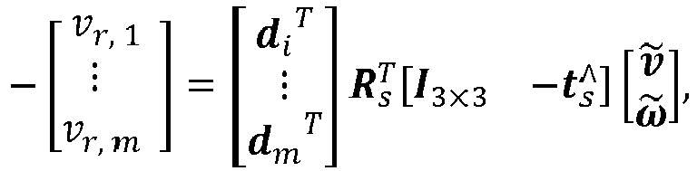
- where m is a number of all the static points in the point cloud, I3×3 is a 3 × 3 unit matrix,

- step S2.2: least squares estimation, where after the static points are extracted, the device velocity is computed based on the relationships between the Doppler velocities of all the static points and the device velocity using the least square method.
- Preferably, in step S3,
pose graph optimization is performed, where the pose graph is estimated and constructed using the relative pose transformation that is obtained through the point cloud registration, the velocity pre-integration, and the loop closure detection; and finally the optimal pose is estimated through the graph optimization, where the following steps are included: - step S3.1: point cloud registration based on the normal distribution transformation, where a relative transformation is estimated by matching between a current 4D radar point cloud and a keyframe submap;
- a radar submap is established using a plurality of keyframe point clouds and a sliding window, if a translation or rotation from a last keyframe to a current point cloud exceeds a threshold, a current frame is selected as a new keyframe, the new keyframe is added to the radar submap, and when a number of keyframes in the submap exceeds a size of the window, the earliest keyframe is discarded; and
- after the radar submap is established, the submap is evenly divided into grids of a same size, a point cloud in each grid is modeled as a local normal distribution, measurement uncertainty of each point is considered when computing a mean and a covariance of the normal distribution, and the current 4D radar point cloud is registered with the radar submap to compute a relative pose transformation that maximizes a distribution probability of the current point cloud in the submap, where an error of estimation of the pose transformation is eO; and
- step SQ.: velocity pre-integration, where the relative pose transformation is computed based on the estimated device velocity, so that an additional reliable relative pose estimate is introduced, and a device linear velocity and a device angular velocity that are estimated at a moment t are respectively denoted as ṽ t and ω̃ t, with their estimated values being true values each plus a zero-mean Gaussian white noise:


- where ωt and Wvt are respectively the true values of the angular velocity and the linear velocity in a world coordinate system,


- Preferably, step S3.3 includes loop closure detection, where a position that has been previously reached is identified, in polar coordinates, the 4D radar point cloud is divided into grids, a 3D point cloud is mapped to a 2D matrix, a value of each element in the matrix is a maximum energy intensity of radar points in a corresponding grid, as the device moves, a cosine distance between a 2D matrix of the current frame and a 2D matrix generated by each of all previous keyframes is continuously searched for and computed, and if the distance is less than a set threshold, it is considered that a loop closure has been detected; when a loop closure is detected, a relative pose transformation between the current frame and a submap composed of a loop closure frame and nearby keyframes is computed; and an error of estimation of the pose transformation is eL; and
- step S3.4 includes graph optimization, where the pose graph is established, error terms of relative pose estimates at all moments are considered, optimal poses of the device at all moments are estimated through graph optimization, all nodes in the pose graph correspond to poses at different moments, and edges between the nodes correspond to relative pose transformations between different moments; and all the poses are expressed as X = { x i }, i ∈ , and the optimal pose .X'* is estimated by solving a nonlinear least squares problem:


- where includes all moments, and eO, eV, eL respectively correspond to the errors of relative pose transformations obtained in different steps.

- A pose graph SLAM computation system based on a 4D millimeter-wave radar provided according to the present invention includes:
- a module M1 configured to extract a ground point cloud, and compare two consecutive frames of point clouds, to remove ghost points below the ground and random points;
- a module M2 configured to estimate a linear velocity and an angular velocity of a device based on Doppler velocity information in a 4D radar point cloud; and
- a module M3 configured to estimate and construct a pose graph using a relative pose transformation that is obtained through point cloud registration performed based on a normal distribution transformation, pre-integration performed using an estimated device velocity, and loop closure detection; and estimate an optimal pose through graph optimization.
- Preferably, in the module M1,
- the ground point cloud is extracted, and the two consecutive frames of point clouds are compared, to remove the ghost points below the ground and the unstable random points, so as to reduce noise in the 4D radar point cloud, where
- a module M1.1 is configured to perform the following operation: ghost point removal, where the ground point cloud is extracted from an original radar point cloud and the ghost points below the ground are filtered out;
- for the original radar point cloud = {P i }, i ∈ { 1, 2, ..., n} measured by a 4D radar, n is a number of points in the point cloud;

- a position of each point in a radar coordinate system is expressed as P i = (xi, yi, zi ) T = (r i cos θ i cos ϕ i , r i sin θ i cos ϕ i , r i sin ϕ i ) T , where ri is a distance of the point measured by the 4D radar, θi; is an azimuth angle of the point measured by the 4D radar, and ϕi is an elevation angle of the point measured by the 4D radar; and
- for the original radar point cloud, a point with a distance less than a threshold δr and a height within a threshold δh near a mounting height of the radar is retained, an upward normal vector of each point is computed using a principal component analysis method, a point with a normal vector having an angle less than δn with a z-axis positive unit vector is retained, ground points are extracted using a random sample consensus algorithm, and the ghost points below the ground are filtered out; and
- a module M1.2 is configured to perform the following operation: random point removal, where the random points are identified and filtered out by comparing a current point cloud and a previous frame of point cloud adjacent to the current point cloud, for the current point cloud and the previous frame of point cloud adjacent to the current point cloud, a pose transformation between the current point cloud and the previous frame of point cloud is computed based on the device velocity, the previous frame of point cloud is transformed into a coordinate system of the current frame, and if the transformed previous frame of point cloud does not exist within a preset range near a point in the current frame, the point is classified as a random point and filtered out; and
- a rotation transformation Rk-1 and a translation transformation tk-1 between the current point cloud and the previous frame of point cloud
 adjacent to the current point cloud are computed:


- where ṽ k-1 and ω̃ k-1 are respectively a device linear velocity estimate and a device angular velocity estimate of the previous frame, Δt is a time difference between the two frames, Exp(·): R3 → SO(3) is an exponential mapping of a three-dimensional rotation, R3 is a three-dimensional real number vector space, SO(3) is a three-dimensional special orthogonal group , and


- Preferably, in the module M2,
- a module M2.1 is configured to perform the following operation: static point extraction, where for an ith point in the 4D radar point cloud, a relationship between a Doppler velocity of the point and a velocity of the radar is as follows:

- where vr,i is the Doppler velocity of the ith point, d i = (cos θ i cos ϕi, sin θ i cos ϕi, sin ϕi ) T is a unit direction vector of the point relative to the radar, and vs is the velocity of the radar; and
- a relationship between the velocity of the radar and the device velocity is as follows:

- where ts and Rs are respectively a mounting position and a pose of the 4D radar in a device coordinate system, ṽ ∈ R 3 and ω̃ ∈ R 3 are respectively the linear velocity and the angular velocity of the device, and for all static points in the 4D radar point cloud, the Doppler velocity and the device velocity both conform to the following equation:

- where m is a number of all the static points in the point cloud, I3×3 is a 3 × 3 unit matrix,

- a module M2.2 is configured to perform the following operation: least squares estimation, where after the static points are extracted, the device velocity is computed based on the relationships between the Doppler velocities of all the static points and the device velocity using the least square method.
- Preferably, in the module M3,
pose graph optimization is performed, where the pose graph is estimated and constructed using the relative pose transformation that is obtained through the point cloud registration, the velocity pre-integration, and the loop closure detection; and finally the optimal pose is estimated through the graph optimization, where - a module M3.1 is configured to perform the following operation: point cloud registration based on the normal distribution transformation, where a relative transformation is estimated by matching between a current 4D radar point cloud and a keyframe submap;
- a radar submap is established using a plurality of keyframe point clouds and a sliding window, if a translation or rotation from a last keyframe to a current point cloud exceeds a threshold, a current frame is selected as a new keyframe, the new keyframe is added to the radar submap, and when a number of keyframes in the submap exceeds a size of the window, the earliest keyframe is discarded; and
- after the radar submap is established, the submap is evenly divided into grids of a same size, a point cloud in each grid is modeled as a local normal distribution, measurement uncertainty of each point is considered when computing a mean and a covariance of the normal distribution, and the current 4D radar point cloud is registered with the radar submap to compute a relative pose transformation that maximizes a distribution probability of the current point cloud in the submap, where an error of estimation of the pose transformation is eO; and
- a module M3.2 is configured to perform the following operation: velocity pre-integration, where the relative pose transformation is computed based on the estimated device velocity, so that an additional reliable relative pose estimate is introduced, and a device linear velocity and a device angular velocity that are estimated at a moment t are respectively denoted as ṽ t and ω̃ t , with their estimated values being true values each plus a zero-mean Gaussian white noise:


- where ωt and WVt are respectively the true values of the angular velocity and the linear velocity in a world coordinate system,


- Preferably, a module M3.3 is configured to perform the following operation: loop closure detection, where a position that has been previously reached is identified, in polar coordinates, the 4D radar point cloud is divided into grids, a 3D point cloud is mapped to a 2D matrix, a value of each element in the matrix is a maximum energy intensity of radar points in a corresponding grid, as the device moves, a cosine distance between a 2D matrix of the current frame and a 2D matrix generated by each of all previous keyframes is continuously searched for and computed, and if the distance is less than a set threshold, it is considered that a loop closure has been detected; when a loop closure is detected, a relative pose transformation between the current frame and a submap composed of a loop closure frame and nearby keyframes is computed; and an error of estimation of the pose transformation is eL; and
- a module M3.4 is configured to perform the following operation: graph optimization, where the pose graph is established, error terms of relative pose estimates at all moments are considered, optimal poses of the device at all moments are estimated through graph optimization, all nodes in the pose graph correspond to poses at different moments, and edges between the nodes correspond to relative pose transformations between different moments; and all the poses are expressed as X = { x i }, i ∈ , and the optimal pose X * is estimated by solving a nonlinear least squares problem:


- where includes all moments, and eO, eV, eL respectively correspond to the errors of relative pose transformations obtained in different steps.

- Compared with the prior art, the present invention has the following beneficial effects:
- 1. In order to achieve better accuracy in the case of the sparse point cloud, the present invention pre-integrates the estimated ego vehicle velocity, to obtain the additional relative pose estimate.
- 2. The present invention introduces the loop closure detection to identify places that have been reached again, thereby optimizing historical poses from a global perspective, to reduce a cumulative drift and implement accurate and robust mapping and localization.
- 3. The present invention can use the 4D millimeter-wave radar to perform accurate and robust synchronous positioning and mapping in an unknown environment.
- Other features, objectives, and advantages of the present invention will become more apparent by reading the detailed description of non-limiting embodiments with reference to the following accompanying drawing, in which:
FIG. 1 is a schematic flowchart of a method according to the present invention. - The present invention is described in detail in combination with specific embodiments as below. The following embodiments will help those skilled in the art to further understand the present invention, but do not limit the present invention in any way. It should be noted that a person of ordinary skill in the art may also make several changes and improvements without departing from the concept of the present invention. These all belong to the scope of protection of the present invention.
- In view of the previous work, the present invention innovatively proposes a pose graph SLAM algorithm based on a 4D millimeter-wave radar. This algorithm may be applied to manned intelligent wheelchairs, autonomous vehicles, and the like to implement accurate and robust synchronous positioning and mapping tasks.
- The present invention provides a pose graph SLAM algorithm based on a 4D millimeter-wave radar. The algorithm includes three modules: a radar point cloud filtering module, an ego vehicle velocity estimation module, and a pose graph optimization module. Aiming at the problem of large noise in a 4D millimeter-wave radar (4D radar) point cloud, a filtering step is designed to reduce ghost points and random noise in the original 4D radar point cloud. Next, an ego vehicle velocity is estimated from the Doppler velocity in the filtered point cloud, which plays an important role in subsequent pose graph optimization. In the pose graph optimization, radar odometry is implemented through point cloud registration based on a normal distribution transformation, to estimate a relative pose transformation. In order to achieve better accuracy in the case of a sparse point cloud, the estimated ego vehicle velocity is pre-integrated, to obtain an additional relative pose estimate. In addition, loop closure detection is introduced to identify places that have been reached again, and historical poses are optimized from a global perspective, to reduce a cumulative drift and implement accurate and robust mapping and localization.
- The pose graph SLAM computation method based on a 4D millimeter-wave radar provided according to the present invention, as shown in
FIG. 1 , includes:
step S1: extracting a ground point cloud, and comparing two consecutive frames of point clouds, to remove ghost points below the ground and random points. - Specifically, in step S1,
- the ground point cloud is extracted, and the two consecutive frames of point clouds are compared, to remove the ghost points below the ground and the unstable random points, so as to reduce noise in the 4D radar point cloud, where step S1 includes the following steps:
- step S1.1: ghost point removal, where the ground point cloud is extracted from an original radar point cloud and the ghost points below the ground are filtered out;
- for the original radar point cloud = {P i }, i ∈ { 1, 2, ..., n } measured by a 4D radar, n is a number of points in the point cloud;

- a position of each point in a radar coordinate system is expressed as P i = (xi, yi, zi ) T = (r i cos θ i cos ϕ i , r i sin θ i cos ϕ i , ri sin ϕ i ) T , where ri is a distance of the point measured by the 4D radar, θi is an azimuth angle of the point measured by the 4D radar, and ϕi is an elevation angle of the point measured by the 4D radar; and
- for the original radar point cloud, a point with a distance less than a threshold δr and a height within a threshold δh near a mounting height of the radar is retained, an upward normal vector of each point is computed using a principal component analysis method, a point with a normal vector having an angle less than δn with a z-axis positive unit vector is retained, ground points are extracted using a random sample consensus algorithm, and the ghost points below the ground are filtered out; and
- step S1.2: random point removal, where the random points are identified and filtered out by comparing a current point cloud and a previous frame of point cloud adjacent to the current point cloud, for the current point cloud and the previous frame of point cloud adjacent to the current point cloud, a pose transformation between the current point cloud and the previous frame of point cloud is computed based on the device velocity, the previous frame of point cloud is transformed into a coordinate system of the current frame, and if the transformed previous frame of point cloud does not exist within a preset range near a point in the current frame, the point is classified as a random point and filtered out; and
- a rotation transformation Rk-1 and a translation transformation tk-1 between the current point cloud and the previous frame of point cloud
 adjacent to the current point cloud are computed:


- where ṽ k-1 and ω̃ k-1 are respectively a device linear velocity estimate and a device angular velocity estimate of the previous frame, Δt is a time difference between the two frames, Exp(·): R3 → SO(3) is an exponential mapping of a three-dimensional rotation, R3 is a three-dimensional real number vector space, SO(3) is a three-dimensional special orthogonal group , and


- Step S2 includes: estimating a linear velocity and an angular velocity of a device based on Doppler velocity information in a 4D radar point cloud.
- Specifically, step S2 includes:
- step S2.1: static point extraction, where for an ith point in the 4D radar point cloud, a relationship between a Doppler velocity of the point and a velocity of the radar is as follows:

- where vr,i is the Doppler velocity of the ith point, d i = (cos θi cos ϕi, sin θi cos ϕi, sin ϕi ) T is a unit direction vector of the point relative to the radar, and vs is the velocity of the radar; and
- a relationship between the velocity of the radar and the device velocity is as follows:

- where ts and Rs are respectively a mounting position and a pose of the 4D radar in a device coordinate system, ṽ ∈ R 3 and ω̃ ∈ R 3 are respectively the linear velocity and the angular velocity of the device, and for all static points in the 4D radar point cloud, the Doppler velocity and the device velocity both conform to the following equation:

- where m is a number of all the static points in the point cloud, I3×3 is a 3 × 3 unit matrix,

- step S2.2: least squares estimation, where after the static points are extracted, the device velocity is computed based on the relationships between the Doppler velocities of all the static points and the device velocity using the least square method.
- Step S3 includes: estimating and constructing a pose graph using a relative pose transformation that is obtained through point cloud registration performed based on a normal distribution transformation, pre-integration performed using an estimated device velocity, and loop closure detection; and estimating an optimal pose through graph optimization.
- Specifically, in step S3,
- pose graph optimization is performed, where the pose graph is estimated and constructed using the relative pose transformation that is obtained through the point cloud registration, the velocity pre-integration, and the loop closure detection; and finally the optimal pose is estimated through the graph optimization, where the following steps are included:
- step S3.1: point cloud registration based on the normal distribution transformation, where a relative transformation is estimated by matching between a current 4D radar point cloud and a keyframe submap;
- a radar submap is established using a plurality of keyframe point clouds and a sliding window, if a translation or rotation from a last keyframe to a current point cloud exceeds a threshold, a current frame is selected as a new keyframe, the new keyframe is added to the radar submap, and when a number of keyframes in the submap exceeds a size of the window, the earliest keyframe is discarded; and
- after the radar submap is established, the submap is evenly divided into grids of a same size, a point cloud in each grid is modeled as a local normal distribution, measurement uncertainty of each point is considered when computing a mean and a covariance of the normal distribution, and the current 4D radar point cloud is registered with the radar submap to compute a relative pose transformation that maximizes a distribution probability of the current point cloud in the submap, where an error of estimation of the pose transformation is eO; and
- step S3.2: velocity pre-integration, where the relative pose transformation is computed based on the estimated device velocity, so that an additional reliable relative pose estimate is introduced, and a device linear velocity and a device angular velocity that are estimated at a moment t are respectively denoted as ṽ t and ω̃ t , with their estimated values being true values each plus a zero-mean Gaussian white noise:


- where ωt and WV t are respectively the true values of the angular velocity and the linear velocity in a world coordinate system,


- Specifically, step S3.3 includes: loop closure detection, where a position that has been previously reached is identified, in polar coordinates, the 4D radar point cloud is divided into grids, a 3D point cloud is mapped to a 2D matrix, a value of each element in the matrix is a maximum energy intensity of radar points in a corresponding grid, as the device moves, a cosine distance between a 2D matrix of the current frame and a 2D matrix generated by each of all previous keyframes is continuously searched for and computed, and if the distance is less than a set threshold, it is considered that a loop closure has been detected; when a loop closure is detected, a relative pose transformation between the current frame and a submap composed of a loop closure frame and nearby keyframes is computed; and an error of estimation of the pose transformation is eL; and
- step S3.4 includes: graph optimization, where the pose graph is established, error terms of relative pose estimates at all moments are considered, optimal poses of the device at all moments are estimated through graph optimization, all nodes in the pose graph correspond to poses at different moments, and edges between the nodes correspond to relative pose transformations between different moments; and all the poses are expressed as X = { x i }, i ∈ , and the optimal pose .X'* is estimated by solving a nonlinear least squares problem:


- where includes all moments, and eO, eV, eL respectively correspond to the errors of relative pose transformations obtained in different steps.

- Embodiment 2 is a preferred example of Embodiment 1 to illustrate the present invention more specifically.
- The present invention further provides a pose graph SLAM computation system based on a 4D millimeter-wave radar. The pose graph SLAM computation system based on a 4D millimeter-wave radar may be implemented by performing process steps of the pose graph SLAM computation method based on a 4D millimeter-wave radar, that is, those skilled in the art may understand the pose graph SLAM computation method based on a 4D millimeter-wave radar as a preferred implementation of the pose graph SLAM computation system based on a 4D millimeter-wave radar.
- The pose graph SLAM computation system based on a 4D millimeter-wave radar provided according to the present invention includes a module M1, a module M2, and a module M3.
- The module M1 is configured to extract a ground point cloud, and compare two consecutive frames of point clouds, to remove ghost points below the ground and random points.
- Specifically, in the module M1,
- the ground point cloud is extracted, and the two consecutive frames of point clouds are compared, to remove the ghost points below the ground and the unstable random points, so as to reduce noise in the 4D radar point cloud, where
- a module M1.1 is configured to perform the following operation: ghost point removal, where the ground point cloud is extracted from an original radar point cloud and the ghost points below the ground are filtered out;
- for the original radar point cloud = {P i }, i ∈ { 1, 2, ..., n } measured by a 4D radar, n is a number of points in the point cloud;

- a position of each point in a radar coordinate system is expressed as P i = (xi, yi, zi ) T = (r i cos θ i cos ϕ i , ri sin θ i cos ϕ i , ri sin ϕ i ) T , where ri is a distance of the point measured by the 4D radar, θi is an azimuth angle of the point measured by the 4D radar, and ϕi is an elevation angle of the point measured by the 4D radar; and
- for the original radar point cloud, a point with a distance less than a threshold δr and a height within a threshold δh near a mounting height of the radar is retained, an upward normal vector of each point is computed using a principal component analysis method, a point with a normal vector having an angle less than δn with a z-axis positive unit vector is retained, ground points are extracted using a random sample consensus algorithm, and the ghost points below the ground are filtered out; and
- a module M1.2 is configured to perform the following operation: random point removal, where the random points are identified and filtered out by comparing a current point cloud and a previous frame of point cloud adjacent to the current point cloud, for the current point cloud and the previous frame of point cloud adjacent to the current point cloud, a pose transformation between the current point cloud and the previous frame of point cloud is computed based on the device velocity, the previous frame of point cloud is transformed into a coordinate system of the current frame, and if the transformed previous frame of point cloud does not exist within a preset range near a point in the current frame, the point is classified as a random point and filtered out; and
- a rotation transformation Rk-1 and a translation transformation tk-1 between the current point cloud and the previous frame of point cloud
 adjacent to the current point cloud are computed:


- where ṽ k-1 and ω̃ k-1 are respectively a device linear velocity estimate and a device angular velocity estimate of the previous frame, Δt is a time difference between the two frames, Exp(·): R3 → SO(3) is an exponential mapping of a three-dimensional rotation, R3 is a three-dimensional real number vector space, SO(3) is a three-dimensional special orthogonal group , and


- The module M2 is configured to estimate a linear velocity and an angular velocity of a device based on Doppler velocity information in a 4D radar point cloud.
- Specifically, in the module M2,
a module M2.1 is configured to perform the following operation: static point extraction, where for an i th point in the 4D radar point cloud, a relationship between a Doppler velocity of the point and a velocity of the radar is as follows:

- where vr,i is the Doppler velocity of the ith point, d i = (cos θi cos ϕi , sin θi cos ϕi, sin ϕi ) T is a unit direction vector of the point relative to the radar, and vs is the velocity of the radar; and
- a relationship between the velocity of the radar and the device velocity is as follows:

- where ts and Rs are respectively a mounting position and a pose of the 4D radar in a device coordinate system, ṽ ∈ R 3 and ω̃ ∈ R 3 are respectively the linear velocity and the angular velocity of the device, and for all static points in the 4D radar point cloud, the Doppler velocity and the device velocity both conform to the following equation:

- where m is a number of all the static points in the point cloud, I3×3 is a 3 × 3 unit matrix,

- a module M2.2 is configured to perform the following operation: least squares estimation, where after the static points are extracted, the device velocity is computed based on the relationships between the Doppler velocities of all the static points and the device velocity using the least square method.
- The module M3 is configured to estimate and construct a pose graph using a relative pose transformation that is obtained through point cloud registration performed based on a normal distribution transformation, pre-integration performed using an estimated device velocity, and loop closure detection; and estimate an optimal pose through graph optimization.
- Specifically, in the module M3,
- pose graph optimization is performed, where the pose graph is estimated and constructed using the relative pose transformation that is obtained through the point cloud registration, the velocity pre-integration, and the loop closure detection; and finally the optimal pose is estimated through the graph optimization, where
- a module M3.1 is configured to perform the following operation: point cloud registration based on the normal distribution transformation, where a relative transformation is estimated by matching between a current 4D radar point cloud and a keyframe submap;
- a radar submap is established using a plurality of keyframe point clouds and a sliding window, if a translation or rotation from a last keyframe to a current point cloud exceeds a threshold, a current frame is selected as a new keyframe, the new keyframe is added to the radar submap, and when a number of keyframes in the submap exceeds a size of the window, the earliest keyframe is discarded; and
- after the radar submap is established, the submap is evenly divided into grids of a same size, a point cloud in each grid is modeled as a local normal distribution, measurement uncertainty of each point is considered when computing a mean and a covariance of the normal distribution, and the current 4D radar point cloud is registered with the radar submap to compute a relative pose transformation that maximizes a distribution probability of the current point cloud in the submap, where an error of estimation of the pose transformation is eO; and
- a module M3.2 is configured to perform the following operation: velocity pre-integration, where the relative pose transformation is computed based on the estimated device velocity, so that an additional reliable relative pose estimate is introduced, and a device linear velocity and a device angular velocity that are estimated at a moment t are respectively denoted as ṽ t and ω̃ t, with their estimated values being true values each plus a zero-mean Gaussian white noise:


- where ωt and WVt are respectively the true values of the angular velocity and the linear velocity in a world coordinate system,


- Specifically, a module M3.3 is configured to perform the following operation: loop closure detection, where a position that has been previously reached is identified, in polar coordinates, the 4D radar point cloud is divided into grids, a 3D point cloud is mapped to a 2D matrix, a value of each element in the matrix is a maximum energy intensity of radar points in a corresponding grid, as the device moves, a cosine distance between a 2D matrix of the current frame and a 2D matrix generated by each of all previous keyframes is continuously searched for and computed, and if the distance is less than a set threshold, it is considered that a loop closure has been detected; when a loop closure is detected, a relative pose transformation between the current frame and a submap composed of a loop closure frame and nearby keyframes is computed; and an error of estimation of the pose transformation is eL; and
- a module M3.4 is configured to perform the following operation: graph optimization, where the pose graph is established, error terms of relative pose estimates at all moments are considered, optimal poses of the device at all moments are estimated through graph optimization, all nodes in the pose graph correspond to poses at different moments, and edges between the nodes correspond to relative pose transformations between different moments; and all the poses are expressed as X = { x i }, i ∈ , and the optimal pose .X'* is estimated by solving a nonlinear least squares problem:


- where includes all moments, and eO, eV, eL respectively correspond to the errors of relative pose transformations obtained in different steps.

- Embodiment 3 is a preferred example of Embodiment 1 to illustrate the present invention more specifically.
- In view of the shortcomings of the existing technology, this specification innovatively proposes a pose graph SLAM algorithm based on a 4D millimeter-wave radar, which is suitable for the synchronous positioning and mapping issue of vehicles or mobile robots in an unknown environment.
- The pose graph SLAM algorithm based on a 4D millimeter-wave radar provided according to the present invention mainly includes the following steps:
- step 1: radar point cloud filtering, where an original 4D radar point cloud mainly contains two types of noise: ghost points and random points, a ground point cloud is extracted, and two consecutive frames of point clouds are compared, to remove ghost points below the ground and unstable random points, so as to reduce noise in the 4D radar point cloud;
- step 2: ego vehicle velocity estimation, where a 4D millimeter-wave radar can obtain a Doppler velocity of each point, and the Doppler velocity is a radial component of a relative velocity between the radar and a target point; and a linear velocity and an angular velocity of an ego vehicle are estimated based on Doppler velocity information in a 4D radar point cloud; and
- step 3: pose graph optimization, where a current radar point cloud is registered with a local radar keyframe submap based on a normal distribution transformation, so as to obtain a radar odometry factor; pre-integration is performed using an estimated ego vehicle velocity, so as to obtain a velocity pre-integration factor; and loop closure detection is performed to obtain a loop closure factor. Finally, the three factors are used to construct a pose graph, and an optimal pose is estimated based on graph optimization.
- Specifically, the radar point cloud filtering process in step 1 mainly includes the following steps.
- In step 1.1, ghost point removal is performed, where ghost points are false measurements below the ground in the original 4D radar point cloud caused by the multipath effect of millimeter waves, and they are one of 4D radar measurement noises. The ground point cloud is extracted from the original radar point cloud and then the ghost points below the ground are filtered out.
- For the original radar point cloud= {P i }, i ∈ { 1, 2, ..., n } obtained by the 4D radar, n is a number of points in the point cloud, a position of each point in a radar coordinate system may be expressed as P i = (xi, yi, zi ) T = (ri cos θ i cos ϕ i , ri sin θ i cos ϕ i , ri sin ϕ i )T, and ri, θi, ϕi are spatial information of the point measured by the 4D radar:a distance, an azimuth angle, and an elevation angle. For the original radar point cloud, a point with a distance less than a threshold δr and a height within a threshold δh near a mounting height H of the radar is first retained, that is, for all P i ∈
 , points that meet

- In step 1.2, random point removal is performed, where random points are unstable and flickering false measurements contained in the original 4D radar point cloud, and are one of the measurement noises of the 4D radar. Since random points do not appear continuously in a plurality of consecutive frames of radar point clouds, random points are identified and filtered out by comparing a current point cloud and a previous frame of point cloud adjacent to the current point cloud.
- First, a rotation transformation Rk-1 and a translation transformation tk-1 between the current point cloudand the previous frame of point cloud
 adjacent to the current point cloud are computed:


where ṽ k-1 and ω̃ k-1 are respectively an ego vehicle linear velocity estimate and an ego vehicle angular velocity estimate of the previous frame, Δt is a time difference between the two frames, and Exp(-) : R3 → SO(3) is an exponential mapping of a three-dimensional rotation (R3 is a three-dimensional real number vector space, and SO(3) is a three-dimensional special orthogonal group). Then,

- Specifically, the ego vehicle velocity estimation process in step 2 mainly includes the following steps.
- In step 2.1, static point extraction is performed. In addition to spatial information, the 4D radar can also obtain a Doppler velocity of each point in the point cloud. For an ith point in the 4D radar point cloud, if it is a stationary point with an absolute velocity of 0 in the real world, then its relative velocity to the radar is equal in magnitude and opposite in direction to the velocity of the radar. The Doppler velocity is a radial component of a relative velocity between the measured point and the 4D radar. Therefore, a relationship between the Doppler velocity of this point and the velocity of the radar is as follows:

where vr,i is the Doppler velocity of the ith point, d i = (cos θi cos ϕi , sin θi cos ϕi , sin ϕi ) T is a unit direction vector of the point relative to the radar, and vs is the velocity of the radar. - In addition, since the 4D radar is mounted on a vehicle, a relationship between the velocity of the radar and an ego vehicle velocity of the vehicle is as follows:

- where ts and Rs are respectively a mounting position and a pose of the 4D radar in a vehicle coordinate system, and ṽ ∈ R 3 and ω̃ ∈ R 3 are respectively an ego vehicle linear velocity and an ego vehicle angular velocity. In the real world, most points in the 4D radar point cloud are static points. Therefore, for all static points in the 4D radar point cloud, the Doppler velocity and the ego vehicle velocity both conform to the following equation:

- where m is a number of all the static points in the point cloud, I3×3 is a 3 × 3 unit matrix, and

- In step 2.2, least squares estimation is performed, where after the static points are extracted, the ego vehicle velocity is estimated based on the relationships between the Doppler velocities of all the static points and the ego vehicle velocity again using the least square method.
- Specifically, the pose graph optimization process in step 3 mainly includes the following steps.
- In step 3.1, point cloud registration is performed based on the normal distribution transformation, where the relative transformation is estimated by direct matching between a current 4D radar point cloud and a keyframe submap.
- Due to that the 4D radar point cloud is too sparse, it is impossible to correctly estimate a pose only by matching of a single frame of point cloud. Therefore, a sliding window method is used to establish a denser radar submap using a plurality of keyframe point clouds. Specifically, if a translation or rotation from a last keyframe to a current point cloud exceeds a threshold, a current frame is selected as a new keyframe. Then, the new keyframe is added to the radar submap, and a node associated with the keyframe is added to the pose graph. When a number of keyframes in the submap exceeds a size of the window, the earliest keyframe is discarded. The radar submap established through this method can reflect local environmental features more clearly than a single frame of radar point cloud, improving the accuracy and robustness of point cloud registration.
- After the radar submap is established, the submap is evenly divided into grids of a same size, and a point cloud in each grid is modeled as a local normal distribution. Due to the highly sparse 4D radar point cloud, a case where there are less than three points in a grid or points in the grid are collinear (coplanar) may easily occur after grid division, making it difficult to invert the covariance of the normal distribution. Therefore, measurement uncertainty of each point is comprehensively considered when computing a mean and a covariance of the normal distribution. An advantage of this is to reduce the degeneration effect of covariance, and point cloud information in a grid can be fully used even when there are very few points in the grid. Then, the current 4D radar point cloud is registered with the radar submap to estimate a relative pose transformation that maximizes a distribution probability of the current point cloud in the submap, and the relative pose transformation is added to the pose graph as a radar odometry factor. An error of estimation of the pose transformation is eO.
- In step 3.2, velocity pre-integration is performed, where the relative pose transformation is computed using the estimated ego vehicle velocity, so that an additional reliable relative pose estimate is introduced, improving the accuracy and robustness of SLAM. An ego vehicle linear velocity and an ego vehicle angular velocity that are estimated at a moment t are respectively denoted as ṽ t and ω̃ t, with their estimated values being true values each plus a zero-mean Gaussian white noise, that is:


- where ωt and WVt are respectively the true values of the angular velocity and the linear velocity in a world coordinate system,


- where


- In step 3.3, loop closure detection is performed to identify places that have been previously reached, so as to reduce a cumulative drift. In polar coordinates, the 4D radar point cloud is divided into grids, a 3D point cloud is mapped to a 2D matrix, and a value of each element in the matrix is a maximum energy intensity of radar points in a corresponding grid. As the vehicle moves, a cosine distance between a 2D matrix of the current frame and a 2D matrix generated by each of all previous keyframes is continuously searched for and computed, and if the distance is less than a set threshold, it is considered that a loop closure has been detected. Once a loop closure is detected, a relative pose transformation between the current frame and a submap composed of a loop closure frame and nearby keyframes is computed using the registration method introduced in the point cloud registration step. An error of estimation of the pose transformation is eL.
- In step 3.4, graph optimization is performed, where the pose graph is established, error terms of relative pose estimates at all moments are comprehensively considered, and optimal poses of the ego vehicle at all moments are estimated through graph optimization. All nodes in the pose graph correspond to poses at different moments, and edges between the nodes correspond to relative pose transformations between different moments. All the poses are expressed as X = { x i }, i ∈, and the optimal pose .X'* is estimated by solving a nonlinear least squares problem:


whereincludes all moments, and eO, eV, eL respectively correspond to the errors of relative pose transformations obtained in different steps.
- In a specific implementation process, as shown in
FIG. 1 , the present invention is divided into three parts: (1) radar point cloud filtering, (2) ego vehicle velocity estimation, and (3) pose graph optimization, which mainly include the following steps. - In step 1, radar point cloud filtering is performed, where the original 4D radar point cloud mainly contains two types of noise: ghost points and random points, the ground point cloud is extracted, and the two consecutive frames of point clouds are compared, to remove the ghost points below the ground and the unstable random points, so as to reduce noise in the 4D radar point cloud.
- In step 1.1, ghost point removal is performed, where ghost points are false measurements below the ground in the original 4D radar point cloud caused by the multipath effect of millimeter waves, and they are one of the 4D radar measurement noises. The ground point cloud is extracted from the original radar point cloud and then the ghost points below the ground are filtered out.
- For the original radar point cloud= {P i }, i ∈ { 1, 2, ..., n } obtained by the 4D radar, n is a number of points in the point cloud, a position of each point in a radar coordinate system may be expressed as P i = (xi , yi , zi )T = (ri cos θ i cos ϕ i , ri sin θ i cos ϕ i , ri sin (ϕ i )T, and ri, θi, ϕi are spatial information of the point measured by the 4D radar:a distance, an azimuth angle, and an elevation angle. For the original radar point cloud, a point with a distance less than a threshold δr and a height within a threshold δh near a mounting height H of the radar is first retained, that is, for all P i ∈
 , points that meet

- In step 1.2, random point removal is performed, where random points are unstable and flickering false measurements contained in the original 4D radar point cloud, and are one of the measurement noises of the 4D radar. Since random points do not appear continuously in a plurality of consecutive frames of radar point clouds, random points are identified and filtered out by comparing a current point cloud and a previous frame of point cloud adjacent to the current point cloud.
- First, a rotation transformation Rk-1 and a translation transformation tk-1 between the current point cloudand the previous frame of point cloud
 adjacent to the current point cloud are computed:
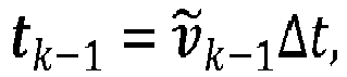

where ṽ k-1 and ω̃ k-1 are respectively an ego vehicle linear velocity estimate and an ego vehicle angular velocity estimate of the previous frame, Δt is a time difference between the two frames, and Exp(·): R3 → SO(3) is an exponential mapping of a three-dimensional rotation (R3 is a three-dimensional real number vector space, and SO(3) is a three-dimensional special orthogonal group). Then, the transformed previous frame of point cloud

 , the current point is classified as a random point and filtered out.
- In step 2, ego vehicle velocity estimation is performed, where the 4D millimeter-wave radar can obtain a Doppler velocity of each point, and the Doppler velocity is a radial component of a relative velocity between the radar and a target point. Based on the property of the Doppler velocity, a linear velocity and an angular velocity of an ego vehicle are estimated based on Doppler velocity information in a 4D radar point cloud.
- In step 2.1, static point extraction is performed. In addition to spatial information, the 4D radar can also obtain a Doppler velocity of each point in the point cloud. For an i th point in the 4D radar point cloud, if it is a stationary point with an absolute velocity of 0 in the real world, then its relative velocity to the radar is equal in magnitude and opposite in direction to the velocity of the radar. The Doppler velocity is a radial component of a relative velocity between the measured point and the 4D radar. Therefore, a relationship between the Doppler velocity of this point and the velocity of the radar is as follows:

where vr,i is the Doppler velocity of the i th point, d i = (cos θi cos ϕi, sin θi cos ϕi, sin ϕi ) T is a unit direction vector of the point relative to the radar, and vs is the velocity of the radar. - In addition, since the 4D radar is mounted on a vehicle, a relationship between the velocity of the radar and an ego vehicle velocity of the vehicle is as follows:

- where ts and Rs are respectively a mounting position and a pose of the 4D radar in a vehicle coordinate system, and ṽ ∈ R 3 and ω̃ ∈ R 3 are respectively an ego vehicle linear velocity and an ego vehicle angular velocity. In the real world, most points in the 4D radar point cloud are static points. Therefore, for all static points in the 4D radar point cloud, the Doppler velocity and the ego vehicle velocity both conform to the following equation:

- where m is a number of all the static points in the point cloud, I3×3 is a 3 × 3 unit matrix, and

- In step 2.2, least squares estimation is performed, where after the static points are extracted, the ego vehicle velocity is estimated based on the relationships between the Doppler velocities of all the static points and the ego vehicle velocity again and the least square method.
- In step 3, pose graph optimization is performed, where a current radar point cloud is registered with a local radar keyframe submap based on a normal distribution transformation, so as to obtain a millimeter-wave radar odometry factor; pre-integration is performed using the estimated ego vehicle velocity, so as to obtain a velocity pre-integration factor; and loop closure detection is performed to obtain a loop closure factor. Finally, the three factors are used to construct a pose graph, and an optimal pose is estimated based on graph optimization.
- In step 3.1, point cloud registration is performed based on the normal distribution transformation, where the relative transformation is estimated by direct matching between a current 4D radar point cloud and a keyframe submap.
- Due to that the 4D radar point cloud is too sparse, it is impossible to correctly estimate a pose only by matching of a single frame of point cloud. Therefore, a sliding window method is used to establish a denser radar submap using a plurality of keyframe point clouds. Specifically, if a translation or rotation from a last keyframe to a current point cloud exceeds a threshold, a current frame is selected as a new keyframe. Then, the new keyframe is added to the radar submap, and a node associated with the keyframe is added to the pose graph. When a number of keyframes in the submap exceeds a size of the window, the earliest keyframe is discarded. The radar submap established through this method can reflect local environmental features more clearly than a single frame of radar point cloud, improving the accuracy and robustness of point cloud registration.
- After the radar submap is established, the submap is evenly divided into grids of a same size, and a point cloud in each grid is modeled as a local normal distribution. Due to the sparsity of the 4D radar point cloud, a case where there are less than three points in a grid or points in the grid are collinear (coplanar) may easily occur after grid division, making it difficult to invert the covariance of the normal distribution. Therefore, measurement uncertainty of each point is comprehensively considered when computing a mean and a covariance of the normal distribution. An advantage of this is to reduce the degeneration effect of covariance, and point cloud information in a grid can be fully used even when there are very few points in the grid. Then, the current 4D radar point cloud is registered with the radar submap to estimate a relative pose transformation


where
- In step 3.2, velocity pre-integration is performed, where the relative pose transformation is computed using the estimated ego vehicle velocity, so that an additional reliable relative pose estimate is introduced, improving the accuracy and robustness of SLAM. An ego vehicle linear velocity and an ego vehicle angular velocity that are estimated at a moment t are respectively denoted as ṽ t and ω̃ t , with their estimated values being true values each plus a zero-mean Gaussian white noise, that is:


where ωt and WVt are respectively the true values of the angular velocity and the linear velocity in a world coordinate system,


- For a point cloud of each frame between keyframes corresponding to two consecutive moments i and j, an ego vehicle velocity estimate can be obtained. Therefore, integration is performed for all time periods Δt between moments i and j, and a position pj and a rotation Rj at a moment j can be computed based on a position pi and a rotation Ri at a moment i.


- From this, a relative rotation transformation ΔRij and a relative translation transformation Δpij between a moment i and a moment j can be obtained:


where


- Because δφij is a linear combination of a zero-mean Gaussian noise


where Log(·) : SO(3) → R3 is a logarithmic mapping of a three-dimensional rotation. - In step 3.3, loop closure detection is performed to identify places that have been previously reached, so as to reduce a cumulative drift. In polar coordinates, the 4D radar point cloud is divided into grids, a 3D point cloud is mapped to a 2D matrix, and a value of each element in the matrix is a maximum energy intensity of radar points in a corresponding grid. As the vehicle moves, a cosine distance between a 2D matrix of the current frame and a 2D matrix generated by each of all previous keyframes is continuously searched for and computed, and if the distance is less than a set threshold, it is considered that a loop closure has been detected. Once a loop closure is detected, a relative pose transformation


where L includes all loop closure frames,
- In step 3.4, graph optimization is performed, where the pose graph is established, error terms of all relative pose estimates are comprehensively considered, and optimal poses of the ego vehicle at all moments are estimated through graph optimization, implementing more accurate and robust localization and mapping. All nodes in the pose graph correspond to poses at different moments, and edges between the nodes correspond to relative pose transformations between different moments. The pose is expressed as x = (R, p) ∈ SE(3), where Rand p are a rotation and a translation, respectively. The poses at all moments are expressed as X = { x i }, i ∈, and the optimal pose .X'* is estimated by solving a nonlinear least squares problem:


whereincludes all moments, and eO, eV, eL respectively correspond to the errors of relative pose transformations obtained in different steps.
- Those skilled in the art know that, in addition to implementing the system and the apparatus as well as various modules thereof provided by the present invention in the form of pure computer-readable program code, the system and the apparatus as well as various modules thereof provided by the present invention can certainly be implemented in the form of logic gates, switches, application-specific integrated circuits, programmable logic controllers, and embedded microcontrollers by logically programming the method steps to implement the same program. Therefore, the system and the apparatus as well as various modules thereof provided by the present invention may be considered as a hardware component, and the modules included therein for implementing various programs may also be considered as structures within the hardware component. The modules for implementing various functions may also be considered as both software programs for implementing methods and structures within the hardware component.
- The specific embodiments of the present invention are described above. It should be understood that the present invention is not limited to the specific implementation described above, and various changes or modifications may be made by those skilled in the art within the scope of the claims, which does not affect the essential contents of the present invention. In case of no conflict, the embodiments in the present application and the features in the embodiments can be combined with each other.
Claims (10)
- A pose graph SLAM computation method based on a 4D millimeter-wave radar, the method comprising:step S1: extracting a ground point cloud, and comparing two consecutive frames of point clouds, to remove ghost points below the ground and random points;step S2: estimating a linear velocity and an angular velocity of a device based on Doppler velocity information in a 4D radar point cloud; andstep S3: estimating and constructing a pose graph using a relative pose transformation that is obtained through point cloud registration performed based on a normal distribution transformation, pre-integration performed using an estimated device velocity, and loop closure detection; and estimating an optimal pose through graph optimization.
- The pose graph SLAM computation method based on a 4D millimeter-wave radar according to claim 1, wherein in step S1,
the ground point cloud is extracted, and the two consecutive frames of point clouds are compared, to remove the ghost points below the ground and the unstable random points, so as to reduce noise in the 4D radar point cloud, wherein step S1 comprises the following steps:step S1.1: ghost point removal, wherein the ground point cloud is extracted from an original radar point cloud and the ghost points below the ground are filtered out;for the original radar point cloud= {P i }, i ∈ { 1, 2, ..., n } measured by a 4D radar, n is a number of points in the point cloud; a position of each point in a radar coordinate system is expressed as P i = (xi, yi, zi ) T = (ri cos θ i cos ϕ i ,ri sin θ i cos ϕ i , ri sin ϕ i ) T , wherein ri is a distance of the point measured by the 4D radar, θi is an azimuth angle of the point measured by the 4D radar, and ϕi is an elevation angle of the point measured by the 4D radar; andfor the original radar point cloud, a point with a distance less than a threshold δr and a height within a threshold δh near a mounting height of the radar is retained, an upward normal vector of each point is computed using a principal component analysis method, a point with a normal vector having an angle less than δn with a z-axis positive unit vector is retained, ground points are extracted using a random sample consensus algorithm, and the ghost points below the ground are filtered out; andstep S1.2: random point removal, wherein the random points are identified and filtered out by comparing a current point cloud and a previous frame of point cloud adjacent to the current point cloud, for the current point cloud and the previous frame of point cloud adjacent to the current point cloud, a pose transformation between the current point cloud and the previous frame of point cloud is computed based on the device velocity, the previous frame of point cloud is transformed into a coordinate system of the current frame, and if the transformed previous frame of point cloud does not exist within a preset range near a point in the current frame, the point is classified as a random point and filtered out; anda rotation transformation Rk-1 and a translation transformation tk-1 between the current point cloudand the previous frame of point cloud
 adjacent to the current point cloud are computed:

 wherein ṽ k-1 and ω̃ k-1 are respectively a device linear velocity estimate and a device angular velocity estimate of the previous frame, Δt is a time difference between the two frames, Exp(·): R 3 → SO(3) is an exponential mapping of a three-dimensional rotation, R3 is a three-dimensional real number vector space, SO(3) is a three-dimensional special orthogonal group , and

- The pose graph SLAM computation method based on a 4D millimeter-wave radar according to claim 1, wherein in step S2, the following steps are comprised:step S2.1: static point extraction, wherein for an i th point in the 4D radar point cloud, a relationship between a Doppler velocity of the point and a velocity of the radar is as follows:
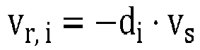 wherein vr,i is the Doppler velocity of the i th point, d i = (cos θi cos ϕi , sin θi cos ϕi , sin ϕi ) T is a unit direction vector of the point relative to the radar, and vs is the velocity of the radar; and a relationship between the velocity of the radar and the device velocity is as follows:
 wherein ts and Rs are respectively a mounting position and a pose of the 4D radar in a device coordinate system, ṽ ∈ R 3 and ω̃ ∈ R 3 are respectively the linear velocity and the angular velocity of the device, and for all static points in the 4D radar point cloud, the Doppler velocity and the device velocity both conform to the following equation:
 wherein m is a number of all the static points in the point cloud, I3×3 is a 3 × 3 unit matrix,
 step S2.2: least squares estimation, wherein after the static points are extracted, the device velocity is computed based on the relationships between the Doppler velocities of all the static points and the device velocity using the least square method.
 - The pose graph SLAM computation method based on a 4D millimeter-wave radar according to claim 1, wherein in step S3,
pose graph optimization is performed, wherein the pose graph is estimated and constructed using the relative pose transformation that is obtained through the point cloud registration, the velocity pre-integration, and the loop closure detection; and finally the optimal pose is estimated through the graph optimization, wherein the following steps are comprised:step S3.1: point cloud registration based on the normal distribution transformation, wherein a relative transformation is estimated by matching between a current 4D radar point cloud and a keyframe submap;a radar submap is established using a plurality of keyframe point clouds and a sliding window, if a translation or rotation from a last keyframe to a current point cloud exceeds a threshold, a current frame is selected as a new keyframe, the new keyframe is added to the radar submap,and when a number of keyframes in the submap exceeds a size of the window, the earliest keyframe is discarded; andafter the radar submap is established, the submap is evenly divided into grids of a same size, a point cloud in each grid is modeled as a local normal distribution, measurement uncertainty of each point is considered when computing a mean and a covariance of the normal distribution, and the current 4D radar point cloud is registered with the radar submap to compute a relative pose transformation that maximizes a distribution probability of the current point cloud in the submap, wherein an error of estimation of the pose transformation is eO; andstep S3.2: velocity pre-integration, wherein the relative pose transformation is computed based on the estimated device velocity, so that an additional reliable relative pose estimate is introduced, and a device linear velocity and a device angular velocity that are estimated at a moment t are respectively denoted as ṽ t and ω̃ t, with their estimated values being true values each plus a zero-mean Gaussian white noise:
 wherein ωt and WVt are respectively the true values of the angular velocity and the linear velocity in a world coordinate system,

- The pose graph SLAM computation method based on a 4D millimeter-wave radar according to claim 4, comprising the following steps:step S3.3: loop closure detection, wherein a position that has been previously reached is identified, in polar coordinates, the 4D radar point cloud is divided into grids, a 3D point cloud is mapped to a 2D matrix, a value of each element in the matrix is a maximum energy intensity of radar points in a corresponding grid, as the device moves, a cosine distance between a 2D matrix of the current frame and a 2D matrix generated by each of all previous keyframes is continuously searched for and computed, and if the distance is less than a set threshold, it is considered that a loop closure has been detected; when a loop closure is detected, a relative pose transformation between the current frame and a submap composed of a loop closure frame and nearby keyframes is computed; and an error of estimation of the pose transformation is eL; andstep S3.4: graph optimization, wherein the pose graph is established, error terms of relative pose estimates at all moments are considered, optimal poses of the device at all moments are estimated through graph optimization, all nodes in the pose graph correspond to poses at different moments, and edges between the nodes correspond to relative pose transformations between different moments; and all the poses are expressed as X = { x i }, i ∈, and the optimal pose .X'* is estimated by solving a nonlinear least squares problem:

 whereincomprises all moments, and eO, eV, eL respectively correspond to the errors of relative pose transformations obtained in different steps.
- A pose graph SLAM computation system based on a 4D millimeter-wave radar, comprising:a module M1 configured to extract a ground point cloud, and compare two consecutive frames of point clouds, to remove ghost points below the ground and random points;a module M2 configured to estimate a linear velocity and an angular velocity of a device based on Doppler velocity information in a 4D radar point cloud; anda module M3 configured to estimate and construct a pose graph using a relative pose transformation that is obtained through point cloud registration performed based on a normal distribution transformation, pre-integration performed using an estimated device velocity, andloop closure detection; and estimate an optimal pose through graph optimization.
- The pose graph SLAM computation system based on a 4D millimeter-wave radar according to claim 6, wherein in the module M1,the ground point cloud is extracted, and the two consecutive frames of point clouds are compared, to remove the ghost points below the ground and the unstable random points, so as to reduce noise in the 4D radar point cloud, whereina module M1.1 is configured to perform the following operation: ghost point removal, wherein the ground point cloud is extracted from an original radar point cloud and the ghost points below the ground are filtered out;for the original radar point cloud= {P i }, i ∈ { 1, 2, ..., n } measured by a 4D radar, n is a number of points in the point cloud;
 a position of each point in a radar coordinate system is expressed as P i = (xi, yi, zi ) T = (ri cos θ i cos ϕ i , ri sin θ i cos ϕ i , ri sin ϕ i ) T , wherein ri is a distance of the point measured by the 4D radar, θi is an azimuth angle of the point measured by the 4D radar, and ϕi is an elevation angle of the point measured by the 4D radar; andfor the original radar point cloud, a point with a distance less than a threshold δr and a height within a threshold δh near a mounting height of the radar is retained, an upward normal vector of each point is computed using a principal component analysis method, a point with a normal vector having an angle less than δn with a z-axis positive unit vector is retained, ground points are extracted using a random sample consensus algorithm, and the ghost points below the ground are filtered out; anda module M1.2 is configured to perform the following operation: random point removal, wherein the random points are identified and filtered out by comparing a current point cloud and a previous frame of point cloud adjacent to the current point cloud, for the current point cloud and the previous frame of point cloud adjacent to the current point cloud, a pose transformation between the current point cloud and the previous frame of point cloud is computed based on the device velocity, the previous frame of point cloud is transformed into a coordinate system of the current frame, and if the transformed previous frame of point cloud does not exist within a preset range near a point in the current frame, the point is classified as a random point and filtered out; anda rotation transformation Rk-1 and a translation transformation tk-1 between the current point cloudand the previous frame of point cloud
 adjacent to the current point cloud are computed:

 wherein ṽ k-1 and ω̃ k-1 are respectively a device linear velocity estimate and a device angular velocity estimate of the previous frame, Δt is a time difference between the two frames, Exp(·): R3 → SO(3) is an exponential mapping of a three-dimensional rotation, R3 is a three-dimensional real number vector space, SO(3) is a three-dimensional special orthogonal group , and

- The pose graph SLAM computation system based on a 4D millimeter-wave radar according to claim 6, wherein in the module M2,
a module M2.1 is configured to perform the following operation: static point extraction, wherein for an i th point in the 4D radar point cloud, a relationship between a Doppler velocity of the point and a velocity of the radar is as follows:vr,i = -di · vs wherein vr,i is the Doppler velocity of the i th point, d i = (cos θi cos ϕi, sin θi cos ϕi, sin ϕi ) T is a unit direction vector of the point relative to the radar, and vs is the velocity of the radar; anda relationship between the velocity of the radar and the device velocity is as follows: wherein ts and Rs are respectively a mounting position and a pose of the 4D radar in a device coordinate system, ṽ ∈ R 3 and ω̃ ∈ R 3 are respectively the linear velocity and the angular velocity of the device, and for all static points in the 4D radar point cloud, the Doppler velocity and the device velocity both conform to the following equation:
 wherein m is a number of all the static points in the point cloud, I3×3 is a 3 × 3 unit matrix,
 a module M2.2 is configured to perform the following operation: least squares estimation, wherein after the static points are extracted, the device velocity is computed based on the relationships between the Doppler velocities of all the static points and the device velocity using the least square method.
 - The pose graph SLAM computation system based on a 4D millimeter-wave radar according to claim 6, wherein in the module M3,pose graph optimization is performed, wherein the pose graph is estimated and constructed using the relative pose transformation that is obtained through the point cloud registration, the velocity pre-integration, and the loop closure detection; and finally the optimal pose is estimated through the graph optimization, whereina module M3.1 is configured to perform the following operation: point cloud registration based on the normal distribution transformation, wherein a relative transformation is estimated by matching between a current 4D radar point cloud and a keyframe submap;a radar submap is established using a plurality of keyframe point clouds and a sliding window, if a translation or rotation from a last keyframe to a current point cloud exceeds a threshold, a current frame is selected as a new keyframe, the new keyframe is added to the radar submap, and when a number of keyframes in the submap exceeds a size of the window, the earliest keyframe is discarded; andafter the radar submap is established, the submap is evenly divided into grids of a same size, a point cloud in each grid is modeled as a local normal distribution, measurement uncertainty of each point is considered when computing a mean and a covariance of the normal distribution, and the current 4D radar point cloud is registered with the radar submap to compute a relative pose transformation that maximizes a distribution probability of the current point cloud in the submap, wherein an error of estimation of the pose transformation is eO; anda module M3.2 is configured to perform the following operation: velocity pre-integration, wherein the relative pose transformation is computed based on the estimated device velocity, so that an additional reliable relative pose estimate is introduced, and a device linear velocity and a device angular velocity that are estimated at a moment t are respectively denoted as ṽ t and ω̃ t, with their estimated values being true values each plus a zero-mean Gaussian white noise:

 wherein ωt and Wvt are respectively the true values of the angular velocity and the linear velocity in a world coordinate system,

- The pose graph SLAM computation system based on a 4D millimeter-wave radar according to claim 9, whereina module M3.3 is configured to perform the following operation: loop closure detection, wherein a position that has been previously reached is identified, in polar coordinates, the 4D radar point cloud is divided into grids, a 3D point cloud is mapped to a 2D matrix, a value of each element in the matrix is a maximum energy intensity of radar points in a corresponding grid, as the device moves, a cosine distance between a 2D matrix of the current frame and a 2D matrix generated by each of all previous keyframes is continuously searched for and computed, and if the distance is less than a set threshold, it is considered that a loop closure has been detected; when a loop closure is detected, a relative pose transformation between the current frame and a submap composed of a loop closure frame and nearby keyframes is computed; and an error of estimation of the pose transformation is eL; anda module M3.4 is configured to perform the following operation: graph optimization, wherein the pose graph is established, error terms of relative pose estimates at all moments are considered, optimal poses of the device at all moments are estimated through graph optimization, all nodes in the pose graph correspond to poses at different moments, and edges between the nodes correspond to relative pose transformations between different moments; and all the poses are expressed as X = { x i }, i ∈, and the optimal pose .X'* is estimated by solving a nonlinear least squares problem:

 whereincomprises all moments, and eO, eV, eL respectively correspond to the errors of relative pose transformations obtained in different steps.
Applications Claiming Priority (1)
| Application Number | Priority Date | Filing Date | Title |
|---|---|---|---|
| CN202310532630.2A CN116359905A (en) | 2023-05-11 | 2023-05-11 | Calculation method and system of pose graph SLAM based on 4D millimeter-wave radar |
Publications (2)
| Publication Number | Publication Date |
|---|---|
| EP4462153A2 true EP4462153A2 (en) | 2024-11-13 |
| EP4462153A3 EP4462153A3 (en) | 2024-11-20 |
Family
ID=86938103
Family Applications (1)
| Application Number | Title | Priority Date | Filing Date |
|---|---|---|---|
| EP24174589.2A Pending EP4462153A3 (en) | 2023-05-11 | 2024-05-07 | Pose graph slam computation method and system based on 4d millimeter-wave radar |
Country Status (3)
| Country | Link |
|---|---|
| US (1) | US20240378745A1 (en) |
| EP (1) | EP4462153A3 (en) |
| CN (1) | CN116359905A (en) |
Cited By (1)
| Publication number | Priority date | Publication date | Assignee | Title |
|---|---|---|---|---|
| CN121632031A (en) * | 2026-02-02 | 2026-03-10 | 华路易云科技有限公司 | Static Target Deformation Monitoring and Power-Off Self-Recovery Method Based on 4D Millimeter-Wave Radar |
Families Citing this family (13)
| Publication number | Priority date | Publication date | Assignee | Title |
|---|---|---|---|---|
| CN117518156A (en) * | 2023-11-07 | 2024-02-06 | 上海交通大学 | Self-pose estimation method and system |
| CN117315268B (en) * | 2023-11-27 | 2024-02-09 | 武汉大学 | SLAM method and system based on millimeter wave radar |
| CN117590371B (en) * | 2024-01-18 | 2024-03-29 | 上海几何伙伴智能驾驶有限公司 | Method to realize global parking space status detection based on 4D millimeter wave imaging radar |
| CN117593650B (en) * | 2024-01-18 | 2024-04-26 | 上海几何伙伴智能驾驶有限公司 | Moving point filtering visual SLAM method based on 4D millimeter wave radar and SAM image segmentation |
| CN118409331A (en) * | 2024-04-26 | 2024-07-30 | 理工雷科智途(北京)科技有限公司 | A laser SLAM rapid repositioning method and device suitable for underground mining environments |
| CN119245695B (en) * | 2024-12-04 | 2025-03-11 | 新石器慧通(北京)科技有限公司 | Radar-assisted inertial measurement unit anomaly detection method and its application |
| CN119354205B (en) * | 2024-12-25 | 2025-05-02 | 哈尔滨工业大学(威海) | Unmanned fire-extinguishing robot navigation method and device based on 4D millimeter wave radar |
| CN119933488B (en) * | 2024-12-27 | 2025-12-30 | 南京理工大学 | Intelligent detection and control method of 4D millimeter wave radar for pedestrians and automatic door leaves |
| CN119805446B (en) * | 2025-01-20 | 2025-08-08 | 东南大学 | Visual-aided multistage radar inertial positioning method and system in degradation environment |
| CN120047544B (en) * | 2025-04-25 | 2025-08-05 | 浙江迈睿机器人有限公司 | Joint calibration method, system and device based on AGV bottom camera and laser radar |
| CN120630199B (en) * | 2025-08-13 | 2025-11-07 | 理工雷科智途(北京)科技有限公司 | Underground environment laser radar and millimeter wave radar collaborative SLAM method |
| CN121147429B (en) * | 2025-08-29 | 2026-05-12 | 江淮前沿技术协同创新中心 | Mapping method and device based on 4D millimeter wave radar and computer readable medium |
| CN120899218B (en) * | 2025-10-11 | 2025-12-05 | 合肥雷能信息技术有限公司 | Human body activity state analysis system and method for multi-radar data stitching |
Citations (1)
| Publication number | Priority date | Publication date | Assignee | Title |
|---|---|---|---|---|
| CN111522043A (en) | 2020-04-30 | 2020-08-11 | 北京联合大学 | A fast rematching and positioning method for unmanned vehicle lidar |
Family Cites Families (4)
| Publication number | Priority date | Publication date | Assignee | Title |
|---|---|---|---|---|
| US11506512B2 (en) * | 2019-05-22 | 2022-11-22 | TDK Japan | Method and system using tightly coupled radar positioning to improve map performance |
| CN113781582B (en) * | 2021-09-18 | 2023-09-19 | 四川大学 | Synchronous positioning and map creation method based on joint calibration of lidar and inertial navigation |
| CN115343722B (en) * | 2022-07-07 | 2025-04-29 | 东南大学 | A lidar SLAM method based on loop closure detection in large-scale scenes |
| CN115727860B (en) * | 2022-11-17 | 2025-03-18 | 中国科学院空天信息创新研究院 | A multi-view fusion method for simultaneous positioning and mapping of automotive radar |
-
2023
- 2023-05-11 CN CN202310532630.2A patent/CN116359905A/en active Pending
-
2024
- 2024-05-07 EP EP24174589.2A patent/EP4462153A3/en active Pending
- 2024-05-10 US US18/661,026 patent/US20240378745A1/en active Pending
Patent Citations (1)
| Publication number | Priority date | Publication date | Assignee | Title |
|---|---|---|---|---|
| CN111522043A (en) | 2020-04-30 | 2020-08-11 | 北京联合大学 | A fast rematching and positioning method for unmanned vehicle lidar |
Non-Patent Citations (3)
| Title |
|---|
| D. KELLNERM. BARJENBRUCHJ. KLAPPSTEINJ. DICKMANNK. DIETMAYER: "Instantaneous ego-motion estimation using Doppler radar", 16TH INTERNATIONAL IEEE CONFERENCE ON INTELLIGENT TRANSPORTATION SYSTEMS, October 2013 (2013-10-01), pages 869 - 874, XP055604073, ISSN: 2153-0017, DOI: 10.1109/ITSC.2013.6728341 |
| P.-C. KUNGC.-C. WANGW.-C. LIN: "A Normal Distribution Transform-Based Radar Odometry Designed For Scanning and Automotive Radars", 2021 IEEE INTERNATIONAL CONFERENCE ON ROBOTICS AND AUTOMATION (ICRA). XI'AN, CHINA: IEEE, May 2021 (2021-05-01), pages 14417 - 14423 |
| Z. HONGY. PETILLOTS. WANG: "RadarSLAM: Radar based Large-Scale SLAM in All Weathers", 2020 IEEE/RSJ INTERNATIONAL CONFERENCE ON INTELLIGENT ROBOTS AND SYSTEMS (IROS, October 2020 (2020-10-01), pages 5164 - 5170, ISSN: 2153-086 |
Cited By (1)
| Publication number | Priority date | Publication date | Assignee | Title |
|---|---|---|---|---|
| CN121632031A (en) * | 2026-02-02 | 2026-03-10 | 华路易云科技有限公司 | Static Target Deformation Monitoring and Power-Off Self-Recovery Method Based on 4D Millimeter-Wave Radar |
Also Published As
| Publication number | Publication date |
|---|---|
| EP4462153A3 (en) | 2024-11-20 |
| US20240378745A1 (en) | 2024-11-14 |
| CN116359905A (en) | 2023-06-30 |
Similar Documents
| Publication | Publication Date | Title |
|---|---|---|
| US20240378745A1 (en) | Pose graph SLAM computation method and system based on 4D millimeter-wave radar | |
| Ebadi et al. | DARE-SLAM: Degeneracy-aware and resilient loop closing in perceptually-degraded environments | |
| Wang et al. | Visual semantic localization based on hd map for autonomous vehicles in urban scenarios | |
| US9864927B2 (en) | Method of detecting structural parts of a scene | |
| Chen et al. | Velodyne-based curb detection up to 50 meters away | |
| Lu et al. | Sharing heterogeneous spatial knowledge: Map fusion between asynchronous monocular vision and lidar or other prior inputs | |
| Liu et al. | A multisensor fusion with automatic vision–LiDAR calibration based on factor graph joint optimization for SLAM | |
| Du et al. | Real-time simultaneous localization and mapping with LiDAR intensity | |
| Nezhadarya et al. | BoxNet: A Deep Learning Method for 2D Bounding Box Estimation from Bird's-Eye View Point Cloud | |
| Zhang et al. | Multiple vehicle-like target tracking based on the velodyne lidar | |
| Wu et al. | MSTSL: Multi-sensor based two-step localization in geometrically symmetric environments | |
| Aryal | Object detection, classification, and tracking for autonomous vehicle | |
| Zhou et al. | Terrain traversability mapping based on lidar and camera fusion | |
| Zhong et al. | Colrio: Lidar-ranging-inertial centralized state estimation for robotic swarms | |
| Gu et al. | Robust visual localization system with HD map based on joint probabilistic data association | |
| Stübler et al. | Feature-based mapping and self-localization for road vehicles using a single grayscale camera | |
| Chen et al. | Large-scale underground mine positioning and mapping with LiDAR-based semantic intersection detection | |
| Aggarwal | On the use of artificial intelligence techniques in transportation systems | |
| Wu et al. | Precise pose graph localization with sparse point and lane features | |
| Koch et al. | Ground robot navigation using uncalibrated cameras | |
| Opromolla et al. | PCA‐Based Line Detection from Range Data for Mapping and Localization‐Aiding of UAVs | |
| Aggarwal | Machine vision based SelfPosition estimation of mobile robots | |
| Haoran et al. | Mvm3det: A novel method for multi-view monocular 3d detection | |
| Chen et al. | Multiple-object tracking based on monocular camera and 3-D lidar fusion for autonomous vehicles | |
| Liang et al. | A semantic knowledge database-based localization method for UAV inspection in perceptual-degraded underground mine |
Legal Events
| Date | Code | Title | Description |
|---|---|---|---|
| PUAI | Public reference made under article 153(3) epc to a published international application that has entered the european phase |
Free format text: ORIGINAL CODE: 0009012 |
|
| STAA | Information on the status of an ep patent application or granted ep patent |
Free format text: STATUS: THE APPLICATION HAS BEEN PUBLISHED |
|
| PUAL | Search report despatched |
Free format text: ORIGINAL CODE: 0009013 |
|
| AK | Designated contracting states |
Kind code of ref document: A2 Designated state(s): AL AT BE BG CH CY CZ DE DK EE ES FI FR GB GR HR HU IE IS IT LI LT LU LV MC ME MK MT NL NO PL PT RO RS SE SI SK SM TR |
|
| AK | Designated contracting states |
Kind code of ref document: A3 Designated state(s): AL AT BE BG CH CY CZ DE DK EE ES FI FR GB GR HR HU IE IS IT LI LT LU LV MC ME MK MT NL NO PL PT RO RS SE SI SK SM TR |
|
| RIC1 | Information provided on ipc code assigned before grant |
Ipc: G01S 13/931 20200101ALI20241017BHEP Ipc: G01S 13/89 20060101ALI20241017BHEP Ipc: G01S 13/58 20060101ALI20241017BHEP Ipc: G01S 13/52 20060101ALI20241017BHEP Ipc: G01S 13/42 20060101ALI20241017BHEP Ipc: G01S 7/41 20060101AFI20241017BHEP |
|
| STAA | Information on the status of an ep patent application or granted ep patent |
Free format text: STATUS: REQUEST FOR EXAMINATION WAS MADE |
|
| 17P | Request for examination filed |
Effective date: 20250325 |