EP4462110A1 - Evaluation device and evaluation method for thermal shrinkage of separator - Google Patents
Evaluation device and evaluation method for thermal shrinkage of separator Download PDFInfo
- Publication number
- EP4462110A1 EP4462110A1 EP23868413.8A EP23868413A EP4462110A1 EP 4462110 A1 EP4462110 A1 EP 4462110A1 EP 23868413 A EP23868413 A EP 23868413A EP 4462110 A1 EP4462110 A1 EP 4462110A1
- Authority
- EP
- European Patent Office
- Prior art keywords
- separator
- separator sample
- thermal shrinkage
- sample
- axis direction
- Prior art date
- Legal status (The legal status is an assumption and is not a legal conclusion. Google has not performed a legal analysis and makes no representation as to the accuracy of the status listed.)
- Granted
Links
Images


Classifications
-
- H—ELECTRICITY
- H01—ELECTRIC ELEMENTS
- H01M—PROCESSES OR MEANS, e.g. BATTERIES, FOR THE DIRECT CONVERSION OF CHEMICAL ENERGY INTO ELECTRICAL ENERGY
- H01M50/00—Constructional details or processes of manufacture of the non-active parts of electrochemical cells other than fuel cells, e.g. hybrid cells
- H01M50/40—Separators; Membranes; Diaphragms; Spacing elements inside cells
- H01M50/489—Separators, membranes, diaphragms or spacing elements inside the cells, characterised by their physical properties, e.g. swelling degree, hydrophilicity or shut down properties
-
- G—PHYSICS
- G01—MEASURING; TESTING
- G01B—MEASURING LENGTH, THICKNESS OR SIMILAR LINEAR DIMENSIONS; MEASURING ANGLES; MEASURING AREAS; MEASURING IRREGULARITIES OF SURFACES OR CONTOURS
- G01B11/00—Measuring arrangements characterised by the use of optical techniques
- G01B11/02—Measuring arrangements characterised by the use of optical techniques for measuring length, width or thickness
-
- G—PHYSICS
- G01—MEASURING; TESTING
- G01B—MEASURING LENGTH, THICKNESS OR SIMILAR LINEAR DIMENSIONS; MEASURING ANGLES; MEASURING AREAS; MEASURING IRREGULARITIES OF SURFACES OR CONTOURS
- G01B11/00—Measuring arrangements characterised by the use of optical techniques
- G01B11/02—Measuring arrangements characterised by the use of optical techniques for measuring length, width or thickness
- G01B11/022—Measuring arrangements characterised by the use of optical techniques for measuring length, width or thickness by means of tv-camera scanning
-
- G—PHYSICS
- G01—MEASURING; TESTING
- G01B—MEASURING LENGTH, THICKNESS OR SIMILAR LINEAR DIMENSIONS; MEASURING ANGLES; MEASURING AREAS; MEASURING IRREGULARITIES OF SURFACES OR CONTOURS
- G01B11/00—Measuring arrangements characterised by the use of optical techniques
- G01B11/16—Measuring arrangements characterised by the use of optical techniques for measuring the deformation in a solid, e.g. optical strain gauge
-
- G—PHYSICS
- G01—MEASURING; TESTING
- G01B—MEASURING LENGTH, THICKNESS OR SIMILAR LINEAR DIMENSIONS; MEASURING ANGLES; MEASURING AREAS; MEASURING IRREGULARITIES OF SURFACES OR CONTOURS
- G01B11/00—Measuring arrangements characterised by the use of optical techniques
- G01B11/16—Measuring arrangements characterised by the use of optical techniques for measuring the deformation in a solid, e.g. optical strain gauge
- G01B11/165—Measuring arrangements characterised by the use of optical techniques for measuring the deformation in a solid, e.g. optical strain gauge by means of a grating deformed by the object
-
- G—PHYSICS
- G01—MEASURING; TESTING
- G01N—INVESTIGATING OR ANALYSING MATERIALS BY DETERMINING THEIR CHEMICAL OR PHYSICAL PROPERTIES
- G01N25/00—Investigating or analyzing materials by the use of thermal means
- G01N25/16—Investigating or analyzing materials by the use of thermal means by investigating thermal coefficient of expansion
Definitions
- the present disclosure relates to a separator thermal shrinkage rate evaluation device and evaluation method that can easily evaluate the thermal shrinkage rate of a separator that is one of the basic materials of a battery.
- a separator is one of the basic materials of a battery that stores battery energy. Such a separator is located between a positive electrode and a negative electrode of the battery, physically blocks contact between the two electrodes, and selectively allows only small lithium ions to pass therethrough, making it essential for safe use of electrical energy.
- a separator thermal shrinkage rate evaluation item which is one of the items for evaluating the stability of the separator, is a method for evaluating the degree of shrinkage of the separator due to heat.
- a separator sample is shrunk at specific temperature and time, and then a worker directly measures the degree of shrinkage by using a ruler.
- the thermal shrinkage rate evaluation method in the related art as described above is based on the concept of simply measuring the length of the separator sample, and has the disadvantage of low accuracy and reliability and very low evaluation speed.
- measuring a shrinkage rate may be difficult.
- Embodiments of the present disclosure intend to provide a separator thermal shrinkage rate evaluation device and evaluation method that can easily evaluate the thermal shrinkage rate of a separator.
- a separator thermal shrinkage rate evaluation device for implementing the object described above may include: a mounting table on which a separator sample to be evaluated is placed; a lighting unit that emits light toward at least one of a top surface or a bottom surface of the separator sample; an imaging unit that takes an image of the separator sample; and an evaluation unit that determines a degree of shrinkage of the separator sample by comparing values of a length in each direction of the separator sample measured through the image taken by the imaging unit with a reference value before thermal shrinkage.
- At least four reference points constituting a square among a plurality of points representing a border of the separator sample may be set on the separator sample.
- the separator sample may be formed into a square shape, and the reference point may be a vertex of the separator sample.
- the evaluation unit may include: a first measurement range set so that two points closest to a center of a plane of the separator sample in a Y-axis direction are selected from the four reference points, parallel virtual horizontal lines respectively passing through the selected two points are formed, and a plurality of lengths of the separator sample in an X-axis direction are measured in a range between the virtual horizontal lines; and a second measurement range set so that two points closest to the center of the plane of the separator sample in the X-axis direction are selected from the four reference points, parallel virtual vertical lines respectively passing through the selected two points are formed, and a plurality of lengths of the separator sample in the Y-axis direction are measured in a range between the virtual vertical lines.
- the evaluation unit may select, as a measurement value, the shortest length among the plurality of lengths measured in the first measurement range and the second measurement range.
- the evaluation unit may ascertain the separator sample by using a difference in brightness or gray scale of the taken image.
- the lighting unit may include: a first lighting unit that is provided below the mounting table and emits light toward a bottom surface of the separator sample; and a second lighting unit that is provided above the mounting table and emits light toward a top surface of the separator sample.
- the first lighting unit may be integrally inserted inside the mounting table and may emit light toward an entire area of the mounting table.
- the imaging unit may be provided above the mounting table.
- a separator thermal shrinkage rate evaluation method may include: a first step of cutting a separator sample to be evaluated to a reference value of a predetermined size and setting at least four reference points on an upper surface of the cut separator sample; a second step of shrinking the separator sample by applying heat at a predetermined temperature for a predetermined period of time; a third step of placing the shrunk separator sample on an upper surface of a mounting table and taking an image of the separator sample; a fourth step of selecting two points closest to a center of a plane of the separator sample in a Y-axis direction among the four reference points on the basis of the taken image, forming parallel virtual horizontal lines respectively passing through the two selected points, and measuring a length of the separator sample in an X-axis direction in a range between the virtual horizontal lines; a fifth step of selecting two points closest to the center of the plane of the separator sample in the X-axis direction among the four reference points on the basis of the taken image, forming parallel virtual vertical lines respectively
- the shortest length of the lengths measured in the X-axis direction and the Y-axis direction may be selected as a measurement value.
- a separator thermal shrinkage rate evaluation device and evaluation method configured as described above according to the present disclosure have the advantage of setting first and second measurement ranges in an X-axis direction and a Y-axis direction, respectively, on the basis of four reference points set on a separator sample forming a square, and measuring a thermal shrinkage rate by comparing measured values obtained by measuring the shortest lengths of the separator sample in the measurement ranges with a reference value, thereby obtaining more accurate data.
- FIG. 1 is an overall schematic diagram illustrating a separator thermal shrinkage rate evaluation device according to the present disclosure
- FIG. 2 is a schematic perspective view of the separator thermal shrinkage rate evaluation device according to the present disclosure.
- a separator thermal shrinkage rate evaluation device 100 includes a mounting table 110, a lighting unit 120, an imaging unit 140, and an evaluation unit 150.
- the mounting table 110 may be formed as a plate having a top surface on which a separator sample 1 to be evaluated can be placed.
- a mounting table 110 may be made of a transparent or semi-transparent material so that the boundary of the separator sample 1 can be easily ascertained through the lighting unit 120 to be described below.
- the mounting table 110 is not limited thereto and can be variously changed and applied.
- the separator sample 1 placed on the mounting table 110 may be formed into, for example, a square shape (5 cm ⁇ 5 cm) so that the degree of shrinkage may be easily measured, and on an upper surface of the mounting table 110, the separator sample 1 shrunk due to heat may be placed.
- a size reference value R before shrinkage of the separator sample 1 may be a standardized square shape, and accordingly, the degree of shrinkage may be evaluated by measuring the length in a specific direction of the separator sample 1 after shrinkage through the thermal shrinkage rate evaluation device 100. A more specific shrinkage evaluation method is described below.
- At least four reference points P1 to P4 constituting a square among a plurality of points representing the border of the sample may be set on the upper surface of the separator sample 1.
- the present disclosure illustrates and describes an example in which the reference points P1 to P4 before and after thermal shrinkage of the separator sample 1 are formed at the same positions (vertices).
- the reference points P1 to P4 are not limited thereto, and may be displayed in the form of marks at predetermined positions formed on the upper surface of the separator sample 1 in various shapes, rather than at the vertices of a square.
- the lighting unit 120 may emit light toward at least one of a top surface or a bottom surface of the separator sample 1.
- the lighting unit 120 may include a first lighting unit 121 that is provided below the mounting table 110 and emits light toward the bottom surface of the separator sample 1.
- the first lighting unit 121 may be integrally inserted inside the mounting table 110 and may emit light toward an entire area of the mounting table 110.
- the lighting unit 120 may include a second lighting unit 122 that is provided above the mounting table 110 and emits light toward the top surface of the separator sample 1.
- At least one second lighting unit 122 may be installed directly above the mounting table 110, or the second lighting unit 122 may be installed symmetrically on both sides of an upper part of the mounting table 110 to emit light obliquely toward the separator sample 1.
- the present disclosure does not limit the specific arrangement structure of the second lighting unit 122.
- the imaging unit 140 takes an image of the separator sample 1.
- the imaging unit 140 may be spaced apart from a portion directly above the separator sample 1 placed on the upper surface of the mounting table 110.
- Such an imaging unit 140 may take an image of the separator sample 1 irradiated with light through the first lighting unit 121 and the second lighting unit 122.
- the evaluation unit 150 measures the thermal shrinkage rate of the separator sample 1 through the image taken by the imaging unit 140. Such an evaluation unit 150 may determine the degree of shrinkage by comparing measurement values L1 and L2 of the length in each direction of the separator sample 1 on the basis of the reference points P1 to P4 set on the upper surface of the separator sample 1 with a reference value R (see FIG. 3 ) before thermal shrinkage.
- the evaluation unit 150 may ascertain the separator sample 1 by using the difference in brightness or gray scale of the taken image.
- the evaluation unit 150 may set a first measurement range d1 (see FIG. 4 ) for measuring the length of the separator sample 1 in the X-axis direction and a second measurement range d2 (see FIG. 5 ) for measuring the length of the separator sample 1 in the Y-axis direction.
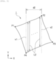
- the first measurement range d1 may be set by selecting the two points P1 and P3 closest to the center of a plane of the separator sample 1 in the Y-axis direction among the four reference points set on the upper surface of the separator sample 1 and forming parallel virtual horizontal lines h1 and h2 passing through the selected two points P1 and P3, respectively.
- a plurality of lengths L1 of the separator sample 1 in the X-axis direction may be measured.
- the evaluation unit 150 may select, as a measurement value L1, the shortest length among the plurality of lengths L1 measured in the first measurement range d1.
- the second measurement range d2 may be set by selecting the two points P2 and P4 closest to the center of the plane of the separator sample 1 in the X-axis direction among the four reference points P1 to P4 set on the upper surface of the separator sample 1 and forming parallel virtual vertical lines v1 and v2 passing through the selected two points P2 and P4, respectively.
- a plurality of lengths L2 of the separator sample 1 in the Y-axis direction may be measured.
- the evaluation unit 150 may select, as a measurement value L2, the shortest length among the plurality of lengths L2 measured in the second measurement range d2, like the case of the first measurement range d1.
- the separator sample 1 to be evaluated is cut to a reference value R of a predetermined size, and at least four reference points P1 to P4 are set on the upper surface of the cut separator sample 1 (see FIG. 3 ).
- the cut separator sample 1 is shrunk by applying heat at a predetermined temperature and for a predetermined period of time.
- the shrunken separator sample 1 is placed on the upper surface of the mounting table 110 and an image of the separator sample 1 is taken through the imaging unit 140 (see FIG. 2 ).
- the evaluation unit 150 selects the two points P1 and P3 closest to the center of the plane of the separator sample 1 in the Y-axis direction among the four reference points P1 to P4 on the basis of the taken image. Subsequently, the evaluation unit 150 forms the parallel virtual horizontal lines h1 and h2 respectively passing through the two selected points P1 and P3, and measures the length L1 of the separator sample 1 in the X-axis direction in the first measurement range d1 between the virtual horizontal lines h1 and h2 (see FIG. 4 ).
- the evaluation unit 150 selects the two points P2 and P4 closest to the center of the plane of the separator sample 1 in the X-axis direction among the four reference points P1 to P4 on the basis of the taken image. Subsequently, the evaluation unit 150 forms the parallel virtual vertical lines v1 and v2 respectively passing through the two selected points P2 and P4, and measures the length L2 of the separator sample 1 in the Y-axis direction in the second measurement range d2 between the virtual vertical lines v1 and v2 (see FIG. 5 ).
- the evaluation unit 150 may select the shortest lengths among the lengths measured in the first measurement range d1 and the second measurement range d2 as the measurement values L1 and L2 in the X-axis direction and the Y-axis direction, respectively.
- the evaluation unit 150 calculates a thermal shrinkage rate by comparing the measured length values L1 and L2 in the X-axis direction and the Y-axis direction with the reference value R (see FIG. 3 ).
- the separator thermal shrinkage rate evaluation device 100 configured as described above according to the present disclosure sets the first and second measurement ranges d1 and d2 in the X-axis direction and the Y-axis direction, respectively, on the basis of the four reference points P1 to P4 set on the separator sample 1 forming a square, and measures a thermal shrinkage rate by comparing the measured values L1 and L2 obtained by measuring the shortest lengths of the separator sample 1 in the measurement ranges with the reference value R, thereby obtaining more accurate data.
Landscapes
- Physics & Mathematics (AREA)
- General Physics & Mathematics (AREA)
- Chemical & Material Sciences (AREA)
- Health & Medical Sciences (AREA)
- General Chemical & Material Sciences (AREA)
- Electrochemistry (AREA)
- Chemical Kinetics & Catalysis (AREA)
- Life Sciences & Earth Sciences (AREA)
- Analytical Chemistry (AREA)
- Biochemistry (AREA)
- General Health & Medical Sciences (AREA)
- Immunology (AREA)
- Pathology (AREA)
- Investigating Or Analyzing Materials Using Thermal Means (AREA)
- Cell Separators (AREA)
Abstract
Description
- The present disclosure claims the benefit of the filing date of
Korean Patent Application No. 10-2022-0119715, filled with the Korean Intellectual Property Office on September 22, 2022 - The present disclosure relates to a separator thermal shrinkage rate evaluation device and evaluation method that can easily evaluate the thermal shrinkage rate of a separator that is one of the basic materials of a battery.
- In general, a separator is one of the basic materials of a battery that stores battery energy. Such a separator is located between a positive electrode and a negative electrode of the battery, physically blocks contact between the two electrodes, and selectively allows only small lithium ions to pass therethrough, making it essential for safe use of electrical energy.
- Recently, as fires occur in vehicles and facilities using large-capacity batteries, the safety of the batteries has become more important. Accordingly, the safety standards of the separator are also being strengthened.
- A separator thermal shrinkage rate evaluation item, which is one of the items for evaluating the stability of the separator, is a method for evaluating the degree of shrinkage of the separator due to heat.
- Specifically, in a method for measuring a thermal shrinkage rate in the related art, a separator sample is shrunk at specific temperature and time, and then a worker directly measures the degree of shrinkage by using a ruler.
- However, the thermal shrinkage rate evaluation method in the related art as described above is based on the concept of simply measuring the length of the separator sample, and has the disadvantage of low accuracy and reliability and very low evaluation speed. In particular, when the separator sample is shrunk and then does not maintain a square shape with an interior angle of 90°, measuring a shrinkage rate may be difficult.
- Embodiments of the present disclosure intend to provide a separator thermal shrinkage rate evaluation device and evaluation method that can easily evaluate the thermal shrinkage rate of a separator.
- A separator thermal shrinkage rate evaluation device according to the present disclosure for implementing the object described above may include: a mounting table on which a separator sample to be evaluated is placed; a lighting unit that emits light toward at least one of a top surface or a bottom surface of the separator sample; an imaging unit that takes an image of the separator sample; and an evaluation unit that determines a degree of shrinkage of the separator sample by comparing values of a length in each direction of the separator sample measured through the image taken by the imaging unit with a reference value before thermal shrinkage.
- In such a case, at least four reference points constituting a square among a plurality of points representing a border of the separator sample may be set on the separator sample.
- The separator sample may be formed into a square shape, and the reference point may be a vertex of the separator sample.
- The evaluation unit may include: a first measurement range set so that two points closest to a center of a plane of the separator sample in a Y-axis direction are selected from the four reference points, parallel virtual horizontal lines respectively passing through the selected two points are formed, and a plurality of lengths of the separator sample in an X-axis direction are measured in a range between the virtual horizontal lines; and a second measurement range set so that two points closest to the center of the plane of the separator sample in the X-axis direction are selected from the four reference points, parallel virtual vertical lines respectively passing through the selected two points are formed, and a plurality of lengths of the separator sample in the Y-axis direction are measured in a range between the virtual vertical lines.
- The evaluation unit may select, as a measurement value, the shortest length among the plurality of lengths measured in the first measurement range and the second measurement range.
- The evaluation unit may ascertain the separator sample by using a difference in brightness or gray scale of the taken image.
- The lighting unit may include: a first lighting unit that is provided below the mounting table and emits light toward a bottom surface of the separator sample; and a second lighting unit that is provided above the mounting table and emits light toward a top surface of the separator sample.
- The first lighting unit may be integrally inserted inside the mounting table and may emit light toward an entire area of the mounting table.
- The imaging unit may be provided above the mounting table.
- A separator thermal shrinkage rate evaluation method according to the present disclosure may include: a first step of cutting a separator sample to be evaluated to a reference value of a predetermined size and setting at least four reference points on an upper surface of the cut separator sample; a second step of shrinking the separator sample by applying heat at a predetermined temperature for a predetermined period of time; a third step of placing the shrunk separator sample on an upper surface of a mounting table and taking an image of the separator sample; a fourth step of selecting two points closest to a center of a plane of the separator sample in a Y-axis direction among the four reference points on the basis of the taken image, forming parallel virtual horizontal lines respectively passing through the two selected points, and measuring a length of the separator sample in an X-axis direction in a range between the virtual horizontal lines; a fifth step of selecting two points closest to the center of the plane of the separator sample in the X-axis direction among the four reference points on the basis of the taken image, forming parallel virtual vertical lines respectively passing through the two selected points, and measuring a length of the separator sample in the Y-axis direction in a range between the virtual vertical lines; and a sixth step of calculating a thermal shrinkage rate by comparing the lengths measured in the X-axis direction and the Y-axis direction with a reference value.
- In such a case, in the fourth step and the fifth step, the shortest length of the lengths measured in the X-axis direction and the Y-axis direction may be selected as a measurement value.
- A separator thermal shrinkage rate evaluation device and evaluation method configured as described above according to the present disclosure have the advantage of setting first and second measurement ranges in an X-axis direction and a Y-axis direction, respectively, on the basis of four reference points set on a separator sample forming a square, and measuring a thermal shrinkage rate by comparing measured values obtained by measuring the shortest lengths of the separator sample in the measurement ranges with a reference value, thereby obtaining more accurate data.
-
-
FIG. 1 is an overall schematic diagram illustrating a separator thermal shrinkage rate evaluation device according to the present disclosure. -
FIG. 2 is a schematic perspective view of the separator thermal shrinkage rate evaluation device according to the present disclosure. -
FIG. 3 is a plan view illustrating a separator sample before and after thermal shrinkage according to the present disclosure. -
FIG. 4 is a view illustrating the principle in which an evaluation unit according to the present disclosure evaluates a shrinkage rate of the separator sample in an X-axis direction. -
FIG. 5 is a view illustrating the principle in which the evaluation unit according to the present disclosure evaluates a shrinkage rate of the separator sample in a Y-axis direction. -
- 1: separator sample
- L1, L2: measurement values
- P1~P4: reference point
- R: reference value
- d1: first measurement range
- d2: second measurement range
- h1, h2: virtual horizontal line
- v1, v2: virtual vertical line
- 100: thermal shrinkage rate evaluation device
- 110: mounting table
- 120: lighting unit
- 121: first lighting unit
- 122: second lighting unit
- 140: imaging unit
- 150: evaluation unit
- Hereinafter, the configuration and operation of specific embodiments of the present disclosure are described in detail with reference to the accompanying drawings.
- Noted that in assigning reference numerals to elements in the drawings, the same reference numerals denote the same elements throughout the drawings even in cases where the elements are shown in different drawings.
-
FIG. 1 is an overall schematic diagram illustrating a separator thermal shrinkage rate evaluation device according to the present disclosure, andFIG. 2 is a schematic perspective view of the separator thermal shrinkage rate evaluation device according to the present disclosure. - Referring to
FIGS. 1 and2 , a separator thermal shrinkagerate evaluation device 100 according to a preferred embodiment of the present disclosure includes a mounting table 110, alighting unit 120, animaging unit 140, and anevaluation unit 150. - A detailed description of the configuration of the present disclosure is as follows.
- First, the mounting table 110 may be formed as a plate having a top surface on which a
separator sample 1 to be evaluated can be placed. Such a mounting table 110 may be made of a transparent or semi-transparent material so that the boundary of theseparator sample 1 can be easily ascertained through thelighting unit 120 to be described below. Of course, the mounting table 110 is not limited thereto and can be variously changed and applied. - Referring to
FIG. 3 , theseparator sample 1 placed on the mounting table 110 may be formed into, for example, a square shape (5 cm×5 cm) so that the degree of shrinkage may be easily measured, and on an upper surface of the mounting table 110, theseparator sample 1 shrunk due to heat may be placed. - That is, a size reference value R before shrinkage of the
separator sample 1 may be a standardized square shape, and accordingly, the degree of shrinkage may be evaluated by measuring the length in a specific direction of theseparator sample 1 after shrinkage through the thermal shrinkagerate evaluation device 100. A more specific shrinkage evaluation method is described below. - At least four reference points P1 to P4 constituting a square among a plurality of points representing the border of the sample may be set on the upper surface of the
separator sample 1. In this case, for convenience of explanation, the present disclosure illustrates and describes an example in which the reference points P1 to P4 before and after thermal shrinkage of theseparator sample 1 are formed at the same positions (vertices). Of course, the reference points P1 to P4 are not limited thereto, and may be displayed in the form of marks at predetermined positions formed on the upper surface of theseparator sample 1 in various shapes, rather than at the vertices of a square. - The
lighting unit 120 may emit light toward at least one of a top surface or a bottom surface of theseparator sample 1. - For example, referring to
FIG. 2 , thelighting unit 120 may include afirst lighting unit 121 that is provided below the mounting table 110 and emits light toward the bottom surface of theseparator sample 1. - Preferably, the
first lighting unit 121 may be integrally inserted inside the mounting table 110 and may emit light toward an entire area of the mounting table 110. - As another example, the
lighting unit 120 may include asecond lighting unit 122 that is provided above the mounting table 110 and emits light toward the top surface of theseparator sample 1. - In this case, at least one
second lighting unit 122 may be installed directly above the mounting table 110, or thesecond lighting unit 122 may be installed symmetrically on both sides of an upper part of the mounting table 110 to emit light obliquely toward theseparator sample 1. In this case, the present disclosure does not limit the specific arrangement structure of thesecond lighting unit 122. - The
imaging unit 140 takes an image of theseparator sample 1. For example, theimaging unit 140 may be spaced apart from a portion directly above theseparator sample 1 placed on the upper surface of the mounting table 110. Such animaging unit 140 may take an image of theseparator sample 1 irradiated with light through thefirst lighting unit 121 and thesecond lighting unit 122. - The
evaluation unit 150 measures the thermal shrinkage rate of theseparator sample 1 through the image taken by theimaging unit 140. Such anevaluation unit 150 may determine the degree of shrinkage by comparing measurement values L1 and L2 of the length in each direction of theseparator sample 1 on the basis of the reference points P1 to P4 set on the upper surface of theseparator sample 1 with a reference value R (seeFIG. 3 ) before thermal shrinkage. - In this case, the
evaluation unit 150 may ascertain theseparator sample 1 by using the difference in brightness or gray scale of the taken image. - The
evaluation unit 150 may set a first measurement range d1 (seeFIG. 4 ) for measuring the length of theseparator sample 1 in the X-axis direction and a second measurement range d2 (seeFIG. 5 ) for measuring the length of theseparator sample 1 in the Y-axis direction. - Specifically, referring to
FIG. 4 , the first measurement range d1 may be set by selecting the two points P1 and P3 closest to the center of a plane of theseparator sample 1 in the Y-axis direction among the four reference points set on the upper surface of theseparator sample 1 and forming parallel virtual horizontal lines h1 and h2 passing through the selected two points P1 and P3, respectively. In the first measurement range d1 between the virtual horizontal lines h1 and h2, a plurality of lengths L1 of theseparator sample 1 in the X-axis direction may be measured. In this case, theevaluation unit 150 may select, as a measurement value L1, the shortest length among the plurality of lengths L1 measured in the first measurement range d1. - Referring to
FIG. 5 , the second measurement range d2 may be set by selecting the two points P2 and P4 closest to the center of the plane of theseparator sample 1 in the X-axis direction among the four reference points P1 to P4 set on the upper surface of theseparator sample 1 and forming parallel virtual vertical lines v1 and v2 passing through the selected two points P2 and P4, respectively. In the second measurement range d2 between the virtual vertical lines v1 and v2, a plurality of lengths L2 of theseparator sample 1 in the Y-axis direction may be measured. In this case, theevaluation unit 150 may select, as a measurement value L2, the shortest length among the plurality of lengths L2 measured in the second measurement range d2, like the case of the first measurement range d1. - Hereinafter, a separator thermal shrinkage rate evaluation process using the above-described separator thermal shrinkage
rate evaluation device 100 according to the present disclosure is described. - First, the
separator sample 1 to be evaluated is cut to a reference value R of a predetermined size, and at least four reference points P1 to P4 are set on the upper surface of the cut separator sample 1 (seeFIG. 3 ). - Subsequently, the
cut separator sample 1 is shrunk by applying heat at a predetermined temperature and for a predetermined period of time. - Subsequently, the
shrunken separator sample 1 is placed on the upper surface of the mounting table 110 and an image of theseparator sample 1 is taken through the imaging unit 140 (seeFIG. 2 ). - The
evaluation unit 150 selects the two points P1 and P3 closest to the center of the plane of theseparator sample 1 in the Y-axis direction among the four reference points P1 to P4 on the basis of the taken image. Subsequently, theevaluation unit 150 forms the parallel virtual horizontal lines h1 and h2 respectively passing through the two selected points P1 and P3, and measures the length L1 of theseparator sample 1 in the X-axis direction in the first measurement range d1 between the virtual horizontal lines h1 and h2 (seeFIG. 4 ). - In addition, the
evaluation unit 150 selects the two points P2 and P4 closest to the center of the plane of theseparator sample 1 in the X-axis direction among the four reference points P1 to P4 on the basis of the taken image. Subsequently, theevaluation unit 150 forms the parallel virtual vertical lines v1 and v2 respectively passing through the two selected points P2 and P4, and measures the length L2 of theseparator sample 1 in the Y-axis direction in the second measurement range d2 between the virtual vertical lines v1 and v2 (seeFIG. 5 ). - In this case, the
evaluation unit 150 may select the shortest lengths among the lengths measured in the first measurement range d1 and the second measurement range d2 as the measurement values L1 and L2 in the X-axis direction and the Y-axis direction, respectively. - Finally, the
evaluation unit 150 calculates a thermal shrinkage rate by comparing the measured length values L1 and L2 in the X-axis direction and the Y-axis direction with the reference value R (seeFIG. 3 ). - The separator thermal shrinkage
rate evaluation device 100 configured as described above according to the present disclosure sets the first and second measurement ranges d1 and d2 in the X-axis direction and the Y-axis direction, respectively, on the basis of the four reference points P1 to P4 set on theseparator sample 1 forming a square, and measures a thermal shrinkage rate by comparing the measured values L1 and L2 obtained by measuring the shortest lengths of theseparator sample 1 in the measurement ranges with the reference value R, thereby obtaining more accurate data. - Although the present disclosure has been illustrated and described with reference to specific embodiments, the present disclosure is not limited to the above embodiments and various modifications and corrections can be made without departing from the technical spirit of the present disclosure.

Claims (11)
- A separator thermal shrinkage rate evaluation device comprising:a mounting table on which a separator sample to be evaluated is placed;a lighting unit that emits light toward at least one of a top surface or a bottom surface of the separator sample;an imaging unit that takes an image of the separator sample; andan evaluation unit that determines a degree of shrinkage of the separator sample by comparing values of a length in each direction of the separator sample measured through the image taken by the imaging unit with a reference value before thermal shrinkage.
- The separator thermal shrinkage rate evaluation device according to claim 1, wherein at least four reference points constituting a square among a plurality of points representing a border of the separator sample are set on the separator sample.
- The separator thermal shrinkage rate evaluation device according to claim 2, wherein the separator sample is formed into a square shape, and
the reference point is a vertex of the separator sample. - The separator thermal shrinkage rate evaluation device according to claim 2, wherein the evaluation unit is configured to:set a first measurement range by selecting two points closest to a center of a plane of the separator sample in a Y-axis direction from the four reference points and forming parallel virtual horizontal lines respectively passing through the selected two points, and then measure a plurality of lengths of the separator sample in an X-axis direction in a range between the virtual horizontal lines; andset a second measurement range by selecting two points closest to the center of the plane of the separator sample in the X-axis direction from the four reference points and forming parallel virtual vertical lines respectively passing through the selected two points, and then measure a plurality of lengths of the separator sample in the Y-axis direction in a range between the virtual vertical lines.
- The separator thermal shrinkage rate evaluation device according to claim 4, wherein the evaluation unit selects, as measurement values, the shortest length among the plurality of lengths measured in the first measurement range and the shortest length among the plurality of lengths measured in the second measurement range.
- The separator thermal shrinkage rate evaluation device according to claim 1, wherein the evaluation unit ascertains the separator sample by using a difference in brightness or gray scale of the taken image.
- The separator thermal shrinkage rate evaluation device according to claim 1, wherein the lighting unit comprises:a first lighting unit that is provided below the mounting table and emits light toward a bottom surface of the separator sample; anda second lighting unit that is provided above the mounting table and emits light toward a top surface of the separator sample.
- The separator thermal shrinkage rate evaluation device according to claim 7, wherein the first lighting unit is integrally inserted inside the mounting table and emits light toward an entire area of the mounting table.
- The separator thermal shrinkage rate evaluation device according to claim 1, wherein the imaging unit is provided above the mounting table.
- A separator thermal shrinkage rate evaluation method comprising:a first step of cutting a separator sample to be evaluated to a reference value of a predetermined size and setting at least four reference points on an upper surface of the cut separator sample;a second step of shrinking the separator sample by applying heat at a predetermined temperature for a predetermined period of time;a third step of placing the shrunk separator sample on an upper surface of a mounting table and taking an image of the separator sample;a fourth step of selecting two points closest to a center of a plane of the separator sample in a Y-axis direction among the four reference points on the basis of the taken image, forming parallel virtual horizontal lines respectively passing through the two selected points, and measuring a length of the separator sample in an X-axis direction in a range between the virtual horizontal lines;a fifth step of selecting two points closest to the center of the plane of the separator sample in the X-axis direction among the four reference points on the basis of the taken image, forming parallel virtual vertical lines respectively passing through the two selected points, and measuring a length of the separator sample in the Y-axis direction in a range between the virtual vertical lines; anda sixth step of calculating a thermal shrinkage rate by comparing the lengths measured in the X-axis direction and the Y-axis direction with a reference value.
- The separator thermal shrinkage rate evaluation method according to claim 10, wherein, in the fourth step and the fifth step, the shortest length among the lengths measured in the X-axis direction and the shortest length among the lengths measured in the Y-axis direction are selected as measurement values.
Applications Claiming Priority (2)
| Application Number | Priority Date | Filing Date | Title |
|---|---|---|---|
| KR20220119715 | 2022-09-22 | ||
| PCT/KR2023/012534 WO2024063356A1 (en) | 2022-09-22 | 2023-08-24 | Evaluation device and evaluation method for thermal shrinkage of separator |
Publications (3)
| Publication Number | Publication Date |
|---|---|
| EP4462110A1 true EP4462110A1 (en) | 2024-11-13 |
| EP4462110A4 EP4462110A4 (en) | 2025-06-11 |
| EP4462110B1 EP4462110B1 (en) | 2026-04-15 |
Family
ID=90454604
Family Applications (1)
| Application Number | Title | Priority Date | Filing Date |
|---|---|---|---|
| EP23868413.8A Active EP4462110B1 (en) | 2022-09-22 | 2023-08-24 | Evaluation device and evaluation method for thermal shrinkage of separator |
Country Status (5)
| Country | Link |
|---|---|
| EP (1) | EP4462110B1 (en) |
| JP (1) | JP7776210B2 (en) |
| KR (1) | KR20240041226A (en) |
| CN (1) | CN118556184A (en) |
| WO (1) | WO2024063356A1 (en) |
Family Cites Families (11)
| Publication number | Priority date | Publication date | Assignee | Title |
|---|---|---|---|---|
| JP2011075372A (en) | 2009-09-30 | 2011-04-14 | Ube Industries Ltd | Method for measuring heat shrinkage behavior of film |
| JP6493747B2 (en) | 2015-04-14 | 2019-04-03 | トヨタ自動車株式会社 | Nonaqueous electrolyte secondary battery separator and method for producing the same |
| KR102217201B1 (en) * | 2018-03-29 | 2021-02-18 | 주식회사 엘지화학 | Apparatus for inspecting alignment of electrode assembly and method of inspecting electrode assembly using the same |
| CN108918579B (en) * | 2018-05-15 | 2021-03-02 | 中国科学院合肥物质科学研究院 | A kind of automatic measuring method of film thermal shrinkage rate |
| KR102847059B1 (en) | 2019-05-17 | 2025-08-18 | 데이진 가부시키가이샤 | Separator for non-aqueous secondary batteries, manufacturing method thereof, and non-aqueous secondary batteries |
| KR102221715B1 (en) | 2019-07-15 | 2021-03-02 | (주)레이저발테크놀러지 | Method and apparatus for measuring dimensional change of member |
| CN110568004A (en) * | 2019-10-14 | 2019-12-13 | 上海第二工业大学 | A kind of test method for thermal shrinkage rate of battery separator |
| KR102833071B1 (en) * | 2019-11-15 | 2025-07-14 | 주식회사 엘지에너지솔루션 | Measurement Method of Thermal Shrinkage Ratio of Separator |
| CN114901623A (en) | 2019-12-28 | 2022-08-12 | 株式会社大赛璐 | Method for producing 1, 3-butanediol and 1, 3-butanediol product |
| KR102206908B1 (en) * | 2020-05-08 | 2021-01-26 | 표준머신비전 주식회사 | Inspection apparatus and method for separation film of secondary battery |
| CN113075255B (en) * | 2021-03-24 | 2023-03-31 | 湖北亿纬动力有限公司 | Lithium battery diaphragm thermal shrinkage test method and test equipment |
-
2023
- 2023-08-22 KR KR1020230109462A patent/KR20240041226A/en active Pending
- 2023-08-24 WO PCT/KR2023/012534 patent/WO2024063356A1/en not_active Ceased
- 2023-08-24 JP JP2024541871A patent/JP7776210B2/en active Active
- 2023-08-24 EP EP23868413.8A patent/EP4462110B1/en active Active
- 2023-08-24 CN CN202380017429.9A patent/CN118556184A/en active Pending
Also Published As
| Publication number | Publication date |
|---|---|
| EP4462110B1 (en) | 2026-04-15 |
| KR20240041226A (en) | 2024-03-29 |
| EP4462110A4 (en) | 2025-06-11 |
| JP2025502228A (en) | 2025-01-24 |
| JP7776210B2 (en) | 2025-11-26 |
| CN118556184A (en) | 2024-08-27 |
| WO2024063356A1 (en) | 2024-03-28 |
Similar Documents
| Publication | Publication Date | Title |
|---|---|---|
| CN103328959B (en) | Board inspection device, board inspection system, and board inspection result confirmation screen display method | |
| Alameda-Hernández et al. | Improvement of the JRC calculation using different parameters obtained through a new survey method applied to rock discontinuities | |
| CN109579718A (en) | Detection method, device, computer equipment and the storage medium of weld seam parameter | |
| US11050104B2 (en) | Battery pack and automobile comprising same | |
| EP4462110B1 (en) | Evaluation device and evaluation method for thermal shrinkage of separator | |
| CN111189389B (en) | Method and device for detecting damage degree of ridge | |
| JP2018205062A (en) | Method for evaluation and evaluation system | |
| CN102829766A (en) | Rapid inspection method and rapid inspection system for bridge bottom damage positions | |
| KR102091768B1 (en) | Pouch sealing gap measuring apparatus | |
| CN113340238A (en) | Detection method for detecting angles and positions of small inclined holes in large holes and small inclined holes of parts | |
| CN210981129U (en) | Aluminum bar blank section verticality detection device | |
| CN206037886U (en) | Box size measurement instrument | |
| US20210039323A1 (en) | Verification of additive manufacturing processes | |
| CN203605854U (en) | Inspection tool for inspecting inner edge size of external display screen frame pattern | |
| JP5949581B2 (en) | Li-ion battery inspection method and apparatus | |
| CN113075255A (en) | Lithium battery diaphragm thermal shrinkage test method and test equipment | |
| CN103591872A (en) | Detection tool for detecting size of inner edge of border pattern of outer display screen | |
| CN108426719B (en) | Vehicle collision test method | |
| CN117437304A (en) | Security inspection machine calibration methods and related methods, devices, equipment and storage media | |
| KR102675584B1 (en) | 3D shape measuring device of secondary battery cell and 3D shape measuring method the same | |
| CN105619000B (en) | CNC machining part and manufacturing method thereof | |
| CN112393672A (en) | Product size measuring method and system | |
| KR20220089357A (en) | 3D shape measuring device of secondary battery cell and 3D shape measuring method the same | |
| CN216558697U (en) | Part outer handle internal spline groove detection device | |
| CN214502358U (en) | Multifunctional impact sample notch detection projection screen |
Legal Events
| Date | Code | Title | Description |
|---|---|---|---|
| STAA | Information on the status of an ep patent application or granted ep patent |
Free format text: STATUS: THE INTERNATIONAL PUBLICATION HAS BEEN MADE |
|
| PUAI | Public reference made under article 153(3) epc to a published international application that has entered the european phase |
Free format text: ORIGINAL CODE: 0009012 |
|
| STAA | Information on the status of an ep patent application or granted ep patent |
Free format text: STATUS: REQUEST FOR EXAMINATION WAS MADE |
|
| 17P | Request for examination filed |
Effective date: 20240808 |
|
| AK | Designated contracting states |
Kind code of ref document: A1 Designated state(s): AL AT BE BG CH CY CZ DE DK EE ES FI FR GB GR HR HU IE IS IT LI LT LU LV MC ME MK MT NL NO PL PT RO RS SE SI SK SM TR |
|
| A4 | Supplementary search report drawn up and despatched |
Effective date: 20250512 |
|
| RIC1 | Information provided on ipc code assigned before grant |
Ipc: H01M 50/489 20210101ALI20250506BHEP Ipc: G01B 11/16 20060101ALI20250506BHEP Ipc: G01B 11/02 20060101ALI20250506BHEP Ipc: G01N 25/16 20060101AFI20250506BHEP |
|
| GRAP | Despatch of communication of intention to grant a patent |
Free format text: ORIGINAL CODE: EPIDOSNIGR1 |
|
| STAA | Information on the status of an ep patent application or granted ep patent |
Free format text: STATUS: GRANT OF PATENT IS INTENDED |
|
| DAV | Request for validation of the european patent (deleted) | ||
| DAX | Request for extension of the european patent (deleted) | ||
| INTG | Intention to grant announced |
Effective date: 20251211 |
|
| GRAS | Grant fee paid |
Free format text: ORIGINAL CODE: EPIDOSNIGR3 |
|
| GRAA | (expected) grant |
Free format text: ORIGINAL CODE: 0009210 |
|
| STAA | Information on the status of an ep patent application or granted ep patent |
Free format text: STATUS: THE PATENT HAS BEEN GRANTED |
|
| AK | Designated contracting states |
Kind code of ref document: B1 Designated state(s): AL AT BE BG CH CY CZ DE DK EE ES FI FR GB GR HR HU IE IS IT LI LT LU LV MC ME MK MT NL NO PL PT RO RS SE SI SK SM TR |
|
| REG | Reference to a national code |
Ref country code: CH Ref legal event code: F10 Free format text: ST27 STATUS EVENT CODE: U-0-0-F10-F00 (AS PROVIDED BY THE NATIONAL OFFICE) Effective date: 20260415 |
|
| REG | Reference to a national code |
Ref country code: DE Ref legal event code: R096 Ref document number: 602023015491 Country of ref document: DE |