EP4462066A1 - Air conditioner - Google Patents
Air conditioner Download PDFInfo
- Publication number
- EP4462066A1 EP4462066A1 EP24728116.5A EP24728116A EP4462066A1 EP 4462066 A1 EP4462066 A1 EP 4462066A1 EP 24728116 A EP24728116 A EP 24728116A EP 4462066 A1 EP4462066 A1 EP 4462066A1
- Authority
- EP
- European Patent Office
- Prior art keywords
- fin
- flat tube
- potential
- heat exchanger
- surface layer
- Prior art date
- Legal status (The legal status is an assumption and is not a legal conclusion. Google has not performed a legal analysis and makes no representation as to the accuracy of the status listed.)
- Granted
Links
Images


Classifications
-
- F—MECHANICAL ENGINEERING; LIGHTING; HEATING; WEAPONS; BLASTING
- F28—HEAT EXCHANGE IN GENERAL
- F28F—DETAILS OF HEAT-EXCHANGE AND HEAT-TRANSFER APPARATUS, OF GENERAL APPLICATION
- F28F21/00—Constructions of heat-exchange apparatus characterised by the selection of particular materials
- F28F21/08—Constructions of heat-exchange apparatus characterised by the selection of particular materials of metal
- F28F21/081—Heat exchange elements made from metals or metal alloys
- F28F21/084—Heat exchange elements made from metals or metal alloys from aluminium or aluminium alloys
-
- F—MECHANICAL ENGINEERING; LIGHTING; HEATING; WEAPONS; BLASTING
- F24—HEATING; RANGES; VENTILATING
- F24F—AIR-CONDITIONING; AIR-HUMIDIFICATION; VENTILATION; USE OF AIR CURRENTS FOR SCREENING
- F24F1/00—Room units for air-conditioning, e.g. separate or self-contained units or units receiving primary air from a central station
- F24F1/0007—Indoor units, e.g. fan coil units
- F24F1/0059—Indoor units, e.g. fan coil units characterised by heat exchangers
- F24F1/0067—Indoor units, e.g. fan coil units characterised by heat exchangers by the shape of the heat exchangers or of parts thereof, e.g. of their fins
-
- F—MECHANICAL ENGINEERING; LIGHTING; HEATING; WEAPONS; BLASTING
- F24—HEATING; RANGES; VENTILATING
- F24F—AIR-CONDITIONING; AIR-HUMIDIFICATION; VENTILATION; USE OF AIR CURRENTS FOR SCREENING
- F24F1/00—Room units for air-conditioning, e.g. separate or self-contained units or units receiving primary air from a central station
- F24F1/0007—Indoor units, e.g. fan coil units
- F24F1/0059—Indoor units, e.g. fan coil units characterised by heat exchangers
-
- F—MECHANICAL ENGINEERING; LIGHTING; HEATING; WEAPONS; BLASTING
- F24—HEATING; RANGES; VENTILATING
- F24F—AIR-CONDITIONING; AIR-HUMIDIFICATION; VENTILATION; USE OF AIR CURRENTS FOR SCREENING
- F24F1/00—Room units for air-conditioning, e.g. separate or self-contained units or units receiving primary air from a central station
- F24F1/0007—Indoor units, e.g. fan coil units
- F24F1/0059—Indoor units, e.g. fan coil units characterised by heat exchangers
- F24F1/0063—Indoor units, e.g. fan coil units characterised by heat exchangers by the mounting or arrangement of the heat exchangers
-
- F—MECHANICAL ENGINEERING; LIGHTING; HEATING; WEAPONS; BLASTING
- F24—HEATING; RANGES; VENTILATING
- F24F—AIR-CONDITIONING; AIR-HUMIDIFICATION; VENTILATION; USE OF AIR CURRENTS FOR SCREENING
- F24F1/00—Room units for air-conditioning, e.g. separate or self-contained units or units receiving primary air from a central station
- F24F1/06—Separate outdoor units, e.g. outdoor unit to be linked to a separate room comprising a compressor and a heat exchanger
- F24F1/14—Heat exchangers specially adapted for separate outdoor units
-
- F—MECHANICAL ENGINEERING; LIGHTING; HEATING; WEAPONS; BLASTING
- F25—REFRIGERATION OR COOLING; COMBINED HEATING AND REFRIGERATION SYSTEMS; HEAT PUMP SYSTEMS; MANUFACTURE OR STORAGE OF ICE; LIQUEFACTION SOLIDIFICATION OF GASES
- F25B—REFRIGERATION MACHINES, PLANTS OR SYSTEMS; COMBINED HEATING AND REFRIGERATION SYSTEMS; HEAT PUMP SYSTEMS
- F25B13/00—Compression machines, plants or systems, with reversible cycle
-
- F—MECHANICAL ENGINEERING; LIGHTING; HEATING; WEAPONS; BLASTING
- F25—REFRIGERATION OR COOLING; COMBINED HEATING AND REFRIGERATION SYSTEMS; HEAT PUMP SYSTEMS; MANUFACTURE OR STORAGE OF ICE; LIQUEFACTION SOLIDIFICATION OF GASES
- F25B—REFRIGERATION MACHINES, PLANTS OR SYSTEMS; COMBINED HEATING AND REFRIGERATION SYSTEMS; HEAT PUMP SYSTEMS
- F25B39/00—Evaporators; Condensers
-
- F—MECHANICAL ENGINEERING; LIGHTING; HEATING; WEAPONS; BLASTING
- F28—HEAT EXCHANGE IN GENERAL
- F28D—HEAT-EXCHANGE APPARATUS, NOT PROVIDED FOR IN ANOTHER SUBCLASS, IN WHICH THE HEAT-EXCHANGE MEDIA DO NOT COME INTO DIRECT CONTACT
- F28D1/00—Heat-exchange apparatus having stationary conduit assemblies for one heat-exchange medium only, the media being in contact with different sides of the conduit wall, in which the other heat-exchange medium is a large body of fluid, e.g. domestic or motor car radiators
- F28D1/02—Heat-exchange apparatus having stationary conduit assemblies for one heat-exchange medium only, the media being in contact with different sides of the conduit wall, in which the other heat-exchange medium is a large body of fluid, e.g. domestic or motor car radiators with heat-exchange conduits immersed in the body of fluid
- F28D1/04—Heat-exchange apparatus having stationary conduit assemblies for one heat-exchange medium only, the media being in contact with different sides of the conduit wall, in which the other heat-exchange medium is a large body of fluid, e.g. domestic or motor car radiators with heat-exchange conduits immersed in the body of fluid with tubular conduits
- F28D1/053—Heat-exchange apparatus having stationary conduit assemblies for one heat-exchange medium only, the media being in contact with different sides of the conduit wall, in which the other heat-exchange medium is a large body of fluid, e.g. domestic or motor car radiators with heat-exchange conduits immersed in the body of fluid with tubular conduits the conduits being straight
- F28D1/0535—Heat-exchange apparatus having stationary conduit assemblies for one heat-exchange medium only, the media being in contact with different sides of the conduit wall, in which the other heat-exchange medium is a large body of fluid, e.g. domestic or motor car radiators with heat-exchange conduits immersed in the body of fluid with tubular conduits the conduits being straight the conduits having a non-circular cross-section
- F28D1/05366—Assemblies of conduits connected to common headers, e.g. core type radiators
- F28D1/05391—Assemblies of conduits connected to common headers, e.g. core type radiators with multiple rows of conduits or with multi-channel conduits combined with a particular flow pattern, e.g. multi-row multi-stage radiators
-
- F—MECHANICAL ENGINEERING; LIGHTING; HEATING; WEAPONS; BLASTING
- F28—HEAT EXCHANGE IN GENERAL
- F28F—DETAILS OF HEAT-EXCHANGE AND HEAT-TRANSFER APPARATUS, OF GENERAL APPLICATION
- F28F1/00—Tubular elements; Assemblies of tubular elements
- F28F1/10—Tubular elements and assemblies thereof with means for increasing heat-transfer area, e.g. with fins, with projections, with recesses
- F28F1/12—Tubular elements and assemblies thereof with means for increasing heat-transfer area, e.g. with fins, with projections, with recesses the means being only outside the tubular element
- F28F1/24—Tubular elements and assemblies thereof with means for increasing heat-transfer area, e.g. with fins, with projections, with recesses the means being only outside the tubular element and extending transversely
- F28F1/32—Tubular elements and assemblies thereof with means for increasing heat-transfer area, e.g. with fins, with projections, with recesses the means being only outside the tubular element and extending transversely the means having portions engaging further tubular elements
-
- F—MECHANICAL ENGINEERING; LIGHTING; HEATING; WEAPONS; BLASTING
- F28—HEAT EXCHANGE IN GENERAL
- F28F—DETAILS OF HEAT-EXCHANGE AND HEAT-TRANSFER APPARATUS, OF GENERAL APPLICATION
- F28F2265/00—Safety or protection arrangements; Arrangements for preventing malfunction
- F28F2265/18—Safety or protection arrangements; Arrangements for preventing malfunction for removing contaminants, e.g. for degassing
-
- F—MECHANICAL ENGINEERING; LIGHTING; HEATING; WEAPONS; BLASTING
- F28—HEAT EXCHANGE IN GENERAL
- F28F—DETAILS OF HEAT-EXCHANGE AND HEAT-TRANSFER APPARATUS, OF GENERAL APPLICATION
- F28F2275/00—Fastening; Joining
- F28F2275/04—Fastening; Joining by brazing
Definitions
- the present disclosure relates to an air conditioner.
- the heat exchanger is formed by brazing heat-exchange tubes and fins that are made of aluminum and an aluminum alloy; the potentials of the fins, the surfaces of the heat-exchange tubes, and the core portions of the heat-exchange tubes after the brazing satisfy the following relationship: (more noble) heat-exchange tube core portions > heat-exchange tube surface > fins (less noble); and the potential differences between the core portions of the heat-exchange tubes and the surfaces of the heat-exchange tubes and between the surfaces of the heat-exchange tubes and the fins after the brazing are each in a range of 40 mV to 60 mV.
- An air conditioner includes an indoor unit and an outdoor unit.
- the indoor unit includes a first heat exchanger.
- the outdoor unit includes a second heat exchanger.
- the first heat exchanger includes a first flat tube and a first fin.
- the first fin is joined to the first flat tube.
- the second heat exchanger includes a second flat tube and a second fin.
- the second fin is joined to the second flat tube.
- a potential (electric potential) difference between the first fin and the first flat tube is smaller than a potential difference between the second fin and the second flat tube.
- the potential difference between the first fin and the first flat tube of the indoor unit is made smaller than the potential difference between the second fin and the second flat tube of the outdoor unit, corrosion of the first fin and the first flat tube of the indoor unit can be effectively suppressed.
- generation of aluminum hydroxide due to corrosion of the first fin and the first flat tube can be reduced. Therefore, it is possible to suppress the scattering of the aluminum hydroxide into a room.
- An air conditioner according to a second aspect is the air conditioner according to the first aspect, in which a potential of the first fin is higher than a potential of the second fin.
- the air conditioner of the second aspect by making the potential of the first fin of the indoor unit higher than the potential of the second fin of the outdoor unit, it is possible to further suppress the scattering of the aluminum hydroxide into the room by suppressing the corrosion of the first fin.
- An air conditioner according to a third aspect is the air conditioner of the first aspect or the second aspect, in which a potential of the first fin is higher than a potential of the first flat tube.
- the air conditioner of the third aspect by making the potential of the first fin higher than the potential of the first flat tube, it is possible to further suppress the scattering of the aluminum hydroxide into the room by suppressing the corrosion of the first fin.
- An air conditioner according to a fourth aspect is the air conditioner according to any one of the first aspect to the third aspect, in which the potential difference between the first fin and the first flat tube is not less than 20 mV and not more than 60 mV.
- the potential difference between the first fin and the first flat tube of the indoor unit is made as small as not less than 20 mV and not more than 60 mV. Accordingly, it is possible to further reduce the generation of aluminum hydroxide due to the corrosion of the first fin and the first flat tube.
- An air conditioner according to a fifth aspect is the air conditioner according to any one of the first aspect to the fourth aspect, in which a potential of the first fin is not less than -890 mV and not more than -750 mV.
- the first fin of the first heat exchanger of the indoor unit has a high potential of not less than -890 mV and not more than -750 mV. Thus, excessive corrosion of the first fin can be suppressed.
- An air conditioner according to a sixth aspect is the air conditioner according to any one of the first aspect to the fifth aspect, in which a potential of the first fin is not less than -890 mV and not more than -800 mV.
- the first fin of the first heat exchanger of the indoor unit has a very high potential of not less than -890 mV and not more than -800 mV. Thus, excessive corrosion of the first fin can be further suppressed.
- An air conditioner according to a seventh aspect is the air conditioner according to any one of the first aspect to the sixth aspect, in which a cooling operation and a heating operation are performed.
- the air conditioner of the seventh aspect when the cooling operation and the heating operation are performed, it is possible to reduce the generation of the aluminum hydroxide due to the corrosion of the first fin and the first flat tube of the indoor unit.
- FIG. 1 An air conditioner 1 according to an embodiment of the present disclosure will be described with reference to Figs. 1 to 4 .
- the air conditioner 1 is used for indoor cooling and heating for a building or the like by performing a vapor compression refrigeration cycle operation.
- the air conditioner 1 mainly includes an indoor unit 2 and an outdoor unit 3, as well as a liquid-refrigerant connection pipe 4 and a gas-refrigerant connection pipe 5 that connect the indoor unit 2 and the outdoor unit 3.
- a vapor compression refrigerant circuit 10 of the air conditioner 1 is configured by connecting the indoor unit 2 and the outdoor unit 3 through the liquid-refrigerant connection pipe 4 and the gas-refrigerant connection pipe 5.
- the indoor unit 2 is installed in a room.
- the indoor unit 2 mainly includes a first heat exchanger 20 and a first fan 11.
- the first heat exchanger 20 is a heat exchanger that functions as an evaporator of a refrigerant during the cooling operation and functions as a radiator of the refrigerant during the heating operation.
- the first heat exchanger 20 has the liquid side connected to the liquid-refrigerant connection pipe 4, and has the gas side connected to the gas-refrigerant connection pipe 5.
- the first fan 11 sucks indoor air into the indoor unit 2, supplies the indoor air to the first heat exchanger 20, and then discharges the indoor air to the outside of the indoor unit 2.
- the outdoor unit 3 is installed outdoors.
- the outdoor unit 3 mainly includes a compressor 12, a flow path switching mechanism 13, a second heat exchanger 30, and an expansion mechanism 14.
- the compressor 12 is a mechanism that compresses a low-pressure refrigerant in the refrigeration cycle until the refrigerant reaches a high pressure.
- the flow path switching mechanism 13 is a mechanism that switches the direction of the flow of the refrigerant when switching between the cooling operation and the heating operation. During the cooling operation, the flow path switching mechanism 13 connects the discharge side of the compressor 12 to the gas side of the second heat exchanger 30, and connects the gas side of the first heat exchanger 20 to the suction side of the compressor 12 through the gas-refrigerant connection pipe 5 (see the solid line of the flow path switching mechanism 13 in Fig. 1 ).
- the flow path switching mechanism 13 connects the discharge side of the compressor 12 to the gas side of the first heat exchanger 20 through the gas-refrigerant connection pipe 5, and connects the gas side of the second heat exchanger 30 to the suction side of the compressor 12 (see the broken line of the flow path switching mechanism 13 in Fig. 1 ).
- the second heat exchanger 30 is a heat exchanger that functions as a radiator of the refrigerant during the cooling operation and functions as an evaporator of the refrigerant during the heating operation.
- the second heat exchanger 30 has the liquid side connected to the expansion mechanism 14, and has the gas side connected to the flow path switching mechanism 13.
- the expansion mechanism 14 is a mechanism that decompresses the high-pressure liquid refrigerant that has radiated heat in the second heat exchanger 30 before being sent to the first heat exchanger 20 during the cooling operation, and decompresses the high-pressure liquid refrigerant that has radiated heat in the first heat exchanger 20 before being sent to the second heat exchanger 30 during the heating operation.
- the outdoor unit 3 is provided with a second fan 15 for sucking outdoor air into the outdoor unit 3, supplying the outdoor air to the second heat exchanger 30, and then discharging the outdoor air to the outside of the outdoor unit 3.
- the first heat exchanger 20 and the second heat exchanger 30 will be described with reference to Figs. 2 to 4 .
- the first heat exchanger 20 and the second heat exchanger 30 are micro-channel heat exchangers.
- the first heat exchanger 20 includes a first flat tube 21 and a first fin 22.
- a plurality of the first flat tubes 21 and a plurality of the first fins 22 are provided.
- the first fin 22 is joined to the first flat tube 21.
- the first heat exchanger 20 implements heat exchange between the refrigerant flowing inside the first flat tubes 21 and the indoor air flowing outside the first flat tubes 21. With the first heat exchanger 20, the indoor air and the refrigerant exchange heat without being mixed with each other.
- the material of the first flat tubes 21 and the first fins 22 is not particularly limited, and includes, for example, aluminum, copper, and the like.
- the first flat tubes 21 and the first fins 22 of the present embodiment are made of aluminum or an aluminum alloy.
- the plurality of first flat tubes 21 are arranged in the vertical direction.
- the refrigerant flows inside the first flat tubes 21.
- the first flat tube 21 is a heat transfer tube having a flat shape.
- the first flat tube 21 is a flat perforated tube.
- a plurality of through holes 211 through which the refrigerant to exchange heat with the indoor air in the first heat exchanger 20 passes are formed to be arranged side by side in a predetermined direction.
- the plurality of through holes 211 penetrate along the longitudinal direction.
- the first flat tube 21 includes a first base material 212 and a first surface layer 213.
- the first surface layer 213 is provided on the surface of the first flat tube 21.
- the first surface layer 213 may be provided entirely on the surface of the first flat tube 21, or may be provided partially on the surface of the first flat tube 21 (not illustrated). In other words, the first surface layer 213 may be formed entirely on the exposed outer surface, or may be formed partially on the exposed outer surface (not illustrated).
- the first surface layer 213 is formed partially in the thickness direction from the outer surface of the first flat tube 21 toward the inner surface on which the refrigerant flows, and is not formed entirely over the thickness. In other words, in the first flat tube 21, the first surface layer 213 is not formed on at least a part of the inner surface on which the refrigerant flows. In the present embodiment, the first surface layer 213 is not formed entirely on the inner surface of the first flat tube 21.
- the first surface layer 213 is less noble in potential than the first base material 212. Therefore, in the first flat tube 21, the first surface layer 213 on the outer surface side is a sacrificial layer that prevents the progress of corrosion of the first base material 212 on the inner surface side.
- the first surface layer 213 contains a metal such as zinc in order to lower the potential.
- the first surface layer 213 of the present embodiment is a zinc diffusion layer in which zinc is thermally sprayed.
- the first fins 22 are joined to the plurality of first flat tubes 21.
- the first flat tubes 21 and the first fins 22 are joined to each other by brazing.
- the first fins 22 may or may not be in contact with the first flat tubes 21.
- the first fins 22 increase the heat transfer area between the first flat tubes 21 and the indoor air to facilitate the heat exchange between the refrigerant and the indoor air.
- the first fins 22 are stacked in the longitudinal direction in which the first flat tubes 21 extend.
- the plurality of first fins 22 extend in the vertical direction so as to intersect (orthogonally in Fig. 2 ) with the first flat tubes 21.
- the first fin 22 is a flat plate-shaped member. Further, the first fin 22 has notches for allowing insertion of the plurality of first flat tubes 21. These plurality of notches are arranged in the vertical direction. The first fin 22 may have a collar portion.
- the first fin 22 includes a first body portion 221 and a first surface layer 222.
- the first surface layer 222 is provided on the surface of the first body portion 221.
- the first surface layer 222 is provided on both surfaces extending in the longitudinal direction of the first body portion 221.
- the thickness of the first surface layer 222 is smaller than the thickness of the first body portion 221.
- the thickness of each of the first fins 22 is the maximum value of the distance from the outer surface toward the inside.
- the first surface layer 222 is less noble in potential than the first body portion 221. Therefore, in the first fin 22, the first surface layer 222 on the outer surface side is a sacrificial layer that prevents the progress of corrosion of the first body portion 221 on the inner surface side.
- the first fin 22 contains a metal such as zinc in order to lower the potential.
- the first surface layer 222 of the present embodiment is a zinc diffusion layer in which zinc is thermally sprayed.
- the first fin 22 may further contain magnesium, copper, and the like.
- the first fin 22 may be electrically less noble or more noble than the first flat tube 21.
- the first surface layer 222 of the first fin 22 may be electrically less noble or more noble than the first surface layer 213 of the first flat tube 21.
- the potential may increase in the order of the first surface layer 213 of the first flat tube 21, the first fin 22, and the first base material 212 of the first flat tube 21, or the potential may increase in the order of the first fin 22, the first surface layer 213 of the first flat tube 21, and the first base material 212 of the first flat tube 21.
- the first fin 22 is electrically less noble than the first base material 212.
- the potential of the first fin 22 is higher than the potential of the first flat tube 21.
- the potential of the first fin 22 of the present embodiment is not less than -890 mV and not more than -750 mV, preferably not less than -890 mV and not more than -800 mV, and more preferably not less than -850 mV and not more than -800 mV.
- the potential of the first fin 22 is the potential of the outermost surface. Therefore, the potential of the first fin 22 is the potential of the first surface layer 222 when the first fin 22 includes the first surface layer 222, and is the potential of the first body portion 221 when the first fin 22 does not include the first surface layer 222.
- Such a potential of the first fin 22 is achieved by adjusting the amount of metal such as zinc contained to lower the potential.
- the potential difference between the first fin 22 and the first flat tube 21 is not less than 20 mV and not more than 60 mV.
- This potential difference is the absolute value of the difference between the potential of the first flat tube 21 and the potential of the first fin 22.
- this potential difference is the absolute value of the difference between the potential of the outer surface of the first flat tube 21 and the potential of the outer surface of the first fin 22.
- Such a potential difference is achieved by adjusting the amount of metal such as zinc contained in the first fins 22 and the first flat tubes 21 to lower the potential.
- the potentials of the first flat tubes 21 and the first fins 22 are values obtained by taking out some of the first flat tubes 21 and the first fins 22 from the first heat exchanger 20, producing test pieces, and measuring the test pieces by a three-electrode method.
- the first heat exchanger 20 further includes a brazing material (not illustrated) connecting the first flat tubes 21 and the first fins 22.
- the brazing material of the present embodiment contains aluminum.
- the second heat exchanger 30 includes a second flat tube 31 and a second fin 32.
- a plurality of the second flat tubes 31 and a plurality of the second fins 32 are provided.
- the second fin 32 is joined to the second flat tube 31.
- the second heat exchanger 30 implements heat exchange between the refrigerant flowing inside the second flat tubes 31 and the outdoor air flowing outside the second flat tubes 31. With the second heat exchanger 30, the outdoor air and the refrigerant exchange heat without being mixed with each other.
- the material of the second flat tubes 31 and the second fins 32 is not particularly limited, and includes, for example, aluminum, copper, and the like.
- the second flat tubes 31 and the second fins 32 of the present embodiment are made of aluminum or an aluminum alloy.
- the plurality of second flat tubes 31 are arranged in the vertical direction.
- the refrigerant flows inside the second flat tubes 31.
- the second flat tube 31 is a heat transfer tube having a flat shape.
- the second flat tube 31 is a flat perforated tube.
- a plurality of through holes 311 through which the refrigerant to exchange heat with the outdoor air in the second heat exchanger 30 passes are formed to be arranged side by side in a predetermined direction.
- the plurality of through holes 311 penetrate along the longitudinal direction.
- the second flat tube 31 includes a second base material 312 and a second surface layer 313.
- the second surface layer 313 is provided on the surface of the second flat tube 31.
- the second surface layer 313 may be provided entirely on the surface of the second flat tube 31, or may be provided partially on the surface of the second flat tube 31 (not illustrated). In other words, the second surface layer 313 may be formed entirely on the exposed outer surface, or may be formed partially on the exposed outer surface (not illustrated).
- the second surface layer 313 is formed partially in the thickness direction from the outer surface of the second flat tube 31 toward the inner surface on which the refrigerant flows, and is not formed entirely over the thickness. In other words, in the second flat tube 31, the second surface layer 313 is not formed on at least a part of the inner surface on which the refrigerant flows. In the present embodiment, the second surface layer 313 is not formed entirely on the inner surface of the second flat tube 31.
- the second surface layer 313 is less noble in potential than the second base material 312. Therefore, in the second flat tube 31, the second surface layer 313 on the outer surface side is a sacrificial layer that prevents the progress of corrosion of the second base material 312 on the inner surface side.
- the potentials of the second base material 312 and the second surface layer 313 are values obtained by taking out some of the second base materials 312 and the second surface layers 313 from the second heat exchanger 30, producing test pieces, and measuring the test pieces by the three-electrode method.
- the second surface layer 313 contains a metal such as zinc in order to lower the potential.
- the second surface layer 313 of the present embodiment is a zinc diffusion layer in which zinc is thermally sprayed.
- the second fins 32 are joined to the plurality of second flat tubes 31.
- the second flat tubes 31 and the second fins 32 are joined to each other by brazing.
- the second fins 32 may or may not be in contact with the second flat tubes 31.
- the second fins 32 increase the heat transfer area between the second flat tubes 31 and the indoor air to promote heat exchange between the refrigerant and the indoor air.
- the second fins 32 are stacked in the longitudinal direction in which the second flat tubes 31 extend.
- the plurality of second fins 32 extend in the vertical direction so as to intersect (orthogonally in Fig. 2 ) with the second flat tubes 31.
- the second fin 32 is a flat plate-shaped member. Further, the second fin 32 has notches for allowing insertion of the plurality of second flat tubes 31. These plurality of notches are arranged in the vertical direction.
- the second fin 32 may have a collar portion.
- the second fin 32 includes a second body portion 321 and a second surface layer 322.
- the second surface layer 322 is provided on the surface of the second body portion 321.
- the second surface layer 322 is provided on both surfaces extending in the longitudinal direction of the second body portion 321.
- the thickness of the second surface layer 322 is smaller than the thickness of the second body portion 321.
- the thickness of each of the second fins 32 is the maximum value of the distance from the outer surface toward the inside.
- the second surface layer 322 is less noble in potential than the second body portion 321. Therefore, in the second fin 32, the second surface layer 322 on the outer surface side is a sacrificial layer that prevents the progress of corrosion of the second body portion 321 on the inner surface side.
- the second fin 32 contains a metal such as zinc in order to lower the potential.
- the second surface layer 322 of the present embodiment is a zinc diffusion layer in which zinc is thermally sprayed.
- the second fin 32 may further contain magnesium, copper, and the like.
- the second fin 32 may be electrically less noble or more noble than the second flat tube 31.
- the second surface layer 322 of the second fin 32 may be electrically less noble or more noble than the second surface layer 313 of the second flat tube 31.
- the potential may increase in the order of the second surface layer 313 of the second flat tube 31, the second fin 32, and the second base material 312 of the second flat tube 31, or the potential may increase in the order of the second fin 32, the second surface layer 313 of the second flat tube 31, and the second base material 312 of the second flat tube 31.
- the second fin 32 is electrically less noble than the second base material 312.
- the potential of the second fin 32 is a value obtained by taking out some of the second fins 32 from the second heat exchanger 30, producing test pieces, and measuring the test pieces by the three-electrode method.
- the second heat exchanger 30 further includes a brazing material (not illustrated) connecting the second flat tubes 31 and the second fins 32.
- the brazing material of the present embodiment contains aluminum.
- the potential of the first fin 22 is higher than the potential of the second fin 32, and is preferably not less than 110% of the potential of the second fin 32.
- the potential of the first fin 22 is the potential of the outer surface of the first fin 22.
- the potential of the second fin 32 is the potential of the outer surface of the second fin 32.
- the potential difference between the first fin 22 and the first flat tube 21 is smaller than the potential difference between the second fin 32 and the second flat tube 31, and is preferably not larger than 90% of the potential difference between the second fin 32 and the second flat tube 31.
- the potential difference between the first fin 22 and the first flat tube 21 is lower than the potential difference between the second fin 32 and the second flat tube 31 by not less than 20 mV and not more than 60 mV, and preferably by not less than 30 mV and not more than 50 mV.
- the potential difference between the first fin 22 and the first flat tube 21 is the absolute value of the difference between the potential of the first flat tube 21 and the potential of the first fin 22.
- the potential difference between the second fin 32 and the second flat tube 31 is the absolute value of the difference between the potential of the second fin 32 and the potential of the second flat tube 31.
- the potential difference between the first fin 22 and the first flat tube 21 is the absolute value of the difference between the potential of the outer surface of the first flat tube 21 and the potential of the outer surface of the first fin 22.
- the potential difference between the second fin 32 and the second flat tube 31 is the absolute value of the difference between the potential of the outer surface of the second flat tube 31 and the potential of the outer surface of the second fin 32.
- Such a potential is achieved by adjusting the amount of metal such as zinc contained in the first flat tubes 21, the first fins 22, the second flat tubes 31, and the second fins 32 in order to lower the potential.
- a low-pressure refrigerant in the refrigeration cycle is sucked into the compressor 12, compressed to a high pressure in the refrigeration cycle, and then discharged.
- the high-pressure refrigerant discharged from the compressor 12 is sent to the second heat exchanger 30 through the flow path switching mechanism 13.
- the high-pressure refrigerant sent to the second heat exchanger 30 exchanges heat with the outdoor air supplied by the second fan 15 and radiates heat in the second heat exchanger 30.
- the high-pressure refrigerant having radiated heat in the second heat exchanger 30 is sent to the expansion mechanism 14 and is decompressed to a low pressure in the refrigeration cycle.
- the low-pressure refrigerant decompressed in the expansion mechanism 14 is sent to the first heat exchanger 20 through the liquid-refrigerant connection pipe 4.
- the low-pressure refrigerant sent to the first heat exchanger 20 exchanges heat with the indoor air supplied by the first fan 11 and evaporates in the first heat exchanger 20. As a result, the indoor air is cooled and blown into the room.
- the low-pressure refrigerant having evaporated in the first heat exchanger 20 is sucked into the compressor 12 again through the gas-refrigerant connection pipe 5 and the flow path switching mechanism 13.
- a low-pressure refrigerant in the refrigeration cycle is sucked into the compressor 12, compressed to a high pressure in the refrigeration cycle, and then discharged.
- the high-pressure refrigerant discharged from the compressor 12 is sent to the first heat exchanger 20 through the flow path switching mechanism 13 and the gas-refrigerant connection pipe 5.
- the high-pressure refrigerant sent to the first heat exchanger 20 exchanges heat with the indoor air supplied by the first fan 11 and radiates heat in the first heat exchanger 20. As a result, the indoor air is heated and blown into the room.
- the high-pressure refrigerant having radiated heat in the first heat exchanger 20 is sent to the expansion mechanism 14 through the liquid-refrigerant connection pipe 4, and is decompressed to a low pressure in the refrigeration cycle.
- the low-pressure refrigerant decompressed in the expansion mechanism 14 is sent to the second heat exchanger 30.
- the low-pressure refrigerant sent to the second heat exchanger 30 exchanges heat with the outdoor air supplied by the second fan 15 and evaporates in the second heat exchanger 30.
- the low-pressure refrigerant having evaporated in the second heat exchanger 30 is sucked into the compressor 12 again through the flow path switching mechanism 13.
- a resin layer may be formed on a surface of a fin to insulate the fin from a heat transfer tube to suppress corrosion.
- a fin and a heat transfer tube flat tube
- the resin layer cannot be formed on the surface of the fin. Therefore, when there is a potential difference between the fin and the heat transfer tube, the fin or the heat transfer tube corrodes.
- the potential of the fin may be made lower than the potential of the heat transfer tube.
- the fin containing aluminum preferentially corrodes to generate aluminum hydroxide.
- the problem of scattering of powder derived from corrosion is not a big problem with the outdoor unit, but is problematic with the indoor unit, and thus is a problem unique to the indoor unit.
- the outdoor unit is more likely to corrode due to a higher abundance of chloride ions in the air than the indoor unit.
- the inventor of the present invention has drawn idea from the relationship between the potential of the fin and the flat tube of the indoor unit and the potential of the fin and the flat tube of the outdoor unit.
- the air conditioner 1 includes the indoor unit 2 and the outdoor unit 3.
- the indoor unit 2 includes the first heat exchanger 20.
- the outdoor unit 3 includes the second heat exchanger 30.
- the first heat exchanger 20 includes the first flat tube 21 and the first fin 22.
- the first fin 22 is joined to the first flat tube 21.
- the second heat exchanger 30 includes the second flat tube 31 and the second fin 32.
- the second fin 32 is joined to the second flat tube 31.
- the potential difference between the first fin 22 and the first flat tube 21 is smaller than the potential difference between the second fin 32 and the second flat tube 31.
- the potential difference between the first fin 22 and the first flat tube 21 of the indoor unit 2 is made smaller than the potential difference between the second fin 32 and the second flat tube 31 of the outdoor unit 3, it is possible to effectively suppress corrosion of the first fin 22 and the first flat tube 21 of the indoor unit 2 of the microchannel heat exchanger.
- the potential of the second fin 32 of the outdoor unit 3 is preferably made lower than the potential of the second flat tube 31.
- a potential design can be adopted in which the second fin 32 preferentially corrode.
- the generation of the aluminum hydroxide in the outdoor unit 3 would not be a big problem, by reducing the potential difference between the first fin 22 and the first flat tube 21 of the indoor unit 2, powder scattering from the indoor unit 2 can be suppressed.
- the potential of the first fin 22 is higher than the potential of the second fin 32.
- the corrosion of the first fin 22 is suppressed, and thus the scattering of aluminum hydroxide into the room can be further suppressed.
- the potential of the first fin 22 is higher than the potential of the first flat tube 21.
- the potential of the first fin 22 higher than the potential of the first flat tube 21, it is possible to further suppress scattering of aluminum hydroxide into the room by suppressing corrosion of the first fin 22.
- the potential difference between the first fin 22 and the first flat tube 21 is not less than 20 mV and not more than 60 mV.
- the potential difference between the first fin 22 and the first flat tube 21 of the indoor unit 2 is made as small as not less than 20 mV and not more than 60 mV. Accordingly, it is possible to further reduce the generation of aluminum hydroxide due to corrosion of the first fin 22 and the first flat tube 21.
- the potential of the first fin 22 is not less than -890 mV and not more than -750 mV.
- the first fin 22 of the first heat exchanger 20 of the indoor unit 2 is designed to be at a high potential that is not less than -890 mV and not more than -750 mV.
- a high potential that is not less than -890 mV and not more than -750 mV.
- the potential of the first fin 22 is not less than -890 mV and not more than -800 mV.
- the first fin 22 of the first heat exchanger 20 of the indoor unit 2 is designed to be at a high potential that is not less than -890 mV and not more than -800 mV.
- a high potential that is not less than -890 mV and not more than -800 mV.
- the air conditioner 1 performs a cooling operation and a heating operation.
- the first fin 22 has the first surface layer 222
- the second fin 32 has the second surface layer 322
- the present disclosure is not limited to this. At least one of the first fin 22 and the second fin 32 of the present disclosure may not have a surface layer.
- the first flat tube 21 has the first surface layer 213, and the second flat tube 31 has the second surface layer 313, but the present disclosure is not limited to this. At least one of the first flat tube 21 and the second flat tube 31 of the present disclosure may not have a surface layer.
- the first surface layer 213 of the first flat tube 21 and the second surface layer 313 of the second flat tube 31 are described to be a diffusion layer in which zinc is thermally sprayed as an example, but the present disclosure is not limited to this.
- a clad material is used for the base material and the surface layer.
- the first flat tube 21 is formed using a clad material in which a metal to be the first base material 212 and a metal to be the first surface layer 213 are bonded together.
- the second flat tube 31 is formed using a clad material in which a metal to be the second base material 312 and a metal to be the second surface layer 313 are bonded together.
- the air conditioner 1 performing the cooling operation and the heating operation is described as an example.
- the air conditioner of the present disclosure is not limited to this.
- the air conditioner of the present disclosure may further perform a dehumidifying operation, or may be dedicated to cooling.
- Example 1 the air conditioner 1 illustrated in Fig. 1 including microchannel heat exchangers as the first heat exchanger 20 of the indoor unit 2 and the second heat exchanger 30 of the outdoor unit 3 was manufactured.
- first flat tube 21 zinc was thermally sprayed on the surface of the first base material 212 made of aluminum to form the first surface layer 213.
- first fin 22 zinc was thermally sprayed on the surface of the first body portion 221 made of aluminum to form the first surface layer 222.
- the first flat tube 21 and the first fin 22 were joined together using a brazing material containing aluminum to produce the first heat exchanger 20.
- the second flat tube 31 zinc was thermally sprayed on the surface of the second base material 312 made of aluminum to form the second surface layer 313.
- zinc was thermally sprayed on the surface of the second body portion 321 made of aluminum to form the second surface layer 322.
- the second flat tube 31 and the second fin 32 were joined together using a brazing material containing aluminum to produce the second heat exchanger 30.
- the zinc content rate of the first fin 22 was lower than the zinc content rate of the second fin 32.
- Comparative Example 1 was basically the same as Example 1, except for the first fin of the first heat exchanger of the indoor unit. Specifically, the zinc content rate of a first fin of an indoor unit of Comparative Example 1 was made to be the same as the zinc content rate of a second fin of an outdoor unit.
- the potentials of the first base material and the first surface layer of the first flat tube, the first surface layer of the first fin, the second base material and the second surface layer of the second flat tube, and the second surface layer of the second fin of Example 1 and Comparative Example 1 were measured.
- the measurement method is as follows.
- a portion of the first base material and the first surface layer of the first flat tube, the first surface layer of the first fin, the second base material and the second surface layer of the second flat tube, and the second surface layer of the second fin were taken out from the first heat exchanger and the second heat exchanger to produce test pieces, and the test pieces were measured by the three-electrode method.
- the length of the test pieces S was set to 40 mm.
- epoxy resin R was attached to the test pieces S, and a test surfaces S1 were exposed.
- the test surfaces S1 were designed to have the entire circumference length of 10 mm.
- a 2.67% aluminum chloride aqueous solution was used as a test solution.
- a saturated calomel electrode was used as a reference electrode. Platinum was used for a counter electrode. As illustrated in Fig. 7 , the test pieces S were connected to the counter electrode using a lead wire. Then, the potential of the test surfaces S1 was measured by the three-electrode method in a state of being opened to the atmosphere, at a temperature of 40 °C, and with the pH of the test solution adjusted.
- Table 1 Indoor unit Outdoor unit First fin First surface layer First base material Second fin Second surface layer Second base material
- Example 1 As listed in Table 1, in Example 1, the potential (-800 mV) of the first fin was higher than the potential (-900 mv) of the second fin. Further, in Example 1, the potential difference between the first fin and the first flat tube was 30 mV. In Example 1, the potential difference (30 mV) between the first fin and the first flat tube was smaller than the potential difference (70 mV) between the second fin and the second flat tube.
Landscapes
- Engineering & Computer Science (AREA)
- Physics & Mathematics (AREA)
- Thermal Sciences (AREA)
- Mechanical Engineering (AREA)
- General Engineering & Computer Science (AREA)
- Chemical & Material Sciences (AREA)
- Combustion & Propulsion (AREA)
- Other Air-Conditioning Systems (AREA)
- Air Filters, Heat-Exchange Apparatuses, And Housings Of Air-Conditioning Units (AREA)
Abstract
Description
- The present disclosure relates to an air conditioner.
- Conventionally, a heat exchanger including flat tubes and fins has been known. An example of such a heat exchanger is disclosed in PTL 1 (
Japanese Unexamined Patent Application Publication No. 2013-43216 - It is disclosed in PTL 1 that the heat exchanger is formed by brazing heat-exchange tubes and fins that are made of aluminum and an aluminum alloy; the potentials of the fins, the surfaces of the heat-exchange tubes, and the core portions of the heat-exchange tubes after the brazing satisfy the following relationship: (more noble) heat-exchange tube core portions > heat-exchange tube surface > fins (less noble); and the potential differences between the core portions of the heat-exchange tubes and the surfaces of the heat-exchange tubes and between the surfaces of the heat-exchange tubes and the fins after the brazing are each in a range of 40 mV to 60 mV.
- However, there is a problem, on which the inventor of the present invention has focused, in that when the heat exchanger in PTL 1 described above is used for an indoor unit, aluminum hydroxide, which is a corrosion product, may be generated and scattered into the room.
- An air conditioner according to a first aspect includes an indoor unit and an outdoor unit. The indoor unit includes a first heat exchanger. The outdoor unit includes a second heat exchanger. The first heat exchanger includes a first flat tube and a first fin. The first fin is joined to the first flat tube. The second heat exchanger includes a second flat tube and a second fin. The second fin is joined to the second flat tube. A potential (electric potential) difference between the first fin and the first flat tube is smaller than a potential difference between the second fin and the second flat tube.
- With the air conditioner of the first aspect, since the potential difference between the first fin and the first flat tube of the indoor unit is made smaller than the potential difference between the second fin and the second flat tube of the outdoor unit, corrosion of the first fin and the first flat tube of the indoor unit can be effectively suppressed. As a result, generation of aluminum hydroxide due to corrosion of the first fin and the first flat tube can be reduced. Therefore, it is possible to suppress the scattering of the aluminum hydroxide into a room.
- An air conditioner according to a second aspect is the air conditioner according to the first aspect, in which a potential of the first fin is higher than a potential of the second fin.
- In the air conditioner of the second aspect, by making the potential of the first fin of the indoor unit higher than the potential of the second fin of the outdoor unit, it is possible to further suppress the scattering of the aluminum hydroxide into the room by suppressing the corrosion of the first fin.
- An air conditioner according to a third aspect is the air conditioner of the first aspect or the second aspect, in which a potential of the first fin is higher than a potential of the first flat tube.
- In the air conditioner of the third aspect, by making the potential of the first fin higher than the potential of the first flat tube, it is possible to further suppress the scattering of the aluminum hydroxide into the room by suppressing the corrosion of the first fin.
- An air conditioner according to a fourth aspect is the air conditioner according to any one of the first aspect to the third aspect, in which the potential difference between the first fin and the first flat tube is not less than 20 mV and not more than 60 mV.
- In the air conditioner of the fourth aspect, the potential difference between the first fin and the first flat tube of the indoor unit is made as small as not less than 20 mV and not more than 60 mV. Accordingly, it is possible to further reduce the generation of aluminum hydroxide due to the corrosion of the first fin and the first flat tube.
- An air conditioner according to a fifth aspect is the air conditioner according to any one of the first aspect to the fourth aspect, in which a potential of the first fin is not less than -890 mV and not more than -750 mV.
- In the air conditioner of the fifth aspect, the first fin of the first heat exchanger of the indoor unit has a high potential of not less than -890 mV and not more than -750 mV. Thus, excessive corrosion of the first fin can be suppressed.
- An air conditioner according to a sixth aspect is the air conditioner according to any one of the first aspect to the fifth aspect, in which a potential of the first fin is not less than -890 mV and not more than -800 mV.
- In the air conditioner of the sixth aspect, the first fin of the first heat exchanger of the indoor unit has a very high potential of not less than -890 mV and not more than -800 mV. Thus, excessive corrosion of the first fin can be further suppressed.
- An air conditioner according to a seventh aspect is the air conditioner according to any one of the first aspect to the sixth aspect, in which a cooling operation and a heating operation are performed.
- In the air conditioner of the seventh aspect, when the cooling operation and the heating operation are performed, it is possible to reduce the generation of the aluminum hydroxide due to the corrosion of the first fin and the first flat tube of the indoor unit.
-
-
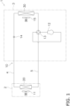
Fig. 1 is a schematic configuration diagram of an air conditioner according to an embodiment of the present disclosure. -
Fig. 2 is a schematic view of an outdoor unit. -
Fig. 3 is a cross-sectional view of first and second flat tubes. -
Fig. 4 is a cross-sectional view of the first and second fins. -
Fig. 5 is a diagram illustrating a method of measuring a potential in an example. -
Fig. 6 is a diagram illustrating the method of measuring the potential in the example. -
Fig. 7 is a diagram illustrating the method of measuring the potential in the example. - An air conditioner 1 according to an embodiment of the present disclosure will be described with reference to
Figs. 1 to 4 . As illustrated inFig. 1 , the air conditioner 1 is used for indoor cooling and heating for a building or the like by performing a vapor compression refrigeration cycle operation. - The air conditioner 1 mainly includes an
indoor unit 2 and anoutdoor unit 3, as well as a liquid-refrigerant connection pipe 4 and a gas-refrigerant connection pipe 5 that connect theindoor unit 2 and theoutdoor unit 3. A vaporcompression refrigerant circuit 10 of the air conditioner 1 is configured by connecting theindoor unit 2 and theoutdoor unit 3 through the liquid-refrigerant connection pipe 4 and the gas-refrigerant connection pipe 5. - The
indoor unit 2 is installed in a room. Theindoor unit 2 mainly includes afirst heat exchanger 20 and a first fan 11. - The
first heat exchanger 20 is a heat exchanger that functions as an evaporator of a refrigerant during the cooling operation and functions as a radiator of the refrigerant during the heating operation. Thefirst heat exchanger 20 has the liquid side connected to the liquid-refrigerant connection pipe 4, and has the gas side connected to the gas-refrigerant connection pipe 5. - The first fan 11 sucks indoor air into the
indoor unit 2, supplies the indoor air to thefirst heat exchanger 20, and then discharges the indoor air to the outside of theindoor unit 2. - The
outdoor unit 3 is installed outdoors. Theoutdoor unit 3 mainly includes acompressor 12, a flowpath switching mechanism 13, asecond heat exchanger 30, and anexpansion mechanism 14. - The
compressor 12 is a mechanism that compresses a low-pressure refrigerant in the refrigeration cycle until the refrigerant reaches a high pressure. - The flow
path switching mechanism 13 is a mechanism that switches the direction of the flow of the refrigerant when switching between the cooling operation and the heating operation. During the cooling operation, the flowpath switching mechanism 13 connects the discharge side of thecompressor 12 to the gas side of thesecond heat exchanger 30, and connects the gas side of thefirst heat exchanger 20 to the suction side of thecompressor 12 through the gas-refrigerant connection pipe 5 (see the solid line of the flowpath switching mechanism 13 inFig. 1 ). During the heating operation, the flowpath switching mechanism 13 connects the discharge side of thecompressor 12 to the gas side of thefirst heat exchanger 20 through the gas-refrigerant connection pipe 5, and connects the gas side of thesecond heat exchanger 30 to the suction side of the compressor 12 (see the broken line of the flowpath switching mechanism 13 inFig. 1 ). - The
second heat exchanger 30 is a heat exchanger that functions as a radiator of the refrigerant during the cooling operation and functions as an evaporator of the refrigerant during the heating operation. Thesecond heat exchanger 30 has the liquid side connected to theexpansion mechanism 14, and has the gas side connected to the flowpath switching mechanism 13. - The
expansion mechanism 14 is a mechanism that decompresses the high-pressure liquid refrigerant that has radiated heat in thesecond heat exchanger 30 before being sent to thefirst heat exchanger 20 during the cooling operation, and decompresses the high-pressure liquid refrigerant that has radiated heat in thefirst heat exchanger 20 before being sent to thesecond heat exchanger 30 during the heating operation. - The
outdoor unit 3 is provided with asecond fan 15 for sucking outdoor air into theoutdoor unit 3, supplying the outdoor air to thesecond heat exchanger 30, and then discharging the outdoor air to the outside of theoutdoor unit 3. - The
first heat exchanger 20 and thesecond heat exchanger 30 will be described with reference toFigs. 2 to 4 . Thefirst heat exchanger 20 and thesecond heat exchanger 30 are micro-channel heat exchangers. - As illustrated in
Fig. 2 , thefirst heat exchanger 20 includes a firstflat tube 21 and afirst fin 22. Here, a plurality of the firstflat tubes 21 and a plurality of thefirst fins 22 are provided. Thefirst fin 22 is joined to the firstflat tube 21. - The
first heat exchanger 20 implements heat exchange between the refrigerant flowing inside the firstflat tubes 21 and the indoor air flowing outside the firstflat tubes 21. With thefirst heat exchanger 20, the indoor air and the refrigerant exchange heat without being mixed with each other. - The material of the first
flat tubes 21 and thefirst fins 22 is not particularly limited, and includes, for example, aluminum, copper, and the like. The firstflat tubes 21 and thefirst fins 22 of the present embodiment are made of aluminum or an aluminum alloy. - The plurality of first
flat tubes 21 are arranged in the vertical direction. The refrigerant flows inside the firstflat tubes 21. As illustrated inFigs. 2 and3 , the firstflat tube 21 is a heat transfer tube having a flat shape. Here, the firstflat tube 21 is a flat perforated tube. In the firstflat tube 21, a plurality of throughholes 211 through which the refrigerant to exchange heat with the indoor air in thefirst heat exchanger 20 passes are formed to be arranged side by side in a predetermined direction. The plurality of throughholes 211 penetrate along the longitudinal direction. - As illustrated in
Fig. 3 , the firstflat tube 21 includes afirst base material 212 and afirst surface layer 213. - The
first surface layer 213 is provided on the surface of the firstflat tube 21. Thefirst surface layer 213 may be provided entirely on the surface of the firstflat tube 21, or may be provided partially on the surface of the first flat tube 21 (not illustrated). In other words, thefirst surface layer 213 may be formed entirely on the exposed outer surface, or may be formed partially on the exposed outer surface (not illustrated). Thefirst surface layer 213 is formed partially in the thickness direction from the outer surface of the firstflat tube 21 toward the inner surface on which the refrigerant flows, and is not formed entirely over the thickness. In other words, in the firstflat tube 21, thefirst surface layer 213 is not formed on at least a part of the inner surface on which the refrigerant flows. In the present embodiment, thefirst surface layer 213 is not formed entirely on the inner surface of the firstflat tube 21. - The
first surface layer 213 is less noble in potential than thefirst base material 212. Therefore, in the firstflat tube 21, thefirst surface layer 213 on the outer surface side is a sacrificial layer that prevents the progress of corrosion of thefirst base material 212 on the inner surface side. - The
first surface layer 213 contains a metal such as zinc in order to lower the potential. Thefirst surface layer 213 of the present embodiment is a zinc diffusion layer in which zinc is thermally sprayed. - As illustrated in
Fig. 2 , thefirst fins 22 are joined to the plurality of firstflat tubes 21. Here, the firstflat tubes 21 and thefirst fins 22 are joined to each other by brazing. Thefirst fins 22 may or may not be in contact with the firstflat tubes 21. Thefirst fins 22 increase the heat transfer area between the firstflat tubes 21 and the indoor air to facilitate the heat exchange between the refrigerant and the indoor air. - The
first fins 22 are stacked in the longitudinal direction in which the firstflat tubes 21 extend. Here, the plurality offirst fins 22 extend in the vertical direction so as to intersect (orthogonally inFig. 2 ) with the firstflat tubes 21. - The
first fin 22 is a flat plate-shaped member. Further, thefirst fin 22 has notches for allowing insertion of the plurality of firstflat tubes 21. These plurality of notches are arranged in the vertical direction. Thefirst fin 22 may have a collar portion. - As illustrated in
Fig. 4 , thefirst fin 22 includes afirst body portion 221 and afirst surface layer 222. - The
first surface layer 222 is provided on the surface of thefirst body portion 221. Here, thefirst surface layer 222 is provided on both surfaces extending in the longitudinal direction of thefirst body portion 221. - The thickness of the
first surface layer 222 is smaller than the thickness of thefirst body portion 221. The thickness of each of thefirst fins 22 is the maximum value of the distance from the outer surface toward the inside. - The
first surface layer 222 is less noble in potential than thefirst body portion 221. Therefore, in thefirst fin 22, thefirst surface layer 222 on the outer surface side is a sacrificial layer that prevents the progress of corrosion of thefirst body portion 221 on the inner surface side. - The
first fin 22 contains a metal such as zinc in order to lower the potential. Thefirst surface layer 222 of the present embodiment is a zinc diffusion layer in which zinc is thermally sprayed. Thefirst fin 22 may further contain magnesium, copper, and the like. - The
first fin 22 may be electrically less noble or more noble than the firstflat tube 21. Specifically, thefirst surface layer 222 of thefirst fin 22 may be electrically less noble or more noble than thefirst surface layer 213 of the firstflat tube 21. In other words, the potential may increase in the order of thefirst surface layer 213 of the firstflat tube 21, thefirst fin 22, and thefirst base material 212 of the firstflat tube 21, or the potential may increase in the order of thefirst fin 22, thefirst surface layer 213 of the firstflat tube 21, and thefirst base material 212 of the firstflat tube 21. Still, thefirst fin 22 is electrically less noble than thefirst base material 212. In the present embodiment, the potential of thefirst fin 22 is higher than the potential of the firstflat tube 21. - The potential of the
first fin 22 of the present embodiment is not less than -890 mV and not more than -750 mV, preferably not less than -890 mV and not more than -800 mV, and more preferably not less than -850 mV and not more than -800 mV. The potential of thefirst fin 22 is the potential of the outermost surface. Therefore, the potential of thefirst fin 22 is the potential of thefirst surface layer 222 when thefirst fin 22 includes thefirst surface layer 222, and is the potential of thefirst body portion 221 when thefirst fin 22 does not include thefirst surface layer 222. - Such a potential of the
first fin 22 is achieved by adjusting the amount of metal such as zinc contained to lower the potential. - In the present embodiment, the potential difference between the
first fin 22 and the firstflat tube 21 is not less than 20 mV and not more than 60 mV. This potential difference is the absolute value of the difference between the potential of the firstflat tube 21 and the potential of thefirst fin 22. Specifically, this potential difference is the absolute value of the difference between the potential of the outer surface of the firstflat tube 21 and the potential of the outer surface of thefirst fin 22. - Such a potential difference is achieved by adjusting the amount of metal such as zinc contained in the
first fins 22 and the firstflat tubes 21 to lower the potential. - Note that the potentials of the first
flat tubes 21 and thefirst fins 22 are values obtained by taking out some of the firstflat tubes 21 and thefirst fins 22 from thefirst heat exchanger 20, producing test pieces, and measuring the test pieces by a three-electrode method. - The
first heat exchanger 20 further includes a brazing material (not illustrated) connecting the firstflat tubes 21 and thefirst fins 22. The brazing material of the present embodiment contains aluminum. - As illustrated in
Fig. 2 , thesecond heat exchanger 30 includes a secondflat tube 31 and asecond fin 32. Here, a plurality of the secondflat tubes 31 and a plurality of thesecond fins 32 are provided. Thesecond fin 32 is joined to the secondflat tube 31. - The
second heat exchanger 30 implements heat exchange between the refrigerant flowing inside the secondflat tubes 31 and the outdoor air flowing outside the secondflat tubes 31. With thesecond heat exchanger 30, the outdoor air and the refrigerant exchange heat without being mixed with each other. - The material of the second
flat tubes 31 and thesecond fins 32 is not particularly limited, and includes, for example, aluminum, copper, and the like. The secondflat tubes 31 and thesecond fins 32 of the present embodiment are made of aluminum or an aluminum alloy. - The plurality of second
flat tubes 31 are arranged in the vertical direction. The refrigerant flows inside the secondflat tubes 31. As illustrated inFigs. 2 and3 , the secondflat tube 31 is a heat transfer tube having a flat shape. Here, the secondflat tube 31 is a flat perforated tube. In the secondflat tube 31, a plurality of throughholes 311 through which the refrigerant to exchange heat with the outdoor air in thesecond heat exchanger 30 passes are formed to be arranged side by side in a predetermined direction. The plurality of throughholes 311 penetrate along the longitudinal direction. - As illustrated in
Fig. 3 , the secondflat tube 31 includes asecond base material 312 and asecond surface layer 313. - The
second surface layer 313 is provided on the surface of the secondflat tube 31. Thesecond surface layer 313 may be provided entirely on the surface of the secondflat tube 31, or may be provided partially on the surface of the second flat tube 31 (not illustrated). In other words, thesecond surface layer 313 may be formed entirely on the exposed outer surface, or may be formed partially on the exposed outer surface (not illustrated). Thesecond surface layer 313 is formed partially in the thickness direction from the outer surface of the secondflat tube 31 toward the inner surface on which the refrigerant flows, and is not formed entirely over the thickness. In other words, in the secondflat tube 31, thesecond surface layer 313 is not formed on at least a part of the inner surface on which the refrigerant flows. In the present embodiment, thesecond surface layer 313 is not formed entirely on the inner surface of the secondflat tube 31. - The
second surface layer 313 is less noble in potential than thesecond base material 312. Therefore, in the secondflat tube 31, thesecond surface layer 313 on the outer surface side is a sacrificial layer that prevents the progress of corrosion of thesecond base material 312 on the inner surface side. - Note that the potentials of the
second base material 312 and thesecond surface layer 313 are values obtained by taking out some of thesecond base materials 312 and the second surface layers 313 from thesecond heat exchanger 30, producing test pieces, and measuring the test pieces by the three-electrode method. - The
second surface layer 313 contains a metal such as zinc in order to lower the potential. Thesecond surface layer 313 of the present embodiment is a zinc diffusion layer in which zinc is thermally sprayed. - As illustrated in
Fig. 2 , thesecond fins 32 are joined to the plurality of secondflat tubes 31. Here, the secondflat tubes 31 and thesecond fins 32 are joined to each other by brazing. Thesecond fins 32 may or may not be in contact with the secondflat tubes 31. Thesecond fins 32 increase the heat transfer area between the secondflat tubes 31 and the indoor air to promote heat exchange between the refrigerant and the indoor air. - The
second fins 32 are stacked in the longitudinal direction in which the secondflat tubes 31 extend. Here, the plurality ofsecond fins 32 extend in the vertical direction so as to intersect (orthogonally inFig. 2 ) with the secondflat tubes 31. - The
second fin 32 is a flat plate-shaped member. Further, thesecond fin 32 has notches for allowing insertion of the plurality of secondflat tubes 31. These plurality of notches are arranged in the vertical direction. Thesecond fin 32 may have a collar portion. - As illustrated in
Fig. 4 , thesecond fin 32 includes asecond body portion 321 and asecond surface layer 322. - The
second surface layer 322 is provided on the surface of thesecond body portion 321. Here, thesecond surface layer 322 is provided on both surfaces extending in the longitudinal direction of thesecond body portion 321. - The thickness of the
second surface layer 322 is smaller than the thickness of thesecond body portion 321. The thickness of each of thesecond fins 32 is the maximum value of the distance from the outer surface toward the inside. - The
second surface layer 322 is less noble in potential than thesecond body portion 321. Therefore, in thesecond fin 32, thesecond surface layer 322 on the outer surface side is a sacrificial layer that prevents the progress of corrosion of thesecond body portion 321 on the inner surface side. - The
second fin 32 contains a metal such as zinc in order to lower the potential. Thesecond surface layer 322 of the present embodiment is a zinc diffusion layer in which zinc is thermally sprayed. Thesecond fin 32 may further contain magnesium, copper, and the like. - The
second fin 32 may be electrically less noble or more noble than the secondflat tube 31. Specifically, thesecond surface layer 322 of thesecond fin 32 may be electrically less noble or more noble than thesecond surface layer 313 of the secondflat tube 31. In other words, the potential may increase in the order of thesecond surface layer 313 of the secondflat tube 31, thesecond fin 32, and thesecond base material 312 of the secondflat tube 31, or the potential may increase in the order of thesecond fin 32, thesecond surface layer 313 of the secondflat tube 31, and thesecond base material 312 of the secondflat tube 31. Still, thesecond fin 32 is electrically less noble than thesecond base material 312. - The potential of the
second fin 32 is a value obtained by taking out some of thesecond fins 32 from thesecond heat exchanger 30, producing test pieces, and measuring the test pieces by the three-electrode method. - The
second heat exchanger 30 further includes a brazing material (not illustrated) connecting the secondflat tubes 31 and thesecond fins 32. The brazing material of the present embodiment contains aluminum. - The potential of the
first fin 22 is higher than the potential of thesecond fin 32, and is preferably not less than 110% of the potential of thesecond fin 32. The potential of thefirst fin 22 is the potential of the outer surface of thefirst fin 22. The potential of thesecond fin 32 is the potential of the outer surface of thesecond fin 32. - Further, the potential difference between the
first fin 22 and the firstflat tube 21 is smaller than the potential difference between thesecond fin 32 and the secondflat tube 31, and is preferably not larger than 90% of the potential difference between thesecond fin 32 and the secondflat tube 31. For example, the potential difference between thefirst fin 22 and the firstflat tube 21 is lower than the potential difference between thesecond fin 32 and the secondflat tube 31 by not less than 20 mV and not more than 60 mV, and preferably by not less than 30 mV and not more than 50 mV. Here, the potential difference between thefirst fin 22 and the firstflat tube 21 is the absolute value of the difference between the potential of the firstflat tube 21 and the potential of thefirst fin 22. The potential difference between thesecond fin 32 and the secondflat tube 31 is the absolute value of the difference between the potential of thesecond fin 32 and the potential of the secondflat tube 31. Specifically, the potential difference between thefirst fin 22 and the firstflat tube 21 is the absolute value of the difference between the potential of the outer surface of the firstflat tube 21 and the potential of the outer surface of thefirst fin 22. The potential difference between thesecond fin 32 and the secondflat tube 31 is the absolute value of the difference between the potential of the outer surface of the secondflat tube 31 and the potential of the outer surface of thesecond fin 32. - Such a potential is achieved by adjusting the amount of metal such as zinc contained in the first
flat tubes 21, thefirst fins 22, the secondflat tubes 31, and thesecond fins 32 in order to lower the potential. - When the air conditioner 1 performs the cooling operation, a low-pressure refrigerant in the refrigeration cycle is sucked into the
compressor 12, compressed to a high pressure in the refrigeration cycle, and then discharged. The high-pressure refrigerant discharged from thecompressor 12 is sent to thesecond heat exchanger 30 through the flowpath switching mechanism 13. The high-pressure refrigerant sent to thesecond heat exchanger 30 exchanges heat with the outdoor air supplied by thesecond fan 15 and radiates heat in thesecond heat exchanger 30. The high-pressure refrigerant having radiated heat in thesecond heat exchanger 30 is sent to theexpansion mechanism 14 and is decompressed to a low pressure in the refrigeration cycle. The low-pressure refrigerant decompressed in theexpansion mechanism 14 is sent to thefirst heat exchanger 20 through the liquid-refrigerant connection pipe 4. The low-pressure refrigerant sent to thefirst heat exchanger 20 exchanges heat with the indoor air supplied by the first fan 11 and evaporates in thefirst heat exchanger 20. As a result, the indoor air is cooled and blown into the room. The low-pressure refrigerant having evaporated in thefirst heat exchanger 20 is sucked into thecompressor 12 again through the gas-refrigerant connection pipe 5 and the flowpath switching mechanism 13. - When the air conditioner 1 performs the heating operation, a low-pressure refrigerant in the refrigeration cycle is sucked into the
compressor 12, compressed to a high pressure in the refrigeration cycle, and then discharged. The high-pressure refrigerant discharged from thecompressor 12 is sent to thefirst heat exchanger 20 through the flowpath switching mechanism 13 and the gas-refrigerant connection pipe 5. The high-pressure refrigerant sent to thefirst heat exchanger 20 exchanges heat with the indoor air supplied by the first fan 11 and radiates heat in thefirst heat exchanger 20. As a result, the indoor air is heated and blown into the room. The high-pressure refrigerant having radiated heat in thefirst heat exchanger 20 is sent to theexpansion mechanism 14 through the liquid-refrigerant connection pipe 4, and is decompressed to a low pressure in the refrigeration cycle. The low-pressure refrigerant decompressed in theexpansion mechanism 14 is sent to thesecond heat exchanger 30. The low-pressure refrigerant sent to thesecond heat exchanger 30 exchanges heat with the outdoor air supplied by thesecond fan 15 and evaporates in thesecond heat exchanger 30. The low-pressure refrigerant having evaporated in thesecond heat exchanger 30 is sucked into thecompressor 12 again through the flowpath switching mechanism 13. - According to a possible technique, in a cross-fin heat exchanger, a resin layer may be formed on a surface of a fin to insulate the fin from a heat transfer tube to suppress corrosion. However, since a fin and a heat transfer tube (flat tube) are brazed in the microchannel heat exchanger, the resin layer cannot be formed on the surface of the fin. Therefore, when there is a potential difference between the fin and the heat transfer tube, the fin or the heat transfer tube corrodes. For example, to prevent corrosion of the heat transfer tube in order to prevent refrigerant leakage, the potential of the fin may be made lower than the potential of the heat transfer tube. In this case, the fin containing aluminum preferentially corrodes to generate aluminum hydroxide. When this microchannel heat exchanger is provided in an indoor unit, there arises the problem that white powdery aluminum hydroxide may scatter into the room. The inventor of the present invention has arrived at the air conditioner 1 of the present disclosure in view of such a problem.
- Specifically, the problem of scattering of powder derived from corrosion is not a big problem with the outdoor unit, but is problematic with the indoor unit, and thus is a problem unique to the indoor unit. On the other hand, there is another problem in that the outdoor unit is more likely to corrode due to a higher abundance of chloride ions in the air than the indoor unit. As a result of intensive studies to solve these problems, the inventor of the present invention has drawn idea from the relationship between the potential of the fin and the flat tube of the indoor unit and the potential of the fin and the flat tube of the outdoor unit.
- Thus, the air conditioner 1 according to the present embodiment includes the
indoor unit 2 and theoutdoor unit 3. Theindoor unit 2 includes thefirst heat exchanger 20. Theoutdoor unit 3 includes thesecond heat exchanger 30. Thefirst heat exchanger 20 includes the firstflat tube 21 and thefirst fin 22. Thefirst fin 22 is joined to the firstflat tube 21. Thesecond heat exchanger 30 includes the secondflat tube 31 and thesecond fin 32. Thesecond fin 32 is joined to the secondflat tube 31. The potential difference between thefirst fin 22 and the firstflat tube 21 is smaller than the potential difference between thesecond fin 32 and the secondflat tube 31. - With the air conditioner 1 of the present embodiment, since the potential difference between the
first fin 22 and the firstflat tube 21 of theindoor unit 2 is made smaller than the potential difference between thesecond fin 32 and the secondflat tube 31 of theoutdoor unit 3, it is possible to effectively suppress corrosion of thefirst fin 22 and the firstflat tube 21 of theindoor unit 2 of the microchannel heat exchanger. Thus, it is possible to further reduce the generation of aluminum hydroxide due to thefirst fin 22 and the firstflat tube 21. Therefore, scattering of the white powdery aluminum hydroxide into the room can be suppressed. - Since the potential difference between the
second fin 32 and the secondflat tube 31 of theoutdoor unit 3 can be made larger than the potential difference between thefirst fin 22 and the firstflat tube 21 of theindoor unit 2, corrosion of thesecond base material 312 of the secondflat tube 31 of theoutdoor unit 3 can be suppressed. - In addition, since the
outdoor unit 3 is more likely to corrode than theindoor unit 2, the potential of thesecond fin 32 of theoutdoor unit 3 is preferably made lower than the potential of the secondflat tube 31. In this way, in order to suppress corrosion of the secondflat tube 31 and prevent refrigerant leakage, a potential design can be adopted in which thesecond fin 32 preferentially corrode. Also in this case, while the generation of the aluminum hydroxide in theoutdoor unit 3 would not be a big problem, by reducing the potential difference between thefirst fin 22 and the firstflat tube 21 of theindoor unit 2, powder scattering from theindoor unit 2 can be suppressed. - (4-2)
In the air conditioner 1 according to the present embodiment, the potential of thefirst fin 22 is higher than the potential of thesecond fin 32. - Here, by making the potential of the
first fin 22 of theindoor unit 2 higher than the potential of thesecond fin 32 of theoutdoor unit 3, the corrosion of thefirst fin 22 is suppressed, and thus the scattering of aluminum hydroxide into the room can be further suppressed. - (4-3)
In the air conditioner 1 according to the present embodiment, the potential of thefirst fin 22 is higher than the potential of the firstflat tube 21. - Here, by making the potential of the
first fin 22 higher than the potential of the firstflat tube 21, it is possible to further suppress scattering of aluminum hydroxide into the room by suppressing corrosion of thefirst fin 22. - (4-4)
In the air conditioner 1 according to the present embodiment, the potential difference between thefirst fin 22 and the firstflat tube 21 is not less than 20 mV and not more than 60 mV. - Here, the potential difference between the
first fin 22 and the firstflat tube 21 of theindoor unit 2 is made as small as not less than 20 mV and not more than 60 mV. Accordingly, it is possible to further reduce the generation of aluminum hydroxide due to corrosion of thefirst fin 22 and the firstflat tube 21. - (4-5)
In the air conditioner 1 according to the present embodiment, the potential of thefirst fin 22 is not less than -890 mV and not more than -750 mV. - Here, the
first fin 22 of thefirst heat exchanger 20 of theindoor unit 2 is designed to be at a high potential that is not less than -890 mV and not more than -750 mV. Thus, it is possible to reduce generation of aluminum hydroxide due to corrosion of thefirst fin 22 without excessively corroding thefirst fin 22. - Further, in the
indoor unit 2 of the present embodiment, excessive corrosion of thefirst fin 22 can be suppressed, and therefore, a corrosive odor can also be suppressed. - (4-6)
In the air conditioner 1 according to the present embodiment, the potential of thefirst fin 22 is not less than -890 mV and not more than -800 mV. - Here, the
first fin 22 of thefirst heat exchanger 20 of theindoor unit 2 is designed to be at a high potential that is not less than -890 mV and not more than -800 mV. Thus, it is possible to further reduce generation of aluminum hydroxide due to corrosion of thefirst fin 22 without excessively corroding thefirst fin 22. - (4-7)
The air conditioner 1 according to the present embodiment performs a cooling operation and a heating operation. - In the present embodiment, excessive corrosion of the
first fin 22 and the firstflat tube 21 can be suppressed even when operation that causes condensation in the evaporator is performed. Therefore, when the air conditioner 1 performs the cooling operation and the heating operation, it is possible to reduce the generation of aluminum hydroxide due to the corrosion of thefirst fin 22 and the firstflat tube 21 of theindoor unit 2. - In the above embodiment, the
first fin 22 has thefirst surface layer 222, and thesecond fin 32 has thesecond surface layer 322, but the present disclosure is not limited to this. At least one of thefirst fin 22 and thesecond fin 32 of the present disclosure may not have a surface layer. - In the above-described embodiment, the first
flat tube 21 has thefirst surface layer 213, and the secondflat tube 31 has thesecond surface layer 313, but the present disclosure is not limited to this. At least one of the firstflat tube 21 and the secondflat tube 31 of the present disclosure may not have a surface layer. - In the above-described embodiment, the
first surface layer 213 of the firstflat tube 21 and thesecond surface layer 313 of the secondflat tube 31 are described to be a diffusion layer in which zinc is thermally sprayed as an example, but the present disclosure is not limited to this. In the present modification, a clad material is used for the base material and the surface layer. - Specifically, the first
flat tube 21 is formed using a clad material in which a metal to be thefirst base material 212 and a metal to be thefirst surface layer 213 are bonded together. The secondflat tube 31 is formed using a clad material in which a metal to be thesecond base material 312 and a metal to be thesecond surface layer 313 are bonded together. - In the above embodiment, the air conditioner 1 performing the cooling operation and the heating operation is described as an example. However, the air conditioner of the present disclosure is not limited to this. The air conditioner of the present disclosure may further perform a dehumidifying operation, or may be dedicated to cooling.
- In the examples, the effect of making the potential difference between the
first fin 22 and the firstflat tube 21 of theindoor unit 2 smaller than the potential difference between thesecond fin 32 and the secondflat tube 31 of theoutdoor unit 3 was investigated. - In Example 1, the air conditioner 1 illustrated in
Fig. 1 including microchannel heat exchangers as thefirst heat exchanger 20 of theindoor unit 2 and thesecond heat exchanger 30 of theoutdoor unit 3 was manufactured. - Specifically, for the first
flat tube 21, zinc was thermally sprayed on the surface of thefirst base material 212 made of aluminum to form thefirst surface layer 213. For thefirst fin 22, zinc was thermally sprayed on the surface of thefirst body portion 221 made of aluminum to form thefirst surface layer 222. The firstflat tube 21 and thefirst fin 22 were joined together using a brazing material containing aluminum to produce thefirst heat exchanger 20. - Further, for the second
flat tube 31, zinc was thermally sprayed on the surface of thesecond base material 312 made of aluminum to form thesecond surface layer 313. For thesecond fin 32, zinc was thermally sprayed on the surface of thesecond body portion 321 made of aluminum to form thesecond surface layer 322. The secondflat tube 31 and thesecond fin 32 were joined together using a brazing material containing aluminum to produce thesecond heat exchanger 30. In Example 1, the zinc content rate of thefirst fin 22 was lower than the zinc content rate of thesecond fin 32. - Comparative Example 1 was basically the same as Example 1, except for the first fin of the first heat exchanger of the indoor unit. Specifically, the zinc content rate of a first fin of an indoor unit of Comparative Example 1 was made to be the same as the zinc content rate of a second fin of an outdoor unit.
- The potentials of the first base material and the first surface layer of the first flat tube, the first surface layer of the first fin, the second base material and the second surface layer of the second flat tube, and the second surface layer of the second fin of Example 1 and Comparative Example 1 were measured. The measurement method is as follows.
- A portion of the first base material and the first surface layer of the first flat tube, the first surface layer of the first fin, the second base material and the second surface layer of the second flat tube, and the second surface layer of the second fin were taken out from the first heat exchanger and the second heat exchanger to produce test pieces, and the test pieces were measured by the three-electrode method. Specifically, as illustrated in
Fig. 5 , the length of the test pieces S was set to 40 mm. Then, as illustrated inFig. 6 , epoxy resin R was attached to the test pieces S, and a test surfaces S1 were exposed. The test surfaces S1 were designed to have the entire circumference length of 10 mm. A 2.67% aluminum chloride aqueous solution was used as a test solution. A saturated calomel electrode was used as a reference electrode. Platinum was used for a counter electrode. As illustrated inFig. 7 , the test pieces S were connected to the counter electrode using a lead wire. Then, the potential of the test surfaces S1 was measured by the three-electrode method in a state of being opened to the atmosphere, at a temperature of 40 °C, and with the pH of the test solution adjusted. - Table 1 below lists the results of the measurement of the potentials of Example 1 and Comparative Example 1.
<Table 1> Indoor unit Outdoor unit First fin First surface layer First base material Second fin Second surface layer Second base material Example 1 -800 mV -830 mV -700 mV -900 mV -830 mV -700 mV Comparative example 1 -900 mV -830 mV -700 mV -900 mV -830 mV -700 mV - As listed in Table 1, in Example 1, the potential (-800 mV) of the first fin was higher than the potential (-900 mv) of the second fin. Further, in Example 1, the potential difference between the first fin and the first flat tube was 30 mV. In Example 1, the potential difference (30 mV) between the first fin and the first flat tube was smaller than the potential difference (70 mV) between the second fin and the second flat tube.
- For the air conditioner of Example 1 and the air conditioner of Comparative Example 1, whether aluminum hydroxide scattered from the indoor unit after the cooling operation and the heating operation were performed was visually confirmed.
- With the air conditioner of Comparative Example 1 in which the potential difference between the
first fin 22 and the firstflat tube 21 of theindoor unit 2 was the same as the potential difference between thesecond fin 32 and the secondflat tube 31 of theoutdoor unit 3, aluminum hydroxide scattered from the indoor unit. On the other hand, with the air conditioner of Example 1 in which the potential difference between thefirst fin 22 and the firstflat tube 21 of theindoor unit 2 was smaller than the potential difference between thesecond fin 32 and the secondflat tube 31 of theoutdoor unit 3, aluminum hydroxide did not scatter from the indoor unit. - From the above, it was confirmed that by making the potential of the
first fin 22 and the firstflat tube 21 of theindoor unit 2 smaller than the potential of thesecond fin 32 and the secondflat tube 31 of theoutdoor unit 3, the generation of aluminum hydroxide due to the corrosion of the first fin and the first flat tube is reduced, and thus the scattering of aluminum hydroxide into the room can be suppressed. Furthermore, it was also confirmed that when the potential of the first fin is high, that is, not less than -890 mV and not more than -750 mV, the generation of aluminum hydroxide due to the corrosion of the first fin was reduced, and thus the scattering of aluminum hydroxide into the room can be suppressed. - While embodiments of the present disclosure have been described above, it should be understood that various changes in mode and detail may be made without departing from the spirit and scope of the present disclosure as set forth in the claims.
-
- 1
- Air conditioner
- 2
- Indoor unit
- 3
- Outdoor unit
- 20
- First heat exchanger
- 21
- First flat tube
- 22
- First fin
- 30
- Second heat exchanger
- 31
- Second flat tube
- 32
- Second fin
- PTL 1:
Japanese Unexamined Patent Application Publication No. 2013-43216
Claims (7)
- An air conditioner (1) comprising:an indoor unit (2) including a first heat exchanger (20); andan outdoor unit (3) including a second heat exchanger (30), whereinthe first heat exchanger includesa first flat tube (21), anda first fin (22) joined to the first flat tube,the second heat exchanger includesa second flat tube (31), anda second fin (32) joined to the second flat tube, anda potential difference between the first fin and the first flat tube is smaller than a potential difference between the second fin and the second flat tube.
- The air conditioner according to claim 1, wherein a potential of the first fin is higher than a potential of the second fin.
- The air conditioner according to claim 1 or 2, wherein a potential of the first fin is higher than a potential of the first flat tube.
- The air conditioner according to any one of claims 1 to 3, wherein the potential difference between the first fin and the first flat tube is not less than 20 mV and not more than 60 mV.
- The air conditioner according to any one of claims 1 to 4, wherein a potential of the first fin is not less than -890 mV and not more than -750 mV.
- The air conditioner according to any one of claims 1 to 5, wherein a potential of the first fin is not less than -890 mV and not more than -800 mV.
- The air conditioner according to any one of claims 1 to 6, wherein a cooling operation and a heating operation are performed.
Priority Applications (1)
| Application Number | Priority Date | Filing Date | Title |
|---|---|---|---|
| EP26158714.1A EP4718012A2 (en) | 2023-03-31 | 2024-03-11 | Air conditioner |
Applications Claiming Priority (2)
| Application Number | Priority Date | Filing Date | Title |
|---|---|---|---|
| JP2023058644 | 2023-03-31 | ||
| PCT/JP2024/009302 WO2024203215A1 (en) | 2023-03-31 | 2024-03-11 | Air conditioner |
Related Child Applications (2)
| Application Number | Title | Priority Date | Filing Date |
|---|---|---|---|
| EP26158714.1A Division EP4718012A2 (en) | 2023-03-31 | 2024-03-11 | Air conditioner |
| EP26158714.1A Division-Into EP4718012A2 (en) | 2023-03-31 | 2024-03-11 | Air conditioner |
Publications (3)
| Publication Number | Publication Date |
|---|---|
| EP4462066A1 true EP4462066A1 (en) | 2024-11-13 |
| EP4462066A4 EP4462066A4 (en) | 2025-03-26 |
| EP4462066B1 EP4462066B1 (en) | 2026-04-29 |
Family
ID=91432736
Family Applications (2)
| Application Number | Title | Priority Date | Filing Date |
|---|---|---|---|
| EP26158714.1A Pending EP4718012A2 (en) | 2023-03-31 | 2024-03-11 | Air conditioner |
| EP24728116.5A Active EP4462066B1 (en) | 2023-03-31 | 2024-03-11 | Air conditioner |
Family Applications Before (1)
| Application Number | Title | Priority Date | Filing Date |
|---|---|---|---|
| EP26158714.1A Pending EP4718012A2 (en) | 2023-03-31 | 2024-03-11 | Air conditioner |
Country Status (5)
| Country | Link |
|---|---|
| US (1) | US20260029136A1 (en) |
| EP (2) | EP4718012A2 (en) |
| JP (2) | JP7513942B1 (en) |
| CN (2) | CN121079563A (en) |
| WO (1) | WO2024203215A1 (en) |
Families Citing this family (1)
| Publication number | Priority date | Publication date | Assignee | Title |
|---|---|---|---|---|
| EP4718012A2 (en) * | 2023-03-31 | 2026-04-01 | Daikin Industries, Ltd. | Air conditioner |
Family Cites Families (10)
| Publication number | Priority date | Publication date | Assignee | Title |
|---|---|---|---|---|
| JP5834624B2 (en) | 2011-08-25 | 2015-12-24 | 日本軽金属株式会社 | Heat exchanger |
| JP2014095524A (en) * | 2012-11-12 | 2014-05-22 | Hitachi Appliances Inc | Air conditioner |
| JP2015117876A (en) | 2013-12-18 | 2015-06-25 | 日本軽金属株式会社 | Fin and tube heat exchanger |
| KR20180113499A (en) * | 2016-02-15 | 2018-10-16 | 가부시키가이샤 유에이씨제이 | heat transmitter |
| KR102282585B1 (en) * | 2016-04-12 | 2021-07-28 | 주식회사 에스피텍 | Corrosion resistant heat exchanger using the control of alloy composition and potential |
| JP2018040513A (en) * | 2016-09-06 | 2018-03-15 | 株式会社デンソー | Heat exchanger tubes and heat exchangers |
| WO2019077744A1 (en) * | 2017-10-20 | 2019-04-25 | 三菱電機株式会社 | Air conditioner |
| KR20220130414A (en) | 2021-03-18 | 2022-09-27 | 삼성전자주식회사 | Heat exchanger and air conditioner including same |
| JP7401803B2 (en) | 2022-03-31 | 2023-12-20 | ダイキン工業株式会社 | air conditioner |
| EP4718012A2 (en) * | 2023-03-31 | 2026-04-01 | Daikin Industries, Ltd. | Air conditioner |
-
2024
- 2024-03-11 EP EP26158714.1A patent/EP4718012A2/en active Pending
- 2024-03-11 CN CN202480023069.8A patent/CN121079563A/en active Pending
- 2024-03-11 EP EP24728116.5A patent/EP4462066B1/en active Active
- 2024-03-11 WO PCT/JP2024/009302 patent/WO2024203215A1/en not_active Ceased
- 2024-03-11 JP JP2024036636A patent/JP7513942B1/en active Active
- 2024-03-28 CN CN202420618903.5U patent/CN222123323U/en active Active
- 2024-06-10 JP JP2024093484A patent/JP2024146948A/en active Pending
-
2025
- 2025-09-30 US US19/346,251 patent/US20260029136A1/en active Pending
Also Published As
| Publication number | Publication date |
|---|---|
| EP4462066A4 (en) | 2025-03-26 |
| JP7513942B1 (en) | 2024-07-10 |
| CN222123323U (en) | 2024-12-06 |
| WO2024203215A1 (en) | 2024-10-03 |
| JP2024146795A (en) | 2024-10-15 |
| EP4718012A2 (en) | 2026-04-01 |
| JP2024146948A (en) | 2024-10-15 |
| US20260029136A1 (en) | 2026-01-29 |
| EP4462066B1 (en) | 2026-04-29 |
| CN121079563A (en) | 2025-12-05 |
Similar Documents
| Publication | Publication Date | Title |
|---|---|---|
| US8708034B2 (en) | Air conditioner | |
| US20260029136A1 (en) | Air conditioner | |
| US12607417B2 (en) | Heat exchanger and air conditioner having same | |
| EP2042825A1 (en) | Fin-and-tube type heat exchanger, and its return bend pipe | |
| US9874402B2 (en) | Heat exchanger, refrigeration cycle apparatus, and method of manufacturing heat exchanger | |
| CN102016482A (en) | Heat exchanger and air conditioner using the same | |
| US11002489B2 (en) | Heat exchanger and air conditioning apparatus | |
| EP3862713A1 (en) | Heat exchanger and air conditioner | |
| CN205156305U (en) | air conditioner | |
| CN119137439B (en) | air conditioner | |
| JPH11304395A (en) | Heat exchanger member and heat exchanger using the same | |
| CN117781516A (en) | heat exchanger | |
| EP3112792A1 (en) | Heat exchanger and air conditioner including the same | |
| JP7727878B1 (en) | air conditioner | |
| US20240230112A1 (en) | Air conditioner indoor unit and air conditioner | |
| CN1325871C (en) | Device for preventing heat exchanger from corrosion of freezer and air conditioner | |
| CN121594696A (en) | High corrosion-resistant aluminum alloy member and heat exchanger using the same | |
| JP2004176178A (en) | Aluminum pipe and method for manufacturing the same | |
| CN1474152A (en) | Device for preventing condenser radiation fin from corrosion using sacrificial anode | |
| KR20250011024A (en) | Heat exchanger and air conditioner including the same | |
| KR20030027371A (en) | Device for preventing corrosion of heat exchanger in refrigerating and air-conditioning machine | |
| KR20240175767A (en) | heat exchanger and fabrication method of the same | |
| JP2001296095A (en) | Heat exchanger and air conditioner equipped with the heat exchanger | |
| CN109813014A (en) | A structure for connecting capillary and copper tube | |
| KR20040051025A (en) | Apparatus for preventing corrosion of air conditioner |
Legal Events
| Date | Code | Title | Description |
|---|---|---|---|
| STAA | Information on the status of an ep patent application or granted ep patent |
Free format text: STATUS: UNKNOWN |
|
| STAA | Information on the status of an ep patent application or granted ep patent |
Free format text: STATUS: THE INTERNATIONAL PUBLICATION HAS BEEN MADE |
|
| PUAI | Public reference made under article 153(3) epc to a published international application that has entered the european phase |
Free format text: ORIGINAL CODE: 0009012 |
|
| STAA | Information on the status of an ep patent application or granted ep patent |
Free format text: STATUS: REQUEST FOR EXAMINATION WAS MADE |
|
| 17P | Request for examination filed |
Effective date: 20240603 |
|
| AK | Designated contracting states |
Kind code of ref document: A1 Designated state(s): AL AT BE BG CH CY CZ DE DK EE ES FI FR GB GR HR HU IE IS IT LI LT LU LV MC ME MK MT NL NO PL PT RO RS SE SI SK SM TR |
|
| P01 | Opt-out of the competence of the unified patent court (upc) registered |
Free format text: CASE NUMBER: APP_1072/2025 Effective date: 20250108 |
|
| A4 | Supplementary search report drawn up and despatched |
Effective date: 20250220 |
|
| RIC1 | Information provided on ipc code assigned before grant |
Ipc: F25B 13/00 20060101ALN20250214BHEP Ipc: F28F 1/32 20060101ALI20250214BHEP Ipc: F28F 21/08 20060101ALI20250214BHEP Ipc: F28D 1/053 20060101ALI20250214BHEP Ipc: F25B 39/00 20060101ALI20250214BHEP Ipc: F24F 1/14 20110101ALI20250214BHEP Ipc: F24F 1/0059 20190101ALI20250214BHEP Ipc: F28F 19/00 20060101AFI20250214BHEP |
|
| GRAP | Despatch of communication of intention to grant a patent |
Free format text: ORIGINAL CODE: EPIDOSNIGR1 |
|
| STAA | Information on the status of an ep patent application or granted ep patent |
Free format text: STATUS: GRANT OF PATENT IS INTENDED |
|
| RIC1 | Information provided on ipc code assigned before grant |
Ipc: F28F 19/00 20060101AFI20251006BHEP Ipc: F24F 1/0059 20190101ALI20251006BHEP Ipc: F24F 1/14 20110101ALI20251006BHEP Ipc: F25B 39/00 20060101ALI20251006BHEP Ipc: F28D 1/053 20060101ALI20251006BHEP Ipc: F28F 21/08 20060101ALI20251006BHEP Ipc: F28F 1/32 20060101ALI20251006BHEP Ipc: F25B 13/00 20060101ALN20251006BHEP |
|
| DAV | Request for validation of the european patent (deleted) | ||
| DAX | Request for extension of the european patent (deleted) | ||
| INTG | Intention to grant announced |
Effective date: 20251015 |
|
| GRAS | Grant fee paid |
Free format text: ORIGINAL CODE: EPIDOSNIGR3 |
|
| GRAA | (expected) grant |
Free format text: ORIGINAL CODE: 0009210 |
|
| STAA | Information on the status of an ep patent application or granted ep patent |
Free format text: STATUS: THE PATENT HAS BEEN GRANTED |
|
| AK | Designated contracting states |
Kind code of ref document: B1 Designated state(s): AL AT BE BG CH CY CZ DE DK EE ES FI FR GB GR HR HU IE IS IT LI LT LU LV MC ME MK MT NL NO PL PT RO RS SE SI SK SM TR |
|
| REG | Reference to a national code |
Ref country code: CH Ref legal event code: F10 Free format text: ST27 STATUS EVENT CODE: U-0-0-F10-F00 (AS PROVIDED BY THE NATIONAL OFFICE) Effective date: 20260429 Ref country code: GB Ref legal event code: FG4D |