EP4462060A1 - Heat exchange structure - Google Patents
Heat exchange structure Download PDFInfo
- Publication number
- EP4462060A1 EP4462060A1 EP22918694.5A EP22918694A EP4462060A1 EP 4462060 A1 EP4462060 A1 EP 4462060A1 EP 22918694 A EP22918694 A EP 22918694A EP 4462060 A1 EP4462060 A1 EP 4462060A1
- Authority
- EP
- European Patent Office
- Prior art keywords
- flow channel
- heat exchange
- path
- fluid
- exchange structure
- Prior art date
- Legal status (The legal status is an assumption and is not a legal conclusion. Google has not performed a legal analysis and makes no representation as to the accuracy of the status listed.)
- Granted
Links
Images




Classifications
-
- F—MECHANICAL ENGINEERING; LIGHTING; HEATING; WEAPONS; BLASTING
- F28—HEAT EXCHANGE IN GENERAL
- F28F—DETAILS OF HEAT-EXCHANGE AND HEAT-TRANSFER APPARATUS, OF GENERAL APPLICATION
- F28F3/00—Plate-like or laminated elements; Assemblies of plate-like or laminated elements
- F28F3/02—Elements or assemblies thereof with means for increasing heat-transfer area, e.g. with fins, with recesses, with corrugations
- F28F3/06—Elements or assemblies thereof with means for increasing heat-transfer area, e.g. with fins, with recesses, with corrugations the means being attachable to the element
-
- B—PERFORMING OPERATIONS; TRANSPORTING
- B01—PHYSICAL OR CHEMICAL PROCESSES OR APPARATUS IN GENERAL
- B01J—CHEMICAL OR PHYSICAL PROCESSES, e.g. CATALYSIS OR COLLOID CHEMISTRY; THEIR RELEVANT APPARATUS
- B01J19/00—Chemical, physical or physico-chemical processes in general; Their relevant apparatus
- B01J19/24—Stationary reactors without moving elements inside
-
- F—MECHANICAL ENGINEERING; LIGHTING; HEATING; WEAPONS; BLASTING
- F28—HEAT EXCHANGE IN GENERAL
- F28D—HEAT-EXCHANGE APPARATUS, NOT PROVIDED FOR IN ANOTHER SUBCLASS, IN WHICH THE HEAT-EXCHANGE MEDIA DO NOT COME INTO DIRECT CONTACT
- F28D9/00—Heat-exchange apparatus having stationary plate-like or laminated conduit assemblies for both heat-exchange media, the media being in contact with different sides of a conduit wall
-
- F—MECHANICAL ENGINEERING; LIGHTING; HEATING; WEAPONS; BLASTING
- F28—HEAT EXCHANGE IN GENERAL
- F28D—HEAT-EXCHANGE APPARATUS, NOT PROVIDED FOR IN ANOTHER SUBCLASS, IN WHICH THE HEAT-EXCHANGE MEDIA DO NOT COME INTO DIRECT CONTACT
- F28D9/00—Heat-exchange apparatus having stationary plate-like or laminated conduit assemblies for both heat-exchange media, the media being in contact with different sides of a conduit wall
- F28D9/0031—Heat-exchange apparatus having stationary plate-like or laminated conduit assemblies for both heat-exchange media, the media being in contact with different sides of a conduit wall the conduits for one heat-exchange medium being formed by paired plates touching each other
- F28D9/0037—Heat-exchange apparatus having stationary plate-like or laminated conduit assemblies for both heat-exchange media, the media being in contact with different sides of a conduit wall the conduits for one heat-exchange medium being formed by paired plates touching each other the conduits for the other heat-exchange medium also being formed by paired plates touching each other
-
- F—MECHANICAL ENGINEERING; LIGHTING; HEATING; WEAPONS; BLASTING
- F28—HEAT EXCHANGE IN GENERAL
- F28F—DETAILS OF HEAT-EXCHANGE AND HEAT-TRANSFER APPARATUS, OF GENERAL APPLICATION
- F28F13/00—Arrangements for modifying heat-transfer, e.g. increasing, decreasing
- F28F13/003—Arrangements for modifying heat-transfer, e.g. increasing, decreasing by using permeable mass, perforated or porous materials
-
- F—MECHANICAL ENGINEERING; LIGHTING; HEATING; WEAPONS; BLASTING
- F28—HEAT EXCHANGE IN GENERAL
- F28F—DETAILS OF HEAT-EXCHANGE AND HEAT-TRANSFER APPARATUS, OF GENERAL APPLICATION
- F28F21/00—Constructions of heat-exchange apparatus characterised by the selection of particular materials
- F28F21/08—Constructions of heat-exchange apparatus characterised by the selection of particular materials of metal
Definitions
- the present disclosure relates to a heat exchange structure for performing heat exchange between two fluids.
- a catalytic reactor of a heat exchange type is equipped with a heat exchange structure for performing heat exchange between two fluids.
- the heat exchange structure has a heat-medium flow channel and a reaction flow channel adjacent to each other.
- the heat-medium fluid flows in the heat-medium flow channel.
- the reaction fluid including the reaction raw material flows in the reaction flow channel.
- the heat-medium flow channel and the reaction flow channel are thermally coupled to each other through a partition wall. Therefore, heat exchange occurs between the heat-medium fluid and the reaction fluid with a temperature difference, and the reaction of the reaction material is promoted.
- a fin structure may be installed in at least one of the heat-medium flow channel and the reaction flow channel.
- the fin structure is called a corrugated fin or a waving fin, etc., and is formed by bending a metal plate.
- the fin structure has fins (sides) that are elongated or curved in the longitudinal direction of the flow channel in which the fin structure is installed.
- Patent Literature 1 discloses a heat transfer promotor as the fin structure.
- Patent Literature 1 JP 2017-140591 A
- a predetermined clearance is provided between the fin structure and the inner peripheral surface of the flow channel.
- the clearance reduces friction between the fin structure and the flow channel and facilitates the insertion of the fin structure into and removal from the flow channel. That is, the clearance is essentially provided for the insertion and removal of the fin structure. However, it is also a space that forms a fluid flow with a low contribution to heat exchange or reaction. Thus, the clearance may be one of the factors that reduce heat transfer performance.
- the present disclosure has been made considering the above situations, and the object is to provide a heat exchange structure capable of improving the workability of installation or removal while suppressing the deterioration of heat transfer performance.
- a heat exchange structure includes: a flow channel thermally coupled with another flow passage stacked to each other in a stacking direction; and a path-configuration portion provided in the flow channel.
- the path-configuration portion includes wall portions forming a path of a main flow of a fluid, and a porous body provided in the path and having permeability to the fluid.
- the wall portions may have permeability to the fluid.
- the permeability of the wall portions may be lower than the permeability of the porous body to the fluid.
- the X, Y, and Z directions are defined as three mutually orthogonal directions.
- the X direction is a width direction of the flow channels (flow passages) 51 and 52, which will be described later, and is also the arrangement direction when flow channels are provided in parallel.
- the Y direction is a stacking direction of the flow channels 51 and 52, and is also the main heat transfer direction between the flow channels.
- the Z direction is a longitudinal direction (extending direction) of each flow channel.
- the path-configuration portions described later are formed separately from the flow channels 51 and 52 and are provided in at least one of the flow channels 51 and 52.
- the path-configuration portions 60 are provided only in the flow channels 51.
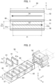
- FIG. 1 is a cross-sectional view of a Y-Z plane of a flow channel in a heat exchange structure according to the first embodiment.
- FIG. 2 is an exploded perspective view of the heat exchange structure.
- the heat exchange structure 50 according to the first embodiment includes at least one flow channel (flow passage) 51 and at least one flow channel (flow passage) 52.
- the flow channel 51 and the flow channel 52 have a length h3 along the Y direction (i.e., height) and a length w3 along the X direction (i.e., width), and extend in the Z direction which is the longitudinal direction.
- the flow channel 51 and the flow channel 52 are stacked along the Y direction (stacking direction).
- the cross-sectional shapes of the flow channel 51 and the flow channel 52 along the Y direction are not limited to the rectangles shown in FIG. 2 .
- the flow channel 51 and the flow channel 52 are provided in parallel and are thermally coupled to each other through a partition wall 55.
- the flow channel 51 may be applied as one of the first flow channel 11 and the second flow channel 21 in the heat exchange section 2 (see FIGs. 10 to 13 ) of the reactor 1 described later.
- the flow channel 52 may be applied as the other flow channel of the first flow channel 11 and the second flow channel 21.
- the flow channel 51 and the flow channel 52 are alternately stacked along the Y direction, and the partition wall 55 between the flow channel 51 and the flow channel 52 corresponds to each of the first partition wall 13 and the second partition wall 23 of the reactor 1.
- the heat exchange structure 50 may include a plurality of flow channels 51 and a plurality of flow channels 52.
- the plurality of flow channels 51 are disposed on a plane parallel to the X-Z plane, and the plurality of flow channels 52 are disposed on another plane parallel to the X-Z plane.
- the longitudinal direction of the flow channel 51 and the longitudinal direction of the flow channel 52 may be parallel to each other and may intersect each other. In other words, the latter may be in a skew relation.
- one of the flow channels 51 and 52 is thermally coupled to the other of the flow channels 51 and 52 through a partition wall 55 in substantially the entire longitudinal direction thereof.
- fluid 53 flows through the flow channel 51 and fluid 54 flows through the flow channel 52.
- the fluid 53 is one of the heat-medium fluid M and the reaction fluid R described later.
- the fluid 54 is the other of the heat-medium fluid M and the reaction fluid R.
- the flow of the fluid 53 and the fluid 54 may be countercurrent or parallel flow.
- the heat transfer area A is constant. Since the fluid 53 and the fluid 54 flow steadily, the change in the temperature difference ⁇ T is small. Therefore, it is found that the increase in amount of heat Q is obtained by increasing the overall heat transfer coefficient U.
- the heat transfer coefficient H1 increases when the main flow of the fluid 53 approaches or enters the temperature boundary layer near the partition wall 55. That is, the heat transfer coefficient H1 increases by deflecting the main flow toward the partition wall 55 or by generating turbulence in the main flow with a component toward the partition wall 55. This tendency is same for the heat transfer coefficient H2, and the heat transfer coefficient H2 increases by controlling the flow of the fluid 54.
- the overall heat transfer coefficient U increases, and finally the heat quantity Q increases. That is, the overall heat transfer coefficient between the two fluids can be improved in a space of limited length. In other words, it is possible to suppress at least the deterioration of heat transfer performance.
- the heat exchange structure 50 includes a path-configuration portion 60.
- the path-configuration portion 60 includes wall portions 61 and a porous body 62.
- the wall portions 61 form a path of a main flow of the fluid 53.
- the porous body 62 is provided in the path.
- the porous body 62 has permeability to the fluid 53.
- the path-configuration portion 60 is configured to be exchangeable with respect to the flow channel 51 by adjusting its size or the like.
- the path formed by the wall portions is not limited to the path formed between the wall portions adjacent to each other, but also includes the path formed between the wall portions and the inner peripheral surface of the flow channel.
- the wall portions 61 and the porous body 62 may be held together by friction between their contact surfaces, and may be joined (integrated) to each other by joining means such as adhesion, brazing or diffusion joining. Otherwise, they may be held integrally by fastening members such as pins or rivets.
- the wall portion 61 has a surface 61a that extends in directions orthogonal to the Z direction (i.e., the X and Y directions).
- the wall portion 61 is formed in a plate-like shape that extends in the X and Y directions.
- the wall portion 61 has a length (i.e., width) w2 along the X direction and a length (i.e., height) h2 along the Y direction.
- the width w2 of the wall portion 61 is smaller than the width w3 of the flow channel 51 and the width w1 of the porous body 62, and the height h2 of the wall portion 61 is equal to the height h1 of the porous body 62.
- the wall portions 61 are arranged at intervals in the Z direction of the flow channel 51 while being displaced in a direction parallel to the extending direction of the surface 61a.
- the wall portions 61 are arranged along the Z direction alternately on one side and the other side of the flow channel 51 in the X direction.
- the wall portions 61 are staggered with intervals along the Z direction.
- the path of the main flow of the fluid 53 is meandered in the X direction.
- the wall portions 61 are inserted into grooves 63 of the porous body 62 having complementary sizes to the wall portions 61.
- the grooves 63 support the wall portions 61 and define the positions of the wall portions 61.
- the wall portion 61 is formed of a plate-like member formed of heat-resistant and heat-conductive material.
- the heat-conductive material is, for example, heat-resistant metal or ceramic.
- the wall portion 61 does not permeability to the fluid 53. Accordingly, the fluid 53 passes through the porous body 62 except for the leakage flow between the flow channel 51 and the path-configuration portion 60. However, as described later, the wall portion 61 may have the permeability.
- the porous body 62 occupies a part other than the wall portion 61 in the structure constituting the path-configuration portion 60.
- the porous body 62 has a large number of voids (vacuoles, or pores) connected with each other. Therefore, the porous body 62 has permeability to the fluid.
- the porous body 62 is, for example, a metal foam body (foamed metal body) formed of an open-celled body (open-cell structure) or a porous sintered body having a large number of communicating holes (through holes).
- the permeability is determined depending on porosity of the porous body 62.
- the Porosity is the ratio of the volume of space occupied within the total volume of a material to the total volume of the material.
- the porous body 62 has a width w1 along the X direction and a height h1 along the Y direction.
- the width w1 of the porous body 62 is equal to the width w3 of the flow channel 51.
- the “equal” means substantially equal. That is, it means having a value that enables the installation of the porous body 62 in the flow channel 51 while minimizing leakage flow between the porous body 62 and the inner peripheral surface (inner peripheral wall) 56 (see FIG. 1 ) of the flow channel 51 as much as possible, and it is not limited to exact matching between the width w1 and the width w3.
- the width w1 may be set to a value larger than the width w3 of the flow channel 51 as long as the porous body 62 can be installed. In this case, the degree of adhesion between the partition wall 55 and the porous body 62 is increased, and the heat transfer performance can be improved.
- the height h1 of the porous body 62 is equal to the height h3 of the flow channel 51.
- the depth d1 of the porous body 62 is appropriately set in accordance with the dimensions and usage of the flow channel 51.
- the depth d1 is set to a value equal to or less than the depth d3 of the flow channel 51.
- the depth d1 of the porous body 62 is substantially equal to the length L of the path-configuration portion 60 in the Z direction.
- the porous body 62 has grooves 63 into which wall portions 61 are inserted.
- the groove 63 has a complementary dimension to the wall portion 61.
- the groove 63 supports the wall portion 61 and defines its position.
- the porous body 62 is formed of a material having heat resistance and capable of supporting a catalyst thereon.
- a material is a heat-resistant alloy which mainly consists of one or a plurality of metals such as Fe (iron), Cr (chromium), Al (aluminum), Y (yttrium), Co (cobalt), Ni (nickel), Mg (magnesium), Ti (titanium), Mo (molybdenum), W (tungsten), Nb (niobium), and Ta (tantalum).
- the porous body 62 may be manufactured by molding a thin-plate structured material made of a heat-resistant alloy such as Fecralloy (registered trademark).
- the material of the porous body 62 may be ceramic.
- porous body 62 When the porous body 62 is formed of a metal foam body, some elasticity may be given to the porous body 62.
- the degree of elasticity can be set by adjusting the material of the metal foam body, porosity, dimensions of the supports (cell edges), etc. In general, metal foam bodies are easier to produce with higher porosity than porous sinters.
- a catalyst may be supported on the porous body 62.
- the catalyst contains, as a main component, an active metal effective for promoting the progress of a chemical reaction.
- the active metal includes, for example, Ni (nickel), Co (cobalt), Fe (iron), Pt (platinum), Ru (ruthenium), Rh (rhodium), Pd (palladium), etc., of which only one kind may be used, and a plurality of kinds may be used in combination as long as they are effective for promoting the reaction.
- the surface area of the porous body 62 is very large compared with that of a corrugated fin having an outer shape of the same size, and the reaction can be promoted.
- FIG. 3 is a view for explaining the flow of the fluid 53 in the path-configuration portion 60 and is a cross-sectional view taken from the Y direction.
- the fluid 53 in the path-configuration portion 60 flows from the upstream side (inlet side) to the downstream side (outlet side) of the flow channel 51 (from the left side to the right side in FIG. 1 ) while being disturbed by the collision with the porous body 62 when passing through the porous body 62.
- the disturbance of the flow of the fluid 53 increases the frequency with which the fluid 53 enters the temperature boundary layer near the partition wall 55, thereby suppressing the deterioration of heat transfer performance.
- Heat transfer is also carried out at the part where the path-configuration portion 60 and the partition wall 55 are in contact with each other. This heat transfer contributes to the improvement of the heat transfer performance described above.
- the wall portion 61 is supported by the porous body 62 by being inserted into the groove 63. That is, since the porous body 62 itself functions as a support member for the wall portion 61, the path-configuration portion 60 does not have a member for supporting the wall portions 61 with each other. Accordingly, friction between the path-configuration portion 60 and the inner peripheral surface 56 (see FIG. 1 ) of the flow channel 51 is reduced compared with the case where such a support member is provided, and installation in the flow channel 51 and removal from the flow channel 51 are facilitated. That is, workability of installation or removal can be improved.
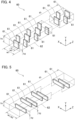
- FIGs. 4, 5 and 6 are views showing the first, second and third modifications of the path-configuration portion 60 according to the present embodiment, respectively.
- the height h2 of the wall portion 61 according to the first modification is equal to the height h1 of the porous body 62.
- the width w2 of the wall portion 61 is smaller than the width w1 of the porous body 62.
- the number of the wall portions 61 along the X direction varies according to the position along the Z direction. For example, as shown in FIG. 4 , one wall portion 61 is arranged at the center of the flow channel 51 in the width direction. Two wall portions 61, 61 are arranged at both ends of the flow channel 51 in the width direction.
- the one wall portion 61 and the two wall portions 61, 61 are alternately arranged along the Z direction. Accordingly, the main flow of the fluid 53 is divided into two flows, and flows in the Z direction while meandering in the X direction so as to repeat merging and separation.
- the width w2 of the wall portion 61 according to the second modification is equal to the width w1 of the porous body 62.
- the height h2 of the wall portion 61 is smaller than the height h1 of the porous body 62.
- the wall portions 61 are alternately arranged along the Z-direction on one side and the other side of the flow channel 51 in the Y-direction. Accordingly, the main flow of the fluid 53 flows in the Z-direction while meandering in the Y-direction.
- the number of the wall portions 61 along the Y direction may change according to the position along the Z direction.
- the wall portions 61 according to the third modification may be formed in a plate-like shape (zonal shape) extending in the Z direction and may be arranged in parallel with each other while being spaced in the X direction.
- the wall portions 61 may be formed in a plate-like shape extending in the Y and Z directions.
- the height h2 of the wall portions 61 is equal to the height h1 of the porous body 62.
- the height h2 of the wall portions 61 may be set to less than half of the height h1 of the porous body 62, and groups of rows of the porous bodies 62 and the wall portions 61 arranged alternately in the X direction may be provided in the Y direction so that the phases of the respective arrangements are shifted in the X direction.
- a second embodiment of the present disclosure will be described below.
- the second embodiment differs from the first embodiment only in the characteristics of the wall portion of the path-configuration portion, and the other configurations of the second embodiment apply those of the first embodiment. Accordingly, the path-configuration portion 60 according to the second embodiment will be described, but the common structure of the first embodiment will be denoted by the same reference numerals and the description thereof will be omitted.
- FIG. 7 is a view for explaining the configuration of the path-configuration portion 60 according to the second embodiment and the flow of fluid therein, and is a cross-sectional view taken from the Y-direction.
- the path-configuration portion 60 includes wall portions 61 and a porous body 62.
- the wall portions 61 form the path of the main flow of the fluid 53.
- the porous body 62 is provided within the path of the main flow of the fluid 53 formed by the wall portion 61.
- the porous body 62 has permeability.
- the wall portions 61 have also permeability to the fluid 53. Therefore, in the second embodiment, the wall portions 61 and the porous body 62, which are the components of the path-configuration portion 60, are both permeable.
- the wall portions 61 are made of the same material as the porous body 62. That is, the wall portion 61 is a metal foam body (foamed metal body) formed of an open-celled body (open-cell structure) or a porous sintered body having a large number of communicating holes (through holes). However, the permeability of the wall portion 61 is lower than that of the porous body 62 to the fluid 53.
- the wall portion 61 of the second embodiment also functions as a wall for deflecting the flow of the main flow of the fluid 53.
- the wall portion 61 has permeability, and its permeability is lower than that of the porous body 62. Accordingly, as shown in FIG. 7 , most of the main flow of the fluid 53 is deflected by the wall portions 61 and flows through the porous body 62. Furthermore, a part of the main flow of the fluid 53 can pass through the wall portions 61. Since the wall portions 61 allows the fluid 53 to pass therethrough, it is possible to reduce a pressure loss compared to a case where a non-permeable wall portions are used.
- the configuration other than the point in that the wall portion 61 is permeable can apply the configuration of the first embodiment. Therefore, the same effect as that obtained in the first embodiment can be obtained in the second embodiment.
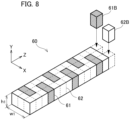
- FIG. 8 is a perspective view showing modifications of the wall portion 61 and the porous body 62.
- the porous body 62 may be formed of an assembly blocks 62B arranged as a path of the main flow of the fluid 53.
- the wall portion 61 may be formed of an assembly of blocks 61B arranged as a wall for the main flow of the fluid 53. Subdivision of the porous body 62 and wall portion 61 provides greater freedom in setting the path of the main flow. In addition, when it is difficult to form a desired path with a single porous member, the path can be formed by laying the blocks.
- the spacing of the wall portions 61 adjacent to each other along the Z direction may be constant or varied.
- the spacing of the wall portions 61 adjacent to each other along the X direction may also be constant or varied. By varying the spacing, it is possible to vary the local overall heat transfer coefficient along the Z or X direction.
- the outer shapes of the blocks 61B and 62B are not limited to rectangular parallelepipeds shown in FIG. 8 .
- the blocks 61B and 62B may be other polyhedra as long as they can stably exist in shape as the path of the main flow or the smallest structural unit constituting the wall portion for the path, and their outer surfaces need not have perfect planes.
- the block 61B of the wall portion 61 or the block 62B of the porous body 62 is formed from metal particles, fine undulations are formed on the outer surface of the block.
- adjacent blocks may form spaces where some of their boundaries come into contact (bond) and other areas are sufficiently larger than the pores in the block.
- the shape of the wall portion 61 is not limited to the shapes shown in FIGs. 2 and 8 .
- the wall portion 61 may have a rod-like shape extending in a predetermined direction (e.g., X direction or Y direction).
- first and second embodiments described above also apply to the materials, dimensions, and relative positional relationships of the wall portion 61 and the porous body 62 in the path-configuration portion 60.
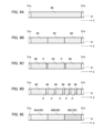
- FIGs. 9A to 9E are side views of a path-configuration portion in a heat exchange structure according to other embodiments.
- the wall portion 61 is omitted in each figure.
- the total length of the path-configuration portion 60 described above is not limited to a value close to the total length of the flow channel 51. That is, it may be continuously disposed from the inlet 51a to the outlet 51b of the flow channel 51 as shown in FIG. 9A . Otherwise, it may be divided into pieces (sections) arranged along the flow channel 51 as shown in FIG. 9B . In the latter case, by dividing the path-configuration portion 60, a deformation of the path-configuration portion 60 such as bending during the installation can be suppressed.
- the divided path-configuration portions 60 may be arranged at intervals along the flow channel 51 (see FIG. 9C ).
- the restriction by the wall portion 61 against the main flow of the fluid 53 in the flow direction is temporarily relaxed within the intervals, thereby reducing the resistance to the flow of the fluid 53.
- the effect of setting these intervals is particularly effective when the continuity of the path of the main flow of the fluid 53 is broken (e.g., when the permeability of the porous body 62 changes in accordance with the position of the porous body 62 (i.e., the position of the path-configuration portion 60 including the porous body 62)).
- the interval P of the divided path-configuration portions 60 or the length L of the divided path-configuration portions 60 may vary stepwise along the flow channel 51.
- the density (i.e., the total length of the path-configuration portion 60 per unit length) of the path-configuration portion 60 in the flow channel 51 may be adjusted for each location. Accordingly, in the flow channel 51, it is possible to adjust the heat transfer area and the heat transfer performance by the path-configuration portion 60.
- the permeability of the porous body 62 may change stepwise according to its position on the flow channel 51.
- the permeability of the porous body 62 of the path-configuration portion 60B may be smaller than that of the porous body 62 of the path-configuration portion 60A
- the permeability of the porous body 62 of the path-configuration portion 60C may be set smaller than that of the porous body 62 of the path-configuration portion 60B.
- the heat transfer coefficient H1 is increased by increasing the frequency with which the main flow of the fluid 53 flows into the vicinity of the partition wall 55. This tendency is same for the heat transfer coefficient H2.
- the flow channel length of the fluid increases, and the frequency of the flow of the main flow of the fluid into the temperature boundary layer near the partition wall 55 increases. Therefore, the heat transfer between the fluid and the partition wall 55 is promoted. Since at least one of the heat transfer coefficient H1 and the heat transfer coefficient H2 increases, the overall heat transfer coefficient U increases, and the heat quantity Q eventually increases. That is, it is possible to improve the overall heat transfer coefficient between the two fluids in a space of limited length. In other words, at least, it is possible to suppress the reduction of heat transfer performance.
- the reactor 1 includes a heat exchange section 2 as the heat exchange structure 50.
- first heat transfer bodies 10 and second heat transfer bodies 20 are stacked in the Y direction, and flow channels (hereinafter, referred to as first flow channels) 11 and second flow channels (hereinafter, referred to as second flow channels) 21 extend in the Z direction.
- first flow channels 11 and second flow channels 21 extend in the Z direction.
- second flow channels 21 extend in the Z direction.
- the width direction of each channel is taken as the X direction described above.
- the X direction is also the alignment direction when multiple first flow channels 11 (second flow channels 21) are provided in parallel.
- FIG. 10 is a side view illustrating the reactor (catalytic reactor) 1 including the heat exchange structure 50 according to the present embodiment.
- FIG. 11 is a cross-sectional view taken along the line XI-XI in FIG. 10 .
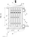
- FIG. 12 is a cross-sectional view taken along the line XII-XII in FIG. 10 .
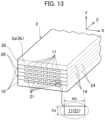
- FIG. 13 is a three-dimensional view with a cross section illustrating a part of the heat exchange section 2 as the heat exchange structure 50.
- the reactor 1 heats or cools the reaction fluid R containing a reactive raw material to progress (promote) the reaction of the reaction fluid R.
- the reactor 1 includes the heat exchange section 2 as the heat exchange structure 50 (see FIG. 1 ) that exchanges (transfers) heat between the heat medium M and the reaction fluid R.
- the heat exchange section 2 includes the first heat transfer bodies 10, the second heat transfer bodies 20, and a lid plate 30.
- the first heat transfer body 10, the second heat transfer body 20 and the lid plate 30 are plate members formed of heat-resistant and thermally conductive materials. They have sufficient thickness to withstand a high internal pressure generated while the reaction fluid R flows.
- the first heat transfer body 10 includes the first flow channels 11 through which the heat medium M flows.
- the second heat transfer body 20 includes the second flow channels 21 through which the reaction fluid R flows.
- the first heat transfer bodies 10 and the second heat transfer bodies 20 are stacked alternately in the Y direction (i.e., the stacking direction).
- the lid plate 30 is set on the top of them.
- the first flow channels 11 and the second flow channels 21 are adjacent to each other thorough a first partition wall 13 or a second partition wall 23 (see FIG. 13 ).
- the first flow channels 11 and the second flow channels 21 are stacked in a non-contact state in the stacking direction of the first heat transfer bodies 10 and the second heat transfer bodies 20.
- the first heat transfer body 10 and the second heat transfer body 20 are formed of a thermally conductive material. Therefore, the first flow channel 11 and the second flow channel 21 are thermally coupled to each other.
- the heat exchange section 2 has a counter-flow type structure in which the reaction fluid R and the heat medium M flow in opposite directions.
- the path-configuration portion 60 described above is detachably installed in the first flow channels 11, the second flow channels 21, or both.
- the path-configuration portion 60 on which a catalyst is supported may be detachably installed in the second flow channel 21 through which the reaction fluid R flows.
- the heat exchange section 2 is formed of at least one set of the first heat transfer body 10 and the second heat transfer body 20.
- the number of each heat transfer body may also be increased to improve the heat exchange performance.
- the number of channels formed in each heat transfer body is set depending on the design conditions of the heat exchange section 2, heat transfer efficiency, etc.
- a housing or insulation material may cover the heat exchange section 2 to reduce heat loss due to heat dissipation from the heat exchange section 2.
- Both ends of the heat exchange section 2, which is a laminated body, are held by fixing members 32, 33.
- a heat medium introduction section 34 is attached to the fixing member 32.
- the heat medium introduction section 34 is a concavely curved lid and forms a space S1 between the section 34 and the heat exchange section 2.
- First inlet ports 12 of the first flow channels 11 are opened toward the space S1 (see FIG. 10 ).
- the first inlet ports 12 are opened on the side surface (end face) 2a of the heat exchange section 2 facing the heat medium introduction section 34.
- the heat medium introduction section 34 has a first introduction tube 36 to introduce the heat medium M.
- the heat medium M flows into each first flow channel 11 through the first introduction tube 36.
- the heat medium introduction section 34 is detachably or openably set on the fixing member 32. By this attachment and detachment, for example, the operator can insert and remove the path-configuration portion 60 from the first flow channels 11.
- the heat medium discharge section 41 is a box-shaped member having one opened face.
- the heat medium discharge section 41 is attached to the heat exchange section 2 so that the opened face faces the first discharge ports 18 of the first heat transfer bodies 10.
- the heat medium discharge section 41 includes a first discharge pipe 42.
- the first discharge pipe 42 discharges the heat medium M that has passed through the heat exchange section 2.
- a reaction fluid introduction section 35 is attached to the fixing member 33.
- the reaction fluid introduction section 35 is a concavely curved lid and forms a space S2 between the section 35 and the heat exchange section 2.
- Second inlet ports 22 of the second flow channels 21 are opened toward the space S2 (see FIG. 10 ).
- the second inlet ports 22 are opened on the side surface (end face) 2b of the heat exchange section 2 facing the reaction fluid introduction section 35.
- the reaction fluid introduction section 35 has a second introduction tube 37 to introduce the reaction fluid R. The reaction fluid R flows into each second flow channel 21 through the second introduction tube 37.
- the reaction fluid introduction section 35 is detachably or openably set on the fixing member 33. By this attachment and detachment, for example, the operator can insert and remove the path-configuration portion 60 from the second flow channels 21.
- the product discharge section 43 is a box-shaped member having one opened face.
- the product discharge section 43 is attached to the heat exchange section 2 so that the opened face faces the second discharge port 28 of the second heat transfer body 20.
- the product discharge section 43 includes a second discharge pipe 44.
- the second discharge pipe 44 discharges the reaction gas G containing products derived from the reaction fluid R.
- the first heat transfer body 10 includes multiple first flow channels 11.
- the first flow channels 11 extend in the Z direction and are arranged in the X direction (the width direction).
- the first flow channels 11 supply the heat of the heat medium M to the first heat transfer body 10.
- the first flow channels 11 are grooves formed on one surface (e.g., the upper surface in the present embodiment) of the first heat transfer body 10.
- Each groove has a rectangular cross section having a width w3 and a height h3 (see FIG. 13 ) and extends in one direction with a length of a depth d3 (see FIG. 11 ).
- the width w3 has a value greater than or equal to the width w1 of the porous body 62.
- the height h3 also has a value greater than or equal to the height h1 of the porous body 62.
- the depth d3 is greater than the depth d1 of the porous body 62.
- the first flow channels 11 linearly extend from the first inlet port 12 located on the side of the fixing member 32 toward the fixing member 33. As shown in FIG. 11 , the multiple first flow channels 11 are disposed in parallel. The first flow channels 11 may be different in the width, height and length.
- the first heat transfer body 10 includes a first partition wall 13, two first sidewalls 14, multiple first intermediate walls 15, and a first end wall 16.
- the first sidewall 14, the first intermediate walls 15 and the first end wall 16 are provided on one side of the first partition wall 13. That is, they are provided on the same surface as the surface on which the first sidewall 14, etc. is provided for the first partition wall 13.
- the first partition wall 13 is a rectangular wall and defines the overall shape of the first heat transfer body 10.
- the first sidewalls 14 are wall parts provided on both sides of the extending direction of the first flow channels 11.
- the first intermediate walls 15 are located between the two first sidewalls 14 and are wall parts provided in parallel with each first sidewall 14.
- the first end wall 16 is provided on the opposite side of the first inlet ports 12 across the first flow channels 11.
- the first end wall 16 is a wall extending in the alignment direction of the first flow channels 11. The first end wall 16 blocks the inflow of the heat medium M toward the space S2.
- the first heat transfer body 10 includes a first connection flow channel 17 extending along the first end wall 16.
- the first connection flow channel 17 is connected with all the first flow channels 11 and the first discharge port 18.
- the second heat transfer body 20 includes multiple second flow channels 21 including reaction regions.
- the middle section of the second flow channel 21 is the main reaction region.
- the second flow channels 21 extend in the Z direction and are arranged in the X direction (the width direction).
- the second flow channel 21 receives the heat of the heat medium M flowing through the first flow channel 11 in the first heat transfer body 10 to react the reaction fluid R to produce the reaction gas G containing the products derived from the reaction fluid R.
- the second flow channels 21 are grooves formed on one surface (the upper surface in the present embodiment) of the second heat transfer body 20. Each groove has a rectangular cross section having a width w3 and a height h3 (see FIG. 13 ) and extends in one direction with a length of a depth d3 (see FIG. 12 ).
- the second flow channels 21 linearly extend from the second inlet port 22 located on the side of the fixing member 33 toward the fixing member 32. As shown in FIG. 12 , the multiple second flow channels 21 are disposed in parallel.
- the second heat transfer body 20 includes a second partition wall 23, two second sidewalls 24, multiple second intermediate walls 25, and a second end wall 26.
- the second sidewall 24, the second intermediate walls 25 and the second end wall 26 are provided on one side of the second partition wall 23.
- the second partition wall 23 is a rectangular wall and defines the overall shape of the second heat transfer body 20.
- the second sidewalls 24 are wall parts provided on both sides of the extending direction of the second flow channels 21.
- the second intermediate walls 25 are located between the two second sidewalls 24 and are wall parts provided in parallel with each second sidewall 24.
- the second end wall 26 is provided on the opposite side of the second inlet ports 22 across the second flow channel 21.
- the second end wall 26 is a wall extending in the alignment direction of the second flow channels 21.
- the second end wall 26 blocks the inflow of the reaction gas G toward the space S1.
- the second heat transfer body 20 includes a second connection flow channel 27 extending along the second end wall 26.
- the second connection flow channel 27 is connected with all the second flow channels 21 and the second discharge port 28.
- the second connection flow channel 27 is a fluid channel, and there is no substantial difference between the two.
- the heat exchange section 2 can be used as any of a liquid-liquid heat exchanger, a gas-gas heat exchanger and a gas-liquid heat exchanger.
- the reaction fluid R may be any of a gas and a liquid.
- the heat medium M may be any of a gas and a liquid.
- the reactor 1 of the present embodiment enables chemical synthesis through various thermal reactions such as endothermic and exothermic reactions. Examples of such syntheses by thermal reactions include endothermic reactions such as the steam reforming reaction of methane represented by formula (3), the dry reforming reaction of methane represented by formula (4), the shift reaction represented by formula (5), the methanation reaction represented by formula (6), and the Fischer Tropsch synthesis reaction represented by formula (7).
- reaction fluid R in these reactions is a gas.
- the heat medium M is a substance that does not corrode the components of the reactor 1.
- gaseous materials such as a combustion gas and a heated air can be used.
- the heat medium M may be a liquid substance such as water or oil, for example.
Landscapes
- Engineering & Computer Science (AREA)
- Physics & Mathematics (AREA)
- Thermal Sciences (AREA)
- Mechanical Engineering (AREA)
- General Engineering & Computer Science (AREA)
- Chemical & Material Sciences (AREA)
- Dispersion Chemistry (AREA)
- Organic Chemistry (AREA)
- Chemical Kinetics & Catalysis (AREA)
- Physical Or Chemical Processes And Apparatus (AREA)
Abstract
Description
- The present disclosure relates to a heat exchange structure for performing heat exchange between two fluids.
- A catalytic reactor of a heat exchange type is equipped with a heat exchange structure for performing heat exchange between two fluids. The heat exchange structure has a heat-medium flow channel and a reaction flow channel adjacent to each other. The heat-medium fluid flows in the heat-medium flow channel. The reaction fluid including the reaction raw material flows in the reaction flow channel. The heat-medium flow channel and the reaction flow channel are thermally coupled to each other through a partition wall. Therefore, heat exchange occurs between the heat-medium fluid and the reaction fluid with a temperature difference, and the reaction of the reaction material is promoted.
- In order to improve the overall heat transfer coefficient between the heat-medium fluid and the reaction fluid, a fin structure may be installed in at least one of the heat-medium flow channel and the reaction flow channel. The fin structure is called a corrugated fin or a waving fin, etc., and is formed by bending a metal plate. The fin structure has fins (sides) that are elongated or curved in the longitudinal direction of the flow channel in which the fin structure is installed. In this regard,
Patent Literature 1 discloses a heat transfer promotor as the fin structure. When the fin structure described above is installed in a reaction flow channel, a catalyst may be supported on the fin structure. - Patent Literature 1:
JP 2017-140591 A - To facilitate the attachment of the fin structure to the flow channel, a predetermined clearance (gap) is provided between the fin structure and the inner peripheral surface of the flow channel. The clearance reduces friction between the fin structure and the flow channel and facilitates the insertion of the fin structure into and removal from the flow channel. That is, the clearance is essentially provided for the insertion and removal of the fin structure. However, it is also a space that forms a fluid flow with a low contribution to heat exchange or reaction. Thus, the clearance may be one of the factors that reduce heat transfer performance.
- The present disclosure has been made considering the above situations, and the object is to provide a heat exchange structure capable of improving the workability of installation or removal while suppressing the deterioration of heat transfer performance.
- A heat exchange structure according to the present disclosure includes: a flow channel thermally coupled with another flow passage stacked to each other in a stacking direction; and a path-configuration portion provided in the flow channel. The path-configuration portion includes wall portions forming a path of a main flow of a fluid, and a porous body provided in the path and having permeability to the fluid.
- The wall portions may have permeability to the fluid. In this case, the permeability of the wall portions may be lower than the permeability of the porous body to the fluid.
- According to the present disclosure, it is possible to provide a heat exchange structure capable of improving the workability of installation or removal while suppressing deterioration of heat transfer performance.
-
-
FIG. 1 is a cross-sectional view of a Y-Z plane of a flow channel in a heat exchange structure according to a first embodiment of the present disclosure. -
FIG. 2 is an exploded perspective view of the heat exchange structure. -
FIG. 3 is a view for explaining the flow of fluid in the path-configuration portion according to the first embodiment and is a cross-sectional view taken from the Y direction. -
FIG. 4 is a view showing a first modification of the path-configuration portion according to the first embodiment. -
FIG. 5 is a view showing a second modification of the path-configuration portion according to the first embodiment. -
FIG. 6 is a view showing a third modification of the path-configuration portion according to the first embodiment. -
FIG. 7 is a view for explaining the configuration of the path-configuration portion according to the second embodiment and the flow of fluid therein, and is a cross-sectional view taken from the Y-direction. -
FIG. 8 is a perspective view showing modifications of the wall portion and the porous body. -
FIG. 9A is a side view of a path-configuration portion in a heat exchange structure according to another embodiment. -
FIG. 9B is a side view of a path-configuration portion in a heat exchange structure according to another embodiment. -
FIG. 9C is a side view of a path-configuration portion in a heat exchange structure according to another embodiment. -
FIG. 9D is a side view of a path-configuration portion in a heat exchange structure according to another embodiment. -
FIG. 9E is a side view of a path-configuration portion in a heat exchange structure according to another embodiment. -
FIG. 10 is a side view showing a reaction device with a heat exchange structure according to each embodiment of the present disclosure. -
FIG. 11 is a cross-sectional view of XI-XI inFIG. 10 . -
FIG. 12 is a cross-sectional view of XII-XII inFIG. 10 . -
FIG. 13 is a three-dimensional cross-sectional view showing a part of a heat exchange section as a heat exchange structure in a reactor. - Hereinafter,
heat exchange structures 50 according to some exemplary embodiments will be described with reference to the drawings. It should be noted that the same reference numerals are used for common parts in the drawings, and descriptions to be duplicated will be omitted. For convenience of explanation, the X, Y, and Z directions are defined as three mutually orthogonal directions. The X direction is a width direction of the flow channels (flow passages) 51 and 52, which will be described later, and is also the arrangement direction when flow channels are provided in parallel. The Y direction is a stacking direction of theflow channels flow channels flow channels configuration portions 60 are provided only in theflow channels 51. - A first embodiment of the present disclosure will be described below.
FIG. 1 is a cross-sectional view of a Y-Z plane of a flow channel in a heat exchange structure according to the first embodiment.FIG. 2 is an exploded perspective view of the heat exchange structure. As shown inFIG. 1 , theheat exchange structure 50 according to the first embodiment includes at least one flow channel (flow passage) 51 and at least one flow channel (flow passage) 52. As shown inFIG. 2 , theflow channel 51 and theflow channel 52 have a length h3 along the Y direction (i.e., height) and a length w3 along the X direction (i.e., width), and extend in the Z direction which is the longitudinal direction. Theflow channel 51 and theflow channel 52 are stacked along the Y direction (stacking direction). The cross-sectional shapes of theflow channel 51 and theflow channel 52 along the Y direction are not limited to the rectangles shown inFIG. 2 . - The
flow channel 51 and theflow channel 52 are provided in parallel and are thermally coupled to each other through apartition wall 55. Theflow channel 51 may be applied as one of thefirst flow channel 11 and thesecond flow channel 21 in the heat exchange section 2 (seeFIGs. 10 to 13 ) of thereactor 1 described later. Theflow channel 52 may be applied as the other flow channel of thefirst flow channel 11 and thesecond flow channel 21. In this case, theflow channel 51 and theflow channel 52 are alternately stacked along the Y direction, and thepartition wall 55 between theflow channel 51 and theflow channel 52 corresponds to each of thefirst partition wall 13 and thesecond partition wall 23 of thereactor 1. - The
heat exchange structure 50 may include a plurality offlow channels 51 and a plurality offlow channels 52. For example, the plurality offlow channels 51 are disposed on a plane parallel to the X-Z plane, and the plurality offlow channels 52 are disposed on another plane parallel to the X-Z plane. In this case, the longitudinal direction of theflow channel 51 and the longitudinal direction of theflow channel 52 may be parallel to each other and may intersect each other. In other words, the latter may be in a skew relation. In either case, one of theflow channels flow channels partition wall 55 in substantially the entire longitudinal direction thereof. - As shown in
FIG. 1 ,fluid 53 flows through theflow channel 51 andfluid 54 flows through theflow channel 52. The fluid 53 is one of the heat-medium fluid M and the reaction fluid R described later. The fluid 54 is the other of the heat-medium fluid M and the reaction fluid R. The flow of the fluid 53 and the fluid 54 may be countercurrent or parallel flow. - There is a temperature difference ΔT, between
fluid 53 andfluid 54. Therefore, when fluid 53 flows throughflow channel 51 andfluid 54 flows throughflow channel 52, heat is transferred between the fluid 53 and the fluid 54. Specifically, the heat is transferred between the fluid 53 and the fluid 54 due to convection between the fluid 53 and thepartition 55, thermal conduction within thepartition 55, and convection between thepartition 55 and the fluid 54. - In this case, the amount of heat Q per unit time is proportional to the product of the overall heat transfer coefficient (heat transfer rate) U, the heat transfer area A of the
partition 55, and the temperature difference ΔT between the fluid 53 and the fluid 54. That is, the relationship among these values is expressed by the following formula (1):
- Here, the heat transfer area A is constant. Since the fluid 53 and the fluid 54 flow steadily, the change in the temperature difference ΔT is small. Therefore, it is found that the increase in amount of heat Q is obtained by increasing the overall heat transfer coefficient U.
- There is also the following relationship among the overall heat transfer coefficient U, the heat transfer coefficient H1 between the fluid 53 and the
partition 55, the heat transfer coefficient H2 between thepartition 55 and the fluid 54, and the thermal conductivity K of thepartition 55.
partition 55. - From the formula (2), it is found that the overall heat transfer coefficient U increases when at least one of the heat transfer coefficients H1 and H2 increases.
- The heat transfer coefficient H1 increases when the main flow of the fluid 53 approaches or enters the temperature boundary layer near the
partition wall 55. That is, the heat transfer coefficient H1 increases by deflecting the main flow toward thepartition wall 55 or by generating turbulence in the main flow with a component toward thepartition wall 55. This tendency is same for the heat transfer coefficient H2, and the heat transfer coefficient H2 increases by controlling the flow of the fluid 54. By increasing at least one of the heat transfer coefficient H1 and the heat transfer coefficient H2, the overall heat transfer coefficient U increases, and finally the heat quantity Q increases. That is, the overall heat transfer coefficient between the two fluids can be improved in a space of limited length. In other words, it is possible to suppress at least the deterioration of heat transfer performance. - Next, a path-configuration portion according to the present embodiment will be described. The
heat exchange structure 50 includes a path-configuration portion 60. The path-configuration portion 60 includeswall portions 61 and aporous body 62. Thewall portions 61 form a path of a main flow of the fluid 53. Theporous body 62 is provided in the path. Theporous body 62 has permeability to thefluid 53. The path-configuration portion 60 is configured to be exchangeable with respect to theflow channel 51 by adjusting its size or the like. The path formed by the wall portions is not limited to the path formed between the wall portions adjacent to each other, but also includes the path formed between the wall portions and the inner peripheral surface of the flow channel. Thewall portions 61 and theporous body 62 may be held together by friction between their contact surfaces, and may be joined (integrated) to each other by joining means such as adhesion, brazing or diffusion joining. Otherwise, they may be held integrally by fastening members such as pins or rivets. - The
wall portion 61 has asurface 61a that extends in directions orthogonal to the Z direction (i.e., the X and Y directions). For example, as shown inFIG. 2 , thewall portion 61 is formed in a plate-like shape that extends in the X and Y directions. Thewall portion 61 has a length (i.e., width) w2 along the X direction and a length (i.e., height) h2 along the Y direction. The width w2 of thewall portion 61 is smaller than the width w3 of theflow channel 51 and the width w1 of theporous body 62, and the height h2 of thewall portion 61 is equal to the height h1 of theporous body 62. - The
wall portions 61 are arranged at intervals in the Z direction of theflow channel 51 while being displaced in a direction parallel to the extending direction of thesurface 61a. For example, as shown inFIG. 2 , thewall portions 61 are arranged along the Z direction alternately on one side and the other side of theflow channel 51 in the X direction. In other words, thewall portions 61 are staggered with intervals along the Z direction. With this arrangement, the path of the main flow of the fluid 53 is meandered in the X direction. Thewall portions 61 are inserted intogrooves 63 of theporous body 62 having complementary sizes to thewall portions 61. Thegrooves 63 support thewall portions 61 and define the positions of thewall portions 61. - The
wall portion 61 is formed of a plate-like member formed of heat-resistant and heat-conductive material. The heat-conductive material is, for example, heat-resistant metal or ceramic. Further, thewall portion 61 does not permeability to thefluid 53. Accordingly, the fluid 53 passes through theporous body 62 except for the leakage flow between theflow channel 51 and the path-configuration portion 60. However, as described later, thewall portion 61 may have the permeability. - The
porous body 62 occupies a part other than thewall portion 61 in the structure constituting the path-configuration portion 60. Theporous body 62 has a large number of voids (vacuoles, or pores) connected with each other. Therefore, theporous body 62 has permeability to the fluid. Theporous body 62 is, for example, a metal foam body (foamed metal body) formed of an open-celled body (open-cell structure) or a porous sintered body having a large number of communicating holes (through holes). When theporous body 62 is a metal foam body, the permeability is determined depending on porosity of theporous body 62. The Porosity is the ratio of the volume of space occupied within the total volume of a material to the total volume of the material. - As shown in
FIG. 2 , theporous body 62 has a width w1 along the X direction and a height h1 along the Y direction. The width w1 of theporous body 62 is equal to the width w3 of theflow channel 51. The "equal" means substantially equal. That is, it means having a value that enables the installation of theporous body 62 in theflow channel 51 while minimizing leakage flow between theporous body 62 and the inner peripheral surface (inner peripheral wall) 56 (seeFIG. 1 ) of theflow channel 51 as much as possible, and it is not limited to exact matching between the width w1 and the width w3. For example, when considering the elasticity of theporous body 62, the width w1 may be set to a value larger than the width w3 of theflow channel 51 as long as theporous body 62 can be installed. In this case, the degree of adhesion between thepartition wall 55 and theporous body 62 is increased, and the heat transfer performance can be improved. - Similarly to the width w1, the height h1 of the
porous body 62 is equal to the height h3 of theflow channel 51. The depth d1 of theporous body 62 is appropriately set in accordance with the dimensions and usage of theflow channel 51. For example, the depth d1 is set to a value equal to or less than the depth d3 of theflow channel 51. Note that the depth d1 of theporous body 62 is substantially equal to the length L of the path-configuration portion 60 in the Z direction. - The
porous body 62 hasgrooves 63 into whichwall portions 61 are inserted. Thegroove 63 has a complementary dimension to thewall portion 61. Thegroove 63 supports thewall portion 61 and defines its position. - The
porous body 62 is formed of a material having heat resistance and capable of supporting a catalyst thereon. Such a material is a heat-resistant alloy which mainly consists of one or a plurality of metals such as Fe (iron), Cr (chromium), Al (aluminum), Y (yttrium), Co (cobalt), Ni (nickel), Mg (magnesium), Ti (titanium), Mo (molybdenum), W (tungsten), Nb (niobium), and Ta (tantalum). For example, theporous body 62 may be manufactured by molding a thin-plate structured material made of a heat-resistant alloy such as Fecralloy (registered trademark). Alternatively, the material of theporous body 62 may be ceramic. - When the
porous body 62 is formed of a metal foam body, some elasticity may be given to theporous body 62. The degree of elasticity can be set by adjusting the material of the metal foam body, porosity, dimensions of the supports (cell edges), etc. In general, metal foam bodies are easier to produce with higher porosity than porous sinters. - A catalyst may be supported on the
porous body 62. In this case, the catalyst contains, as a main component, an active metal effective for promoting the progress of a chemical reaction. The active metal includes, for example, Ni (nickel), Co (cobalt), Fe (iron), Pt (platinum), Ru (ruthenium), Rh (rhodium), Pd (palladium), etc., of which only one kind may be used, and a plurality of kinds may be used in combination as long as they are effective for promoting the reaction. The surface area of theporous body 62 is very large compared with that of a corrugated fin having an outer shape of the same size, and the reaction can be promoted. -
FIG. 3 is a view for explaining the flow of the fluid 53 in the path-configuration portion 60 and is a cross-sectional view taken from the Y direction. The fluid 53 in the path-configuration portion 60 flows from the upstream side (inlet side) to the downstream side (outlet side) of the flow channel 51 (from the left side to the right side inFIG. 1 ) while being disturbed by the collision with theporous body 62 when passing through theporous body 62. The disturbance of the flow of the fluid 53 increases the frequency with which the fluid 53 enters the temperature boundary layer near thepartition wall 55, thereby suppressing the deterioration of heat transfer performance. Heat transfer is also carried out at the part where the path-configuration portion 60 and thepartition wall 55 are in contact with each other. This heat transfer contributes to the improvement of the heat transfer performance described above. - The
wall portion 61 is supported by theporous body 62 by being inserted into thegroove 63. That is, since theporous body 62 itself functions as a support member for thewall portion 61, the path-configuration portion 60 does not have a member for supporting thewall portions 61 with each other. Accordingly, friction between the path-configuration portion 60 and the inner peripheral surface 56 (seeFIG. 1 ) of theflow channel 51 is reduced compared with the case where such a support member is provided, and installation in theflow channel 51 and removal from theflow channel 51 are facilitated. That is, workability of installation or removal can be improved. -
FIGs. 4, 5 and6 are views showing the first, second and third modifications of the path-configuration portion 60 according to the present embodiment, respectively. As shown inFIG. 4 , the height h2 of thewall portion 61 according to the first modification is equal to the height h1 of theporous body 62. On the other hand, the width w2 of thewall portion 61 is smaller than the width w1 of theporous body 62. The number of thewall portions 61 along the X direction varies according to the position along the Z direction. For example, as shown inFIG. 4 , onewall portion 61 is arranged at the center of theflow channel 51 in the width direction. Twowall portions flow channel 51 in the width direction. The onewall portion 61 and the twowall portions - As shown in
FIG. 5 , the width w2 of thewall portion 61 according to the second modification is equal to the width w1 of theporous body 62. On the other hand, the height h2 of thewall portion 61 is smaller than the height h1 of theporous body 62. In this case, as shown inFIG. 5 , thewall portions 61 are alternately arranged along the Z-direction on one side and the other side of theflow channel 51 in the Y-direction. Accordingly, the main flow of the fluid 53 flows in the Z-direction while meandering in the Y-direction. Similarly to the first modification, in the second modification, the number of thewall portions 61 along the Y direction may change according to the position along the Z direction. - As shown in
FIG. 6 , thewall portions 61 according to the third modification may be formed in a plate-like shape (zonal shape) extending in the Z direction and may be arranged in parallel with each other while being spaced in the X direction. For example, thewall portions 61 may be formed in a plate-like shape extending in the Y and Z directions. In this case, the height h2 of thewall portions 61 is equal to the height h1 of theporous body 62. Otherwise, the height h2 of thewall portions 61 may be set to less than half of the height h1 of theporous body 62, and groups of rows of theporous bodies 62 and thewall portions 61 arranged alternately in the X direction may be provided in the Y direction so that the phases of the respective arrangements are shifted in the X direction. - A second embodiment of the present disclosure will be described below. The second embodiment differs from the first embodiment only in the characteristics of the wall portion of the path-configuration portion, and the other configurations of the second embodiment apply those of the first embodiment. Accordingly, the path-
configuration portion 60 according to the second embodiment will be described, but the common structure of the first embodiment will be denoted by the same reference numerals and the description thereof will be omitted. -
FIG. 7 is a view for explaining the configuration of the path-configuration portion 60 according to the second embodiment and the flow of fluid therein, and is a cross-sectional view taken from the Y-direction. As in the first embodiment, the path-configuration portion 60 includeswall portions 61 and aporous body 62. Thewall portions 61 form the path of the main flow of the fluid 53. Theporous body 62 is provided within the path of the main flow of the fluid 53 formed by thewall portion 61. As in the first embodiment, theporous body 62 has permeability. On the other hand, thewall portions 61 have also permeability to thefluid 53. Therefore, in the second embodiment, thewall portions 61 and theporous body 62, which are the components of the path-configuration portion 60, are both permeable. - The
wall portions 61 are made of the same material as theporous body 62. That is, thewall portion 61 is a metal foam body (foamed metal body) formed of an open-celled body (open-cell structure) or a porous sintered body having a large number of communicating holes (through holes). However, the permeability of thewall portion 61 is lower than that of theporous body 62 to thefluid 53. - Similar to the
wall portion 61 of the first embodiment, thewall portion 61 of the second embodiment also functions as a wall for deflecting the flow of the main flow of the fluid 53. However, as described above, thewall portion 61 has permeability, and its permeability is lower than that of theporous body 62. Accordingly, as shown inFIG. 7 , most of the main flow of the fluid 53 is deflected by thewall portions 61 and flows through theporous body 62. Furthermore, a part of the main flow of the fluid 53 can pass through thewall portions 61. Since thewall portions 61 allows the fluid 53 to pass therethrough, it is possible to reduce a pressure loss compared to a case where a non-permeable wall portions are used. The configuration other than the point in that thewall portion 61 is permeable can apply the configuration of the first embodiment. Therefore, the same effect as that obtained in the first embodiment can be obtained in the second embodiment. -
FIG. 8 is a perspective view showing modifications of thewall portion 61 and theporous body 62. As shown in this figure, theporous body 62 may be formed of an assembly blocks 62B arranged as a path of the main flow of the fluid 53. Similarly, thewall portion 61 may be formed of an assembly ofblocks 61B arranged as a wall for the main flow of the fluid 53. Subdivision of theporous body 62 andwall portion 61 provides greater freedom in setting the path of the main flow. In addition, when it is difficult to form a desired path with a single porous member, the path can be formed by laying the blocks. - The spacing of the
wall portions 61 adjacent to each other along the Z direction may be constant or varied. The spacing of thewall portions 61 adjacent to each other along the X direction may also be constant or varied. By varying the spacing, it is possible to vary the local overall heat transfer coefficient along the Z or X direction. - The outer shapes of the
blocks FIG. 8 . In other words, theblocks block 61B of thewall portion 61 or theblock 62B of theporous body 62 is formed from metal particles, fine undulations are formed on the outer surface of the block. In this case, adjacent blocks may form spaces where some of their boundaries come into contact (bond) and other areas are sufficiently larger than the pores in the block. The shape of thewall portion 61 is not limited to the shapes shown inFIGs. 2 and8 . For example, thewall portion 61 may have a rod-like shape extending in a predetermined direction (e.g., X direction or Y direction). - Other embodiments of the present disclosure will be described below.
In this embodiment, the first and second embodiments described above also apply to the materials, dimensions, and relative positional relationships of thewall portion 61 and theporous body 62 in the path-configuration portion 60. -
FIGs. 9A to 9E are side views of a path-configuration portion in a heat exchange structure according to other embodiments. Here, thewall portion 61 is omitted in each figure. The total length of the path-configuration portion 60 described above is not limited to a value close to the total length of theflow channel 51. That is, it may be continuously disposed from theinlet 51a to theoutlet 51b of theflow channel 51 as shown inFIG. 9A . Otherwise, it may be divided into pieces (sections) arranged along theflow channel 51 as shown inFIG. 9B . In the latter case, by dividing the path-configuration portion 60, a deformation of the path-configuration portion 60 such as bending during the installation can be suppressed. - Furthermore, the divided path-
configuration portions 60 may be arranged at intervals along the flow channel 51 (seeFIG. 9C ). By securing these intervals P, the restriction by thewall portion 61 against the main flow of the fluid 53 in the flow direction is temporarily relaxed within the intervals, thereby reducing the resistance to the flow of the fluid 53. The effect of setting these intervals is particularly effective when the continuity of the path of the main flow of the fluid 53 is broken (e.g., when the permeability of theporous body 62 changes in accordance with the position of the porous body 62 (i.e., the position of the path-configuration portion 60 including the porous body 62)). - As shown in
FIG. 9D , the interval P of the divided path-configuration portions 60 or the length L of the divided path-configuration portions 60 may vary stepwise along theflow channel 51. By adjusting the interval or length, the density (i.e., the total length of the path-configuration portion 60 per unit length) of the path-configuration portion 60 in theflow channel 51 may be adjusted for each location. Accordingly, in theflow channel 51, it is possible to adjust the heat transfer area and the heat transfer performance by the path-configuration portion 60. - The permeability of the
porous body 62 may change stepwise according to its position on theflow channel 51. For example, as shown inFIG. 9E , when three path-configuration portions inlet 51a to theoutlet 51b of theflow channel 51, the permeability of theporous body 62 of the path-configuration portion 60B may be smaller than that of theporous body 62 of the path-configuration portion 60A, and the permeability of theporous body 62 of the path-configuration portion 60C may be set smaller than that of theporous body 62 of the path-configuration portion 60B. By such a setting, it is possible to change the required heat transfer performance depending on the position of the flow of the fluid 53. By changing the permeability, the area of theporous body 62 with which the fluid 53 contacts is changed. Accordingly, for example, it is possible for the fluid 53 to change the probability of contacting the catalyst supported on theporous body 62. - As described above, the heat transfer coefficient H1 is increased by increasing the frequency with which the main flow of the fluid 53 flows into the vicinity of the
partition wall 55. This tendency is same for the heat transfer coefficient H2. In particular, when the flow of the main flow of at least one of the fluid 53 and the fluid 54 is meandered in the X or Y direction, the flow channel length of the fluid increases, and the frequency of the flow of the main flow of the fluid into the temperature boundary layer near thepartition wall 55 increases. Therefore, the heat transfer between the fluid and thepartition wall 55 is promoted. Since at least one of the heat transfer coefficient H1 and the heat transfer coefficient H2 increases, the overall heat transfer coefficient U increases, and the heat quantity Q eventually increases. That is, it is possible to improve the overall heat transfer coefficient between the two fluids in a space of limited length. In other words, at least, it is possible to suppress the reduction of heat transfer performance. - Hereinafter, a reactor (catalytic reactor) 1 is described as an example to which the
heat exchange structure 50 is applied. Thereactor 1 includes aheat exchange section 2 as theheat exchange structure 50. As described later, firstheat transfer bodies 10 and secondheat transfer bodies 20 are stacked in the Y direction, and flow channels (hereinafter, referred to as first flow channels) 11 and second flow channels (hereinafter, referred to as second flow channels) 21 extend in the Z direction. In addition, the width direction of each channel is taken as the X direction described above. The X direction is also the alignment direction when multiple first flow channels 11 (second flow channels 21) are provided in parallel. -
FIG. 10 is a side view illustrating the reactor (catalytic reactor) 1 including theheat exchange structure 50 according to the present embodiment.FIG. 11 is a cross-sectional view taken along the line XI-XI inFIG. 10 .FIG. 12 is a cross-sectional view taken along the line XII-XII inFIG. 10 .FIG. 13 is a three-dimensional view with a cross section illustrating a part of theheat exchange section 2 as theheat exchange structure 50. - The
reactor 1 heats or cools the reaction fluid R containing a reactive raw material to progress (promote) the reaction of the reaction fluid R. For the heating or cooling, thereactor 1 includes theheat exchange section 2 as the heat exchange structure 50 (seeFIG. 1 ) that exchanges (transfers) heat between the heat medium M and the reaction fluid R. Theheat exchange section 2 includes the firstheat transfer bodies 10, the secondheat transfer bodies 20, and alid plate 30. The firstheat transfer body 10, the secondheat transfer body 20 and thelid plate 30 are plate members formed of heat-resistant and thermally conductive materials. They have sufficient thickness to withstand a high internal pressure generated while the reaction fluid R flows. - The first
heat transfer body 10 includes thefirst flow channels 11 through which the heat medium M flows. The secondheat transfer body 20 includes thesecond flow channels 21 through which the reaction fluid R flows. The firstheat transfer bodies 10 and the secondheat transfer bodies 20 are stacked alternately in the Y direction (i.e., the stacking direction). Thelid plate 30 is set on the top of them. - With the stacking described above, the
first flow channels 11 and thesecond flow channels 21 are adjacent to each other thorough afirst partition wall 13 or a second partition wall 23 (seeFIG. 13 ). In other words, thefirst flow channels 11 and thesecond flow channels 21 are stacked in a non-contact state in the stacking direction of the firstheat transfer bodies 10 and the secondheat transfer bodies 20. As described above, the firstheat transfer body 10 and the secondheat transfer body 20 are formed of a thermally conductive material. Therefore, thefirst flow channel 11 and thesecond flow channel 21 are thermally coupled to each other. - The
heat exchange section 2 has a counter-flow type structure in which the reaction fluid R and the heat medium M flow in opposite directions. The path-configuration portion 60 described above is detachably installed in thefirst flow channels 11, thesecond flow channels 21, or both. The path-configuration portion 60 on which a catalyst is supported may be detachably installed in thesecond flow channel 21 through which the reaction fluid R flows. - The
heat exchange section 2 is formed of at least one set of the firstheat transfer body 10 and the secondheat transfer body 20. The number of each heat transfer body may also be increased to improve the heat exchange performance. The number of channels formed in each heat transfer body is set depending on the design conditions of theheat exchange section 2, heat transfer efficiency, etc. In addition, a housing or insulation material may cover theheat exchange section 2 to reduce heat loss due to heat dissipation from theheat exchange section 2. - Both ends of the
heat exchange section 2, which is a laminated body, are held by fixingmembers medium introduction section 34 is attached to the fixingmember 32. The heatmedium introduction section 34 is a concavely curved lid and forms a space S1 between thesection 34 and theheat exchange section 2.First inlet ports 12 of thefirst flow channels 11 are opened toward the space S1 (seeFIG. 10 ). In other words, thefirst inlet ports 12 are opened on the side surface (end face) 2a of theheat exchange section 2 facing the heatmedium introduction section 34. The heatmedium introduction section 34 has afirst introduction tube 36 to introduce the heat medium M. The heat medium M flows into eachfirst flow channel 11 through thefirst introduction tube 36. - The heat
medium introduction section 34 is detachably or openably set on the fixingmember 32. By this attachment and detachment, for example, the operator can insert and remove the path-configuration portion 60 from thefirst flow channels 11. - The heat
medium discharge section 41 is a box-shaped member having one opened face. The heatmedium discharge section 41 is attached to theheat exchange section 2 so that the opened face faces thefirst discharge ports 18 of the firstheat transfer bodies 10. The heatmedium discharge section 41 includes afirst discharge pipe 42. Thefirst discharge pipe 42 discharges the heat medium M that has passed through theheat exchange section 2. - A reaction
fluid introduction section 35 is attached to the fixingmember 33. As similar to the heatmedium introduction section 34, the reactionfluid introduction section 35 is a concavely curved lid and forms a space S2 between thesection 35 and theheat exchange section 2.Second inlet ports 22 of thesecond flow channels 21 are opened toward the space S2 (seeFIG. 10 ). In other words, thesecond inlet ports 22 are opened on the side surface (end face) 2b of theheat exchange section 2 facing the reactionfluid introduction section 35. The reactionfluid introduction section 35 has asecond introduction tube 37 to introduce the reaction fluid R. The reaction fluid R flows into eachsecond flow channel 21 through thesecond introduction tube 37. - The reaction
fluid introduction section 35 is detachably or openably set on the fixingmember 33. By this attachment and detachment, for example, the operator can insert and remove the path-configuration portion 60 from thesecond flow channels 21. - As similar to the heat
medium discharge section 41, theproduct discharge section 43 is a box-shaped member having one opened face. Theproduct discharge section 43 is attached to theheat exchange section 2 so that the opened face faces thesecond discharge port 28 of the secondheat transfer body 20. Theproduct discharge section 43 includes asecond discharge pipe 44. Thesecond discharge pipe 44 discharges the reaction gas G containing products derived from the reaction fluid R. - As shown in FIG. 14, the first
heat transfer body 10 includes multiplefirst flow channels 11. Thefirst flow channels 11 extend in the Z direction and are arranged in the X direction (the width direction). Thefirst flow channels 11 supply the heat of the heat medium M to the firstheat transfer body 10. - The
first flow channels 11 are grooves formed on one surface (e.g., the upper surface in the present embodiment) of the firstheat transfer body 10. Each groove has a rectangular cross section having a width w3 and a height h3 (seeFIG. 13 ) and extends in one direction with a length of a depth d3 (seeFIG. 11 ). The width w3 has a value greater than or equal to the width w1 of theporous body 62. Similarly, the height h3 also has a value greater than or equal to the height h1 of theporous body 62. The depth d3 is greater than the depth d1 of theporous body 62. - The
first flow channels 11 linearly extend from thefirst inlet port 12 located on the side of the fixingmember 32 toward the fixingmember 33. As shown inFIG. 11 , the multiplefirst flow channels 11 are disposed in parallel. Thefirst flow channels 11 may be different in the width, height and length. - The first
heat transfer body 10 includes afirst partition wall 13, twofirst sidewalls 14, multiple firstintermediate walls 15, and afirst end wall 16. Thefirst sidewall 14, the firstintermediate walls 15 and thefirst end wall 16 are provided on one side of thefirst partition wall 13. That is, they are provided on the same surface as the surface on which thefirst sidewall 14, etc. is provided for thefirst partition wall 13. Thefirst partition wall 13 is a rectangular wall and defines the overall shape of the firstheat transfer body 10. Thefirst sidewalls 14 are wall parts provided on both sides of the extending direction of thefirst flow channels 11. The firstintermediate walls 15 are located between the twofirst sidewalls 14 and are wall parts provided in parallel with eachfirst sidewall 14. - The
first end wall 16 is provided on the opposite side of thefirst inlet ports 12 across thefirst flow channels 11. Thefirst end wall 16 is a wall extending in the alignment direction of thefirst flow channels 11. Thefirst end wall 16 blocks the inflow of the heat medium M toward the space S2. - The first
heat transfer body 10 includes a firstconnection flow channel 17 extending along thefirst end wall 16. The firstconnection flow channel 17 is connected with all thefirst flow channels 11 and thefirst discharge port 18. - As shown in
FIG. 12 , the secondheat transfer body 20 includes multiplesecond flow channels 21 including reaction regions. The middle section of thesecond flow channel 21 is the main reaction region. Thesecond flow channels 21 extend in the Z direction and are arranged in the X direction (the width direction). Thesecond flow channel 21 receives the heat of the heat medium M flowing through thefirst flow channel 11 in the firstheat transfer body 10 to react the reaction fluid R to produce the reaction gas G containing the products derived from the reaction fluid R. - The
second flow channels 21 are grooves formed on one surface (the upper surface in the present embodiment) of the secondheat transfer body 20. Each groove has a rectangular cross section having a width w3 and a height h3 (seeFIG. 13 ) and extends in one direction with a length of a depth d3 (seeFIG. 12 ). Thesecond flow channels 21 linearly extend from thesecond inlet port 22 located on the side of the fixingmember 33 toward the fixingmember 32. As shown inFIG. 12 , the multiplesecond flow channels 21 are disposed in parallel. - The second
heat transfer body 20 includes asecond partition wall 23, twosecond sidewalls 24, multiple secondintermediate walls 25, and asecond end wall 26. Thesecond sidewall 24, the secondintermediate walls 25 and thesecond end wall 26 are provided on one side of thesecond partition wall 23. Thesecond partition wall 23 is a rectangular wall and defines the overall shape of the secondheat transfer body 20. Thesecond sidewalls 24 are wall parts provided on both sides of the extending direction of thesecond flow channels 21. The secondintermediate walls 25 are located between the twosecond sidewalls 24 and are wall parts provided in parallel with eachsecond sidewall 24. - The
second end wall 26 is provided on the opposite side of thesecond inlet ports 22 across thesecond flow channel 21. Thesecond end wall 26 is a wall extending in the alignment direction of thesecond flow channels 21. Thesecond end wall 26 blocks the inflow of the reaction gas G toward the space S1. - The second
heat transfer body 20 includes a secondconnection flow channel 27 extending along thesecond end wall 26. The secondconnection flow channel 27 is connected with all thesecond flow channels 21 and thesecond discharge port 28. As similar to thefirst flow channel 11, the secondconnection flow channel 27 is a fluid channel, and there is no substantial difference between the two. - The
heat exchange section 2 can be used as any of a liquid-liquid heat exchanger, a gas-gas heat exchanger and a gas-liquid heat exchanger. The reaction fluid R may be any of a gas and a liquid. The heat medium M may be any of a gas and a liquid. In addition, thereactor 1 of the present embodiment enables chemical synthesis through various thermal reactions such as endothermic and exothermic reactions. Examples of such syntheses by thermal reactions include endothermic reactions such as the steam reforming reaction of methane represented by formula (3), the dry reforming reaction of methane represented by formula (4), the shift reaction represented by formula (5), the methanation reaction represented by formula (6), and the Fischer Tropsch synthesis reaction represented by formula (7). Note that the reaction fluid R in these reactions is a gas.
CH4 + H2O → 3H2 + CO ··· (3)
CH4 + CO2 → 2H2 + 2CO ··· (4)
CO + H2O → CO2 + H2 ··· (5)
CO + 3H2 → CH4 + H2O ··· (6)
(2n+1)H2 + nCO → CnH2n+2 + nH2O ··· (7)
- It is desirable that the heat medium M is a substance that does not corrode the components of the
reactor 1. When a heated gas is used as the heat medium M, gaseous materials such as a combustion gas and a heated air can be used. The heat medium M may be a liquid substance such as water or oil, for example. - Although some embodiments have been described, the embodiments may be modified or modified based on the above disclosure. All components of the above embodiments and all features described in the claims may be individually extracted and combined, provided they do not conflict with each other.
Claims (16)
- A heat exchange structure comprising:a flow channel thermally coupled with another flow passage stacked to each other in a stacking direction; anda path-configuration portion provided in the flow channel; whereinthe path-configuration portion includes:wall portions forming a path of a main flow of a fluid; anda porous body provided in the path and having permeability to the fluid.
- The heat exchange structure according to claim 1, whereinthe wall portions include surfaces extending in a direction orthogonal to a longitudinal direction of the flow channel, andthe wall portions are arranged with intervals in the longitudinal direction of the flow channel and are displaced in a direction parallel to the extending direction of the surface.
- The heat exchange structure according to claim 1, whereinthe wall portions are formed in plate shapes extending in the longitudinal direction of the flow channel, andthe wall portions are arranged in parallel with each other with intervals in a width direction of the flow channel.
- The heat exchange structure according to any one of claims 1 to 3, whereinthe wall portions have permeability to the fluid, andthe permeability of the wall portions is lower than the permeability of the porous body to the fluid.
- The heat exchange structure according to claim 4, wherein
each of the wall portions is made of an assembly of blocks. - The heat exchange structure according to claim 4 or 5, wherein
the wall portions are metal foams formed of open celled bodies. - The heat exchange structure according to any one of claims 1 to 3, wherein
the wall portions have no permeability to the fluid. - The heat exchange structure according to any one of claim 1 to 7, wherein
the porous body is formed of an assembly of blocks. - The heat exchange structure according to any one of claim 1 to 8, wherein
the porous body is a metal foam formed of an open celled body. - The heat exchange structure according to any one of claim 1 to 9, wherein
the path-configuration portion is continuously disposed from an inlet of the flow channel to an outlet of the flow channel. - The heat exchange structure according to any one of claim 1 to 9, wherein
the path-configuration portion is divided into sections arranged along the flow channel. - The heat exchange structure according to claim 11, wherein
the divided path-configuration portions are arranged at intervals along the flow channel. - The heat exchange structure according to claim 12, wherein
intervals between the divided path-configuration portions or lengths of the divided path-configuration portions vary stepwise along the flow channel. - The heat exchange structure according to any one of claim 1 to 13, wherein
the permeability of the porous body varies stepwise according to a position of the porous body in the flow channel. - The heat exchange structure according to any one of claims 1 to 14, wherein
the path-configuration portion is formed separately from the flow channel. - The heat exchange structure according to any one of claims 1 to 15, wherein
the porous body is supported with a catalyst.
Applications Claiming Priority (2)
| Application Number | Priority Date | Filing Date | Title |
|---|---|---|---|
| JP2022001642 | 2022-01-07 | ||
| PCT/JP2022/034821 WO2023132105A1 (en) | 2022-01-07 | 2022-09-16 | Heat exchange structure |
Publications (3)
| Publication Number | Publication Date |
|---|---|
| EP4462060A1 true EP4462060A1 (en) | 2024-11-13 |
| EP4462060A4 EP4462060A4 (en) | 2025-11-26 |
| EP4462060B1 EP4462060B1 (en) | 2026-04-01 |
Family
ID=87073383
Family Applications (1)
| Application Number | Title | Priority Date | Filing Date |
|---|---|---|---|
| EP22918694.5A Active EP4462060B1 (en) | 2022-01-07 | 2022-09-16 | Heat exchange structure |
Country Status (4)
| Country | Link |
|---|---|
| US (1) | US20240219129A1 (en) |
| EP (1) | EP4462060B1 (en) |
| JP (1) | JP7772095B2 (en) |
| WO (1) | WO2023132105A1 (en) |
Families Citing this family (1)
| Publication number | Priority date | Publication date | Assignee | Title |
|---|---|---|---|---|
| WO2026004114A1 (en) * | 2024-06-28 | 2026-01-02 | Astemo株式会社 | Cooler and semiconductor device |
Family Cites Families (29)
| Publication number | Priority date | Publication date | Assignee | Title |
|---|---|---|---|---|
| US3289756A (en) * | 1964-10-15 | 1966-12-06 | Olin Mathieson | Heat exchanger |
| US3306353A (en) * | 1964-12-23 | 1967-02-28 | Olin Mathieson | Heat exchanger with sintered metal matrix around tubes |
| JPS5177657U (en) * | 1974-12-17 | 1976-06-18 | ||
| JPS526259U (en) * | 1975-06-30 | 1977-01-17 | ||
| US4222434A (en) * | 1978-04-27 | 1980-09-16 | Clyde Robert A | Ceramic sponge heat-exchanger member |
| US4420462A (en) * | 1982-03-22 | 1983-12-13 | Clyde Robert A | Catalytic heat exchanger |
| JPS6222991A (en) * | 1985-07-22 | 1987-01-31 | Toshiba Corp | Multi-tubular heat exchanger |
| DE3939674C2 (en) * | 1989-11-30 | 1995-06-08 | Kww Thermotechnik | Modular heat exchanger |
| US5205353A (en) * | 1989-11-30 | 1993-04-27 | Akzo N.V. | Heat exchanging member |
| JP2000088490A (en) * | 1998-09-14 | 2000-03-31 | Toyota Motor Corp | Heat exchanger |
| US6284206B1 (en) * | 1999-03-22 | 2001-09-04 | International Fuel Cells, Llc | Compact selective oxidizer assemblage for a fuel cell power plant |
| US20020108743A1 (en) * | 2000-12-11 | 2002-08-15 | Wirtz Richard A. | Porous media heat sink apparatus |
| JP3900011B2 (en) * | 2002-05-29 | 2007-04-04 | 日産自動車株式会社 | Exhaust purification device |
| DE60329154D1 (en) * | 2002-11-08 | 2009-10-22 | Ship & Ocean Foundation | Heat exchangers for fuel reforming and turbogenerator systems |
| PT1709382E (en) * | 2003-12-22 | 2009-07-16 | Shell Int Research | Support for a tube bundle |
| JP2006308127A (en) * | 2005-04-26 | 2006-11-09 | Ishikawajima Harima Heavy Ind Co Ltd | Heat exchanger |
| US7871578B2 (en) * | 2005-05-02 | 2011-01-18 | United Technologies Corporation | Micro heat exchanger with thermally conductive porous network |
| US8272431B2 (en) * | 2005-12-27 | 2012-09-25 | Caterpillar Inc. | Heat exchanger using graphite foam |
| US8191616B2 (en) * | 2006-11-02 | 2012-06-05 | The Boeing Company | Combined thermal protection and surface temperature control system |
| US8069912B2 (en) | 2007-09-28 | 2011-12-06 | Caterpillar Inc. | Heat exchanger with conduit surrounded by metal foam |
| US8322406B2 (en) * | 2008-07-14 | 2012-12-04 | University Of Central Florida Research Foundation, Inc. | Thermally conductive porous element-based recuperators |
| CN201364043Y (en) * | 2009-03-10 | 2009-12-16 | 南宁八菱科技股份有限公司 | Pipe belt type high pressure resistant heat exchange unit |
| EP2634511A4 (en) * | 2010-10-29 | 2014-07-09 | Toshiba Kk | Heat exchanger and magnetic refrigeration system |
| JP5740323B2 (en) * | 2012-02-06 | 2015-06-24 | 株式会社東芝 | Catalyst carrier composite |
| WO2014055045A1 (en) * | 2012-10-03 | 2014-04-10 | Technická Univerzita V Košiciach | Flow profile with debossed boundaries |
| JP6408754B2 (en) * | 2013-02-06 | 2018-10-17 | 株式会社Ihi | Reactor |
| JP6579468B2 (en) * | 2016-02-08 | 2019-09-25 | 三菱日立パワーシステムズ株式会社 | U tube heat exchanger |
| JP6728739B2 (en) | 2016-02-12 | 2020-07-22 | 株式会社Ihi | Reactor |
| JP7263833B2 (en) * | 2019-02-26 | 2023-04-25 | 株式会社Ihi | heat exchange structure |
-
2022
- 2022-09-16 JP JP2023572351A patent/JP7772095B2/en active Active
- 2022-09-16 WO PCT/JP2022/034821 patent/WO2023132105A1/en not_active Ceased
- 2022-09-16 EP EP22918694.5A patent/EP4462060B1/en active Active
-
2024
- 2024-03-18 US US18/607,786 patent/US20240219129A1/en active Pending
Also Published As
| Publication number | Publication date |
|---|---|
| JPWO2023132105A1 (en) | 2023-07-13 |
| EP4462060B1 (en) | 2026-04-01 |
| US20240219129A1 (en) | 2024-07-04 |
| JP7772095B2 (en) | 2025-11-18 |
| EP4462060A4 (en) | 2025-11-26 |
| WO2023132105A1 (en) | 2023-07-13 |
Similar Documents
| Publication | Publication Date | Title |
|---|---|---|
| US10350575B2 (en) | Reactor | |
| AU2003222279B2 (en) | Microchannel reactors with temperature control | |
| US20230130165A1 (en) | Heat exchange structure | |
| JP6408754B2 (en) | Reactor | |
| CN108472623B (en) | Reaction device | |
| WO2003033983A2 (en) | Fluid processing device and method | |
| US12253316B2 (en) | Heat exchange structure | |
| US20240219129A1 (en) | Heat exchange structure | |
| CN101137434A (en) | catalytic reactor | |
| JP7263833B2 (en) | heat exchange structure | |
| JP7263834B2 (en) | heat exchange structure | |
| US11413598B2 (en) | Reactor | |
| US12251676B2 (en) | Jig for inserting filling member into reactor | |
| JP7107387B2 (en) | Reactor |
Legal Events
| Date | Code | Title | Description |
|---|---|---|---|
| STAA | Information on the status of an ep patent application or granted ep patent |
Free format text: STATUS: THE INTERNATIONAL PUBLICATION HAS BEEN MADE |
|
| PUAI | Public reference made under article 153(3) epc to a published international application that has entered the european phase |
Free format text: ORIGINAL CODE: 0009012 |
|
| STAA | Information on the status of an ep patent application or granted ep patent |
Free format text: STATUS: REQUEST FOR EXAMINATION WAS MADE |
|
| 17P | Request for examination filed |
Effective date: 20240327 |
|
| AK | Designated contracting states |
Kind code of ref document: A1 Designated state(s): AL AT BE BG CH CY CZ DE DK EE ES FI FR GB GR HR HU IE IS IT LI LT LU LV MC MK MT NL NO PL PT RO RS SE SI SK SM TR |
|
| DAV | Request for validation of the european patent (deleted) | ||
| DAX | Request for extension of the european patent (deleted) | ||
| A4 | Supplementary search report drawn up and despatched |
Effective date: 20251028 |
|
| RIC1 | Information provided on ipc code assigned before grant |
Ipc: F28F 3/06 20060101AFI20251022BHEP Ipc: B01J 19/24 20060101ALI20251022BHEP Ipc: F28D 9/00 20060101ALI20251022BHEP Ipc: F28F 21/08 20060101ALI20251022BHEP |
|
| GRAP | Despatch of communication of intention to grant a patent |
Free format text: ORIGINAL CODE: EPIDOSNIGR1 |
|
| STAA | Information on the status of an ep patent application or granted ep patent |
Free format text: STATUS: GRANT OF PATENT IS INTENDED |
|
| INTG | Intention to grant announced |
Effective date: 20251222 |
|
| GRAS | Grant fee paid |
Free format text: ORIGINAL CODE: EPIDOSNIGR3 |
|
| GRAA | (expected) grant |
Free format text: ORIGINAL CODE: 0009210 |
|
| STAA | Information on the status of an ep patent application or granted ep patent |
Free format text: STATUS: THE PATENT HAS BEEN GRANTED |
|
| AK | Designated contracting states |
Kind code of ref document: B1 Designated state(s): AL AT BE BG CH CY CZ DE DK EE ES FI FR GB GR HR HU IE IS IT LI LT LU LV MC MK MT NL NO PL PT RO RS SE SI SK SM TR |
|
| REG | Reference to a national code |
Ref country code: CH Ref legal event code: F10 Free format text: ST27 STATUS EVENT CODE: U-0-0-F10-F00 (AS PROVIDED BY THE NATIONAL OFFICE) Effective date: 20260401 Ref country code: GB Ref legal event code: FG4D |
|
| REG | Reference to a national code |
Ref country code: IE Ref legal event code: FG4D |
|
| REG | Reference to a national code |
Ref country code: DE Ref legal event code: R096 Ref document number: 602022033789 Country of ref document: DE |