EP4462040A1 - A vapour-compression circuit - Google Patents
A vapour-compression circuit Download PDFInfo
- Publication number
- EP4462040A1 EP4462040A1 EP23172731.4A EP23172731A EP4462040A1 EP 4462040 A1 EP4462040 A1 EP 4462040A1 EP 23172731 A EP23172731 A EP 23172731A EP 4462040 A1 EP4462040 A1 EP 4462040A1
- Authority
- EP
- European Patent Office
- Prior art keywords
- oil
- compressor
- vapour
- compression circuit
- supply location
- Prior art date
- Legal status (The legal status is an assumption and is not a legal conclusion. Google has not performed a legal analysis and makes no representation as to the accuracy of the status listed.)
- Pending
Links
Images


Classifications
-
- F—MECHANICAL ENGINEERING; LIGHTING; HEATING; WEAPONS; BLASTING
- F25—REFRIGERATION OR COOLING; COMBINED HEATING AND REFRIGERATION SYSTEMS; HEAT PUMP SYSTEMS; MANUFACTURE OR STORAGE OF ICE; LIQUEFACTION SOLIDIFICATION OF GASES
- F25B—REFRIGERATION MACHINES, PLANTS OR SYSTEMS; COMBINED HEATING AND REFRIGERATION SYSTEMS; HEAT PUMP SYSTEMS
- F25B31/00—Compressor arrangements
- F25B31/002—Lubrication
- F25B31/004—Lubrication oil recirculating arrangements
-
- F—MECHANICAL ENGINEERING; LIGHTING; HEATING; WEAPONS; BLASTING
- F25—REFRIGERATION OR COOLING; COMBINED HEATING AND REFRIGERATION SYSTEMS; HEAT PUMP SYSTEMS; MANUFACTURE OR STORAGE OF ICE; LIQUEFACTION SOLIDIFICATION OF GASES
- F25B—REFRIGERATION MACHINES, PLANTS OR SYSTEMS; COMBINED HEATING AND REFRIGERATION SYSTEMS; HEAT PUMP SYSTEMS
- F25B43/00—Arrangements for separating or purifying gases or liquids; Arrangements for vaporising the residuum of liquid refrigerant, e.g. by heat
- F25B43/02—Arrangements for separating or purifying gases or liquids; Arrangements for vaporising the residuum of liquid refrigerant, e.g. by heat for separating lubricants from the refrigerant
-
- F—MECHANICAL ENGINEERING; LIGHTING; HEATING; WEAPONS; BLASTING
- F25—REFRIGERATION OR COOLING; COMBINED HEATING AND REFRIGERATION SYSTEMS; HEAT PUMP SYSTEMS; MANUFACTURE OR STORAGE OF ICE; LIQUEFACTION SOLIDIFICATION OF GASES
- F25B—REFRIGERATION MACHINES, PLANTS OR SYSTEMS; COMBINED HEATING AND REFRIGERATION SYSTEMS; HEAT PUMP SYSTEMS
- F25B2400/00—Component parts or details not otherwise provided for in this subclass
- F25B2400/16—Receivers
- F25B2400/161—Receivers arranged in parallel
Definitions
- the present disclosure relates to a vapour-compression circuit comprising a pair of compressors provided in parallel branches between a suction line and a discharge line of the vapour-compression circuit.
- the present disclosure also relates to a transport refrigeration unit (TRU) and a vehicle comprising such a vapour-compression circuit.
- TRU transport refrigeration unit
- vapour-compression circuit comprising a pair of compressors, with each compressor being provided on a respective parallel branch. If a vapour-compression circuit is incorporated within a TRU, each compressor may be mechanically coupled to alternative driving means, such as a prime mover and an electric motor, respectively. The alternative driving means may be used to drive the corresponding compressor under different operational conditions as may be deemed necessary or advantageous.
- vapour-compression circuit for use as part of a TRU and/or a vehicle, the vapour-compression circuit comprising a plurality of compressors which are operable under different operational conditions of the TRU and/or the vehicle.
- vapour-compression circuit with improved means for ensuring adequate lubrication of each of the compressors during use.
- JP5001730B2 describes a refrigeration apparatus in which a plurality of compressors connected in parallel are independently operated one by one, and particularly to a refrigeration apparatus suitable for application to a transport refrigeration apparatus mounted on a refrigeration vehicle or the like.
- JP5554039B2 describes a transportation refrigeration apparatus configured such that two compressors are connected in parallel to a refrigerant circuit, and either one of the compressors is operated alone.
- a vapour-compression circuit for circulating a working fluid
- the vapour-compression circuit comprising: a first compressor, a second compressor provided in respective first and second parallel branches between a suction line and a discharge line of the vapour-compression circuit, an oil separator and an oil distribution network, wherein the oil separator is located along the discharge line and is configured to remove oil from working fluid in the discharge line; and the oil distribution network is configured to re-supply oil removed from the working fluid by the oil separator to a first oil supply location at or upstream of the first compressor along the first branch, and to a second oil supply location at or upstream of the second compressor along the second branch.
- first oil supply location is at the first compressor and/or the second oil supply location is at the second compressor.
- the first compressor may include an oil sump, and the first oil supply location may be within the oil sump of the first compressor.
- the second compressor may include an oil sump, and the second oil supply location may be within the oil sump of the second compressor.
- the first compressor includes an oil sump
- the second compressor includes an oil sump
- an oil capacity of the oil sump of the second compressor is larger than an oil capacity of the oil sump of the first compressor
- the oil distribution network may comprise a valve arrangement configured to switch between directing oil to the first oil supply location and to the second oil supply location.
- the valve arrangement may be configured to switch between directing oil to the first oil supply location in a first mode of vapour-compression circuit and to the second oil supply location in a second mode of the vapour-compression circuit. It may be that, in the first mode, the valve arrangement directs oil only to the first oil supply location. It may be that, in the second mode, the valve arrangement directs oil only to the second oil supply location.
- the valve arrangement may comprise a three-way valve.
- vapour-compression circuit comprises a controller configured to:
- controller is configured to: in the first mode, control the valve arrangement to direct oil to the first oil supply location; and in the second mode, control the valve arrangement to direct oil to the second oil supply location.
- valve arrangement in the first mode, is controlled to preferentially direct oil to the first oil supply location such that a residual and/or minor proportion of oil conveyed by the oil distribution network is directed to the second oil supply location. It may be that in the second mode, the valve arrangement is controlled to preferentially direct oil to the second oil supply location such that a residual and/or minor proportion of oil conveyed by the oil distribution network is directed to the first oil supply location.
- controller is configured to: in the first mode, control the valve arrangement to only direct oil to the first oil supply location; and in the second mode, control the valve arrangement to only direct oil to the second oil supply location.
- the controller may be configured to: determine whether to operate the vapour-compression circuit in the first mode or the second mode by determining a mode selection criterion having respective outcomes, wherein a first outcome is indicative of: the vapour-compression circuit being stationary, the vapour-compression circuit being transported in a restricted-emissions geographical zone, and/or a power source being available to drive the second compressor; and operate the vapour-compression circuit in a selected one of the first mode and the second mode based on the determination. It may be that the controller is configured to determine the mode selection criterion based on a signal received from an external sensor or from an external controller.
- controller is configured to selectively control the first compressor and the second compressor to be inactive; and the vapour-compression circuit is configured so that oil flow from the oil separator to each of the first oil supply location and the second oil supply location is prevented when the first compressor and the second compressor are inactive.
- the controller may be configured to control the valve arrangement to prevent oil being directed via the distribution network to any of the first oil supply location and the second oil supply location.
- the oil separator may comprise an oil reserve volume configured to store oil removed from the working fluid in the discharge line for subsequent re-supply to the first compressor and/or the second compressor via the oil distribution network.
- TRU transport refrigeration unit
- a vehicle comprising a vapour-compression circuit in accordance with the first aspect and/or a TRU in accordance with the second aspect. It may be that the vehicle comprises a prime mover and an electric motor.
- the first compressor may be mechanically coupled to the prime mover and/or the second compressor may be mechanically coupled to the electric motor.
- the prime mover may be a heat engine such as an internal combustion engine.
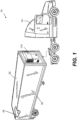
- FIG. 1 shows a vehicle 10 comprising a transport refrigeration system 20.
- the transport refrigeration system 20 forms a part of an over-the-road refrigerated semi-trailer having a structure 22 supporting (or forming) at least one climate-controlled compartment 24 which is configured to be cooled and/or heated by a TRU 110.
- the structure 22 includes a chassis.
- the structure 22 supports the TRU 110.
- the vehicle 10 further comprises a tractor unit 14 removably couplable to the trailer.
- a TRU 110 as described herein is not necessarily limited to use with an over-the-road refrigerated semi-trailer.
- the TRU could be configured for use with any other suitable type of vehicle or suitable part of a vehicle, such as a refrigerated truck, a refrigerated van, or refrigerated transport container which may be a reefer. Vapour-compression circuits as disclosed herein may also be implemented in non-TRU applications, such as HVAC(R) system.
- Figs. 2-4 schematically show a diagram of a first example refrigeration circuit 400 suitable for use with a TRU 110 (indicated schematically in the drawing) for a vehicle 10 and transport refrigeration system 20 of FIG. 1 .
- the first example vapour-compression circuit 400 is for circulating a working fluid.
- the working fluid may include, for instance, a refrigerant.
- the vapour-compression circuit 400 functions as a refrigeration circuit, as a heating circuit or as a refrigeration and heating circuit.
- the first example vapour-compression circuit 400 comprises a first compressor 402A, a second compressor 402B, a condenser 404, an expansion device 406 and an evaporator 408.
- condenser refers to respective first and second heat exchangers, with the first heat exchanger (the condenser) being configured to function as a condenser in a mode in which heat is rejected at the first heat exchanger (e.g. a cooling mode), and the second heat exchanger being configured to function as an evaporator in a mode in which heat is absorbed at the second heat exchanger (e.g. the cooling mode).
- vapour compression circuits are reversible and/or may incorporate modes for directing working fluid along different paths, and as such the condenser (first heat exchanger) and evaporator (second heat exchanger) are not required to always function as condensers and evaporators respectively.
- a discharge line 412 extends from a discharge line junction 422 (described in further detail below) to the condenser 404.
- a liquid line 414 extends from the condenser 404 to the expansion device 406, whereas a distributor line 416 extends from the expansion device 406 to the evaporator 408.
- a suction line 418 extends from the evaporator 408 to a suction line junction 428.
- Respective first and second branches 411A, 411B extend from the suction line junction 428 to the discharge line junction 422.
- the first branch 411A extends from the suction line junction 428 to the discharge line junction 422 through the first compressor 402A such that the first compressor 402A is provided on the first branch 411A.
- the second branch 411B extends from the suction line junction 428 to the discharge line junction 422 through the second compressor 402B such that the second compressor 402B is provided on the second branch 411B.
- the first example vapour-compression circuit 400 may be provided to (that is, disposed in or supported by) a vehicle 10 (see FIG. 1 ) comprising a prime mover 602A and an electric motor 602B.
- the prime mover 602A may generally be a heat engine such as an internal combustion engine (for example, a diesel-cycle internal combustion engine). If so, the first compressor 402A may be mechanically coupled to the prime mover 602A so that the first compressor 402A is configured to be driven by the prime mover 602A for the purpose of compressing working fluid in the first branch 411A.
- the second compressor 402B may be mechanically coupled to the electric motor 602B so that the second compressor 402B is configured to be driven by the electric motor 602B for the purpose of compressing working fluid in the second branch 411B.
- the prime mover 602A and the electric motor 602B are indicated in FIG. 2 in dashed lines, albeit it is to be appreciated that they may not form part of the vapour compression circuit 400 as such.
- the electric motor 602B is disposed inside a housing of the second compressor 402B. In other examples, the electric motor 602B is disposed outside a housing of the second compressor 402B.
- the prime mover 602A may generally be used to drive the first compressor 402A and thereby cause working fluid to be circulated within the vapour-compression circuit 400 when the TRU 110 is in transit (e.g., when a vehicle 10 in which the TRU 110 is incorporated is travelling on a road).
- the electric motor 602B may generally be used to drive the second compressor 402B and thereby cause working fluid to be circulated within the vapour-compression circuit 400 when the TRU 110 is not in transit (e.g., when a vehicle 10 in which the TRU 110 is incorporated is parked), when the TRU 110 is transiting a low-emissions/restricted emissions geographical area/zone, or when it is determined that there are sufficient power resources to use the electric motor 602B in place of the prime mover 602A (e.g., based on a state of charge, a planned mission/route, predicted loads and charging availability).
- the electric motor 602B may be used to drive the second compressor 402B when the TRU 110 is not in transit and an external power source is coupled to the TRU 110 for driving the second compressor 402B.
- the first compressor 402A may be referred to as a transit compressor 402A or a road compressor 402A while the second compressor 402B may be referred to as a standby compressor 402B, while acknowledging that the standby compressor 402B may still be used while in transit (e.g. as indicated above).
- Oil is used for the purpose of lubricating the first compressor 402A and/or the second compressor 402B during operation. For instance, oil may be used to lubricate moving parts of the compressor and/or provide a sealing effect. Supply of oil to the compressor(s) is of particular importance during a start-up process of the compressor(s) to avoid damage to the compressor(s).
- the first example vapour-compression circuit 400 comprises an oil separator 510 and an oil distribution network 520.
- the oil separator 510 is located along (e.g., on) the discharge line 412 between the discharge line junction 422 and the condenser 404.
- the oil separator 510 is configured to remove oil from the working fluid in the discharge line 412, with suitable oil separator designs being known to those skilled in the art.
- suitable oil separator designs being known to those skilled in the art.
- Some example oil separators operate on the principle that the oil and refrigerant have different densities, to provide gravity-based or centrifugal separation of the oil from the working fluid.
- the oil distribution network 520 is configured to re-supply oil removed from the working fluid by the oil separator 510 to a first oil supply location 522A and to a second oil supply location 522B.
- the oil distribution network 520 comprises an oil return passageway 524 which in this example bifurcates into a first oil supply passageway 524A and a second oil supply passageway 524B.
- the first oil supply passageway 524A extends from the oil return passageway 524 to the first oil supply location 522A
- the second oil supply passageway 524B extends from the oil return passageway 524 to the second oil supply location 522B.
- the oil distribution network 520 includes a valve arrangement 520 for controlling oil flow from the oil separator 510 to the first oil supply location 522A and the second oil supply location 522B.
- the valve arrangement 520 comprises a three-way valve 520 positioned where the oil return passageway 524 bifurcates into the first oil supply passageway 524A and the second oil supply passageway 524B.
- the valve arrangement 520 is configured to switch between directing oil from the oil separator 510 to (e.g. only to) the first oil supply location 522A via the first oil supply passageway 524A and to (e.g. only to) the second oil supply location 524A via the second oil supply passageway 524B.
- valve arrangement 525 comprises a three-way valve 525, this need not necessarily be the case. Additionally or alternatively, the valve arrangement 525 may comprise a plurality of valves, such as check valves, solenoid actuated valves, motor actuated valves and others to implement the same switching functionality. The plurality of valves may be arranged on the oil return passageway 524, the first oil supply passageway 524A and/or the second oil supply passageway 524B to achieve similar functionality to the three-way valve 525, as will be appreciated by those of ordinary skill in the art. Nevertheless, a three-way valve 525 may be preferred as it provides simple means for controlling oil flow within the oil distribution network 520 and may enable a control logic of the controller 490 to be relatively simple.
- the first oil supply location 522A is located at the first compressor 402A and the second oil supply location 522B is located at the second compressor 402B.
- Each of the compressors 402A, 402B comprises a respective oil sump 302A, 302B and the first oil supply location 522A is located within the oil sump 302A of the first compressor 402A whereas the second oil supply location 522B is located within the oil sump 302B of the second compressor 402B.
- each oil supply location 522A, 522B may be otherwise located within the corresponding compressor 402A, 402B.
- the first compressor 402A and the second compressor 402B are adapted to be operated by different drives (e.g., the prime mover 602A and the electric motor 602B) and under different operating conditions (e.g., when the vapour-compression circuit 400 is in transit and when the vapour-compression circuit 400 is not in transit). Therefore, the first compressor 402A and the second compressor 402B may have dissimilar features. It may be that the first compressor 402A and the second compressor 402B are different types of compressors (e.g., a reciprocating compressor, a scroll compressor, a diaphragm compressor, a centrifugal compressor and/or an axial compressor).
- a reciprocating compressor e.g., a scroll compressor, a diaphragm compressor, a centrifugal compressor and/or an axial compressor.
- the first compressor 402A may be a reciprocating compressor with swash plate(s), while the second compressor 402B may be a reciprocating compressor without swash plate(s), a rotary vane compressor, a rolling piston compressor, or a scroll compressor.
- the first compressor 402A is an open compressor
- the second compressor 402B is a hermetic or a semi-hermetic compressor.
- the first compressor 402A and the second compressor 402B may be positioned at different vertical heights within the vapour-compression circuit 400/TRU 110 to achieve space minimisation objectives.
- the compressors may have different lubrication requirements associated with their design.
- an oil capacity of the oil sump 302B of the second compressor 402B may be larger than an oil capacity of the oil sump 302A of the first compressor 402A.
- the oil capacity of the oil sump 302A of the first compressor 402A being relatively small may enable the first compressor 402 to be located in close proximity to the prime mover 602A, which is associated with a reduced overall installation size of the TRU 110 and/or greater ease of installation of the TRU 110 within a vehicle 10.
- the first compressor 402A may be located within an engine compartment in which the prime mover 602A is also located.
- the oil capacity of the oil sump 302A of the first compressor 402A being relatively small is also associated with an increased difficulty of providing sufficient oil to the first compressor 402A during use.
- the relatively large oil capacity of the second compressor 402B compared to the first compressor 402A is associated with an increased likelihood of the oil sump 302A of the first compressor 402A running dry before the start-up process is completed.
- This may also be associated with an increased likelihood of the oil sump 302B of the second compressor 402B accumulating an excessive amount of oil during operation, as described in further detail below.
- the first example vapour-compression circuit 400 also comprises a controller 490.
- the controller 490 may include a processor and/or a memory (incorporating instructions to cause the controller to operate the vapour-compression circuit as disclosed herein, upon execution by a processor), as will be appreciated by those of ordinary skill in the art.
- the controller 490 is generally configured to control each of the first compressor 402A, the second compressor 402B and the valve arrangement 525.
- the controller 490 is configured to switch between and selectively operate the first example first-vapour compression circuit 400 in a first mode, a second mode and a third mode.
- the first example vapour-compression circuit 400 is configured for operation in the first mode.
- the first example vapour-compression circuit 400 is configured for operation in the second mode.
- the first example vapour-compression circuit 400 is configured for operation in the third mode.
- the first compressor 402A compresses working fluid and the second compressor 402B is inactive (that is, does not compress working fluid, e.g., by non-rotation).
- the valve arrangement 525 is controlled by the controller 490 to direct oil from the oil separator 510 to the first oil supply location 522A.
- the controller 490 may be configured to control the valve arrangement 525 so as to preferentially direct oil to the first oil supply location 522A such that a residual and/or minor proportion of oil conveyed by the oil distribution network 520 is directed to the second oil supply location 522B when operating the vapour-compression circuit 400 in the first mode.
- controller 490 may be configured to control the valve arrangement 525 so as to only direct oil to the first oil supply location 522A such that substantially no oil conveyed by the oil distribution network 520 is directed to the second oil supply location 522B when operating the vapour-compression circuit 400 in the first mode.
- the second compressor 402B compresses working fluid and the first compressor 402A is inactive (that is, does not compress working fluid, e.g., by non-rotation).
- the valve arrangement 525 is controlled by the controller 490 to direct oil from the oil separator 510 to the second oil supply location 522B.
- the controller 490 may be configured to control the valve arrangement 525 so as to preferentially direct oil to the second oil supply location 522B such that a residual and/or minor proportion of oil conveyed by the oil distribution network 520 is directed to the first oil supply location 522A when operating the vapour-compression circuit 400 in the second mode.
- controller 490 may be configured to control the valve arrangement 525 so as to only direct oil to the second oil supply location 522B such that substantially no oil conveyed by the oil distribution network 520 is directed to the first oil supply location 522A when operating the vapour-compression circuit 400 in the second mode.
- both the first compressor 402A and the second compressor 402B are inactive (that is, do not compress working fluid).
- the valve arrangement 525 is controlled by the controller 490 to prevent oil from being supplied from the oil separator 510 to either the first oil supply location 522A or the second oil supply location 522B. Therefore, in the third mode, oil flow from the oil separator 510 to each of the first oil supply location 522A and the second oil supply location 522B is prevented.
- the third mode may be considered to correspond to an inactive or shutdown mode of the vapour-compression circuit.
- the oil separator 510 may comprise an oil reserve volume 515 configured to store oil removed from the working fluid in the discharge line 412 by the oil separator 510 for the purpose of subsequent re-supply to the first compressor 402A and/or the second compressor 402B via the oil distribution network 520.
- the oil separator 510 is unable to remove oil from working fluid in the discharge line 412.
- Preventing oil flow from the oil separator 510 to each of the first oil supply location 522A and the second oil supply location 522B when the vapour-compression circuit 400 is in the third mode ensures that oil stored in the oil reservoir 515 is retained therein rather than being supplied to, for instance, the oil sump(s) 302A, 302B of the compressor(s) 402A, 402B. As a result, a volume of oil is retained in the oil reservoir 515 of the oil separator 510 for subsequent re-supply to the first compressor 402A and/or the second compressor 402B.
- This volume of oil may be used to ensure that the or each compressor 402A, 402B is able to be supplied with a sufficient oil flow during a start-up process such that its oil sump 302A, 302B does not run dry before the start-up process is completed and a steady rate of oil flow from the oil separator 510 to the first oil supply location 522A and the second oil supply location 522B via the oil distribution network 520 is established.
- the controller 490 is configured to evaluate (e.g. determine) a running mode selection criterion.
- the running mode selection criterion is defined such that a standby outcome (e.g. output) of the criterion is indicative of the vapour-compression circuit 400 being stationary (e.g., not in transit), the vapour-compression circuit 400 being transported in a restricted-emissions geographical zone, and/or a power source (e.g., an external power source) being available for driving the second compressor 402B.
- the controller 490 may be configured to receive a signal from an external sensor and/or an external controller and to evaluate the running mode selection criterion based on the received signal.
- the controller 490 may be configured to receive a central running signal from a central controller of a vehicle 10 in which the TRU 110 is provided and/or a controller of a power source indicative of the power source being connected to the TRU 110 and available for supplying energy for driving the second compressor 402A.
- the running mode selection criterion may be defined to produce the standby outcome (e.g. output) when the central running signal has been received from the central controller or the power source.
- the controller 490 may be configured to receive a first running signal from a voltage sensor configured to monitor a voltage of an electrical bus coupled to the electric motor 602B and a second running signal from a motion sensor configured to monitor an overall acceleration or a velocity of the vapour-compression circuit 400/TRU 110.
- the running mode selection criterion may be defined to produce the standby outcome (e.g. output) based on the first running signal and the second running signal being indicative of power supply or a threshold acceleration respectively.
- the controller 490 may be configured to receive a geolocation signal from an telemetry or telecommunications device configured to monitor a geographical location of the vapour-compression circuit 400/TRU 110 and determine whether the vapour-compression circuit 400/TRU 110 is currently inside a restricted-emissions geographical zone.
- the running mode selection criterion may be defined to produce the standby outcome (e.g. output) based on the geolocation signal being indicative of the vapour-compression circuit 400/TRU 110 being currently inside a restricted-emissions geographical zone.
- the running mode selection criterion may be defined to produce the standby outcome (e.g. output) based on any appropriate received combination of the central running signal, the first running signal, the second running signal and/or the geolocation signal.
- the controller 490 is configured to select whether to operate the vapour-compression circuit 400 in the first mode or the second mode based on the outcome of the evaluation of the running mode selection criterion, and to operate the vapour-compression circuit 400 in the selected one of the first mode and the second mode accordingly. Namely, if the result of the evaluation of the running mode selection criterion is a transit outcome (e.g. output), corresponding to the vapour-compression circuit 400 being in transit and/or the power source is not available for driving the second compressor 402B, the controller 490 may select to operate the vapour-compression circuit 400 in the first mode. On the other hand, if the result of the evaluation of the running mode selection criterion is the standby outcome (e.g. output), corresponding to the vapour-compression circuit 400 not being in transit and/or the power source being available for driving the second compressor 402B, the controller 490 may select to operate the vapour-compression circuit 400 in the second mode.
- the running mode selection criterion is defined to provide an inactive outcome (e.g. output) corresponding to conditions in which compression of working fluid by the compressors 402A, 402B is not required.
- the controller 490 is configured to select to operate the vapour-compression circuit 400 in the third mode when evaluation of the running mode selection criterion results in the inactive outcome being provided.
- the controller 490 may determine that compression is not required by any suitable means, for example based on monitoring one or parameters relating to a thermal demand (e.g. a cooling or heating demand), such as a temperature of a process fluid heated or cooled by the vapour-compression circuit, and/or a temperature of the working fluid at a monitoring location in the vapour-compression circuit.
- a thermal demand e.g. a cooling or heating demand
- the running mode selection criterion may be defined to provide the inactive outcome as a function of a monitored condition (e.g. a monitored condition relating to a thermal demand as discussed above).
- the controller may be configured to receive a signal from an external sensor and/or an external controller indicating that compression is not required, and which may be used for evaluating the running mode selection criterion.
- the controller 490 may be configured to receive an inactivation signal from a central controller of a vehicle 10 in which the TRU 110 is provided and/or another controller of the TRU 110 indicative of there being no requirement to provide heating and/or cooling to a process medium (e.g., air within a climate-controlled compartment of a vehicle 10, see FIG.
- a process medium e.g., air within a climate-controlled compartment of a vehicle 10, see FIG.
- the running mode selection criterion may be defined to provide the inactive outcome upon receipt of the inactivation signal.
- the third mode may be initiated by the controller 490 to prevent the oil supply to the compressors when the controller 490 determines that the compressors 402A, 402B should be shut down.
- the controller 490 may initiate the third mode as soon as, momentarily before, or momentarily after, the compressors 402A, 402B are shut down.
- the running mode selection criterion is defined to determine whether the compressors are shut down (e.g., in an inactive state), which may result from separate control of the compressors 402A, 402B (e.g., by a separate controller).
- the third mode may be initiated by the controller 490 to prevent the oil supply to the compressors, even when the controller 490 has not directly shut down the compressors.
- the controller 490 may be configured to receive a first compressor signal from a first compressor sensor configured to monitor operation of the first compressor 402A (e.g., by monitoring an angular displacement/speed of a rotor of the first compressor 402A or a flow rate of working fluid in to or out of the first compressor 402A) and a second compressor signal from a second compressor sensor configured to monitor operation of the second compressor 402B (e.g., by monitoring a displacement of a rotor of the second compressor 402B or a flow rate of working fluid in to or out of the second compressor 402B).
- the running mode selection criterion may be defined to determine the inactive outcome based on the first compressor signal and the second compressor signal being indicative of both compressors being shut down.
- the controller 490 is configured to select whether to operate the vapour-compression circuit 400 in the third mode based on the outcome of the evaluation of the running mode selection criterion, and to operate the vapour-compression circuit 400 in the third mode when the inactive outcome is determined.
- the arrangements of the vapour-compression circuit 400 ensure that either or both of the compressor(s) are able to effectively operate to compress working fluid while being supplied with sufficient oil for this purpose, especially while performing a start-up process. This is associated with improved performance of the vapour-compression circuit 400 and reduced wear levels on critical components (e.g. in the compressors(s) 402A, 402B) thereby minimising a probability of failure during use. Further, the arrangements of the example vapour-compression circuits 400, 400' described herein provide relatively simple means for supplying oil to a pair of compressors 402A, 402B provided in parallel branches between a suction line 418 and a discharge line 412.
- a previously-considered system design featured an in-line oil reservoir located along a suction line between an evaporator and a suction line junction similar to that described herein.
- such an in-line oil reservoir would store oil received from an oil separator for injection into the working fluid within the suction line.
- a size and/or a location of the in-line oil reservoir may be selected so that sufficient oil flow may be provided to a first compressor and/or a second compressor in a similar parallel branch arrangement to that described herein, during a start-up process of either compressor.
- the size of the in-line oil reservoir may be selected so that the first compressor receives enough oil during a start-up process considering a size of its oil sump.
- the oil capacity of the oil sump of the first compressor is relatively small (that is, is smaller than the oil capacity of the oil sump of the second compressor), as may be the case in the context of a vapour-compression circuit adapted for use in transport contexts (e.g., forming part of a TRU), this consideration may favour the selection of a relatively large size of the in-line oil reservoir.
- sizing of the in-line oil reservoir in this way may lead to excess oil being cyclically injected into the suction line and removed from the discharge line when only one of the compressors is running at steady state. Excess oil in the working fluid is associated with a capacity reduction of a vapour-compression circuit.
- the inventors found that the inclusion of the in-line oil reservoir along the suction line 418 introduced a significant pressure drop in working fluid circulated around the vapour-compression circuit in use. In turn, this resulted in a relatively decreased energy efficiency of the vapour-compression circuit. Further, in the previously-considered system, the inventors found that pre-installation modifications to the oil sump 302B of the second compressor 402B may be required to prevent the oil sump 302B of the second compressor 402B from accumulating an excessive amount of oil in use. Such pre-installation modifications included adding an oil drain connection in the oil sump 302B of the second compressor 402B.
- the arrangements of the example vapour-compression circuits 400, 400' described herein dispense with any need to include such an in-line oil reservoir, and thereby facilitate improved capacity and/or energy efficiency of the vapour-compression circuits 400, 400'. Additionally, the arrangements of the example vapour-compression circuits 400, 400' described herein may dispense with any need to make pre-installation modifications to the oil sump 302B of the second compressor 402B to prevent the oil sump 302B of the second compressor 402B from accumulating an excessive amount of oil in use.
- vapour-compression circuit 400 oil may be provided directly at the first compressor 402A and the second compressor 402B by the oil distribution network 520. Accordingly, oil need not be injected into working fluid within the suction line 418 and/or the branches 411A, 411B.
- oil supplied by the oil distribution network 520 to either the first oil supply location 522A or the second oil supply location 522B does not mix with, and so does not directly heat, working fluid before it is supplied to the respective compressor 402A, 402B. It follows that working fluid in the suction line 418 and/or the branches 411A, 411B is not subject to excessive heating as a result of re-supply of oil to the compressor(s) by the oil distribution network 520. This leads to a relatively reduced temperature of working fluid in the discharge line 412.
- oil may be cooled (e.g., passively cooled) within the oil distribution network 520.
- oil may be subject to significant passive cooling within the first oil supply passageway 524A due to a relatively large distance between the first oil supply location 522A (especially if the first oil supply location 522A is within the oil sump 302A of the first compressor 402A) and the valve arrangement 525 and/or the oil separator 510. This may lead to further relatively reduced temperature of working fluid in the discharge line 412.
- a reduced working fluid temperature in the discharge line 412 enables a greater variety of architectures to be used for the other components of the vapour-compression circuit 400 (e.g., the condenser 404) and also enables a wider range of refrigerants to be used as part of the working fluid.
- GWP global warming potential
- reducing the working fluid temperature in the discharge line 412 may enable a working fluid comprising a refrigerant with a lower GWP to be used, thereby permitting a reduced environmental impact of operation of the vapour-compression circuit.
- An exemplary low GWP refrigerant which tends to exhibit such higher temperatures in the discharge line is R454A.
- Figs. 5-7 schematically show a diagram of a second example refrigeration circuit 400' suitable for use with a TRU 110' (indicated schematically in the drawing) for a vehicle 10 and the transport refrigeration system 20 of FIG. 1 .
- the second vapour-compression circuit 400' is generally similar to the first example vapour-compression circuit 400 described above with respect to Figs. 2-4 , with like reference numerals denoting common or similar features.
- the controller 490 of the second example vapour-compression circuit 400' is configured to selectively operate the second example first-vapour compression circuit 400' in the first mode, the second mode and the third mode.
- the second example vapour-compression circuit 400' is configured for operation in the first mode.
- the second example vapour-compression circuit 400' is configured for operation in the second mode.
- the second example vapour-compression circuit 400' is configured for operation in the third mode.
- the first oil supply location 522A' is located upstream of the first compressor 402A along the first branch 411A and the second oil supply location 522B' is located upstream of the second compressor 402B along the second branch 411B.
- the first oil supply location 522A' is located between the suction line junction 428 and the first compressor 402A along the first branch 411A
- the second oil supply location 522B' is located between the suction line junction 428 and the second compressor 402B along the second branch 411B.
- the controller(s) described herein may comprise a processor.
- the controller and/or the processor may comprise any suitable circuity to cause performance of the methods described herein and as illustrated in the drawings.
- the controller or processor may comprise: at least one application specific integrated circuit (ASIC); and/or at least one field programmable gate array (FPGA); and/or single or multi-processor architectures; and/or sequential (Von Neumann)/parallel architectures; and/or at least one programmable logic controllers (PLCs); and/or at least one microprocessor; and/or at least one microcontroller; and/or a central processing unit (CPU), to perform the methods and or stated functions for which the controller or processor is configured.
- ASIC application specific integrated circuit
- FPGA field programmable gate array
- PLCs programmable logic controllers
- microprocessor and/or at least one microcontroller
- CPU central processing unit
- the controller or the processor may comprise or be in communication with one or more memories that store that data described herein, and/or that store machine readable instructions (e.g., software) for performing the processes and functions described herein (e.g., determinations of parameters and execution of control routines).
- the memory may be any suitable non-transitory computer readable storage medium, data storage device or devices, and may comprise a hard disk and/or solid state memory (such as flash memory).
- the computer readable instructions may be transferred to the memory via a wireless signal or via a wired signal.
- the memory may be permanent non-removable memory or may be removable memory (such as a universal serial bus (USB) flash drive).
- the memory may store a computer program comprising computer readable instructions that, when read by a processor or controller, causes performance of the methods described herein, and/or as illustrated in the Figures.
- the computer program may be software or firmware or be a combination of software and firmware.
Landscapes
- Engineering & Computer Science (AREA)
- Physics & Mathematics (AREA)
- Mechanical Engineering (AREA)
- Thermal Sciences (AREA)
- General Engineering & Computer Science (AREA)
- Chemical & Material Sciences (AREA)
- Analytical Chemistry (AREA)
- Power Engineering (AREA)
- Control Of Positive-Displacement Pumps (AREA)
Abstract
The present disclosure relates to a vapour-compression circuit 400, 400' for circulating a working fluid. The vapour-compression circuit 400, 400' comprises: a first compressor 402A, a second compressor 402B, a suction line 418, a discharge line 412, an oil separator 510 and an oil distribution network 520. The first compressor 402A and the second compressor 402B are provided in respective first 411A and second 411B parallel branches between the suction line 418 and the discharge line 412. The oil separator 510 is located along the discharge line 412 and is configured to remove oil from working fluid in the discharge line 418. The oil distribution network 520 is configured to re-supply oil removed from the working fluid by the oil separator 510 to a first oil supply location 522A, 522A' at or upstream of the first compressor 402A along the first branch 411A, and also to a second oil supply location 522B, 522B' at or upstream of the second compressor 402B along the second branch 411B.
Description
- The present disclosure relates to a vapour-compression circuit comprising a pair of compressors provided in parallel branches between a suction line and a discharge line of the vapour-compression circuit. The present disclosure also relates to a transport refrigeration unit (TRU) and a vehicle comprising such a vapour-compression circuit.
- It is known to provide a vapour-compression circuit comprising a pair of compressors, with each compressor being provided on a respective parallel branch. If a vapour-compression circuit is incorporated within a TRU, each compressor may be mechanically coupled to alternative driving means, such as a prime mover and an electric motor, respectively. The alternative driving means may be used to drive the corresponding compressor under different operational conditions as may be deemed necessary or advantageous.
- It is desirable to provide an improved vapour-compression circuit for use as part of a TRU and/or a vehicle, the vapour-compression circuit comprising a plurality of compressors which are operable under different operational conditions of the TRU and/or the vehicle. In particular, it is desirable to provide such a vapour-compression circuit with improved means for ensuring adequate lubrication of each of the compressors during use.
-
JP5001730B2 JP5554039B2 - According to a first aspect there is provided a vapour-compression circuit for circulating a working fluid, the vapour-compression circuit comprising: a first compressor, a second compressor provided in respective first and second parallel branches between a suction line and a discharge line of the vapour-compression circuit, an oil separator and an oil distribution network, wherein the oil separator is located along the discharge line and is configured to remove oil from working fluid in the discharge line; and the oil distribution network is configured to re-supply oil removed from the working fluid by the oil separator to a first oil supply location at or upstream of the first compressor along the first branch, and to a second oil supply location at or upstream of the second compressor along the second branch.
- It may be that the first oil supply location is at the first compressor and/or the second oil supply location is at the second compressor. The first compressor may include an oil sump, and the first oil supply location may be within the oil sump of the first compressor. The second compressor may include an oil sump, and the second oil supply location may be within the oil sump of the second compressor.
- It may be that the first compressor includes an oil sump, the second compressor includes an oil sump, and an oil capacity of the oil sump of the second compressor is larger than an oil capacity of the oil sump of the first compressor.
- The oil distribution network may comprise a valve arrangement configured to switch between directing oil to the first oil supply location and to the second oil supply location. The valve arrangement may be configured to switch between directing oil to the first oil supply location in a first mode of vapour-compression circuit and to the second oil supply location in a second mode of the vapour-compression circuit. It may be that, in the first mode, the valve arrangement directs oil only to the first oil supply location. It may be that, in the second mode, the valve arrangement directs oil only to the second oil supply location. The valve arrangement may comprise a three-way valve.
- It may be that the vapour-compression circuit comprises a controller configured to:
- control the first and second compressors; and switch between a first mode in which the first compressor compresses the working fluid and the second compressor is inactive, and
- a second mode in which the second compressor compresses the working fluid and the first compressor is inactive.
- It may be that the controller is configured to: in the first mode, control the valve arrangement to direct oil to the first oil supply location; and in the second mode, control the valve arrangement to direct oil to the second oil supply location.
- It may be that in the first mode, the valve arrangement is controlled to preferentially direct oil to the first oil supply location such that a residual and/or minor proportion of oil conveyed by the oil distribution network is directed to the second oil supply location. It may be that in the second mode, the valve arrangement is controlled to preferentially direct oil to the second oil supply location such that a residual and/or minor proportion of oil conveyed by the oil distribution network is directed to the first oil supply location.
- It may be that controller is configured to: in the first mode, control the valve arrangement to only direct oil to the first oil supply location; and in the second mode, control the valve arrangement to only direct oil to the second oil supply location.
- The controller may be configured to: determine whether to operate the vapour-compression circuit in the first mode or the second mode by determining a mode selection criterion having respective outcomes, wherein a first outcome is indicative of: the vapour-compression circuit being stationary, the vapour-compression circuit being transported in a restricted-emissions geographical zone, and/or a power source being available to drive the second compressor; and operate the vapour-compression circuit in a selected one of the first mode and the second mode based on the determination. It may be that the controller is configured to determine the mode selection criterion based on a signal received from an external sensor or from an external controller.
- It may be that the controller is configured to selectively control the first compressor and the second compressor to be inactive; and the vapour-compression circuit is configured so that oil flow from the oil separator to each of the first oil supply location and the second oil supply location is prevented when the first compressor and the second compressor are inactive.
- The controller may be configured to control the valve arrangement to prevent oil being directed via the distribution network to any of the first oil supply location and the second oil supply location. The oil separator may comprise an oil reserve volume configured to store oil removed from the working fluid in the discharge line for subsequent re-supply to the first compressor and/or the second compressor via the oil distribution network.
- According to a second aspect there is provided a transport refrigeration unit (TRU) comprising a vapour-compression circuit in accordance with the first aspect.
- According to a third aspect there is provided a vehicle comprising a vapour-compression circuit in accordance with the first aspect and/or a TRU in accordance with the second aspect. It may be that the vehicle comprises a prime mover and an electric motor. The first compressor may be mechanically coupled to the prime mover and/or the second compressor may be mechanically coupled to the electric motor. The prime mover may be a heat engine such as an internal combustion engine.
-
-
FIG. 1 shows a vehicle comprising a transport refrigeration system; -
FIG. 2 is a diagram which schematically shows a transport refrigeration unit suitable for use with the transport refrigeration system ofFIG. 1 , the transport refrigeration unit comprising a first example vapour-compression circuit being configured for operation in a first mode; -
FIG. 3 is a diagram of the transport refrigeration unit ofFIG. 2 configured for operation in a second mode; -
FIG. 4 is a diagram of the transport refrigeration unit ofFigs. 2 and3 configured for operation in a third mode; -
FIG. 5 is a diagram which schematically shows a transport refrigeration unit suitable for use with the transport refrigeration system ofFIG. 1 , the transport refrigeration unit comprising a second example vapour-compression circuit being configured for operation in a first mode; -
FIG. 6 is a diagram of the transport refrigeration unit ofFIG. 5 configured for operation in a second mode; and -
FIG. 7 is a diagram of the transport refrigeration unit ofFigs. 5 and6 configured for operation in a third mode. -
FIG. 1 shows avehicle 10 comprising atransport refrigeration system 20. In the example ofFIG. 1 , thetransport refrigeration system 20 forms a part of an over-the-road refrigerated semi-trailer having astructure 22 supporting (or forming) at least one climate-controlledcompartment 24 which is configured to be cooled and/or heated by a TRU 110. Thestructure 22 includes a chassis. Thestructure 22 supports the TRU 110. Thevehicle 10 further comprises atractor unit 14 removably couplable to the trailer. However, it should be noted that a TRU 110 as described herein is not necessarily limited to use with an over-the-road refrigerated semi-trailer. The TRU could be configured for use with any other suitable type of vehicle or suitable part of a vehicle, such as a refrigerated truck, a refrigerated van, or refrigerated transport container which may be a reefer. Vapour-compression circuits as disclosed herein may also be implemented in non-TRU applications, such as HVAC(R) system. -
Figs. 2-4 schematically show a diagram of a firstexample refrigeration circuit 400 suitable for use with a TRU 110 (indicated schematically in the drawing) for avehicle 10 andtransport refrigeration system 20 ofFIG. 1 . The first example vapour-compression circuit 400 is for circulating a working fluid. The working fluid may include, for instance, a refrigerant. In use, the vapour-compression circuit 400 functions as a refrigeration circuit, as a heating circuit or as a refrigeration and heating circuit. The first example vapour-compression circuit 400 comprises afirst compressor 402A, asecond compressor 402B, acondenser 404, anexpansion device 406 and anevaporator 408. The expressions "condenser", "evaporator" refer to respective first and second heat exchangers, with the first heat exchanger (the condenser) being configured to function as a condenser in a mode in which heat is rejected at the first heat exchanger (e.g. a cooling mode), and the second heat exchanger being configured to function as an evaporator in a mode in which heat is absorbed at the second heat exchanger (e.g. the cooling mode). Such a mode is described below, although it is to be appreciated that various vapour compression circuits are reversible and/or may incorporate modes for directing working fluid along different paths, and as such the condenser (first heat exchanger) and evaporator (second heat exchanger) are not required to always function as condensers and evaporators respectively. - A
discharge line 412 extends from a discharge line junction 422 (described in further detail below) to thecondenser 404. Aliquid line 414 extends from thecondenser 404 to theexpansion device 406, whereas adistributor line 416 extends from theexpansion device 406 to theevaporator 408. Asuction line 418 extends from theevaporator 408 to asuction line junction 428. - Respective first and
second branches suction line junction 428 to thedischarge line junction 422. Thefirst branch 411A extends from thesuction line junction 428 to thedischarge line junction 422 through thefirst compressor 402A such that thefirst compressor 402A is provided on thefirst branch 411A. Correspondingly, thesecond branch 411B extends from thesuction line junction 428 to thedischarge line junction 422 through thesecond compressor 402B such that thesecond compressor 402B is provided on thesecond branch 411B. - The first example vapour-
compression circuit 400 may be provided to (that is, disposed in or supported by) a vehicle 10 (seeFIG. 1 ) comprising aprime mover 602A and anelectric motor 602B. Theprime mover 602A may generally be a heat engine such as an internal combustion engine (for example, a diesel-cycle internal combustion engine). If so, thefirst compressor 402A may be mechanically coupled to theprime mover 602A so that thefirst compressor 402A is configured to be driven by theprime mover 602A for the purpose of compressing working fluid in thefirst branch 411A. In a similar way, thesecond compressor 402B may be mechanically coupled to theelectric motor 602B so that thesecond compressor 402B is configured to be driven by theelectric motor 602B for the purpose of compressing working fluid in thesecond branch 411B. Theprime mover 602A and theelectric motor 602B are indicated inFIG. 2 in dashed lines, albeit it is to be appreciated that they may not form part of thevapour compression circuit 400 as such. In some examples, theelectric motor 602B is disposed inside a housing of thesecond compressor 402B. In other examples, theelectric motor 602B is disposed outside a housing of thesecond compressor 402B. - The
prime mover 602A may generally be used to drive thefirst compressor 402A and thereby cause working fluid to be circulated within the vapour-compression circuit 400 when theTRU 110 is in transit (e.g., when avehicle 10 in which theTRU 110 is incorporated is travelling on a road). On the other hand, theelectric motor 602B may generally be used to drive thesecond compressor 402B and thereby cause working fluid to be circulated within the vapour-compression circuit 400 when theTRU 110 is not in transit (e.g., when avehicle 10 in which theTRU 110 is incorporated is parked), when theTRU 110 is transiting a low-emissions/restricted emissions geographical area/zone, or when it is determined that there are sufficient power resources to use theelectric motor 602B in place of theprime mover 602A (e.g., based on a state of charge, a planned mission/route, predicted loads and charging availability). In particular, theelectric motor 602B may be used to drive thesecond compressor 402B when theTRU 110 is not in transit and an external power source is coupled to theTRU 110 for driving thesecond compressor 402B. Consequently, thefirst compressor 402A may be referred to as atransit compressor 402A or aroad compressor 402A while thesecond compressor 402B may be referred to as astandby compressor 402B, while acknowledging that thestandby compressor 402B may still be used while in transit (e.g. as indicated above). - Oil is used for the purpose of lubricating the
first compressor 402A and/or thesecond compressor 402B during operation. For instance, oil may be used to lubricate moving parts of the compressor and/or provide a sealing effect. Supply of oil to the compressor(s) is of particular importance during a start-up process of the compressor(s) to avoid damage to the compressor(s). - In use, oil which is used for the purpose of lubricating the
first compressor 402A and/or thesecond compressor 402B is mixed within the working fluid is discharged from the compressor(s) 402A, 402B. The first example vapour-compression circuit 400 comprises anoil separator 510 and anoil distribution network 520. - The
oil separator 510 is located along (e.g., on) thedischarge line 412 between thedischarge line junction 422 and thecondenser 404. Theoil separator 510 is configured to remove oil from the working fluid in thedischarge line 412, with suitable oil separator designs being known to those skilled in the art. Some example oil separators operate on the principle that the oil and refrigerant have different densities, to provide gravity-based or centrifugal separation of the oil from the working fluid. - The
oil distribution network 520 is configured to re-supply oil removed from the working fluid by theoil separator 510 to a firstoil supply location 522A and to a secondoil supply location 522B. To this end, theoil distribution network 520 comprises anoil return passageway 524 which in this example bifurcates into a firstoil supply passageway 524A and a secondoil supply passageway 524B. The firstoil supply passageway 524A extends from theoil return passageway 524 to the firstoil supply location 522A, whereas the secondoil supply passageway 524B extends from theoil return passageway 524 to the secondoil supply location 522B. - The
oil distribution network 520 includes avalve arrangement 520 for controlling oil flow from theoil separator 510 to the firstoil supply location 522A and the secondoil supply location 522B. In the example ofFigs. 2-4 , thevalve arrangement 520 comprises a three-way valve 520 positioned where theoil return passageway 524 bifurcates into the firstoil supply passageway 524A and the secondoil supply passageway 524B. Thevalve arrangement 520 is configured to switch between directing oil from theoil separator 510 to (e.g. only to) the firstoil supply location 522A via the firstoil supply passageway 524A and to (e.g. only to) the secondoil supply location 524A via the secondoil supply passageway 524B. - Although it has been described that the
valve arrangement 525 comprises a three-way valve 525, this need not necessarily be the case. Additionally or alternatively, thevalve arrangement 525 may comprise a plurality of valves, such as check valves, solenoid actuated valves, motor actuated valves and others to implement the same switching functionality. The plurality of valves may be arranged on theoil return passageway 524, the firstoil supply passageway 524A and/or the secondoil supply passageway 524B to achieve similar functionality to the three-way valve 525, as will be appreciated by those of ordinary skill in the art. Nevertheless, a three-way valve 525 may be preferred as it provides simple means for controlling oil flow within theoil distribution network 520 and may enable a control logic of thecontroller 490 to be relatively simple. - In the first example
vapour compression circuit 400, the firstoil supply location 522A is located at thefirst compressor 402A and the secondoil supply location 522B is located at thesecond compressor 402B. Each of thecompressors respective oil sump oil supply location 522A is located within theoil sump 302A of thefirst compressor 402A whereas the secondoil supply location 522B is located within theoil sump 302B of thesecond compressor 402B. However, it is envisaged that eachoil supply location corresponding compressor - As discussed above, the
first compressor 402A and thesecond compressor 402B are adapted to be operated by different drives (e.g., theprime mover 602A and theelectric motor 602B) and under different operating conditions (e.g., when the vapour-compression circuit 400 is in transit and when the vapour-compression circuit 400 is not in transit). Therefore, thefirst compressor 402A and thesecond compressor 402B may have dissimilar features. It may be that thefirst compressor 402A and thesecond compressor 402B are different types of compressors (e.g., a reciprocating compressor, a scroll compressor, a diaphragm compressor, a centrifugal compressor and/or an axial compressor). Specifically, thefirst compressor 402A may be a reciprocating compressor with swash plate(s), while thesecond compressor 402B may be a reciprocating compressor without swash plate(s), a rotary vane compressor, a rolling piston compressor, or a scroll compressor. In addition, it may be that thefirst compressor 402A is an open compressor, whereas thesecond compressor 402B is a hermetic or a semi-hermetic compressor. Further, thefirst compressor 402A and thesecond compressor 402B may be positioned at different vertical heights within the vapour-compression circuit 400/TRU 110 to achieve space minimisation objectives. Further, the compressors may have different lubrication requirements associated with their design. In particular, an oil capacity of theoil sump 302B of thesecond compressor 402B may be larger than an oil capacity of theoil sump 302A of thefirst compressor 402A. - The oil capacity of the
oil sump 302A of thefirst compressor 402A being relatively small may enable the first compressor 402 to be located in close proximity to theprime mover 602A, which is associated with a reduced overall installation size of theTRU 110 and/or greater ease of installation of theTRU 110 within avehicle 10. For instance, thefirst compressor 402A may be located within an engine compartment in which theprime mover 602A is also located. However, the oil capacity of theoil sump 302A of thefirst compressor 402A being relatively small is also associated with an increased difficulty of providing sufficient oil to thefirst compressor 402A during use. In other words, the relatively large oil capacity of thesecond compressor 402B compared to thefirst compressor 402A is associated with an increased likelihood of theoil sump 302A of thefirst compressor 402A running dry before the start-up process is completed. This may also be associated with an increased likelihood of theoil sump 302B of thesecond compressor 402B accumulating an excessive amount of oil during operation, as described in further detail below. - The first example vapour-
compression circuit 400 also comprises acontroller 490. Thecontroller 490 may include a processor and/or a memory (incorporating instructions to cause the controller to operate the vapour-compression circuit as disclosed herein, upon execution by a processor), as will be appreciated by those of ordinary skill in the art. - The
controller 490 is generally configured to control each of thefirst compressor 402A, thesecond compressor 402B and thevalve arrangement 525. Thecontroller 490 is configured to switch between and selectively operate the first example first-vapour compression circuit 400 in a first mode, a second mode and a third mode. InFIG. 2 , the first example vapour-compression circuit 400 is configured for operation in the first mode. InFIG. 3 , the first example vapour-compression circuit 400 is configured for operation in the second mode. InFIG. 4 , the first example vapour-compression circuit 400 is configured for operation in the third mode. - When the vapour-
compression circuit 400 is operated in the first mode (seeFIG. 2 ) by thecontroller 490, thefirst compressor 402A compresses working fluid and thesecond compressor 402B is inactive (that is, does not compress working fluid, e.g., by non-rotation). Further, in the first mode, thevalve arrangement 525 is controlled by thecontroller 490 to direct oil from theoil separator 510 to the firstoil supply location 522A. Thecontroller 490 may be configured to control thevalve arrangement 525 so as to preferentially direct oil to the firstoil supply location 522A such that a residual and/or minor proportion of oil conveyed by theoil distribution network 520 is directed to the secondoil supply location 522B when operating the vapour-compression circuit 400 in the first mode. Alternatively, thecontroller 490 may be configured to control thevalve arrangement 525 so as to only direct oil to the firstoil supply location 522A such that substantially no oil conveyed by theoil distribution network 520 is directed to the secondoil supply location 522B when operating the vapour-compression circuit 400 in the first mode. - When the vapour-
compression circuit 400 is operated in the second mode (seeFIG. 3 ) by thecontroller 490, thesecond compressor 402B compresses working fluid and thefirst compressor 402A is inactive (that is, does not compress working fluid, e.g., by non-rotation). Also, in the second mode, thevalve arrangement 525 is controlled by thecontroller 490 to direct oil from theoil separator 510 to the secondoil supply location 522B. Thecontroller 490 may be configured to control thevalve arrangement 525 so as to preferentially direct oil to the secondoil supply location 522B such that a residual and/or minor proportion of oil conveyed by theoil distribution network 520 is directed to the firstoil supply location 522A when operating the vapour-compression circuit 400 in the second mode. Alternatively, thecontroller 490 may be configured to control thevalve arrangement 525 so as to only direct oil to the secondoil supply location 522B such that substantially no oil conveyed by theoil distribution network 520 is directed to the firstoil supply location 522A when operating the vapour-compression circuit 400 in the second mode. - When the vapour-
compression circuit 400 is operated in the third mode (seeFIG. 4 ) by thecontroller 490, both thefirst compressor 402A and thesecond compressor 402B are inactive (that is, do not compress working fluid). Also, in the third mode, thevalve arrangement 525 is controlled by thecontroller 490 to prevent oil from being supplied from theoil separator 510 to either the firstoil supply location 522A or the secondoil supply location 522B. Therefore, in the third mode, oil flow from theoil separator 510 to each of the firstoil supply location 522A and the secondoil supply location 522B is prevented. The third mode may be considered to correspond to an inactive or shutdown mode of the vapour-compression circuit. - The
oil separator 510 may comprise anoil reserve volume 515 configured to store oil removed from the working fluid in thedischarge line 412 by theoil separator 510 for the purpose of subsequent re-supply to thefirst compressor 402A and/or thesecond compressor 402B via theoil distribution network 520. Generally, when neither thefirst compressor 402A nor thesecond compressor 402B is running (i.e., compressing working fluid), theoil separator 510 is unable to remove oil from working fluid in thedischarge line 412. Preventing oil flow from theoil separator 510 to each of the firstoil supply location 522A and the secondoil supply location 522B when the vapour-compression circuit 400 is in the third mode ensures that oil stored in theoil reservoir 515 is retained therein rather than being supplied to, for instance, the oil sump(s) 302A, 302B of the compressor(s) 402A, 402B. As a result, a volume of oil is retained in theoil reservoir 515 of theoil separator 510 for subsequent re-supply to thefirst compressor 402A and/or thesecond compressor 402B. This volume of oil may be used to ensure that the or eachcompressor oil sump oil separator 510 to the firstoil supply location 522A and the secondoil supply location 522B via theoil distribution network 520 is established. - The
controller 490 is configured to evaluate (e.g. determine) a running mode selection criterion. The running mode selection criterion is defined such that a standby outcome (e.g. output) of the criterion is indicative of the vapour-compression circuit 400 being stationary (e.g., not in transit), the vapour-compression circuit 400 being transported in a restricted-emissions geographical zone, and/or a power source (e.g., an external power source) being available for driving thesecond compressor 402B. Thecontroller 490 may be configured to receive a signal from an external sensor and/or an external controller and to evaluate the running mode selection criterion based on the received signal. By way of example, thecontroller 490 may be configured to receive a central running signal from a central controller of avehicle 10 in which theTRU 110 is provided and/or a controller of a power source indicative of the power source being connected to theTRU 110 and available for supplying energy for driving thesecond compressor 402A. The running mode selection criterion may be defined to produce the standby outcome (e.g. output) when the central running signal has been received from the central controller or the power source. By way of further example, thecontroller 490 may be configured to receive a first running signal from a voltage sensor configured to monitor a voltage of an electrical bus coupled to theelectric motor 602B and a second running signal from a motion sensor configured to monitor an overall acceleration or a velocity of the vapour-compression circuit 400/TRU 110. The running mode selection criterion may be defined to produce the standby outcome (e.g. output) based on the first running signal and the second running signal being indicative of power supply or a threshold acceleration respectively. By way of yet further example, thecontroller 490 may be configured to receive a geolocation signal from an telemetry or telecommunications device configured to monitor a geographical location of the vapour-compression circuit 400/TRU 110 and determine whether the vapour-compression circuit 400/TRU 110 is currently inside a restricted-emissions geographical zone. The running mode selection criterion may be defined to produce the standby outcome (e.g. output) based on the geolocation signal being indicative of the vapour-compression circuit 400/TRU 110 being currently inside a restricted-emissions geographical zone. The running mode selection criterion may be defined to produce the standby outcome (e.g. output) based on any appropriate received combination of the central running signal, the first running signal, the second running signal and/or the geolocation signal. - The
controller 490 is configured to select whether to operate the vapour-compression circuit 400 in the first mode or the second mode based on the outcome of the evaluation of the running mode selection criterion, and to operate the vapour-compression circuit 400 in the selected one of the first mode and the second mode accordingly. Namely, if the result of the evaluation of the running mode selection criterion is a transit outcome (e.g. output), corresponding to the vapour-compression circuit 400 being in transit and/or the power source is not available for driving thesecond compressor 402B, thecontroller 490 may select to operate the vapour-compression circuit 400 in the first mode. On the other hand, if the result of the evaluation of the running mode selection criterion is the standby outcome (e.g. output), corresponding to the vapour-compression circuit 400 not being in transit and/or the power source being available for driving thesecond compressor 402B, thecontroller 490 may select to operate the vapour-compression circuit 400 in the second mode. - In this example, the running mode selection criterion is defined to provide an inactive outcome (e.g. output) corresponding to conditions in which compression of working fluid by the
compressors controller 490 is configured to select to operate the vapour-compression circuit 400 in the third mode when evaluation of the running mode selection criterion results in the inactive outcome being provided. Thecontroller 490 may determine that compression is not required by any suitable means, for example based on monitoring one or parameters relating to a thermal demand (e.g. a cooling or heating demand), such as a temperature of a process fluid heated or cooled by the vapour-compression circuit, and/or a temperature of the working fluid at a monitoring location in the vapour-compression circuit. The running mode selection criterion may be defined to provide the inactive outcome as a function of a monitored condition (e.g. a monitored condition relating to a thermal demand as discussed above). The controller may be configured to receive a signal from an external sensor and/or an external controller indicating that compression is not required, and which may be used for evaluating the running mode selection criterion. As an example, thecontroller 490 may be configured to receive an inactivation signal from a central controller of avehicle 10 in which theTRU 110 is provided and/or another controller of theTRU 110 indicative of there being no requirement to provide heating and/or cooling to a process medium (e.g., air within a climate-controlled compartment of avehicle 10, seeFIG. 1 ) and/or a demand to terminate operation of the vapour-compression circuit 400. The running mode selection criterion may be defined to provide the inactive outcome upon receipt of the inactivation signal. In this way, the third mode may be initiated by thecontroller 490 to prevent the oil supply to the compressors when thecontroller 490 determines that thecompressors controller 490 may initiate the third mode as soon as, momentarily before, or momentarily after, thecompressors - As another example, it may be that the running mode selection criterion is defined to determine whether the compressors are shut down (e.g., in an inactive state), which may result from separate control of the
compressors controller 490 to prevent the oil supply to the compressors, even when thecontroller 490 has not directly shut down the compressors. For example, thecontroller 490 may be configured to receive a first compressor signal from a first compressor sensor configured to monitor operation of thefirst compressor 402A (e.g., by monitoring an angular displacement/speed of a rotor of thefirst compressor 402A or a flow rate of working fluid in to or out of thefirst compressor 402A) and a second compressor signal from a second compressor sensor configured to monitor operation of thesecond compressor 402B (e.g., by monitoring a displacement of a rotor of thesecond compressor 402B or a flow rate of working fluid in to or out of thesecond compressor 402B). The running mode selection criterion may be defined to determine the inactive outcome based on the first compressor signal and the second compressor signal being indicative of both compressors being shut down. - The
controller 490 is configured to select whether to operate the vapour-compression circuit 400 in the third mode based on the outcome of the evaluation of the running mode selection criterion, and to operate the vapour-compression circuit 400 in the third mode when the inactive outcome is determined. - The arrangements of the vapour-
compression circuit 400 ensure that either or both of the compressor(s) are able to effectively operate to compress working fluid while being supplied with sufficient oil for this purpose, especially while performing a start-up process. This is associated with improved performance of the vapour-compression circuit 400 and reduced wear levels on critical components (e.g. in the compressors(s) 402A, 402B) thereby minimising a probability of failure during use. Further, the arrangements of the example vapour-compression circuits 400, 400' described herein provide relatively simple means for supplying oil to a pair ofcompressors suction line 418 and adischarge line 412. - A previously-considered system design featured an in-line oil reservoir located along a suction line between an evaporator and a suction line junction similar to that described herein. In use, such an in-line oil reservoir would store oil received from an oil separator for injection into the working fluid within the suction line. A size and/or a location of the in-line oil reservoir may be selected so that sufficient oil flow may be provided to a first compressor and/or a second compressor in a similar parallel branch arrangement to that described herein, during a start-up process of either compressor. In particular, the size of the in-line oil reservoir may be selected so that the first compressor receives enough oil during a start-up process considering a size of its oil sump. If the oil capacity of the oil sump of the first compressor is relatively small (that is, is smaller than the oil capacity of the oil sump of the second compressor), as may be the case in the context of a vapour-compression circuit adapted for use in transport contexts (e.g., forming part of a TRU), this consideration may favour the selection of a relatively large size of the in-line oil reservoir. However, sizing of the in-line oil reservoir in this way may lead to excess oil being cyclically injected into the suction line and removed from the discharge line when only one of the compressors is running at steady state. Excess oil in the working fluid is associated with a capacity reduction of a vapour-compression circuit. In addition, the inventors found that the inclusion of the in-line oil reservoir along the
suction line 418 introduced a significant pressure drop in working fluid circulated around the vapour-compression circuit in use. In turn, this resulted in a relatively decreased energy efficiency of the vapour-compression circuit. Further, in the previously-considered system, the inventors found that pre-installation modifications to theoil sump 302B of thesecond compressor 402B may be required to prevent theoil sump 302B of thesecond compressor 402B from accumulating an excessive amount of oil in use. Such pre-installation modifications included adding an oil drain connection in theoil sump 302B of thesecond compressor 402B. - The arrangements of the example vapour-
compression circuits 400, 400' described herein dispense with any need to include such an in-line oil reservoir, and thereby facilitate improved capacity and/or energy efficiency of the vapour-compression circuits 400, 400'. Additionally, the arrangements of the example vapour-compression circuits 400, 400' described herein may dispense with any need to make pre-installation modifications to theoil sump 302B of thesecond compressor 402B to prevent theoil sump 302B of thesecond compressor 402B from accumulating an excessive amount of oil in use. - During operation of a vapour-compression circuit, working fluid in the discharge line is at a higher temperature than working fluid in the suction line due to the action of the compressor. Therefore, oil removed from the working fluid in the discharge line will be at a higher temperature than the working fluid in the suction line. In the first example vapour-
compression circuit 400, oil may be provided directly at thefirst compressor 402A and thesecond compressor 402B by theoil distribution network 520. Accordingly, oil need not be injected into working fluid within thesuction line 418 and/or thebranches oil distribution network 520 to either the firstoil supply location 522A or the secondoil supply location 522B does not mix with, and so does not directly heat, working fluid before it is supplied to therespective compressor suction line 418 and/or thebranches oil distribution network 520. This leads to a relatively reduced temperature of working fluid in thedischarge line 412. In addition, oil may be cooled (e.g., passively cooled) within theoil distribution network 520. In particular, oil may be subject to significant passive cooling within the firstoil supply passageway 524A due to a relatively large distance between the firstoil supply location 522A (especially if the firstoil supply location 522A is within theoil sump 302A of thefirst compressor 402A) and thevalve arrangement 525 and/or theoil separator 510. This may lead to further relatively reduced temperature of working fluid in thedischarge line 412. - A reduced working fluid temperature in the
discharge line 412 enables a greater variety of architectures to be used for the other components of the vapour-compression circuit 400 (e.g., the condenser 404) and also enables a wider range of refrigerants to be used as part of the working fluid. Because some working fluids comprising lower global warming potential (GWP) refrigerants tend to exhibit higher temperatures in the discharge line of a vapour-compression circuit compared to other working fluids (such as working fluids comprising higher GWP refrigerants), it is considered that reducing the working fluid temperature in thedischarge line 412 may enable a working fluid comprising a refrigerant with a lower GWP to be used, thereby permitting a reduced environmental impact of operation of the vapour-compression circuit. An exemplary low GWP refrigerant which tends to exhibit such higher temperatures in the discharge line is R454A. -
Figs. 5-7 schematically show a diagram of a second example refrigeration circuit 400' suitable for use with a TRU 110' (indicated schematically in the drawing) for avehicle 10 and thetransport refrigeration system 20 ofFIG. 1 . The second vapour-compression circuit 400' is generally similar to the first example vapour-compression circuit 400 described above with respect toFigs. 2-4 , with like reference numerals denoting common or similar features. - In a similar way to that described above with respect to the fist example vapour-
compression circuit 400 ofFigs. 2-4 , thecontroller 490 of the second example vapour-compression circuit 400' is configured to selectively operate the second example first-vapour compression circuit 400' in the first mode, the second mode and the third mode. InFIG. 5 , the second example vapour-compression circuit 400' is configured for operation in the first mode. InFIG. 6 , the second example vapour-compression circuit 400' is configured for operation in the second mode. InFIG. 7 , the second example vapour-compression circuit 400' is configured for operation in the third mode. - In contrast to the first example
vapour compression circuit 400 described above, in the second example vapour compression circuit 400', the firstoil supply location 522A' is located upstream of thefirst compressor 402A along thefirst branch 411A and the secondoil supply location 522B' is located upstream of thesecond compressor 402B along thesecond branch 411B. In other words, the firstoil supply location 522A' is located between thesuction line junction 428 and thefirst compressor 402A along thefirst branch 411A, while the secondoil supply location 522B' is located between thesuction line junction 428 and thesecond compressor 402B along thesecond branch 411B. - The controller(s) described herein may comprise a processor. The controller and/or the processor may comprise any suitable circuity to cause performance of the methods described herein and as illustrated in the drawings. The controller or processor may comprise: at least one application specific integrated circuit (ASIC); and/or at least one field programmable gate array (FPGA); and/or single or multi-processor architectures; and/or sequential (Von Neumann)/parallel architectures; and/or at least one programmable logic controllers (PLCs); and/or at least one microprocessor; and/or at least one microcontroller; and/or a central processing unit (CPU), to perform the methods and or stated functions for which the controller or processor is configured.
- The controller or the processor may comprise or be in communication with one or more memories that store that data described herein, and/or that store machine readable instructions (e.g., software) for performing the processes and functions described herein (e.g., determinations of parameters and execution of control routines). The memory may be any suitable non-transitory computer readable storage medium, data storage device or devices, and may comprise a hard disk and/or solid state memory (such as flash memory). In some examples, the computer readable instructions may be transferred to the memory via a wireless signal or via a wired signal. The memory may be permanent non-removable memory or may be removable memory (such as a universal serial bus (USB) flash drive). The memory may store a computer program comprising computer readable instructions that, when read by a processor or controller, causes performance of the methods described herein, and/or as illustrated in the Figures. The computer program may be software or firmware or be a combination of software and firmware.
- Except where mutually exclusive, a feature described in relation to any one of the above aspects may be applied mutatis mutandis to any other aspect. Furthermore, except where mutually exclusive, any feature described herein may be applied to any aspect and/or combined with any other feature described herein.
Claims (15)
- A vapour-compression circuit (400, 400') for circulating a working fluid, the vapour-compression circuit comprising: a first compressor (402A), a second compressor (402B) provided in respective first (411A) and second (411B) parallel branches between a suction line (418) and a discharge line (412) of the vapour-compression circuit, an oil separator (510) and an oil distribution network (520), whereinthe oil separator is located along the discharge line and is configured to remove oil from working fluid in the discharge line; andthe oil distribution network is configured to re-supply oil removed from the working fluid by the oil separator to a first oil supply location (522A, 522A') at or upstream of the first compressor along the first branch, and to a second oil supply location (522B, 522B') at or upstream of the second compressor along the second branch.
- The vapour-compression circuit (400) according to claim 1, whereinthe first oil supply location (522A) is at the first compressor (402A); and/orthe second oil supply location (522B) is at the second compressor (402B).
- The vapour-compression circuit (400) according to claim 1 or claim 2, whereinthe first compressor (402A) includes an oil sump (302A); andthe first oil supply location (522A) is within the oil sump of the first compressor.
- The vapour-compression circuit (400) according to any preceding claim, whereinthe second compressor (402B) includes an oil sump (302B); andthe second oil supply location (522B) is within the oil sump of the second compressor.
- The vapour-compression circuit (400) according to any preceding claim, whereinthe first compressor (402A) includes an oil sump (302A);the second compressor (402B) includes an oil sump (302B); andan oil capacity of the oil sump of the second compressor is larger than an oil capacity of the oil sump of the first compressor.
- The vapour-compression circuit (400 ,400') according to any preceding claim, wherein the oil distribution network (520) comprises a valve arrangement (525) configured to switch between directing oil to the first oil supply location (522A, 522A') and to the second oil supply location (522B, 522B').
- The vapour-compression circuit (400, 400') according to claim 6, wherein the valve arrangement (525) comprises a three-way valve.
- The vapour-compression circuit (400, 400') according to any preceding claim, comprising a controller (490) configured to:control the first (402A) and second (402B) compressors; andswitch between a first mode in which the first compressor compresses the working fluid and the second compressor is inactive, and a second mode in which the second compressor compresses the working fluid and the first compressor is inactive.
- The vapour-compression circuit (400, 400') according to both claim 6 and claim 8, wherein the controller (490) is configured to:in the first mode, control the valve arrangement (525) to direct oil to the first oil supply location (522A, 522A'); andin the second mode, control the valve arrangement to direct oil to the second oil supply location (522B, 522B').
- The vapour-compression circuit (400, 400') according to claim 9, wherein the controller (490) is configured to:in the first mode, control the valve arrangement (525) to only direct oil to the first oil supply location (522A, 522A'); andin the second mode, control the valve arrangement to only direct oil to the second oil supply location (522B, 522B').
- The vapour-compression circuit (400, 400') according to any of claims 8 to 10, wherein the controller (490) is configured to:determine whether to operate the vapour-compression circuit in the first mode or the second mode by determining a mode selection criterion having respective outcomes, wherein a first outcome is indicative of: the vapour-compression circuit being stationary, the vapour-compression circuit being transported in a restricted-emissions geographical zone, and/or a power source being available to drive the second compressor (402B); andoperate the vapour-compression circuit in a selected one of the first mode and the second mode based on the determination.
- The vapour-compression circuit (400, 400') according to any of claims 8 to 11, whereinthe controller (490) is configured to selectively control the first compressor (402A) and the second compressor (402B) to be inactive; andthe vapour-compression circuit is configured so that oil flow from the oil separator (510) to each of the first oil supply location (522A, 522A') and the second oil supply location (522B, 522B') is prevented when the first compressor and the second compressor are inactive.
- The vapour-compression circuit (400, 400') according to both claim 6 and claim 12, wherein the controller is configured to control the valve arrangement (525) to prevent oil being directed via the distribution network (520) to any of the first oil supply location (522A, 522A') and the second oil supply location (522B, 522B').
- The vapour-compression circuit (400, 400') according to any preceding claim, wherein the oil separator (510) comprises an oil reserve volume (515) configured to store oil removed from the working fluid in the discharge line (412) for subsequent re-supply to the first compressor (402A) and/or the second compressor (402B) via the oil distribution network (520).
- A vehicle (10) comprising the vapour-compression circuit (400, 400') according to any preceding claim, and optionally wherein:the vehicle comprises a prime mover (602A) and an electric motor (602B);the first compressor (402A) is mechanically coupled to the prime mover; andthe second compressor (402B) is mechanically coupled to the electric motor.
Priority Applications (1)
| Application Number | Priority Date | Filing Date | Title |
|---|---|---|---|
| EP23172731.4A EP4462040A1 (en) | 2023-05-11 | 2023-05-11 | A vapour-compression circuit |
Applications Claiming Priority (1)
| Application Number | Priority Date | Filing Date | Title |
|---|---|---|---|
| EP23172731.4A EP4462040A1 (en) | 2023-05-11 | 2023-05-11 | A vapour-compression circuit |
Publications (1)
| Publication Number | Publication Date |
|---|---|
| EP4462040A1 true EP4462040A1 (en) | 2024-11-13 |
Family
ID=86331827
Family Applications (1)
| Application Number | Title | Priority Date | Filing Date |
|---|---|---|---|
| EP23172731.4A Pending EP4462040A1 (en) | 2023-05-11 | 2023-05-11 | A vapour-compression circuit |
Country Status (1)
| Country | Link |
|---|---|
| EP (1) | EP4462040A1 (en) |
Citations (5)
| Publication number | Priority date | Publication date | Assignee | Title |
|---|---|---|---|---|
| EP1605211A1 (en) * | 2003-02-27 | 2005-12-14 | Toshiba Carrier Corporation | Refrigeration cycle apparatus |
| DE102007028851A1 (en) * | 2007-06-22 | 2008-12-24 | Konvekta Ag | Air conditioning system for vehicles or as stationary plant, has compressor device, condenser device, throttle, and evaporator device, which are connected together in refrigeration cycle |
| JP5001730B2 (en) | 2007-06-29 | 2012-08-15 | 三菱重工業株式会社 | Refrigeration equipment |
| JP5554039B2 (en) | 2009-09-18 | 2014-07-23 | 三菱重工業株式会社 | Transportation refrigeration equipment |
| US20200132346A1 (en) * | 2018-10-31 | 2020-04-30 | Emerson Climate Technologies, Inc. | Oil Control For Climate-Control System |
-
2023
- 2023-05-11 EP EP23172731.4A patent/EP4462040A1/en active Pending
Patent Citations (5)
| Publication number | Priority date | Publication date | Assignee | Title |
|---|---|---|---|---|
| EP1605211A1 (en) * | 2003-02-27 | 2005-12-14 | Toshiba Carrier Corporation | Refrigeration cycle apparatus |
| DE102007028851A1 (en) * | 2007-06-22 | 2008-12-24 | Konvekta Ag | Air conditioning system for vehicles or as stationary plant, has compressor device, condenser device, throttle, and evaporator device, which are connected together in refrigeration cycle |
| JP5001730B2 (en) | 2007-06-29 | 2012-08-15 | 三菱重工業株式会社 | Refrigeration equipment |
| JP5554039B2 (en) | 2009-09-18 | 2014-07-23 | 三菱重工業株式会社 | Transportation refrigeration equipment |
| US20200132346A1 (en) * | 2018-10-31 | 2020-04-30 | Emerson Climate Technologies, Inc. | Oil Control For Climate-Control System |
Similar Documents
| Publication | Publication Date | Title |
|---|---|---|
| US10488093B2 (en) | Air conditioning apparatus | |
| KR101472689B1 (en) | Hybrid sub-type vehicle refrigeration systems. | |
| US10704818B2 (en) | Method and system for dynamic power allocation in a transport refrigeration system | |
| US10703173B2 (en) | Multi-compressor climate system | |
| CN101590797B (en) | Hvac system control for improved vehicle fuel economy | |
| EP2897824B1 (en) | Electrical transport refrigeration system | |
| JP7356225B2 (en) | How to manage compressor start-up operations and transportation cooling systems | |
| EP3680117B1 (en) | Methods and systems for energy efficient defrost of a transport climate control system evaporator | |
| CN114364553B (en) | Method for thermal management of a motor vehicle | |
| US3838581A (en) | Refrigerator apparatus including motor cooling means | |
| CN101000189A (en) | Method and a control unit for starting a compressor | |
| EP3770531A1 (en) | Air-conditioning apparatus | |
| JP2009008361A (en) | Refrigerating unit | |
| EP4471357A1 (en) | A vapour-compression circuit | |
| US20110113809A1 (en) | Heating and cooling system | |
| EP2762803A2 (en) | Two-stage compression device and chilling/air-conditioning device using the same | |
| US10571165B2 (en) | Sorption system in a transport refrigeration system | |
| CN117565636A (en) | Special vehicle refrigerating device and method, electronic equipment and storage medium | |
| CN120898103A (en) | Thermal management system and control device | |
| JP2003341334A (en) | Air-conditioning device for vehicle | |
| US12420616B2 (en) | Multi-compressor oil migration mitigation climate system | |
| US20260104185A1 (en) | Motor cooling system | |
| US20170191716A1 (en) | Controlling temperature using an unloader manifold | |
| EP4663439A1 (en) | Variable speed compressor control scheme for lubricant control | |
| US20190101313A1 (en) | Vehicular air conditioning systems |
Legal Events
| Date | Code | Title | Description |
|---|---|---|---|
| PUAI | Public reference made under article 153(3) epc to a published international application that has entered the european phase |
Free format text: ORIGINAL CODE: 0009012 |
|
| STAA | Information on the status of an ep patent application or granted ep patent |
Free format text: STATUS: REQUEST FOR EXAMINATION WAS MADE |
|
| 17P | Request for examination filed |
Effective date: 20240331 |
|
| AK | Designated contracting states |
Kind code of ref document: A1 Designated state(s): AL AT BE BG CH CY CZ DE DK EE ES FI FR GB GR HR HU IE IS IT LI LT LU LV MC ME MK MT NL NO PL PT RO RS SE SI SK SM TR |
|
| STAA | Information on the status of an ep patent application or granted ep patent |
Free format text: STATUS: EXAMINATION IS IN PROGRESS |
|
| 17Q | First examination report despatched |
Effective date: 20251120 |