EP4462025A1 - Gas turbine combustor with enhanced cooling features - Google Patents
Gas turbine combustor with enhanced cooling features Download PDFInfo
- Publication number
- EP4462025A1 EP4462025A1 EP24157368.2A EP24157368A EP4462025A1 EP 4462025 A1 EP4462025 A1 EP 4462025A1 EP 24157368 A EP24157368 A EP 24157368A EP 4462025 A1 EP4462025 A1 EP 4462025A1
- Authority
- EP
- European Patent Office
- Prior art keywords
- holes
- wall
- combustor
- fins
- air
- Prior art date
- Legal status (The legal status is an assumption and is not a legal conclusion. Google has not performed a legal analysis and makes no representation as to the accuracy of the status listed.)
- Pending
Links
Images



Classifications
-
- F—MECHANICAL ENGINEERING; LIGHTING; HEATING; WEAPONS; BLASTING
- F23—COMBUSTION APPARATUS; COMBUSTION PROCESSES
- F23R—GENERATING COMBUSTION PRODUCTS OF HIGH PRESSURE OR HIGH VELOCITY, e.g. GAS-TURBINE COMBUSTION CHAMBERS
- F23R3/00—Continuous combustion chambers using liquid or gaseous fuel
- F23R3/02—Continuous combustion chambers using liquid or gaseous fuel characterised by the air-flow or gas-flow configuration
- F23R3/16—Continuous combustion chambers using liquid or gaseous fuel characterised by the air-flow or gas-flow configuration with devices inside the flame tube or the combustion chamber to influence the air or gas flow
-
- F—MECHANICAL ENGINEERING; LIGHTING; HEATING; WEAPONS; BLASTING
- F23—COMBUSTION APPARATUS; COMBUSTION PROCESSES
- F23R—GENERATING COMBUSTION PRODUCTS OF HIGH PRESSURE OR HIGH VELOCITY, e.g. GAS-TURBINE COMBUSTION CHAMBERS
- F23R3/00—Continuous combustion chambers using liquid or gaseous fuel
- F23R3/002—Wall structures
-
- F—MECHANICAL ENGINEERING; LIGHTING; HEATING; WEAPONS; BLASTING
- F02—COMBUSTION ENGINES; HOT-GAS OR COMBUSTION-PRODUCT ENGINE PLANTS
- F02C—GAS-TURBINE PLANTS; AIR INTAKES FOR JET-PROPULSION PLANTS; CONTROLLING FUEL SUPPLY IN AIR-BREATHING JET-PROPULSION PLANTS
- F02C7/00—Features, components parts, details or accessories, not provided for in, or of interest apart form groups F02C1/00 - F02C6/00; Air intakes for jet-propulsion plants
- F02C7/12—Cooling of plants
- F02C7/16—Cooling of plants characterised by cooling medium
- F02C7/18—Cooling of plants characterised by cooling medium the medium being gaseous, e.g. air
-
- F—MECHANICAL ENGINEERING; LIGHTING; HEATING; WEAPONS; BLASTING
- F23—COMBUSTION APPARATUS; COMBUSTION PROCESSES
- F23R—GENERATING COMBUSTION PRODUCTS OF HIGH PRESSURE OR HIGH VELOCITY, e.g. GAS-TURBINE COMBUSTION CHAMBERS
- F23R3/00—Continuous combustion chambers using liquid or gaseous fuel
- F23R3/005—Combined with pressure or heat exchangers
-
- F—MECHANICAL ENGINEERING; LIGHTING; HEATING; WEAPONS; BLASTING
- F23—COMBUSTION APPARATUS; COMBUSTION PROCESSES
- F23R—GENERATING COMBUSTION PRODUCTS OF HIGH PRESSURE OR HIGH VELOCITY, e.g. GAS-TURBINE COMBUSTION CHAMBERS
- F23R3/00—Continuous combustion chambers using liquid or gaseous fuel
- F23R3/02—Continuous combustion chambers using liquid or gaseous fuel characterised by the air-flow or gas-flow configuration
- F23R3/04—Air inlet arrangements
- F23R3/06—Arrangement of apertures along the flame tube
-
- F—MECHANICAL ENGINEERING; LIGHTING; HEATING; WEAPONS; BLASTING
- F05—INDEXING SCHEMES RELATING TO ENGINES OR PUMPS IN VARIOUS SUBCLASSES OF CLASSES F01-F04
- F05D—INDEXING SCHEME FOR ASPECTS RELATING TO NON-POSITIVE-DISPLACEMENT MACHINES OR ENGINES, GAS-TURBINES OR JET-PROPULSION PLANTS
- F05D2220/00—Application
- F05D2220/30—Application in turbines
- F05D2220/32—Application in turbines in gas turbines
-
- F—MECHANICAL ENGINEERING; LIGHTING; HEATING; WEAPONS; BLASTING
- F05—INDEXING SCHEMES RELATING TO ENGINES OR PUMPS IN VARIOUS SUBCLASSES OF CLASSES F01-F04
- F05D—INDEXING SCHEME FOR ASPECTS RELATING TO NON-POSITIVE-DISPLACEMENT MACHINES OR ENGINES, GAS-TURBINES OR JET-PROPULSION PLANTS
- F05D2240/00—Components
- F05D2240/35—Combustors or associated equipment
-
- F—MECHANICAL ENGINEERING; LIGHTING; HEATING; WEAPONS; BLASTING
- F05—INDEXING SCHEMES RELATING TO ENGINES OR PUMPS IN VARIOUS SUBCLASSES OF CLASSES F01-F04
- F05D—INDEXING SCHEME FOR ASPECTS RELATING TO NON-POSITIVE-DISPLACEMENT MACHINES OR ENGINES, GAS-TURBINES OR JET-PROPULSION PLANTS
- F05D2260/00—Function
- F05D2260/20—Heat transfer, e.g. cooling
- F05D2260/202—Heat transfer, e.g. cooling by film cooling
-
- F—MECHANICAL ENGINEERING; LIGHTING; HEATING; WEAPONS; BLASTING
- F05—INDEXING SCHEMES RELATING TO ENGINES OR PUMPS IN VARIOUS SUBCLASSES OF CLASSES F01-F04
- F05D—INDEXING SCHEME FOR ASPECTS RELATING TO NON-POSITIVE-DISPLACEMENT MACHINES OR ENGINES, GAS-TURBINES OR JET-PROPULSION PLANTS
- F05D2260/00—Function
- F05D2260/20—Heat transfer, e.g. cooling
- F05D2260/221—Improvement of heat transfer
- F05D2260/2214—Improvement of heat transfer by increasing the heat transfer surface
- F05D2260/22141—Improvement of heat transfer by increasing the heat transfer surface using fins or ribs
-
- F—MECHANICAL ENGINEERING; LIGHTING; HEATING; WEAPONS; BLASTING
- F23—COMBUSTION APPARATUS; COMBUSTION PROCESSES
- F23R—GENERATING COMBUSTION PRODUCTS OF HIGH PRESSURE OR HIGH VELOCITY, e.g. GAS-TURBINE COMBUSTION CHAMBERS
- F23R2900/00—Special features of, or arrangements for continuous combustion chambers; Combustion processes therefor
- F23R2900/03042—Film cooled combustion chamber walls or domes
-
- F—MECHANICAL ENGINEERING; LIGHTING; HEATING; WEAPONS; BLASTING
- F23—COMBUSTION APPARATUS; COMBUSTION PROCESSES
- F23R—GENERATING COMBUSTION PRODUCTS OF HIGH PRESSURE OR HIGH VELOCITY, e.g. GAS-TURBINE COMBUSTION CHAMBERS
- F23R2900/00—Special features of, or arrangements for continuous combustion chambers; Combustion processes therefor
- F23R2900/03043—Convection cooled combustion chamber walls with means for guiding the cooling air flow
Definitions
- the present disclosure generally relates to gas turbine engines, and more particularly relates to enhanced cooling features including cooling fins for single-walled combustor liners of gas turbine engines.
- Gas turbine engines may be employed to power various devices.
- a gas turbine engine may be employed to power a mobile platform, such as aircraft, land vehicles, sea vehicles and other machines.
- gas turbine engines have an engine core, in which gas is combusted to generate a hot combustion gas flow.
- Certain components of the gas turbine engine, such as the combustor liner include portions that experience the full effect of the hot combustion gas flow.
- the cooling features may include cooling holes and/or passages. Air delivered from the engine's compressor flows into the combustor through the cooling features to provide cooling. In spite of the cooling holes, hot spots may arise that may be service life limiting for combustors. For example, over time the material from which the combustor is fabricated may deteriorate and/or erode in the presence of the high temperatures.
- a combustor for a gas turbine engine includes a combustor liner with a wall defining a combustion chamber.
- the wall has an inner surface facing the combustion chamber and an outer surface across the wall from the inner surface. Fins are disposed on the outer surface.
- the wall defines air admission holes that extend through the wall from the outer surface to the inner surface.
- the wall also defines film cooling holes that extend through the wall from the outer surface to the inner surface. The fins are disposed in areas of the outer surface between the film cooling holes and the air admission holes to cool areas that would otherwise result in hot spots.
- a combustor for a gas turbine engine includes a combustor liner that has a wall defining a combustion chamber.
- the wall has an inner surface facing the combustion chamber and an outer surface across the wall from the inner surface. Fins are disposed on the outer surface.
- the wall defines air admission holes that extend through the wall from the outer surface to the inner surface. The air admission holes admit combustion air into the combustion chamber.
- the wall defines film cooling holes that extend through the wall from the outer surface to the inner surface.
- the film cooling holes are configured to admit cooling air through the wall of the combustor liner.
- the fins are spaced away from the film cooling holes and are made of solid structures without openings. The fins are disposed in areas of the outer surface between the film cooling holes and the air admission holes.
- a gas turbine engine includes a compressor configured to compress air and a combustor, configured to receive the compressed air from the compressor.
- the combustor includes a combustor liner with a wall defining a combustion chamber and a passage.
- the wall has an inner surface facing the combustion chamber and an outer surface disposed across the wall from the inner surface and facing the passage. Fins are disposed on the outer surface and project into the passage.
- the wall defines air admission holes that extend through the wall from the outer surface to the inner surface to admit the air from the passage into the combustion chamber.
- the wall defines film cooling holes that extend through the wall from the outer surface to the inner surface to cool the inner surface.
- the fins are disposed in areas of the outer surface between the film cooling holes and the air admission holes.
- the fins are formed as solid structures integral with the wall with no through holes through the wall at the fins.
- the term “axial” refers to a direction that is generally parallel to or coincident with an axis of rotation, axis of symmetry, or centerline of a component or components.
- the "axial" direction may refer to the direction that generally extends in parallel to the centerline between the opposite ends or faces.
- the term “axial” may be utilized with respect to components that are not cylindrical (or otherwise radially symmetric).
- the "axial" direction for a rectangular housing containing a rotating shaft may be viewed as a direction that is generally parallel to or coincident with the rotational axis of the shaft.
- radially may refer to a direction or a relationship of components with respect to a line extending outward from a shared centerline, axis, or similar reference, for example in a plane of a cylinder or disc that is perpendicular to the centerline or axis.
- components may be viewed as “radially” aligned even though one or both of the components may not be cylindrical (or otherwise radially symmetric).
- the terms “axial” and “radial” (and any derivatives) may encompass directional relationships that are other than precisely aligned with (e.g., oblique to) the true axial and radial dimensions, provided the relationship is predominantly in the respective nominal axial or radial direction.
- the term “substantially” denotes within 5% to account for manufacturing tolerances.
- the term “about” denotes within 5% to account for manufacturing tolerances.
- FIG. 1 a schematic, cross-sectional illustration of a gas turbine engine 100 is depicted according to an exemplary embodiment.
- the gas turbine engine 100 may be used in any of a variety of applications.
- the gas turbine engine 100 may generally be contained in an engine case 110 and may include an inlet section 120, a compression section 130, a combustion section 140, a turbine section 150, and an exhaust section 160.
- the rotating parts of the gas turbine engine 100 rotate, such as on a shaft 154, about an axis 172.
- the inlet section may include a fan 122, which draws in and accelerates at least a portion of the air directed to the compression section 130. A fraction of the accelerated air from the fan 122 is directed through a bypass section 170. The remaining fraction of air from the fan 122 is directed into the compression section 130.
- the compression section 130 may include a series of compressors 132 that raise the pressure of the air received from the inlet section 120. The compressors 132 then direct the compressed air to the combustion section 140. In the combustion section 140, the high pressure air is mixed with injected fuel and combusted.
- the combustion section 140 includes a combustor 142 that, in the current embodiment, is generally formed from one substantially cylindrical and/or conical combustor liner 144 attached to a dome 146.
- Air from the compression section 130 is generally directed into the combustor liner 144, which contains the combustion process in a combustion chamber 148. Some of the air from the compression section 130 is directed around the outside of the combustor liner 144 through a passage 149. After the combustion section 140, the combusted air is directed into the turbine section 150, which includes a series of turbines 152 to extract energy from the combusted air, which is then exhausted through the exhaust section 160.
- the combustor liner 144 is of a single-walled type.
- the combustor liner 144 has a number of air admission holes 162 that extend through the wall 190 of the combustor liner 144 from its outer surface 164 to its inner surface 166 (shown in FIG. 3 ).
- the air admission holes 162 allow air to move from the passage 149 into the combustion chamber 148 for combustion.
- the air admission holes 162 may include any of primary holes 180, intermediate (quench) holes 184 and dilution holes 186.
- the primary holes 180 provide the main/primary combustion air from the compressors 132 and may be located in the dome 146, near the upstream end 182 of the combustor liner 144 and/or may be configured as injector passages (not shown). This air is mixed with fuel, and then combusted. Intermediate air may be delivered into the combustion zone through a set of the intermediate holes 184 located downstream from the primary holes 182 and part-way along the combustor liner 144, such as about midway, to provide intermediate air to further complete the combustion processes, cooling the air down and diluting the gases.
- dilution air may be provided into the combustion chamber 148 through the dilution holes 186 in the combustor liner 144 near the downstream end 188 of the combustion chamber 148 for any further combustion in a lean environment and/or to further cool the air before it reaches the turbine section 150.
- cooling air air intended for cooling the combustor liner 144 rather than combustion/dilution
- film cooling holes 192 are provided where cooling of the combustor liner 144 is needed and are much smaller in size than the air admission holes 162 included in the combustor liner 144 (for example, an order of magnitude smaller).
- the air admission holes 162 may include the primary holes 180, the intermediate holes 184 and/or the dilution holes 186 and may be formed as circular holes.
- the air admission holes 162 extend directly through the wall 190 of the combustor liner 144 form the outer surface 164 to the inner surface 166, generally perpendicular to the axis 172 (shown in FIG. 2 ).
- the film cooling holes 192 are formed at shallow angles through the wall 190 of the combustor liner 144 so that they extend through the wall 190 at an incline and over a longitudinal distance along the axis 172. To effectively cool the wall 190, the film cooling holes 192 are positioned, to the extent practical, to provide complete coverage of hot areas of the combustor liner 144.
- the film cooling holes 192 are configured as bellmouths, with a raised part of the wall (raised structure 196), resulting in mouth-like openings on the outside of the wall 190. Because of the raised structure 196, the layout of the film cooling holes 192 is designed to match the air flow around the outside of the combustor liner 144 to maximize air entry and to avoid flow disturbances.
- the film cooling holes 192 may be disposed, in particular, around the intermediate holes 184 where temperatures in the combustion chamber 148 are highest.
- the film cooling holes 192 are carefully located so that they do not intersect any of the intermediate holes 184 so as to not interfere with the airflow therethrough.
- the outlet 198 of each film cooling hole 192 is offset from its inlet 200, meaning the film cooling hole 192 does not follow the shortest path through the wall 190 and the outlet 198 is not directly across the wall 190 from the inlet 200. Because of the design of the film cooling holes 192 to match the airflow and to function properly, positioning them around the intermediate holes 184 is limited.
- the film cooling holes 192 do not intersect the intermediate holes 184 and the raised structures 196 are not disposed at (are spaced away from) the edges of the intermediate holes 184.
- the current embodiment includes fins 194 that project radially outward from the outer surface 164 of the wall 190.
- areas of the wall 190 that will benefit from additional cooling and that are not covered by the film cooling holes 192 include the fins 194 on the outer surface 164 of the combustor wall 190.
- the fins 194 provide local heat extraction at any area where needed. This avoids the creation of hot spots that, due to the combustion process, might otherwise subject areas of the wall 190 to heat loads that may limit service life.
- the areas with the fins 194 may be defined on the outer surface 164 between the intermediate holes 184 and the inlets 200 of the film cooling holes 192. Being disposed on the outer surface 164, the fins 194 are exposed to air flowing through the passage 149. Groupings of the fins 194 are generally disposed around each of the intermediate holes 184.
- the fins 194 may be located in the wake area (downstream in the air flow direction) around the intermediate holes 184 where hot spots may otherwise form.
- the air moving through the passage 149 has a tendency to flow both longitudinally and circumferentially around the outer surface 164 of the wall 190. Airflow characteristics including the wake areas may be identified during product development using commercially available fluid dynamics software and/or by performance testing.
- one cooling fin 194 includes a main body 210 that projects radially outward from the outer surface 164 of the combustor liner 144.
- the main body has an opening 201 forming a cavity 202.
- the cavity 202 is a blind cavity with an end 203 so that the cavity 202 is open to the passage 149 and is closed to the combustion chamber 148.
- the definition of the fin 194 accommodates the cavity 202 which may include a pocket 207 to help capture/trap particles, such as fine sand or other particles that are entrained in the air moving through the passage 149 to alleviate occlusion of cooling holes 192 near hot spots.
- the fins 194 may be configured as shown in FIG.
- the fin 194 has a smooth fin outer profile that is aerodynamic to allow air flow without significant interference.
- a contoured shape 204 of the fin 194 maximizes surface area for heat transfer to the air in the passage 149.
- the fin 194 includes an integral fillet radius 205 around the periphery of the main body 210 to minimize stresses and enhance durability.
- the shape of the fin 194 is self-supporting for ease of fabrication by additive manufacturing.
- the fins 194 have an aerodynamic shape to match the airflow around the outside of the wall 190.
- the aerodynamic shape is designed to minimize disturbances to airflow caused by the projecting fins 194 and to avoid increasing local pressures.
- One desired result is that air approaching the air admission holes 162, such as the intermediate holes 184, is not disturbed prior to entry.
- the aerodynamic shape may be an airfoil shape.
- the fins 194 each have a leading end 206, a trailing end 208 and a main body 210.
- the profile of the fins 194 projecting from the outer surface 164 is contoured/rounded rather than extending away in a perpendicular direction placing the highest part 212 of the main body 210 near the middle 214 of the fins 194.
- the combustor liner 144 may be manufactured by an additive manufacturing process such as laser powder bed printing.
- the aerodynamic shape of the fins 194 provides the added benefit that the fins 194 are self-supporting during the build process.
- FIG. 7 shows one fin 194 in the build orientation during printing which proceeds in an upward direction in FIG. 7 as layers are built up.
- the leading end 206 and the trailing end 208 are upward curving tapered elements in this orientation and are built on top of the main body 210 of the fin 194.
- forming with the highest part of the fin 194 from the outer surface 164 near the middle 214 of the fin 194 provides support.
- cooling fins are included on the outer surface of a combustor liner and are disposed in areas around air admission holes such as intermediate (quench) holes and/or in locations where adding through holes is not practical or feasible to the design of the combustor.
- the fins may be disposed between film cooling holes and the intermediate holes and are shaped to not disturb air flow around the outside of the combustor.
Landscapes
- Engineering & Computer Science (AREA)
- Chemical & Material Sciences (AREA)
- Combustion & Propulsion (AREA)
- Mechanical Engineering (AREA)
- General Engineering & Computer Science (AREA)
- Turbine Rotor Nozzle Sealing (AREA)
Abstract
A combustor (140) for a gas turbine engine includes a combustor liner (144) with a wall defining a combustion chamber. The wall has an inner surface (166) facing the combustion chamber and an outer surface (164) across the wall from the inner surface. Fins (194) are disposed on the outer surface. The wall defines air admission holes (184) that extend through the wall from the outer surface to the inner surface. The wall also defines film cooling holes (192) that extend through the wall from the outer surface to the inner surface. The fins (194) are disposed in areas of the outer surface (164) between the film cooling holes (192) and the air admission holes (184) to cool areas that would otherwise result in hot spots.
Description
- This invention was made with Government support under W56HZV22F0061 order for contract number W56HZV-20-D-0062 awarded by the United States Army. The Government has certain rights in this invention.
- The present disclosure generally relates to gas turbine engines, and more particularly relates to enhanced cooling features including cooling fins for single-walled combustor liners of gas turbine engines.
- Gas turbine engines may be employed to power various devices. For example, a gas turbine engine may be employed to power a mobile platform, such as aircraft, land vehicles, sea vehicles and other machines. Generally, gas turbine engines have an engine core, in which gas is combusted to generate a hot combustion gas flow. Certain components of the gas turbine engine, such as the combustor liner, include portions that experience the full effect of the hot combustion gas flow. To regulate the temperature of these components, and therefore reduce the impact of the hot combustion gas flow on the materials from which the components are made, one or more cooling features may be employed. The cooling features may include cooling holes and/or passages. Air delivered from the engine's compressor flows into the combustor through the cooling features to provide cooling. In spite of the cooling holes, hot spots may arise that may be service life limiting for combustors. For example, over time the material from which the combustor is fabricated may deteriorate and/or erode in the presence of the high temperatures.
- Accordingly, it is desirable to provide improved cooling for combustors. Furthermore, other desirable features and characteristics of the inventive subject matter will become apparent from the subsequent detailed description of the inventive subject matter and the appended claims, taken in conjunction with the accompanying drawings and this background of the inventive subject matter.
- This summary is provided to describe select concepts in a simplified form that are further described in the Detailed Description. This summary is not intended to identify key or essential features of the claimed subject matter, nor is it intended to be used as an aid in determining the scope of the claimed subject matter.
- In a number of embodiments, a combustor for a gas turbine engine includes a combustor liner with a wall defining a combustion chamber. The wall has an inner surface facing the combustion chamber and an outer surface across the wall from the inner surface. Fins are disposed on the outer surface. The wall defines air admission holes that extend through the wall from the outer surface to the inner surface. The wall also defines film cooling holes that extend through the wall from the outer surface to the inner surface. The fins are disposed in areas of the outer surface between the film cooling holes and the air admission holes to cool areas that would otherwise result in hot spots.
- In a number of other embodiments, a combustor for a gas turbine engine includes a combustor liner that has a wall defining a combustion chamber. The wall has an inner surface facing the combustion chamber and an outer surface across the wall from the inner surface. Fins are disposed on the outer surface. The wall defines air admission holes that extend through the wall from the outer surface to the inner surface. The air admission holes admit combustion air into the combustion chamber. The wall defines film cooling holes that extend through the wall from the outer surface to the inner surface. The film cooling holes are configured to admit cooling air through the wall of the combustor liner. The fins are spaced away from the film cooling holes and are made of solid structures without openings. The fins are disposed in areas of the outer surface between the film cooling holes and the air admission holes.
- In a number of additional embodiments, a gas turbine engine includes a compressor configured to compress air and a combustor, configured to receive the compressed air from the compressor. The combustor includes a combustor liner with a wall defining a combustion chamber and a passage. The wall has an inner surface facing the combustion chamber and an outer surface disposed across the wall from the inner surface and facing the passage. Fins are disposed on the outer surface and project into the passage. The wall defines air admission holes that extend through the wall from the outer surface to the inner surface to admit the air from the passage into the combustion chamber. The wall defines film cooling holes that extend through the wall from the outer surface to the inner surface to cool the inner surface. The fins are disposed in areas of the outer surface between the film cooling holes and the air admission holes. The fins are formed as solid structures integral with the wall with no through holes through the wall at the fins.
- The present disclosure will hereinafter be described in conjunction with the following drawing figures, wherein like numerals denote like elements, and wherein:
-
FIG. 1 is a schematic, cross sectional illustration of a gas turbine engine, according to an exemplary embodiment; -
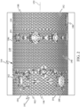
FIG. 2 is a schematic, plan view of the combustor liner of the gas turbine engine ofFIG. 1 , according to an exemplary embodiment; -
FIG. 3 is a schematic, fragmentary, cross sectional illustration of the intermediate hole area of the combustor liner ofFIG. 2 , according to an exemplary embodiment; -
FIG. 4 is a plan view of one cooling fin of the combustor ofFIG. 2 , according to an exemplary embodiment; -
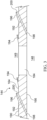
FIG. 5 is a sectional view taken generally through the line 5-5 ofFIG. 4 , in accordance with an exemplary embodiment; -
FIG. 6 is a fragmentary, plan view of one fin of the combustor liner ofFIG. 2 , according to an exemplary embodiment; and -
FIG. 7 is a schematic illustration of the additive manufacturing of a section of the combustor liner ofFIG. 2 , according to an exemplary embodiment. - The following detailed description is merely exemplary in nature and is not intended to limit the invention or the application and uses of the invention. As used herein, the word "exemplary" means "serving as an example, instance, or illustration." Thus, any embodiment described herein as "exemplary" is not necessarily to be construed as preferred or advantageous over other embodiments. All of the embodiments described herein are exemplary embodiments provided to enable persons skilled in the art to make or use the invention and not to limit the scope of the invention which is defined by the claims. Furthermore, there is no intention to be bound by any expressed or implied theory presented in the preceding technical field, background, brief summary, or the following detailed description.
- In this document, relational terms such as first and second, and the like may be used solely to distinguish one entity or action from another entity or action without necessarily requiring or implying any actual such relationship or order between such entities or actions. Numerical ordinals such as "first," "second," "third," etc. simply denote different singles of a plurality and do not imply any order or sequence unless specifically defined by the claim language. The sequence of the text in any of the claims does not imply that process steps must be performed in a temporal or logical order according to such sequence unless it is specifically defined by the language of the claim. The process steps may be interchanged in any order without departing from the scope of the invention as long as such an interchange does not contradict the claim language and is not logically nonsensical.
- Furthermore, depending on the context, words such as "connect" or "coupled to" used in describing a relationship between different elements do not imply that a direct physical connection must be made between these elements. For example, two elements may be connected to each other physically, electronically, logically, or in any other manner, through one or more additional elements.
- As used herein, the term "axial" refers to a direction that is generally parallel to or coincident with an axis of rotation, axis of symmetry, or centerline of a component or components. For example, in a cylinder or disc with a centerline and generally circular ends or opposing faces, the "axial" direction may refer to the direction that generally extends in parallel to the centerline between the opposite ends or faces. In certain instances, the term "axial" may be utilized with respect to components that are not cylindrical (or otherwise radially symmetric). For example, the "axial" direction for a rectangular housing containing a rotating shaft may be viewed as a direction that is generally parallel to or coincident with the rotational axis of the shaft. Furthermore, the term "radially" as used herein may refer to a direction or a relationship of components with respect to a line extending outward from a shared centerline, axis, or similar reference, for example in a plane of a cylinder or disc that is perpendicular to the centerline or axis. In certain instances, components may be viewed as "radially" aligned even though one or both of the components may not be cylindrical (or otherwise radially symmetric). Furthermore, the terms "axial" and "radial" (and any derivatives) may encompass directional relationships that are other than precisely aligned with (e.g., oblique to) the true axial and radial dimensions, provided the relationship is predominantly in the respective nominal axial or radial direction. As used herein, the term "substantially" denotes within 5% to account for manufacturing tolerances. Also, as used herein, the term "about" denotes within 5% to account for manufacturing tolerances.
- While at least one exemplary embodiment has been presented in the foregoing detailed description of the invention, it should be appreciated that a vast number of variations exist. It should also be appreciated that the exemplary embodiment or exemplary embodiments are only examples, and are not intended to limit the scope, applicability, or configuration of the invention in any way. Rather, the foregoing detailed description will provide those skilled in the art with a convenient road map for implementing an exemplary embodiment of the invention. It being understood that various changes may be made in the function and arrangement of elements described in an exemplary embodiment without departing from the scope of the invention as set forth in the appended claims.
- Referring to
FIG. 1 , a schematic, cross-sectional illustration of agas turbine engine 100 is depicted according to an exemplary embodiment. Thegas turbine engine 100 may be used in any of a variety of applications. Thegas turbine engine 100 may generally be contained in anengine case 110 and may include aninlet section 120, acompression section 130, acombustion section 140, aturbine section 150, and anexhaust section 160. The rotating parts of thegas turbine engine 100 rotate, such as on a shaft 154, about anaxis 172. - The inlet section may include a
fan 122, which draws in and accelerates at least a portion of the air directed to thecompression section 130. A fraction of the accelerated air from thefan 122 is directed through abypass section 170. The remaining fraction of air from thefan 122 is directed into thecompression section 130. Thecompression section 130 may include a series ofcompressors 132 that raise the pressure of the air received from theinlet section 120. Thecompressors 132 then direct the compressed air to thecombustion section 140. In thecombustion section 140, the high pressure air is mixed with injected fuel and combusted. Thecombustion section 140 includes acombustor 142 that, in the current embodiment, is generally formed from one substantially cylindrical and/orconical combustor liner 144 attached to adome 146. Air from thecompression section 130 is generally directed into thecombustor liner 144, which contains the combustion process in acombustion chamber 148. Some of the air from thecompression section 130 is directed around the outside of thecombustor liner 144 through apassage 149. After thecombustion section 140, the combusted air is directed into theturbine section 150, which includes a series ofturbines 152 to extract energy from the combusted air, which is then exhausted through theexhaust section 160. - Referring additionally to
FIG. 2 , thecombustor liner 144 is of a single-walled type. Thecombustor liner 144 has a number of air admission holes 162 that extend through thewall 190 of thecombustor liner 144 from itsouter surface 164 to its inner surface 166 (shown inFIG. 3 ). The air admission holes 162 allow air to move from thepassage 149 into thecombustion chamber 148 for combustion. The air admission holes 162 may include any ofprimary holes 180, intermediate (quench)holes 184 and dilution holes 186. Theprimary holes 180 provide the main/primary combustion air from thecompressors 132 and may be located in thedome 146, near theupstream end 182 of thecombustor liner 144 and/or may be configured as injector passages (not shown). This air is mixed with fuel, and then combusted. Intermediate air may be delivered into the combustion zone through a set of theintermediate holes 184 located downstream from theprimary holes 182 and part-way along thecombustor liner 144, such as about midway, to provide intermediate air to further complete the combustion processes, cooling the air down and diluting the gases. When further dilution is needed, dilution air may be provided into thecombustion chamber 148 through the dilution holes 186 in thecombustor liner 144 near thedownstream end 188 of thecombustion chamber 148 for any further combustion in a lean environment and/or to further cool the air before it reaches theturbine section 150. - Referring still to
FIGS. 1 and2 , and additionally toFIG. 3 , cooling air (air intended for cooling thecombustor liner 144 rather than combustion/dilution) is airflow that is injected through film cooling holes 192 in thecombustor liner 144 to generate a film layer of cool air at theinner surface 166 of thecombustor liner 144 as a barrier to combustion temperatures. The implementation of cooling air is configured so that it does not directly interact with the combustion air and process. The film cooling holes 192 are provided where cooling of thecombustor liner 144 is needed and are much smaller in size than the air admission holes 162 included in the combustor liner 144 (for example, an order of magnitude smaller). The air admission holes 162 may include theprimary holes 180, theintermediate holes 184 and/or the dilution holes 186 and may be formed as circular holes. The air admission holes 162 extend directly through thewall 190 of thecombustor liner 144 form theouter surface 164 to theinner surface 166, generally perpendicular to the axis 172 (shown inFIG. 2 ). The film cooling holes 192 are formed at shallow angles through thewall 190 of thecombustor liner 144 so that they extend through thewall 190 at an incline and over a longitudinal distance along theaxis 172. To effectively cool thewall 190, the film cooling holes 192 are positioned, to the extent practical, to provide complete coverage of hot areas of thecombustor liner 144. In embodiments, the film cooling holes 192 are configured as bellmouths, with a raised part of the wall (raised structure 196), resulting in mouth-like openings on the outside of thewall 190. Because of the raisedstructure 196, the layout of the film cooling holes 192 is designed to match the air flow around the outside of thecombustor liner 144 to maximize air entry and to avoid flow disturbances. - The film cooling holes 192 may be disposed, in particular, around the
intermediate holes 184 where temperatures in thecombustion chamber 148 are highest. The film cooling holes 192 are carefully located so that they do not intersect any of theintermediate holes 184 so as to not interfere with the airflow therethrough. As may be seen inFIG. 3 , theoutlet 198 of eachfilm cooling hole 192 is offset from itsinlet 200, meaning thefilm cooling hole 192 does not follow the shortest path through thewall 190 and theoutlet 198 is not directly across thewall 190 from theinlet 200. Because of the design of the film cooling holes 192 to match the airflow and to function properly, positioning them around theintermediate holes 184 is limited. For example, the film cooling holes 192 do not intersect theintermediate holes 184 and the raisedstructures 196 are not disposed at (are spaced away from) the edges of theintermediate holes 184. As a result, it has been found that providing complete coverage of thewall 190 in the areas around theintermediate holes 184 with the film cooling holes 192 is challenging and leads to areas of thewall 190 that are not covered by the film cooling holes 192. In these areas, the current embodiment includesfins 194 that project radially outward from theouter surface 164 of thewall 190. - In general, areas of the
wall 190 that will benefit from additional cooling and that are not covered by the film cooling holes 192 include thefins 194 on theouter surface 164 of thecombustor wall 190. Thefins 194 provide local heat extraction at any area where needed. This avoids the creation of hot spots that, due to the combustion process, might otherwise subject areas of thewall 190 to heat loads that may limit service life. The areas with thefins 194 may be defined on theouter surface 164 between theintermediate holes 184 and theinlets 200 of the film cooling holes 192. Being disposed on theouter surface 164, thefins 194 are exposed to air flowing through thepassage 149. Groupings of thefins 194 are generally disposed around each of theintermediate holes 184. For example, given the airflow around thecombustor liner 144, thefins 194 may be located in the wake area (downstream in the air flow direction) around theintermediate holes 184 where hot spots may otherwise form. The air moving through thepassage 149 has a tendency to flow both longitudinally and circumferentially around theouter surface 164 of thewall 190. Airflow characteristics including the wake areas may be identified during product development using commercially available fluid dynamics software and/or by performance testing. - As shown in plan view in
FIG. 4 and in sectional view inFIG. 5 , onecooling fin 194 includes amain body 210 that projects radially outward from theouter surface 164 of thecombustor liner 144. The main body has anopening 201 forming acavity 202. Thecavity 202 is a blind cavity with anend 203 so that thecavity 202 is open to thepassage 149 and is closed to thecombustion chamber 148. The definition of thefin 194 accommodates thecavity 202 which may include apocket 207 to help capture/trap particles, such as fine sand or other particles that are entrained in the air moving through thepassage 149 to alleviate occlusion ofcooling holes 192 near hot spots. Thefins 194 may be configured as shown inFIG. 4 or may be a mirror image with the version chosen for a particular position on thecombustor liner 144 determined based on print direction. Thefin 194 has a smooth fin outer profile that is aerodynamic to allow air flow without significant interference. Acontoured shape 204 of thefin 194 maximizes surface area for heat transfer to the air in thepassage 149. Thefin 194 includes anintegral fillet radius 205 around the periphery of themain body 210 to minimize stresses and enhance durability. The shape of thefin 194 is self-supporting for ease of fabrication by additive manufacturing. - Referring additionally to
FIG. 6 , where onfin 194 is shown in isolation, thefins 194 have an aerodynamic shape to match the airflow around the outside of thewall 190. The aerodynamic shape is designed to minimize disturbances to airflow caused by the projectingfins 194 and to avoid increasing local pressures. One desired result is that air approaching the air admission holes 162, such as theintermediate holes 184, is not disturbed prior to entry. In an embodiment, the aerodynamic shape may be an airfoil shape. Thefins 194 each have aleading end 206, a trailingend 208 and amain body 210. The profile of thefins 194 projecting from theouter surface 164 is contoured/rounded rather than extending away in a perpendicular direction placing thehighest part 212 of themain body 210 near the middle 214 of thefins 194. - In embodiments, the
combustor liner 144 may be manufactured by an additive manufacturing process such as laser powder bed printing. The aerodynamic shape of thefins 194 provides the added benefit that thefins 194 are self-supporting during the build process. For example,FIG. 7 shows onefin 194 in the build orientation during printing which proceeds in an upward direction inFIG. 7 as layers are built up. Theleading end 206 and the trailingend 208 are upward curving tapered elements in this orientation and are built on top of themain body 210 of thefin 194. In addition, forming with the highest part of thefin 194 from theouter surface 164 near the middle 214 of thefin 194 provides support. Printing of thefin 194 integral with thewall 190 starts at the bottom edge 216 (in the illustrated build orientation), and as the build of thefin 194 proceeds with thewall 190, the rounded fin profile angles outward relatively slowly to provide support for higher printed layers without an extreme cantilevered effect. - Accordingly, cooling fins are included on the outer surface of a combustor liner and are disposed in areas around air admission holes such as intermediate (quench) holes and/or in locations where adding through holes is not practical or feasible to the design of the combustor. The fins may be disposed between film cooling holes and the intermediate holes and are shaped to not disturb air flow around the outside of the combustor.
- While at least one exemplary embodiment has been presented in the foregoing detailed description of the invention, it should be appreciated that a vast number of variations exist. It should also be appreciated that the exemplary embodiment or exemplary embodiments are only examples, and are not intended to limit the scope, applicability, or configuration of the invention in any way. Rather, the foregoing detailed description will provide those skilled in the art with a convenient road map for implementing an exemplary embodiment of the invention. It being understood that various changes may be made in the function and arrangement of elements described in an exemplary embodiment without departing from the scope of the invention as set forth in the appended claims.
Claims (13)
- A combustor for a gas turbine engine, comprising:a combustor liner having a wall defining a combustion chamber, the wall having an inner surface facing the combustion chamber and an outer surface across the wall from the inner surface; andfins disposed on the outer surface,wherein the wall defines air admission holes that extend through the wall from the outer surface to the inner surface,wherein the wall defines film cooling holes that extend through the wall from the outer surface to the inner surface,wherein the fins are disposed in areas of the outer surface between the film cooling holes and the air admission holes.
- The combustor of claim 1, wherein the fins each have an aerodynamic shape.
- The combustor of claim 1, wherein groupings of the fins are disposed around individual air admission holes.
- The combustor of claim 1, wherein the film cooling holes are in-part each defined by a raised structure of the wall that extends from the outer surface and that is spaced away from the air admission holes, with the fins disposed between the raised structures and the air admission holes.
- The combustor is claim 1, wherein the wall comprises an additively manufactured structure with the fins integral with the wall.
- The combustor of claim 1, wherein the fins each have an aerodynamic shape configured to align with an airflow around the combustor liner and to avoid disturbing a part of the airflow entering the air admission holes.
- The combustor of claim 1, wherein the fins are disposed in groups next to each other, and adjacent the air admission holes.
- The combustor of claim 1, wherein the air admission holes comprise quench holes configured to provide air substantially midway along the combustor liner to complete combustion.
- The combustor of claim 1, comprising an air passage defined around the combustor liner, wherein the combustor liner comprises a single-walled structure defining the combustion chamber with the wall exposed to both combustion in the combustion chamber and air in the air passage.
- The combustor of claim 1, wherein the fins are formed as solid structures integral with the wall without through holes.
- The combustor of claim 1, wherein the fins have an airfoil shape with a leading end, a trailing end, and a main body between the leading end and the trailing end, with a profile of the fins projecting from the outer surface and being contoured to match an airflow along the outer surface of the wall, the fins configured to avoid the film cooling holes and to direct entry of air into the air admission holes to facilitate air into the combustion chamber.
- The combustor of claim 1, wherein groupings of the fins are disposed around individual holes of the air admission holes, the groupings disposed between each respective individual hole of the individual holes and the film cooling holes only, meaning each one of the groupings of the fins is disposed around the respective individual hole and the air admission holes surround the respective individual hole and the each one of the groupings of the fins and the fins are not disposed on other areas of the combustor liner, where the other areas are not between each respective individual hole of the individual holes and the film cooling holes.
- The combustor of claim 1, wherein the air admission holes are configured to allow air to move into the combustion chamber for combustion, wherein the film cooling holes are configured to generate a film layer of cool air inside the combustor liner and are disposed at an angle through the wall, wherein the air admission holes are substantially larger than the film cooling holes.
Applications Claiming Priority (1)
| Application Number | Priority Date | Filing Date | Title |
|---|---|---|---|
| US18/313,578 US12085279B1 (en) | 2023-05-08 | 2023-05-08 | Gas turbine combustor with enhanced cooling features |
Publications (1)
| Publication Number | Publication Date |
|---|---|
| EP4462025A1 true EP4462025A1 (en) | 2024-11-13 |
Family
ID=89941171
Family Applications (1)
| Application Number | Title | Priority Date | Filing Date |
|---|---|---|---|
| EP24157368.2A Pending EP4462025A1 (en) | 2023-05-08 | 2024-02-13 | Gas turbine combustor with enhanced cooling features |
Country Status (2)
| Country | Link |
|---|---|
| US (1) | US12085279B1 (en) |
| EP (1) | EP4462025A1 (en) |
Families Citing this family (1)
| Publication number | Priority date | Publication date | Assignee | Title |
|---|---|---|---|---|
| JP2025117172A (en) * | 2024-01-30 | 2025-08-12 | 本田技研工業株式会社 | Gas turbine combustor |
Citations (7)
| Publication number | Priority date | Publication date | Assignee | Title |
|---|---|---|---|---|
| US3777484A (en) * | 1971-12-08 | 1973-12-11 | Gen Electric | Shrouded combustion liner |
| EP1098141A1 (en) * | 1999-11-06 | 2001-05-09 | Rolls-Royce Plc | Wall elements for gas turbine engine combustors |
| US20050034399A1 (en) * | 2002-01-15 | 2005-02-17 | Rolls-Royce Plc | Double wall combustor tile arrangement |
| US20050047932A1 (en) * | 2003-08-14 | 2005-03-03 | Tomoyoshi Nakae | Heat exchanging wall, gas turbine using the same, and flying body with gas turbine engine |
| US20100186416A1 (en) * | 2009-01-27 | 2010-07-29 | General Electric Company | Flow conditioner for use in gas turbine component in which combustion occurs |
| US20170089580A1 (en) * | 2015-09-28 | 2017-03-30 | Pratt & Whitney Canada Corp. | Single skin combustor with heat transfer enhancement |
| US20190017440A1 (en) * | 2017-07-17 | 2019-01-17 | United Technologies Corporation | Combustor panel standoffs with cooling holes |
Family Cites Families (7)
| Publication number | Priority date | Publication date | Assignee | Title |
|---|---|---|---|---|
| US20020066273A1 (en) | 2000-12-04 | 2002-06-06 | Mitsubishi Heavy Industries, Ltd. | Plate fin and combustor using the plate fin |
| EP2999927B1 (en) * | 2013-05-23 | 2020-01-08 | United Technologies Corporation | Gas turbine engine combustor liner panel |
| US10655540B2 (en) | 2016-09-30 | 2020-05-19 | General Electric Company | Apparatus and systems for a surface cooler having pliant fins |
| KR102080567B1 (en) | 2018-01-03 | 2020-02-24 | 두산중공업 주식회사 | Cooling structure of combustor, combustor and gas turbine having the same |
| US11085641B2 (en) * | 2018-11-27 | 2021-08-10 | Honeywell International Inc. | Plug resistant effusion holes for gas turbine engine |
| US11480337B2 (en) | 2019-11-26 | 2022-10-25 | Collins Engine Nozzles, Inc. | Fuel injection for integral combustor and turbine vane |
| US11434772B2 (en) | 2020-09-29 | 2022-09-06 | General Electric Company | Turbine nozzle and method of manufacture |
-
2023
- 2023-05-08 US US18/313,578 patent/US12085279B1/en active Active
-
2024
- 2024-02-13 EP EP24157368.2A patent/EP4462025A1/en active Pending
Patent Citations (7)
| Publication number | Priority date | Publication date | Assignee | Title |
|---|---|---|---|---|
| US3777484A (en) * | 1971-12-08 | 1973-12-11 | Gen Electric | Shrouded combustion liner |
| EP1098141A1 (en) * | 1999-11-06 | 2001-05-09 | Rolls-Royce Plc | Wall elements for gas turbine engine combustors |
| US20050034399A1 (en) * | 2002-01-15 | 2005-02-17 | Rolls-Royce Plc | Double wall combustor tile arrangement |
| US20050047932A1 (en) * | 2003-08-14 | 2005-03-03 | Tomoyoshi Nakae | Heat exchanging wall, gas turbine using the same, and flying body with gas turbine engine |
| US20100186416A1 (en) * | 2009-01-27 | 2010-07-29 | General Electric Company | Flow conditioner for use in gas turbine component in which combustion occurs |
| US20170089580A1 (en) * | 2015-09-28 | 2017-03-30 | Pratt & Whitney Canada Corp. | Single skin combustor with heat transfer enhancement |
| US20190017440A1 (en) * | 2017-07-17 | 2019-01-17 | United Technologies Corporation | Combustor panel standoffs with cooling holes |
Also Published As
| Publication number | Publication date |
|---|---|
| US12085279B1 (en) | 2024-09-10 |
Similar Documents
| Publication | Publication Date | Title |
|---|---|---|
| US11519604B2 (en) | Plug resistant effusion holes for gas turbine engine | |
| US7114339B2 (en) | Cavity on-board injection for leakage flows | |
| US8529193B2 (en) | Gas turbine engine components with improved film cooling | |
| EP3745027B1 (en) | Gas turbine engine component with effusion cooling holes | |
| US8707712B2 (en) | Gas turbine engine turbine vane airfoil profile | |
| US10443398B2 (en) | Turbine blade | |
| US10815789B2 (en) | Impingement holes for a turbine engine component | |
| US11029027B2 (en) | Dilution/effusion hole pattern for thick combustor panels | |
| US11767766B1 (en) | Turbomachine airfoil having impingement cooling passages | |
| US20180156044A1 (en) | Engine component with flow enhancer | |
| US12085279B1 (en) | Gas turbine combustor with enhanced cooling features | |
| EP3643968B1 (en) | Gas turbine engine dual-wall hot section structure | |
| US20180363466A1 (en) | Turbine engine component with deflector | |
| US10808547B2 (en) | Turbine engine airfoil with cooling | |
| US20150159513A1 (en) | Bi-cast turbine nozzles and methods for cooling slip joints therein | |
| CN108999647B (en) | Turbomachine rotor blade | |
| US10690345B2 (en) | Combustor assemblies for use in turbine engines and methods of assembling same | |
| US11629601B2 (en) | Turbomachine rotor blade with a cooling circuit having an offset rib | |
| US10808572B2 (en) | Cooling structure for a turbomachinery component | |
| US20250243766A1 (en) | Polymer-metal composite stator vanes and methods for manufacturing the same | |
| US12188373B1 (en) | Cooling circuit for a platform of a stator vane assembly | |
| US10364685B2 (en) | Impingement system for an airfoil | |
| US20200217208A1 (en) | Gas turbine engine component with discharge slot having a flared base |
Legal Events
| Date | Code | Title | Description |
|---|---|---|---|
| PUAI | Public reference made under article 153(3) epc to a published international application that has entered the european phase |
Free format text: ORIGINAL CODE: 0009012 |
|
| STAA | Information on the status of an ep patent application or granted ep patent |
Free format text: STATUS: THE APPLICATION HAS BEEN PUBLISHED |
|
| AK | Designated contracting states |
Kind code of ref document: A1 Designated state(s): AL AT BE BG CH CY CZ DE DK EE ES FI FR GB GR HR HU IE IS IT LI LT LU LV MC ME MK MT NL NO PL PT RO RS SE SI SK SM TR |
|
| STAA | Information on the status of an ep patent application or granted ep patent |
Free format text: STATUS: REQUEST FOR EXAMINATION WAS MADE |
|
| 17P | Request for examination filed |
Effective date: 20250424 |