EP4462001A1 - Flange coupling system for connecting pipes in an aircraft - Google Patents
Flange coupling system for connecting pipes in an aircraft Download PDFInfo
- Publication number
- EP4462001A1 EP4462001A1 EP23172631.6A EP23172631A EP4462001A1 EP 4462001 A1 EP4462001 A1 EP 4462001A1 EP 23172631 A EP23172631 A EP 23172631A EP 4462001 A1 EP4462001 A1 EP 4462001A1
- Authority
- EP
- European Patent Office
- Prior art keywords
- flange
- ring
- flange element
- coupling system
- fixation
- Prior art date
- Legal status (The legal status is an assumption and is not a legal conclusion. Google has not performed a legal analysis and makes no representation as to the accuracy of the status listed.)
- Pending
Links
Images


Classifications
-
- F—MECHANICAL ENGINEERING; LIGHTING; HEATING; WEAPONS; BLASTING
- F16—ENGINEERING ELEMENTS AND UNITS; GENERAL MEASURES FOR PRODUCING AND MAINTAINING EFFECTIVE FUNCTIONING OF MACHINES OR INSTALLATIONS; THERMAL INSULATION IN GENERAL
- F16L—PIPES; JOINTS OR FITTINGS FOR PIPES; SUPPORTS FOR PIPES, CABLES OR PROTECTIVE TUBING; MEANS FOR THERMAL INSULATION IN GENERAL
- F16L23/00—Flanged joints
- F16L23/02—Flanged joints the flanges being connected by members tensioned axially
- F16L23/036—Flanged joints the flanges being connected by members tensioned axially characterised by the tensioning members, e.g. specially adapted bolts or C-clamps
-
- F—MECHANICAL ENGINEERING; LIGHTING; HEATING; WEAPONS; BLASTING
- F16—ENGINEERING ELEMENTS AND UNITS; GENERAL MEASURES FOR PRODUCING AND MAINTAINING EFFECTIVE FUNCTIONING OF MACHINES OR INSTALLATIONS; THERMAL INSULATION IN GENERAL
- F16L—PIPES; JOINTS OR FITTINGS FOR PIPES; SUPPORTS FOR PIPES, CABLES OR PROTECTIVE TUBING; MEANS FOR THERMAL INSULATION IN GENERAL
- F16L39/00—Joints or fittings for double-walled or multi-channel pipes or pipe assemblies
-
- F—MECHANICAL ENGINEERING; LIGHTING; HEATING; WEAPONS; BLASTING
- F16—ENGINEERING ELEMENTS AND UNITS; GENERAL MEASURES FOR PRODUCING AND MAINTAINING EFFECTIVE FUNCTIONING OF MACHINES OR INSTALLATIONS; THERMAL INSULATION IN GENERAL
- F16L—PIPES; JOINTS OR FITTINGS FOR PIPES; SUPPORTS FOR PIPES, CABLES OR PROTECTIVE TUBING; MEANS FOR THERMAL INSULATION IN GENERAL
- F16L23/00—Flanged joints
- F16L23/02—Flanged joints the flanges being connected by members tensioned axially
- F16L23/032—Flanged joints the flanges being connected by members tensioned axially characterised by the shape or composition of the flanges
-
- F—MECHANICAL ENGINEERING; LIGHTING; HEATING; WEAPONS; BLASTING
- F16—ENGINEERING ELEMENTS AND UNITS; GENERAL MEASURES FOR PRODUCING AND MAINTAINING EFFECTIVE FUNCTIONING OF MACHINES OR INSTALLATIONS; THERMAL INSULATION IN GENERAL
- F16L—PIPES; JOINTS OR FITTINGS FOR PIPES; SUPPORTS FOR PIPES, CABLES OR PROTECTIVE TUBING; MEANS FOR THERMAL INSULATION IN GENERAL
- F16L39/00—Joints or fittings for double-walled or multi-channel pipes or pipe assemblies
- F16L39/005—Joints or fittings for double-walled or multi-channel pipes or pipe assemblies for concentric pipes
Definitions
- the invention relates to a flange coupling system for connecting pipes in an aircraft. Further, the invention relates to an aircraft comprising a flange coupling system.
- the invention supports the installation of hydrogen systems on an aircraft.
- the invention can be used as well for pipe or line systems transporting other mediums.
- the invention is suitable for venting systems and/or gaseous distribution systems in an aircraft.
- the invention can be applied particularly for the connection of single pipe segments within a double walled piping system.
- Figure 3 shows an example of a flange connection 100 according to the state of the art. It comprises two flanges 101, 102 which are connected to each other by bolts 103. The flanges are pressed against each other in a sealing and clamping plane 104 where a sealing ring 105 is provided between the flanges 101, 102.
- Such a conventional flange connection has a relatively large diameter which requires a large installation space.
- a huge coupling in terms of diameter for the inner line or pipe leads to a large diameter of the outer line of the double walled pipe assembly.
- the weight is increased which leads to an increased fuel consumption of the aircraft.
- the invention provides a flange coupling system for connecting pipes in an aircraft, comprising: a first flange element and a second flange element, each flange element comprising a flange ring surrounding an opening for transporting a liquid or gaseous medium, wherein each flange ring comprises a sealing surface for mutual connection of both flange elements, wherein each flange element comprises one or more fixation members configured for mutual fixation of both flange elements so that their sealing surfaces are pressed against each other in a sealing plane, wherein the fixation members of both flange elements are arranged in a way that both flange elements are fixed to each other in a coupling plane which is located away from the sealing plane.
- the fixation members of the first flange element comprise claws distributed around the sealing surface and extending from the first flange element over the flange ring of the first flange element and over the flange ring of the second flange element when both flange elements are mutually connected.
- each fixation member of the first flange element comprises a front end which is configured as a fastener for a bolt provided for fixing the fixation member of the second flange element to the fixation member of the first flange element in the fixation plane.
- the fixation member of the second flange element comprises a tension ring spaced away from its flange ring which provides the sealing plane, wherein the tension ring is configured for being fastened to the fixation members of the first flange element.
- the fixation members of the first flange element are formed to reach behind the flange ring of the second flange element and to be pulled towards the tension ring when both flange elements are being coupled to each other.
- the fixation member of the second flange element comprises a number of through holes for holding the bolts when they are fixed to the ends of the fixation members of the first flange element.
- the fixation members of the first flange element comprise nuts for fastening the bolts.
- fixation members of the first flange element are pivotable about an axis tangential to its flange ring, and/or moveable towards its sealing surface.
- the flange ring of the first flange element comprises a ring groove formed at the opposite side of its sealing surface to receive protrusions of the fixation members of the first flange element for holding them in position when both flange elements are being coupled.
- the first flange element comprises claw attachment means for the fixation members, wherein preferably the fixation members are configured to transfer loads across at least the flange ring, and preferably the attachment means are configured to hold the fixation members in place without any load transfer.
- the flange coupling system is configured for connecting pipe segments within a double walled piping system.
- the invention provides an aircraft, comprising a flange coupling system according to the invention.
- the invention achieves that the flange coupling is more compact and has a reduced weight.
- the diameter of the coupling is reduced due to the more compact design of the flange connection. This is achieved by the separation of the two functions sealing and coupling from one plane to two separate planes.
- a double walled pipe assembly having an outer line or pipe with a reduced diameter can be provided by coupling its inner line or pipe with the flange coupling system according to the invention.
- Figures 1 and 2 show a flange coupling system 10 according to a preferred embodiment of the invention. It comprises a first flange element 11 and a second flange element 12 which are configured for being connected to each other.
- the first flange element 11 comprises a disc-shaped flange ring 13 which surrounds an opening 14 for transporting a liquid or gaseous medium.
- the second flange element 12 comprises a second disc shaped flange ring 15 surrounding an opening 16 for transporting the liquid or gaseous medium.
- Each flange ring 13, 15 comprises a sealing surface 17 for mutual connection of both flange elements 11, 12.
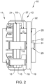
- Each flange element 11, 12 comprises one or more fixation members 18, 19 which are configured for mutual fixation of both flange elements 11, 12 so that their sealing surfaces 17 are pressed against each other in a sealing plane 21 (see figure 2 ).
- the sealing plane 21 is formed by the mutually connected sealing surfaces 17 of both flange elements 11, 12.
- fixation members 18, 19 of both flange elements 11, 12 are arranged in a way that both flange elements 11, 12 are fixed to each other in a coupling plane 22 which is located away from the sealing plane 21 (see figure 2 ).
- a sealing formed as a sealing ring 23 is provided in the sealing surface 17 of the second flange element 12. It may also be provided in the sealing surface 17 of the first flange element 11 or in the sealing surface 17 of both flange elements 11, 12.
- the sealing 23 or gasket has an O-shaped cross section. But it may also have another cross section, like e.g. a C-shaped cross section.
- the sealing 23 is positioned in a ring-shaped groove formed in the sealing surface 17 of the respective flange element 11 and/or 12.
- Both sealing surfaces 17 form a circular area which provides the sealing plane 21 when both flange elements 11, 12 are interconnected with their sealing surfaces 17.
- the fixation members 18 of the first flange element 11 are designed as or comprise a number of claws 18 which are distributed around the sealing surface 17 and extending from the first flange element 11 over its flange ring 13 and over the flange ring 15 of the second flange element 12 when both flange elements 11, 12 are mutually connected.
- the claws 18 are arranged circumferentially on the outer side 24 of first flange element 11.
- they are arranged at equal distances to provide an equal distribution of forces for pressing the sealing surfaces 17 of both flange elements 11, 12 against each other.
- Each claw 18 comprises a front end 25 which is configured as a fastener for a bolt 26 provided for fixing the fixation member 19 of the second flange element 12 to the respective claws 18 of the first flange element 11 in the fixation plane 22.
- a square nut 27 is arranged in the front end 25 of each claw 18 for receiving a threaded front portion of bolt 26.
- the fixation member 19 of second flange element 12 is formed as a tension ring which is arranged on the outer side 28 of second flange element 12, or more specifically of a pipe section 37 of flange element 12.
- the fixation member or tension ring 19 surrounds second flange element 12, being at a distance D from the flange ring 15 of second flange 12 which provides at its front side the sealing surface 17. That means that the tension ring 19 is spaced away from flange ring 15 which provides at its sealing surface 17 the sealing plane 21.
- the tension ring 19 is configured for being fastened to the claws 18 of first flange element 11.
- a number of through holes 29 are provided in tension ring 19 for holding the bolts 26 when they are screwed into the nuts 27 provided in the front end 25 of claws 18, so that the claws 18 are pulled to tension ring 19 when both flange elements 11, 12 are being coupled to each other by tightening the bolts 26.
- the claws 18 are formed to reach behind flange ring 15 of second flange element 12 and to be pulled towards the tension ring 19 when both flange elements 11, 12 are being coupled to each other.
- the claws 18 are comprising or are formed as straight arms 30 which extend flat across the flange rings 13, 15 which provide the contact surfaces 17 for mutual connection of both flange elements 11, 12.
- Each arm 30 comprises an angled end portion which forms front end 25, so that each claw 18 reaches with its front end 25 behind the flange ring 15 of second flange element 12.
- the angled front ends 25 of claws 18 are positioned between flange ring 15 of the first flange element 11 and tension ring 19 of the second flange element 12 when both flange elements 11, 12 are coupled and fixed to each other by screwing the bolts 26 into nuts 27.
- Each claw 18 is movable mounted in attachment means 33 which are circumferentially provided on the outer side 24 of first flange element 11. More specifically, the attachment means 33 are circumferentially provided on the outer side 24 of a pipe section 34 of flange element 11.
- the claws 18 are pivotable mounted in attachment means 33 so that they can be opened for attaching the second flange element 12 to the first element 11 at the contact or sealing surfaces 17, and can be closed for fixing the front ends 25 to bolts 26 which are held in tension ring 19.
- attachment means 33 are configured to allow a movement of the respective claw 18 towards flange ring 13. By this movement, a protrusion 35 of claw 18 is engaged with a groove 36 provided on the backside of flange ring 13. This has the function to hold the claws 18 in position.
- the clamping force will not be applied directly on the sealing plane 21. Instead, it is applied on the tension ring 19 which is located away from the sealing plane 21.
- the load is transferred from the backside 32 of tension ring 19 via the bolts 26 and the claws 18 to flange 11 which comprises the claw attachment means 33.
- the claws 18 transfer the loads from their front ends 25 across both flange rings 15, 13 behind flange ring 13 by using a tongue and groove principle (e.g. reference signs 35 and 36).
- the attachment means 33 have no primary load transfer purpose. Rather, their function is to hold the claws 18 in place and enable an easier assembling.
- the flange coupling system 10 is configured for connecting pipe segments within a double walled piping system.
- inner pipe segments within a double walled piping system are connected by the flange coupling system 10.
- the flange coupling system 10 is in particular used in an aircraft, preferably in a hydrogen system of the aircraft.
Landscapes
- Engineering & Computer Science (AREA)
- General Engineering & Computer Science (AREA)
- Mechanical Engineering (AREA)
- Flanged Joints, Insulating Joints, And Other Joints (AREA)
Abstract
Description
- The invention relates to a flange coupling system for connecting pipes in an aircraft. Further, the invention relates to an aircraft comprising a flange coupling system.
- In particular, the invention supports the installation of hydrogen systems on an aircraft. The invention can be used as well for pipe or line systems transporting other mediums. Moreover, the invention is suitable for venting systems and/or gaseous distribution systems in an aircraft. The invention can be applied particularly for the connection of single pipe segments within a double walled piping system.
-
Figure 3 shows an example of aflange connection 100 according to the state of the art. It comprises twoflanges bolts 103. The flanges are pressed against each other in a sealing and clampingplane 104 where a sealing ring 105 is provided between theflanges - Such a conventional flange connection has a relatively large diameter which requires a large installation space. In particular in a double walled pipe assembly necessary in an aircraft, a huge coupling in terms of diameter for the inner line or pipe leads to a large diameter of the outer line of the double walled pipe assembly. Besides the problem, that a large installation space is needed for such conventional couplings, the weight is increased which leads to an increased fuel consumption of the aircraft.
- It is the objective of the invention to provide a flange coupling for connecting pipes in an aircraft, which needs less installation space and which has a reduced weight.
- The object is achieved by the subject matter according to claim one. Advantageous embodiments are subject matter of the dependent claims.
- According to a first aspect, the invention provides a flange coupling system for connecting pipes in an aircraft, comprising: a first flange element and a second flange element, each flange element comprising a flange ring surrounding an opening for transporting a liquid or gaseous medium, wherein each flange ring comprises a sealing surface for mutual connection of both flange elements, wherein each flange element comprises one or more fixation members configured for mutual fixation of both flange elements so that their sealing surfaces are pressed against each other in a sealing plane, wherein the fixation members of both flange elements are arranged in a way that both flange elements are fixed to each other in a coupling plane which is located away from the sealing plane.
- Preferably, the fixation members of the first flange element comprise claws distributed around the sealing surface and extending from the first flange element over the flange ring of the first flange element and over the flange ring of the second flange element when both flange elements are mutually connected.
- Preferably, each fixation member of the first flange element comprises a front end which is configured as a fastener for a bolt provided for fixing the fixation member of the second flange element to the fixation member of the first flange element in the fixation plane.
- Preferably, the fixation member of the second flange element comprises a tension ring spaced away from its flange ring which provides the sealing plane, wherein the tension ring is configured for being fastened to the fixation members of the first flange element.
- Preferably, the fixation members of the first flange element are formed to reach behind the flange ring of the second flange element and to be pulled towards the tension ring when both flange elements are being coupled to each other.
- Preferably, the fixation member of the second flange element comprises a number of through holes for holding the bolts when they are fixed to the ends of the fixation members of the first flange element.
- Preferably, the fixation members of the first flange element comprise nuts for fastening the bolts.
- Preferably, the fixation members of the first flange element are pivotable about an axis tangential to its flange ring, and/or moveable towards its sealing surface.
- Preferably, the flange ring of the first flange element comprises a ring groove formed at the opposite side of its sealing surface to receive protrusions of the fixation members of the first flange element for holding them in position when both flange elements are being coupled.
- Preferably, the first flange element comprises claw attachment means for the fixation members, wherein preferably the fixation members are configured to transfer loads across at least the flange ring, and preferably the attachment means are configured to hold the fixation members in place without any load transfer.
- Preferably, the flange coupling system is configured for connecting pipe segments within a double walled piping system.
- According to a second aspect, the invention provides an aircraft, comprising a flange coupling system according to the invention.
- The invention achieves that the flange coupling is more compact and has a reduced weight. In particular, the diameter of the coupling is reduced due to the more compact design of the flange connection. This is achieved by the separation of the two functions sealing and coupling from one plane to two separate planes.
- In particular, a double walled pipe assembly having an outer line or pipe with a reduced diameter can be provided by coupling its inner line or pipe with the flange coupling system according to the invention.
- Since a reduced outer line diameter of a double walled piping system is achieved by the invention, the forces due to pressure acting on the circular contact area of the mutually connected flanges are reduced. This results in weight reduction plus an additional weight reduction due to the smaller geometry of the flange coupling system. Thus, two levers of weight reduction are achieved by the invention.
- A preferred embodiment of the invention is described in more detail with reference to the accompanying drawings, in which
- Fig. 1
- depicts a perspective view of a flange coupling system according to a preferred embodiment of the invention;
- Fig. 2
- depicts a side view of the flange coupling system when it's flange elements are connected; and
- Fig. 3
- depicts a schematic sectional view of a conventional flange according to the state of the art.
-
Figures 1 and2 show aflange coupling system 10 according to a preferred embodiment of the invention. It comprises afirst flange element 11 and asecond flange element 12 which are configured for being connected to each other. Thefirst flange element 11 comprises a disc-shaped flange ring 13 which surrounds anopening 14 for transporting a liquid or gaseous medium. Similarly, thesecond flange element 12 comprises a second disc shapedflange ring 15 surrounding anopening 16 for transporting the liquid or gaseous medium. Eachflange ring flange elements - Each
flange element more fixation members flange elements figure 2 ). Thesealing plane 21 is formed by the mutually connected sealing surfaces 17 of bothflange elements - The
fixation members flange elements flange elements coupling plane 22 which is located away from the sealing plane 21 (seefigure 2 ). - As depicted in
Fig. 1 , a sealing formed as asealing ring 23 is provided in the sealing surface 17 of thesecond flange element 12. It may also be provided in the sealing surface 17 of thefirst flange element 11 or in the sealing surface 17 of bothflange elements sealing 23 is positioned in a ring-shaped groove formed in the sealing surface 17 of therespective flange element 11 and/or 12. - Both sealing surfaces 17 form a circular area which provides the
sealing plane 21 when bothflange elements - The
fixation members 18 of thefirst flange element 11 are designed as or comprise a number ofclaws 18 which are distributed around the sealing surface 17 and extending from thefirst flange element 11 over itsflange ring 13 and over theflange ring 15 of thesecond flange element 12 when bothflange elements - The
claws 18 are arranged circumferentially on theouter side 24 offirst flange element 11. Advantageously, they are arranged at equal distances to provide an equal distribution of forces for pressing the sealing surfaces 17 of bothflange elements - Each
claw 18 comprises afront end 25 which is configured as a fastener for abolt 26 provided for fixing thefixation member 19 of thesecond flange element 12 to therespective claws 18 of thefirst flange element 11 in thefixation plane 22. - For this purpose, a
square nut 27 is arranged in thefront end 25 of eachclaw 18 for receiving a threaded front portion ofbolt 26. - The
fixation member 19 ofsecond flange element 12 is formed as a tension ring which is arranged on theouter side 28 ofsecond flange element 12, or more specifically of apipe section 37 offlange element 12. The fixation member ortension ring 19 surroundssecond flange element 12, being at a distance D from theflange ring 15 ofsecond flange 12 which provides at its front side the sealing surface 17. That means that thetension ring 19 is spaced away fromflange ring 15 which provides at its sealing surface 17 thesealing plane 21. - The
tension ring 19 is configured for being fastened to theclaws 18 offirst flange element 11. For this purpose, a number of throughholes 29 are provided intension ring 19 for holding thebolts 26 when they are screwed into thenuts 27 provided in thefront end 25 ofclaws 18, so that theclaws 18 are pulled totension ring 19 when bothflange elements bolts 26. - The
claws 18 are formed to reach behindflange ring 15 ofsecond flange element 12 and to be pulled towards thetension ring 19 when bothflange elements - Advantageously, the
claws 18 are comprising or are formed asstraight arms 30 which extend flat across the flange rings 13, 15 which provide the contact surfaces 17 for mutual connection of bothflange elements arm 30 comprises an angled end portion which formsfront end 25, so that eachclaw 18 reaches with itsfront end 25 behind theflange ring 15 ofsecond flange element 12. In this way, the angled front ends 25 ofclaws 18 are positioned betweenflange ring 15 of thefirst flange element 11 andtension ring 19 of thesecond flange element 12 when bothflange elements bolts 26 into nuts 27. - When the bolts or screws 26 are tightened, the
claws 18 are pulled towardstension ring 19 while the bolt heads 31 ofbolts 26 are pressed againstbackside 32 oftension ring 19, which forms in this way the clamping orcoupling plane 22 when bothflanges - Each
claw 18 is movable mounted in attachment means 33 which are circumferentially provided on theouter side 24 offirst flange element 11. More specifically, the attachment means 33 are circumferentially provided on theouter side 24 of a pipe section 34 offlange element 11. - The
claws 18 are pivotable mounted in attachment means 33 so that they can be opened for attaching thesecond flange element 12 to thefirst element 11 at the contact or sealing surfaces 17, and can be closed for fixing the front ends 25 tobolts 26 which are held intension ring 19. - In addition, the attachment means 33 are configured to allow a movement of the
respective claw 18 towardsflange ring 13. By this movement, aprotrusion 35 ofclaw 18 is engaged with agroove 36 provided on the backside offlange ring 13. This has the function to hold theclaws 18 in position. - As described above, the clamping force will not be applied directly on the sealing
plane 21. Instead, it is applied on thetension ring 19 which is located away from the sealingplane 21. When thebolts 26 are tightened, the load is transferred from thebackside 32 oftension ring 19 via thebolts 26 and theclaws 18 to flange 11 which comprises the claw attachment means 33. Theclaws 18 transfer the loads from their front ends 25 across both flange rings 15, 13 behindflange ring 13 by using a tongue and groove principle (e.g.reference signs 35 and 36). The attachment means 33 have no primary load transfer purpose. Rather, their function is to hold theclaws 18 in place and enable an easier assembling. - In particular, the
flange coupling system 10 is configured for connecting pipe segments within a double walled piping system. Advantageously, inner pipe segments within a double walled piping system are connected by theflange coupling system 10. - The
flange coupling system 10 is in particular used in an aircraft, preferably in a hydrogen system of the aircraft. -
- 10
- coupling system
- 11
- first flange element
- 12
- second flange element
- 13
- flange ring of first flange element
- 14
- opening
- 15
-
flange ring 15 of second flange element - 16
- opening
- 17
- sealing surfaces
- 18
- fixation members of first flange element / claws
- 19
- fixation member of second flange element / tension ring
- 21
- sealing plane
- 22
- coupling plane
- 23
- sealing ring
- 24
- outer side of first flange element
- 25
- front end of claw
- 26
- bolt
- 27
- nuts
- 28
- outer side of second flange element
- 29
- through holes
- 30
- arms of claws
- 31
- bolt heads
- 32
- backside of tension ring
- 33
- attachment means
- 34
- pipe section of first flange element
- 35
- protrusion of claw
- 36
- groove
- 37
- pipe section of second flange element
- D
- Distance
Claims (12)
- Flange coupling system for connecting pipes in an aircraft, comprising:a first flange element (11) and a second flange element (12),each flange element (11, 12) comprising a flange ring (13, 15) surrounding an opening (16) for transporting a liquid or gaseous medium,wherein each flange ring (13, 15) comprises a sealing surface (17) for mutual connection of both flange elements (11, 12),wherein each flange element (11, 12) comprises one or more fixation members (18, 19) configured for mutual fixation of both flange elements (11, 12) so that their sealing surfaces (17) are pressed against each other in a sealing plane (21),wherein the fixation members (18, 19) of both flange elements (11, 12) are arranged in a way that both flange elements (11, 12) are fixed to each other in a fixation plane (22) which is located away from the sealing plane (21).
- Flange coupling system according to claim 1, characterized in that the fixation members (18) of the first flange element (11) comprise claws distributed around the sealing surface (17) and extending from the first flange element (11) over the flange ring (13) of the first flange element (11) and over the flange ring (15) of the second flange element (12) when both flange elements (11, 12) are mutually connected.
- Flange coupling system according to claim 1 or 2, characterized in that each fixation member (18) of the first flange element (11) comprises a front end (25) which is configured as a fastener for a bolt (26) provided for fixing the fixation member (19) of the second flange element (12) to the fixation member (18) of the first flange element (11) in the fixation plane (22).
- Flange coupling system according to one of the preceding claims, characterized in that the fixation member (19) of the second flange element (12) comprises or is formed as a tension ring spaced away from its flange ring (15) which provides the sealing plane (21), wherein the tension ring is configured for being fastened to the fixation members (18) of the first flange element (11).
- Flange coupling system according to claim 4, characterized in that the fixation members (18) of the first flange element (11) are formed to reach behind the flange ring (15) of the second flange element (12) and to be pulled towards the tension ring (19) when both flange elements (11, 12) are being coupled to each other.
- Flange coupling system according to any of claims 3 to 5, characterized in that the fixation member (19) of the second flange element (12) comprises a number of through holes (29) for holding the bolts (26) when they are fixed to the ends (25) of the fixation members (18) of the first flange element (11).
- Flange coupling system according to any of claims 3 to 6, characterized in that the fixation members (18) of the first flange element (11) comprise nuts (27) for fastening the bolts (26).
- Flange coupling system according to any of the preceding claims, characterized in that the fixation members (18) of the first flange element (11) are8.1. pivotable about an axis tangential to its flange ring (13), and/or8.2. moveable towards its sealing surface (17).
- Flange coupling system according to any of the preceding claims, characterized in that the flange ring (13) of the first flange element (11) comprises a groove (36) formed at the opposite side of its sealing surface (17) to receive protrusions (35) provided by the fixation members (18) of the first flange element (11) for holding them in position when both flange elements (11, 12) are being coupled.
- Flange coupling system according to claim 9, characterized in that the first flange element (11) comprises claw attachment means (33) for the fixation members (18), wherein the fixation members (18) are configured to transfer loads across at least the flange ring (13), and the attachment means (33) are configured to hold the fixation members (18) in place without any load transfer.
- Flange coupling system according to any of the preceding claims, characterized in that it is configured for connecting pipe segments within a double walled piping system.
- Aircraft, comprising a hydrogen system equipped with a flange coupling system according to one of the preceding claims.
Priority Applications (4)
| Application Number | Priority Date | Filing Date | Title |
|---|---|---|---|
| EP23172631.6A EP4462001A1 (en) | 2023-05-10 | 2023-05-10 | Flange coupling system for connecting pipes in an aircraft |
| JP2024069175A JP2024163036A (en) | 2023-05-10 | 2024-04-22 | Flange joint system for connecting piping in aircraft, and hydrogen system |
| US18/653,467 US12565951B2 (en) | 2023-05-10 | 2024-05-02 | Flange coupling system for connecting pipes in an aircraft |
| CN202410560707.1A CN118935128A (en) | 2023-05-10 | 2024-05-08 | Flange connection system for connecting pipes in an aircraft and aircraft |
Applications Claiming Priority (1)
| Application Number | Priority Date | Filing Date | Title |
|---|---|---|---|
| EP23172631.6A EP4462001A1 (en) | 2023-05-10 | 2023-05-10 | Flange coupling system for connecting pipes in an aircraft |
Publications (1)
| Publication Number | Publication Date |
|---|---|
| EP4462001A1 true EP4462001A1 (en) | 2024-11-13 |
Family
ID=86331190
Family Applications (1)
| Application Number | Title | Priority Date | Filing Date |
|---|---|---|---|
| EP23172631.6A Pending EP4462001A1 (en) | 2023-05-10 | 2023-05-10 | Flange coupling system for connecting pipes in an aircraft |
Country Status (4)
| Country | Link |
|---|---|
| US (1) | US12565951B2 (en) |
| EP (1) | EP4462001A1 (en) |
| JP (1) | JP2024163036A (en) |
| CN (1) | CN118935128A (en) |
Citations (4)
| Publication number | Priority date | Publication date | Assignee | Title |
|---|---|---|---|---|
| FR1227402A (en) * | 1959-03-05 | 1960-08-19 | Batignolles Chatillon | Sealing device between three spaces where different pressures prevail |
| EP0205898B1 (en) * | 1985-05-20 | 1989-05-10 | Communaute Europeenne De L'energie Atomique (Euratom) | Remotely controlled coupling between two pipe flanges |
| CN114183598B (en) * | 2021-12-15 | 2022-09-30 | 宿迁凯达环保设备制造有限公司 | Environment-friendly is pipeline connecting device for water treatment |
| GB2610216A (en) * | 2021-08-27 | 2023-03-01 | Airbus Operations Gmbh | A fluid pipe connection |
Family Cites Families (5)
| Publication number | Priority date | Publication date | Assignee | Title |
|---|---|---|---|---|
| GB0030997D0 (en) * | 2000-12-20 | 2001-01-31 | Quip Ltd P | Apparatus for connecting flanged pipes |
| US9316335B2 (en) * | 2010-12-24 | 2016-04-19 | Alan Webster Hall | Claw clamp |
| EP3406955A1 (en) * | 2017-05-23 | 2018-11-28 | General Electric Technology GmbH | A pipe connection |
| CN113503408B (en) * | 2021-07-08 | 2022-09-20 | 盐城市琪航石油机械有限公司 | A connection method of a high-pressure manifold connection mechanism |
| CN114215977B (en) * | 2021-11-19 | 2024-02-13 | 南通睿智超临界科技发展有限公司 | Extraction tube multi-pivot butt joint ring for supercritical extraction equipment |
-
2023
- 2023-05-10 EP EP23172631.6A patent/EP4462001A1/en active Pending
-
2024
- 2024-04-22 JP JP2024069175A patent/JP2024163036A/en active Pending
- 2024-05-02 US US18/653,467 patent/US12565951B2/en active Active
- 2024-05-08 CN CN202410560707.1A patent/CN118935128A/en active Pending
Patent Citations (4)
| Publication number | Priority date | Publication date | Assignee | Title |
|---|---|---|---|---|
| FR1227402A (en) * | 1959-03-05 | 1960-08-19 | Batignolles Chatillon | Sealing device between three spaces where different pressures prevail |
| EP0205898B1 (en) * | 1985-05-20 | 1989-05-10 | Communaute Europeenne De L'energie Atomique (Euratom) | Remotely controlled coupling between two pipe flanges |
| GB2610216A (en) * | 2021-08-27 | 2023-03-01 | Airbus Operations Gmbh | A fluid pipe connection |
| CN114183598B (en) * | 2021-12-15 | 2022-09-30 | 宿迁凯达环保设备制造有限公司 | Environment-friendly is pipeline connecting device for water treatment |
Also Published As
| Publication number | Publication date |
|---|---|
| JP2024163036A (en) | 2024-11-21 |
| US12565951B2 (en) | 2026-03-03 |
| CN118935128A (en) | 2024-11-12 |
| US20240377006A1 (en) | 2024-11-14 |
Similar Documents
| Publication | Publication Date | Title |
|---|---|---|
| US3141686A (en) | Pipe coupling | |
| KR102208875B1 (en) | Elastic coupling | |
| US4163571A (en) | Pipe couplings | |
| US9528641B2 (en) | Mechanical joint restraint with pipe grip ring assembly | |
| US5090742A (en) | Pipe harness clamp | |
| US6079753A (en) | Segmented flange including a shim | |
| AU2017266869B2 (en) | Fitting having tabbed retainer and observation apertures | |
| US8454056B2 (en) | Double strap coupling apparatus | |
| WO2008069852A2 (en) | Coupling with concave bearing surface | |
| US5605358A (en) | Tube coupling | |
| US6513838B2 (en) | Connection of double-walled pipes | |
| KR19990022057A (en) | High Pressure Quick Connectors for Automotive Brake Systems | |
| US7552949B2 (en) | Joint restraint for pipe fittings | |
| US12565951B2 (en) | Flange coupling system for connecting pipes in an aircraft | |
| US4711426A (en) | Flanged valve connectors | |
| US4218078A (en) | Pipe connections | |
| US6015170A (en) | Coupling assembly | |
| GB2069084A (en) | Flanged element for pipe couplings | |
| US12158224B2 (en) | Housing type pipe joint | |
| US6871882B2 (en) | Ball-and-socket fluid coupling with primary and secondary retainer structures | |
| EP2649355B1 (en) | Boltless locking arrangement | |
| US11280436B2 (en) | Pipe coupling with protection against fastener shearing | |
| US4577891A (en) | Torque limiting collar | |
| JP7054518B2 (en) | Detachment prevention pipe joint and method to prevent disengagement of pipe joint | |
| CN218935588U (en) | Petroleum pipeline sealing element |
Legal Events
| Date | Code | Title | Description |
|---|---|---|---|
| PUAI | Public reference made under article 153(3) epc to a published international application that has entered the european phase |
Free format text: ORIGINAL CODE: 0009012 |
|
| STAA | Information on the status of an ep patent application or granted ep patent |
Free format text: STATUS: THE APPLICATION HAS BEEN PUBLISHED |
|
| AK | Designated contracting states |
Kind code of ref document: A1 Designated state(s): AL AT BE BG CH CY CZ DE DK EE ES FI FR GB GR HR HU IE IS IT LI LT LU LV MC ME MK MT NL NO PL PT RO RS SE SI SK SM TR |
|
| STAA | Information on the status of an ep patent application or granted ep patent |
Free format text: STATUS: REQUEST FOR EXAMINATION WAS MADE |
|
| 17P | Request for examination filed |
Effective date: 20250423 |
|
| GRAP | Despatch of communication of intention to grant a patent |
Free format text: ORIGINAL CODE: EPIDOSNIGR1 |
|
| STAA | Information on the status of an ep patent application or granted ep patent |
Free format text: STATUS: GRANT OF PATENT IS INTENDED |