EP4461967A1 - Fan unit and outdoor unit - Google Patents
Fan unit and outdoor unit Download PDFInfo
- Publication number
- EP4461967A1 EP4461967A1 EP24745333.5A EP24745333A EP4461967A1 EP 4461967 A1 EP4461967 A1 EP 4461967A1 EP 24745333 A EP24745333 A EP 24745333A EP 4461967 A1 EP4461967 A1 EP 4461967A1
- Authority
- EP
- European Patent Office
- Prior art keywords
- blade
- bell mouth
- axial fan
- turbulent
- pressure
- Prior art date
- Legal status (The legal status is an assumption and is not a legal conclusion. Google has not performed a legal analysis and makes no representation as to the accuracy of the status listed.)
- Pending
Links
Images



Classifications
-
- F—MECHANICAL ENGINEERING; LIGHTING; HEATING; WEAPONS; BLASTING
- F04—POSITIVE - DISPLACEMENT MACHINES FOR LIQUIDS; PUMPS FOR LIQUIDS OR ELASTIC FLUIDS
- F04D—NON-POSITIVE-DISPLACEMENT PUMPS
- F04D29/00—Details, component parts, or accessories
- F04D29/40—Casings; Connections of working fluid
- F04D29/52—Casings; Connections of working fluid for axial pumps
- F04D29/522—Casings; Connections of working fluid for axial pumps especially adapted for elastic fluid pumps
- F04D29/526—Details of the casing section radially opposing blade tips
-
- F—MECHANICAL ENGINEERING; LIGHTING; HEATING; WEAPONS; BLASTING
- F04—POSITIVE - DISPLACEMENT MACHINES FOR LIQUIDS; PUMPS FOR LIQUIDS OR ELASTIC FLUIDS
- F04D—NON-POSITIVE-DISPLACEMENT PUMPS
- F04D29/00—Details, component parts, or accessories
- F04D29/26—Rotors specially for elastic fluids
- F04D29/32—Rotors specially for elastic fluids for axial flow pumps
- F04D29/38—Blades
- F04D29/388—Blades characterised by construction
-
- F—MECHANICAL ENGINEERING; LIGHTING; HEATING; WEAPONS; BLASTING
- F04—POSITIVE - DISPLACEMENT MACHINES FOR LIQUIDS; PUMPS FOR LIQUIDS OR ELASTIC FLUIDS
- F04D—NON-POSITIVE-DISPLACEMENT PUMPS
- F04D19/00—Axial-flow pumps
- F04D19/002—Axial flow fans
-
- F—MECHANICAL ENGINEERING; LIGHTING; HEATING; WEAPONS; BLASTING
- F04—POSITIVE - DISPLACEMENT MACHINES FOR LIQUIDS; PUMPS FOR LIQUIDS OR ELASTIC FLUIDS
- F04D—NON-POSITIVE-DISPLACEMENT PUMPS
- F04D29/00—Details, component parts, or accessories
- F04D29/66—Combating cavitation, whirls, noise, vibration or the like; Balancing
- F04D29/661—Combating cavitation, whirls, noise, vibration or the like; Balancing especially adapted for elastic fluid pumps
- F04D29/663—Sound attenuation
- F04D29/664—Sound attenuation by means of sound absorbing material
-
- F—MECHANICAL ENGINEERING; LIGHTING; HEATING; WEAPONS; BLASTING
- F24—HEATING; RANGES; VENTILATING
- F24F—AIR-CONDITIONING; AIR-HUMIDIFICATION; VENTILATION; USE OF AIR CURRENTS FOR SCREENING
- F24F1/00—Room units for air-conditioning, e.g. separate or self-contained units or units receiving primary air from a central station
- F24F1/06—Separate outdoor units, e.g. outdoor unit to be linked to a separate room comprising a compressor and a heat exchanger
- F24F1/38—Fan details of outdoor units, e.g. bell-mouth shaped inlets or fan mountings
-
- F—MECHANICAL ENGINEERING; LIGHTING; HEATING; WEAPONS; BLASTING
- F05—INDEXING SCHEMES RELATING TO ENGINES OR PUMPS IN VARIOUS SUBCLASSES OF CLASSES F01-F04
- F05D—INDEXING SCHEME FOR ASPECTS RELATING TO NON-POSITIVE-DISPLACEMENT MACHINES OR ENGINES, GAS-TURBINES OR JET-PROPULSION PLANTS
- F05D2240/00—Components
- F05D2240/20—Rotors
- F05D2240/30—Characteristics of rotor blades, i.e. of any element transforming dynamic fluid energy to or from rotational energy and being attached to a rotor
- F05D2240/31—Characteristics of rotor blades, i.e. of any element transforming dynamic fluid energy to or from rotational energy and being attached to a rotor with roughened surfaces
-
- F—MECHANICAL ENGINEERING; LIGHTING; HEATING; WEAPONS; BLASTING
- F05—INDEXING SCHEMES RELATING TO ENGINES OR PUMPS IN VARIOUS SUBCLASSES OF CLASSES F01-F04
- F05D—INDEXING SCHEME FOR ASPECTS RELATING TO NON-POSITIVE-DISPLACEMENT MACHINES OR ENGINES, GAS-TURBINES OR JET-PROPULSION PLANTS
- F05D2250/00—Geometry
- F05D2250/60—Structure; Surface texture
-
- F—MECHANICAL ENGINEERING; LIGHTING; HEATING; WEAPONS; BLASTING
- F05—INDEXING SCHEMES RELATING TO ENGINES OR PUMPS IN VARIOUS SUBCLASSES OF CLASSES F01-F04
- F05D—INDEXING SCHEME FOR ASPECTS RELATING TO NON-POSITIVE-DISPLACEMENT MACHINES OR ENGINES, GAS-TURBINES OR JET-PROPULSION PLANTS
- F05D2300/00—Materials; Properties thereof
- F05D2300/50—Intrinsic material properties or characteristics
- F05D2300/514—Porosity
-
- F—MECHANICAL ENGINEERING; LIGHTING; HEATING; WEAPONS; BLASTING
- F05—INDEXING SCHEMES RELATING TO ENGINES OR PUMPS IN VARIOUS SUBCLASSES OF CLASSES F01-F04
- F05D—INDEXING SCHEME FOR ASPECTS RELATING TO NON-POSITIVE-DISPLACEMENT MACHINES OR ENGINES, GAS-TURBINES OR JET-PROPULSION PLANTS
- F05D2300/00—Materials; Properties thereof
- F05D2300/60—Properties or characteristics given to material by treatment or manufacturing
- F05D2300/612—Foam
Definitions
- the present disclosure relates to a fan unit and an outdoor unit.
- Patent Literature 1 discloses an axial fan including porous sections.
- the axial fan of Patent Literature 1 including the porous sections restricts pressure fluctuations and reduces noise.
- Patent Literature 1 Japanese Patent No. 2754862
- An objective of the present disclosure is to provide a fan unit that minimizes wind noise.
- a fan unit in accordance with a first aspect that solves the above problem includes an axial fan and a bell mouth.
- the axial fan includes a hub attached to a rotation shaft, and a blade arranged on the hub.
- the axial fan includes a turbulent-flow interference portion.
- the turbulent-flow interference portion includes an overlapping part and an extension part. In the overlapping part, the blade overlaps the bell mouth in a radial direction of the axial fan.
- the extension part is located at two opposite sides of the overlapping part in an axial direction of the axial fan.
- a length of the extension part in the axial direction is less than or equal to 0.1 times a radius of the axial fan.
- the blade includes a porous part within a range of the turbulent-flow interference portion. An area of the porous part is less than or equal to 30% of an area of the blade.
- the porous part is arranged in the turbulent-flow interference portion of the axial fan.
- the fan unit according to the first aspect is configured so that the area of the porous part is less than or equal to 25% of the area of the blade.
- the porous part is arranged in the turbulent-flow interference portion of the axial fan.
- turbulent flow readily passes through the porous part in an optimal manner. This optimally minimizes the wind noise caused by surface vortex.
- the fan unit according to the first or second aspect is configured so that the blade includes a leading edge and a trailing edge.
- the leading edge is located forward with respect to a rotation direction of the rotation shaft.
- the trailing edge is located rearward with respect to the rotation direction of the rotation shaft.
- a dimension from the leading edge to the trailing edge is referred to as a first dimension
- the porous part is located at a position rearward from the leading edge by 40% or more of the first dimension.
- the porous part is located rearward from the leading edge by 40% or more of the first dimension. This reduces the noise generated near the trailing edge of the blade.
- the fan unit according to any one of the first to third aspects is configured so that the porous part is arranged in a portion of the blade located within 70% of the radius of the axial fan from the rotation shaft in the radial direction.
- the porous part is located within 70% of the radius of the axial fan from the rotation shaft. This reduces the noise generated near the trailing edge of the blade.
- the fan unit according to any one of the first to fourth aspects is configured so that the blade includes a trailing edge located rearward with respect to a rotation direction of the rotation shaft.
- the trailing edge includes a notch.
- the porous part is arranged in a portion of the blade located closer to the rotation shaft than the notch is to the rotation shaft in the radial direction.
- the porous part is arranged in a portion located closer to the rotation shaft than the notch is to the rotation shaft in the radial direction. This reduces the noise generated near the trailing edge of the blade.
- the fan unit according to any one of the first to fifth aspects is configured so that the porous part includes pores extending through the blade in a thickness-wise direction, the pores having an average pore diameter of 1000 ⁇ m or less.
- this structure avoids a situation in which an excessive amount of air passes through the porous part while allowing passage of the air in the vicinity of the surface of the blade or in the vicinity of the surface of the circumferential wall of the bell mouth through the porous part. This reduces loss of the air flowing through the axial fan.
- the fan unit according to any one of the first to sixth aspects is configured so that the bell mouth includes the overlapping part.
- the bell mouth includes the porous part within a range of the overlapping part.
- the porous part is arranged intermittently in a circumferential direction of the bell mouth.
- the porous part is arranged intermittently in the turbulent-flow interference portion of the bell mouth.
- An outdoor unit in accordance with an eighth aspect that solves the above problem includes the fan unit according to any one of the first to seventh aspects.
- a fan unit in accordance with a ninth aspect that solves the above problem includes the axial fan and the bell mouth.
- the axial fan includes the hub and the blade.
- the hub is attached to the rotation shaft.
- the blade is arranged on the hub.
- the axial fan and the bell mouth each include the turbulent-flow interference portion.
- the turbulent-flow interference portion includes the overlapping part and the extension part. In the overlapping part, the blade overlaps the bell mouth in the radial direction of the axial fan.
- the extension part is located at two opposite sides of the overlapping part in the axial direction of the axial fan.
- the length h of the extension part in the axial direction is less than or equal to 0.1 times of the radius of the axial fan.
- the blade or the bell mouth includes the pressure-fluctuating-element passing part within the range of the turbulent-flow interference portion.
- the pressure-fluctuating-element passing part is configured to reduce pressure fluctuations that occur between the axial fan and the bell mouth.
- the pressure-fluctuating-element passing part is arranged in the turbulent-flow interference portion of the axial fan or the turbulent-flow interference portion of the bell mouth.
- the fan unit according to the ninth aspect is configured so that the blade includes the leading edge and the trailing edge.
- the leading edge is located forward with respect to the rotation direction of the rotation shaft.
- the trailing edge is located rearward with respect to the rotation direction of the rotation shaft.
- the pressure-fluctuating-element passing part includes the porous part.
- the porous part is located at a position rearward from the leading edge by 40% or more of the first dimension.
- the porous part is located rearward from the leading edge by 40% or more of the first dimension. This reduces the noise generated near the trailing edge of the blade.
- a fan unit in accordance with an eleventh aspect that solves the above problem includes the axial fan and the bell mouth.
- the axial fan includes the hub and the blade.
- the hub is attached to the rotation shaft.
- the blade is arranged on the hub.
- the axial fan and the bell mouth each include the turbulent-flow interference portion.
- the turbulent-flow interference portion includes the overlapping part and the extension part. In the overlapping part, the blade overlaps the bell mouth in the radial direction of the axial fan.
- the extension part is located at two opposite sides of the overlapping part in the axial direction of the axial fan.
- the length h of the extension part in the axial direction is less than or equal to 0.1 times of the radius of the axial fan.
- the blade and the bell mouth each include the pressure-fluctuating-element passing part within the range of respective turbulent-flow interference portion.
- the pressure-fluctuating-element passing part is configured to reduce pressure fluctuations that occur between the axial fan and the bell mouth.
- the blade includes the leading edge and the trailing edge. The leading edge is located forward with respect to the rotation direction of the rotation shaft. The trailing edge is located rearward with respect to the rotation direction of the rotation shaft.
- the pressure-fluctuating-element passing part arranged in the blade includes the porous part. When the dimension from the leading edge to the trailing edge is referred to as the first dimension, the porous part is located at a position rearward from the leading edge by 40% or more of the first dimension.
- the pressure-fluctuating-element passing part is arranged in both the turbulent-flow interference portion of the axial fan and the turbulent-flow interference portion of the bell mouth.
- the fan unit according to the tenth or eleventh aspect is configured so that the porous part is arranged in a portion of the blade located within 70% of the radius of the axial fan from the rotation shaft in the radial direction.
- the porous part is located rearward from the leading edge of the blade by 40% or more of the first dimension and within 70% of the radius of the axial fan from the rotation shaft. This reduces the noise generated near the trailing edge of the blade.
- the fan unit according to any one of the tenth to twelfth aspects is configured so that when the trailing edge includes a notch, the porous part is arranged in a portion of the blade located closer to the rotation shaft than the notch is to the rotation shaft in the radial direction.
- the porous part is arranged in a portion located closer to the rotation shaft than the notch is to the rotation shaft in the radial direction. This reduces the noise generated near the trailing edge of the blade.
- the fan unit according to any one of the tenth to thirteenth aspects is configured so that the area of the porous part is less than or equal to 30% of the area of the blade.
- This structure maintains the strength of the blade as compared to a structure in which the porous part is arranged in a wider range of the blade.
- the fan unit according to the ninth to fourteenth aspects is configured so that the pressure-fluctuating-element passing part includes the pores extending through the blade or the bell mouth in respective thickness-wise direction.
- the pores have an average pore diameter of 1000 ⁇ m or less.
- this structure avoids a situation in which an excessive amount of air passes through the pressure-fluctuating-element passing part while allowing passage of the air in the vicinity of the surface of the blade or in the vicinity of the surface of the circumferential wall of the bell mouth through the pressure-fluctuating-element passing part. This reduces loss of the air flowing through the axial fan.
- the fan unit according to the ninth, tenth, and twelfth to fifteenth aspects is configured so that when the bell mouth includes the pressure-fluctuating-element passing part within the range of the turbulent-flow interference portion, the pressure-fluctuating-element passing part is arranged intermittently in the circumferential direction of the bell mouth.
- This structure maintains the strength of the bell mouth as compared to a structure in which the pressure-fluctuating-element passing part is continuously arranged in the circumferential direction of the bell mouth.
- An outdoor unit in accordance with a seventeenth aspect that solves the above problem includes the fan unit according to the ninth to sixteenth aspects.
- this structure When pressure fluctuations occur in the air flowing between the bell mouth and the axial fan, this structure allows turbulent flow to readily pass through the pressure-fluctuating-element passing part. This minimizes the wind noise caused by surface vortex.
- the outdoor unit 10 of the present embodiment is an outdoor unit for an air conditioner that cools and heats the living space inside a room.
- the outdoor unit 10 is connected to an indoor unit by a refrigerant pipe.
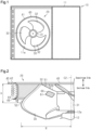
- the outdoor unit 10 includes a fan unit 20 and a case 11.
- the case 11 has the form of a laterally elongated box.
- the fan unit 20 is accommodated in the case 11.
- the fan unit 20 includes an axial fan 30 and a bell mouth 40.
- the bell mouth 40 is arranged on an outlet 11a of the case 11.
- the bell mouth 40 is disposed around the axial fan 30 so as to surround the axial fan 30.
- the axial fan 30 is connected to a rotation shaft 12a of an axial fan motor 12.
- the axial fan motor 12 is arranged in the case 11.
- the fan unit 20 is configured to draw in air through an inlet (not shown) of the case 11 and blow out the air from the outlet 11a of the case 11.
- the fan unit 20 is used as, for example, an air blowing device.
- the bell mouth 40 is accommodated in the case 11 in a state attached to the circumference of the outlet 11a of the case 11.
- the bell mouth 40 has a circumferential wall 41 that is ring-shaped as viewed from the front.
- the circumferential wall 41 includes a blow-out portion 42, a cylindrical portion 43, and a suction portion 44.
- an upstream side refers to the upstream side of the airflow generated by the axial fan 30, and a downstream side refers to the downstream side of the airflow generated by the axial fan 30.
- the blow-out portion 42 is located at a downstream end 45 of the bell mouth 40.
- the blow-out portion 42 is curved such that an inner diameter of the blow-out portion 42 decreases toward an upstream end 46 of the bell mouth 40.
- the cylindrical portion 43 continuously extends from an upstream end of the blow-out portion 42 toward the upstream end 46 of the bell mouth 40.
- the cylindrical portion 43 has an inner diameter that is constant from the upstream end of the blow-out portion 42 to a downstream end of the suction portion 44.
- the cylindrical portion 43 has an axis that coincides with an axis C1 of the bell mouth 40.
- the suction portion 44 continuously extends from an upstream end of the cylindrical portion 43.
- the suction portion 44 is curved such that an inner diameter of the suction portion 44 increases from the upstream end of the cylindrical portion 43 toward the upstream end 46 of the bell mouth 40.
- the thickness of the circumferential wall 41 is, for example, greater than or equal to 1 mm. Preferably, the thickness of the circumferential wall 41 is greater than or equal to 2 mm. The thickness of the circumferential wall 41 is, for example, less than or equal to 10 mm. Preferably, the thickness of the circumferential wall 41 is less than or equal to 5 mm. Preferably, the thickness of the circumferential wall 41 is in a range of 2 mm to 5 mm, inclusive.
- the material of the circumferential wall 41 is, for example, resin, ceramic, metal, or the like.
- the material of the circumferential wall 41 is resin so that the resin reduces the weight of the bell mouth 40 while maintaining the strength of the bell mouth 40.
- the bell mouth 40 includes a pressure-fluctuating-element passing part 60.
- the pressure-fluctuating-element passing part 60 is dotted. The details of the pressure-fluctuating-element passing part 60 will be described later.
- the axial fan 30 includes a hub 31 and a blade 32.
- the hub 31 is cylindrical.
- the material of the hub 31 is, for example, resin.
- the hub 31 includes an insertion hole 31a and an outer circumferential surface 31b.
- the hub 31 has an axis that coincides with an axis C2 of the axial fan 30.
- the insertion hole 31a is located in the center of the hub 31.
- the insertion hole 31a receives the rotation shaft 12a of the axial fan motor 12.
- Driving force of the axial fan motor 12 rotates the axial fan 30 in one direction.
- the axial fan 30 rotates in a rotation direction X as the rotation shaft 12a rotates.
- the rotation direction X is the rotation direction of the rotation shaft 12a.
- the number of blades 32 is five or less.
- the number of blades 32 is, for example, three.
- the number of blades 32 may be five, four, or two.
- the blades 32 are arranged on the outer circumferential surface 31b of the hub 31.
- the blades 32 each extend from the outer circumferential surface 31b in a radial direction of the hub 31.
- the radial direction of the hub 31 corresponds to a direction orthogonal to the rotation shaft 12a of the axial fan motor 12.
- a radial direction of the axial fan 30 coincides with the radial direction of the hub 31.
- the blades 32 are spaced apart from one another in the rotation direction X.
- the three blades 32 have the same shape.
- each of the blades 32 includes a positive pressure surface 32a and a negative pressure surface 32b.
- the positive pressure surface 32a is a blade surface located at a positive pressure side of the airflow generated by the rotation of the axial fan 30.
- the negative pressure surface 32b is a blade surface located at a negative pressure side of the airflow generated by the rotation of the axial fan 30.
- the blade 32 includes a porous part 61, the pores in the porous part 61 extend between the positive pressure surface 32a and the negative pressure surface 32b. Air flows out of the porous part 61 at the side of the positive pressure surface 32a as the axial fan 30 rotates. Air flows into the porous part 61 at the side of the negative pressure surface 32b as the axial fan 30 rotates.
- the blade 32 has a body 33.
- the material of the body 33 is, for example, resin.
- the hub 31 is formed integrally with the body 33.
- the hub 31 is formed integrally with the body 33, for example, by injection molding.
- the blade 32 includes the porous part 61.
- the porous part 61 is included in the pressure-fluctuating-element passing part 60. In Figs. 2 and 4 to 6 , the porous part 61 is dotted.
- the porous part 61 is located in a turbulent-flow interference portion 50 of the axial fan 30. The details of the turbulent-flow interference portion 50 and the porous part 61 will be described later.
- the body 33 includes a leading edge 33a, a trailing edge 33b, an inner peripheral edge 33c, and an outer peripheral edge 33d.
- the leading edge 33a is an edge located forward with respect to the rotation direction X.
- the trailing edge 33b is an edge located rearward with respect to the rotation direction X.
- the leading edge 33a is curved.
- the leading edge 33a is curved in an arcuate manner so as to be recessed toward the trailing edge 33b.
- the trailing edge 33b is curved.
- the trailing edge 33b is curved in an arcuate manner toward the trailing side with respect to the rotation direction X.
- the inner peripheral edge 33c is joined to the hub 31.
- the inner peripheral edge 33c extends between the leading edge 33a and the trailing edge 33b.
- the outer peripheral edge 33d extends between the leading edge 33a and the trailing edge 33b. In the radial direction of the axial fan 30, a dimension of the hub 31 from the rotation shaft 12a to the inner peripheral edge 33c is smaller than a dimension of the hub 31 from the rotation shaft 12a to the outer peripheral edge 33d.
- the outer peripheral edge 33d is curved.
- the outer peripheral edge 33d is curved in an arcuate manner so as to project in the radial direction of the axial fan 30.
- the first dimension L1 is a length of an imaginary line formed by connecting points located at the same distance from the axis C2 of the axial fan 30 in the radial direction of the axial fan 30 between the leading edge 33a and the trailing edge 33b. More specifically, when an arbitrary circle is drawn around the axis C2 of the axial fan 30, the first dimension L1 is a length of the arc extending between the leading edge 33a and the trailing edge 33b on a single blade 32. The first dimension L1 varies depending on the distance from the axis C2 of the axial fan 30 in the radial direction of the axial fan 30.
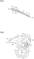
- a leading edge section 34 and a trailing edge section 35 of the blade 32 will now be described with reference to Fig. 5 .
- the blade 32 is divided into the leading edge section 34 and the trailing edge section 35 by an imaginary line formed by connecting the center points of multiple first dimensions L1.
- a section of the blade 32 between a center position P1 of the first dimensions L1 and the leading edge 33a is the leading edge section 34
- a section of the blade 32 between the center position P1 of the first dimensions L1 and the trailing edge 33b is the trailing edge section 35.
- the leading edge section 34 is heavier than the trailing edge section 35.
- the leading edge section 34 is heavier than the trailing edge section 35 because the body 33 gradually becomes thicker from the trailing edge 33b toward the leading edge 33a.
- the leading edge section 34 may be heavier than the trailing edge section 35 because the leading edge section 34 is partially thicker than the trailing edge section 35.
- the axial fan 30 and the bell mouth 40 each include the turbulent-flow interference portion 50.
- the turbulent-flow interference portion 50 includes, for example, part of the axial fan 30 or part of the bell mouth 40 that is likely to interfere with turbulent flow when pressure fluctuations occur in the air flowing between the bell mouth 40 and the axial fan 30.
- the turbulent-flow interference portion 50 is located on the axial fan 30 or the bell mouth 40.
- the turbulent-flow interference portion 50 may be located on the axial fan 30 and/or in the bell mouth 40.
- the turbulent-flow interference portion 50 may be located on both the axial fan 30 and the bell mouth 40.
- the turbulent-flow interference portion 50 includes an overlapping part 51 and an extension part 52.
- the overlapping part 51 is where the blade 32 overlaps the bell mouth 40 in the radial direction of the axial fan 30.
- the overlapping part 51 of the bell mouth 40 is defined where the imaginary cylindrical body overlaps the bell mouth 40 in the radial direction of the axial fan 30.
- the overlapping part 51 of the bell mouth 40 is defined where the imaginary cylindrical body overlaps the bell mouth 40 in the radial direction of the axial fan 30.
- the overlapping part 51 of the blade 32 is defined where the bell mouth 40 overlaps the blade 32 when the bell mouth 40 is projected onto the blade 32 in the radial direction of the axial fan 30.
- the overlapping part 51 is located on the bell mouth 40 and the axial fan 30.
- the overlapping part 51 varies depending on the positional relationship of the axial fan 30 and the bell mouth 40.
- a portion of the bell mouth 40 that corresponds to the overlapping part 51 includes the cylindrical portion 43, part of the blow-out portion 42, and part of the suction portion 44 of the bell mouth 40.
- a portion of the axial fan 30 that corresponds to the overlapping part 51 includes part of the trailing edge section 35 of the blade 32.
- the extension part 52 is located at the upstream side and the downstream side of the overlapping part 51. In other words, the extension part 52 is located at two opposite sides of the overlapping part 51 in the axial direction of the axial fan 30. The extension part 52 may be located on only one side of the overlapping part 51 in the axial direction of the axial fan 30.
- the extension part 52 varies depending on the positional relationship of the axial fan 30 and the bell mouth 40.
- the blow-out portion 42 and the suction portion 44 are curved so as to expand in a radial direction of the bell mouth 40.
- turbulent flow will not interfere with the blow-out portion 42 or the suction portion 44.
- the bell mouth 40 does not have a portion corresponding to the extension part 52.
- the extension part 52 of the axial fan 30 includes part of the trailing edge section 35 of the blade 32.
- the extension part 52 of the axial fan 30 may include part of the leading edge section 34 of the blade 32.
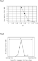
- Fig. 7 shows the level of noise reduction effect with respect to a ratio of the length h of the extension part 52 to the radius R of the axial fan 30.
- the graph in Fig. 7 was obtained through experiments. As shown in Fig. 7 , the wind noise was minimized when the length h was set to less than or equal to 0.1 times the radius R. Therefore, it is preferred that the length h of the extension part 52 in the axial direction of the axial fan 30 be less than or equal to 0.1 times the radius R of the axial fan 30.
- the blade 32 or the bell mouth 40 each include the pressure-fluctuating-element passing part 60 within the range of the turbulent-flow interference portion 50.
- the axial fan 30 or the bell mouth 40 each include the pressure-fluctuating-element passing part 60 within a range of a portion corresponding to the turbulent-flow interference portion 50. It is preferred that the pressure-fluctuating-element passing part 60 is entirely arranged within the range of respective turbulent-flow interference portion 50.
- the pressure-fluctuating-element passing part 60 and the porous part 61 will now be described with reference to Figs. 2 to 6 and 8 .
- the pressure-fluctuating-element passing part 60 is configured to reduce pressure fluctuations that occur between the axial fan 30 and the bell mouth 40.
- the pressure-fluctuating-element passing part 60 is arranged in the blade 32 of the axial fan 30 or the circumferential wall 41 of the bell mouth 40. In the present embodiment, the pressure-fluctuating-element passing part 60 is arranged in both the blade 32 and the circumferential wall 41.
- the pressure-fluctuating-element passing part 60 is arranged intermittently in the circumferential direction of the bell mouth 40.
- a plurality of pressure-fluctuating-element passing parts 60 are arranged at intervals in the circumferential direction of the bell mouth 40.
- the plurality of pressure-fluctuating-element passing parts 60 are arranged at equal intervals in the circumferential direction of the bell mouth 40.
- the number of pressure-fluctuating-element passing parts 60 arranged in a portion of the circumferential wall 41 corresponding to the turbulent-flow interference portion 50 is equal to, for example, the number of blades 32.
- three pressure-fluctuating-element passing parts 60 are arranged in the circumferential wall 41 of the bell mouth 40 in the circumferential direction.
- each of the pressure-fluctuating-element passing parts 60 extends over the cylindrical portion 43, part of the blow-out portion 42, and part of the suction portion 44 of the circumferential wall 41.
- the surface of the pressure-fluctuating-element passing part 60 is flush with the surface of the blow-out portion 42, the surface of the cylindrical portion 43, and the surface of the suction portion 44 of the circumferential wall 41.
- the pressure-fluctuating-element passing part 60 has substantially the same thickness as the portions of the circumferential wall 41 other than the pressure-fluctuating-element passing part 60.
- the pressure-fluctuating-element passing part 60 is formed by a porous body.
- the porous body extends through the circumferential wall 41 in a thickness-wise direction.
- the porous body has pores that are continuous with the outside of the porous body.
- the pores are holes that extend through the circumferential wall 41 in the thickness-wise direction.
- the average pore diameter of the pores is preferably 1000 ⁇ m or less, and more preferably 700 ⁇ m or less.
- the average pore diameter may be measured by any method.
- the average pore diameter may be measured, for example, by a gas adsorption method, which is also referred to as a Brunauer-Emmett-Teller (BET) method.
- BET Brunauer-Emmett-Teller
- the material of the pressure-fluctuating-element passing part 60 is, for example, resin, ceramic, metal, or the like.
- the resin is, for example, foamed plastic.
- the ceramic or metal is, for example, a porous sintered body.
- the metal may be a net-shaped body, which is also referred to as a mesh.
- the material of the porous body is a porous sintered body so that the average pore diameter can be easily controlled.
- the pressure-fluctuating-element passing part 60 may be arranged in the circumferential wall 41 of the bell mouth 40 by any method.
- an opening may be formed in the circumferential wall 41 of the bell mouth 40 for fitting the pressure-fluctuating-element passing part 60, and the pressure-fluctuating-element passing part 60 having a predetermined shape may be fitted to the opening.
- the pressure-fluctuating-element passing part 60 may be attached to a portion of the bell mouth 40 corresponding to the opening in the circumferential wall 41 using a known adhesive.
- the pressure-fluctuating-element passing part 60 may be formed in the bell mouth 40 by insert molding.
- the pressure-fluctuating-element passing part 60 includes the porous part 61.
- the material of the porous part 61 is, for example, resin, ceramic, metal, or the like.
- the resin is, for example, foamed plastic.
- the ceramic or metal is, for example, a porous sintered body.
- the metal may be a net-shaped body, which is also referred to as a mesh.
- the material of the porous part 61 is a porous sintered body so that the average pore diameter can be easily controlled.
- the porous part 61 has a lower strength than the body 33.
- the porous part 61 is located in a region surrounded by the leading edge 33a, the trailing edge 33b, the inner peripheral edge 33c, and the outer peripheral edge 33d.
- the porous part 61 is entirely surrounded by the body 33 having a higher strength than the porous part 61.
- the porous part 61 includes pores extending between the positive pressure surface 32a and the negative pressure surface 32b and are continuous with the outside of the porous part 61.
- the average pore diameter of the pores is preferably 1000 ⁇ m or less, and more preferably 700 ⁇ m or less.
- the porous part 61 has a thickness of 5 mm or less.
- the porous part 61 is integrated with the body 33.
- the porous part 61 is integrated with the body 33 by, for example, insert molding, adhesion, or fitting.
- the porous part 61 is quadrangular.
- the porous part 61 includes, for example, four curved corners.
- a length of an imaginary line formed by connecting points located at the same distance from the axis C2 of the axial fan 30 in the radial direction of the axial fan 30 between the leading edge 33a and the porous part 61 will be referred to as an arrangement distance L2.
- the arrangement distance L2 is a length of the arc extending between the leading edge 33a and a first end 61a of the porous part 61 that is located toward the leading edge 33a on a single blade 32.
- Expression (1) is satisfied at points where the distance from the rotation shaft 12a in the radial direction are the same.
- Expression (1) indicates that the porous part 61 is located at a position rearward from the leading edge 33a by 40% or more of the first dimension L1.
- Fig. 6 shows a border L11 that lies along positions located rearward from the leading edge 33a by 40% of the first dimensions L1.
- a first region 36 is defined between the leading edge 33a and the border L11.
- a second region 37 is defined between the border L11 and the trailing edge 33b.
- the second region 37 includes the border L11.
- the porous part 61 is located only in the second region 37.
- the porous part 61 is not located in the first region 36.
- the first dimension L1 and the arrangement distance L2 both vary depending on the distance from the rotation shaft 12a in the radial direction.
- the porous part 61 of the present embodiment is located within the range of the turbulent-flow interference portion 50 and where Expression (1) is satisfied.
- the radius R corresponds to a distance from the axis C2 of the axial fan 30 to the outer peripheral edge 33d or an imaginary extension line of the outer peripheral edge 33d.
- a distance from the inner peripheral edge 33c to a second end 61b of the porous part 61 that is located toward the outer peripheral edge 33d will be referred to as a first blade length R1.
- the relationship of the radius R and the first blade length R1 satisfies Expression (2).
- Expression (2) indicates that the porous part 61 is arranged in a portion of the blade 32 located within 70% of the radius R of the axial fan 30 from the rotation shaft 12a in the radial direction of the axial fan 30.
- the porous part 61 is arranged in the blade 32 to reduce the noise caused by the rotation of the axial fan 30.
- the noise reduction effect obtained by the porous part 61 is affected by the position of the porous part 61 in the range of the turbulent-flow interference portion 50.
- a dimension of the turbulent-flow interference portion 50 from the upstream end to the downstream end will be referred as an axial length H.
- the axial length H is a dimension obtained by adding the length of the overlapping part 51 in the axial direction and the length h of the extension part 52.
- the noise reduction effect was observed when the porous part 61 was located near the middle point of the turbulent-flow interference portion 50 of the blade 32 with respect to the axial length H.
- one of the imaginary lines defining the first dimensions L1 that extends through the middle point of the blade 32 will be referred to as a middle first dimension L3.
- a distance from the inner peripheral edge 33c to the middle first dimension L3 in the radial direction of the axial fan 30 will be referred to as a second blade length R2.
- a distance from the middle first dimension L3 to the outer peripheral edge 33d in the radial direction of the axial fan 30 will be referred to as a third blade length R3.
- the blade 32 When the blade 32 is divided into the inner peripheral region 38 and the outer peripheral region 39, a portion of the blade 32 corresponding to the third blade length R3 is the outer peripheral region 39.
- the inner peripheral region 38 is closer to the hub 31 than the outer peripheral region 39 is to the hub 31.
- the outer peripheral region 39 is closer to the outer peripheral edge 33d than the inner peripheral region 38 is to the outer peripheral edge 33d.
- Table 1 indicates a difference in the noise reduction effect when the pressure-fluctuating-element passing part 60 is arranged in both the turbulent-flow interference portion 50 of the bell mouth 40 and the turbulent-flow interference portion 50 of the blade 32, and the porous part 61 is located on different positions of the turbulent-flow interference portion 50 of the blade 32.
- the "Noise Reduction Effect” of Table 1 indicates values representing the reduced noise.
- the "Combined Use” of Table 1 refers to a case in which the pressure-fluctuating-element passing part 60 was arranged in both the bell mouth 40 and the blade 32. In a first example of Table 1, the position of the porous part 61 on the turbulent-flow interference portion 50 of the blade 32 was in the outer peripheral region 39 of the blade 32. In a second example of Table 1, the position of the porous part 61 on the turbulent-flow interference portion 50 of the blade 32 was in the trailing edge section 35 of the blade 32.
- the value representing the noise reduction effect was less than a value obtained by adding the values of the noise reduction effect when the pressure-fluctuating-element passing part 60 was arranged in only one of the turbulent-flow interference portion 50 of the bell mouth 40 and the turbulent-flow interference portion 50 of the blade 32 located in the outer peripheral region 39.
- the value representing the noise reduction effect was greater than a value obtained by adding the values of the noise reduction effect when the pressure-fluctuating-element passing part 60 was arranged in only one of the turbulent-flow interference portion 50 of the bell mouth 40 and the turbulent-flow interference portion 50 of the blade 32 located in the trailing edge section 35.
- Table 1 1st Example Pressure-Fluctuating-Element Passing Part Arrangement Position Outer Peripheral Region Bell Mouth Combined Use Noise Reduction Effect (dBA) 2.0 2.0 3.5 2nd Example Pressure-Fluctuating-Element Passing Part Arrangement Position Trailing Edge Section Bell Mouth Combined Use Noise Reduction Effect (dBA) 1.5 2.0 4.0
- the area of the porous part 61 is less than the area of the blade 32.
- the entire area of the positive pressure surface 32a is greater than the area of the porous part 61.
- the area of the porous part 61 is less than or equal to 30% of the area of the blade 32.
- the area of the porous part 61 is, for example, less than or equal to 30% of the entire area of the positive pressure surface 32a.
- both the axial fan 30 and the bell mouth 40 include the pressure-fluctuating-element passing part 60
- the noise reduction effect is affected by the position of the porous part 61 on the axial fan 30.
- the pressure-fluctuating-element passing part 60 is arranged in both the turbulent-flow interference portion 50 of the bell mouth 40 and the turbulent-flow interference portion 50 of the blade 32 located in the trailing edge section 35
- the noise reduction effect becomes greater than the value obtained by combining the noise reduction effects when the pressure-fluctuating-element passing part 60 is arranged in either of the turbulent-flow interference portion 50 of the bell mouth 40 or the turbulent-flow interference portion 50 of the blade 32 located in the trailing edge section 35.
- the first embodiment has the following advantages.
- the fan unit 20 includes the axial fan 30 and the bell mouth 40.
- the axial fan 30 includes the hub 31 and the blade 32.
- the hub 31 is attached to the rotation shaft 12a.
- the blade 32 is arranged on the hub 31.
- the axial fan 30 and the bell mouth 40 each include the turbulent-flow interference portion 50.
- the turbulent-flow interference portion 50 includes the overlapping part 51 and the extension part 52. In the overlapping part 51, the blade 32 overlaps the bell mouth 40 in the radial direction of the axial fan 30.
- the extension part 52 is located at two opposite sides of the overlapping part 51 in the axial direction of the axial fan 30.
- the length h of the extension part 52 in the axial direction is less than or equal to 0.1 times of the radius R of the axial fan 30.
- the blade 32 or the bell mouth 40 includes the pressure-fluctuating-element passing part 60 within the range of the turbulent-flow interference portion 50.
- the pressure-fluctuating-element passing part 60 is configured to reduce pressure fluctuations that occur between the axial fan 30 and the bell mouth 40.
- the pressure-fluctuating-element passing part 60 is arranged in the turbulent-flow interference portion 50 of the axial fan 30 or the turbulent-flow interference portion 50 of the bell mouth 40.
- turbulent flow readily passes through the pressure-fluctuating-element passing part 60. This minimizes the wind noise caused by surface vortex.
- surface vortex is a vortex that occurs on the surface of the blade 32 or the surface of the circumferential wall 41 of the bell mouth 40.
- the blade 32 includes the leading edge 33a and the trailing edge 33b.
- the leading edge 33a is located forward with respect to the rotation direction X of the rotation shaft 12a.
- the trailing edge 33b is located rearward with respect to the rotation direction X of the rotation shaft 12a.
- the pressure-fluctuating-element passing part 60 includes the porous part 61.
- the porous part 61 is located at a position rearward from the leading edge 33a by 40% or more of the first dimension L1.
- the porous part 61 is located rearward from the leading edge 33a by 40% or more of the first dimension L1. This reduces the noise generated near the trailing edge 33b of the blade 32.
- the fan unit 20 includes the axial fan 30 and the bell mouth 40.
- the axial fan 30 includes the hub 31 and the blade 32.
- the hub 31 is attached to the rotation shaft 12a.
- the blade 32 is arranged on the hub 31.
- the axial fan 30 and the bell mouth 40 each include the turbulent-flow interference portion 50.
- the turbulent-flow interference portion 50 includes the overlapping part 51 and the extension part 52. In the overlapping part 51, the blade 32 overlaps the bell mouth 40 in the radial direction of the axial fan 30.
- the extension part 52 is located at two opposite sides of the overlapping part 51 in the axial direction of the axial fan 30.
- the length h of the extension part 52 in the axial direction is less than or equal to 0.1 times of the radius R of the axial fan 30.
- the blade 32 and the bell mouth 40 each include the pressure-fluctuating-element passing part 60 within the range of respective turbulent-flow interference portion 50.
- the pressure-fluctuating-element passing part 60 is configured to reduce pressure fluctuations that occur between the axial fan 30 and the bell mouth 40.
- the blade 32 includes the leading edge 33a and the trailing edge 33b.
- the leading edge 33a is located forward with respect to the rotation direction X of the rotation shaft 12a.
- the trailing edge 33b is located rearward with respect to the rotation direction X of the rotation shaft 12a.
- the pressure-fluctuating-element passing part 60 arranged in the blade 32 includes the porous part 61.
- the porous part 61 is located at a position rearward from the leading edge 33a by 40% or more of the first dimension L1.
- the pressure-fluctuating-element passing part 60 is arranged in both the turbulent-flow interference portion 50 of the axial fan 30 and the turbulent-flow interference portion 50 of the bell mouth 40.
- turbulent flow readily passes through the pressure-fluctuating-element passing part 60. This minimizes the wind noise caused by surface vortex.
- the porous part 61 is arranged in a portion of the blade 32 located within 70% of the radius R of the axial fan 30 from the rotation shaft 12a in the radial direction of the axial fan 30.
- the porous part 61 is located rearward from the leading edge 33a of the blade 32 by 40% or more of the first dimension L1 and within 70% of the radius R of the axial fan 30 from the rotation shaft 12a. This reduces the noise generated near the trailing edge 33b of the blade 32.
- the area of the porous part 61 is less than or equal to 30% of the area of the blade 32.
- This structure maintains the strength of the blade 32 as compared to a structure in which the porous part 61 is arranged in a wider range of the blade 32.
- the pressure-fluctuating-element passing part 60 includes the pores extending through the blade 32 or the bell mouth 40 in respective thickness-wise direction.
- the pores have an average pore diameter of 1000 ⁇ m or less.
- this structure avoids a situation in which an excessive amount of air passes through the pressure-fluctuating-element passing part 60 while allowing passage of the air in the vicinity of the circumferential wall 41 through the pressure-fluctuating-element passing part 60. This reduces loss of the air flowing through the axial fan 30.
- the pressure-fluctuating-element passing part 60 is arranged intermittently in the circumferential direction of the bell mouth 40.
- This structure maintains the strength of the bell mouth 40 as compared to a structure in which the pressure-fluctuating-element passing part 60 is continuously arranged in the circumferential direction of the bell mouth 40.
- the outdoor unit 10 includes the fan unit 20.
- a second embodiment of the fan unit 20 will now be described with reference to Figs. 9 and 10 .
- the differences from the first embodiment will be described.
- the same reference names are given to those elements that are the same as the corresponding elements of the first embodiment, and such elements will not be described in detail.
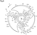
- a trailing edge 71 of an axial fan 70 in accordance with the second embodiment includes an inner peripheral connecting part 72, an outer peripheral connecting part 73, and a notch defining part 74.
- the inner peripheral connecting part 72 is connected to the inner peripheral edge 33c.
- the inner peripheral connecting part 72 extends from the inner peripheral edge 33c toward the notch defining part 74.
- the inner peripheral connecting part 72 is inclined toward the trailing side with respect to the rotation direction X of the axial fan 70 as the inner peripheral connecting part 72 approaches the notch defining part 74 from the inner peripheral edge 33c.
- the outer peripheral connecting part 73 is connected to the outer peripheral edge 33d.
- the outer peripheral connecting part 73 extends from the notch defining part 74 toward the outer peripheral edge 33d.
- the outer peripheral connecting part 73 is inclined toward the trailing side with respect to the rotation direction X of the axial fan 70 as the outer peripheral connecting part 73 approaches the notch defining part 74 from the outer peripheral edge 33d.
- the notch defining part 74 is located between the inner peripheral connecting part 72 and the outer peripheral connecting part 73.
- the notch defining part 74 connects the inner peripheral connecting part 72 and the outer peripheral connecting part 73.
- the notch defining part 74 includes a first section 75, a second section 76, and a third section 77.
- the first section 75 is connected to the inner peripheral connecting part 72.
- the first section 75 extends from the inner peripheral connecting part 72 toward the leading edge 33a.
- the first section 75 is inclined toward the leading side with respect to the rotation direction X of the axial fan 70 as the first section 75 approaches the outer peripheral edge 33d from the inner peripheral connecting part 72.
- the second section 76 is connected to the outer peripheral connecting part 73.
- the second section 76 extends from the outer peripheral connecting part 73 toward the leading edge 33a.
- the second section 76 is inclined toward the leading side with respect to the rotation direction X of the axial fan 70 as the second section 76 extends away from the outer peripheral connecting part 73.
- the distance between the first section 75 and the second section 76 decreases toward the leading edge 33a.
- the third section 77 connects the first section 75 and the second section 76.
- the third section 77 is curved so as to be recessed toward the leading edge 33a.
- a region defined by the first section 75, the second section 76, and the third section 77 is the notch 78.
- the notch defining part 74 defines the notch 78.
- the notch 78 is arranged to improve airflow and reduce noise.
- the notch 78 extends between the positive pressure surface 32a and the negative pressure surface 32b.
- the notch 78 is recessed toward the leading edge 33a.
- an imaginary line that extends in the rotation direction X through a center position P2 of the third section 77 will be referred to as a trajectory L12.
- the center position P2 of the third section 77 is a point of the notch defining part 74 that is closest to the leading edge 33a.
- a portion of the blade 32 located closer to the inner peripheral edge 33c than the trajectory L12 is to the inner peripheral edge 33c will be referred to as an inner peripheral region 79.
- a portion of the blade 32 located closer to the outer peripheral edge 33d than the trajectory L12 is to the outer peripheral edge 33d will be referred to as an outer peripheral region 80.
- the inner peripheral region 79 includes the trajectory L12.
- the porous part 61 is arranged in a portion of the blade 32 located closer to the rotation shaft 12a than the notch 78 is to the rotation shaft 12a in the radial direction of the axial fan 30.
- the porous part 61 is arranged, for example, in a portion of the blade 32 located closer to the inner peripheral edge 33c than the trajectory L12 is to the inner peripheral edge 33c.
- the porous part 61 is arranged between the first section 75 and the inner peripheral edge 33c of the blade 32 in the radial direction of the axial fan 30.
- Table 2 indicates a difference in the noise reduction effect of the fan unit 20 including the axial fan 70 of the second embodiment when the pressure-fluctuating-element passing part 60 is arranged in both the turbulent-flow interference portion 50 of the bell mouth 40 and the turbulent-flow interference portion 50 of the blade 32, and the porous part 61 is located on different positions of the turbulent-flow interference portion 50 of the blade 32.
- the "Noise Reduction Effect” of Table 2 indicates values representing the reduced noise.
- the "Combined Use" of Table 2 refers to a case in which the pressure-fluctuating-element passing part 60 was arranged in both the bell mouth 40 and the blade 32.
- the position of the porous part 61 on the turbulent-flow interference portion 50 of the blade 32 was in the outer peripheral region 80 of the blade 32.
- the position of the porous part 61 on the turbulent-flow interference portion 50 of the blade 32 was in the inner peripheral region 79 of the blade 32 located in the trailing edge section 35.
- the value representing the noise reduction effect was 1.8 dBA.
- the value representing the noise reduction effect was 0.5 dBA.
- the value representing the noise reduction effect was 2.1 dBA.
- the value representing the noise reduction effect was less than a value obtained by adding the values of the noise reduction effect when the pressure-fluctuating-element passing part 60 was arranged in only one of the turbulent-flow interference portion 50 of the bell mouth 40 and the turbulent-flow interference portion 50 of the blade 32 located in the outer peripheral region 80.
- the value representing the noise reduction effect was greater than a value obtained by adding the values of the noise reduction effect when the pressure-fluctuating-element passing part 60 was arranged in only one of the turbulent-flow interference portion 50 of the bell mouth 40 and the turbulent-flow interference portion 50 of the blade 32 located in the trailing edge section 35 and within the inner peripheral region 79.
- the second embodiment has the following advantages in addition to the advantages of the first embodiment.
- the porous part 61 is arranged in a portion located closer to the rotation shaft 12a than the notch 78 is to the rotation shaft 12a in the radial direction. This reduces the noise generated near the trailing edge 71 of the blade 32.
- a third embodiment of the fan unit 20 will now be described with reference to Figs. 11 to 14 .
- differences from the first and second embodiments will be described.
- the same reference names are given to those elements that are the same as the corresponding elements of the first and second embodiments, and such elements will not be described in detail.
- the blade 32 includes the porous part 61, and the bell mouth 40 does not include the porous part 61.
- the porous part 61 is arranged in, for example, the body 33 of the blade 32.
- the porous part 61 arranged in the blade 32 is dotted.
- the porous part 61 is substantially elliptical.
- the porous part 61 does not have to be elliptical, and may be circular or quadrangular.
- a ratio of the length of the major axis to the length of the minor axis is in a range of 1.3 to 1.8, inclusive.
- the porous part 61 is arranged such that the center of the porous part 61 is located within a region that is defined by a circle having a predetermined radius and centered on the center of gravity of the blade 32.
- the predetermined radius is smaller than the radius R of the axial fan 30.
- the porous part 61 is arranged such that the center of the porous part 61 coincides with the center of gravity of the blade 32.
- the extension part 52 of the turbulent-flow interference portion 50 located at the upstream side of the overlapping part 51 will be defined as a first extension part 53.
- the first extension part 53 extends from the upstream end 46 of the bell mouth 40 toward the upstream side of the airflow generated by the axial fan 30.
- a length h1 of the first extension part 53 is 0.1 times the radius R of the axial fan 30.
- a region defined by the first extension part 53 will be referred to as a first extension region.
- the porous part 61 is arranged in the blade 32 such that the porous part 61 is partially located in the first extension region.
- the porous part 61 is arranged in the blade 32 such that a third end 61c of the porous part 61 that is closest to the upstream end 46 of the bell mouth 40 is located in the first extension region.
- a length t from the upstream end 46 of the bell mouth 40 to the third end 61c is less than or equal to the length h1 of the first extension part 53.
- the ratio A1 is a ratio of the length t from the upstream end 46 of the bell mouth 40 to the third end 61c relative to the length h1 of the first extension part 53.
- Fig. 13 shows the level of the noise reduction effect with respect to the ratio A1.
- the graph in Fig. 13 was obtained through experiments. As shown in Fig. 13 , the wind noise was reduced when the ratio A1 was set in a range of 0.4 to 0.9, inclusive. In particular, the wind noise was minimized when the ratio A1 was set in a range of 0.5 to 0.7, inclusive. Therefore, it is preferred that the ratio A1 be set in a range of 0.5 to 0.7, inclusive.
- the area of the porous part 61 is less than the area of the blade 32.
- the area of the porous part 61 is less than or equal to 30% of the area of the blade 32.
- the area of the porous part 61 is, for example, less than or equal to 30% of the entire area of the positive pressure surface 32a.
- a ratio A2 of the area of the porous part 61 to the area of the blade 32 is less than or equal to 0.3.
- the ratio of the area of the porous part 61 to the entire area of the positive pressure surface 32a is, for example, less than or equal to 0.3.
- the area of the porous part 61 is less than or equal to 25% of the area of the blade 32.
- the area of the porous part 61 is, for example, less than or equal to 25% of the entire area of the positive pressure surface 32a.
- the ratio A2 is less than or equal to 0.25.
- the ratio of the area of the porous part 61 to the entire area of the positive pressure surface 32a is, for example, less than or equal to 0.25.
- Fig. 14 shows the level of maximum stress on the blade 32 with respect to the ratio A2.
- the graph in Fig. 14 was obtained through experiments. As shown in Fig. 14 , the maximum stress on the blade 32 was maintained when the porous part 61 arranged in the blade 32 had the ratio A2 of 0.3 or less. In particular, the maximum stress on the blade 32 was maintained effectively when the porous part 61 arranged in the blade 32 had the ratio A2 of 0.25 or less. Therefore, it is preferred that the porous part 61 arranged in the blade 32 have the ratio A2 of 0.25 or less.
- the porous part 61 is located at a position rearward from the leading edge 33a by 40% or more of the first dimension L1.
- the porous part 61 is arranged in a portion of the blade 32 located within 70% of the radius R of the axial fan 30 from the rotation shaft 12a in the radial direction.
- the trailing edge 33b of the blade 32 may include the notch 78.
- the porous part 61 is arranged in a portion of the blade 32 located closer to the rotation shaft 12a than the notch 78 is to the rotation shaft 12a in the radial direction.
- the fan unit 20 and the outdoor unit 10 according to the present disclosure are applicable to modified examples that are described below and combinations of at least two of the modified examples that do not contradict each other.
- the outdoor unit 10 may be an outdoor unit of a heat pump water heater that generates hot water by refrigeration cycle and stores the generated hot water.
- the pressure-fluctuating-element passing part 60 may be arranged in only the axial fan 30.
- the pressure-fluctuating-element passing part 60 may be arranged in only the bell mouth 40.
- the circumferential wall 41 of the bell mouth 40 does not have to include the cylindrical portion 43.
- the circumferential wall 41 of the bell mouth 40 may be formed by the blow-out portion 42 and the suction portion 44 that are continuous with each other.
- the pressure-fluctuating-element passing part 60 and the porous part 61 may each be a porous body having a large number of through holes extending in a single direction.
- the porous body having a large number of through holes extending in a single direction may be prepared, for example, by inserting a needle-shaped member through a solid resin body a number of times from one direction.
- the porous part 61 may be arranged in the bell mouth 40, in addition to the blade 32.
- the porous part 61 is arranged intermittently in the circumferential direction of the bell mouth 40 within the range of the turbulent-flow interference portion 50 of the bell mouth 40.
Landscapes
- Engineering & Computer Science (AREA)
- Mechanical Engineering (AREA)
- General Engineering & Computer Science (AREA)
- Chemical & Material Sciences (AREA)
- Combustion & Propulsion (AREA)
- Structures Of Non-Positive Displacement Pumps (AREA)
Abstract
Description
- The present disclosure relates to a fan unit and an outdoor unit.
-
Patent Literature 1 discloses an axial fan including porous sections. The axial fan ofPatent Literature 1 including the porous sections restricts pressure fluctuations and reduces noise. - Patent Literature 1:
Japanese Patent No. 2754862 - There is still room for improvement in the designs of an axial fan or a bell mouth in order to reduce wind noise.
- An objective of the present disclosure is to provide a fan unit that minimizes wind noise. Solution to Problem
- A fan unit in accordance with a first aspect that solves the above problem includes an axial fan and a bell mouth. The axial fan includes a hub attached to a rotation shaft, and a blade arranged on the hub. The axial fan includes a turbulent-flow interference portion. The turbulent-flow interference portion includes an overlapping part and an extension part. In the overlapping part, the blade overlaps the bell mouth in a radial direction of the axial fan. The extension part is located at two opposite sides of the overlapping part in an axial direction of the axial fan. A length of the extension part in the axial direction is less than or equal to 0.1 times a radius of the axial fan. The blade includes a porous part within a range of the turbulent-flow interference portion. An area of the porous part is less than or equal to 30% of an area of the blade.
- With this structure, the porous part is arranged in the turbulent-flow interference portion of the axial fan. Thus, when pressure fluctuations occur in the air flowing between the bell mouth and the axial fan, turbulent flow readily passes through the porous part. This minimizes the wind noise caused by surface vortex.
- In accordance with a second aspect, the fan unit according to the first aspect is configured so that the area of the porous part is less than or equal to 25% of the area of the blade.
- With this structure, the porous part is arranged in the turbulent-flow interference portion of the axial fan. Thus, when pressure fluctuations occur in the air flowing between the bell mouth and the axial fan, turbulent flow readily passes through the porous part in an optimal manner. This optimally minimizes the wind noise caused by surface vortex.
- In accordance with a third aspect, the fan unit according to the first or second aspect is configured so that the blade includes a leading edge and a trailing edge. The leading edge is located forward with respect to a rotation direction of the rotation shaft. The trailing edge is located rearward with respect to the rotation direction of the rotation shaft. When a dimension from the leading edge to the trailing edge is referred to as a first dimension, the porous part is located at a position rearward from the leading edge by 40% or more of the first dimension.
- With this structure, the porous part is located rearward from the leading edge by 40% or more of the first dimension. This reduces the noise generated near the trailing edge of the blade.
- In accordance with a fourth aspect, the fan unit according to any one of the first to third aspects is configured so that the porous part is arranged in a portion of the blade located within 70% of the radius of the axial fan from the rotation shaft in the radial direction.
- With this structure, the porous part is located within 70% of the radius of the axial fan from the rotation shaft. This reduces the noise generated near the trailing edge of the blade.
- In accordance with a fifth aspect, the fan unit according to any one of the first to fourth aspects is configured so that the blade includes a trailing edge located rearward with respect to a rotation direction of the rotation shaft. The trailing edge includes a notch. The porous part is arranged in a portion of the blade located closer to the rotation shaft than the notch is to the rotation shaft in the radial direction.
- With this structure, the porous part is arranged in a portion located closer to the rotation shaft than the notch is to the rotation shaft in the radial direction. This reduces the noise generated near the trailing edge of the blade.
- In accordance with a sixth aspect, the fan unit according to any one of the first to fifth aspects is configured so that the porous part includes pores extending through the blade in a thickness-wise direction, the pores having an average pore diameter of 1000 µm or less.
- When pressure fluctuations occur, this structure avoids a situation in which an excessive amount of air passes through the porous part while allowing passage of the air in the vicinity of the surface of the blade or in the vicinity of the surface of the circumferential wall of the bell mouth through the porous part. This reduces loss of the air flowing through the axial fan.
- In accordance with a seventh aspect, the fan unit according to any one of the first to sixth aspects is configured so that the bell mouth includes the overlapping part. The bell mouth includes the porous part within a range of the overlapping part. The porous part is arranged intermittently in a circumferential direction of the bell mouth.
- With this structure, the porous part is arranged intermittently in the turbulent-flow interference portion of the bell mouth. Thus, when pressure fluctuations occur in the air flowing between the bell mouth and the axial fan, turbulent flow readily passes through the porous part. This minimizes the wind noise caused by surface vortex.
- An outdoor unit in accordance with an eighth aspect that solves the above problem includes the fan unit according to any one of the first to seventh aspects.
- When pressure fluctuations occur in the air flowing between the bell mouth and the axial fan, this structure allows turbulent flow to readily pass through the porous part. Thus, the outdoor unit minimizes the wind noise caused by surface vortex.
- A fan unit in accordance with a ninth aspect that solves the above problem includes the axial fan and the bell mouth. The axial fan includes the hub and the blade. The hub is attached to the rotation shaft. The blade is arranged on the hub. The axial fan and the bell mouth each include the turbulent-flow interference portion. The turbulent-flow interference portion includes the overlapping part and the extension part. In the overlapping part, the blade overlaps the bell mouth in the radial direction of the axial fan. The extension part is located at two opposite sides of the overlapping part in the axial direction of the axial fan. The length h of the extension part in the axial direction is less than or equal to 0.1 times of the radius of the axial fan. The blade or the bell mouth includes the pressure-fluctuating-element passing part within the range of the turbulent-flow interference portion. The pressure-fluctuating-element passing part is configured to reduce pressure fluctuations that occur between the axial fan and the bell mouth.
- With this structure, the pressure-fluctuating-element passing part is arranged in the turbulent-flow interference portion of the axial fan or the turbulent-flow interference portion of the bell mouth. Thus, when pressure fluctuations occur in the air flowing between the bell mouth and the axial fan, turbulent flow readily passes through the pressure-fluctuating-element passing part. This minimizes the wind noise caused by surface vortex.
- In accordance with a tenth aspect, the fan unit according to the ninth aspect is configured so that the blade includes the leading edge and the trailing edge. The leading edge is located forward with respect to the rotation direction of the rotation shaft. The trailing edge is located rearward with respect to the rotation direction of the rotation shaft. When the blade includes the pressure-fluctuating-element passing part within the range of the turbulent-flow interference portion, the pressure-fluctuating-element passing part includes the porous part. When the dimension from the leading edge to the trailing edge is referred to as the first dimension, the porous part is located at a position rearward from the leading edge by 40% or more of the first dimension.
- With this structure, the porous part is located rearward from the leading edge by 40% or more of the first dimension. This reduces the noise generated near the trailing edge of the blade.
- A fan unit in accordance with an eleventh aspect that solves the above problem includes the axial fan and the bell mouth. The axial fan includes the hub and the blade. The hub is attached to the rotation shaft. The blade is arranged on the hub. The axial fan and the bell mouth each include the turbulent-flow interference portion. The turbulent-flow interference portion includes the overlapping part and the extension part. In the overlapping part, the blade overlaps the bell mouth in the radial direction of the axial fan. The extension part is located at two opposite sides of the overlapping part in the axial direction of the axial fan. The length h of the extension part in the axial direction is less than or equal to 0.1 times of the radius of the axial fan. The blade and the bell mouth each include the pressure-fluctuating-element passing part within the range of respective turbulent-flow interference portion. The pressure-fluctuating-element passing part is configured to reduce pressure fluctuations that occur between the axial fan and the bell mouth. The blade includes the leading edge and the trailing edge. The leading edge is located forward with respect to the rotation direction of the rotation shaft. The trailing edge is located rearward with respect to the rotation direction of the rotation shaft. The pressure-fluctuating-element passing part arranged in the blade includes the porous part. When the dimension from the leading edge to the trailing edge is referred to as the first dimension, the porous part is located at a position rearward from the leading edge by 40% or more of the first dimension.
- With this structure, the pressure-fluctuating-element passing part is arranged in both the turbulent-flow interference portion of the axial fan and the turbulent-flow interference portion of the bell mouth. Thus, when pressure fluctuations occur in the air flowing between the bell mouth and the axial fan, turbulent flow readily passes through the pressure-fluctuating-element passing part. This minimizes the wind noise caused by surface vortex.
- In accordance with a twelfth aspect, the fan unit according to the tenth or eleventh aspect is configured so that the porous part is arranged in a portion of the blade located within 70% of the radius of the axial fan from the rotation shaft in the radial direction.
- With this structure, the porous part is located rearward from the leading edge of the blade by 40% or more of the first dimension and within 70% of the radius of the axial fan from the rotation shaft. This reduces the noise generated near the trailing edge of the blade.
- In accordance with a thirteenth aspect, the fan unit according to any one of the tenth to twelfth aspects is configured so that when the trailing edge includes a notch, the porous part is arranged in a portion of the blade located closer to the rotation shaft than the notch is to the rotation shaft in the radial direction.
- With this structure, the porous part is arranged in a portion located closer to the rotation shaft than the notch is to the rotation shaft in the radial direction. This reduces the noise generated near the trailing edge of the blade.
- In accordance with a fourteenth aspect, the fan unit according to any one of the tenth to thirteenth aspects is configured so that the area of the porous part is less than or equal to 30% of the area of the blade.
- This structure maintains the strength of the blade as compared to a structure in which the porous part is arranged in a wider range of the blade.
- In accordance with a fifteenth aspect, the fan unit according to the ninth to fourteenth aspects is configured so that the pressure-fluctuating-element passing part includes the pores extending through the blade or the bell mouth in respective thickness-wise direction. The pores have an average pore diameter of 1000 µm or less.
- When pressure fluctuations occur, this structure avoids a situation in which an excessive amount of air passes through the pressure-fluctuating-element passing part while allowing passage of the air in the vicinity of the surface of the blade or in the vicinity of the surface of the circumferential wall of the bell mouth through the pressure-fluctuating-element passing part. This reduces loss of the air flowing through the axial fan.
- In accordance with a sixteenth aspect, the fan unit according to the ninth, tenth, and twelfth to fifteenth aspects is configured so that when the bell mouth includes the pressure-fluctuating-element passing part within the range of the turbulent-flow interference portion, the pressure-fluctuating-element passing part is arranged intermittently in the circumferential direction of the bell mouth.
- This structure maintains the strength of the bell mouth as compared to a structure in which the pressure-fluctuating-element passing part is continuously arranged in the circumferential direction of the bell mouth.
- An outdoor unit in accordance with a seventeenth aspect that solves the above problem includes the fan unit according to the ninth to sixteenth aspects.
- When pressure fluctuations occur in the air flowing between the bell mouth and the axial fan, this structure allows turbulent flow to readily pass through the pressure-fluctuating-element passing part. This minimizes the wind noise caused by surface vortex.
-
-
Fig. 1 is a schematic front view showing the inside of an outdoor unit including a fan unit. -
Fig. 2 is a schematic cross-sectional view showing part of the fan unit shown inFig. 1 . -
Fig. 3 is a perspective view of a bell mouth shown inFig. 2 . -
Fig. 4 is a front view of an axial fan shown inFig. 2 as viewed from the side of a positive pressure surface. -
Fig. 5 is a cross-sectional view of a blade taken along line D5-D5 shown inFig. 4 . -
Fig. 6 is an enlarged view of the axial fan shown inFig. 4 . -
Fig. 7 is a graph showing the level of noise reduction effect with respect to a ratio of a length of an extension part to a radius of the axial fan. -
Fig. 8 is a graph showing the level of the noise reduction effect with respect to a position of a porous part arranged in the blade. -
Fig. 9 is a front view of an axial fan in accordance with a second embodiment as viewed from the side of a positive pressure surface. -
Fig. 10 is an enlarged view of a blade in accordance with the second embodiment. -
Fig. 11 is a schematic cross-sectional view showing part of a fan unit in accordance with a third embodiment. -
Fig. 12 is a front view of an axial fan in accordance with the third embodiment as viewed from the side of a positive pressure surface. -
Fig. 13 is a graph showing the level of noise reduction effect by the axial fan in accordance with the third embodiment with respect to a ratio of a length from an upstream end of a bell mouth to a third end relative to a length of a first extension part. -
Fig. 14 is a graph showing the level of maximum stress on a blade with respect to a ratio of an area of a porous part to an area of the blade. - A first embodiment of a fan unit will now be described with reference to
Figs. 1 to 6 . - An
outdoor unit 10 will be described with reference toFigs. 1 and 2 . Theoutdoor unit 10 of the present embodiment is an outdoor unit for an air conditioner that cools and heats the living space inside a room. Theoutdoor unit 10 is connected to an indoor unit by a refrigerant pipe. Theoutdoor unit 10 includes afan unit 20 and acase 11. There is no limitation on the shape of thecase 11. For example, thecase 11 has the form of a laterally elongated box. Thefan unit 20 is accommodated in thecase 11. - The
fan unit 20 includes anaxial fan 30 and abell mouth 40. Thebell mouth 40 is arranged on anoutlet 11a of thecase 11. Thebell mouth 40 is disposed around theaxial fan 30 so as to surround theaxial fan 30. Theaxial fan 30 is connected to arotation shaft 12a of anaxial fan motor 12. Theaxial fan motor 12 is arranged in thecase 11. - The
fan unit 20 is configured to draw in air through an inlet (not shown) of thecase 11 and blow out the air from theoutlet 11a of thecase 11. Thefan unit 20 is used as, for example, an air blowing device. - As shown in
Figs. 1 to 3 , thebell mouth 40 is accommodated in thecase 11 in a state attached to the circumference of theoutlet 11a of thecase 11. Thebell mouth 40 has acircumferential wall 41 that is ring-shaped as viewed from the front. Thecircumferential wall 41 includes a blow-outportion 42, acylindrical portion 43, and asuction portion 44. In the following description of the present embodiment, an upstream side refers to the upstream side of the airflow generated by theaxial fan 30, and a downstream side refers to the downstream side of the airflow generated by theaxial fan 30. - The blow-out
portion 42 is located at adownstream end 45 of thebell mouth 40. The blow-outportion 42 is curved such that an inner diameter of the blow-outportion 42 decreases toward anupstream end 46 of thebell mouth 40. Thecylindrical portion 43 continuously extends from an upstream end of the blow-outportion 42 toward theupstream end 46 of thebell mouth 40. Thecylindrical portion 43 has an inner diameter that is constant from the upstream end of the blow-outportion 42 to a downstream end of thesuction portion 44. Thecylindrical portion 43 has an axis that coincides with an axis C1 of thebell mouth 40. - The
suction portion 44 continuously extends from an upstream end of thecylindrical portion 43. Thesuction portion 44 is curved such that an inner diameter of thesuction portion 44 increases from the upstream end of thecylindrical portion 43 toward theupstream end 46 of thebell mouth 40. - There is no limitation to the thickness of the
circumferential wall 41. The thickness of thecircumferential wall 41 is, for example, greater than or equal to 1 mm. Preferably, the thickness of thecircumferential wall 41 is greater than or equal to 2 mm. The thickness of thecircumferential wall 41 is, for example, less than or equal to 10 mm. Preferably, the thickness of thecircumferential wall 41 is less than or equal to 5 mm. Preferably, the thickness of thecircumferential wall 41 is in a range of 2 mm to 5 mm, inclusive. - There is no limitation to the material of the
circumferential wall 41. The material of thecircumferential wall 41 is, for example, resin, ceramic, metal, or the like. Preferably, the material of thecircumferential wall 41 is resin so that the resin reduces the weight of thebell mouth 40 while maintaining the strength of thebell mouth 40. - As shown in
Figs. 2 and3 , thebell mouth 40 includes a pressure-fluctuating-element passing part 60. InFigs. 2 and3 , the pressure-fluctuating-element passing part 60 is dotted. The details of the pressure-fluctuating-element passing part 60 will be described later. - As shown in
Figs. 2 and4 , theaxial fan 30 includes ahub 31 and ablade 32. Thehub 31 is cylindrical. The material of thehub 31 is, for example, resin. Thehub 31 includes aninsertion hole 31a and an outercircumferential surface 31b. Thehub 31 has an axis that coincides with an axis C2 of theaxial fan 30. Theinsertion hole 31a is located in the center of thehub 31. Theinsertion hole 31a receives therotation shaft 12a of theaxial fan motor 12. Driving force of theaxial fan motor 12 rotates theaxial fan 30 in one direction. Theaxial fan 30 rotates in a rotation direction X as therotation shaft 12a rotates. The rotation direction X is the rotation direction of therotation shaft 12a. - The number of
blades 32 is five or less. The number ofblades 32 is, for example, three. The number ofblades 32 may be five, four, or two. Theblades 32 are arranged on the outercircumferential surface 31b of thehub 31. Theblades 32 each extend from the outercircumferential surface 31b in a radial direction of thehub 31. The radial direction of thehub 31 corresponds to a direction orthogonal to therotation shaft 12a of theaxial fan motor 12. A radial direction of theaxial fan 30 coincides with the radial direction of thehub 31. Theblades 32 are spaced apart from one another in the rotation direction X. The threeblades 32 have the same shape. - As shown in
Fig. 5 , each of theblades 32 includes apositive pressure surface 32a and anegative pressure surface 32b. Thepositive pressure surface 32a is a blade surface located at a positive pressure side of the airflow generated by the rotation of theaxial fan 30. Thenegative pressure surface 32b is a blade surface located at a negative pressure side of the airflow generated by the rotation of theaxial fan 30. When theblade 32 includes aporous part 61, the pores in theporous part 61 extend between thepositive pressure surface 32a and thenegative pressure surface 32b. Air flows out of theporous part 61 at the side of thepositive pressure surface 32a as theaxial fan 30 rotates. Air flows into theporous part 61 at the side of thenegative pressure surface 32b as theaxial fan 30 rotates. - As shown in
Figs. 2 and4 , theblade 32 has abody 33. The material of thebody 33 is, for example, resin. Thehub 31 is formed integrally with thebody 33. Thehub 31 is formed integrally with thebody 33, for example, by injection molding. Theblade 32 includes theporous part 61. Theporous part 61 is included in the pressure-fluctuating-element passing part 60. InFigs. 2 and4 to 6 , theporous part 61 is dotted. Theporous part 61 is located in a turbulent-flow interference portion 50 of theaxial fan 30. The details of the turbulent-flow interference portion 50 and theporous part 61 will be described later. - The
body 33 includes aleading edge 33a, a trailingedge 33b, an innerperipheral edge 33c, and an outerperipheral edge 33d. Theleading edge 33a is an edge located forward with respect to the rotation direction X. The trailingedge 33b is an edge located rearward with respect to the rotation direction X. Theleading edge 33a is curved. Theleading edge 33a is curved in an arcuate manner so as to be recessed toward the trailingedge 33b. The trailingedge 33b is curved. The trailingedge 33b is curved in an arcuate manner toward the trailing side with respect to the rotation direction X. The innerperipheral edge 33c is joined to thehub 31. The innerperipheral edge 33c extends between theleading edge 33a and the trailingedge 33b. The outerperipheral edge 33d extends between theleading edge 33a and the trailingedge 33b. In the radial direction of theaxial fan 30, a dimension of thehub 31 from therotation shaft 12a to the innerperipheral edge 33c is smaller than a dimension of thehub 31 from therotation shaft 12a to the outerperipheral edge 33d. The outerperipheral edge 33d is curved. The outerperipheral edge 33d is curved in an arcuate manner so as to project in the radial direction of theaxial fan 30. - As shown in
Fig. 6 , a dimension from theleading edge 33a to the trailingedge 33b will be referred to as a first dimension L1. The first dimension L1 is a length of an imaginary line formed by connecting points located at the same distance from the axis C2 of theaxial fan 30 in the radial direction of theaxial fan 30 between theleading edge 33a and the trailingedge 33b. More specifically, when an arbitrary circle is drawn around the axis C2 of theaxial fan 30, the first dimension L1 is a length of the arc extending between theleading edge 33a and the trailingedge 33b on asingle blade 32. The first dimension L1 varies depending on the distance from the axis C2 of theaxial fan 30 in the radial direction of theaxial fan 30. - A
leading edge section 34 and a trailingedge section 35 of theblade 32 will now be described with reference toFig. 5 . Theblade 32 is divided into theleading edge section 34 and the trailingedge section 35 by an imaginary line formed by connecting the center points of multiple first dimensions L1. For example, a section of theblade 32 between a center position P1 of the first dimensions L1 and theleading edge 33a is theleading edge section 34, and a section of theblade 32 between the center position P1 of the first dimensions L1 and the trailingedge 33b is the trailingedge section 35. Theleading edge section 34 is heavier than the trailingedge section 35. For example, theleading edge section 34 is heavier than the trailingedge section 35 because thebody 33 gradually becomes thicker from the trailingedge 33b toward theleading edge 33a. Theleading edge section 34 may be heavier than the trailingedge section 35 because theleading edge section 34 is partially thicker than the trailingedge section 35. - The
axial fan 30 and thebell mouth 40 each include the turbulent-flow interference portion 50. The turbulent-flow interference portion 50 includes, for example, part of theaxial fan 30 or part of thebell mouth 40 that is likely to interfere with turbulent flow when pressure fluctuations occur in the air flowing between thebell mouth 40 and theaxial fan 30. - As shown in
Fig. 2 , the turbulent-flow interference portion 50 is located on theaxial fan 30 or thebell mouth 40. The turbulent-flow interference portion 50 may be located on theaxial fan 30 and/or in thebell mouth 40. The turbulent-flow interference portion 50 may be located on both theaxial fan 30 and thebell mouth 40. The turbulent-flow interference portion 50 includes an overlappingpart 51 and anextension part 52. - The overlapping
part 51 is where theblade 32 overlaps thebell mouth 40 in the radial direction of theaxial fan 30. For example, when an imaginary cylindrical body formed by the trajectory of the rotation of theblade 32 is projected onto thebell mouth 40, the overlappingpart 51 of thebell mouth 40 is defined where the imaginary cylindrical body overlaps thebell mouth 40 in the radial direction of theaxial fan 30. More specifically, when an imaginary cylindrical body formed by the trajectory of the outerperipheral edge 33d of theblade 32 is projected onto thebell mouth 40, the overlappingpart 51 of thebell mouth 40 is defined where the imaginary cylindrical body overlaps thebell mouth 40 in the radial direction of theaxial fan 30. The overlappingpart 51 of theblade 32 is defined where thebell mouth 40 overlaps theblade 32 when thebell mouth 40 is projected onto theblade 32 in the radial direction of theaxial fan 30. - The overlapping
part 51 is located on thebell mouth 40 and theaxial fan 30. The overlappingpart 51 varies depending on the positional relationship of theaxial fan 30 and thebell mouth 40. For example, a portion of thebell mouth 40 that corresponds to the overlappingpart 51 includes thecylindrical portion 43, part of the blow-outportion 42, and part of thesuction portion 44 of thebell mouth 40. For example, a portion of theaxial fan 30 that corresponds to the overlappingpart 51 includes part of the trailingedge section 35 of theblade 32. - The
extension part 52 is located at the upstream side and the downstream side of the overlappingpart 51. In other words, theextension part 52 is located at two opposite sides of the overlappingpart 51 in the axial direction of theaxial fan 30. Theextension part 52 may be located on only one side of the overlappingpart 51 in the axial direction of theaxial fan 30. - The
extension part 52 varies depending on the positional relationship of theaxial fan 30 and thebell mouth 40. InFig. 3 , the blow-outportion 42 and thesuction portion 44 are curved so as to expand in a radial direction of thebell mouth 40. Thus, turbulent flow will not interfere with the blow-outportion 42 or thesuction portion 44. Accordingly, thebell mouth 40 does not have a portion corresponding to theextension part 52. Theextension part 52 of theaxial fan 30 includes part of the trailingedge section 35 of theblade 32. Theextension part 52 of theaxial fan 30 may include part of theleading edge section 34 of theblade 32. - The relationship between a length h of the
extension part 52 in the axial direction of theaxial fan 30 and a radius R of theaxial fan 30 will now be described with reference toFig. 7. Fig. 7 shows the level of noise reduction effect with respect to a ratio of the length h of theextension part 52 to the radius R of theaxial fan 30. The graph inFig. 7 was obtained through experiments. As shown inFig. 7 , the wind noise was minimized when the length h was set to less than or equal to 0.1 times the radius R. Therefore, it is preferred that the length h of theextension part 52 in the axial direction of theaxial fan 30 be less than or equal to 0.1 times the radius R of theaxial fan 30. - As shown in
Fig. 2 , theblade 32 or thebell mouth 40 each include the pressure-fluctuating-element passing part 60 within the range of the turbulent-flow interference portion 50. - In other words, the
axial fan 30 or thebell mouth 40 each include the pressure-fluctuating-element passing part 60 within a range of a portion corresponding to the turbulent-flow interference portion 50. It is preferred that the pressure-fluctuating-element passing part 60 is entirely arranged within the range of respective turbulent-flow interference portion 50. - Pressure-Fluctuating-Element Passing Part and Porous Part
- The pressure-fluctuating-
element passing part 60 and theporous part 61 will now be described with reference toFigs. 2 to 6 and8 . The pressure-fluctuating-element passing part 60 is configured to reduce pressure fluctuations that occur between theaxial fan 30 and thebell mouth 40. The pressure-fluctuating-element passing part 60 is arranged in theblade 32 of theaxial fan 30 or thecircumferential wall 41 of thebell mouth 40. In the present embodiment, the pressure-fluctuating-element passing part 60 is arranged in both theblade 32 and thecircumferential wall 41. - When the
bell mouth 40 includes the pressure-fluctuating-element passing part 60 within the range of the turbulent-flow interference portion 50, the pressure-fluctuating-element passing part 60 is arranged intermittently in the circumferential direction of thebell mouth 40. For example, a plurality of pressure-fluctuating-element passing parts 60 are arranged at intervals in the circumferential direction of thebell mouth 40. For example, the plurality of pressure-fluctuating-element passing parts 60 are arranged at equal intervals in the circumferential direction of thebell mouth 40. - The number of pressure-fluctuating-
element passing parts 60 arranged in a portion of thecircumferential wall 41 corresponding to the turbulent-flow interference portion 50 is equal to, for example, the number ofblades 32. As shown inFig. 3 , three pressure-fluctuating-element passing parts 60 are arranged in thecircumferential wall 41 of thebell mouth 40 in the circumferential direction. For example, each of the pressure-fluctuating-element passing parts 60 extends over thecylindrical portion 43, part of the blow-outportion 42, and part of thesuction portion 44 of thecircumferential wall 41. - The surface of the pressure-fluctuating-
element passing part 60 is flush with the surface of the blow-outportion 42, the surface of thecylindrical portion 43, and the surface of thesuction portion 44 of thecircumferential wall 41. The pressure-fluctuating-element passing part 60 has substantially the same thickness as the portions of thecircumferential wall 41 other than the pressure-fluctuating-element passing part 60. - The pressure-fluctuating-
element passing part 60 is formed by a porous body. The porous body extends through thecircumferential wall 41 in a thickness-wise direction. The porous body has pores that are continuous with the outside of the porous body. The pores are holes that extend through thecircumferential wall 41 in the thickness-wise direction. There is no limitation to the average pore diameter of the pores. The average pore diameter of the pores is preferably 1000 µm or less, and more preferably 700 µm or less. The average pore diameter may be measured by any method. The average pore diameter may be measured, for example, by a gas adsorption method, which is also referred to as a Brunauer-Emmett-Teller (BET) method. - There is no limitation to the material of the pressure-fluctuating-
element passing part 60. The material of the porous body is, for example, resin, ceramic, metal, or the like. The resin is, for example, foamed plastic. The ceramic or metal is, for example, a porous sintered body. The metal may be a net-shaped body, which is also referred to as a mesh. Preferably, the material of the porous body is a porous sintered body so that the average pore diameter can be easily controlled. - The pressure-fluctuating-
element passing part 60 may be arranged in thecircumferential wall 41 of thebell mouth 40 by any method. For example, an opening may be formed in thecircumferential wall 41 of thebell mouth 40 for fitting the pressure-fluctuating-element passing part 60, and the pressure-fluctuating-element passing part 60 having a predetermined shape may be fitted to the opening. The pressure-fluctuating-element passing part 60 may be attached to a portion of thebell mouth 40 corresponding to the opening in thecircumferential wall 41 using a known adhesive. The pressure-fluctuating-element passing part 60 may be formed in thebell mouth 40 by insert molding. - When the
blade 32 includes the pressure-fluctuating-element passing part 60, the pressure-fluctuating-element passing part 60 includes theporous part 61. The material of theporous part 61 is, for example, resin, ceramic, metal, or the like. The resin is, for example, foamed plastic. The ceramic or metal is, for example, a porous sintered body. The metal may be a net-shaped body, which is also referred to as a mesh. Preferably, the material of theporous part 61 is a porous sintered body so that the average pore diameter can be easily controlled. - The
porous part 61 has a lower strength than thebody 33. Theporous part 61 is located in a region surrounded by theleading edge 33a, the trailingedge 33b, the innerperipheral edge 33c, and the outerperipheral edge 33d. Theporous part 61 is entirely surrounded by thebody 33 having a higher strength than theporous part 61. Theporous part 61 includes pores extending between thepositive pressure surface 32a and thenegative pressure surface 32b and are continuous with the outside of theporous part 61. The average pore diameter of the pores is preferably 1000 µm or less, and more preferably 700 µm or less. For example, theporous part 61 has a thickness of 5 mm or less. Theporous part 61 is integrated with thebody 33. Theporous part 61 is integrated with thebody 33 by, for example, insert molding, adhesion, or fitting. - The
porous part 61 is quadrangular. Theporous part 61 includes, for example, four curved corners. As shown inFig. 6 , a length of an imaginary line formed by connecting points located at the same distance from the axis C2 of theaxial fan 30 in the radial direction of theaxial fan 30 between theleading edge 33a and theporous part 61 will be referred to as an arrangement distance L2. When an arbitrary circle is drawn around the axis C2 of theaxial fan 30, for example, the arrangement distance L2 is a length of the arc extending between theleading edge 33a and a first end 61a of theporous part 61 that is located toward theleading edge 33a on asingle blade 32. Expression (1) is satisfied at points where the distance from therotation shaft 12a in the radial direction are the same.
- Expression (1) indicates that the
porous part 61 is located at a position rearward from theleading edge 33a by 40% or more of the first dimension L1.Fig. 6 shows a border L11 that lies along positions located rearward from theleading edge 33a by 40% of the first dimensions L1. Afirst region 36 is defined between theleading edge 33a and the border L11. Asecond region 37 is defined between the border L11 and the trailingedge 33b. Thesecond region 37 includes the border L11. Theporous part 61 is located only in thesecond region 37. Theporous part 61 is not located in thefirst region 36. - In the present embodiment, the first dimension L1 and the arrangement distance L2 both vary depending on the distance from the
rotation shaft 12a in the radial direction. In this case, theporous part 61 of the present embodiment is located within the range of the turbulent-flow interference portion 50 and where Expression (1) is satisfied. - As shown in
Fig. 6 , the radius R corresponds to a distance from the axis C2 of theaxial fan 30 to the outerperipheral edge 33d or an imaginary extension line of the outerperipheral edge 33d. A distance from the innerperipheral edge 33c to asecond end 61b of theporous part 61 that is located toward the outerperipheral edge 33d will be referred to as a first blade length R1. The relationship of the radius R and the first blade length R1 satisfies Expression (2). Expression (2) indicates that theporous part 61 is arranged in a portion of theblade 32 located within 70% of the radius R of theaxial fan 30 from therotation shaft 12a in the radial direction of theaxial fan 30.
- The
porous part 61 is arranged in theblade 32 to reduce the noise caused by the rotation of theaxial fan 30. When thebell mouth 40 includes the pressure-fluctuating-element passing part 60 and theblade 32 includes theporous part 61, the noise reduction effect obtained by theporous part 61 is affected by the position of theporous part 61 in the range of the turbulent-flow interference portion 50. As shown inFig. 2 , a dimension of the turbulent-flow interference portion 50 from the upstream end to the downstream end will be referred as an axial length H. The axial length H is a dimension obtained by adding the length of the overlappingpart 51 in the axial direction and the length h of theextension part 52. As shown inFig. 8 , the noise reduction effect was observed when theporous part 61 was located near the middle point of the turbulent-flow interference portion 50 of theblade 32 with respect to the axial length H. - As shown in
Fig. 6 , one of the imaginary lines defining the first dimensions L1 that extends through the middle point of theblade 32 will be referred to as a middle first dimension L3. A distance from the innerperipheral edge 33c to the middle first dimension L3 in the radial direction of theaxial fan 30 will be referred to as a second blade length R2. A distance from the middle first dimension L3 to the outerperipheral edge 33d in the radial direction of theaxial fan 30 will be referred to as a third blade length R3. When theblade 32 is divided into an innerperipheral region 38 and an outerperipheral region 39, a portion of theblade 32 corresponding to the second blade length R2 is the innerperipheral region 38. When theblade 32 is divided into the innerperipheral region 38 and the outerperipheral region 39, a portion of theblade 32 corresponding to the third blade length R3 is the outerperipheral region 39. The innerperipheral region 38 is closer to thehub 31 than the outerperipheral region 39 is to thehub 31. The outerperipheral region 39 is closer to the outerperipheral edge 33d than the innerperipheral region 38 is to the outerperipheral edge 33d. - Table 1 indicates a difference in the noise reduction effect when the pressure-fluctuating-
element passing part 60 is arranged in both the turbulent-flow interference portion 50 of thebell mouth 40 and the turbulent-flow interference portion 50 of theblade 32, and theporous part 61 is located on different positions of the turbulent-flow interference portion 50 of theblade 32. The "Noise Reduction Effect" of Table 1 indicates values representing the reduced noise. The "Combined Use" of Table 1 refers to a case in which the pressure-fluctuating-element passing part 60 was arranged in both thebell mouth 40 and theblade 32. In a first example of Table 1, the position of theporous part 61 on the turbulent-flow interference portion 50 of theblade 32 was in the outerperipheral region 39 of theblade 32. In a second example of Table 1, the position of theporous part 61 on the turbulent-flow interference portion 50 of theblade 32 was in the trailingedge section 35 of theblade 32. - As the second row of Table 1 indicates, when the pressure-fluctuating-
element passing part 60 was arranged in only the turbulent-flow interference portion 50 of thebell mouth 40, the value representing the noise reduction effect was 2.0 dBA. When the pressure-fluctuating-element passing part 60 was arranged in only the turbulent-flow interference portion 50 of theblade 32 located in the outerperipheral region 39, the value representing the noise reduction effect was 2.0 dBA. When the pressure-fluctuating-element passing part 60 was arranged in both the turbulent-flow interference portion 50 of thebell mouth 40 and the turbulent-flow interference portion 50 of theblade 32 located in the outerperipheral region 39, the value representing the noise reduction effect was 3.5 dBA. In the first example, when the pressure-fluctuating-element passing part 60 was arranged in both the turbulent-flow interference portion 50 of thebell mouth 40 and the turbulent-flow interference portion 50 of theblade 32 located in the outerperipheral region 39, the value representing the noise reduction effect was less than a value obtained by adding the values of the noise reduction effect when the pressure-fluctuating-element passing part 60 was arranged in only one of the turbulent-flow interference portion 50 of thebell mouth 40 and the turbulent-flow interference portion 50 of theblade 32 located in the outerperipheral region 39. - As the fourth row of Table 1 indicates, when the pressure-fluctuating-
element passing part 60 was arranged in only the turbulent-flow interference portion 50 of thebell mouth 40, the value representing the noise reduction effect was 2.0 dBA. When the pressure-fluctuating-element passing part 60 was arranged in only the turbulent-flow interference portion 50 of theblade 32 located in the trailingedge section 35, the value representing the noise reduction effect was 1.5 dBA. When the pressure-fluctuating-element passing part 60 was arranged in both the turbulent-flow interference portion 50 of thebell mouth 40 and the turbulent-flow interference portion 50 of theblade 32 located in the trailingedge section 35, the value representing the noise reduction effect was 4.0 dBA. In the second example, when the pressure-fluctuating-element passing part 60 was arranged in both the turbulent-flow interference portion 50 of thebell mouth 40 and the turbulent-flow interference portion 50 of theblade 32 located in the trailingedge section 35, the value representing the noise reduction effect was greater than a value obtained by adding the values of the noise reduction effect when the pressure-fluctuating-element passing part 60 was arranged in only one of the turbulent-flow interference portion 50 of thebell mouth 40 and the turbulent-flow interference portion 50 of theblade 32 located in the trailingedge section 35.Table 1 1st Example Pressure-Fluctuating-Element Passing Part Arrangement Position Outer Peripheral Region Bell Mouth Combined Use Noise Reduction Effect (dBA) 2.0 2.0 3.5 2nd Example Pressure-Fluctuating-Element Passing Part Arrangement Position Trailing Edge Section Bell Mouth Combined Use Noise Reduction Effect (dBA) 1.5 2.0 4.0 - The area of the
porous part 61 is less than the area of theblade 32. For example, the entire area of thepositive pressure surface 32a is greater than the area of theporous part 61. In the present embodiment, the area of theporous part 61 is less than or equal to 30% of the area of theblade 32. The area of theporous part 61 is, for example, less than or equal to 30% of the entire area of thepositive pressure surface 32a. - As indicated in Table 1, when both the
axial fan 30 and thebell mouth 40 include the pressure-fluctuating-element passing part 60, the noise reduction effect is affected by the position of theporous part 61 on theaxial fan 30. When the pressure-fluctuating-element passing part 60 is arranged in both the turbulent-flow interference portion 50 of thebell mouth 40 and the turbulent-flow interference portion 50 of theblade 32 located in the trailingedge section 35, the noise reduction effect becomes greater than the value obtained by combining the noise reduction effects when the pressure-fluctuating-element passing part 60 is arranged in either of the turbulent-flow interference portion 50 of thebell mouth 40 or the turbulent-flow interference portion 50 of theblade 32 located in the trailingedge section 35. - The first embodiment has the following advantages.
- (1-1) The
fan unit 20 includes theaxial fan 30 and thebell mouth 40. Theaxial fan 30 includes thehub 31 and theblade 32. Thehub 31 is attached to therotation shaft 12a. Theblade 32 is arranged on thehub 31. Theaxial fan 30 and thebell mouth 40 each include the turbulent-flow interference portion 50. The turbulent-flow interference portion 50 includes the overlappingpart 51 and theextension part 52. In the overlappingpart 51, theblade 32 overlaps thebell mouth 40 in the radial direction of theaxial fan 30. Theextension part 52 is located at two opposite sides of the overlappingpart 51 in the axial direction of theaxial fan 30. The length h of theextension part 52 in the axial direction is less than or equal to 0.1 times of the radius R of theaxial fan 30. Theblade 32 or thebell mouth 40 includes the pressure-fluctuating-element passing part 60 within the range of the turbulent-flow interference portion 50. The pressure-fluctuating-element passing part 60 is configured to reduce pressure fluctuations that occur between theaxial fan 30 and thebell mouth 40. - With this structure, the pressure-fluctuating-
element passing part 60 is arranged in the turbulent-flow interference portion 50 of theaxial fan 30 or the turbulent-flow interference portion 50 of thebell mouth 40. Thus, when pressure fluctuations occur in the air flowing between thebell mouth 40 and theaxial fan 30, turbulent flow readily passes through the pressure-fluctuating-element passing part 60. This minimizes the wind noise caused by surface vortex. For example, surface vortex is a vortex that occurs on the surface of theblade 32 or the surface of thecircumferential wall 41 of thebell mouth 40. - (1-2) The
blade 32 includes theleading edge 33a and the trailingedge 33b. Theleading edge 33a is located forward with respect to the rotation direction X of therotation shaft 12a. The trailingedge 33b is located rearward with respect to the rotation direction X of therotation shaft 12a. When theblade 32 includes the pressure-fluctuating-element passing part 60 within the range of the turbulent-flow interference portion 50, the pressure-fluctuating-element passing part 60 includes theporous part 61. When the dimension from theleading edge 33a to the trailingedge 33b is referred to as the first dimension L1, theporous part 61 is located at a position rearward from theleading edge 33a by 40% or more of the first dimension L1. - With this structure, the
porous part 61 is located rearward from theleading edge 33a by 40% or more of the first dimension L1. This reduces the noise generated near the trailingedge 33b of theblade 32. - (1-3) The
fan unit 20 includes theaxial fan 30 and thebell mouth 40. Theaxial fan 30 includes thehub 31 and theblade 32. Thehub 31 is attached to therotation shaft 12a. Theblade 32 is arranged on thehub 31. Theaxial fan 30 and thebell mouth 40 each include the turbulent-flow interference portion 50. The turbulent-flow interference portion 50 includes the overlappingpart 51 and theextension part 52. In the overlappingpart 51, theblade 32 overlaps thebell mouth 40 in the radial direction of theaxial fan 30. Theextension part 52 is located at two opposite sides of the overlappingpart 51 in the axial direction of theaxial fan 30. The length h of theextension part 52 in the axial direction is less than or equal to 0.1 times of the radius R of theaxial fan 30. Theblade 32 and thebell mouth 40 each include the pressure-fluctuating-element passing part 60 within the range of respective turbulent-flow interference portion 50. The pressure-fluctuating-element passing part 60 is configured to reduce pressure fluctuations that occur between theaxial fan 30 and thebell mouth 40. Theblade 32 includes theleading edge 33a and the trailingedge 33b. Theleading edge 33a is located forward with respect to the rotation direction X of therotation shaft 12a. The trailingedge 33b is located rearward with respect to the rotation direction X of therotation shaft 12a. The pressure-fluctuating-element passing part 60 arranged in theblade 32 includes theporous part 61. When the dimension from theleading edge 33a to the trailingedge 33b is referred to as the first dimension L1, theporous part 61 is located at a position rearward from theleading edge 33a by 40% or more of the first dimension L1. - With this structure, the pressure-fluctuating-
element passing part 60 is arranged in both the turbulent-flow interference portion 50 of theaxial fan 30 and the turbulent-flow interference portion 50 of thebell mouth 40. Thus, when pressure fluctuations occur in the air flowing between thebell mouth 40 and theaxial fan 30, turbulent flow readily passes through the pressure-fluctuating-element passing part 60. This minimizes the wind noise caused by surface vortex. - (1-4) The
porous part 61 is arranged in a portion of theblade 32 located within 70% of the radius R of theaxial fan 30 from therotation shaft 12a in the radial direction of theaxial fan 30. - With this structure, the
porous part 61 is located rearward from theleading edge 33a of theblade 32 by 40% or more of the first dimension L1 and within 70% of the radius R of theaxial fan 30 from therotation shaft 12a. This reduces the noise generated near the trailingedge 33b of theblade 32. - (1-5) The area of the
porous part 61 is less than or equal to 30% of the area of theblade 32. - This structure maintains the strength of the
blade 32 as compared to a structure in which theporous part 61 is arranged in a wider range of theblade 32. - (1-6) The pressure-fluctuating-
element passing part 60 includes the pores extending through theblade 32 or thebell mouth 40 in respective thickness-wise direction. The pores have an average pore diameter of 1000 µm or less. - When pressure fluctuations occur, this structure avoids a situation in which an excessive amount of air passes through the pressure-fluctuating-
element passing part 60 while allowing passage of the air in the vicinity of thecircumferential wall 41 through the pressure-fluctuating-element passing part 60. This reduces loss of the air flowing through theaxial fan 30. - (1-7) When the
bell mouth 40 includes the pressure-fluctuating-element passing part 60 within the range of the turbulent-flow interference portion 50, the pressure-fluctuating-element passing part 60 is arranged intermittently in the circumferential direction of thebell mouth 40. - This structure maintains the strength of the
bell mouth 40 as compared to a structure in which the pressure-fluctuating-element passing part 60 is continuously arranged in the circumferential direction of thebell mouth 40. - (1-8) The
outdoor unit 10 includes thefan unit 20. - When pressure fluctuations occur in the air flowing between the
bell mouth 40 and theaxial fan 30, this structure allows turbulent flow to readily pass through the pressure-fluctuating-element passing part 60. This minimizes the wind noise caused by the surface vortex. - A second embodiment of the
fan unit 20 will now be described with reference toFigs. 9 and10 . In the second embodiment, the differences from the first embodiment will be described. The same reference names are given to those elements that are the same as the corresponding elements of the first embodiment, and such elements will not be described in detail. - As shown in
Figs. 9 and10 , a trailingedge 71 of anaxial fan 70 in accordance with the second embodiment includes an inner peripheral connectingpart 72, an outer peripheral connectingpart 73, and anotch defining part 74. The inner peripheral connectingpart 72 is connected to the innerperipheral edge 33c. The inner peripheral connectingpart 72 extends from the innerperipheral edge 33c toward thenotch defining part 74. The inner peripheral connectingpart 72 is inclined toward the trailing side with respect to the rotation direction X of theaxial fan 70 as the inner peripheral connectingpart 72 approaches thenotch defining part 74 from the innerperipheral edge 33c. - The outer peripheral connecting
part 73 is connected to the outerperipheral edge 33d. The outer peripheral connectingpart 73 extends from thenotch defining part 74 toward the outerperipheral edge 33d. The outer peripheral connectingpart 73 is inclined toward the trailing side with respect to the rotation direction X of theaxial fan 70 as the outer peripheral connectingpart 73 approaches thenotch defining part 74 from the outerperipheral edge 33d. - The
notch defining part 74 is located between the inner peripheral connectingpart 72 and the outer peripheral connectingpart 73. Thenotch defining part 74 connects the inner peripheral connectingpart 72 and the outer peripheral connectingpart 73. Thenotch defining part 74 includes afirst section 75, asecond section 76, and athird section 77. - The
first section 75 is connected to the inner peripheral connectingpart 72. Thefirst section 75 extends from the inner peripheral connectingpart 72 toward theleading edge 33a. Thefirst section 75 is inclined toward the leading side with respect to the rotation direction X of theaxial fan 70 as thefirst section 75 approaches the outerperipheral edge 33d from the inner peripheral connectingpart 72. - The
second section 76 is connected to the outer peripheral connectingpart 73. Thesecond section 76 extends from the outer peripheral connectingpart 73 toward theleading edge 33a. Thesecond section 76 is inclined toward the leading side with respect to the rotation direction X of theaxial fan 70 as thesecond section 76 extends away from the outer peripheral connectingpart 73. The distance between thefirst section 75 and thesecond section 76 decreases toward theleading edge 33a. - The
third section 77 connects thefirst section 75 and thesecond section 76. Thethird section 77 is curved so as to be recessed toward theleading edge 33a. A region defined by thefirst section 75, thesecond section 76, and thethird section 77 is thenotch 78. Thenotch defining part 74 defines thenotch 78. Thenotch 78 is arranged to improve airflow and reduce noise. Thenotch 78 extends between thepositive pressure surface 32a and thenegative pressure surface 32b. Thenotch 78 is recessed toward theleading edge 33a. - As shown in
Fig. 10 , an imaginary line that extends in the rotation direction X through a center position P2 of thethird section 77 will be referred to as a trajectory L12. The center position P2 of thethird section 77 is a point of thenotch defining part 74 that is closest to theleading edge 33a. A portion of theblade 32 located closer to the innerperipheral edge 33c than the trajectory L12 is to the innerperipheral edge 33c will be referred to as an innerperipheral region 79. A portion of theblade 32 located closer to the outerperipheral edge 33d than the trajectory L12 is to the outerperipheral edge 33d will be referred to as an outerperipheral region 80. The innerperipheral region 79 includes the trajectory L12. - When the trailing
edge 33b includes thenotch 78, theporous part 61 is arranged in a portion of theblade 32 located closer to therotation shaft 12a than thenotch 78 is to therotation shaft 12a in the radial direction of theaxial fan 30. Theporous part 61 is arranged, for example, in a portion of theblade 32 located closer to the innerperipheral edge 33c than the trajectory L12 is to the innerperipheral edge 33c. Preferably, theporous part 61 is arranged between thefirst section 75 and the innerperipheral edge 33c of theblade 32 in the radial direction of theaxial fan 30. - Table 2 indicates a difference in the noise reduction effect of the
fan unit 20 including theaxial fan 70 of the second embodiment when the pressure-fluctuating-element passing part 60 is arranged in both the turbulent-flow interference portion 50 of thebell mouth 40 and the turbulent-flow interference portion 50 of theblade 32, and theporous part 61 is located on different positions of the turbulent-flow interference portion 50 of theblade 32. The "Noise Reduction Effect" of Table 2 indicates values representing the reduced noise. The "Combined Use" of Table 2 refers to a case in which the pressure-fluctuating-element passing part 60 was arranged in both thebell mouth 40 and theblade 32. In a third example of Table 2, the position of theporous part 61 on the turbulent-flow interference portion 50 of theblade 32 was in the outerperipheral region 80 of theblade 32. In a fourth example of Table 2, the position of theporous part 61 on the turbulent-flow interference portion 50 of theblade 32 was in the innerperipheral region 79 of theblade 32 located in the trailingedge section 35. - As the second row of Table 2 indicates, when the pressure-fluctuating-
element passing part 60 was arranged in only the turbulent-flow interference portion 50 of thebell mouth 40, the value representing the noise reduction effect was 1.8 dBA. When the pressure-fluctuating-element passing part 60 was arranged in only the turbulent-flow interference portion 50 of theblade 32 located in the outerperipheral region 80, the value representing the noise reduction effect was 0.5 dBA. When the pressure-fluctuating-element passing part 60 was arranged in both the turbulent-flow interference portion 50 of thebell mouth 40 and the turbulent-flow interference portion 50 of theblade 32 located in the outerperipheral region 80, the value representing the noise reduction effect was 2.1 dBA. In the third example, when the pressure-fluctuating-element passing part 60 was arranged in both the turbulent-flow interference portion 50 of thebell mouth 40 and the turbulent-flow interference portion 50 of theblade 32 located in the outerperipheral region 80, the value representing the noise reduction effect was less than a value obtained by adding the values of the noise reduction effect when the pressure-fluctuating-element passing part 60 was arranged in only one of the turbulent-flow interference portion 50 of thebell mouth 40 and the turbulent-flow interference portion 50 of theblade 32 located in the outerperipheral region 80. - As the fourth row of Table 1 indicates, when the pressure-fluctuating-
element passing part 60 was arranged in only the turbulent-flow interference portion 50 of thebell mouth 40, the value representing the noise reduction effect was 1.8 dBA. When the pressure-fluctuating-element passing part 60 was arranged in only the turbulent-flow interference portion 50 of theblade 32 located in the trailingedge section 35 and within the innerperipheral region 79, the value representing the noise reduction effect was 1.0 dBA. When the pressure-fluctuating-element passing part 60 was arranged in both the turbulent-flow interference portion 50 of thebell mouth 40 and the turbulent-flow interference portion 50 of theblade 32 located in the trailingedge section 35 and within the innerperipheral region 79, the value representing the noise reduction effect was 3.3 dBA. In the fourth example, when the pressure-fluctuating-element passing part 60 was arranged in both the turbulent-flow interference portion 50 of thebell mouth 40 and the turbulent-flow interference portion 50 of theblade 32 located in the trailingedge section 35 and within the innerperipheral region 79, the value representing the noise reduction effect was greater than a value obtained by adding the values of the noise reduction effect when the pressure-fluctuating-element passing part 60 was arranged in only one of the turbulent-flow interference portion 50 of thebell mouth 40 and the turbulent-flow interference portion 50 of theblade 32 located in the trailingedge section 35 and within the innerperipheral region 79.Table 2 3rd Example Pressure-Fluctuating-Element Passing Part Arrangement Position Outer Peripheral Region Bell Mouth Combined Use Noise Reduction Effect (dBA) 0.5 1.8 21 4th Example Pressure-Fluctuating-Element Passing Part Arrangement Position Trailing Edge Section and Inner Peripheral Region Bell Mouth Combined Use Noise Reduction Effect (dBA) 1.0 1.8 3.3 - The second embodiment has the following advantages in addition to the advantages of the first embodiment.
- (2-1) When the trailing
edge 71 includes thenotch 78, theporous part 61 is arranged in a portion of theblade 32 located closer to therotation shaft 12a than thenotch 78 is to therotation shaft 12a in the radial direction of theaxial fan 30. - With this structure, the
porous part 61 is arranged in a portion located closer to therotation shaft 12a than thenotch 78 is to therotation shaft 12a in the radial direction. This reduces the noise generated near the trailingedge 71 of theblade 32. - A third embodiment of the
fan unit 20 will now be described with reference toFigs. 11 to 14 . In the third embodiment, differences from the first and second embodiments will be described. The same reference names are given to those elements that are the same as the corresponding elements of the first and second embodiments, and such elements will not be described in detail. - As shown in
Figs. 11 and 12 , theblade 32 includes theporous part 61, and thebell mouth 40 does not include theporous part 61. Theporous part 61 is arranged in, for example, thebody 33 of theblade 32. InFigs. 11 and 12 , theporous part 61 arranged in theblade 32 is dotted. - The
porous part 61 is substantially elliptical. Theporous part 61 does not have to be elliptical, and may be circular or quadrangular. When theporous part 61 is elliptical, a ratio of the length of the major axis to the length of the minor axis is in a range of 1.3 to 1.8, inclusive. - The
porous part 61 is arranged such that the center of theporous part 61 is located within a region that is defined by a circle having a predetermined radius and centered on the center of gravity of theblade 32. The predetermined radius is smaller than the radius R of theaxial fan 30. Preferably, theporous part 61 is arranged such that the center of theporous part 61 coincides with the center of gravity of theblade 32. - In the present embodiment, the
extension part 52 of the turbulent-flow interference portion 50 located at the upstream side of the overlappingpart 51 will be defined as afirst extension part 53. Thefirst extension part 53 extends from theupstream end 46 of thebell mouth 40 toward the upstream side of the airflow generated by theaxial fan 30. A length h1 of thefirst extension part 53 is 0.1 times the radius R of theaxial fan 30. Hereinafter, a region defined by thefirst extension part 53 will be referred to as a first extension region. - The
porous part 61 is arranged in theblade 32 such that theporous part 61 is partially located in the first extension region. Theporous part 61 is arranged in theblade 32 such that athird end 61c of theporous part 61 that is closest to theupstream end 46 of thebell mouth 40 is located in the first extension region. A length t from theupstream end 46 of thebell mouth 40 to thethird end 61c is less than or equal to the length h1 of thefirst extension part 53. - The relationship between the noise reduction effect and a ratio A1 will now be described with reference to
Fig. 13 . The ratio A1 is a ratio of the length t from theupstream end 46 of thebell mouth 40 to thethird end 61c relative to the length h1 of thefirst extension part 53.Fig. 13 shows the level of the noise reduction effect with respect to the ratio A1. The graph inFig. 13 was obtained through experiments. As shown inFig. 13 , the wind noise was reduced when the ratio A1 was set in a range of 0.4 to 0.9, inclusive. In particular, the wind noise was minimized when the ratio A1 was set in a range of 0.5 to 0.7, inclusive. Therefore, it is preferred that the ratio A1 be set in a range of 0.5 to 0.7, inclusive. - The area of the
porous part 61 is less than the area of theblade 32. The area of theporous part 61 is less than or equal to 30% of the area of theblade 32. The area of theporous part 61 is, for example, less than or equal to 30% of the entire area of thepositive pressure surface 32a. In other words, a ratio A2 of the area of theporous part 61 to the area of theblade 32 is less than or equal to 0.3. The ratio of the area of theporous part 61 to the entire area of thepositive pressure surface 32a is, for example, less than or equal to 0.3. - Preferably, the area of the
porous part 61 is less than or equal to 25% of the area of theblade 32. The area of theporous part 61 is, for example, less than or equal to 25% of the entire area of thepositive pressure surface 32a. In other words, the ratio A2 is less than or equal to 0.25. The ratio of the area of theporous part 61 to the entire area of thepositive pressure surface 32a is, for example, less than or equal to 0.25. - The relationship of the ratio A2 and maximum stress on the
blade 32 will now be described with reference toFig. 14. Fig. 14 shows the level of maximum stress on theblade 32 with respect to the ratio A2. The graph inFig. 14 was obtained through experiments. As shown inFig. 14 , the maximum stress on theblade 32 was maintained when theporous part 61 arranged in theblade 32 had the ratio A2 of 0.3 or less. In particular, the maximum stress on theblade 32 was maintained effectively when theporous part 61 arranged in theblade 32 had the ratio A2 of 0.25 or less. Therefore, it is preferred that theporous part 61 arranged in theblade 32 have the ratio A2 of 0.25 or less. - Preferably, the
porous part 61 is located at a position rearward from theleading edge 33a by 40% or more of the first dimension L1. Theporous part 61 is arranged in a portion of theblade 32 located within 70% of the radius R of theaxial fan 30 from therotation shaft 12a in the radial direction. - The trailing
edge 33b of theblade 32 may include thenotch 78. When the trailingedge 33b includes thenotch 78, theporous part 61 is arranged in a portion of theblade 32 located closer to therotation shaft 12a than thenotch 78 is to therotation shaft 12a in the radial direction. - In addition to the embodiments described above, the
fan unit 20 and theoutdoor unit 10 according to the present disclosure are applicable to modified examples that are described below and combinations of at least two of the modified examples that do not contradict each other. - The
outdoor unit 10 may be an outdoor unit of a heat pump water heater that generates hot water by refrigeration cycle and stores the generated hot water. - The pressure-fluctuating-
element passing part 60 may be arranged in only theaxial fan 30. The pressure-fluctuating-element passing part 60 may be arranged in only thebell mouth 40. - The
circumferential wall 41 of thebell mouth 40 does not have to include thecylindrical portion 43. Thecircumferential wall 41 of thebell mouth 40 may be formed by the blow-outportion 42 and thesuction portion 44 that are continuous with each other. - The pressure-fluctuating-
element passing part 60 and theporous part 61 may each be a porous body having a large number of through holes extending in a single direction. The porous body having a large number of through holes extending in a single direction may be prepared, for example, by inserting a needle-shaped member through a solid resin body a number of times from one direction. - In the third embodiment, the
porous part 61 may be arranged in thebell mouth 40, in addition to theblade 32. In this modified example, theporous part 61 is arranged intermittently in the circumferential direction of thebell mouth 40 within the range of the turbulent-flow interference portion 50 of thebell mouth 40. - It should be understood that the
fan unit 20 and theoutdoor unit 10 according to the above disclosure may be embodied in many other specific forms within the scope and equivalence of the present disclosure described in the appended claims. - 10) outdoor unit, 12a) rotation shaft, 20) fan unit, 30) axial fan, 31) hub, 32) blade, 33a) leading edge, 33b) trailing edge, 40) bell mouth, 50) turbulent-flow interference portion, 51) overlapping part, 52) extension part, 61) porous part, 70) axial fan, 71) trailing edge, 78) notch, h) length, L1) first dimension, R) radius, X) rotation direction.
Claims (8)
- A fan unit (20), comprising:an axial fan (30); anda bell mouth (40), wherein:the axial fan (30) includesa hub (31) attached to a rotation shaft (12a), anda blade (32) arranged on the hub (31);the axial fan (30) includes a turbulent-flow interference portion (50);the turbulent-flow interference portion (50) includesan overlapping part (51) where the blade (32) overlaps the bell mouth (40) in a radial direction of the axial fan (30), andan extension part (52) located at two opposite sides of the overlapping part (51) in an axial direction of the axial fan (30);a length (h) of the extension part (52) in the axial direction is less than or equal to 0.1 times a radius (R) of the axial fan (30);the blade (32) includes a porous part (61) within a range of the turbulent-flow interference portion (50); andan area of the porous part (61) is less than or equal to 30% of an area of the blade (32).
- The fan unit according to claim 1, wherein the area of the porous part (61) is less than or equal to 25% of the area of the blade (32).
- The fan unit according to claim 1 or 2, wherein:the blade (32) includesa leading edge (33a) located forward with respect to a rotation direction (X) of the rotation shaft (12a), anda trailing edge (33b) located rearward with respect to the rotation direction (X) of the rotation shaft (12a); andwhen a dimension from the leading edge (33a) to the trailing edge (33b) is referred to as a first dimension (L1), the porous part (61) is located at a position rearward from the leading edge (33a) by 40% or more of the first dimension (L1).
- The fan unit according to any one of claims 1 to 3, wherein the porous part (61) is arranged in a portion of the blade (32) located within 70% of the radius (R) of the axial fan (30) from the rotation shaft (12a) in the radial direction.
- The fan unit according to any one of claims 1 to 4, whereinthe blade (32) includes a trailing edge (33b) located rearward with respect to a rotation direction (X) of the rotation shaft (12a),the trailing edge (33b) includes a notch (78), andthe porous part (61) is arranged in a portion of the blade (32) located closer to the rotation shaft (12a) than the notch (78) is to the rotation shaft (12a) in the radial direction.
- The fan unit according to any one of claims 1 to 5, wherein the porous part (61) includes pores extending through the blade (32) in a thickness-wise direction, the pores having an average pore diameter of 1000 µm or less.
- The fan unit according to any one of claims 1 to 6, whereinthe bell mouth (40) includes the overlapping part (51),the bell mouth (40) includes the porous part (61) within a range of the overlapping part (51), andthe porous part (61) is arranged intermittently in a circumferential direction of the bell mouth (40).
- An outdoor unit, comprising:
the fan unit (20) according to any one of claims 1 to 7.
Applications Claiming Priority (2)
| Application Number | Priority Date | Filing Date | Title |
|---|---|---|---|
| JP2023052001 | 2023-03-28 | ||
| PCT/JP2024/012417 WO2024204427A1 (en) | 2023-03-28 | 2024-03-27 | Fan unit and outdoor unit |
Publications (2)
| Publication Number | Publication Date |
|---|---|
| EP4461967A1 true EP4461967A1 (en) | 2024-11-13 |
| EP4461967A4 EP4461967A4 (en) | 2025-05-14 |
Family
ID=92212589
Family Applications (1)
| Application Number | Title | Priority Date | Filing Date |
|---|---|---|---|
| EP24745333.5A Pending EP4461967A4 (en) | 2023-03-28 | 2024-03-27 | FAN UNIT AND OUTDOOR UNIT |
Country Status (5)
| Country | Link |
|---|---|
| US (1) | US20260016022A1 (en) |
| EP (1) | EP4461967A4 (en) |
| JP (1) | JP7614547B2 (en) |
| CN (1) | CN120898078A (en) |
| WO (1) | WO2024204427A1 (en) |
Family Cites Families (12)
| Publication number | Priority date | Publication date | Assignee | Title |
|---|---|---|---|---|
| JPS4854305U (en) * | 1971-10-21 | 1973-07-13 | ||
| JPH06100192B2 (en) * | 1988-03-17 | 1994-12-12 | 松下電器産業株式会社 | Blower impeller |
| JP2754862B2 (en) | 1990-04-27 | 1998-05-20 | 松下電器産業株式会社 | Blower impeller |
| JPH0777200A (en) * | 1993-09-07 | 1995-03-20 | Mitsubishi Heavy Ind Ltd | Blower |
| JPH07243397A (en) * | 1994-03-02 | 1995-09-19 | Matsushita Refrig Co Ltd | Air blower |
| JP4276363B2 (en) * | 2000-07-31 | 2009-06-10 | 株式会社小松製作所 | Method for forming porous sound absorbing material used for noise reduction mechanism of fan device |
| JP2005240748A (en) * | 2004-02-27 | 2005-09-08 | Mitsubishi Electric Corp | Blower |
| JP2005240749A (en) * | 2004-02-27 | 2005-09-08 | Mitsubishi Electric Corp | Blower |
| CN107355425B (en) * | 2017-07-26 | 2023-04-25 | 奥克斯空调股份有限公司 | High noise cancellation degree axial flow fan blade |
| JP2021032137A (en) * | 2019-08-23 | 2021-03-01 | ダイキン工業株式会社 | Fan and refrigeration cycle equipment |
| US11795965B2 (en) * | 2020-04-30 | 2023-10-24 | Mitsubishi Electric Corporation | Air-sending device |
| JP7826097B2 (en) | 2022-03-31 | 2026-03-09 | ダイキン工業株式会社 | Fan unit |
-
2024
- 2024-03-27 CN CN202480020958.9A patent/CN120898078A/en active Pending
- 2024-03-27 JP JP2024051183A patent/JP7614547B2/en active Active
- 2024-03-27 WO PCT/JP2024/012417 patent/WO2024204427A1/en not_active Ceased
- 2024-03-27 EP EP24745333.5A patent/EP4461967A4/en active Pending
-
2025
- 2025-09-22 US US19/335,973 patent/US20260016022A1/en active Pending
Also Published As
| Publication number | Publication date |
|---|---|
| WO2024204427A1 (en) | 2024-10-03 |
| EP4461967A4 (en) | 2025-05-14 |
| JP2024144334A (en) | 2024-10-11 |
| JP7614547B2 (en) | 2025-01-16 |
| US20260016022A1 (en) | 2026-01-15 |
| CN120898078A (en) | 2025-11-04 |
Similar Documents
| Publication | Publication Date | Title |
|---|---|---|
| EP1120571A1 (en) | Fan guard of blower unit and air conditioner | |
| CN104047897B (en) | Centrifugal blower assembly and method for assembling a centrifugal blower assembly | |
| CN101165357A (en) | Centrifugal air supply device | |
| US20070217908A1 (en) | Centrifugal multiblade fan | |
| EP1571344B1 (en) | Blower fan | |
| US10913324B2 (en) | Blower | |
| US9085217B2 (en) | Jet pump having scroll shaped flow path | |
| US20120171026A1 (en) | Centrifugal fan, molding die, and fluid feeder | |
| AU2015312616A1 (en) | Centrifugal blower | |
| US12410811B2 (en) | Cross-flow fan and air conditioner | |
| US10641284B2 (en) | Centrifugal blower assemblies having a plurality of airflow guidance fins and method of assembling the same | |
| JP4865654B2 (en) | Centrifugal blower and vehicle air conditioner | |
| EP4502391A1 (en) | Axial fan | |
| JP2004218450A (en) | Centrifugal blower | |
| CN120889778A (en) | Fans and ventilation therapy equipment | |
| TWI661131B (en) | Telecentric fan, forming mold and fluid conveying device | |
| US20260016022A1 (en) | Fan unit and outdoor unit | |
| US9945390B2 (en) | Centrifugal blower and method of assembling the same | |
| JP2005075347A (en) | High efficiency type air supply device for ventilation, heating and/or air conditioner for living space of vehicle | |
| US12480531B2 (en) | Bell mouth and fan unit | |
| US7771169B2 (en) | Centrifugal multiblade fan | |
| WO2020115540A1 (en) | A centrifugal blower assembly | |
| US20220205650A1 (en) | Air conditioner including a centrifugal fan | |
| CN209943042U (en) | Oil suction pipe assembly with variable opening degree and compressor | |
| CN208238071U (en) | Air-conditioner outdoor unit and air conditioner |
Legal Events
| Date | Code | Title | Description |
|---|---|---|---|
| STAA | Information on the status of an ep patent application or granted ep patent |
Free format text: STATUS: UNKNOWN |
|
| STAA | Information on the status of an ep patent application or granted ep patent |
Free format text: STATUS: THE INTERNATIONAL PUBLICATION HAS BEEN MADE |
|
| PUAI | Public reference made under article 153(3) epc to a published international application that has entered the european phase |
Free format text: ORIGINAL CODE: 0009012 |
|
| STAA | Information on the status of an ep patent application or granted ep patent |
Free format text: STATUS: REQUEST FOR EXAMINATION WAS MADE |
|
| 17P | Request for examination filed |
Effective date: 20240729 |
|
| AK | Designated contracting states |
Kind code of ref document: A1 Designated state(s): AL AT BE BG CH CY CZ DE DK EE ES FI FR GB GR HR HU IE IS IT LI LT LU LV MC ME MK MT NL NO PL PT RO RS SE SI SK SM TR |
|
| P01 | Opt-out of the competence of the unified patent court (upc) registered |
Free format text: CASE NUMBER: APP_1020/2025 Effective date: 20250108 |
|
| REG | Reference to a national code |
Ref country code: DE Ref legal event code: R079 Free format text: PREVIOUS MAIN CLASS: F04D0029320000 Ipc: F04D0029380000 |
|
| A4 | Supplementary search report drawn up and despatched |
Effective date: 20250416 |
|
| RIC1 | Information provided on ipc code assigned before grant |
Ipc: F24F 1/38 20110101ALI20250410BHEP Ipc: F04D 29/66 20060101ALI20250410BHEP Ipc: F04D 29/52 20060101ALI20250410BHEP Ipc: F04D 29/38 20060101AFI20250410BHEP |
|
| GRAP | Despatch of communication of intention to grant a patent |
Free format text: ORIGINAL CODE: EPIDOSNIGR1 |
|
| STAA | Information on the status of an ep patent application or granted ep patent |
Free format text: STATUS: GRANT OF PATENT IS INTENDED |
|
| DAV | Request for validation of the european patent (deleted) | ||
| DAX | Request for extension of the european patent (deleted) | ||
| INTG | Intention to grant announced |
Effective date: 20260212 |
|
| GRAS | Grant fee paid |
Free format text: ORIGINAL CODE: EPIDOSNIGR3 |
|
| GRAA | (expected) grant |
Free format text: ORIGINAL CODE: 0009210 |
|
| STAA | Information on the status of an ep patent application or granted ep patent |
Free format text: STATUS: THE PATENT HAS BEEN GRANTED |