EP4461960A1 - Screw compressor - Google Patents
Screw compressor Download PDFInfo
- Publication number
- EP4461960A1 EP4461960A1 EP24739996.7A EP24739996A EP4461960A1 EP 4461960 A1 EP4461960 A1 EP 4461960A1 EP 24739996 A EP24739996 A EP 24739996A EP 4461960 A1 EP4461960 A1 EP 4461960A1
- Authority
- EP
- European Patent Office
- Prior art keywords
- gate
- case outlet
- discharge port
- rotor
- casing
- Prior art date
- Legal status (The legal status is an assumption and is not a legal conclusion. Google has not performed a legal analysis and makes no representation as to the accuracy of the status listed.)
- Granted
Links
Images







Classifications
-
- F—MECHANICAL ENGINEERING; LIGHTING; HEATING; WEAPONS; BLASTING
- F04—POSITIVE - DISPLACEMENT MACHINES FOR LIQUIDS; PUMPS FOR LIQUIDS OR ELASTIC FLUIDS
- F04C—ROTARY-PISTON, OR OSCILLATING-PISTON, POSITIVE-DISPLACEMENT MACHINES FOR LIQUIDS; ROTARY-PISTON, OR OSCILLATING-PISTON, POSITIVE-DISPLACEMENT PUMPS
- F04C18/00—Rotary-piston pumps specially adapted for elastic fluids
- F04C18/48—Rotary-piston pumps with non-parallel axes of movement of co-operating members
- F04C18/50—Rotary-piston pumps with non-parallel axes of movement of co-operating members the axes being arranged at an angle of 90 degrees
- F04C18/52—Rotary-piston pumps with non-parallel axes of movement of co-operating members the axes being arranged at an angle of 90 degrees of intermeshing engagement type, i.e. with engagement of co-operating members similar to that of toothed gearing
-
- F—MECHANICAL ENGINEERING; LIGHTING; HEATING; WEAPONS; BLASTING
- F04—POSITIVE - DISPLACEMENT MACHINES FOR LIQUIDS; PUMPS FOR LIQUIDS OR ELASTIC FLUIDS
- F04C—ROTARY-PISTON, OR OSCILLATING-PISTON, POSITIVE-DISPLACEMENT MACHINES FOR LIQUIDS; ROTARY-PISTON, OR OSCILLATING-PISTON, POSITIVE-DISPLACEMENT PUMPS
- F04C2/00—Rotary-piston machines or pumps
- F04C2/08—Rotary-piston machines or pumps of intermeshing-engagement type, i.e. with engagement of co-operating members similar to that of toothed gearing
- F04C2/12—Rotary-piston machines or pumps of intermeshing-engagement type, i.e. with engagement of co-operating members similar to that of toothed gearing of other than internal-axis type
- F04C2/14—Rotary-piston machines or pumps of intermeshing-engagement type, i.e. with engagement of co-operating members similar to that of toothed gearing of other than internal-axis type with toothed rotary pistons
- F04C2/16—Rotary-piston machines or pumps of intermeshing-engagement type, i.e. with engagement of co-operating members similar to that of toothed gearing of other than internal-axis type with toothed rotary pistons with helical teeth, e.g. chevron-shaped, screw type
-
- F—MECHANICAL ENGINEERING; LIGHTING; HEATING; WEAPONS; BLASTING
- F01—MACHINES OR ENGINES IN GENERAL; ENGINE PLANTS IN GENERAL; STEAM ENGINES
- F01C—ROTARY-PISTON OR OSCILLATING-PISTON MACHINES OR ENGINES
- F01C21/00—Component parts, details or accessories not provided for in groups F01C1/00 - F01C20/00
- F01C21/007—General arrangements of parts; Frames and supporting elements
-
- F—MECHANICAL ENGINEERING; LIGHTING; HEATING; WEAPONS; BLASTING
- F04—POSITIVE - DISPLACEMENT MACHINES FOR LIQUIDS; PUMPS FOR LIQUIDS OR ELASTIC FLUIDS
- F04C—ROTARY-PISTON, OR OSCILLATING-PISTON, POSITIVE-DISPLACEMENT MACHINES FOR LIQUIDS; ROTARY-PISTON, OR OSCILLATING-PISTON, POSITIVE-DISPLACEMENT PUMPS
- F04C29/00—Component parts, details or accessories of pumps or pumping installations, not provided for in groups F04C18/00 - F04C28/00
- F04C29/06—Silencing
- F04C29/063—Sound absorbing materials
-
- F—MECHANICAL ENGINEERING; LIGHTING; HEATING; WEAPONS; BLASTING
- F04—POSITIVE - DISPLACEMENT MACHINES FOR LIQUIDS; PUMPS FOR LIQUIDS OR ELASTIC FLUIDS
- F04C—ROTARY-PISTON, OR OSCILLATING-PISTON, POSITIVE-DISPLACEMENT MACHINES FOR LIQUIDS; ROTARY-PISTON, OR OSCILLATING-PISTON, POSITIVE-DISPLACEMENT PUMPS
- F04C29/00—Component parts, details or accessories of pumps or pumping installations, not provided for in groups F04C18/00 - F04C28/00
- F04C29/12—Arrangements for admission or discharge of the working fluid, e.g. constructional features of the inlet or outlet
-
- F—MECHANICAL ENGINEERING; LIGHTING; HEATING; WEAPONS; BLASTING
- F04—POSITIVE - DISPLACEMENT MACHINES FOR LIQUIDS; PUMPS FOR LIQUIDS OR ELASTIC FLUIDS
- F04C—ROTARY-PISTON, OR OSCILLATING-PISTON, POSITIVE-DISPLACEMENT MACHINES FOR LIQUIDS; ROTARY-PISTON, OR OSCILLATING-PISTON, POSITIVE-DISPLACEMENT PUMPS
- F04C29/00—Component parts, details or accessories of pumps or pumping installations, not provided for in groups F04C18/00 - F04C28/00
- F04C29/12—Arrangements for admission or discharge of the working fluid, e.g. constructional features of the inlet or outlet
- F04C29/124—Arrangements for admission or discharge of the working fluid, e.g. constructional features of the inlet or outlet with inlet and outlet valves specially adapted for rotary or oscillating piston pumps
-
- F—MECHANICAL ENGINEERING; LIGHTING; HEATING; WEAPONS; BLASTING
- F04—POSITIVE - DISPLACEMENT MACHINES FOR LIQUIDS; PUMPS FOR LIQUIDS OR ELASTIC FLUIDS
- F04C—ROTARY-PISTON, OR OSCILLATING-PISTON, POSITIVE-DISPLACEMENT MACHINES FOR LIQUIDS; ROTARY-PISTON, OR OSCILLATING-PISTON, POSITIVE-DISPLACEMENT PUMPS
- F04C2240/00—Components
- F04C2240/30—Casings or housings
-
- F—MECHANICAL ENGINEERING; LIGHTING; HEATING; WEAPONS; BLASTING
- F04—POSITIVE - DISPLACEMENT MACHINES FOR LIQUIDS; PUMPS FOR LIQUIDS OR ELASTIC FLUIDS
- F04C—ROTARY-PISTON, OR OSCILLATING-PISTON, POSITIVE-DISPLACEMENT MACHINES FOR LIQUIDS; ROTARY-PISTON, OR OSCILLATING-PISTON, POSITIVE-DISPLACEMENT PUMPS
- F04C2240/00—Components
- F04C2240/50—Bearings
-
- F—MECHANICAL ENGINEERING; LIGHTING; HEATING; WEAPONS; BLASTING
- F04—POSITIVE - DISPLACEMENT MACHINES FOR LIQUIDS; PUMPS FOR LIQUIDS OR ELASTIC FLUIDS
- F04C—ROTARY-PISTON, OR OSCILLATING-PISTON, POSITIVE-DISPLACEMENT MACHINES FOR LIQUIDS; ROTARY-PISTON, OR OSCILLATING-PISTON, POSITIVE-DISPLACEMENT PUMPS
- F04C2250/00—Geometry
- F04C2250/10—Geometry of the inlet or outlet
-
- F—MECHANICAL ENGINEERING; LIGHTING; HEATING; WEAPONS; BLASTING
- F04—POSITIVE - DISPLACEMENT MACHINES FOR LIQUIDS; PUMPS FOR LIQUIDS OR ELASTIC FLUIDS
- F04C—ROTARY-PISTON, OR OSCILLATING-PISTON, POSITIVE-DISPLACEMENT MACHINES FOR LIQUIDS; ROTARY-PISTON, OR OSCILLATING-PISTON, POSITIVE-DISPLACEMENT PUMPS
- F04C29/00—Component parts, details or accessories of pumps or pumping installations, not provided for in groups F04C18/00 - F04C28/00
- F04C29/06—Silencing
- F04C29/065—Noise dampening volumes, e.g. muffler chambers
Definitions
- the present disclosure relates to a screw compressor.
- Patent Document 1 Various techniques about a screw compressor are disclosed as in Patent Document 1, for example.
- Patent Document 1 Japanese Unexamined Patent Publication No. 2014-025435
- a screw compressor of this type includes a screw rotor, a gate rotor, and a casing.
- the screw rotor extends in an axial direction and has screw grooves formed in its outer periphery.
- the gate rotor is provided with a gate.
- the gate of the gate rotor meshes with the screw groove of the screw rotor.
- the casing rotatably holds the screw rotor and covers the screw rotor from radially outside.
- the screw rotor, the gate rotor, and the casing form a compression chamber for compressing a fluid.
- a discharge port is formed in a portion of the casing facing the compression chamber. The discharge port is located radially outward of the compression chamber.
- a discharge cover is attached to one side of the casing in the axial direction. The discharge cover is provided with an outlet.
- the discharge cover is interposed between the discharge port and the outlet, making the discharge port and the outlet inevitably spaced apart from each other in the axial direction.
- a fluid compressed in the compression chamber flows radially outward from the compression chamber toward the discharge port, changes the direction to flow in the axial direction inside the casing to reach the discharge cover, and is discharged outside of the discharge cover through the outlet.
- the fluid is forced to change its direction from the radial direction to the axial direction on the way from the discharge port to the outlet, resulting in a pressure loss while the fluid compressed in the compression chamber is discharged to the outside via the discharge port and the outlet.
- An object of the present disclosure is to reduce a fluid pressure loss in a screw compressor.
- a first aspect of the present disclosure is directed to a screw compressor (1).
- the screw compressor (1) includes: a screw rotor (20) having a screw groove (21) and extending in an axial direction (X); a gate rotor (30, 35) having a gate (32, 37) that meshes with the screw groove (21); and a casing (50) rotatably holding the screw rotor (20) and covering the screw rotor (20) from outside (Ra) in a radial direction (R) orthogonal to the axial direction (X).
- the screw rotor (20), the gate rotor (30, 35), and the casing (50) form a compression chamber (S1, S2) that compresses a fluid (W).
- a case outlet (63, 64) through which the fluid (W) is discharged is formed in a case outer wall (58) of the casing (50) outside (Ra) in the radial direction (R).
- a discharge port (65, 66) communicating with the case outlet (63, 64) is formed in a portion (55c, 55d) of the casing (50) facing the compression chamber (S1, S2).
- the discharge port (65, 66) has a first end (65a, 66a) on a first side (Xa) in the axial direction (X) and a second end (65b, 66b) on a second side (Xb) opposite to the first side (Xa) in the axial direction (X).
- the case outlet (63, 64) is located between a first position (Ka) away from the first end (65a, 66a) toward the first side (Xa) in the axial direction (X) by a radius (r) of the gate (32, 37) and a second position (Kb) away from the second end (65b, 66b) toward the second side (Xb) in the axial direction (X) by the radius (r) of the gate (32, 37).
- the case outlet (63, 64) is located closer to the discharge port (65, 66) than to the screw rotor (20) in the radial direction (R).
- the case outlet (63, 64) is formed in the case outer wall (58) outside (Ra) in the radial direction (R).
- the case outlet (63, 64) is located between the first position (Ka) and the second position (Kb) in the axial direction (X).
- the case outlet (63, 64) and the discharge port (65, 66) are not greatly spaced from each other in the axial direction (X).
- the case outlet (63, 64) is easily located near the discharge port (65, 66) in the axial direction (X).
- the fluid (W) is less likely to change its direction from the radial direction (R) to the axial direction (X) while flowing from the discharge port (65, 66) to the case outlet (63, 64).
- the fluid (W) compressed in the compression chamber (S 1, S2) flows outward (Ra) in the radial direction (R) from the compression chamber (S 1, S2) to the discharge port (65, 66), and most of the fluid (W) flows outward (Ra) in the radial direction (R) without changing its direction to the axial direction (X) and is discharged out of the casing (50) via the case outlet (63, 64).
- the fluid (W) compressed in the compression chamber (S 1, S2) is less likely to cause pressure loss until the fluid (W) is discharged out of the casing (50) via the discharge port (65, 66) and the case outlet (63, 64).
- the pressure loss of the fluid (W) in the screw compressor (1) can be reduced.
- a second aspect of the present disclosure is an embodiment of the first aspect.
- the gate rotor (30, 35) is housed in a gate rotor chamber (59, 61) provided in the casing (50), the case outer wall is provided with a gate opening (60, 62) communicating with the gate rotor chamber (59, 61), the case outlet (63, 64) and the gate opening (60, 62) are covered with a cap (91, 93), and the cap (91, 93) is provided with a cap-side discharge passage (94, 97) communicating with the case outlet (63, 64).
- the gate rotor chamber (59, 61) that houses the gate rotor (30, 35) is usually disposed near the discharge port (65, 66) in the axial direction (X).
- the cap (91, 93) covering the gate opening (60, 62) is also usually disposed near the discharge port (65, 66) in the axial direction (X).
- the fact that the case outlet (63, 64) is covered with the cap (91, 93) together with the gate opening (60, 62) means that the case outlet (63, 64) is located near the discharge port (65, 66) in the axial direction (X).
- the cap (91, 93) is provided with the cap-side discharge passage (94, 97) communicating with the case outlet (63, 64), allowing the fluid (W) to flow from the casing (50) toward the cap (91, 93).
- a third aspect of the present disclosure is an embodiment of the second aspect.
- the case outlet (63, 64) is flush with a case-side mounting surface (58a, 58b) of the case outer wall (58) on which the cap (91, 93) is mounted, and the case-side mounting surface (58a, 58b) and the cap (91, 93) are sealed with a first seal member (92).
- the case outlet (63, 64) is flush with the case-side mounting surface (58a, 58b).
- sealing the case-side mounting surface (58a, 58b) and the cap (91, 93) with the first seal member (92) can keep the fluid (W) discharged from the case outlet (63, 64) from leaking from a clearance between the case-side mounting surface (58a, 58b) and the cap (91, 93).
- a fourth aspect of the present disclosure is an embodiment of the second aspect.
- the cap-side discharge passage (94, 97) includes a cap-side insertion pipe (94c, 97c) inserted into the case outlet (63, 64), and the case outlet (63, 64) and the cap-side insertion pipe (94c, 97c) are sealed with a second seal member (101).
- the fluid (W) discharged from the case outlet (63, 64) can be kept from leaking outside before reaching the cap-side discharge passage (94, 97).
- a fifth aspect of the present disclosure is an embodiment of any one of the first to fourth aspects.
- the case outlet (63, 64) is located to overlap with the discharge port (65, 66) in the axial direction (X).
- the case outlet (63, 64) can be located closer to the discharge port (65, 66) in the axial direction (X). This is advantageous in keeping the fluid (W) that has flowed outward (Ra) in the radial direction (R) from the compression chamber (S 1, S2) to the discharge port (65, 66) from changing its direction to the axial direction (X) before reaching the case outlet (63, 64).
- a sixth aspect of the present disclosure is an embodiment of any one of the first to fifth aspects.
- the casing (50) is provided with a connection passage (67, 68) that connects the case outlet (63, 64) and the discharge port (65, 66), and the connection passage (67, 68) extends straight.
- connection passage (67, 68) extending straight is advantageous in reducing the pressure loss of the fluid (W) flowing through the connection passage (67, 68).
- a seventh aspect of the present disclosure is an embodiment of any one of the first to sixth aspects.
- a discharge pipe (95, 98) is connected to the case outlet (63, 64), and the discharge pipe (95, 98) is provided with a silencer (96).
- providing the silencer (96) for the discharge pipe (95, 98) is advantageous in reducing noise caused by the fluid (W) flowing through the discharge pipe (95, 98).
- the screw compressor (1) further includes: a bearing holder (73) that holds a bearing (74) supporting the screw rotor (20); and a holding member (77) that presses the bearing holder (73) in the axial direction (X).
- the holding member (77) is plate-shaped and has a thickness direction (t) in the axial direction (X).
- the holding member (77) is plate-shaped and has the thickness direction (t) in the axial direction (X). This is advantageous in reducing the dimension of the screw compressor (1) in the axial direction (X).
- a ninth aspect of the present disclosure is an embodiment of any one of the first to eighth aspects.
- the screw compressor (1) further includes: a slide valve (87, 89) that moves in the axial direction (X) to adjust an opening degree (C) of the discharge port (S1, S2).
- the slide valve (87, 89) adjusts the opening degree (C) of the discharge port (65, 66), allowing easy adjustment of an apparent volume of the compression chamber (S1, S2).
- the gate rotor (30, 35) includes a first gate rotor (30) and a second gate rotor (35)
- the compression chamber (S1, S2) includes a first compression chamber (S1) formed by the screw rotor (20), the first gate rotor (30), and the casing (50) and a second compression chamber (S2) formed by the screw rotor (20), the second gate rotor (35), and the casing (50)
- the case outlet (63, 64) includes a first case outlet (63) and a second case outlet (64) formed in the case outer wall (58)
- the discharge port (65, 66) includes a first discharge port (65) formed in a portion (55c) of the casing (50) facing the first compression chamber (S1) and a second discharge port (66) formed in a portion (55d) of the casing (50) facing the second compression chamber (S2), the first discharge port (65) communicates
- the first case outlet (63) and the second case outlet (64) are located at different positions in the circumferential direction ( ⁇ ).
- both of the first case outlet (63) and the second case outlet (64) can be located between the first position (Ka) and the second position (Kb) in the axial direction (X) without interfering with each other.
- the gate rotor (30, 35) includes a first gate rotor (30) and a second gate rotor (35)
- the compression chamber (S1, S2) includes a first compression chamber (S1) formed by the screw rotor (20), the first gate rotor (30), and the casing (50) and a second compression chamber (S2) formed by the screw rotor (20), the second gate rotor (35), and the casing (50)
- the case outlet (63, 64) includes a first case outlet (63) and a second case outlet (64) formed in the case outer wall (58)
- the discharge port (65, 66) includes a first discharge port (65) formed in a portion (55c) of the casing (50) facing the first compression chamber (S1) and a second discharge port (66) formed in a portion (55d) of the casing (50) facing the second compression chamber (S2), the first discharge port (65) communicates with the first case outlet
- the eleventh aspect is advantageous in reducing noise and vibration caused by the pulsation (U) of the fluid (W).
- a twelfth aspect of the present disclosure is an embodiment of the tenth aspect.
- the first compression chamber (S 1) compresses the fluid (W) at a first pressure (P1) to an intermediate pressure (Pm) higher than the first pressure (P1)
- the second compression chamber (S2) compresses the fluid (W) at the intermediate pressure (Pm) to a second pressure (S2) higher than the intermediate pressure (Pm)
- the fluid (W) flows through the first compression chamber (S 1), the first discharge port (65), the first case outlet (63), the second compression chamber (S2), the second discharge port (66), and the second case outlet (64) in this order.
- the fluid (W) can be compressed in at least two stages in the first compression chamber (S 1) and the second compression chamber (S2).
- a screw compressor (1) according to a first embodiment will be described below.
- the screw compressor (1) is applied to a refrigeration apparatus such as an air conditioner.
- the refrigeration apparatus includes a refrigerant circuit in which a refrigerant circulates.
- the screw compressor (1) compresses the refrigerant in the refrigerant circuit.
- the refrigerant circulates in the refrigerant circuit to cause a vapor compression refrigeration cycle.
- FIGS. 1 to 5 show the screw compressor (1) of the first embodiment.
- the left side of FIG. 1 may be referred to as the front side, the right side of FIG. 1 as the rear side, the upper side of FIG. 1 as the upper side, the lower side of FIG. 1 as the lower side, the back side of the sheet in FIG. 1 as the left side, and the front side of the sheet in FIG. 1 as the right side.
- FIG. 1 is a right side view
- FIG. 2 a left side view
- FIG. 3 a front view
- FIG. 4 a right side sectional view taken along line IV-IV in FIG. 3
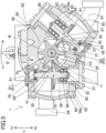
- FIG. 5 a front sectional view taken along line V-V in FIG. 4 .
- the front-back direction and the left-right direction are the horizontal directions.
- the up-down direction is the vertical direction (V).
- the screw compressor (1) includes a shaft (10), a screw rotor (20), a first gate rotor (30), a second gate rotor (35), a motor (40), and a casing (50).
- the screw compressor (1) includes a front cover (70), a front bearing (71), a front bearing holder (72), a rear bearing holder (73), a rear bearing (74), a spacer (75), a snap ring (76), a holding member (77), an intermediate bearing (78), a first proximal gate bearing (79), a first distal gate bearing (80), a first proximal gate bearing holder (81), a first distal gate bearing holder (82), a second proximal gate bearing (83), a second distal gate bearing (84), a second proximal gate bearing holder (85), and a second distal gate bearing holder (86).
- the screw compressor (1) includes a first slide valve (87), a first valve movement mechanism (88), a second slide valve (89), a second valve movement mechanism (90), a first cap (91), a gasket (92) as a first seal member, a second cap (93), a first cap-side discharge passage (94), a first discharge pipe (95), a silencer (96), a second cap-side discharge passage (97), and a second discharge pipe (98).
- a center axis (O) of the shaft (10) extends horizontally in the front-back direction.
- a direction in which the center axis (O) of the shaft (10) extends will be referred to as an axial direction (X).
- the axial direction (X) is the front-back direction.
- the screw compressor (1) is placed horizontally.
- a front side in the axial direction (X) is referred to as a front side (Xa) which is a first side in the axial direction (X).
- a rear side in the axial direction (X) is referred to as a rear side (Xb) which is a second side in the axial direction (X).
- the rear side (Xb) in the axial direction (X) is opposite to the front side (Xa) in the axial direction (X).
- a radial direction (R) of the screw compressor (1) is orthogonal to the axial direction (X).
- a side far from the center axis (O) in the radial direction (R) is referred to as a radially outer side or outside (Ra) in the radial direction (R).
- a side closer the center axis (O) in the radial direction (R) is referred to as a radially inner side or inside (Rb) in the radial direction (R).
- the up-down direction which is parallel to the radial direction (R), coincides with the vertical direction (V).
- An upper side in the vertical direction (V) is referred to as an upper side (above) (Va).
- a lower side in the vertical direction (V) is referred to as a lower side (below) (Vb).
- a circumferential direction ( ⁇ ) of the screw compressor (1) is a direction about the center axis (O).
- the screw rotor (20) is coupled to the shaft (10) and rotates together with the shaft (10).
- the screw rotor (20) extends in the axial direction (X), like the shaft (10).
- the screw rotor (20) includes a plurality of screw grooves (21), a front rotary seal (22), and a rear rotary seal (23).
- the screw rotor (20) is made of, for example, metal.
- the screw grooves (21) are provided in the middle of the outer periphery of the screw rotor (20) in the axial direction (X).
- the screw grooves (21) are arranged in the axial direction (X).
- the screw grooves (21) are helical grooves.
- a front end of the outer periphery of the screw rotor (20) in the axial direction (X) serves as the front rotary seal (22).
- a rear end of the outer periphery of the screw rotor (20) in the axial direction (X) serves as the rear rotary seal (23).
- the front rotary seal (22) and the rear rotary seal (23) have no screw grooves (21).
- the first gate rotor (30) is arranged outward of the screw rotor (20) in the radial direction (R).
- the first gate rotor (30) is disposed on the left of the screw rotor (20).
- the first gate rotor (30) includes a first gate shaft (31) and a first gate (32).
- the first gate rotor (30) is made of, for example, resin.
- the first gate shaft (31) extends in the vertical direction (V).
- the first gate (32) is fixed to the middle of the first gate shaft (31).
- the first gate (32) is substantially disc-shaped and concentric with the first gate shaft (31).
- the first gate (32) has a plurality of first gate teeth on the outer periphery.
- the first gate teeth of the first gate (32) of the first gate rotor (30) mesh with the screw grooves (21) of the screw rotor (20).
- the first gate (32) has a gate radius (r).
- the gate radius (r) is a radius of the first gate (32).
- the gate radius (r) is half the diameter of the first gate (32).
- the gate radius (r) is a distance from the center to outer periphery of the first gate (32).
- the second gate rotor (35) is arranged radially outside (Ra) of the screw rotor (20).
- the second gate rotor (35) is disposed on the lower (Vb) right side of the screw rotor (20).
- the second gate rotor (35) includes a second gate shaft (36) and a second gate (37).
- the second gate rotor (35) is made of, for example, resin.
- the second gate shaft (36) extends obliquely to the vertical direction (V).
- the second gate shaft (36) extends to the right as it goes upward (Va).
- the second gate (37) is fixed to the middle of the second gate shaft (36).
- the second gate (37) is substantially disc-shaped and concentric with the second gate shaft (36).
- the second gate (37) has a plurality of second gate teeth on the outer periphery.
- the second gate teeth of the second gate (37) of the second gate rotor (35) mesh with the screw grooves (21) of the screw rotor (20).
- the second gate (37) has a gate radius (r).
- the gate radius (r) is a radius of the second gate (37).
- the gate radius (r) is half the diameter of the second gate (37).
- the gate radius (r) is a distance from the center to outer periphery of the second gate (37).
- the motor (40) includes a motor rotor (41) and a motor stator (42).
- the motor rotor (41) is coupled to the shaft (10) and rotates together with the shaft (10).
- the motor rotor (41) is disposed on the front side (Xa) of the screw rotor (20) in the axial direction (X).
- the motor stator (42) is fixed to an inner wall of a casing (50), which will be described later, with a fastener (not shown).
- the motor rotor (41) and the motor stator (42) face each other in the radial direction (R) with a predetermined gap between them.
- the casing (50) has a substantially cylindrical shape. As illustrated in FIG. 4 , a front opening (50a) is provided at the front end of the casing (50). A rear opening (50b) is provided at the rear end of the casing (50).
- the casing (50) is divided in the axial direction (X) into a motor housing (51) on the front side (Xa) in the axial direction (X) and a compression chamber forming portion (52) on the rear side (Xb) in the axial direction (X) by a partition wall (53).
- the motor housing (51) of the casing (50) has a motor chamber (54).
- the motor chamber (54) is a cavity formed in the casing (50).
- the motor chamber (54) houses the shaft (10) and the motor (40).
- the motor chamber (54) houses the motor rotor (41) and motor stator (42) of the motor (40).
- the front end of the shaft (10) and the front end of the motor (40) protrude forward (Xa) of the motor chamber (54) through the front opening (50a).
- the front cover (70) covers the front opening (50a) of the casing (50).
- An inner protrusion (70a) is provided to protrude radially inward (Rb) from the inner wall of the front cover (70).
- the front bearing (71) is held by the inner protrusion (70a) of the front cover (70).
- the front bearing (71) rotatably supports the front end of the shaft (10) on the front cover (70).
- the front bearing holder (72) holds the front bearing (71) on the front cover (70).
- the compression chamber forming portion (52) of the casing (50) has a cylindrical wall (55).
- the screw rotor (20) is disposed in a front space in the cylindrical wall (55) in the axial direction (X).
- a rear bearing holder (73), which will be described later, is disposed in a rear space in the cylindrical wall (55) in the axial direction (X).
- an inner peripheral surface of the cylindrical wall (55) of the casing (50) covers the screw grooves (21) of the screw rotor (20) from outside (Ra) in the radial direction (R).
- the inner diameter of the cylindrical wall (55) is slightly larger than the outer diameter of the screw rotor (20).
- the cylindrical wall (55) is provided with a first slit (56) through which the first gate (32) passes.
- the cylindrical wall (55) is provided with a second slit (57) through which the second gate (37) passes.
- a portion (55a) of the inner peripheral surface of the cylindrical wall (55) of the casing (50) facing the front rotary seal (22) of the screw rotor (20) serves as a front stationary seal (hereinafter referred to as a "front stationary seal (55a)").
- a portion (55b) of the inner peripheral surface of the cylindrical wall (55) of the casing (50) facing the rear rotary seal (23) of the screw rotor (20) serves as a rear stationary seal (hereinafter referred to as a "rear stationary seal (55b)").
- the rear bearing holder (73) is disposed in the rear space in the cylindrical wall (55) in the axial direction (X) as illustrated in FIG. 4 .
- the rear bearing holder (73) is held on the inner peripheral surface of the cylindrical wall (55).
- the rear bearing holder (73) is substantially cylindrical.
- the rear bearing holder (73) includes a first portion (73a) extending in the axial direction (X) and a second portion (73b) extending inward (Rb) in the radial direction (R) from a front end of the first portion (73a).
- the two rear bearings (74) are arranged side by side in the axial direction (X).
- the rear bearings (74) are disposed between the first portion (73a) of the rear bearing holder (73) and the rear end of the shaft (10) in the radial direction (R).
- the rear bearing holder (73) holds the rear bearings (74).
- an inner peripheral surface of the first portion (73a) of the rear bearing holder (73) holds outer peripheral surfaces of the rear bearings (74).
- the rear bearings (74) support the rear end of the shaft (10) so that the shaft (10) is rotatable relative to the cylindrical wall (55) of the casing (50).
- the rear bearings (74) rotatably support the screw rotor (20) via the shaft (10).
- the spacer (75) is disposed between the second portion (73b) of the rear bearing holder (73) and the front one of the rear bearings (74).
- a snap ring (76) is disposed at the rear end of the rear one of the rear bearings (74). The snap ring (76) positions the rear bearings (74) in the axial direction (X).
- the holding member (77) covers the rear opening (50b) of the casing (50).
- the holding member (77) is plate-shaped.
- the holding member (77) has a thickness direction (t) in the axial direction (X).
- the holding member (77) is substantially disc-shaped.
- the holding member (77) is shorter in the axial direction (X) than in the radial direction (R).
- a front surface of the holding member (77) is in contact with the rear end of the first portion (73a) of the rear bearing holder (73).
- the holding member (77) presses the rear bearing holder (73) forward (Xa) in the axial direction (X).
- the holding member (77) holds the rear bearing holder (73) with respect to the cylindrical wall (55) of the casing (50).
- the partition wall (53) divides the casing (50) in the axial direction (X) into the motor housing (51) and the compression chamber forming portion (52) as illustrated in FIG. 4 .
- the partition wall (53) extends in the radial direction (R).
- the partition wall (53) is disposed on the front side (Xa) of the cylindrical wall (55) in the axial direction (X).
- a front surface of the partition wall (53) faces the motor chamber (54).
- a rear surface of the partition wall (53) faces the front end of the screw rotor (20).
- the partition wall (53) has a shaft through hole (53a).
- the shaft through hole (53a) penetrates the partition wall (53) in the axial direction (X).
- the shaft (10) passes the shaft through hole (53a) in the axial direction (X).
- the intermediate bearing (78) is disposed on the partition wall (53) in the shaft through hole (53a).
- the intermediate bearing (78) supports the shaft (10) so that the shaft (10) is rotatable relative to the partition wall (53) of the casing (50).
- the front bearing (71), the rear bearing (74), and the intermediate bearing (78) support the shaft (10) so that the shaft (10) is rotatable relative to the casing (50).
- the casing (50) rotatably holds the shaft (10).
- the casing (50) rotatably holds the screw rotor (20).
- the casing (50) rotatably holds the motor rotor (41).
- the casing (50) has a case outer wall (58) on the outside (Ra) in the radial direction (R).
- the case outer wall (58) is a wall on the outside (Ra) of the casing (50) in the radial direction (R).
- the casing (50) has a first gate rotor chamber (59).
- the first gate rotor chamber (59) is formed outside (Ra) the cylindrical wall (55) of the casing (50) in the radial direction (R).
- the first gate rotor chamber (59) is formed on the left of the cylindrical wall (55) of the casing (50).
- the first gate rotor chamber (59) and a first compression chamber (S 1) communicate with each other via the first slit (56).
- the first gate rotor (30) is housed in the first gate rotor chamber (59).
- the first gate rotor chamber (59) further houses the first proximal gate bearing (79), the first distal gate bearing (80), the first proximal gate bearing holder (81), and the first distal gate bearing holder (82).
- the first proximal gate bearing (79) is a single first proximal gate bearing (79).
- the first proximal gate bearing (79) rotatably supports a proximal end portion (an upper end portion) of the first gate shaft (31) of the first gate rotor (30).
- the first distal gate bearings (80) rotatably support a distal end portion (a lower end portion) of the first gate shaft (31) of the first gate rotor (30).
- the first proximal gate bearing holder (81) is disposed above (Va) the first gate rotor (30).
- the first proximal gate bearing holder (81) holds the first proximal gate bearing (79) with respect to the casing (50).
- the first proximal gate bearing holder (81) is detachable from the upper side (Va) of the first gate rotor chamber (59) of the casing (50).
- the first distal gate bearing holder (82) is disposed below (Vb) the first gate rotor (30).
- the first distal gate bearing holder (82) holds the first distal gate bearing (80).
- the first distal gate bearing holder (82) is detachable from the lower side (Vb) of the first gate rotor chamber (59) of the casing (50).
- a first gate opening (60) is formed in a left part of the case outer wall (58) of the casing (50).
- the first gate opening (60) communicates with the first gate rotor chamber (59).
- the casing (50) has a second gate rotor chamber (61).
- the second gate rotor chamber (61) is formed outside (Ra) the cylindrical wall (55) of the casing (50) in the radial direction (R).
- the second gate rotor chamber (61) is formed on the lower (Vb) right side of the cylindrical wall (55) of the casing (50).
- the second gate rotor chamber (61) and a second compression chamber (S2) communicate with each other via the second slit (57).
- the second gate rotor (35) is housed in the second gate rotor chamber (61).
- the second gate rotor chamber (61) further houses the second proximal gate bearing (83), the second distal gate bearing (84), the second proximal gate bearing holder (85), and the second distal gate bearing holder (86).
- the second proximal gate bearing (83) rotatably supports a proximal end portion (a lower left end portion) of the second gate shaft (36) of the second gate rotor (35).
- the second distal gate bearings (84) rotatably support a distal end portion (an upper right end portion) of the second gate shaft (36) of the second gate rotor (35).
- the second proximal gate bearing holder (85) is disposed on the lower (Vb) left side of the second gate rotor (35).
- the second proximal gate bearing holder (85) holds the second proximal gate bearings (83).
- the second proximal gate bearing holder (85) is detachable from the lower (Vb) left side of the second gate rotor chamber (61) of the casing (50).
- the second distal gate bearing holder (86) is disposed on the upper (Va) right side of the second gate rotor (35).
- the second distal gate bearing holder (86) holds the second distal gate bearings (84).
- the second distal gate bearing holder (86) is detachable from the upper (Va) right side of the second gate rotor chamber (61) of the casing (50).
- a second gate opening (62) is formed in a lower (Vb) right part of the case outer wall (58) of the casing (50).
- the second gate opening (62) communicates with the second gate rotor chamber (61).
- a first compression chamber (S1) is formed by the screw grooves (21) of the screw rotor (20), the first gate (32) of the first gate rotor (30), and the cylindrical wall (55) of the casing (50).
- the first compression chamber (S1) compresses a working fluid (W).
- a second compression chamber (S2) is formed by the screw grooves (21) of the screw rotor (20), the second gate (37) of the second gate rotor (35), and the cylindrical wall (55) of the casing (50).
- the second compression chamber (S2) compresses the working fluid (W).
- the working fluid (W) is, for example, a refrigerant gas.
- the first compression chamber (S1) is located above (Va) the center axis (O) of the screw rotor (20) (the shaft (10)) in the vertical direction (V).
- the first compression chamber (S1) is represented by a first range (S1a) in the circumferential direction ( ⁇ ) around the center axis (O)
- a major part of the whole first compression chamber (S1) is located above (Va) the center axis (O) in the vertical direction (V) (see FIG. 6 ).
- the second compression chamber (S2) is located below (Vb) the center axis (O) of the screw rotor (20) (the shaft (10)) in the vertical direction (V).
- the second compression chamber (S2) is represented by a second range (S2a) in the circumferential direction ( ⁇ ) around the center axis (O)
- a major part of the whole second compression chamber (S2) (the second range (S2a)) is located below (Vb) the center axis (O) in the vertical direction (V) (see FIG. 6 ).
- FIG. 6 shows the screw compressor (1) in a front sectional view taken along line VI-VI in FIG. 4 .
- a first case outlet (63) is formed in the left part of the case outer wall (58) of the casing (50).
- the working fluid (W) is discharged outside the casing (50) through the first case outlet (63).
- a second case outlet (64) is formed in a lower (Vb) right part of the case outer wall (58) of the casing (50).
- the working fluid (W) is discharged outside the casing (50) through the second case outlet (64).
- a first discharge port (65) is formed in a portion (55c) of the cylindrical wall (55) of the casing (50) facing the first compression chamber (S1).
- the first discharge port (65) is arranged on the upper (Va) left side of the screw rotor (20).
- the first discharge port (65) is formed in the inner peripheral surface of the cylindrical wall (55).
- the first discharge port (65) is formed in a substantially semicircular shape when viewed in the axial direction (X).
- the first discharge port (65) communicates with the first compression chamber (S1).
- a second discharge port (66) is formed in a portion (55d) of the cylindrical wall (55) of the casing (50) facing the second compression chamber (S2).
- the second discharge port (66) is arranged on the lower (Vb) right side of the screw rotor (20).
- the second discharge port (66) is formed in the inner peripheral surface of the cylindrical wall (55).
- the second discharge port (66) is formed in a substantially semicircular shape when viewed in the axial direction (X).
- the second discharge port (66) communicates with the second compression chamber (S2).
- the first case outlet (63) and the second case outlet (64) are located at different positions in the circumferential direction ( ⁇ ) of the screw rotor (20) (in the direction around the center axis (O)).
- the casing (50) is provided with a first connection passage (67).
- the first connection passage (67) is formed by opening a hole in the wall of the casing (50).
- the first connection passage (67) crosses the first gate rotor chamber (59) of the casing (50) in the left-right direction.
- the first connection passage (67) connects the first case outlet (63) and the first discharge port (65).
- the first discharge port (65) communicates with the first case outlet (63) via the first connection passage (67).
- the first connection passage (67) extends straight.
- the casing (50) is provided with a second connection passage (68).
- the second connection passage (67) is formed by opening a hole in the wall of the casing (50).
- the second connection passage (68) crosses the second gate rotor chamber (61) in the casing (50) obliquely with respect to the up-down direction and the left-right direction.
- the second connection passage (68) connects the second case outlet (64) and the second discharge port (66).
- the second discharge port (66) communicates with the second case outlet (64) via the second connection passage (68).
- the second connection passage (68) extends straight.
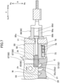
- FIG. 7 is a sectional view of the vicinity of the first discharge port (65) taken along line VII-VII in FIG. 6 .
- the first discharge port (65) is formed in the portion (55c) of the cylindrical wall (55) of the casing (50) facing the first compression chamber (S1).
- the first slide valve (87) moves in the axial direction (X) in the first discharge port (65).
- the first slide valve (87) moves in the axial direction (X)
- the position of the first slide valve (87) relative to the first compression chamber (S 1) changes.
- the first slide valve (87) moves in the axial direction (X) to adjust the opening degree (C) of the first discharge port (65).
- the first slide valve (87) comes to a front end position (Ja)
- the first slide valve (87) blocks a gap between the first compression chamber (S 1) and the first discharge port (65), reducing the opening degree (C) of the first discharge port (65).
- the first valve movement mechanism (88) causes the first slide valve (87) to move in the axial direction (X).
- the first valve movement mechanism (88) is a cylinder and piston mechanism.
- the first valve movement mechanism (88) includes a cylinder (88a), a piston (88b), and a rod (88c).
- the piston (88b) is disposed in the cylinder (88a).
- the rod (88c) extends from the front surface of the piston (88b) toward the front side (X) in the axial direction (X) and is connected to the rear end of the first slide valve (87).
- a pressure control chamber (88d) is formed in the cylinder (88a) on the rear side (Xb) of the piston (88b) in the axial direction (X).
- the first slide valve (87) moves to the front side (Xa) in the axial direction (X) together with the piston (88b) and the rod (88c).
- the first valve movement mechanism (88) biases the first slide valve (87) to the rear side (Xb) in the axial direction (X) with a spring.
- the second slide valve (89) moves in the axial direction (X) in the second discharge port (66).
- the second slide valve (89) moves in the axial direction (X) to adjust the opening degree (C) of the second discharge port (66).
- the second valve movement mechanism (90) causes the second slide valve (89) to move in the axial direction (X).
- the detailed structures of the second slide valve (89) and the second valve movement mechanism (90) are the same as those of the first slide valve (87) and the first valve movement mechanism (88).
- FIG. 8 is a sectional view illustrating the positional relationship between the first case outlet (63) and the first discharge port (65), with the first slide valve (87) removed.
- the first discharge port (65) includes a front end (65a) as a first end and a rear end (65b) as a second end.
- the front end (65a) is an end of the first discharge port (65) on the front side (Xa) in the axial direction (X).
- the rear end (65b) is an end of the first discharge port (65) on the rear side (Xb) in the axial direction (X).
- a position away from the front end (65a) of the first discharge port (65) toward the front side (Xa) in the axial direction (X) by the gate radius (r) of the first gate (32) is referred to as a front position (Ka) which is a first position.
- a position away from the rear end (65b) of the first discharge port (65) toward the rear side (Xb) in the axial direction (X) by the gate radius (r) of the first gate (32) is referred to as a rear position (Kb) which is a second position.
- the first case outlet (63) is located between the front position (Ka) and the rear position (Kb) in the axial direction (X).
- the first case outlet (63) is located to overlap with the first discharge port (65) in the axial direction (X).
- At least part of the opening width (B) of the first case outlet (63) in the axial direction (X) is within a range between the front position (Ka) and the rear position (Kb) in the axial direction (X).
- the first case outlet (63) is located closer to the first discharge port (65) than to the screw rotor (20) in the radial direction (R).
- a distance between the first case outlet (63) and the first discharge port (65) in the radial direction (R) is shorter than a distance between the first case outlet (63) and the screw rotor (20) in the radial direction (R).
- the positional relationship between the second case outlet (64) and the second discharge port (66) is substantially the same as the positional relationship between the first case outlet (63) and the first discharge port (65).
- the positional relationship between the second case outlet (64) and the second discharge port (66) is indicated by reference numerals in parentheses in FIG. 8 for the sake of simplicity, although it is slightly different in a strict sense.
- the same matters as those in the positional relationship between the first case outlet (63) and the first discharge port (65) may not be described in detail.
- the second discharge port (66) includes a front end (66a) as a first end and a rear end (66b) as a second end.
- the front end (66a) is an end of the second discharge port (66) on the front side (Xa) in the axial direction (X).
- the rear end (66b) is an end of the second discharge port (66) on the rear side (Xb) in the axial direction (X).
- a position away from the front end (66a) of the second discharge port (66) toward the front side (Xa) in the axial direction (X) by the gate radius (r) of the second gate (37) is referred to as a front position (Ka) which is a first position.
- a position away from the rear end (66b) of the second discharge port (66) toward the rear side (Xb) in the axial direction (X) by the gate radius (r) of the second gate (37) is referred to as a rear position (Kb) which is a second position.
- the second case outlet (64) is located between the front position (Ka) and the rear position (Kb) in the axial direction (X).
- the second case outlet (64) is located to overlap with the second discharge port (66) in the axial direction (X).
- the second case outlet (64) is located closer to the second discharge port (66) than to the screw rotor (20) in the radial direction (R).
- FIG. 9 is a sectional view taken along line IX-IX in FIG. 6 , illustrating the positional relationship between the first case outlet (63) and the first gate opening (60).
- the first gate shaft (31) and the first gate (32) of the first gate rotor (30) are visible through the first gate opening (60).
- the first case outlet (63) is arranged inside the first gate opening (60).
- the first case outlet (63) and the first gate opening (60) are covered with a common first cap (91).
- the first cap (91) is also referred to as a side cap.
- the first cap (91) is substantially disc-shaped.
- a first case-side mounting surface (58a) is provided on a peripheral portion of the first gate opening (60) of the case outer wall (58).
- the first cap (91) is mounted on the first case-side mounting surface (58a).
- the first case outlet (63) is flush with the first case-side mounting surface (58a) of the case outer wall (58) on which the first cap (91) is mounted.
- the first case outlet (63) being flush with the first case-side mounting surface (58a) means that the outer peripheral end of the first case outlet (63) and the first case-side mounting surface (58a) have almost no level difference.
- the level difference is preferably 1 mm or less, more preferably 0.5 mm or less, still more preferably 0.1 mm or less.
- a gasket (92) is disposed between the first case-side mounting surface (58a) and the first cap (91).
- the gasket (92) may be a sheet gasket or a spiral gasket.
- An O-ring may be used as the gasket (92).
- the first case-side mounting surface (58a) and the first cap (91) are sealed with the gasket (92).
- the positional relationship between the second case outlet (64) and the second gate opening (62) is substantially the same as the positional relationship between the first case outlet (63) and the first gate opening (60).
- the positional relationship between the second case outlet (64) and the second gate opening (62) is indicated by reference numerals in parentheses in FIG. 9 for the sake of simplicity, although it is slightly different in a strict sense.
- the same matters as those in the positional relationship between the first case outlet (63) and the first gate opening (60) may not be described in detail.
- the second case outlet (64) and the second gate opening (62) are covered with a common second cap (93).
- the second case outlet (64) is flush with a second case-side mounting surface (58b) of the case outer wall (58) on which the second cap (93) is mounted.
- the second case-side mounting surface (58b) and the second cap (93) are sealed with a gasket (92).
- the first cap (91) is provided with a first cap-side discharge passage (94).
- the first cap-side discharge passage (94) includes a hole (94a) and a pipe portion (94b).
- the hole (94a) of the first cap-side discharge passage (94) penetrates the first cap (91) in the radial direction (R).
- the hole (94a) of the first cap-side discharge passage (94) is connected to the first case outlet (63).
- the first cap-side discharge passage (94) communicates with the first case outlet (63).
- the pipe portion (94b) of the first cap-side discharge passage (94) is located outside (Ra) of the first cap (91) in the radial direction (R) and extends in the radial direction (R).
- the first cap (91) and the first cap-side discharge passage (94) are formed integrally.
- first discharge pipe (95) is connected to an end of the first cap-side discharge passage (94).
- first discharge pipe (95) is connected to the first case outlet (63) via the first cap-side discharge passage (94).
- the first discharge pipe (95) communicates with the first cap-side discharge passage (94). That is, the first discharge pipe (95) communicates with the first case outlet (63) via the first cap-side discharge passage (94).
- the other end of the first discharge pipe (95) is connected to a second inlet (69c) described later.
- the first discharge pipe (95) is provided with a silencer (96). Specifically, the silencer (96) is wound around the outer periphery of the first discharge pipe (95).
- the silencer (96) is made of, for example, a sponge or polyurethane.
- the second cap (93) is provided with a second cap-side discharge passage (97).
- the second cap-side discharge passage (97) includes a hole (97a) and a pipe portion (97b).
- the hole (97a) of the second cap-side discharge passage (97) penetrates the second cap (93) in the radial direction (R).
- the hole (97a) of the second cap-side discharge passage (97) is connected to the second case outlet (64).
- the second cap-side discharge passage (97) communicates with the second case outlet (64).
- the pipe portion (97b) of the second cap-side discharge passage (97) is located outside (Ra) of the second cap (93) in the radial direction (R) and extends in the radial direction (R).
- the second cap (93) and the second cap-side discharge passage (97) are formed integrally.
- the second discharge pipe (98) is connected to an end of the second cap-side discharge passage (97).
- the second discharge pipe (98) is connected to the second case outlet (64) via the second cap-side discharge passage (97).
- the second discharge pipe (98) communicates with the second cap-side discharge passage (97). That is, the second discharge pipe (98) communicates with the second case outlet (64) via the second cap-side discharge passage (97).
- the other end of the second discharge pipe (98) is connected to, for example, a condenser in the refrigerant circuit.
- the second discharge pipe (98) is provided with a silencer (96). Specifically, the silencer (96) is wound around the outer periphery of the second discharge pipe (98).
- a first inlet (69a) is provided in an upper portion of the case outer wall (58) of the compression chamber forming portion (52) of the casing (50).
- the first inlet (69a) communicates with the first compression chamber (S1) via a first suction passage (69b) provided in the cylindrical wall (55).
- the case outer wall (58) of the motor housing (51) of the casing (50) is provided with a second inlet (69c).
- the second inlet (69c) communicates with the motor chamber (54) via the second suction passage (69d).
- the screw compressor (1) is a two-stage screw compressor.
- the first compression chamber (S1) compresses the working fluid (W) at a first pressure (P1) to an intermediate pressure (Pm) higher than the first pressure (P1).
- the second compression chamber (S2) compresses the working fluid (W) at the intermediate pressure (Pm) to a second pressure (P2) higher than the intermediate pressure (Pm).
- the first compression chamber (S 1) is also referred to as a low-stage compression chamber.
- the second compression chamber (S2) is also referred to as a high-stage compression chamber.
- the first pressure (P1) is also referred to as a low pressure.
- the second pressure (P2) is also referred to as a high pressure.
- the working fluid (W) flows through the first inlet (69a), the first suction passage (69b), the first compression chamber (S 1), the first discharge port (65), the first connection passage (67), the first case outlet (63), the first cap-side discharge passage (94), the first discharge pipe (95), the second inlet (69c), the second suction passage (69d), the motor chamber (54) as an intermediate chamber (Sm), the second compression chamber (S2), the second discharge port (66), the second connection passage (68), the second case outlet (64), the second cap-side discharge passage (97), and the second discharge pipe (98) in this order.
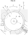
- FIG. 10 shows the screw compressor (1) in a front sectional view taken along line X-X in FIG. 4 .
- the front stationary seal (55a) on the inner peripheral surface of the cylindrical wall (55) of the casing (50) and the front rotary seal (22) of the screw rotor (20) slide against each other with a minute clearance left between them in the radial direction (R).
- the front stationary seal (55a) is disposed above (Va) the center axis (O) in the vertical direction (V).
- the front stationary seal (55a) and the front rotary seal (22) slide against each other above (Va) the center axis (O) in the vertical direction (V).
- the front stationary seal (55a) and the front rotary seal (22) seal the motor chamber (54) (the intermediate chamber (Sm)) and the first compression chamber (S1).
- the motor chamber (54) sealed with the front stationary seal (55a) and the front rotary seal (22) does not communicate with the first compression chamber (S1).
- the working fluid (W) is required to flow from the motor chamber (54) to the second compression chamber (S2), not from the motor chamber (54) to the first compression chamber (S1).
- the front stationary seal (55a) and the front rotary seal (22) block the flow of the working fluid (W) from the motor chamber (54) to the first compression chamber (S1).
- FIG. 11 shows the screw compressor (1) in a front sectional view taken along line XI-XI in FIG. 4 .
- the partition wall (53) of the casing (50) has a communication hole (53b).
- the communication hole (53b) penetrates the partition wall (53) in the axial direction (X).
- the communication hole (53b) constitutes a communication passage (F).
- the communication passage (F) includes the communication hole (53b).
- the communication passage (F) is disposed below (Vb) the center axis (O) in the vertical direction (V).
- the communication passage (F) allows the motor chamber (54) and the second compression chamber (S2) to communicate with (be connected to) each other.
- the motor chamber (54) communicates with the second compression chamber (S2) via the communication passage (F).
- the communication passage (F) includes an inclined portion (Fa).
- the inclined portion (Fa) is inclined upward from the motor chamber (54) on the front side (Xa) in the axial direction (X) toward the second compression chamber (S2) on the rear side (Xb) in the axial direction (X).
- FIG. 12 illustrates the positional relationship between a rotor (A) and the communication passage (F) in a sectional view.
- the rotor (A) includes the shaft (10), the screw rotor (20), and the motor rotor (41).
- the outermost diameter (DA) of the rotor (A) is the larger one of the outermost diameter (D20) of the screw rotor (20) and the outermost diameter (D41) of the motor rotor (41).
- the outermost diameter (D41) of the motor rotor (41) is larger than the outermost diameter (D20) of the screw rotor (20), and thus, the outermost diameter (DA) of the rotor (A) is the outermost diameter (D41) of the motor rotor (41).
- a lower end (Fb) of the communication passage (F) is located below (Vb) the outermost diameter (DA) of the rotor (A) in the vertical direction (V).
- an oil sump (G) is formed by an inner bottom surface (50c) of the casing (50) on the lower side (Vb) in the vertical direction (V).
- Oil (g) is stored in the oil sump (G).
- the oil (g) is contained in the working fluid (W) as mist and is separated by an oil separator (disposed outside the screw compressor (1), not shown) to be stored in the oil sump (G).
- the height of the oil level (G0) of the oil (g) in the oil sump (G) in the vertical direction (V) substantially coincides with the lower end (Fb) of the communication passage (F).
- the case outlet (63, 64) is formed in the case outer wall (58) outside (Ra) in the radial direction (R).
- the case outlet (63, 64) is located between the first position (Ka) and the second position (Kb) in the axial direction (X).
- the case outlet (63, 64) and the discharge port (65, 66) are not greatly spaced from each other in the axial direction (X).
- the case outlet (63, 64) is easily located near the discharge port (65, 66) in the axial direction (X).
- the fluid (W) is less likely to change its direction from the radial direction (R) to the axial direction (X) while flowing from the discharge port (65, 66) to the case outlet (63, 64).
- the fluid (W) compressed in the compression chamber (S 1, S2) flows outside (Ra) in the radial direction (R) from the compression chamber (S 1, S2) to the discharge port (65, 66), and most of the fluid (W) flows outside (Ra) in the radial direction (R) without changing its direction to the axial direction (X) and is discharged out of the casing (50) via the case outlet (63, 64).
- the fluid (W) compressed in the compression chamber (S 1, S2) is less likely to cause pressure loss until the fluid (W) is discharged out of the casing (50) via the discharge port (65, 66) and the case outlet (63, 64).
- the pressure loss of the fluid (W) in the screw compressor (1) can be reduced.
- the gate rotor chamber (59, 61) that houses the gate rotor (30, 35) is usually disposed near the discharge port (65, 66) in the axial direction (X).
- the cap (91, 93) covering the gate opening (60, 62) is also usually disposed near the discharge port (65, 66) in the axial direction (X).
- the fact that the case outlet (63, 64) is covered with the cap (91, 93) together with the gate opening (60, 62) means that the case outlet (63, 64) is located near the discharge port (65, 66) in the axial direction (X).
- the cap (91, 93) is provided with the cap-side discharge passage (94, 97) communicating with the case outlet (63, 64), allowing the fluid (W) to flow from the casing (50) toward the cap (91, 93).
- the case outlet (63, 64) is flush with the case-side mounting surface (58a, 58b).
- sealing the case-side mounting surface (58a, 58b) and the cap (91, 93) with the first seal member (92) can keep the fluid (W) discharged from the case outlet (63, 64) from leaking from a clearance between the case-side mounting surface (58a, 58b) and the cap (91, 93).
- the case outlet (63, 64) is located to overlap with the discharge port (65, 66) in the axial direction (X), allowing the case outlet (63, 64) to be located closer to the discharge port (65, 66) in the axial direction (X). This is advantageous in keeping the fluid (W) that has flowed outward (Ra) in the radial direction (R) from the compression chamber (S1, S2) to the discharge port (65, 66) from changing its direction to the axial direction (X) before reaching the case outlet (63, 64).
- connection passage (67, 68) extending straight is advantageous in reducing the pressure loss of the fluid (W) flowing through the connection passage (67, 68).
- Providing the silencer (96) for the discharge pipe (95, 98) is advantageous in reducing noise caused by the fluid (W) flowing through the discharge pipe (95, 98).
- the holding member (77) that presses the rear bearing holder (73) in the axial direction (X) is plate-shaped and has a thickness direction (t) in the axial direction (X). This is advantageous in reducing the dimension of the screw compressor (1) in the axial direction (X).
- the slide valve (87, 89) adjusts the opening degree (C) of the discharge port (S 1, S2), allowing easy adjustment of an apparent volume of the compression chamber (S 1, S2).
- the first case outlet (63) and the second case outlet (64) are located at different positions in the circumferential direction ( ⁇ ). Thus, both of the first case outlet (63) and the second case outlet (64) can be located between the first position (Ka) and the second position (Kb) in the axial direction (X) without interfering with each other.
- the first compression chamber (S 1) and the second compression chamber (S2) are spaced from each other not in the axial direction (X) but in the radial direction (R), advantageously reducing the dimension of the screw compressor (1) in the axial direction (X).
- the case outlet (63, 64) and the discharge port (65, 66) are hardly spaced from each other in the axial direction (X), advantageously reducing the dimension of the screw compressor (1) in the axial direction (X).
- the screw compressor (1) is a two-stage screw compressor, allowing two stage compression of the fluid (W) in the first compression chamber (S 1) and the second compression chamber (S2).
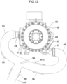
- FIG. 13 is a view corresponding to FIG. 3 , illustrating the screw compressor (1) of the second embodiment in a front view.
- the screw compressor (1) is not a two-stage compressor.
- the first discharge pipe (95) and the second discharge pipe (98) merge with each other at a merge portion (99).
- One end of a merge pipe (100) is connected to the merge portion (99).
- the first discharge pipe (95) and the second discharge pipe (98) communicate with the merge pipe (100) at the merge portion (99).
- the other end of the merge pipe (100) is connected to, for example, a condenser in the refrigerant circuit.
- the pulsations (U) of the fluids (W) are made to have opposite phases so that the pulsations (U) of the fluids (W) cancel each other.
- the opening degrees (C) of the discharge ports (65, 66), the lengths and diameters of the connection passages (67, 68), the diameters of the case outlets (63, 64), the lengths and diameters of the cap-side discharge passages (94, 97), and the lengths and diameters of the discharge pipes (95, 98) are adjusted.
- the first discharge pipe (95) is provided with a silencer (96).
- the second discharge pipe (98) is provided with a silencer (96).
- the merge pipe (100) is provided with a silencer (96).
- This embodiment is advantageous in reducing noise and vibration caused by the pulsation (U) of the fluid (W).
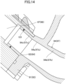
- FIG. 14 shows a cap-side discharge passage (94, 97) according to the third embodiment.
- the cap-side discharge passage (94, 97) includes a hole (94a, 97a), a pipe (94b, 97b), and a cap-side insertion pipe (94c, 97c).
- the cap-side insertion pipe (94c, 97c) of the cap-side discharge passage (94, 97) is located inside (Rb) the cap (91, 93) in the radial direction (R), and extends in the radial direction (R).
- the cap-side insertion pipe (94c, 97c) is inserted into the case outlet (63, 64).
- An O-ring (101) as a second seal member is provided on the outer periphery of the cap-side insertion pipe (94c, 97c).
- the case outlet (63, 64) and the cap-side insertion pipe (94c, 97c) are sealed with the O-ring (101).
- the fluid (W) discharged from the case outlet (63, 64) can be kept from leaking outside before reaching the cap-side discharge passage (94, 97).
- the case outlet (63, 64) may not overlap with the discharge port (65, 66) in the axial direction (X), and may be shifted from the discharge port (65, 66) in the axial direction (X) within a range between the front position (Ka) and the rear position (Kb).
- the cap (91, 93) and the cap-side discharge passage (94, 97) may not be formed integrally and may be formed of separate members.
- the case outlet (63, 64) may be disposed at a position different from the gate opening (60, 62).
- the case outlet (63, 64) may not be covered with the cap (91, 93).
- connection passage (67, 68) may not extend straight and may be bent in the axial direction (X), the radial direction (R), or the circumferential direction ( ⁇ ).
- the plate-shaped holding member (77) may be replaced with a cover.
- the first case outlet (63) and the second case outlet (64) may be located at the same position in the circumferential direction ( ⁇ ) as long as the first case outlet (63) and the second case outlet (64) are within the range between the front position (Ka) and the rear position (Kb) in the axial direction.
- first compression chamber (S 1) and the second compression chamber (S2) are provided, but the present disclosure is not limited to this example.
- the number of compression chambers may be one or three or more.
Landscapes
- Engineering & Computer Science (AREA)
- Mechanical Engineering (AREA)
- General Engineering & Computer Science (AREA)
- Applications Or Details Of Rotary Compressors (AREA)
Abstract
Description
- The present disclosure relates to a screw compressor.
- Various techniques about a screw compressor are disclosed as in Patent Document 1, for example.
- Patent Document 1:
Japanese Unexamined Patent Publication No. 2014-025435 - A screw compressor of this type includes a screw rotor, a gate rotor, and a casing. The screw rotor extends in an axial direction and has screw grooves formed in its outer periphery. The gate rotor is provided with a gate. The gate of the gate rotor meshes with the screw groove of the screw rotor. The casing rotatably holds the screw rotor and covers the screw rotor from radially outside.
- The screw rotor, the gate rotor, and the casing form a compression chamber for compressing a fluid. A discharge port is formed in a portion of the casing facing the compression chamber. The discharge port is located radially outward of the compression chamber. A discharge cover is attached to one side of the casing in the axial direction. The discharge cover is provided with an outlet.
- In the screw compressor disclosed in Patent Document 1, the discharge cover is interposed between the discharge port and the outlet, making the discharge port and the outlet inevitably spaced apart from each other in the axial direction. Thus, a fluid compressed in the compression chamber flows radially outward from the compression chamber toward the discharge port, changes the direction to flow in the axial direction inside the casing to reach the discharge cover, and is discharged outside of the discharge cover through the outlet.
- In the screw compressor disclosed in Patent Document 1, the fluid is forced to change its direction from the radial direction to the axial direction on the way from the discharge port to the outlet, resulting in a pressure loss while the fluid compressed in the compression chamber is discharged to the outside via the discharge port and the outlet.
- An object of the present disclosure is to reduce a fluid pressure loss in a screw compressor.
- A first aspect of the present disclosure is directed to a screw compressor (1). The screw compressor (1) includes: a screw rotor (20) having a screw groove (21) and extending in an axial direction (X); a gate rotor (30, 35) having a gate (32, 37) that meshes with the screw groove (21); and a casing (50) rotatably holding the screw rotor (20) and covering the screw rotor (20) from outside (Ra) in a radial direction (R) orthogonal to the axial direction (X). The screw rotor (20), the gate rotor (30, 35), and the casing (50) form a compression chamber (S1, S2) that compresses a fluid (W). A case outlet (63, 64) through which the fluid (W) is discharged is formed in a case outer wall (58) of the casing (50) outside (Ra) in the radial direction (R). A discharge port (65, 66) communicating with the case outlet (63, 64) is formed in a portion (55c, 55d) of the casing (50) facing the compression chamber (S1, S2). The discharge port (65, 66) has a first end (65a, 66a) on a first side (Xa) in the axial direction (X) and a second end (65b, 66b) on a second side (Xb) opposite to the first side (Xa) in the axial direction (X). The case outlet (63, 64) is located between a first position (Ka) away from the first end (65a, 66a) toward the first side (Xa) in the axial direction (X) by a radius (r) of the gate (32, 37) and a second position (Kb) away from the second end (65b, 66b) toward the second side (Xb) in the axial direction (X) by the radius (r) of the gate (32, 37). The case outlet (63, 64) is located closer to the discharge port (65, 66) than to the screw rotor (20) in the radial direction (R).
- According to the first aspect, the case outlet (63, 64) is formed in the case outer wall (58) outside (Ra) in the radial direction (R). The case outlet (63, 64) is located between the first position (Ka) and the second position (Kb) in the axial direction (X). The case outlet (63, 64) and the discharge port (65, 66) are not greatly spaced from each other in the axial direction (X). The case outlet (63, 64) is easily located near the discharge port (65, 66) in the axial direction (X).
- The fluid (W) is less likely to change its direction from the radial direction (R) to the axial direction (X) while flowing from the discharge port (65, 66) to the case outlet (63, 64). The fluid (W) compressed in the compression chamber (S 1, S2) flows outward (Ra) in the radial direction (R) from the compression chamber (S 1, S2) to the discharge port (65, 66), and most of the fluid (W) flows outward (Ra) in the radial direction (R) without changing its direction to the axial direction (X) and is discharged out of the casing (50) via the case outlet (63, 64).
- The fluid (W) compressed in the compression chamber (S 1, S2) is less likely to cause pressure loss until the fluid (W) is discharged out of the casing (50) via the discharge port (65, 66) and the case outlet (63, 64). Thus, the pressure loss of the fluid (W) in the screw compressor (1) can be reduced.
- A second aspect of the present disclosure is an embodiment of the first aspect. In the second aspect, the gate rotor (30, 35) is housed in a gate rotor chamber (59, 61) provided in the casing (50), the case outer wall is provided with a gate opening (60, 62) communicating with the gate rotor chamber (59, 61), the case outlet (63, 64) and the gate opening (60, 62) are covered with a cap (91, 93), and the cap (91, 93) is provided with a cap-side discharge passage (94, 97) communicating with the case outlet (63, 64).
- The gate rotor chamber (59, 61) that houses the gate rotor (30, 35) is usually disposed near the discharge port (65, 66) in the axial direction (X). The cap (91, 93) covering the gate opening (60, 62) is also usually disposed near the discharge port (65, 66) in the axial direction (X). The fact that the case outlet (63, 64) is covered with the cap (91, 93) together with the gate opening (60, 62) means that the case outlet (63, 64) is located near the discharge port (65, 66) in the axial direction (X). The cap (91, 93) is provided with the cap-side discharge passage (94, 97) communicating with the case outlet (63, 64), allowing the fluid (W) to flow from the casing (50) toward the cap (91, 93).
- A third aspect of the present disclosure is an embodiment of the second aspect. In the third aspect, the case outlet (63, 64) is flush with a case-side mounting surface (58a, 58b) of the case outer wall (58) on which the cap (91, 93) is mounted, and the case-side mounting surface (58a, 58b) and the cap (91, 93) are sealed with a first seal member (92).
- According to the third aspect, the case outlet (63, 64) is flush with the case-side mounting surface (58a, 58b). Thus, sealing the case-side mounting surface (58a, 58b) and the cap (91, 93) with the first seal member (92) can keep the fluid (W) discharged from the case outlet (63, 64) from leaking from a clearance between the case-side mounting surface (58a, 58b) and the cap (91, 93).
- A fourth aspect of the present disclosure is an embodiment of the second aspect. In the fourth aspect, the cap-side discharge passage (94, 97) includes a cap-side insertion pipe (94c, 97c) inserted into the case outlet (63, 64), and the case outlet (63, 64) and the cap-side insertion pipe (94c, 97c) are sealed with a second seal member (101).
- According to the fourth aspect, the fluid (W) discharged from the case outlet (63, 64) can be kept from leaking outside before reaching the cap-side discharge passage (94, 97).
- A fifth aspect of the present disclosure is an embodiment of any one of the first to fourth aspects. In the fifth aspect, the case outlet (63, 64) is located to overlap with the discharge port (65, 66) in the axial direction (X).
- According to the fifth aspect, the case outlet (63, 64) can be located closer to the discharge port (65, 66) in the axial direction (X). This is advantageous in keeping the fluid (W) that has flowed outward (Ra) in the radial direction (R) from the compression chamber (S 1, S2) to the discharge port (65, 66) from changing its direction to the axial direction (X) before reaching the case outlet (63, 64).
- A sixth aspect of the present disclosure is an embodiment of any one of the first to fifth aspects. In the sixth aspect, the casing (50) is provided with a connection passage (67, 68) that connects the case outlet (63, 64) and the discharge port (65, 66), and the connection passage (67, 68) extends straight.
- According to the sixth aspect, the connection passage (67, 68) extending straight is advantageous in reducing the pressure loss of the fluid (W) flowing through the connection passage (67, 68).
- A seventh aspect of the present disclosure is an embodiment of any one of the first to sixth aspects. In the seventh aspect, a discharge pipe (95, 98) is connected to the case outlet (63, 64), and the discharge pipe (95, 98) is provided with a silencer (96).
- According to the seventh aspect, providing the silencer (96) for the discharge pipe (95, 98) is advantageous in reducing noise caused by the fluid (W) flowing through the discharge pipe (95, 98).
- An eighth aspect of the present disclosure is an embodiment of any one of the first to seventh aspects. In the eighth aspect, the screw compressor (1) further includes: a bearing holder (73) that holds a bearing (74) supporting the screw rotor (20); and a holding member (77) that presses the bearing holder (73) in the axial direction (X). The holding member (77) is plate-shaped and has a thickness direction (t) in the axial direction (X).
- According to the eighth aspect, the holding member (77) is plate-shaped and has the thickness direction (t) in the axial direction (X). This is advantageous in reducing the dimension of the screw compressor (1) in the axial direction (X).
- A ninth aspect of the present disclosure is an embodiment of any one of the first to eighth aspects. In the ninth aspect, the screw compressor (1) further includes: a slide valve (87, 89) that moves in the axial direction (X) to adjust an opening degree (C) of the discharge port (S1, S2).
- According to the ninth aspect, the slide valve (87, 89) adjusts the opening degree (C) of the discharge port (65, 66), allowing easy adjustment of an apparent volume of the compression chamber (S1, S2).
- A tenth aspect of the present disclosure is an embodiment of any one of the first to ninth aspects. In the screw compressor (1) of the tenth aspect, the gate rotor (30, 35) includes a first gate rotor (30) and a second gate rotor (35), the compression chamber (S1, S2) includes a first compression chamber (S1) formed by the screw rotor (20), the first gate rotor (30), and the casing (50) and a second compression chamber (S2) formed by the screw rotor (20), the second gate rotor (35), and the casing (50), the case outlet (63, 64) includes a first case outlet (63) and a second case outlet (64) formed in the case outer wall (58), the discharge port (65, 66) includes a first discharge port (65) formed in a portion (55c) of the casing (50) facing the first compression chamber (S1) and a second discharge port (66) formed in a portion (55d) of the casing (50) facing the second compression chamber (S2), the first discharge port (65) communicates with the first case outlet (63), the second discharge port (66) communicates with the second case outlet (64), and the first case outlet (63) and the second case outlet (64) are located at different positions in a circumferential direction (θ) of the screw rotor (20).
- According to the tenth aspect, the first case outlet (63) and the second case outlet (64) are located at different positions in the circumferential direction (θ). Thus, both of the first case outlet (63) and the second case outlet (64) can be located between the first position (Ka) and the second position (Kb) in the axial direction (X) without interfering with each other.
- An eleventh aspect of the present disclosure is an embodiment of any one of the first to tenth aspects. In the eleventh aspect, the gate rotor (30, 35) includes a first gate rotor (30) and a second gate rotor (35), the compression chamber (S1, S2) includes a first compression chamber (S1) formed by the screw rotor (20), the first gate rotor (30), and the casing (50) and a second compression chamber (S2) formed by the screw rotor (20), the second gate rotor (35), and the casing (50), the case outlet (63, 64) includes a first case outlet (63) and a second case outlet (64) formed in the case outer wall (58), the discharge port (65, 66) includes a first discharge port (65) formed in a portion (55c) of the casing (50) facing the first compression chamber (S1) and a second discharge port (66) formed in a portion (55d) of the casing (50) facing the second compression chamber (S2), the first discharge port (65) communicates with the first case outlet (63), the second discharge port (66) communicates with the second case outlet (64), a first discharge pipe (95) is connected to the first case outlet (63), a second discharge pipe (98) is connected to the second case outlet (64), the first discharge pipe (95) and the second discharge pipe (98) merge with each other at a merge portion (99), and a pulsation (U) of the fluid (W) flowing from the first discharge port (65) to the merge portion (99) through the first case outlet (63) and the first discharge pipe (95) and a pulsation (U) of the fluid (W) flowing from the second discharge port (66) to the merge portion (99) through the second case outlet (64) and the second discharge pipe (98) cancel each other.
- The eleventh aspect is advantageous in reducing noise and vibration caused by the pulsation (U) of the fluid (W).
- A twelfth aspect of the present disclosure is an embodiment of the tenth aspect. In the twelfth aspect, the first compression chamber (S 1) compresses the fluid (W) at a first pressure (P1) to an intermediate pressure (Pm) higher than the first pressure (P1), the second compression chamber (S2) compresses the fluid (W) at the intermediate pressure (Pm) to a second pressure (S2) higher than the intermediate pressure (Pm), and the fluid (W) flows through the first compression chamber (S 1), the first discharge port (65), the first case outlet (63), the second compression chamber (S2), the second discharge port (66), and the second case outlet (64) in this order.
- According to the twelfth aspect, the fluid (W) can be compressed in at least two stages in the first compression chamber (S 1) and the second compression chamber (S2).
-
-
FIG. 1 is a right side view of a screw compressor according to a first embodiment. -
FIG. 2 is a left side view of a screw compressor (1). -
FIG. 3 is a front view of the screw compressor (1). -
FIG. 4 is a right side sectional view of the screw compressor (1) taken along line IV-IV inFIG. 3 . -
FIG. 5 is a front sectional view of the screw compressor (1) taken along line V-V inFIG. 4 . -
FIG. 6 is a front sectional view of the screw compressor (1) taken along line VI-VI inFIG. 4 . -
FIG. 7 is a sectional view of the vicinity of a first discharge port (65) taken along line VII-VII inFIG. 6 . -
FIG. 8 is a sectional view illustrating the positional relationship between a first case outlet (63) and a first discharge port (65), with a first slide valve (87) removed. -
FIG. 9 is a sectional view in the direction of arrows on line IX-IX inFIG. 6 , illustrating the positional relationship between the first case outlet (63) and a first gate opening (60). -
FIG. 10 is a front sectional view of the screw compressor (1) taken along line X-X inFIG. 4 . -
FIG. 11 is a front sectional view of the screw compressor (1) taken along line XI-XI inFIG. 4 . -
FIG. 12 is a right side sectional view illustrating the positional relationship between a rotor (A) and a communication passage (F). -
FIG. 13 is a front view corresponding toFIG. 3 , illustrating a screw compressor (1) of a second embodiment. -
FIG. 14 is a view of a cap-side discharge passage (94, 97) according to a third embodiment. - A screw compressor (1) according to a first embodiment will be described below. The screw compressor (1) is applied to a refrigeration apparatus such as an air conditioner. The refrigeration apparatus includes a refrigerant circuit in which a refrigerant circulates. The screw compressor (1) compresses the refrigerant in the refrigerant circuit. The refrigerant circulates in the refrigerant circuit to cause a vapor compression refrigeration cycle.
-
FIGS. 1 to 5 show the screw compressor (1) of the first embodiment. In the following description, the left side ofFIG. 1 may be referred to as the front side, the right side ofFIG. 1 as the rear side, the upper side ofFIG. 1 as the upper side, the lower side ofFIG. 1 as the lower side, the back side of the sheet inFIG. 1 as the left side, and the front side of the sheet inFIG. 1 as the right side.FIG. 1 is a right side view,FIG. 2 a left side view,FIG. 3 a front view,FIG. 4 a right side sectional view taken along line IV-IV inFIG. 3 , andFIG. 5 a front sectional view taken along line V-V inFIG. 4 . The front-back direction and the left-right direction are the horizontal directions. The up-down direction is the vertical direction (V). - The screw compressor (1) includes a shaft (10), a screw rotor (20), a first gate rotor (30), a second gate rotor (35), a motor (40), and a casing (50).
- The screw compressor (1) includes a front cover (70), a front bearing (71), a front bearing holder (72), a rear bearing holder (73), a rear bearing (74), a spacer (75), a snap ring (76), a holding member (77), an intermediate bearing (78), a first proximal gate bearing (79), a first distal gate bearing (80), a first proximal gate bearing holder (81), a first distal gate bearing holder (82), a second proximal gate bearing (83), a second distal gate bearing (84), a second proximal gate bearing holder (85), and a second distal gate bearing holder (86).
- The screw compressor (1) includes a first slide valve (87), a first valve movement mechanism (88), a second slide valve (89), a second valve movement mechanism (90), a first cap (91), a gasket (92) as a first seal member, a second cap (93), a first cap-side discharge passage (94), a first discharge pipe (95), a silencer (96), a second cap-side discharge passage (97), and a second discharge pipe (98).
- As illustrated in
FIG. 4 , a center axis (O) of the shaft (10) extends horizontally in the front-back direction. A direction in which the center axis (O) of the shaft (10) extends will be referred to as an axial direction (X). The axial direction (X) is the front-back direction. The screw compressor (1) is placed horizontally. A front side in the axial direction (X) is referred to as a front side (Xa) which is a first side in the axial direction (X). A rear side in the axial direction (X) is referred to as a rear side (Xb) which is a second side in the axial direction (X). The rear side (Xb) in the axial direction (X) is opposite to the front side (Xa) in the axial direction (X). - A radial direction (R) of the screw compressor (1) is orthogonal to the axial direction (X). A side far from the center axis (O) in the radial direction (R) is referred to as a radially outer side or outside (Ra) in the radial direction (R). A side closer the center axis (O) in the radial direction (R) is referred to as a radially inner side or inside (Rb) in the radial direction (R). The up-down direction, which is parallel to the radial direction (R), coincides with the vertical direction (V). An upper side in the vertical direction (V) is referred to as an upper side (above) (Va). A lower side in the vertical direction (V) is referred to as a lower side (below) (Vb). A circumferential direction (θ) of the screw compressor (1) is a direction about the center axis (O).
- The screw rotor (20) is coupled to the shaft (10) and rotates together with the shaft (10). The screw rotor (20) extends in the axial direction (X), like the shaft (10). The screw rotor (20) includes a plurality of screw grooves (21), a front rotary seal (22), and a rear rotary seal (23). The screw rotor (20) is made of, for example, metal.
- The screw grooves (21) are provided in the middle of the outer periphery of the screw rotor (20) in the axial direction (X). The screw grooves (21) are arranged in the axial direction (X). The screw grooves (21) are helical grooves.
- A front end of the outer periphery of the screw rotor (20) in the axial direction (X) serves as the front rotary seal (22). A rear end of the outer periphery of the screw rotor (20) in the axial direction (X) serves as the rear rotary seal (23). The front rotary seal (22) and the rear rotary seal (23) have no screw grooves (21).
- As illustrated in
FIG. 5 , the first gate rotor (30) is arranged outward of the screw rotor (20) in the radial direction (R). The first gate rotor (30) is disposed on the left of the screw rotor (20). - The first gate rotor (30) includes a first gate shaft (31) and a first gate (32). The first gate rotor (30) is made of, for example, resin. The first gate shaft (31) extends in the vertical direction (V). The first gate (32) is fixed to the middle of the first gate shaft (31). The first gate (32) is substantially disc-shaped and concentric with the first gate shaft (31). The first gate (32) has a plurality of first gate teeth on the outer periphery. The first gate teeth of the first gate (32) of the first gate rotor (30) mesh with the screw grooves (21) of the screw rotor (20).
- The first gate (32) has a gate radius (r). The gate radius (r) is a radius of the first gate (32). The gate radius (r) is half the diameter of the first gate (32). The gate radius (r) is a distance from the center to outer periphery of the first gate (32).
- As illustrated in
FIG. 5 , the second gate rotor (35) is arranged radially outside (Ra) of the screw rotor (20). The second gate rotor (35) is disposed on the lower (Vb) right side of the screw rotor (20). - The second gate rotor (35) includes a second gate shaft (36) and a second gate (37). The second gate rotor (35) is made of, for example, resin. The second gate shaft (36) extends obliquely to the vertical direction (V). The second gate shaft (36) extends to the right as it goes upward (Va). The second gate (37) is fixed to the middle of the second gate shaft (36). The second gate (37) is substantially disc-shaped and concentric with the second gate shaft (36). The second gate (37) has a plurality of second gate teeth on the outer periphery. The second gate teeth of the second gate (37) of the second gate rotor (35) mesh with the screw grooves (21) of the screw rotor (20).
- The second gate (37) has a gate radius (r). The gate radius (r) is a radius of the second gate (37). The gate radius (r) is half the diameter of the second gate (37). The gate radius (r) is a distance from the center to outer periphery of the second gate (37).
- As illustrated in
FIG. 4 , the motor (40) includes a motor rotor (41) and a motor stator (42). The motor rotor (41) is coupled to the shaft (10) and rotates together with the shaft (10). The motor rotor (41) is disposed on the front side (Xa) of the screw rotor (20) in the axial direction (X). The motor stator (42) is fixed to an inner wall of a casing (50), which will be described later, with a fastener (not shown). The motor rotor (41) and the motor stator (42) face each other in the radial direction (R) with a predetermined gap between them. - As illustrated in
FIGS. 1 to 4 , the casing (50) has a substantially cylindrical shape. As illustrated inFIG. 4 , a front opening (50a) is provided at the front end of the casing (50). A rear opening (50b) is provided at the rear end of the casing (50). The casing (50) is divided in the axial direction (X) into a motor housing (51) on the front side (Xa) in the axial direction (X) and a compression chamber forming portion (52) on the rear side (Xb) in the axial direction (X) by a partition wall (53). - As illustrated in
FIG. 4 , the motor housing (51) of the casing (50) has a motor chamber (54). The motor chamber (54) is a cavity formed in the casing (50). The motor chamber (54) houses the shaft (10) and the motor (40). The motor chamber (54) houses the motor rotor (41) and motor stator (42) of the motor (40). The front end of the shaft (10) and the front end of the motor (40) protrude forward (Xa) of the motor chamber (54) through the front opening (50a). - The front cover (70) covers the front opening (50a) of the casing (50). An inner protrusion (70a) is provided to protrude radially inward (Rb) from the inner wall of the front cover (70). The front bearing (71) is held by the inner protrusion (70a) of the front cover (70). The front bearing (71) rotatably supports the front end of the shaft (10) on the front cover (70). The front bearing holder (72) holds the front bearing (71) on the front cover (70).
- As illustrated in
FIG. 4 , the compression chamber forming portion (52) of the casing (50) has a cylindrical wall (55). The screw rotor (20) is disposed in a front space in the cylindrical wall (55) in the axial direction (X). A rear bearing holder (73), which will be described later, is disposed in a rear space in the cylindrical wall (55) in the axial direction (X). - As illustrated in
FIG. 5 , an inner peripheral surface of the cylindrical wall (55) of the casing (50) covers the screw grooves (21) of the screw rotor (20) from outside (Ra) in the radial direction (R). The inner diameter of the cylindrical wall (55) is slightly larger than the outer diameter of the screw rotor (20). The cylindrical wall (55) is provided with a first slit (56) through which the first gate (32) passes. The cylindrical wall (55) is provided with a second slit (57) through which the second gate (37) passes. - As illustrated in
FIG. 4 , a portion (55a) of the inner peripheral surface of the cylindrical wall (55) of the casing (50) facing the front rotary seal (22) of the screw rotor (20) serves as a front stationary seal (hereinafter referred to as a "front stationary seal (55a)"). A portion (55b) of the inner peripheral surface of the cylindrical wall (55) of the casing (50) facing the rear rotary seal (23) of the screw rotor (20) serves as a rear stationary seal (hereinafter referred to as a "rear stationary seal (55b)"). - As described above, the rear bearing holder (73) is disposed in the rear space in the cylindrical wall (55) in the axial direction (X) as illustrated in
FIG. 4 . The rear bearing holder (73) is held on the inner peripheral surface of the cylindrical wall (55). The rear bearing holder (73) is substantially cylindrical. The rear bearing holder (73) includes a first portion (73a) extending in the axial direction (X) and a second portion (73b) extending inward (Rb) in the radial direction (R) from a front end of the first portion (73a). - There are two rear bearings (74). The two rear bearings (74) are arranged side by side in the axial direction (X). The rear bearings (74) are disposed between the first portion (73a) of the rear bearing holder (73) and the rear end of the shaft (10) in the radial direction (R). The rear bearing holder (73) holds the rear bearings (74). Specifically, an inner peripheral surface of the first portion (73a) of the rear bearing holder (73) holds outer peripheral surfaces of the rear bearings (74).
- The rear bearings (74) support the rear end of the shaft (10) so that the shaft (10) is rotatable relative to the cylindrical wall (55) of the casing (50). The rear bearings (74) rotatably support the screw rotor (20) via the shaft (10).
- The spacer (75) is disposed between the second portion (73b) of the rear bearing holder (73) and the front one of the rear bearings (74). A snap ring (76) is disposed at the rear end of the rear one of the rear bearings (74). The snap ring (76) positions the rear bearings (74) in the axial direction (X).
- The holding member (77) covers the rear opening (50b) of the casing (50). The holding member (77) is plate-shaped. The holding member (77) has a thickness direction (t) in the axial direction (X). The holding member (77) is substantially disc-shaped. The holding member (77) is shorter in the axial direction (X) than in the radial direction (R).
- A front surface of the holding member (77) is in contact with the rear end of the first portion (73a) of the rear bearing holder (73). The holding member (77) presses the rear bearing holder (73) forward (Xa) in the axial direction (X). The holding member (77) holds the rear bearing holder (73) with respect to the cylindrical wall (55) of the casing (50).
- As described above, the partition wall (53) divides the casing (50) in the axial direction (X) into the motor housing (51) and the compression chamber forming portion (52) as illustrated in
FIG. 4 . The partition wall (53) extends in the radial direction (R). The partition wall (53) is disposed on the front side (Xa) of the cylindrical wall (55) in the axial direction (X). A front surface of the partition wall (53) faces the motor chamber (54). A rear surface of the partition wall (53) faces the front end of the screw rotor (20). - The partition wall (53) has a shaft through hole (53a). The shaft through hole (53a) penetrates the partition wall (53) in the axial direction (X). The shaft (10) passes the shaft through hole (53a) in the axial direction (X).
- The intermediate bearing (78) is disposed on the partition wall (53) in the shaft through hole (53a). The intermediate bearing (78) supports the shaft (10) so that the shaft (10) is rotatable relative to the partition wall (53) of the casing (50).
- The front bearing (71), the rear bearing (74), and the intermediate bearing (78) support the shaft (10) so that the shaft (10) is rotatable relative to the casing (50). The casing (50) rotatably holds the shaft (10). The casing (50) rotatably holds the screw rotor (20). The casing (50) rotatably holds the motor rotor (41).
- As illustrated in
FIGS. 3 to 5 , the casing (50) has a case outer wall (58) on the outside (Ra) in the radial direction (R). The case outer wall (58) is a wall on the outside (Ra) of the casing (50) in the radial direction (R). - As illustrated in
FIG. 5 , the casing (50) has a first gate rotor chamber (59). The first gate rotor chamber (59) is formed outside (Ra) the cylindrical wall (55) of the casing (50) in the radial direction (R). The first gate rotor chamber (59) is formed on the left of the cylindrical wall (55) of the casing (50). The first gate rotor chamber (59) and a first compression chamber (S 1) communicate with each other via the first slit (56). - The first gate rotor (30) is housed in the first gate rotor chamber (59). The first gate rotor chamber (59) further houses the first proximal gate bearing (79), the first distal gate bearing (80), the first proximal gate bearing holder (81), and the first distal gate bearing holder (82).
- The first proximal gate bearing (79) is a single first proximal gate bearing (79). The first proximal gate bearing (79) rotatably supports a proximal end portion (an upper end portion) of the first gate shaft (31) of the first gate rotor (30). There are two first distal gate bearings (80). The first distal gate bearings (80) rotatably support a distal end portion (a lower end portion) of the first gate shaft (31) of the first gate rotor (30).
- The first proximal gate bearing holder (81) is disposed above (Va) the first gate rotor (30). The first proximal gate bearing holder (81) holds the first proximal gate bearing (79) with respect to the casing (50). The first proximal gate bearing holder (81) is detachable from the upper side (Va) of the first gate rotor chamber (59) of the casing (50).
- The first distal gate bearing holder (82) is disposed below (Vb) the first gate rotor (30). The first distal gate bearing holder (82) holds the first distal gate bearing (80). The first distal gate bearing holder (82) is detachable from the lower side (Vb) of the first gate rotor chamber (59) of the casing (50).
- A first gate opening (60) is formed in a left part of the case outer wall (58) of the casing (50). The first gate opening (60) communicates with the first gate rotor chamber (59).
- As illustrated in
FIG. 5 , the casing (50) has a second gate rotor chamber (61). The second gate rotor chamber (61) is formed outside (Ra) the cylindrical wall (55) of the casing (50) in the radial direction (R). The second gate rotor chamber (61) is formed on the lower (Vb) right side of the cylindrical wall (55) of the casing (50). The second gate rotor chamber (61) and a second compression chamber (S2) communicate with each other via the second slit (57). - The second gate rotor (35) is housed in the second gate rotor chamber (61). The second gate rotor chamber (61) further houses the second proximal gate bearing (83), the second distal gate bearing (84), the second proximal gate bearing holder (85), and the second distal gate bearing holder (86).
- There is a single second proximal gate bearing (83). The second proximal gate bearing (83) rotatably supports a proximal end portion (a lower left end portion) of the second gate shaft (36) of the second gate rotor (35). There are three second distal gate bearings (84). The second distal gate bearings (84) rotatably support a distal end portion (an upper right end portion) of the second gate shaft (36) of the second gate rotor (35).
- The second proximal gate bearing holder (85) is disposed on the lower (Vb) left side of the second gate rotor (35). The second proximal gate bearing holder (85) holds the second proximal gate bearings (83). The second proximal gate bearing holder (85) is detachable from the lower (Vb) left side of the second gate rotor chamber (61) of the casing (50).
- The second distal gate bearing holder (86) is disposed on the upper (Va) right side of the second gate rotor (35). The second distal gate bearing holder (86) holds the second distal gate bearings (84). The second distal gate bearing holder (86) is detachable from the upper (Va) right side of the second gate rotor chamber (61) of the casing (50).
- A second gate opening (62) is formed in a lower (Vb) right part of the case outer wall (58) of the casing (50). The second gate opening (62) communicates with the second gate rotor chamber (61).
- As illustrated in
FIG. 5 , a first compression chamber (S1) is formed by the screw grooves (21) of the screw rotor (20), the first gate (32) of the first gate rotor (30), and the cylindrical wall (55) of the casing (50). The first compression chamber (S1) compresses a working fluid (W). A second compression chamber (S2) is formed by the screw grooves (21) of the screw rotor (20), the second gate (37) of the second gate rotor (35), and the cylindrical wall (55) of the casing (50). The second compression chamber (S2) compresses the working fluid (W). The working fluid (W) is, for example, a refrigerant gas. - The first compression chamber (S1) is located above (Va) the center axis (O) of the screw rotor (20) (the shaft (10)) in the vertical direction (V). Specifically, suppose the first compression chamber (S1) is represented by a first range (S1a) in the circumferential direction (θ) around the center axis (O), a major part of the whole first compression chamber (S1) (the first range (S1a)) is located above (Va) the center axis (O) in the vertical direction (V) (see
FIG. 6 ). - The second compression chamber (S2) is located below (Vb) the center axis (O) of the screw rotor (20) (the shaft (10)) in the vertical direction (V). Specifically, suppose the second compression chamber (S2) is represented by a second range (S2a) in the circumferential direction (θ) around the center axis (O), a major part of the whole second compression chamber (S2) (the second range (S2a)) is located below (Vb) the center axis (O) in the vertical direction (V) (see
FIG. 6 ). -
FIG. 6 shows the screw compressor (1) in a front sectional view taken along line VI-VI inFIG. 4 . A first case outlet (63) is formed in the left part of the case outer wall (58) of the casing (50). The working fluid (W) is discharged outside the casing (50) through the first case outlet (63). A second case outlet (64) is formed in a lower (Vb) right part of the case outer wall (58) of the casing (50). The working fluid (W) is discharged outside the casing (50) through the second case outlet (64). - As illustrated in
FIG. 6 , a first discharge port (65) is formed in a portion (55c) of the cylindrical wall (55) of the casing (50) facing the first compression chamber (S1). The first discharge port (65) is arranged on the upper (Va) left side of the screw rotor (20). The first discharge port (65) is formed in the inner peripheral surface of the cylindrical wall (55). The first discharge port (65) is formed in a substantially semicircular shape when viewed in the axial direction (X). The first discharge port (65) communicates with the first compression chamber (S1). - A second discharge port (66) is formed in a portion (55d) of the cylindrical wall (55) of the casing (50) facing the second compression chamber (S2). The second discharge port (66) is arranged on the lower (Vb) right side of the screw rotor (20). The second discharge port (66) is formed in the inner peripheral surface of the cylindrical wall (55). The second discharge port (66) is formed in a substantially semicircular shape when viewed in the axial direction (X). The second discharge port (66) communicates with the second compression chamber (S2).
- As illustrated in
FIG. 6 , the first case outlet (63) and the second case outlet (64) are located at different positions in the circumferential direction (θ) of the screw rotor (20) (in the direction around the center axis (O)). - As illustrated in
FIG. 6 , the casing (50) is provided with a first connection passage (67). The first connection passage (67) is formed by opening a hole in the wall of the casing (50). The first connection passage (67) crosses the first gate rotor chamber (59) of the casing (50) in the left-right direction. The first connection passage (67) connects the first case outlet (63) and the first discharge port (65). The first discharge port (65) communicates with the first case outlet (63) via the first connection passage (67). The first connection passage (67) extends straight. - The casing (50) is provided with a second connection passage (68). The second connection passage (67) is formed by opening a hole in the wall of the casing (50). The second connection passage (68) crosses the second gate rotor chamber (61) in the casing (50) obliquely with respect to the up-down direction and the left-right direction. The second connection passage (68) connects the second case outlet (64) and the second discharge port (66). The second discharge port (66) communicates with the second case outlet (64) via the second connection passage (68). The second connection passage (68) extends straight.
-
FIG. 7 is a sectional view of the vicinity of the first discharge port (65) taken along line VII-VII inFIG. 6 . As described above, the first discharge port (65) is formed in the portion (55c) of the cylindrical wall (55) of the casing (50) facing the first compression chamber (S1). The first slide valve (87) moves in the axial direction (X) in the first discharge port (65). - When the first slide valve (87) moves in the axial direction (X), the position of the first slide valve (87) relative to the first compression chamber (S 1) changes. The first slide valve (87) moves in the axial direction (X) to adjust the opening degree (C) of the first discharge port (65). When the first slide valve (87) comes to a front end position (Ja), the first slide valve (87) blocks a gap between the first compression chamber (S 1) and the first discharge port (65), reducing the opening degree (C) of the first discharge port (65). When the first slide valve (87) comes to a rear end position (Jb) (indicated by the two dot chain line), the gap is generated between the first compression chamber (S 1) and the first discharge port (65), increasing the opening degree (C) of the first discharge port (65).
- The first valve movement mechanism (88) causes the first slide valve (87) to move in the axial direction (X). The first valve movement mechanism (88) is a cylinder and piston mechanism. The first valve movement mechanism (88) includes a cylinder (88a), a piston (88b), and a rod (88c). The piston (88b) is disposed in the cylinder (88a). The rod (88c) extends from the front surface of the piston (88b) toward the front side (X) in the axial direction (X) and is connected to the rear end of the first slide valve (87).
- A pressure control chamber (88d) is formed in the cylinder (88a) on the rear side (Xb) of the piston (88b) in the axial direction (X). When a high pressure is introduced into the pressure control chamber (88d), the first slide valve (87) moves to the front side (Xa) in the axial direction (X) together with the piston (88b) and the rod (88c). Although not shown, the first valve movement mechanism (88) biases the first slide valve (87) to the rear side (Xb) in the axial direction (X) with a spring.
- Although not described in detail, the second slide valve (89) (see
FIG. 6 ) moves in the axial direction (X) in the second discharge port (66). The second slide valve (89) moves in the axial direction (X) to adjust the opening degree (C) of the second discharge port (66). The second valve movement mechanism (90) (seeFIGS. 1 and2 ) causes the second slide valve (89) to move in the axial direction (X). The detailed structures of the second slide valve (89) and the second valve movement mechanism (90) are the same as those of the first slide valve (87) and the first valve movement mechanism (88). -
FIG. 8 is a sectional view illustrating the positional relationship between the first case outlet (63) and the first discharge port (65), with the first slide valve (87) removed. - As illustrated in
FIG. 8 , the first discharge port (65) includes a front end (65a) as a first end and a rear end (65b) as a second end. The front end (65a) is an end of the first discharge port (65) on the front side (Xa) in the axial direction (X). The rear end (65b) is an end of the first discharge port (65) on the rear side (Xb) in the axial direction (X). - A position away from the front end (65a) of the first discharge port (65) toward the front side (Xa) in the axial direction (X) by the gate radius (r) of the first gate (32) is referred to as a front position (Ka) which is a first position. A position away from the rear end (65b) of the first discharge port (65) toward the rear side (Xb) in the axial direction (X) by the gate radius (r) of the first gate (32) is referred to as a rear position (Kb) which is a second position.
- The first case outlet (63) is located between the front position (Ka) and the rear position (Kb) in the axial direction (X). The first case outlet (63) is located to overlap with the first discharge port (65) in the axial direction (X).
- At least part of the opening width (B) of the first case outlet (63) in the axial direction (X) is within a range between the front position (Ka) and the rear position (Kb) in the axial direction (X).
- As illustrated in
FIG. 6 , the first case outlet (63) is located closer to the first discharge port (65) than to the screw rotor (20) in the radial direction (R). A distance between the first case outlet (63) and the first discharge port (65) in the radial direction (R) is shorter than a distance between the first case outlet (63) and the screw rotor (20) in the radial direction (R). - The positional relationship between the second case outlet (64) and the second discharge port (66) is substantially the same as the positional relationship between the first case outlet (63) and the first discharge port (65). The positional relationship between the second case outlet (64) and the second discharge port (66) is indicated by reference numerals in parentheses in
FIG. 8 for the sake of simplicity, although it is slightly different in a strict sense. In the description of the positional relationship between the second case outlet (64) and the second discharge port (66), the same matters as those in the positional relationship between the first case outlet (63) and the first discharge port (65) may not be described in detail. - As illustrated in
FIG. 8 , the second discharge port (66) includes a front end (66a) as a first end and a rear end (66b) as a second end. The front end (66a) is an end of the second discharge port (66) on the front side (Xa) in the axial direction (X). The rear end (66b) is an end of the second discharge port (66) on the rear side (Xb) in the axial direction (X). - A position away from the front end (66a) of the second discharge port (66) toward the front side (Xa) in the axial direction (X) by the gate radius (r) of the second gate (37) is referred to as a front position (Ka) which is a first position. A position away from the rear end (66b) of the second discharge port (66) toward the rear side (Xb) in the axial direction (X) by the gate radius (r) of the second gate (37) is referred to as a rear position (Kb) which is a second position.
- The second case outlet (64) is located between the front position (Ka) and the rear position (Kb) in the axial direction (X). The second case outlet (64) is located to overlap with the second discharge port (66) in the axial direction (X).
- As illustrated in
FIG. 6 , the second case outlet (64) is located closer to the second discharge port (66) than to the screw rotor (20) in the radial direction (R). -
FIG. 9 is a sectional view taken along line IX-IX inFIG. 6 , illustrating the positional relationship between the first case outlet (63) and the first gate opening (60). - As illustrated in
FIGS. 6 and9 , the first gate shaft (31) and the first gate (32) of the first gate rotor (30) are visible through the first gate opening (60). The first case outlet (63) is arranged inside the first gate opening (60). - The first case outlet (63) and the first gate opening (60) are covered with a common first cap (91). The first cap (91) is also referred to as a side cap. The first cap (91) is substantially disc-shaped. A first case-side mounting surface (58a) is provided on a peripheral portion of the first gate opening (60) of the case outer wall (58). The first cap (91) is mounted on the first case-side mounting surface (58a). The first case outlet (63) is flush with the first case-side mounting surface (58a) of the case outer wall (58) on which the first cap (91) is mounted.
- The first case outlet (63) being flush with the first case-side mounting surface (58a) means that the outer peripheral end of the first case outlet (63) and the first case-side mounting surface (58a) have almost no level difference. The level difference is preferably 1 mm or less, more preferably 0.5 mm or less, still more preferably 0.1 mm or less.
- As illustrated in
FIG. 6 , a gasket (92) is disposed between the first case-side mounting surface (58a) and the first cap (91). The gasket (92) may be a sheet gasket or a spiral gasket. An O-ring may be used as the gasket (92). The first case-side mounting surface (58a) and the first cap (91) are sealed with the gasket (92). - The positional relationship between the second case outlet (64) and the second gate opening (62) is substantially the same as the positional relationship between the first case outlet (63) and the first gate opening (60). The positional relationship between the second case outlet (64) and the second gate opening (62) is indicated by reference numerals in parentheses in
FIG. 9 for the sake of simplicity, although it is slightly different in a strict sense. In the description of the positional relationship between the second case outlet (64) and the second gate opening (62), the same matters as those in the positional relationship between the first case outlet (63) and the first gate opening (60) may not be described in detail. - The second case outlet (64) and the second gate opening (62) are covered with a common second cap (93). The second case outlet (64) is flush with a second case-side mounting surface (58b) of the case outer wall (58) on which the second cap (93) is mounted. The second case-side mounting surface (58b) and the second cap (93) are sealed with a gasket (92).
- As illustrated in
FIG. 6 , the first cap (91) is provided with a first cap-side discharge passage (94). The first cap-side discharge passage (94) includes a hole (94a) and a pipe portion (94b). The hole (94a) of the first cap-side discharge passage (94) penetrates the first cap (91) in the radial direction (R). The hole (94a) of the first cap-side discharge passage (94) is connected to the first case outlet (63). The first cap-side discharge passage (94) communicates with the first case outlet (63). The pipe portion (94b) of the first cap-side discharge passage (94) is located outside (Ra) of the first cap (91) in the radial direction (R) and extends in the radial direction (R). The first cap (91) and the first cap-side discharge passage (94) are formed integrally. - One end of the first discharge pipe (95) is connected to an end of the first cap-side discharge passage (94). In other words, the first discharge pipe (95) is connected to the first case outlet (63) via the first cap-side discharge passage (94). The first discharge pipe (95) communicates with the first cap-side discharge passage (94). That is, the first discharge pipe (95) communicates with the first case outlet (63) via the first cap-side discharge passage (94). The other end of the first discharge pipe (95) is connected to a second inlet (69c) described later.
- The first discharge pipe (95) is provided with a silencer (96). Specifically, the silencer (96) is wound around the outer periphery of the first discharge pipe (95). The silencer (96) is made of, for example, a sponge or polyurethane.
- As illustrated in
FIG. 6 , the second cap (93) is provided with a second cap-side discharge passage (97). The second cap-side discharge passage (97) includes a hole (97a) and a pipe portion (97b). The hole (97a) of the second cap-side discharge passage (97) penetrates the second cap (93) in the radial direction (R). The hole (97a) of the second cap-side discharge passage (97) is connected to the second case outlet (64). The second cap-side discharge passage (97) communicates with the second case outlet (64). The pipe portion (97b) of the second cap-side discharge passage (97) is located outside (Ra) of the second cap (93) in the radial direction (R) and extends in the radial direction (R). The second cap (93) and the second cap-side discharge passage (97) are formed integrally. - One end of the second discharge pipe (98) is connected to an end of the second cap-side discharge passage (97). In other words, the second discharge pipe (98) is connected to the second case outlet (64) via the second cap-side discharge passage (97). The second discharge pipe (98) communicates with the second cap-side discharge passage (97). That is, the second discharge pipe (98) communicates with the second case outlet (64) via the second cap-side discharge passage (97). The other end of the second discharge pipe (98) is connected to, for example, a condenser in the refrigerant circuit. The second discharge pipe (98) is provided with a silencer (96). Specifically, the silencer (96) is wound around the outer periphery of the second discharge pipe (98).
- As illustrated in
FIG. 4 , a first inlet (69a) is provided in an upper portion of the case outer wall (58) of the compression chamber forming portion (52) of the casing (50). The first inlet (69a) communicates with the first compression chamber (S1) via a first suction passage (69b) provided in the cylindrical wall (55). - As illustrated in
FIG. 4 , the case outer wall (58) of the motor housing (51) of the casing (50) is provided with a second inlet (69c). The second inlet (69c) communicates with the motor chamber (54) via the second suction passage (69d). - The screw compressor (1) is a two-stage screw compressor. The first compression chamber (S1) compresses the working fluid (W) at a first pressure (P1) to an intermediate pressure (Pm) higher than the first pressure (P1). The second compression chamber (S2) compresses the working fluid (W) at the intermediate pressure (Pm) to a second pressure (P2) higher than the intermediate pressure (Pm). The first compression chamber (S 1) is also referred to as a low-stage compression chamber. The second compression chamber (S2) is also referred to as a high-stage compression chamber. The first pressure (P1) is also referred to as a low pressure. The second pressure (P2) is also referred to as a high pressure.
- The working fluid (W) flows through the first inlet (69a), the first suction passage (69b), the first compression chamber (S 1), the first discharge port (65), the first connection passage (67), the first case outlet (63), the first cap-side discharge passage (94), the first discharge pipe (95), the second inlet (69c), the second suction passage (69d), the motor chamber (54) as an intermediate chamber (Sm), the second compression chamber (S2), the second discharge port (66), the second connection passage (68), the second case outlet (64), the second cap-side discharge passage (97), and the second discharge pipe (98) in this order.
-
FIG. 10 shows the screw compressor (1) in a front sectional view taken along line X-X inFIG. 4 . As illustrated inFIGS. 4 and10 , the front stationary seal (55a) on the inner peripheral surface of the cylindrical wall (55) of the casing (50) and the front rotary seal (22) of the screw rotor (20) slide against each other with a minute clearance left between them in the radial direction (R). As illustrated inFIG. 10 , the front stationary seal (55a) is disposed above (Va) the center axis (O) in the vertical direction (V). The front stationary seal (55a) and the front rotary seal (22) slide against each other above (Va) the center axis (O) in the vertical direction (V). - As illustrated in
FIG. 4 , the front stationary seal (55a) and the front rotary seal (22) seal the motor chamber (54) (the intermediate chamber (Sm)) and the first compression chamber (S1). The motor chamber (54) sealed with the front stationary seal (55a) and the front rotary seal (22) does not communicate with the first compression chamber (S1). - As described above, the working fluid (W) is required to flow from the motor chamber (54) to the second compression chamber (S2), not from the motor chamber (54) to the first compression chamber (S1). The front stationary seal (55a) and the front rotary seal (22) block the flow of the working fluid (W) from the motor chamber (54) to the first compression chamber (S1).
-
FIG. 11 shows the screw compressor (1) in a front sectional view taken along line XI-XI inFIG. 4 . As illustrated inFIGS. 4 and11 , the partition wall (53) of the casing (50) has a communication hole (53b). The communication hole (53b) penetrates the partition wall (53) in the axial direction (X). - The communication hole (53b) constitutes a communication passage (F). In other words, the communication passage (F) includes the communication hole (53b). The communication passage (F) is disposed below (Vb) the center axis (O) in the vertical direction (V).
- The communication passage (F) allows the motor chamber (54) and the second compression chamber (S2) to communicate with (be connected to) each other. The motor chamber (54) communicates with the second compression chamber (S2) via the communication passage (F).
- The communication passage (F) includes an inclined portion (Fa). The inclined portion (Fa) is inclined upward from the motor chamber (54) on the front side (Xa) in the axial direction (X) toward the second compression chamber (S2) on the rear side (Xb) in the axial direction (X).
-
FIG. 12 illustrates the positional relationship between a rotor (A) and the communication passage (F) in a sectional view. The rotor (A) includes the shaft (10), the screw rotor (20), and the motor rotor (41). The outermost diameter (DA) of the rotor (A) is the larger one of the outermost diameter (D20) of the screw rotor (20) and the outermost diameter (D41) of the motor rotor (41). In this example, the outermost diameter (D41) of the motor rotor (41) is larger than the outermost diameter (D20) of the screw rotor (20), and thus, the outermost diameter (DA) of the rotor (A) is the outermost diameter (D41) of the motor rotor (41). - A lower end (Fb) of the communication passage (F) is located below (Vb) the outermost diameter (DA) of the rotor (A) in the vertical direction (V).
- As illustrated in
FIG. 12 , an oil sump (G) is formed by an inner bottom surface (50c) of the casing (50) on the lower side (Vb) in the vertical direction (V). Oil (g) is stored in the oil sump (G). The oil (g) is contained in the working fluid (W) as mist and is separated by an oil separator (disposed outside the screw compressor (1), not shown) to be stored in the oil sump (G). When the working fluid (W) flows at a sufficient flow rate, the height of the oil level (G0) of the oil (g) in the oil sump (G) in the vertical direction (V) substantially coincides with the lower end (Fb) of the communication passage (F). - According to this embodiment, the case outlet (63, 64) is formed in the case outer wall (58) outside (Ra) in the radial direction (R). The case outlet (63, 64) is located between the first position (Ka) and the second position (Kb) in the axial direction (X). The case outlet (63, 64) and the discharge port (65, 66) are not greatly spaced from each other in the axial direction (X). The case outlet (63, 64) is easily located near the discharge port (65, 66) in the axial direction (X).
- The fluid (W) is less likely to change its direction from the radial direction (R) to the axial direction (X) while flowing from the discharge port (65, 66) to the case outlet (63, 64). The fluid (W) compressed in the compression chamber (S 1, S2) flows outside (Ra) in the radial direction (R) from the compression chamber (S 1, S2) to the discharge port (65, 66), and most of the fluid (W) flows outside (Ra) in the radial direction (R) without changing its direction to the axial direction (X) and is discharged out of the casing (50) via the case outlet (63, 64).
- The fluid (W) compressed in the compression chamber (S 1, S2) is less likely to cause pressure loss until the fluid (W) is discharged out of the casing (50) via the discharge port (65, 66) and the case outlet (63, 64). Thus, the pressure loss of the fluid (W) in the screw compressor (1) can be reduced.
- The gate rotor chamber (59, 61) that houses the gate rotor (30, 35) is usually disposed near the discharge port (65, 66) in the axial direction (X). The cap (91, 93) covering the gate opening (60, 62) is also usually disposed near the discharge port (65, 66) in the axial direction (X). The fact that the case outlet (63, 64) is covered with the cap (91, 93) together with the gate opening (60, 62) means that the case outlet (63, 64) is located near the discharge port (65, 66) in the axial direction (X).
- The cap (91, 93) is provided with the cap-side discharge passage (94, 97) communicating with the case outlet (63, 64), allowing the fluid (W) to flow from the casing (50) toward the cap (91, 93).
- The case outlet (63, 64) is flush with the case-side mounting surface (58a, 58b). Thus, sealing the case-side mounting surface (58a, 58b) and the cap (91, 93) with the first seal member (92) can keep the fluid (W) discharged from the case outlet (63, 64) from leaking from a clearance between the case-side mounting surface (58a, 58b) and the cap (91, 93).
- The case outlet (63, 64) is located to overlap with the discharge port (65, 66) in the axial direction (X), allowing the case outlet (63, 64) to be located closer to the discharge port (65, 66) in the axial direction (X). This is advantageous in keeping the fluid (W) that has flowed outward (Ra) in the radial direction (R) from the compression chamber (S1, S2) to the discharge port (65, 66) from changing its direction to the axial direction (X) before reaching the case outlet (63, 64).
- The connection passage (67, 68) extending straight is advantageous in reducing the pressure loss of the fluid (W) flowing through the connection passage (67, 68).
- Providing the silencer (96) for the discharge pipe (95, 98) is advantageous in reducing noise caused by the fluid (W) flowing through the discharge pipe (95, 98).
- The holding member (77) that presses the rear bearing holder (73) in the axial direction (X) is plate-shaped and has a thickness direction (t) in the axial direction (X). This is advantageous in reducing the dimension of the screw compressor (1) in the axial direction (X).
- The slide valve (87, 89) adjusts the opening degree (C) of the discharge port (S 1, S2), allowing easy adjustment of an apparent volume of the compression chamber (S 1, S2).
- The first case outlet (63) and the second case outlet (64) are located at different positions in the circumferential direction (θ). Thus, both of the first case outlet (63) and the second case outlet (64) can be located between the first position (Ka) and the second position (Kb) in the axial direction (X) without interfering with each other.
- The first compression chamber (S 1) and the second compression chamber (S2) are spaced from each other not in the axial direction (X) but in the radial direction (R), advantageously reducing the dimension of the screw compressor (1) in the axial direction (X). In addition to the above configuration, the case outlet (63, 64) and the discharge port (65, 66) are hardly spaced from each other in the axial direction (X), advantageously reducing the dimension of the screw compressor (1) in the axial direction (X).
- When two or more case outlets (63, 64) are provided, the above configuration is more advantageous in terms of costs than when a single case outlet (63, 64) is provided.
- The screw compressor (1) is a two-stage screw compressor, allowing two stage compression of the fluid (W) in the first compression chamber (S 1) and the second compression chamber (S2).
- A screw compressor (1) according to a second embodiment will be described below. In the following description of the second embodiment, the same components as those of the above-described embodiment are denoted by the same reference numerals and are not described in detail in some cases.
FIG. 13 is a view corresponding toFIG. 3 , illustrating the screw compressor (1) of the second embodiment in a front view. - In this embodiment, the screw compressor (1) is not a two-stage compressor. The first discharge pipe (95) and the second discharge pipe (98) merge with each other at a merge portion (99). One end of a merge pipe (100) is connected to the merge portion (99). The first discharge pipe (95) and the second discharge pipe (98) communicate with the merge pipe (100) at the merge portion (99). The other end of the merge pipe (100) is connected to, for example, a condenser in the refrigerant circuit.
- A pulsation (U) of the fluid (W) flowing from the first discharge port (65) to the merge portion (99) through the first connection passage (67), the first case outlet (63), the first cap-side discharge passage (94), and the first discharge pipe (95) and a pulsation (U) of the fluid (W) flowing from the second discharge port (66) to the merge portion (99) through the second connection passage (68), the second case outlet (64), the second cap-side discharge passage (97), and the second discharge pipe (98) cancel each other.
- The pulsations (U) of the fluids (W) are made to have opposite phases so that the pulsations (U) of the fluids (W) cancel each other.
- For the cancelation of the pulsations (U) of the fluids (W) (making the pulsations (U) have the opposite phases), the opening degrees (C) of the discharge ports (65, 66), the lengths and diameters of the connection passages (67, 68), the diameters of the case outlets (63, 64), the lengths and diameters of the cap-side discharge passages (94, 97), and the lengths and diameters of the discharge pipes (95, 98) are adjusted.
- The first discharge pipe (95) is provided with a silencer (96). The second discharge pipe (98) is provided with a silencer (96). The merge pipe (100) is provided with a silencer (96).
- The other configurations are the same as those of the first embodiment.
- This embodiment is advantageous in reducing noise and vibration caused by the pulsation (U) of the fluid (W).
- A screw compressor (1) according to a third embodiment will be described below. In the following description of the third embodiment, the same components as those of the above-described embodiment are denoted by the same reference numerals and are not described in detail in some cases.
FIG. 14 shows a cap-side discharge passage (94, 97) according to the third embodiment. - The cap-side discharge passage (94, 97) includes a hole (94a, 97a), a pipe (94b, 97b), and a cap-side insertion pipe (94c, 97c). The cap-side insertion pipe (94c, 97c) of the cap-side discharge passage (94, 97) is located inside (Rb) the cap (91, 93) in the radial direction (R), and extends in the radial direction (R).
- The cap-side insertion pipe (94c, 97c) is inserted into the case outlet (63, 64). An O-ring (101) as a second seal member is provided on the outer periphery of the cap-side insertion pipe (94c, 97c). The case outlet (63, 64) and the cap-side insertion pipe (94c, 97c) are sealed with the O-ring (101).
- The other configurations are the same as those of the first embodiment.
- In this embodiment, the fluid (W) discharged from the case outlet (63, 64) can be kept from leaking outside before reaching the cap-side discharge passage (94, 97).
- The case outlet (63, 64) may not overlap with the discharge port (65, 66) in the axial direction (X), and may be shifted from the discharge port (65, 66) in the axial direction (X) within a range between the front position (Ka) and the rear position (Kb).
- The cap (91, 93) and the cap-side discharge passage (94, 97) may not be formed integrally and may be formed of separate members.
- The case outlet (63, 64) may be disposed at a position different from the gate opening (60, 62). The case outlet (63, 64) may not be covered with the cap (91, 93).
- The connection passage (67, 68) may not extend straight and may be bent in the axial direction (X), the radial direction (R), or the circumferential direction (θ).
- The plate-shaped holding member (77) may be replaced with a cover.
- The first case outlet (63) and the second case outlet (64) may be located at the same position in the circumferential direction (θ) as long as the first case outlet (63) and the second case outlet (64) are within the range between the front position (Ka) and the rear position (Kb) in the axial direction.
- In the above embodiments, two compression chambers, i.e., the first compression chamber (S 1) and the second compression chamber (S2), are provided, but the present disclosure is not limited to this example. The number of compression chambers may be one or three or more.
- While the embodiments have been described above, it will be understood that various changes in form and details can be made without departing from the spirit and scope of the claims. The elements of the above-described embodiments, variations, and other embodiments may be appropriately combined or replaced.
-
- O
- Center Axis
- X
- Axial Direction
- Xa
- Front Side (First Side)
- Xb
- Rear Side (Second Side)
- R
- Radial Direction
- Ra
- Radially Outer Side (Outside)
- Rb
- Radially Inner Side (Inside)
- V
- Vertical Direction
- Va
- Upper Side (Above)
- Vb
- Lower Side (Below)
- θ
- Circumferential Direction
- r
- Gate Radius
- t
- Thickness Direction
- W
- Working Fluid (Fluid)
- S1
- First Compression Chamber
- S2
- Second Compression Chamber
- Sm
- Intermediate Chamber
- P1
- First Pressure
- P2
- Second Pressure
- Pm
- Intermediate Pressure
- C
- Opening Degree
- Ka
- Front Position (First Position)
- Kb
- Rear Position (Second Position)
- F
- Communication Passage
- Fa
- Inclined Portion
- Fb
- Lower End
- A
- Rotor
- DA
- Outermost Diameter
- D20
- Outermost Diameter
- D41
- Outermost Diameter
- G
- Oil Sump
- G0
- Oil Level
- g
- Oil
- U
- Pulsation
- 1
- Screw Compressor
- 10
- Shaft
- 20
- Screw Rotor
- 21
- Screw Groove
- 22
- Front Rotary Seal
- 23
- Rear Rotary Seal
- 30
- First Gate Rotor
- 32
- First Gate
- 35
- Second Gate Rotor
- 37
- Second Gate
- 40
- Motor
- 41
- Motor Rotor
- 42
- Motor Stator
- 50
- Casing
- 53
- Partition Wall (Wall)
- 53b
- Communication Hole
- 54
- Motor Chamber
- 55
- Cylindrical Wall
- 55a
- Front Stationary Seal (Portion)
- 55b
- Rear Stationary Seal (Portion)
- 55c
- Portion
- 55d
- Portion
- 56
- First Slit
- 57
- Second Slit
- 58
- Case Outer Wall
- 58a
- First Case-Side Mounting Surface
- 58b
- Second Case-Side Mounting Surface
- 59
- First Gate Rotor Chamber
- 60
- First Gate Opening
- 61
- Second Gate Rotor Chamber
- 62
- Second Gate Opening
- 63
- First Case Outlet
- 64
- Second Case Outlet
- 65
- First Discharge Port
- 65a
- Front End (First End)
- 65b
- Rear End (Second End)
- 66
- Second Discharge Port
- 66a
- Front End (First End)
- 66b
- Rear End (Second End)
- 67
- First Connection Passage
- 68
- Second Connection Passage
- 69a
- First Inlet
- 69c
- Second Inlet
- 73
- Rear Bearing Holder (Bearing Holder)
- 74
- Rear Bearing (Bearing)
- 77
- Holding Member
- 87
- First Slide Valve
- 89
- Second Slide Valve
- 91
- First Cap
- 92
- Gasket (First Seal Member)
- 93
- Second Cap
- 94
- First Cap-Side Discharge Passage
- 94c
- Cap-Side Insertion Pipe
- 95
- First Discharge Pipe
- 96
- Silencer
- 97
- Second Cap-Side Discharge Passage
- 97c
- Cap-side Insertion Pipe
- 98
- Second Discharge Pipe
- 99
- Merge Portion
- 100
- Merge Pipe
- 101
- O-ring (Second Seal Member)
Claims (12)
- A screw compressor, comprising:a screw rotor (20) having a screw groove (21) and extending in an axial direction (X);a gate rotor (30, 35) having a gate (32, 37) that meshes with the screw groove (21); anda casing (50) rotatably holding the screw rotor (20) and covering the screw rotor (20) from outside (Ra) in a radial direction (R) orthogonal to the axial direction (X),the screw rotor (20), the gate rotor (30, 35), and the casing (50) forming a compression chamber (S1, S2) that compresses a fluid (W),a case outlet (63, 64) through which the fluid (W) is discharged being formed in a case outer wall (58) of the casing (50) outside (Ra) in the radial direction (R),a discharge port (65, 66) communicating with the case outlet (63, 64) being formed in a portion (55c, 55d) of the casing (50) facing the compression chamber (S1, S2),the discharge port (65, 66) having a first end (65a, 66a) on a first side (Xa) in the axial direction (X) and a second end (65b, 66b) on a second side (Xb) opposite to the first side (Xa) in the axial direction (X),the case outlet (63, 64) being located between a first position (Ka) away from the first end (65a, 66a) toward the first side (Xa) in the axial direction (X) by a radius (r) of the gate (32, 37) and a second position (Kb) away from the second end (65b, 66b) toward the second side (Xb) in the axial direction (X) by the radius (r) of the gate (32, 37),the case outlet (63, 64) being located closer to the discharge port (65, 66) than to the screw rotor (20) in the radial direction (R).
- The screw compressor of claim 1, whereinthe gate rotor (30, 35) is housed in a gate rotor chamber (59, 61) provided in the casing (50), the case outer wall (58) is provided with a gate opening (60, 62) communicating with the gate rotor chamber (59, 61),the case outlet (63, 64) and the gate opening (60, 62) are covered with a cap (91, 93), andthe cap (91, 93) is provided with a cap-side discharge passage (94, 97) communicating with the case outlet (63, 64).
- The screw compressor of claim 2, whereinthe case outlet (63, 64) is flush with a case-side mounting surface (58a, 58b) of the case outer wall (58) on which the cap (91, 93) is mounted, andthe case-side mounting surface (58a, 58b) and the cap (91, 93) are sealed with a first seal member (92).
- The screw compressor of claim 2, whereinthe cap-side discharge passage (94, 97) includes a cap-side insertion pipe (94c, 97c) inserted into the case outlet (63, 64), andthe case outlet (63, 64) and the cap-side insertion pipe (94c, 97c) are sealed with a second seal member (101).
- The screw compressor of any one of claims 1 to 4, wherein
the case outlet (63, 64) is located to overlap with the discharge port (65, 66) in the axial direction (X). - The screw compressor of any one of claims 1 to 5, whereinthe casing (50) is provided with a connection passage (67, 68) that connects the case outlet (63, 64) and the discharge port (65, 66), andthe connection passage (67, 68) extends straight.
- The screw compressor of any one of claims 1 to 6, whereina discharge pipe (95, 98) is connected to the case outlet (63, 64), andthe discharge pipe (95, 98) is provided with a silencer (96).
- The screw compressor of any one of claims 1 to 7, further comprising:a bearing holder (73) that holds a bearing (74) supporting the screw rotor (20); anda holding member (77) that presses the bearing holder (73) in the axial direction (X), whereinthe holding member (77) is plate-shaped and has a thickness direction (t) in the axial direction (X).
- The screw compressor of any one of claims 1 to 8, further comprising:
a slide valve (87, 89) that moves in the axial direction (X) to adjust an opening degree (C) of the discharge port (65, 66). - The screw compressor of any one of claims 1 to 9, whereinthe gate rotor (30, 35) includes a first gate rotor (30) and a second gate rotor (35),the compression chamber (S 1, S2) includes:a first compression chamber (S 1) formed by the screw rotor (20), the first gate rotor (30), and the casing (50); anda second compression chamber (S2) formed by the screw rotor (20), the second gate rotor (35), and the casing (50),the case outlet (63, 64) includes a first case outlet (63) and a second case outlet (64) formed in the case outer wall (58),the discharge port (65, 66) includes:a first discharge port (65) formed in a portion (55c) of the casing (50) facing the first compression chamber (S1); anda second discharge port (66) formed in a portion (55d) of the casing (50) facing the second compression chamber (S2),the first discharge port (65) communicates with the first case outlet (63),the second discharge port (66) communicates with the second case outlet (64), andthe first case outlet (63) and the second case outlet (64) are located at different positions in a circumferential direction (θ) of the screw rotor (20).
- The screw compressor of any one of claims 1 to 10, whereinthe gate rotor (30, 35) includes a first gate rotor (30) and a second gate rotor (35),the compression chamber (S1, S2) includes:a first compression chamber (S1) formed by the screw rotor (20), the first gate rotor (30), and the casing (50); anda second compression chamber (S2) formed by the screw rotor (20), the second gate rotor (35), and the casing (50),the case outlet (63, 64) includes a first case outlet (63) and a second case outlet (64) formed in the case outer wall (58),the discharge port (65, 66) includes:a first discharge port (65) formed in a portion (55c) of the casing (50) facing the first compression chamber (S 1); anda second discharge port (66) formed in a portion (55d) of the casing (50) facing the second compression chamber (S2),the first discharge port (65) communicates with the first case outlet (63),the second discharge port (66) communicates with the second case outlet (64),a first discharge pipe (95) is connected to the first case outlet (63),a second discharge pipe (98) is connected to the second case outlet (64),the first discharge pipe (95) and the second discharge pipe (98) merge with each other at a merge portion (99), anda pulsation (U) of the fluid (W) flowing from the first discharge port (65) to the merge portion (99) through the first case outlet (63) and the first discharge pipe (95) and a pulsation (U) of the fluid (W) flowing from the second discharge port (66) to the merge portion (99) through the second case outlet (64) and the second discharge pipe (98) cancel each other.
- The screw compressor of claim 10, whereinthe first compression chamber (S 1) compresses the fluid (W) at a first pressure (P1) to an intermediate pressure (Pm) higher than the first pressure (P1),the second compression chamber (S2) compresses the fluid (W) at the intermediate pressure (Pm) to a second pressure (S2) higher than the intermediate pressure (Pm), andthe fluid (W) flows through the first compression chamber (S 1), the first discharge port (65), the first case outlet (63), the second compression chamber (S2), the second discharge port (66), and the second case outlet (64) in this order.
Applications Claiming Priority (2)
| Application Number | Priority Date | Filing Date | Title |
|---|---|---|---|
| JP2023058773A JP7606116B2 (en) | 2023-03-31 | 2023-03-31 | Screw Compressor |
| PCT/JP2024/012003 WO2024204225A1 (en) | 2023-03-31 | 2024-03-26 | Screw compressor |
Publications (3)
| Publication Number | Publication Date |
|---|---|
| EP4461960A1 true EP4461960A1 (en) | 2024-11-13 |
| EP4461960A4 EP4461960A4 (en) | 2025-04-30 |
| EP4461960B1 EP4461960B1 (en) | 2026-04-01 |
Family
ID=92895541
Family Applications (1)
| Application Number | Title | Priority Date | Filing Date |
|---|---|---|---|
| EP24739996.7A Active EP4461960B1 (en) | 2023-03-31 | 2024-03-26 | Screw compressor |
Country Status (5)
| Country | Link |
|---|---|
| US (1) | US20260009383A1 (en) |
| EP (1) | EP4461960B1 (en) |
| JP (1) | JP7606116B2 (en) |
| CN (1) | CN120958240A (en) |
| WO (1) | WO2024204225A1 (en) |
Family Cites Families (6)
| Publication number | Priority date | Publication date | Assignee | Title |
|---|---|---|---|---|
| JP2823671B2 (en) * | 1989-09-12 | 1998-11-11 | ジンマーン バーナード | Casing structure for screw compression / expansion machines |
| JPH0399888U (en) * | 1990-01-29 | 1991-10-18 | ||
| BE1009815A5 (en) * | 1995-11-16 | 1997-08-05 | Atlas Copco Airpower Nv | Pulse accumulator of acoustic toy outlet for kompressor kompressor thereto and equipped. |
| JP5125524B2 (en) | 2008-01-11 | 2013-01-23 | ダイキン工業株式会社 | Screw compressor |
| JP2014025435A (en) | 2012-07-27 | 2014-02-06 | Daikin Ind Ltd | Screw compressor |
| EP4105486A4 (en) * | 2020-03-31 | 2024-04-10 | Daikin Industries, Ltd. | SCREW COMPRESSOR AND REFRIGERATION DEVICE |
-
2023
- 2023-03-31 JP JP2023058773A patent/JP7606116B2/en active Active
-
2024
- 2024-03-26 EP EP24739996.7A patent/EP4461960B1/en active Active
- 2024-03-26 CN CN202480023029.3A patent/CN120958240A/en active Pending
- 2024-03-26 WO PCT/JP2024/012003 patent/WO2024204225A1/en not_active Ceased
-
2025
- 2025-09-12 US US19/327,789 patent/US20260009383A1/en active Pending
Also Published As
| Publication number | Publication date |
|---|---|
| EP4461960B1 (en) | 2026-04-01 |
| WO2024204225A1 (en) | 2024-10-03 |
| JP2024146067A (en) | 2024-10-15 |
| EP4461960A4 (en) | 2025-04-30 |
| CN120958240A (en) | 2025-11-14 |
| US20260009383A1 (en) | 2026-01-08 |
| JP7606116B2 (en) | 2024-12-25 |
Similar Documents
| Publication | Publication Date | Title |
|---|---|---|
| KR0133251B1 (en) | Vane compressor | |
| EP0317900B1 (en) | Scroll type compressor | |
| KR101673739B1 (en) | Electric compressor | |
| US11193476B2 (en) | Scroll compressor | |
| KR0144150B1 (en) | Scroll type compressor | |
| EP1867834B1 (en) | Fluid machine with scroll compression mechanism | |
| US9885359B2 (en) | Motor-driven compressor | |
| US4184810A (en) | Compressor unit, particularly for refrigerators | |
| JP5430393B2 (en) | Vane type compressor | |
| EP4461960B1 (en) | Screw compressor | |
| EP4464896A1 (en) | Screw compressor | |
| CN102597525A (en) | Rotary compressor | |
| KR20180062314A (en) | Compressor | |
| KR102784168B1 (en) | Scroll compressor | |
| US20020096838A1 (en) | Shaft seal structure for vacuum pump | |
| CN115126694B (en) | Electric compressor | |
| EP1041285A2 (en) | Reciprocating type compressor comprising a suction chamber and partition walls in a cylinder head | |
| JP4822943B2 (en) | Fluid machinery | |
| KR0128367B1 (en) | Horizontal rotary compressor | |
| KR20180107215A (en) | Sealed two-stage compressor | |
| JP2023141527A (en) | Vane type compressor | |
| JPH08219047A (en) | Vane type compressor | |
| JP2006529015A (en) | Liquid ring pump | |
| CN113446220A (en) | Vane type compressor | |
| WO2024195281A1 (en) | Co-rotating scroll compressor |
Legal Events
| Date | Code | Title | Description |
|---|---|---|---|
| STAA | Information on the status of an ep patent application or granted ep patent |
Free format text: STATUS: UNKNOWN |
|
| STAA | Information on the status of an ep patent application or granted ep patent |
Free format text: STATUS: THE INTERNATIONAL PUBLICATION HAS BEEN MADE |
|
| PUAI | Public reference made under article 153(3) epc to a published international application that has entered the european phase |
Free format text: ORIGINAL CODE: 0009012 |
|
| STAA | Information on the status of an ep patent application or granted ep patent |
Free format text: STATUS: REQUEST FOR EXAMINATION WAS MADE |
|
| 17P | Request for examination filed |
Effective date: 20240717 |
|
| AK | Designated contracting states |
Kind code of ref document: A1 Designated state(s): AL AT BE BG CH CY CZ DE DK EE ES FI FR GB GR HR HU IE IS IT LI LT LU LV MC ME MK MT NL NO PL PT RO RS SE SI SK SM TR |
|
| P01 | Opt-out of the competence of the unified patent court (upc) registered |
Free format text: CASE NUMBER: APP_1095/2025 Effective date: 20250108 |
|
| A4 | Supplementary search report drawn up and despatched |
Effective date: 20250331 |
|
| RIC1 | Information provided on ipc code assigned before grant |
Ipc: F04C 29/12 20060101ALI20250325BHEP Ipc: F01C 21/00 20060101ALI20250325BHEP Ipc: F04C 29/06 20060101ALI20250325BHEP Ipc: F04C 18/52 20060101AFI20250325BHEP |
|
| GRAP | Despatch of communication of intention to grant a patent |
Free format text: ORIGINAL CODE: EPIDOSNIGR1 |
|
| STAA | Information on the status of an ep patent application or granted ep patent |
Free format text: STATUS: GRANT OF PATENT IS INTENDED |
|
| RIC1 | Information provided on ipc code assigned before grant |
Ipc: F04C 18/52 20060101AFI20251021BHEP Ipc: F04C 29/06 20060101ALI20251021BHEP Ipc: F01C 21/00 20060101ALI20251021BHEP Ipc: F04C 29/12 20060101ALI20251021BHEP |
|
| DAV | Request for validation of the european patent (deleted) | ||
| DAX | Request for extension of the european patent (deleted) | ||
| INTG | Intention to grant announced |
Effective date: 20251106 |
|
| GRAS | Grant fee paid |
Free format text: ORIGINAL CODE: EPIDOSNIGR3 |
|
| GRAA | (expected) grant |
Free format text: ORIGINAL CODE: 0009210 |
|
| STAA | Information on the status of an ep patent application or granted ep patent |
Free format text: STATUS: THE PATENT HAS BEEN GRANTED |
|
| AK | Designated contracting states |
Kind code of ref document: B1 Designated state(s): AL AT BE BG CH CY CZ DE DK EE ES FI FR GB GR HR HU IE IS IT LI LT LU LV MC ME MK MT NL NO PL PT RO RS SE SI SK SM TR |
|
| REG | Reference to a national code |
Ref country code: CH Ref legal event code: F10 Free format text: ST27 STATUS EVENT CODE: U-0-0-F10-F00 (AS PROVIDED BY THE NATIONAL OFFICE) Effective date: 20260401 Ref country code: GB Ref legal event code: FG4D |
|
| REG | Reference to a national code |
Ref country code: IE Ref legal event code: FG4D |
|
| REG | Reference to a national code |
Ref country code: DE Ref legal event code: R096 Ref document number: 602024003658 Country of ref document: DE |