EP4461958A1 - Screw compressor and refrigeration device - Google Patents
Screw compressor and refrigeration device Download PDFInfo
- Publication number
- EP4461958A1 EP4461958A1 EP23759747.1A EP23759747A EP4461958A1 EP 4461958 A1 EP4461958 A1 EP 4461958A1 EP 23759747 A EP23759747 A EP 23759747A EP 4461958 A1 EP4461958 A1 EP 4461958A1
- Authority
- EP
- European Patent Office
- Prior art keywords
- rotor
- compression chamber
- envelope portion
- screw
- screw rotor
- Prior art date
- Legal status (The legal status is an assumption and is not a legal conclusion. Google has not performed a legal analysis and makes no representation as to the accuracy of the status listed.)
- Pending
Links
Images






Classifications
-
- F—MECHANICAL ENGINEERING; LIGHTING; HEATING; WEAPONS; BLASTING
- F04—POSITIVE - DISPLACEMENT MACHINES FOR LIQUIDS; PUMPS FOR LIQUIDS OR ELASTIC FLUIDS
- F04C—ROTARY-PISTON, OR OSCILLATING-PISTON, POSITIVE-DISPLACEMENT MACHINES FOR LIQUIDS; ROTARY-PISTON, OR OSCILLATING-PISTON, POSITIVE-DISPLACEMENT PUMPS
- F04C18/00—Rotary-piston pumps specially adapted for elastic fluids
- F04C18/08—Rotary-piston pumps specially adapted for elastic fluids of intermeshing-engagement type, i.e. with engagement of co-operating members similar to that of toothed gearing
- F04C18/12—Rotary-piston pumps specially adapted for elastic fluids of intermeshing-engagement type, i.e. with engagement of co-operating members similar to that of toothed gearing of other than internal-axis type
- F04C18/14—Rotary-piston pumps specially adapted for elastic fluids of intermeshing-engagement type, i.e. with engagement of co-operating members similar to that of toothed gearing of other than internal-axis type with toothed rotary pistons
- F04C18/16—Rotary-piston pumps specially adapted for elastic fluids of intermeshing-engagement type, i.e. with engagement of co-operating members similar to that of toothed gearing of other than internal-axis type with toothed rotary pistons with helical teeth, e.g. chevron-shaped, screw type
-
- F—MECHANICAL ENGINEERING; LIGHTING; HEATING; WEAPONS; BLASTING
- F04—POSITIVE - DISPLACEMENT MACHINES FOR LIQUIDS; PUMPS FOR LIQUIDS OR ELASTIC FLUIDS
- F04C—ROTARY-PISTON, OR OSCILLATING-PISTON, POSITIVE-DISPLACEMENT MACHINES FOR LIQUIDS; ROTARY-PISTON, OR OSCILLATING-PISTON, POSITIVE-DISPLACEMENT PUMPS
- F04C18/00—Rotary-piston pumps specially adapted for elastic fluids
- F04C18/48—Rotary-piston pumps with non-parallel axes of movement of co-operating members
- F04C18/50—Rotary-piston pumps with non-parallel axes of movement of co-operating members the axes being arranged at an angle of 90 degrees
- F04C18/52—Rotary-piston pumps with non-parallel axes of movement of co-operating members the axes being arranged at an angle of 90 degrees of intermeshing engagement type, i.e. with engagement of co-operating members similar to that of toothed gearing
-
- F—MECHANICAL ENGINEERING; LIGHTING; HEATING; WEAPONS; BLASTING
- F04—POSITIVE - DISPLACEMENT MACHINES FOR LIQUIDS; PUMPS FOR LIQUIDS OR ELASTIC FLUIDS
- F04C—ROTARY-PISTON, OR OSCILLATING-PISTON, POSITIVE-DISPLACEMENT MACHINES FOR LIQUIDS; ROTARY-PISTON, OR OSCILLATING-PISTON, POSITIVE-DISPLACEMENT PUMPS
- F04C18/00—Rotary-piston pumps specially adapted for elastic fluids
- F04C18/08—Rotary-piston pumps specially adapted for elastic fluids of intermeshing-engagement type, i.e. with engagement of co-operating members similar to that of toothed gearing
- F04C18/082—Details specially related to intermeshing engagement type pumps
- F04C18/086—Carter
-
- F—MECHANICAL ENGINEERING; LIGHTING; HEATING; WEAPONS; BLASTING
- F04—POSITIVE - DISPLACEMENT MACHINES FOR LIQUIDS; PUMPS FOR LIQUIDS OR ELASTIC FLUIDS
- F04C—ROTARY-PISTON, OR OSCILLATING-PISTON, POSITIVE-DISPLACEMENT MACHINES FOR LIQUIDS; ROTARY-PISTON, OR OSCILLATING-PISTON, POSITIVE-DISPLACEMENT PUMPS
- F04C18/00—Rotary-piston pumps specially adapted for elastic fluids
- F04C18/48—Rotary-piston pumps with non-parallel axes of movement of co-operating members
-
- F—MECHANICAL ENGINEERING; LIGHTING; HEATING; WEAPONS; BLASTING
- F04—POSITIVE - DISPLACEMENT MACHINES FOR LIQUIDS; PUMPS FOR LIQUIDS OR ELASTIC FLUIDS
- F04C—ROTARY-PISTON, OR OSCILLATING-PISTON, POSITIVE-DISPLACEMENT MACHINES FOR LIQUIDS; ROTARY-PISTON, OR OSCILLATING-PISTON, POSITIVE-DISPLACEMENT PUMPS
- F04C18/00—Rotary-piston pumps specially adapted for elastic fluids
- F04C18/48—Rotary-piston pumps with non-parallel axes of movement of co-operating members
- F04C18/50—Rotary-piston pumps with non-parallel axes of movement of co-operating members the axes being arranged at an angle of 90 degrees
-
- F—MECHANICAL ENGINEERING; LIGHTING; HEATING; WEAPONS; BLASTING
- F25—REFRIGERATION OR COOLING; COMBINED HEATING AND REFRIGERATION SYSTEMS; HEAT PUMP SYSTEMS; MANUFACTURE OR STORAGE OF ICE; LIQUEFACTION SOLIDIFICATION OF GASES
- F25B—REFRIGERATION MACHINES, PLANTS OR SYSTEMS; COMBINED HEATING AND REFRIGERATION SYSTEMS; HEAT PUMP SYSTEMS
- F25B31/00—Compressor arrangements
- F25B31/02—Compressor arrangements of motor-compressor units
- F25B31/026—Compressor arrangements of motor-compressor units with compressor of rotary type
-
- F—MECHANICAL ENGINEERING; LIGHTING; HEATING; WEAPONS; BLASTING
- F04—POSITIVE - DISPLACEMENT MACHINES FOR LIQUIDS; PUMPS FOR LIQUIDS OR ELASTIC FLUIDS
- F04C—ROTARY-PISTON, OR OSCILLATING-PISTON, POSITIVE-DISPLACEMENT MACHINES FOR LIQUIDS; ROTARY-PISTON, OR OSCILLATING-PISTON, POSITIVE-DISPLACEMENT PUMPS
- F04C2240/00—Components
- F04C2240/10—Stators
Definitions
- the present disclosure relates to a screw compressor and a refrigeration apparatus.
- Patent Document 1 discloses a screw compressor having a first compression chamber where a fluid with a suction pressure is compressed to an intermediate pressure, and a second compression chamber where the fluid with the intermediate pressure is compressed to a discharge pressure.
- the first compression chamber and the second compression chamber are formed between a single screw rotor and a plurality of gates.
- Patent Document 1 Japanese Unexamined Patent Publication No. 2021-162021
- a first aspect of the present disclosure is directed to a screw compressor including: a screw rotor (40) having a plurality of helical grooves (41); a first rotor (31) configured to mesh with the helical grooves (41) of the screw rotor (40); a second rotor (32) configured to mesh with the helical grooves (41) of the screw rotor (40); and a casing (10) having a partition wall (15), the partition wall (15) rotatably retaining the screw rotor (40) and covering an outer peripheral surface of the screw rotor (40), wherein the partition wall (15) includes a first envelope portion (11) to form a first compression chamber (21), and a second envelope portion (12) to form a second compression chamber (22), the first compression chamber (21) is formed inside the first envelope portion (11) by the screw rotor (40) and the first rotor (31), the first compression chamber (21) compressing a fluid introduced into the casing (10) with a suction pressure to an intermediate pressure higher than the suction
- the axial length (D1) of the first envelope portion (11) is different from the axial length (D2) of the second envelope portion (12). It is thus possible to set the volume ratio between the first compression chamber (21) and the second compression chamber (22) appropriately by changing the timing of full closure of the first compression chamber (21) and the timing of full closure of the second compression chamber (22).
- a second aspect of the present disclosure is directed to a screw compressor including: a screw rotor (40) having a plurality of helical grooves (41); a first rotor (31) configured to mesh with the helical grooves (41) of the screw rotor (40); a second rotor (32) configured to mesh with the helical grooves (41) of the screw rotor (40); and a casing (10) having a partition wall (15), the partition wall (15) rotatably retaining the screw rotor (40) and covering an outer peripheral surface of the screw rotor (40), wherein the partition wall (15) includes a first envelope portion (11) to form a first compression chamber (21), and a second envelope portion (12) to form a second compression chamber (22), the first compression chamber (21) is formed inside the first envelope portion (11) by the screw rotor (40) and the first rotor (31), the first compression chamber (21) compressing a fluid introduced into the casing (10) with a suction pressure to an intermediate pressure higher than the suction
- the second envelope portion (12) has the opening (35). It is thus possible to set the volume ratio between the first compression chamber (21) and the second compression chamber (22) appropriately by changing the timing of full closure of the first compression chamber (21) and the timing of full closure of the second compression chamber (22).
- a third aspect of the present disclosure is the screw compressor of the second aspect.
- the opening (35) is a through hole (36) formed in the second envelope portion (12).
- the through hole (36) formed in the second envelope portion (12) makes it possible to set the volume ratio between the first compression chamber (21) and the second compression chamber (22) appropriately.
- a fourth aspect of the present disclosure is the screw compressor of the second aspect.
- the opening (35) is a cut-out (37) formed in an edge portion of the second envelope portion (12).
- the cut-out (37) formed at the edge portion of the second envelope portion (12) makes it possible to set the volume ratio between the first compression chamber (21) and the second compression chamber (22) appropriately.
- a fifth aspect of the present disclosure is the screw compressor of any one of the first to fourth aspects.
- the first rotor (31) is configured as a first gate rotor (50) including a plurality of first gates (51) arranged radially
- the second rotor (32) is configured as a second gate rotor (60) including a plurality of second gates (61) arranged radially
- the first gates (51) and the second gates (61) mesh with the helical grooves (41) of the single screw rotor (40).
- the fifth aspect it is possible to set the volume ratio between the first compression chamber (21) and the second compression chamber (22) appropriately in the screw compressor including the single screw rotor (40), the first gate rotor (50), and the second gate rotor (60).
- a sixth aspect of the present disclosure is the screw compressor of the fifth aspect.
- a first shaft (55) of the first gate rotor (50) and a second shaft (65) of the second gate rotor (60) are substantially orthogonal to a phantom plane (F) extending along the drive shaft (25) of the screw rotor (40).
- the sixth aspect it is possible to form a hole for supporting the shaft of each of the screw rotor (40), the first gate rotor (50), and the second gate rotor (60) while relatively moving the rotary tool of the machine tool in one direction, without changing the posture of the casing (10) retained. The accuracy in machining the casing (10) can thus be ensured.
- a seventh aspect of the present disclosure is the screw compressor of any one of the first to fourth aspects.
- the first rotor (31) is configured as a first female rotor (70) having a plurality of first helical grooves (71)
- the second rotor (32) is configured as a second female rotor (80) having a plurality of second helical grooves (81)
- the screw rotor (40) is configured as one male rotor that meshes with the first female rotor (70) and the second female rotor (80).
- the seventh aspect it is possible to set the volume ratio between the first compression chamber (21) and the second compression chamber (22) appropriately in the screw compressor including the single male rotor, the first female rotor (70), and the second female rotor (80).
- An eighth aspect of the present disclosure is directed to a refrigeration apparatus including: the screw compressor (1) of any one of the first to seventh aspects; and a refrigerant circuit (2a) through which a refrigerant compressed by the screw compressor (1) flows.
- the refrigeration apparatus including the screw compressor (1).
- a screw compressor (1) is provided in a refrigeration apparatus (2).
- the refrigeration apparatus (2) includes a refrigerant circuit (2a) filled with a refrigerant.
- the refrigerant circuit (2a) has a screw compressor (1), a radiator (3), a decompression mechanism (4), and an evaporator (5).
- the decompression mechanism (4) is, for example, an expansion valve.
- the refrigerant circuit (2a) performs a vapor compression refrigeration cycle.
- the refrigeration apparatus (2) is an air conditioner.
- the air conditioner may be a cooling-only apparatus, a heating-only apparatus, or an air conditioner switchable between cooling and heating.
- the air conditioner has a switching mechanism (e.g., a four-way switching valve) configured to switch the direction of circulation of the refrigerant.
- the refrigeration apparatus (2) may be a water heater, a chiller unit, or a cooling apparatus configured to cool air in an internal space.
- the cooling apparatus cools the air in a refrigerator, a freezer, or a container, for example.
- the screw compressor (1) includes a casing (10) and a compression mechanism (20).
- the casing (10) houses the compression mechanism (20).
- the compression mechanism (20) is coupled to a motor (not shown) via a drive shaft (25).
- the casing (10) includes therein a low-pressure space (S1) into which a low-pressure refrigerant flows, an intermediate-pressure space (S2) into which an intermediate-pressure refrigerant with a pressure higher than that of the low-pressure refrigerant flows, and a high-pressure space (S3) into which a high-pressure refrigerant with a pressure higher than that of the intermediate-pressure refrigerant flows.
- S1 low-pressure space
- S2 intermediate-pressure space
- S3 high-pressure space
- the compression mechanism (20) has a partition wall (15) provided in the casing (10), one screw rotor (40), a first rotor (31), and a second rotor (32).
- the partition wall (15) is cylindrical.
- the screw rotor (40) is fitted into the partition wall (15).
- the partition wall (15) covers the outer peripheral surface of the screw rotor (40).
- the first rotor (31) and the second rotor (32) pass through the partition wall (15) to mesh with the screw rotor (40).
- the screw rotor (40) is a metal member having a generally columnar shape.
- the outer diameter of the screw rotor (40) is set to be slightly smaller than the inner diameter of the partition wall (15).
- the outer peripheral surface of the screw rotor (40) is close to the inner peripheral surface of the partition wall (15).
- An outer periphery of the screw rotor (40) has a plurality of helical grooves (41) extending helically.
- the helical grooves (41) extend from one axial end toward the other axial end of the screw rotor (40).
- a first end portion (42) and a second end portion (43) are provided at respective ends of the screw rotor (40) in the axial direction.
- Each of the first end portion (42) and the second end portion has a smooth cylindrical outer peripheral surface without any helical grooves (41).
- the helical grooves (41) of the screw rotor (40) are formed between the first end portion (42) and the second end portion (43) of the screw rotor (40).
- the drive shaft (25) is coupled to the screw rotor (40).
- the drive shaft (25) and the screw rotor (40) rotate together.
- the first rotor (31) is configured as a first gate rotor (50).
- the first gate rotor (50) has first gates (51), which are a plurality of teeth arranged radially.
- the first gates (51) mesh with the helical grooves (41) of the screw rotor (40).
- the first gate rotor (50) is housed in a first gate rotor chamber (17).
- the first gate rotor chamber (17) is defined in the casing (10), and is adjacent to the partition wall (15).
- the second rotor (32) is configured as a second gate rotor (60).
- the second gate rotor (60) has second gates (61), which are a plurality of teeth arranged radially.
- the second gates (61) mesh with the helical grooves (41) of the screw rotor (40).
- the second gate rotor (60) is housed in a second gate rotor chamber (18).
- the second gate rotor chamber (18) is defined in the casing (10), and is adjacent to the partition wall (15).
- a space surrounded by the inner peripheral surface of a first envelope portion (11) of the partition wall (15), which will be described later, the helical grooves (41) of the screw rotor (40), and the first gates (51) of the first gate rotor (50) is a first compression chamber (21).
- a space surrounded by the inner peripheral surface of a second envelope portion (12) of the partition wall (15), which will be described later, the helical grooves (41) of the screw rotor (40), and the second gates (61) of the second gate rotor (60) is a second compression chamber (22).
- a bearing housing (52) is provided in the first gate rotor chamber (17).
- the bearing housing (52) includes a ball bearing (53).
- a first shaft (55) of the first gate rotor (50) is rotatably supported via the ball bearing (53).
- the bearing housing (52) is provided in the second gate rotor chamber (18).
- the bearing housing (52) includes a ball bearing (53).
- a second shaft (65) of the second gate rotor (60) is rotatably supported via the ball bearing (53).
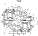
- the first shaft (55) of the first gate rotor (50) and the second shaft (65) of the second gate rotor (60) are substantially orthogonal to a phantom plane (F) extending along the drive shaft (25) of the screw rotor (40) (see FIG. 2 ).
- the first gates (51) of the first gate rotor (50) and the second gates (61) of the second gate rotor (60) are arranged on the same phantom plane (F).
- a case of moving a rotary tool (not shown) of a machine tool toward the casing (10) from the front to the back of the sheet of FIG. 2 will be described.
- a hole for the screw rotor (40) is formed in the casing (10) using the rotary tool, and then a retaining table (not shown) of the machine tool is rotated 90° toward the front while retaining the casing (10).
- the first shaft (55) of the first gate rotor (50) and the second shaft (65) of the second gate rotor (60) are oriented toward the front side of the sheet of FIG. 2 .
- the screw compressor (1) is provided with slide valves (27).
- Each of the slide valves (27) is housed in a corresponding one of valve storing portions (16) which are portions of the partition wall (15) protruding radially outward at two circumferential portions of the partition wall (15) (see FIG. 2 ).
- the slide valves (27) are slidable along the axis of the partition wall (15).
- the slide valves (27) face the outer peripheral surface of the screw rotor (40) when inserted in the corresponding valve storing portions (16).
- the screw compressor (1) is provided with a driving mechanism (28) configured to drive and slide the slide valves (27).
- the slide valves (27) are valves, the positions of which are adjustable in the axial direction of the screw rotor (40).
- the slide valves (27) can be used as an unloading mechanism configured to return the refrigerant that is being compressed in the first compression chamber (21) or the second compression chamber (22) toward the suction side to change the operating capacity.
- the slide valves (27) can also be used as a compression ratio regulation mechanism configured to adjust the timing when the refrigerant is discharged from the first compression chamber (21) or the second compression chamber (22) to regulate the compression ratio (internal volume ratio).
- the partition wall (15) is provided with fixed discharge ports (not shown) which always communicate with the first compression chamber (21) and the second compression chamber (22), regardless of the positions of the slide valves (27).
- the first compression chamber (21) is a compression chamber on a low-stage side in two-stage compression, and compresses the refrigerant introduced into the casing (10) at a suction pressure to an intermediate pressure higher than the suction pressure.
- the second compression chamber (22) is a compression chamber on a high-stage side in the two-stage compression, and compresses the refrigerant at the intermediate pressure to a discharge pressure higher than the intermediate pressure.
- the casing (10) includes therein the low-pressure space (S1) communicating with the suction side of the first compression chamber (21), the intermediate-pressure space (S2) communicating with the discharge side of the first compression chamber (21) and the suction side of the second compression chamber (22), and the high-pressure space (S3) communicating with the discharge side of the second compression chamber (22).
- a low-pressure pipe (6) through which a low-pressure refrigerant flows is connected to the first gate rotor chamber (17).
- the low-pressure refrigerant is supplied to the first gate rotor chamber (17) from the low-pressure pipe (6), and the first gate rotor chamber (17) thus serves as the low-pressure space (S 1).
- the first gate rotor chamber (17) is configured to supply the low-pressure refrigerant to the suction opening of the first compression chamber (21).
- the low-pressure refrigerant is compressed in the first compression chamber (21) to be an intermediate-pressure refrigerant.
- the intermediate-pressure refrigerant compressed in the first compression chamber (21) to the intermediate pressure is supplied to the second gate rotor chamber (18) through a space where the motor (not shown) is arranged.
- the intermediate-pressure refrigerant is supplied to the second gate rotor chamber (18), and the second gate rotor chamber (18) thus serves as the intermediate-pressure space (S2).
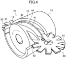
- An axial end portion of the partition wall (15) near the intermediate-pressure space (S2) has a cut-out (13) (see FIG. 4 as well).
- the cut-out (13) is formed by cutting out a portion of the partition wall (15).
- the intermediate-pressure space (S2) and the second compression chamber (22) communicate with each other through the cut-out (13).
- An oil film is formed between the first end portion (42) of the screw rotor (40) and the partition wall (15). The oil film reduces the circulation of the refrigerant between the partition wall (15) and the first compression chamber (21) of the screw rotor (40).
- the intermediate-pressure refrigerant flowing through the intermediate-pressure space (S2) is supplied through the cut-out (13) of the partition wall (15) to the suction opening of the second compression chamber (22).
- the intermediate-pressure refrigerant is compressed in the second compression chamber (22) to be a high-pressure refrigerant.
- the high-pressure refrigerant compressed in the second compression chamber (22) to the high pressure is supplied to the high-pressure space (S3).
- the high-pressure refrigerant flowing through the high-pressure space (S3) is discharged from a discharge port (not shown) of the casing (10).
- the low-pressure space (S1), the first compression chamber (21), the intermediate-pressure space (S2), the second compression chamber (22), and the high-pressure space (S3) are connected together in the order of the pressure of the fluid from low pressure to high pressure.
- the partition wall (15) includes the first envelope portion (11) and the second envelope portion (12).
- the first envelope portion (11) is configured to isolate the first compression chamber (21) from the low-pressure space (S1) on its outer peripheral side before the first compression chamber (21) reaches, during the rotation of the screw rotor (40), a suction shut-off position where the first compression chamber (21) is fully closed by the first gate rotor (50).
- An edge portion of the first envelope portion (11) is shaped to draw a curve parallel to the edge portion of a circumferential sealing surface (44) of the screw rotor (40).
- the edge portion of the first envelope portion (11) is shaped so that the entire length of the edge portion can overlap with the circumferential sealing surface (44) which moves along with the rotation of the screw rotor (40).
- the second envelope portion (12) is configured to isolate the second compression chamber (22) from the intermediate-pressure space (S2) on its outer peripheral side before the second compression chamber (22) reaches, during the rotation of the screw rotor (40), a suction shut-off position where the second compression chamber (22) is fully closed by the second gate rotor (60).
- An edge portion of the second envelope portion (12) is shaped to draw a curve parallel to the edge portion of the circumferential sealing surface (44) of the screw rotor (40).
- the edge portion of the second envelope portion (12) is shaped so that the entire length of the edge portion can overlap with the circumferential sealing surface (44) which moves along with the rotation of the screw rotor (40).
- the axial length (D1) of the first envelope portion (11) and the axial length (D2) of the second envelope portion (12) that extend along the drive shaft (25) of the screw rotor (40) are set to be different from each other. Specifically, the axial length (D1) of the first envelope portion (11) is greater than the axial length (D2) of the second envelope portion (12).
- the timing when the first compression chamber (21) is fully closed by the first gate rotor (50) is earlier than the timing when the second compression chamber (22) is fully closed by the second gate rotor (60).
- the volume of the first compression chamber (21) is greater than the volume of the second compression chamber (22).
- the axial length (D1) of the first envelope portion (11) and the axial length (D2) of the second envelope portion (12) are set such that the volume of the first compression chamber (21) is about two to three times the volume of the second compression chamber (22).
- the compression mechanism (20) continuously repeats a suction phase, a compression phase, and a discharge phase.
- the shaded first compression chamber (21) communicates with the space on the suction side.
- the helical groove (41) corresponding to the first compression chamber (21) meshes with the first gate (51) of the first gate rotor (50).
- the screw rotor (40) rotates, the first gate (51) relatively moves toward the terminal end of the helical groove (41), causing the volume of the first compression chamber (21) to increase. As a result, the refrigerant is sucked into the first compression chamber (21).
- the compression phase illustrated in FIG. 8 is performed.
- the shaded first compression chamber (21) is fully closed. That is, the helical groove (41) corresponding to the first compression chamber (21) is separated, by the first gate (51), from the space on the suction side.
- the first gate (51) approaches the terminal end of the helical groove (41) in accordance with the rotation of the screw rotor (40)
- the volume of the first compression chamber (21) gradually decreases. As a result, the refrigerant in the first compression chamber (21) is compressed.
- the discharge phase illustrated in FIG. 9 is performed.
- the shaded first compression chamber (21) communicates with the fixed discharge port via the end portion on the discharge side (right end portion in the figure).
- the first gate (51) approaches the terminal end of the helical groove (41) in accordance with the rotation of the screw rotor (40)
- the refrigerant that has been compressed is pushed out of the first compression chamber (21) through the fixed discharge port to the space on the discharge side.
- the suction phase, the compression phase, and the discharge phase in the high-stage second compression chamber (22) are similar to those in the low-stage first compression chamber (21), and thus will not be described.
- Focus is given to one of the helical grooves (41) forming the first compression chamber (21) in the suction phase as illustrated in FIG. 10 .
- a portion of the helical groove (41) is covered with the first envelope portion (11), and the remaining portion faces the low-pressure space (S1).
- the first gate (51) enters the helical groove (41) from the starting end of the helical groove (41).
- the first compression chamber (21) in the suction phase formed by the helical groove (41) communicates with the low-pressure space (S1) on the outer peripheral side of the screw rotor (40).
- the low-pressure refrigerant flows into the first compression chamber (21) from the outer peripheral side of the screw rotor (40).
- FIG. 11 is the state after further rotation of the screw rotor (40) from the state illustrated in FIG. 10 .
- the first gate (51) that has entered the helical groove (41) is in sliding contact with the groove wall and the groove bottom of the helical groove (41).
- the circumferential sealing surface (44) of the screw rotor (40) overlaps with the first envelope portion (11).
- the first compression chamber (21) turns into a closed space separated from the low-pressure space (S1) by both the first envelope portion (11) and the first gate (51), and the suction phase ends. This position is referred to as a "suction shut-off position.”
- the first compression chamber (21) in the suction phase moves from a position at which the helical groove (41) faces the low-pressure space (S1) to a position at which the helical groove (41) is covered with the first envelope portion (11), resulting in separation from the low-pressure space (S1).
- the first gate (51) separates the helical groove (41) from the low-pressure space (S1).
- the shape of the first envelope portion (11) is determined so that the refrigerant in the first compression chamber (21) flows out to the low-pressure space (S1) before the first envelope portion (11) reaches the suction shut-off position.
- the second compression chamber (22) also turns into a closed space separated from the intermediate-pressure space (S2) by both the second envelope portion (12) and the second gate (61), and the suction phase ends.
- the second compression chamber (22) in the suction phase moves from a position at which the helical groove (41) faces the intermediate-pressure space (S2) to a position at which the helical groove (41) is covered with the second envelope portion (12), resulting in separation from the intermediate-pressure space (S2).
- the second gate (61) separates the helical groove (41) from the intermediate-pressure space (S2).
- the shape of the second envelope portion (12) is determined so that the refrigerant in the second compression chamber (22) flows out to the intermediate-pressure space (S2) before the second envelope portion (12) reaches the suction shut-off position.
- the axial length (D1) of the first envelope portion (11) is greater than the axial length (D2) of the second envelope portion (12).
- the timing of full closure of the first compression chamber (21) is earlier than the timing of full closure of the second compression chamber (22).
- the axial length (D1) of the first envelope portion (11) is different from the axial length (D2) of the second envelope portion (12). It is thus possible to set the volume ratio between the first compression chamber (21) and the second compression chamber (22) appropriately by changing the timing of full closure of the first compression chamber (21) and the timing of full closure of the second compression chamber (22).
- the volume ratio between the first compression chamber (21) and the second compression chamber (22) appropriately in the screw compressor including the single screw rotor (40), the first gate rotor (50), and the second gate rotor (60).
- the first shaft (55) of the first gate rotor (50) and the second shaft (65) of the second gate rotor (60) are substantially orthogonal to the phantom plane (F) extending along the drive shaft (25) of the screw rotor (40). It is thus possible to form a hole for supporting the shaft of each of the screw rotor (40), the first gate rotor (50), and the second gate rotor (60) while relatively moving the rotary tool of the machine tool in one direction, without changing the posture of the casing (10) retained. The accuracy in machining the casing (10) can thus be ensured.
- a refrigeration apparatus includes the screw compressor (1) and the refrigerant circuit (2a) through which the refrigerant compressed by the screw compressor (1) flows. It is thus possible to provide the refrigeration apparatus (2) including the screw compressor (1).
- the axial length (D2) of the second envelope portion (12) is set to be equal to the axial length (D1) of the first envelope portion (11) (see FIG. 5 ).
- the second envelope portion (12) has an opening (35) passing through the second envelope portion (12) from the inner surface to the outer surface of the second envelope portion (12).
- the opening (35) is a through hole (36) formed in the second envelope portion (12).
- the through hole (36) is formed at a position in an edge portion of the second envelope portion (12) near the second gate rotor (60).
- the refrigerant flows out to the intermediate-pressure space (S2) from the through hole (36) even when the second compression chamber (22) in the suction phase moves from a position at which the helical groove (41) faces the intermediate-pressure space (S2) to a position at which the helical groove (41) is covered with the edge portion of the second envelope portion (12).
- the screw rotor (40) further rotates thereafter, and the sealing surface (44) of the helical groove (41) is covered with the second envelope portion (12) at a position behind the through hole (36) (upper position in FIG. 12 ), the second compression chamber (22) is fully closed.
- the through hole (36) formed in the second envelope portion (12) as described above makes the second compression chamber (22) fully closed by the second gate rotor (60) at later timing than when the first compression chamber (21) is fully closed by the first gate rotor (50). As a result, the volume of the first compression chamber (21) is greater than the volume of the second compression chamber (22). It is preferable that the position of the through hole (36) in the second envelope portion (12) is set such that the volume of the first compression chamber (21) is about two to three times the volume of the second compression chamber (22).
- the second envelope portion (12) has the opening (35). It is thus possible to set the volume ratio between the first compression chamber (21) and the second compression chamber (22) appropriately by changing the timing of full closure of the first compression chamber (21) and the timing of full closure of the second compression chamber (22).
- the opening (35) is a through hole (36) formed in the second envelope portion (12).
- the through hole (36) formed in the second envelope portion (12) makes it possible to set the volume ratio between the first compression chamber (21) and the second compression chamber (22) appropriately.
- the axial length (D2) of the second envelope portion (12) is set to be equal to the axial length (D1) of the first envelope portion (11) (see FIG. 5 ).
- the second envelope portion (12) has an opening (35) passing through the second envelope portion (12) from the inner surface to the outer surface of the second envelope portion (12).
- the opening (35) is a cut-out (37) formed in an edge portion of the second envelope portion (12).
- the cut-out (37) is formed at a position in the edge portion of the second envelope portion (12) near the second gate rotor (60) and extends in a circumferential direction.
- the refrigerant flows out to the intermediate-pressure space (S2) from the cut-out (37) even when the second compression chamber (22) in the suction phase moves from a position at which the helical groove (41) faces the intermediate-pressure space (S2) to a position at which the helical groove (41) is covered with the second envelope portion (12).
- the screw rotor (40) further rotates thereafter, and the helical groove (41) is covered with the second envelope portion (12) at a position behind the cut-out (37) (upper position in FIG. 13 ), the second compression chamber (22) is fully closed.
- the cut-out (37) formed in the second envelope portion (12) as described above makes the second compression chamber (22) fully closed by the second gate rotor (60) at later timing than when the first compression chamber (21) is fully closed by the first gate rotor (50). As a result, the volume of the first compression chamber (21) is greater than the volume of the second compression chamber (22). It is preferable that the position of the cut-out (37) in the second envelope portion (12) is set such that the volume of the first compression chamber (21) is about two to three times the volume of the second compression chamber (22).
- the opening (35) is the cut-out (37) formed in the edge portion of the second envelope portion (12).
- the cut-out (37) formed at the edge portion of the second envelope portion (12) makes it possible to set the volume ratio between the first compression chamber (21) and the second compression chamber (22) appropriately.
- a screw compressor (1) includes a casing (10) and a compression mechanism (20).
- the casing (10) houses the compression mechanism (20).
- the compression mechanism (20) is coupled to a motor (26) via a drive shaft (25).
- the compression mechanism (20) has a partition wall (15) provided in the casing (10), one screw rotor (40), a first rotor (31), and a second rotor (32).
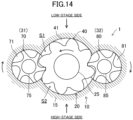
- the first rotor (31) is configured as a first female rotor (70) having a plurality of first helical grooves (71).
- the second rotor (32) is configured as a second female rotor (80) having a plurality of second helical grooves (81).
- the screw rotor (40) is configured as one male rotor that meshes with the first female rotor (70) and the second female rotor (80).
- the screw compressor (1) of this embodiment is a so-called tri-rotor compressor.
- the screw rotor (40), the first female rotor (70), and the second female rotor (80) are fitted into the partition wall (15).
- the partition wall (15) covers the outer peripheral surfaces of the screw rotor (40), the first female rotor (70), and the second female rotor (80).
- the first female rotor (70) and the second female rotor (80) mesh with the screw rotor (40).
- the drive shaft (25) of the screw rotor (40) is rotatably supported via a bearing (73).
- the first female rotor (70) has a first shaft (75) rotatably supported via another bearing (73).
- the second female rotor (80) has a second shaft (85) rotatably supported via still another bearing (73).
- the partition wall (15) includes a first envelope portion (11) and a second envelope portion (12).
- a space surrounded by the inner peripheral surface of the first envelope portion (11), the helical grooves (41) of the screw rotor (40), the walls of the first helical grooves (71) of the first female rotor (70), and the walls of the second helical grooves (81) of the second female rotor (80) is a first compression chamber (21).
- a space surrounded by the inner peripheral surface of the second envelope portion (12), the helical grooves (41) of the screw rotor (40), the walls of the first helical grooves (71) of the first female rotor (70), and the walls of the second helical grooves (81) of the second female rotor (80) is a second compression chamber (22).
- the first compression chamber (21) is a compression chamber on a low-stage side in two-stage compression, and compresses the refrigerant introduced into the casing (10) at a suction pressure to an intermediate pressure higher than the suction pressure.
- the second compression chamber (22) is a compression chamber on a high-stage side in the two-stage compression, and compresses the refrigerant at the intermediate pressure to a discharge pressure higher than the intermediate pressure.
- the casing (10) includes therein the low-pressure space (S1) communicating with the suction side of the first compression chamber (21), the intermediate-pressure space (S2) communicating with the discharge side of the first compression chamber (21) and the suction side of the second compression chamber (22), and the high-pressure space (S3) communicating with the discharge side of the second compression chamber (22).
- the low-pressure space (S1), the first compression chamber (21), the intermediate-pressure space (S2), the second compression chamber (22), and the high-pressure space (S3) are connected together in the order of the pressure of the fluid from low pressure to high pressure.
- the first envelope portion (11) is configured to isolate the first compression chamber (21) from the low-pressure space (S1) on its outer peripheral side before the first compression chamber (21) reaches, during the rotation of the screw rotor (40), a suction shut-off position where the first compression chamber (21) is fully closed by the first female rotor (70) and the second female rotor (80).
- An edge portion of the first envelope portion (11) is shaped to draw a curve parallel to the edge portion of a circumferential sealing surface (44) of the screw rotor (40).
- the edge portion of the first envelope portion (11) is shaped so that the entire length of the edge portion can overlap with the circumferential sealing surface (44) which moves along with the rotation of the screw rotor (40).
- the second envelope portion (12) is configured to isolate the second compression chamber (22) from the intermediate-pressure space (S2) on its outer peripheral side before the second compression chamber (22) reaches, during the rotation of the screw rotor (40), a suction shut-off position where the second compression chamber (22) is fully closed by the first female rotor (70) and the second female rotor (80).
- An edge portion of the second envelope portion (12) is shaped to draw a curve parallel to the edge portion of the circumferential sealing surface (44) of the screw rotor (40).
- the edge portion of the second envelope portion (12) is shaped so that the entire length of the edge portion can overlap with the circumferential sealing surface (44) which moves along with the rotation of the screw rotor (40).
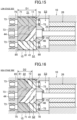
- the axial length (D1) of the first envelope portion (11) and the axial length (D2) of the second envelope portion (12) that extend along the drive shaft (25) of the screw rotor (40) are set to be different from each other. Specifically, the axial length (D1) of the first envelope portion (11) is greater than the axial length (D2) of the second envelope portion (12).
- the timing when the first compression chamber (21) is fully closed by the first female rotor (70) and the second female rotor (80) is earlier than the timing when the second compression chamber (22) is fully closed by the first female rotor (70) and the second female rotor (80).
- the volume of the first compression chamber (21) is greater than the volume of the second compression chamber (22).
- the axial length (D1) of the first envelope portion (11) and the axial length (D2) of the second envelope portion (12) are set such that the volume of the first compression chamber (21) is about two to three times the volume of the second compression chamber (22).
- the volume ratio between the first compression chamber (21) and the second compression chamber (22) appropriately in the screw compressor (1) including the single screw rotor (40) (male rotor), the first female rotor (70), and the second female rotor (80).
- the configuration and shape of the first gate rotor (50) and the ratio between the number of grooves of the screw rotor (40) and the number of teeth of the first gate rotor (50) described in the above embodiments are not limited thereto, and may be changed.
- fully closed timing in the tri-rotor screw compressor (1) is changed by setting the axial length (D1) of the first envelope portion (11) and the axial length (D2) of the second envelope portion (12) to be different from each other, but not limited thereto.
- the axial length (D1) of the first envelope portion (11) and the axial length (D2) of the second envelope portion (12) may be set to be equal to each other, and the second envelope portion (12) may have a through hole (36) (see FIG. 12 ) or a cut-out (37) (see FIG. 13 ) as the opening (35), thereby changing the fully closed timing.
- the present disclosure is useful for a screw compressor and a refrigeration apparatus.
Landscapes
- Engineering & Computer Science (AREA)
- Mechanical Engineering (AREA)
- General Engineering & Computer Science (AREA)
- Physics & Mathematics (AREA)
- Thermal Sciences (AREA)
- Applications Or Details Of Rotary Compressors (AREA)
Abstract
Description
- The present disclosure relates to a screw compressor and a refrigeration apparatus.
-
Patent Document 1 discloses a screw compressor having a first compression chamber where a fluid with a suction pressure is compressed to an intermediate pressure, and a second compression chamber where the fluid with the intermediate pressure is compressed to a discharge pressure. The first compression chamber and the second compression chamber are formed between a single screw rotor and a plurality of gates. - Patent Document 1:
Japanese Unexamined Patent Publication No. 2021-162021 - Here, in a screw compressor that can perform two-stage compression, it is necessary to set the volume ratio between a first compression chamber on the low-stage side and a second compression chamber on the high-stage side appropriately in order to efficiently compress, in the second compression chamber, the refrigerant compressed in the first compression chamber.
- It is an object of the present disclosure to provide a screw compressor in which the ratio between volumes of a low-stage compression chamber and a high-stage compression chamber is appropriately set.
- A first aspect of the present disclosure is directed to a screw compressor including: a screw rotor (40) having a plurality of helical grooves (41); a first rotor (31) configured to mesh with the helical grooves (41) of the screw rotor (40); a second rotor (32) configured to mesh with the helical grooves (41) of the screw rotor (40); and a casing (10) having a partition wall (15), the partition wall (15) rotatably retaining the screw rotor (40) and covering an outer peripheral surface of the screw rotor (40), wherein the partition wall (15) includes a first envelope portion (11) to form a first compression chamber (21), and a second envelope portion (12) to form a second compression chamber (22), the first compression chamber (21) is formed inside the first envelope portion (11) by the screw rotor (40) and the first rotor (31), the first compression chamber (21) compressing a fluid introduced into the casing (10) with a suction pressure to an intermediate pressure higher than the suction pressure, the second compression chamber (22) is formed inside the second envelope portion (12) by the screw rotor (40) and the second rotor (32), the second compression chamber (22) compressing the fluid with the intermediate pressure to a discharge pressure higher than the intermediate pressure, and an axial length (D1) of the first envelope portion (11) and an axial length (D2) of the second envelope portion (12) that extend along a drive shaft (25) of the screw rotor (40) are different from each other.
- According to the first aspect, the axial length (D1) of the first envelope portion (11) is different from the axial length (D2) of the second envelope portion (12). It is thus possible to set the volume ratio between the first compression chamber (21) and the second compression chamber (22) appropriately by changing the timing of full closure of the first compression chamber (21) and the timing of full closure of the second compression chamber (22).
- A second aspect of the present disclosure is directed to a screw compressor including: a screw rotor (40) having a plurality of helical grooves (41); a first rotor (31) configured to mesh with the helical grooves (41) of the screw rotor (40); a second rotor (32) configured to mesh with the helical grooves (41) of the screw rotor (40); and a casing (10) having a partition wall (15), the partition wall (15) rotatably retaining the screw rotor (40) and covering an outer peripheral surface of the screw rotor (40), wherein the partition wall (15) includes a first envelope portion (11) to form a first compression chamber (21), and a second envelope portion (12) to form a second compression chamber (22), the first compression chamber (21) is formed inside the first envelope portion (11) by the screw rotor (40) and the first rotor (31), the first compression chamber (21) compressing a fluid introduced into the casing (10) with a suction pressure to an intermediate pressure higher than the suction pressure, the second compression chamber (22) is formed inside the second envelope portion (12) by the screw rotor (40) and the second rotor (32), the second compression chamber (22) compressing the fluid with the intermediate pressure to a discharge pressure higher than the intermediate pressure, and the second envelope portion (12) has an opening (35) passing through the second envelope portion (12) from an inner surface to an outer surface of the second envelope portion (12).
- According to the second aspect, the second envelope portion (12) has the opening (35). It is thus possible to set the volume ratio between the first compression chamber (21) and the second compression chamber (22) appropriately by changing the timing of full closure of the first compression chamber (21) and the timing of full closure of the second compression chamber (22).
- A third aspect of the present disclosure is the screw compressor of the second aspect. In the third aspect, the opening (35) is a through hole (36) formed in the second envelope portion (12).
- According to the third aspect, the through hole (36) formed in the second envelope portion (12) makes it possible to set the volume ratio between the first compression chamber (21) and the second compression chamber (22) appropriately.
- A fourth aspect of the present disclosure is the screw compressor of the second aspect. In the fourth aspect, the opening (35) is a cut-out (37) formed in an edge portion of the second envelope portion (12).
- According to the fourth aspect, the cut-out (37) formed at the edge portion of the second envelope portion (12) makes it possible to set the volume ratio between the first compression chamber (21) and the second compression chamber (22) appropriately.
- A fifth aspect of the present disclosure is the screw compressor of any one of the first to fourth aspects. In the fifth aspect, the first rotor (31) is configured as a first gate rotor (50) including a plurality of first gates (51) arranged radially, the second rotor (32) is configured as a second gate rotor (60) including a plurality of second gates (61) arranged radially, and the first gates (51) and the second gates (61) mesh with the helical grooves (41) of the single screw rotor (40).
- According to the fifth aspect, it is possible to set the volume ratio between the first compression chamber (21) and the second compression chamber (22) appropriately in the screw compressor including the single screw rotor (40), the first gate rotor (50), and the second gate rotor (60).
- A sixth aspect of the present disclosure is the screw compressor of the fifth aspect. In the sixth aspect, a first shaft (55) of the first gate rotor (50) and a second shaft (65) of the second gate rotor (60) are substantially orthogonal to a phantom plane (F) extending along the drive shaft (25) of the screw rotor (40).
- According to the sixth aspect, it is possible to form a hole for supporting the shaft of each of the screw rotor (40), the first gate rotor (50), and the second gate rotor (60) while relatively moving the rotary tool of the machine tool in one direction, without changing the posture of the casing (10) retained. The accuracy in machining the casing (10) can thus be ensured.
- A seventh aspect of the present disclosure is the screw compressor of any one of the first to fourth aspects. In the seventh aspect, the first rotor (31) is configured as a first female rotor (70) having a plurality of first helical grooves (71), the second rotor (32) is configured as a second female rotor (80) having a plurality of second helical grooves (81), and the screw rotor (40) is configured as one male rotor that meshes with the first female rotor (70) and the second female rotor (80).
- According to the seventh aspect, it is possible to set the volume ratio between the first compression chamber (21) and the second compression chamber (22) appropriately in the screw compressor including the single male rotor, the first female rotor (70), and the second female rotor (80).
- An eighth aspect of the present disclosure is directed to a refrigeration apparatus including: the screw compressor (1) of any one of the first to seventh aspects; and a refrigerant circuit (2a) through which a refrigerant compressed by the screw compressor (1) flows.
- According to the eighth aspect, it is possible to provide the refrigeration apparatus including the screw compressor (1).
-
-
FIG. 1 is a refrigerant circuit diagram illustrating a configuration of a refrigeration apparatus according to a first embodiment. -
FIG. 2 is a cross-sectional view of a configuration of a screw compressor as viewed from the back side. -
FIG. 3 is a sectional side view of the configuration of the screw compressor. -
FIG. 4 is a perspective view illustrating a configuration of a compression mechanism. -
FIG. 5 is a plan view illustrating a configuration of a first envelope portion. -
FIG. 6 is a plan view illustrating a configuration of a second envelope portion. -
FIG. 7 is a plan view illustrating a suction phase of the screw compressor. -
FIG. 8 is a plan view illustrating a compression phase of the screw compressor. -
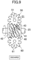
FIG. 9 is a plan view illustrating a discharge phase of the screw compressor. -
FIG. 10 is a developed view of a screw rotor and a partition wall, illustrating the state before the first compression chamber and the second compression chamber are fully closed. -
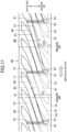
FIG. 11 is a developed view of the screw rotor and the partition wall, illustrating the state in which the first compression chamber and the second compression chamber are fully closed. -
FIG. 12 is a plan view illustrating a configuration of a second envelope portion in a screw compressor according to a second embodiment. -
FIG. 13 is a plan view illustrating a configuration of a second envelope portion in a screw compressor according to a third embodiment. -
FIG. 14 is a cross-sectional view illustrating a configuration of a screw compressor according to a fourth embodiment. -
FIG. 15 is a plan view illustrating a configuration of a first envelope portion. -
FIG. 16 is a plan view illustrating a configuration of a second envelope portion. - As illustrated in
FIG. 1 , a screw compressor (1) is provided in a refrigeration apparatus (2). The refrigeration apparatus (2) includes a refrigerant circuit (2a) filled with a refrigerant. The refrigerant circuit (2a) has a screw compressor (1), a radiator (3), a decompression mechanism (4), and an evaporator (5). The decompression mechanism (4) is, for example, an expansion valve. The refrigerant circuit (2a) performs a vapor compression refrigeration cycle. - The refrigeration apparatus (2) is an air conditioner. The air conditioner may be a cooling-only apparatus, a heating-only apparatus, or an air conditioner switchable between cooling and heating. In this case, the air conditioner has a switching mechanism (e.g., a four-way switching valve) configured to switch the direction of circulation of the refrigerant. The refrigeration apparatus (2) may be a water heater, a chiller unit, or a cooling apparatus configured to cool air in an internal space. The cooling apparatus cools the air in a refrigerator, a freezer, or a container, for example.
- As illustrated in
FIGS. 2 and3 , the screw compressor (1) includes a casing (10) and a compression mechanism (20). The casing (10) houses the compression mechanism (20). The compression mechanism (20) is coupled to a motor (not shown) via a drive shaft (25). - The casing (10) includes therein a low-pressure space (S1) into which a low-pressure refrigerant flows, an intermediate-pressure space (S2) into which an intermediate-pressure refrigerant with a pressure higher than that of the low-pressure refrigerant flows, and a high-pressure space (S3) into which a high-pressure refrigerant with a pressure higher than that of the intermediate-pressure refrigerant flows.
- The compression mechanism (20) has a partition wall (15) provided in the casing (10), one screw rotor (40), a first rotor (31), and a second rotor (32).
- The partition wall (15) is cylindrical. The screw rotor (40) is fitted into the partition wall (15). The partition wall (15) covers the outer peripheral surface of the screw rotor (40). The first rotor (31) and the second rotor (32) pass through the partition wall (15) to mesh with the screw rotor (40).
- The screw rotor (40) is a metal member having a generally columnar shape. The outer diameter of the screw rotor (40) is set to be slightly smaller than the inner diameter of the partition wall (15). The outer peripheral surface of the screw rotor (40) is close to the inner peripheral surface of the partition wall (15).
- An outer periphery of the screw rotor (40) has a plurality of helical grooves (41) extending helically. The helical grooves (41) extend from one axial end toward the other axial end of the screw rotor (40). A first end portion (42) and a second end portion (43) are provided at respective ends of the screw rotor (40) in the axial direction. Each of the first end portion (42) and the second end portion has a smooth cylindrical outer peripheral surface without any helical grooves (41). The helical grooves (41) of the screw rotor (40) are formed between the first end portion (42) and the second end portion (43) of the screw rotor (40). The drive shaft (25) is coupled to the screw rotor (40). The drive shaft (25) and the screw rotor (40) rotate together.
- As illustrated in
FIG. 2 , the first rotor (31) is configured as a first gate rotor (50). The first gate rotor (50) has first gates (51), which are a plurality of teeth arranged radially. The first gates (51) mesh with the helical grooves (41) of the screw rotor (40). The first gate rotor (50) is housed in a first gate rotor chamber (17). The first gate rotor chamber (17) is defined in the casing (10), and is adjacent to the partition wall (15). - The second rotor (32) is configured as a second gate rotor (60). The second gate rotor (60) has second gates (61), which are a plurality of teeth arranged radially. The second gates (61) mesh with the helical grooves (41) of the screw rotor (40). The second gate rotor (60) is housed in a second gate rotor chamber (18). The second gate rotor chamber (18) is defined in the casing (10), and is adjacent to the partition wall (15).
- In the compression mechanism (20), a space surrounded by the inner peripheral surface of a first envelope portion (11) of the partition wall (15), which will be described later, the helical grooves (41) of the screw rotor (40), and the first gates (51) of the first gate rotor (50) is a first compression chamber (21).
- In the compression mechanism (20), a space surrounded by the inner peripheral surface of a second envelope portion (12) of the partition wall (15), which will be described later, the helical grooves (41) of the screw rotor (40), and the second gates (61) of the second gate rotor (60) is a second compression chamber (22).
- A bearing housing (52) is provided in the first gate rotor chamber (17). The bearing housing (52) includes a ball bearing (53). A first shaft (55) of the first gate rotor (50) is rotatably supported via the ball bearing (53).
- Another bearing housing (52) is provided in the second gate rotor chamber (18). The bearing housing (52) includes a ball bearing (53). A second shaft (65) of the second gate rotor (60) is rotatably supported via the ball bearing (53).
- The first shaft (55) of the first gate rotor (50) and the second shaft (65) of the second gate rotor (60) are substantially orthogonal to a phantom plane (F) extending along the drive shaft (25) of the screw rotor (40) (see
FIG. 2 ). Specifically, the first gates (51) of the first gate rotor (50) and the second gates (61) of the second gate rotor (60) are arranged on the same phantom plane (F). - Thus, in machining the casing (10) using a machine tool (not shown), a setup change process is not needed, in which the casing (10) retained by the machine tool is removed temporarily for adjustment of the retaining posture, resulting in an improvement in the working efficiency.
- Specifically, a case of moving a rotary tool (not shown) of a machine tool toward the casing (10) from the front to the back of the sheet of
FIG. 2 will be described. In this case, a hole for the screw rotor (40) is formed in the casing (10) using the rotary tool, and then a retaining table (not shown) of the machine tool is rotated 90° toward the front while retaining the casing (10). Accordingly, the first shaft (55) of the first gate rotor (50) and the second shaft (65) of the second gate rotor (60) are oriented toward the front side of the sheet ofFIG. 2 . It is thus possible to form a hole for each of the first gate rotor (50) and the second gate rotor (60) by simply moving the rotary tool from the front to the back of the sheet ofFIG. 2 , without changing the posture of the casing (10) retained. As a result, the accuracy in machining the casing (10) can be ensured. - As illustrated in
FIG. 3 , the screw compressor (1) is provided with slide valves (27). Each of the slide valves (27) is housed in a corresponding one of valve storing portions (16) which are portions of the partition wall (15) protruding radially outward at two circumferential portions of the partition wall (15) (seeFIG. 2 ). - The slide valves (27) are slidable along the axis of the partition wall (15). The slide valves (27) face the outer peripheral surface of the screw rotor (40) when inserted in the corresponding valve storing portions (16). The screw compressor (1) is provided with a driving mechanism (28) configured to drive and slide the slide valves (27).
- The slide valves (27) are valves, the positions of which are adjustable in the axial direction of the screw rotor (40). The slide valves (27) can be used as an unloading mechanism configured to return the refrigerant that is being compressed in the first compression chamber (21) or the second compression chamber (22) toward the suction side to change the operating capacity. The slide valves (27) can also be used as a compression ratio regulation mechanism configured to adjust the timing when the refrigerant is discharged from the first compression chamber (21) or the second compression chamber (22) to regulate the compression ratio (internal volume ratio).
- The partition wall (15) is provided with fixed discharge ports (not shown) which always communicate with the first compression chamber (21) and the second compression chamber (22), regardless of the positions of the slide valves (27).
- The first compression chamber (21) is a compression chamber on a low-stage side in two-stage compression, and compresses the refrigerant introduced into the casing (10) at a suction pressure to an intermediate pressure higher than the suction pressure. The second compression chamber (22) is a compression chamber on a high-stage side in the two-stage compression, and compresses the refrigerant at the intermediate pressure to a discharge pressure higher than the intermediate pressure.
- The casing (10) includes therein the low-pressure space (S1) communicating with the suction side of the first compression chamber (21), the intermediate-pressure space (S2) communicating with the discharge side of the first compression chamber (21) and the suction side of the second compression chamber (22), and the high-pressure space (S3) communicating with the discharge side of the second compression chamber (22).
- Specifically, a low-pressure pipe (6) through which a low-pressure refrigerant flows is connected to the first gate rotor chamber (17). The low-pressure refrigerant is supplied to the first gate rotor chamber (17) from the low-pressure pipe (6), and the first gate rotor chamber (17) thus serves as the low-pressure space (S 1). The first gate rotor chamber (17) is configured to supply the low-pressure refrigerant to the suction opening of the first compression chamber (21). The low-pressure refrigerant is compressed in the first compression chamber (21) to be an intermediate-pressure refrigerant.
- The intermediate-pressure refrigerant compressed in the first compression chamber (21) to the intermediate pressure is supplied to the second gate rotor chamber (18) through a space where the motor (not shown) is arranged. The intermediate-pressure refrigerant is supplied to the second gate rotor chamber (18), and the second gate rotor chamber (18) thus serves as the intermediate-pressure space (S2).
- An axial end portion of the partition wall (15) near the intermediate-pressure space (S2) has a cut-out (13) (see
FIG. 4 as well). The cut-out (13) is formed by cutting out a portion of the partition wall (15). The intermediate-pressure space (S2) and the second compression chamber (22) communicate with each other through the cut-out (13). An oil film is formed between the first end portion (42) of the screw rotor (40) and the partition wall (15). The oil film reduces the circulation of the refrigerant between the partition wall (15) and the first compression chamber (21) of the screw rotor (40). - The intermediate-pressure refrigerant flowing through the intermediate-pressure space (S2) is supplied through the cut-out (13) of the partition wall (15) to the suction opening of the second compression chamber (22). The intermediate-pressure refrigerant is compressed in the second compression chamber (22) to be a high-pressure refrigerant.
- The high-pressure refrigerant compressed in the second compression chamber (22) to the high pressure is supplied to the high-pressure space (S3). The high-pressure refrigerant flowing through the high-pressure space (S3) is discharged from a discharge port (not shown) of the casing (10).
- As described above, the low-pressure space (S1), the first compression chamber (21), the intermediate-pressure space (S2), the second compression chamber (22), and the high-pressure space (S3) are connected together in the order of the pressure of the fluid from low pressure to high pressure.
- As illustrated in
FIGS. 5 and 6 , the partition wall (15) includes the first envelope portion (11) and the second envelope portion (12). The first envelope portion (11) is configured to isolate the first compression chamber (21) from the low-pressure space (S1) on its outer peripheral side before the first compression chamber (21) reaches, during the rotation of the screw rotor (40), a suction shut-off position where the first compression chamber (21) is fully closed by the first gate rotor (50). - An edge portion of the first envelope portion (11) is shaped to draw a curve parallel to the edge portion of a circumferential sealing surface (44) of the screw rotor (40). In other words, the edge portion of the first envelope portion (11) is shaped so that the entire length of the edge portion can overlap with the circumferential sealing surface (44) which moves along with the rotation of the screw rotor (40).
- The second envelope portion (12) is configured to isolate the second compression chamber (22) from the intermediate-pressure space (S2) on its outer peripheral side before the second compression chamber (22) reaches, during the rotation of the screw rotor (40), a suction shut-off position where the second compression chamber (22) is fully closed by the second gate rotor (60).
- An edge portion of the second envelope portion (12) is shaped to draw a curve parallel to the edge portion of the circumferential sealing surface (44) of the screw rotor (40). In other words, the edge portion of the second envelope portion (12) is shaped so that the entire length of the edge portion can overlap with the circumferential sealing surface (44) which moves along with the rotation of the screw rotor (40).
- In this embodiment, the axial length (D1) of the first envelope portion (11) and the axial length (D2) of the second envelope portion (12) that extend along the drive shaft (25) of the screw rotor (40) are set to be different from each other. Specifically, the axial length (D1) of the first envelope portion (11) is greater than the axial length (D2) of the second envelope portion (12).
- Thus, the timing when the first compression chamber (21) is fully closed by the first gate rotor (50) is earlier than the timing when the second compression chamber (22) is fully closed by the second gate rotor (60). As a result, the volume of the first compression chamber (21) is greater than the volume of the second compression chamber (22). It is preferable that the axial length (D1) of the first envelope portion (11) and the axial length (D2) of the second envelope portion (12) are set such that the volume of the first compression chamber (21) is about two to three times the volume of the second compression chamber (22).
- As can be seen, it is possible to set the volume ratio between the first compression chamber (21) and the second compression chamber (22) appropriately by changing the timing of full closure of the first compression chamber (21) and the timing of full closure of the second compression chamber (22).
- When the screw rotor (40) rotates, the first gate rotor (50) and the second gate rotor (60) meshing with the helical grooves (41) rotate. Thus, the compression mechanism (20) continuously repeats a suction phase, a compression phase, and a discharge phase.
- In the suction phase illustrated in
FIG. 7 , the shaded first compression chamber (21) communicates with the space on the suction side. The helical groove (41) corresponding to the first compression chamber (21) meshes with the first gate (51) of the first gate rotor (50). When the screw rotor (40) rotates, the first gate (51) relatively moves toward the terminal end of the helical groove (41), causing the volume of the first compression chamber (21) to increase. As a result, the refrigerant is sucked into the first compression chamber (21). - When the screw rotor (40) further rotates, the compression phase illustrated in
FIG. 8 is performed. In the compression phase, the shaded first compression chamber (21) is fully closed. That is, the helical groove (41) corresponding to the first compression chamber (21) is separated, by the first gate (51), from the space on the suction side. As the first gate (51) approaches the terminal end of the helical groove (41) in accordance with the rotation of the screw rotor (40), the volume of the first compression chamber (21) gradually decreases. As a result, the refrigerant in the first compression chamber (21) is compressed. - When the screw rotor (40) further rotates, the discharge phase illustrated in
FIG. 9 is performed. In the discharge phase, the shaded first compression chamber (21) communicates with the fixed discharge port via the end portion on the discharge side (right end portion in the figure). When the first gate (51) approaches the terminal end of the helical groove (41) in accordance with the rotation of the screw rotor (40), the refrigerant that has been compressed is pushed out of the first compression chamber (21) through the fixed discharge port to the space on the discharge side. - The suction phase, the compression phase, and the discharge phase in the high-stage second compression chamber (22) are similar to those in the low-stage first compression chamber (21), and thus will not be described.
- The difference between the timing of full closure of the first compression chamber (21) and the timing of full closure of the second compression chamber (22) will now be described.
- Focus is given to one of the helical grooves (41) forming the first compression chamber (21) in the suction phase as illustrated in
FIG. 10 . A portion of the helical groove (41) is covered with the first envelope portion (11), and the remaining portion faces the low-pressure space (S1). The first gate (51) enters the helical groove (41) from the starting end of the helical groove (41). In the state illustrated inFIG. 10 , the first compression chamber (21) in the suction phase formed by the helical groove (41) communicates with the low-pressure space (S1) on the outer peripheral side of the screw rotor (40). In this state, the low-pressure refrigerant flows into the first compression chamber (21) from the outer peripheral side of the screw rotor (40). -
FIG. 11 is the state after further rotation of the screw rotor (40) from the state illustrated inFIG. 10 . In the state illustrated inFIG. 11 , the first gate (51) that has entered the helical groove (41) is in sliding contact with the groove wall and the groove bottom of the helical groove (41). The circumferential sealing surface (44) of the screw rotor (40) overlaps with the first envelope portion (11). - Thus, the first compression chamber (21) turns into a closed space separated from the low-pressure space (S1) by both the first envelope portion (11) and the first gate (51), and the suction phase ends. This position is referred to as a "suction shut-off position."
- As can be seen, the first compression chamber (21) in the suction phase moves from a position at which the helical groove (41) faces the low-pressure space (S1) to a position at which the helical groove (41) is covered with the first envelope portion (11), resulting in separation from the low-pressure space (S1). At the same time, the first gate (51) separates the helical groove (41) from the low-pressure space (S1). In the screw compressor (1), the shape of the first envelope portion (11) is determined so that the refrigerant in the first compression chamber (21) flows out to the low-pressure space (S1) before the first envelope portion (11) reaches the suction shut-off position.
- Similarly, in the state illustrated in
FIG. 11 , the second compression chamber (22) also turns into a closed space separated from the intermediate-pressure space (S2) by both the second envelope portion (12) and the second gate (61), and the suction phase ends. - As can be seen, the second compression chamber (22) in the suction phase moves from a position at which the helical groove (41) faces the intermediate-pressure space (S2) to a position at which the helical groove (41) is covered with the second envelope portion (12), resulting in separation from the intermediate-pressure space (S2). At the same time, the second gate (61) separates the helical groove (41) from the intermediate-pressure space (S2). In the screw compressor (1), the shape of the second envelope portion (12) is determined so that the refrigerant in the second compression chamber (22) flows out to the intermediate-pressure space (S2) before the second envelope portion (12) reaches the suction shut-off position.
- Here, the axial length (D1) of the first envelope portion (11) is greater than the axial length (D2) of the second envelope portion (12). Thus, the timing of full closure of the first compression chamber (21) is earlier than the timing of full closure of the second compression chamber (22).
- According to a feature of this embodiment, the axial length (D1) of the first envelope portion (11) is different from the axial length (D2) of the second envelope portion (12). It is thus possible to set the volume ratio between the first compression chamber (21) and the second compression chamber (22) appropriately by changing the timing of full closure of the first compression chamber (21) and the timing of full closure of the second compression chamber (22).
- According to a feature of this embodiment, it is possible to set the volume ratio between the first compression chamber (21) and the second compression chamber (22) appropriately in the screw compressor including the single screw rotor (40), the first gate rotor (50), and the second gate rotor (60).
- According to a feature of this embodiment, the first shaft (55) of the first gate rotor (50) and the second shaft (65) of the second gate rotor (60) are substantially orthogonal to the phantom plane (F) extending along the drive shaft (25) of the screw rotor (40). It is thus possible to form a hole for supporting the shaft of each of the screw rotor (40), the first gate rotor (50), and the second gate rotor (60) while relatively moving the rotary tool of the machine tool in one direction, without changing the posture of the casing (10) retained. The accuracy in machining the casing (10) can thus be ensured.
- According to a feature of this embodiment, a refrigeration apparatus includes the screw compressor (1) and the refrigerant circuit (2a) through which the refrigerant compressed by the screw compressor (1) flows. It is thus possible to provide the refrigeration apparatus (2) including the screw compressor (1).
- In the following description, the same reference characters designate the same components as those of the first embodiment, and the description will be focused only on the differences.
- In the example illustrated in
FIG. 12 , the axial length (D2) of the second envelope portion (12) is set to be equal to the axial length (D1) of the first envelope portion (11) (seeFIG. 5 ). - The second envelope portion (12) has an opening (35) passing through the second envelope portion (12) from the inner surface to the outer surface of the second envelope portion (12). The opening (35) is a through hole (36) formed in the second envelope portion (12). The through hole (36) is formed at a position in an edge portion of the second envelope portion (12) near the second gate rotor (60).
- Here, the refrigerant flows out to the intermediate-pressure space (S2) from the through hole (36) even when the second compression chamber (22) in the suction phase moves from a position at which the helical groove (41) faces the intermediate-pressure space (S2) to a position at which the helical groove (41) is covered with the edge portion of the second envelope portion (12). When the screw rotor (40) further rotates thereafter, and the sealing surface (44) of the helical groove (41) is covered with the second envelope portion (12) at a position behind the through hole (36) (upper position in
FIG. 12 ), the second compression chamber (22) is fully closed. - The through hole (36) formed in the second envelope portion (12) as described above makes the second compression chamber (22) fully closed by the second gate rotor (60) at later timing than when the first compression chamber (21) is fully closed by the first gate rotor (50). As a result, the volume of the first compression chamber (21) is greater than the volume of the second compression chamber (22). It is preferable that the position of the through hole (36) in the second envelope portion (12) is set such that the volume of the first compression chamber (21) is about two to three times the volume of the second compression chamber (22).
- According to a feature of this embodiment, the second envelope portion (12) has the opening (35). It is thus possible to set the volume ratio between the first compression chamber (21) and the second compression chamber (22) appropriately by changing the timing of full closure of the first compression chamber (21) and the timing of full closure of the second compression chamber (22).
- According to a feature of this embodiment, the opening (35) is a through hole (36) formed in the second envelope portion (12). The through hole (36) formed in the second envelope portion (12) makes it possible to set the volume ratio between the first compression chamber (21) and the second compression chamber (22) appropriately.
- In the example illustrated in
FIG. 13 , the axial length (D2) of the second envelope portion (12) is set to be equal to the axial length (D1) of the first envelope portion (11) (seeFIG. 5 ). - The second envelope portion (12) has an opening (35) passing through the second envelope portion (12) from the inner surface to the outer surface of the second envelope portion (12). The opening (35) is a cut-out (37) formed in an edge portion of the second envelope portion (12). The cut-out (37) is formed at a position in the edge portion of the second envelope portion (12) near the second gate rotor (60) and extends in a circumferential direction.
- Here, the refrigerant flows out to the intermediate-pressure space (S2) from the cut-out (37) even when the second compression chamber (22) in the suction phase moves from a position at which the helical groove (41) faces the intermediate-pressure space (S2) to a position at which the helical groove (41) is covered with the second envelope portion (12). When the screw rotor (40) further rotates thereafter, and the helical groove (41) is covered with the second envelope portion (12) at a position behind the cut-out (37) (upper position in
FIG. 13 ), the second compression chamber (22) is fully closed. - The cut-out (37) formed in the second envelope portion (12) as described above makes the second compression chamber (22) fully closed by the second gate rotor (60) at later timing than when the first compression chamber (21) is fully closed by the first gate rotor (50). As a result, the volume of the first compression chamber (21) is greater than the volume of the second compression chamber (22). It is preferable that the position of the cut-out (37) in the second envelope portion (12) is set such that the volume of the first compression chamber (21) is about two to three times the volume of the second compression chamber (22).
- According to a feature of this embodiment, the opening (35) is the cut-out (37) formed in the edge portion of the second envelope portion (12). The cut-out (37) formed at the edge portion of the second envelope portion (12) makes it possible to set the volume ratio between the first compression chamber (21) and the second compression chamber (22) appropriately.
- As illustrated in
FIGS. 14 to 16 , a screw compressor (1) includes a casing (10) and a compression mechanism (20). The casing (10) houses the compression mechanism (20). The compression mechanism (20) is coupled to a motor (26) via a drive shaft (25). - The compression mechanism (20) has a partition wall (15) provided in the casing (10), one screw rotor (40), a first rotor (31), and a second rotor (32). The first rotor (31) is configured as a first female rotor (70) having a plurality of first helical grooves (71). The second rotor (32) is configured as a second female rotor (80) having a plurality of second helical grooves (81). The screw rotor (40) is configured as one male rotor that meshes with the first female rotor (70) and the second female rotor (80). The screw compressor (1) of this embodiment is a so-called tri-rotor compressor.
- The screw rotor (40), the first female rotor (70), and the second female rotor (80) are fitted into the partition wall (15). The partition wall (15) covers the outer peripheral surfaces of the screw rotor (40), the first female rotor (70), and the second female rotor (80). The first female rotor (70) and the second female rotor (80) mesh with the screw rotor (40). The drive shaft (25) of the screw rotor (40) is rotatably supported via a bearing (73). The first female rotor (70) has a first shaft (75) rotatably supported via another bearing (73). The second female rotor (80) has a second shaft (85) rotatably supported via still another bearing (73).
- As illustrated in
FIGS. 15 and 16 , the partition wall (15) includes a first envelope portion (11) and a second envelope portion (12). In the compression mechanism (20), a space surrounded by the inner peripheral surface of the first envelope portion (11), the helical grooves (41) of the screw rotor (40), the walls of the first helical grooves (71) of the first female rotor (70), and the walls of the second helical grooves (81) of the second female rotor (80) is a first compression chamber (21). In the compression mechanism (20), a space surrounded by the inner peripheral surface of the second envelope portion (12), the helical grooves (41) of the screw rotor (40), the walls of the first helical grooves (71) of the first female rotor (70), and the walls of the second helical grooves (81) of the second female rotor (80) is a second compression chamber (22). - The first compression chamber (21) is a compression chamber on a low-stage side in two-stage compression, and compresses the refrigerant introduced into the casing (10) at a suction pressure to an intermediate pressure higher than the suction pressure. The second compression chamber (22) is a compression chamber on a high-stage side in the two-stage compression, and compresses the refrigerant at the intermediate pressure to a discharge pressure higher than the intermediate pressure.
- The casing (10) includes therein the low-pressure space (S1) communicating with the suction side of the first compression chamber (21), the intermediate-pressure space (S2) communicating with the discharge side of the first compression chamber (21) and the suction side of the second compression chamber (22), and the high-pressure space (S3) communicating with the discharge side of the second compression chamber (22).
- As described above, the low-pressure space (S1), the first compression chamber (21), the intermediate-pressure space (S2), the second compression chamber (22), and the high-pressure space (S3) are connected together in the order of the pressure of the fluid from low pressure to high pressure.
- The first envelope portion (11) is configured to isolate the first compression chamber (21) from the low-pressure space (S1) on its outer peripheral side before the first compression chamber (21) reaches, during the rotation of the screw rotor (40), a suction shut-off position where the first compression chamber (21) is fully closed by the first female rotor (70) and the second female rotor (80).
- An edge portion of the first envelope portion (11) is shaped to draw a curve parallel to the edge portion of a circumferential sealing surface (44) of the screw rotor (40). In other words, the edge portion of the first envelope portion (11) is shaped so that the entire length of the edge portion can overlap with the circumferential sealing surface (44) which moves along with the rotation of the screw rotor (40).
- The second envelope portion (12) is configured to isolate the second compression chamber (22) from the intermediate-pressure space (S2) on its outer peripheral side before the second compression chamber (22) reaches, during the rotation of the screw rotor (40), a suction shut-off position where the second compression chamber (22) is fully closed by the first female rotor (70) and the second female rotor (80).
- An edge portion of the second envelope portion (12) is shaped to draw a curve parallel to the edge portion of the circumferential sealing surface (44) of the screw rotor (40). In other words, the edge portion of the second envelope portion (12) is shaped so that the entire length of the edge portion can overlap with the circumferential sealing surface (44) which moves along with the rotation of the screw rotor (40).
- In this embodiment, the axial length (D1) of the first envelope portion (11) and the axial length (D2) of the second envelope portion (12) that extend along the drive shaft (25) of the screw rotor (40) are set to be different from each other. Specifically, the axial length (D1) of the first envelope portion (11) is greater than the axial length (D2) of the second envelope portion (12).
- Thus, the timing when the first compression chamber (21) is fully closed by the first female rotor (70) and the second female rotor (80) is earlier than the timing when the second compression chamber (22) is fully closed by the first female rotor (70) and the second female rotor (80). As a result, the volume of the first compression chamber (21) is greater than the volume of the second compression chamber (22). It is preferable that the axial length (D1) of the first envelope portion (11) and the axial length (D2) of the second envelope portion (12) are set such that the volume of the first compression chamber (21) is about two to three times the volume of the second compression chamber (22).
- As can be seen, it is possible to set the volume ratio between the first compression chamber (21) and the second compression chamber (22) appropriately by changing the timing of full closure of the first compression chamber (21) and the timing of full closure of the second compression chamber (22).
- According to a feature of this embodiment, it is possible to set the volume ratio between the first compression chamber (21) and the second compression chamber (22) appropriately in the screw compressor (1) including the single screw rotor (40) (male rotor), the first female rotor (70), and the second female rotor (80).
- The above-described embodiments may be modified as follows.
- The configuration and shape of the first gate rotor (50) and the ratio between the number of grooves of the screw rotor (40) and the number of teeth of the first gate rotor (50) described in the above embodiments are not limited thereto, and may be changed.
- In the above embodiments, fully closed timing in the tri-rotor screw compressor (1) is changed by setting the axial length (D1) of the first envelope portion (11) and the axial length (D2) of the second envelope portion (12) to be different from each other, but not limited thereto.
- For example, the axial length (D1) of the first envelope portion (11) and the axial length (D2) of the second envelope portion (12) may be set to be equal to each other, and the second envelope portion (12) may have a through hole (36) (see
FIG. 12 ) or a cut-out (37) (seeFIG. 13 ) as the opening (35), thereby changing the fully closed timing. - While the embodiments and variations have been described above, it will be understood that various changes in form and details can be made without departing from the spirit and scope of the claims. The elements according to the embodiments, the variations thereof, and the other embodiments may be combined and replaced with each other. In addition, the expressions of "first," "second," "third," ... , in the specification and claims are used to distinguish the terms to which these expressions are given, and do not limit the number and order of the terms.
- As described above, the present disclosure is useful for a screw compressor and a refrigeration apparatus.
-
- 1
- Screw Compressor
- 2
- Refrigeration Apparatus
- 2a
- Refrigerant Circuit
- 10
- Casing
- 11
- First Envelope Portion
- 12
- Second Envelope Portion
- 15
- Partition Wall
- 21
- First Compression Chamber
- 22
- Second Compression Chamber
- 25
- Drive Shaft
- 31
- First Rotor
- 32
- Second Rotor
- 35
- Opening
- 36
- Through Hole
- 37
- Cut-out
- 40
- Screw Rotor
- 41
- Helical Groove
- 50
- First Gate Rotor
- 51
- First Gate
- 55
- First Shaft
- 60
- Second Gate Rotor
- 61
- Second Gate
- 65
- Second Shaft
- 70
- First Female Rotor
- 71
- First Helical Groove
- 80
- Second Female Rotor
- 81
- Second Helical Groove
- D1
- Axial Length
- D2
- Axial Length
- F
- Phantom Plane
Claims (8)
- A screw compressor comprising: a screw rotor (40) having a plurality of helical grooves (41); a first rotor (31) configured to mesh with the helical grooves (41) of the screw rotor (40); a second rotor (32) configured to mesh with the helical grooves (41) of the screw rotor (40); and a casing (10) having a partition wall (15), the partition wall (15) rotatably retaining the screw rotor (40) and covering an outer peripheral surface of the screw rotor (40), whereinthe partition wall (15) includes a first envelope portion (11) to form a first compression chamber (21), and a second envelope portion (12) to form a second compression chamber (22),the first compression chamber (21) is formed inside the first envelope portion (11) by the screw rotor (40) and the first rotor (31), the first compression chamber (21) compressing a fluid introduced into the casing (10) with a suction pressure to an intermediate pressure higher than the suction pressure,the second compression chamber (22) is formed inside the second envelope portion (12) by the screw rotor (40) and the second rotor (32), the second compression chamber (22) compressing the fluid with the intermediate pressure to a discharge pressure higher than the intermediate pressure, andan axial length (D1) of the first envelope portion (11) and an axial length (D2) of the second envelope portion (12) that extend along a drive shaft (25) of the screw rotor (40) are different from each other.
- A screw compressor comprising: a screw rotor (40) having a plurality of helical grooves (41); a first rotor (31) configured to mesh with the helical grooves (41) of the screw rotor (40); a second rotor (32) configured to mesh with the helical grooves (41) of the screw rotor (40); and a casing (10) having a partition wall (15), the partition wall (15) rotatably retaining the screw rotor (40) and covering an outer peripheral surface of the screw rotor (40), whereinthe partition wall (15) includes a first envelope portion (11) to form a first compression chamber (21), and a second envelope portion (12) to form a second compression chamber (22),the first compression chamber (21) is formed inside the first envelope portion (11) by the screw rotor (40) and the first rotor (31), the first compression chamber (21) compressing a fluid introduced into the casing (10) with a suction pressure to an intermediate pressure higher than the suction pressure,the second compression chamber (22) is formed inside the second envelope portion (12) by the screw rotor (40) and the second rotor (32), the second compression chamber (22) compressing the fluid with the intermediate pressure to a discharge pressure higher than the intermediate pressure, andthe second envelope portion (12) has an opening (35) passing through the second envelope portion (12) from an inner surface to an outer surface of the second envelope portion (12).
- The screw compressor of claim 2, wherein
the opening (35) is a through hole (36) formed in the second envelope portion (12). - The screw compressor of claim 2, wherein
the opening (35) is a cut-out (37) formed in an edge portion of the second envelope portion (12). - The screw compressor of any one of claims 1 to 4, whereinthe first rotor (31) is configured as a first gate rotor (50) including a plurality of first gates (51) arranged radially,the second rotor (32) is configured as a second gate rotor (60) including a plurality of second gates (61) arranged radially, andthe first gates (51) and the second gates (61) mesh with the helical grooves (41) of the single screw rotor (40).
- The screw compressor of claim 5, wherein
a first shaft (55) of the first gate rotor (50) and a second shaft (65) of the second gate rotor (60) are substantially orthogonal to a phantom plane (F) extending along the drive shaft (25) of the screw rotor (40). - The screw compressor of any one of claims 1 to 4, whereinthe first rotor (31) is configured as a first female rotor (70) having a plurality of first helical grooves (71),the second rotor (32) is configured as a second female rotor (80) having a plurality of second helical grooves (81), andthe screw rotor (40) is configured as one male rotor that meshes with the first female rotor (70) and the second female rotor (80).
- A refrigeration apparatus comprising:the screw compressor (1) of any one of claims 1 to 7; anda refrigerant circuit (2a) through which a refrigerant compressed by the screw compressor (1) flows.
Applications Claiming Priority (2)
| Application Number | Priority Date | Filing Date | Title |
|---|---|---|---|
| JP2022025726 | 2022-02-22 | ||
| PCT/JP2023/004715 WO2023162744A1 (en) | 2022-02-22 | 2023-02-13 | Screw compressor and refrigeration device |
Publications (2)
| Publication Number | Publication Date |
|---|---|
| EP4461958A1 true EP4461958A1 (en) | 2024-11-13 |
| EP4461958A4 EP4461958A4 (en) | 2025-05-07 |
Family
ID=87765742
Family Applications (1)
| Application Number | Title | Priority Date | Filing Date |
|---|---|---|---|
| EP23759747.1A Pending EP4461958A4 (en) | 2022-02-22 | 2023-02-13 | Screw compressor and refrigeration device |
Country Status (5)
| Country | Link |
|---|---|
| US (1) | US12247566B2 (en) |
| EP (1) | EP4461958A4 (en) |
| JP (1) | JP7372581B2 (en) |
| CN (1) | CN118647798B (en) |
| WO (1) | WO2023162744A1 (en) |
Family Cites Families (15)
| Publication number | Priority date | Publication date | Assignee | Title |
|---|---|---|---|---|
| FR2281510A1 (en) * | 1974-08-05 | 1976-03-05 | Zimmern Bernard | PROCESS FOR REGULATING DOUBLE ROTARY COMPRESSORS AND DEVICES FOR ITS IMPLEMENTATION |
| US4704069A (en) * | 1986-09-16 | 1987-11-03 | Vilter Manufacturing Corporation | Method for operating dual slide valve rotary gas compressor |
| JP4120733B2 (en) * | 1999-03-10 | 2008-07-16 | 三菱電機株式会社 | Two stage screw compressor |
| US6422846B1 (en) * | 2001-03-30 | 2002-07-23 | Carrier Corporation | Low pressure unloader mechanism |
| US7178352B2 (en) * | 2004-04-08 | 2007-02-20 | Carrier Corporation | Compressor |
| JP4356797B2 (en) * | 2007-08-07 | 2009-11-04 | ダイキン工業株式会社 | Single screw compressor |
| JP4623089B2 (en) * | 2007-12-20 | 2011-02-02 | ダイキン工業株式会社 | Screw compressor |
| JP4666086B2 (en) * | 2009-03-24 | 2011-04-06 | ダイキン工業株式会社 | Single screw compressor |
| JP6058133B2 (en) * | 2013-05-30 | 2017-01-11 | 三菱電機株式会社 | Screw compressor and refrigeration cycle apparatus |
| JP6705200B2 (en) * | 2016-02-17 | 2020-06-03 | ダイキン工業株式会社 | Screw compressor |
| CN110446858B (en) * | 2017-03-21 | 2021-08-03 | 大金工业株式会社 | single screw compressor |
| EP3842641B1 (en) * | 2018-08-23 | 2023-11-22 | Mitsubishi Electric Corporation | Screw compressor |
| WO2020162046A1 (en) * | 2019-02-06 | 2020-08-13 | 株式会社日立産機システム | Multi-stage screw compressor |
| GB2581204B (en) * | 2019-02-11 | 2022-07-20 | J & E Hall Ltd | Screw compressor |
| EP4105486A4 (en) | 2020-03-31 | 2024-04-10 | Daikin Industries, Ltd. | SCREW COMPRESSOR AND REFRIGERATION DEVICE |
-
2023
- 2023-02-13 CN CN202380019912.0A patent/CN118647798B/en active Active
- 2023-02-13 JP JP2023019746A patent/JP7372581B2/en active Active
- 2023-02-13 EP EP23759747.1A patent/EP4461958A4/en active Pending
- 2023-02-13 WO PCT/JP2023/004715 patent/WO2023162744A1/en not_active Ceased
-
2024
- 2024-08-15 US US18/806,237 patent/US12247566B2/en active Active
Also Published As
| Publication number | Publication date |
|---|---|
| JP2023122552A (en) | 2023-09-01 |
| JP7372581B2 (en) | 2023-11-01 |
| CN118647798A (en) | 2024-09-13 |
| EP4461958A4 (en) | 2025-05-07 |
| US12247566B2 (en) | 2025-03-11 |
| US20240401594A1 (en) | 2024-12-05 |
| WO2023162744A1 (en) | 2023-08-31 |
| CN118647798B (en) | 2025-03-11 |
Similar Documents
| Publication | Publication Date | Title |
|---|---|---|
| US11852145B2 (en) | Rotary compressors with variable speed and volume control | |
| EP2616686B1 (en) | Volume ratio control system and method | |
| CN115244302B (en) | Screw compressor and refrigeration unit | |
| JP2018193990A (en) | Displacement machine according to spiral principle, method for operating displacement machine, vehicle air-conditioning facilities, and vehicle | |
| CA2885727C (en) | Apparatus and method for enhancing compressor efficiency | |
| EP3006740A1 (en) | Screw compressor and refrigeration cycle device | |
| EP1739369A1 (en) | Refrigeration system | |
| WO2017145251A1 (en) | Screw compressor and refrigeration cycle device | |
| EP3617514B1 (en) | Internal medium pressure type two-stage compression compressor | |
| US6422846B1 (en) | Low pressure unloader mechanism | |
| US12247566B2 (en) | Screw compressor, and refrigeration apparatus | |
| EP2412980B1 (en) | Single screw compressor | |
| JP2017194064A (en) | Refrigeration cycle | |
| EP3751143B1 (en) | Scroll fluid machine | |
| JP2002062020A (en) | refrigerator | |
| EP4461959B1 (en) | Screw compressor and refrigeration device | |
| JP6399637B2 (en) | Compressor | |
| JP2006194193A (en) | Scroll type fluid machine | |
| JP2012097590A (en) | Single screw compressor |
Legal Events
| Date | Code | Title | Description |
|---|---|---|---|
| STAA | Information on the status of an ep patent application or granted ep patent |
Free format text: STATUS: THE INTERNATIONAL PUBLICATION HAS BEEN MADE |
|
| PUAI | Public reference made under article 153(3) epc to a published international application that has entered the european phase |
Free format text: ORIGINAL CODE: 0009012 |
|
| STAA | Information on the status of an ep patent application or granted ep patent |
Free format text: STATUS: REQUEST FOR EXAMINATION WAS MADE |
|
| 17P | Request for examination filed |
Effective date: 20240805 |
|
| AK | Designated contracting states |
Kind code of ref document: A1 Designated state(s): AL AT BE BG CH CY CZ DE DK EE ES FI FR GB GR HR HU IE IS IT LI LT LU LV MC ME MK MT NL NO PL PT RO RS SE SI SK SM TR |
|
| P01 | Opt-out of the competence of the unified patent court (upc) registered |
Free format text: CASE NUMBER: APP_927/2025 Effective date: 20250108 |
|
| REG | Reference to a national code |
Ref country code: DE Ref legal event code: R079 Free format text: PREVIOUS MAIN CLASS: F04C0018160000 Ipc: F04C0018080000 |
|
| A4 | Supplementary search report drawn up and despatched |
Effective date: 20250407 |
|
| RIC1 | Information provided on ipc code assigned before grant |
Ipc: F04C 18/52 20060101ALI20250401BHEP Ipc: F04C 18/08 20060101AFI20250401BHEP |
|
| DAV | Request for validation of the european patent (deleted) | ||
| DAX | Request for extension of the european patent (deleted) | ||
| STAA | Information on the status of an ep patent application or granted ep patent |
Free format text: STATUS: EXAMINATION IS IN PROGRESS |
|
| 17Q | First examination report despatched |
Effective date: 20251031 |