EP4461948A1 - Engine knocking determination device and method - Google Patents
Engine knocking determination device and method Download PDFInfo
- Publication number
- EP4461948A1 EP4461948A1 EP23759806.5A EP23759806A EP4461948A1 EP 4461948 A1 EP4461948 A1 EP 4461948A1 EP 23759806 A EP23759806 A EP 23759806A EP 4461948 A1 EP4461948 A1 EP 4461948A1
- Authority
- EP
- European Patent Office
- Prior art keywords
- section
- pressure
- maximum
- amplitude
- knocking
- Prior art date
- Legal status (The legal status is an assumption and is not a legal conclusion. Google has not performed a legal analysis and makes no representation as to the accuracy of the status listed.)
- Pending
Links
Images



Classifications
-
- F—MECHANICAL ENGINEERING; LIGHTING; HEATING; WEAPONS; BLASTING
- F02—COMBUSTION ENGINES; HOT-GAS OR COMBUSTION-PRODUCT ENGINE PLANTS
- F02D—CONTROLLING COMBUSTION ENGINES
- F02D35/00—Controlling engines, dependent on conditions exterior or interior to engines, not otherwise provided for
- F02D35/02—Controlling engines, dependent on conditions exterior or interior to engines, not otherwise provided for on interior conditions
- F02D35/023—Controlling engines, dependent on conditions exterior or interior to engines, not otherwise provided for on interior conditions by determining the cylinder pressure
-
- G—PHYSICS
- G01—MEASURING; TESTING
- G01M—TESTING STATIC OR DYNAMIC BALANCE OF MACHINES OR STRUCTURES; TESTING OF STRUCTURES OR APPARATUS, NOT OTHERWISE PROVIDED FOR
- G01M15/00—Testing of engines
- G01M15/04—Testing internal-combustion engines
- G01M15/08—Testing internal-combustion engines by monitoring pressure in cylinders
-
- F—MECHANICAL ENGINEERING; LIGHTING; HEATING; WEAPONS; BLASTING
- F02—COMBUSTION ENGINES; HOT-GAS OR COMBUSTION-PRODUCT ENGINE PLANTS
- F02B—INTERNAL-COMBUSTION PISTON ENGINES; COMBUSTION ENGINES IN GENERAL
- F02B19/00—Engines characterised by precombustion chambers
- F02B19/12—Engines characterised by precombustion chambers with positive ignition
-
- F—MECHANICAL ENGINEERING; LIGHTING; HEATING; WEAPONS; BLASTING
- F02—COMBUSTION ENGINES; HOT-GAS OR COMBUSTION-PRODUCT ENGINE PLANTS
- F02D—CONTROLLING COMBUSTION ENGINES
- F02D35/00—Controlling engines, dependent on conditions exterior or interior to engines, not otherwise provided for
- F02D35/02—Controlling engines, dependent on conditions exterior or interior to engines, not otherwise provided for on interior conditions
- F02D35/027—Controlling engines, dependent on conditions exterior or interior to engines, not otherwise provided for on interior conditions using knock sensors
-
- F—MECHANICAL ENGINEERING; LIGHTING; HEATING; WEAPONS; BLASTING
- F02—COMBUSTION ENGINES; HOT-GAS OR COMBUSTION-PRODUCT ENGINE PLANTS
- F02D—CONTROLLING COMBUSTION ENGINES
- F02D41/00—Electrical control of supply of combustible mixture or its constituents
- F02D41/0025—Controlling engines characterised by use of non-liquid fuels, pluralities of fuels, or non-fuel substances added to the combustible mixtures
- F02D41/0027—Controlling engines characterised by use of non-liquid fuels, pluralities of fuels, or non-fuel substances added to the combustible mixtures the fuel being gaseous
-
- F—MECHANICAL ENGINEERING; LIGHTING; HEATING; WEAPONS; BLASTING
- F02—COMBUSTION ENGINES; HOT-GAS OR COMBUSTION-PRODUCT ENGINE PLANTS
- F02P—IGNITION, OTHER THAN COMPRESSION IGNITION, FOR INTERNAL-COMBUSTION ENGINES; TESTING OF IGNITION TIMING IN COMPRESSION-IGNITION ENGINES
- F02P5/00—Advancing or retarding ignition; Control therefor
- F02P5/04—Advancing or retarding ignition; Control therefor automatically, as a function of the working conditions of the engine or vehicle or of the atmospheric conditions
- F02P5/145—Advancing or retarding ignition; Control therefor automatically, as a function of the working conditions of the engine or vehicle or of the atmospheric conditions using electrical means
- F02P5/15—Digital data processing
- F02P5/152—Digital data processing dependent on pinking
-
- G—PHYSICS
- G01—MEASURING; TESTING
- G01L—MEASURING FORCE, STRESS, TORQUE, WORK, MECHANICAL POWER, MECHANICAL EFFICIENCY, OR FLUID PRESSURE
- G01L23/00—Devices or apparatus for measuring or indicating or recording rapid changes, such as oscillations, in the pressure of steam, gas, or liquid; Indicators for determining work or energy of steam, internal-combustion, or other fluid-pressure engines from the condition of the working fluid
- G01L23/22—Devices or apparatus for measuring or indicating or recording rapid changes, such as oscillations, in the pressure of steam, gas, or liquid; Indicators for determining work or energy of steam, internal-combustion, or other fluid-pressure engines from the condition of the working fluid for detecting or indicating knocks in internal-combustion engines; Units comprising pressure-sensitive members combined with ignitors for firing internal-combustion engines
- G01L23/221—Devices or apparatus for measuring or indicating or recording rapid changes, such as oscillations, in the pressure of steam, gas, or liquid; Indicators for determining work or energy of steam, internal-combustion, or other fluid-pressure engines from the condition of the working fluid for detecting or indicating knocks in internal-combustion engines; Units comprising pressure-sensitive members combined with ignitors for firing internal-combustion engines for detecting or indicating knocks in internal combustion engines
- G01L23/225—Devices or apparatus for measuring or indicating or recording rapid changes, such as oscillations, in the pressure of steam, gas, or liquid; Indicators for determining work or energy of steam, internal-combustion, or other fluid-pressure engines from the condition of the working fluid for detecting or indicating knocks in internal-combustion engines; Units comprising pressure-sensitive members combined with ignitors for firing internal-combustion engines for detecting or indicating knocks in internal combustion engines circuit arrangements therefor
-
- G—PHYSICS
- G01—MEASURING; TESTING
- G01M—TESTING STATIC OR DYNAMIC BALANCE OF MACHINES OR STRUCTURES; TESTING OF STRUCTURES OR APPARATUS, NOT OTHERWISE PROVIDED FOR
- G01M15/00—Testing of engines
- G01M15/04—Testing internal-combustion engines
- G01M15/11—Testing internal-combustion engines by detecting misfire
-
- F—MECHANICAL ENGINEERING; LIGHTING; HEATING; WEAPONS; BLASTING
- F02—COMBUSTION ENGINES; HOT-GAS OR COMBUSTION-PRODUCT ENGINE PLANTS
- F02D—CONTROLLING COMBUSTION ENGINES
- F02D41/00—Electrical control of supply of combustible mixture or its constituents
- F02D41/02—Circuit arrangements for generating control signals
- F02D41/14—Introducing closed-loop corrections
- F02D41/1401—Introducing closed-loop corrections characterised by the control or regulation method
- F02D2041/1413—Controller structures or design
- F02D2041/1432—Controller structures or design the system including a filter, e.g. a low pass or high pass filter
-
- Y—GENERAL TAGGING OF NEW TECHNOLOGICAL DEVELOPMENTS; GENERAL TAGGING OF CROSS-SECTIONAL TECHNOLOGIES SPANNING OVER SEVERAL SECTIONS OF THE IPC; TECHNICAL SUBJECTS COVERED BY FORMER USPC CROSS-REFERENCE ART COLLECTIONS [XRACs] AND DIGESTS
- Y02—TECHNOLOGIES OR APPLICATIONS FOR MITIGATION OR ADAPTATION AGAINST CLIMATE CHANGE
- Y02T—CLIMATE CHANGE MITIGATION TECHNOLOGIES RELATED TO TRANSPORTATION
- Y02T10/00—Road transport of goods or passengers
- Y02T10/10—Internal combustion engine [ICE] based vehicles
- Y02T10/12—Improving ICE efficiencies
Definitions
- the present disclosure relates to an engine-knocking determining device and method.
- knocking may cause a pressure wave in the combustion chamber, and members of the combustion chamber, such as a piston, may be damaged.
- it is effective to advance the timing of ignition.
- the timing of ignition is advanced, the chance of occurrence of knocking increases, and therefore, knocking becomes a limiting factor in the ignition timing advance. Hence, it is extremely important to make a highly accurate determination whether knocking has occurred in an engine.
- Patent Literature 1 One example of a conventional engine-knocking determining device is disclosed in Patent Literature 1 cited below.
- the knocking determining device disclosed in Patent Literature 1 applies filtering to the detected pressures in the cylinder, evaluates the amplitudes of the pressure (in-cylinder pressure), and determines that knocking has occurred when the pressure amplitude reaches a level equal to or higher than a control value.
- Patent Literature 1 Japanese Patent Application Laid-open No. H10-205386 Summary
- a pre-chamber gas engine with a cylinder head provided with an ignition pre-chamber is known.
- air-fuel mixture that is a mixture of fuel and air is supplied into the main-combustion chamber, and fuel is supplied to the pre-chamber.
- a piston compresses the air-fuel mixture in the main-combustion chamber
- the fuel in the pre-chamber is ignited by a spark plug, and thus flame is discharged into the main-combustion chamber, so that the flame ignites the air-fuel mixture in the main-combustion chamber and propagates therein.
- the torch jet discharged generates a pressure wave. Therefore, when it is determined whether knocking has occurred, the pressure wave resultant of the torch jet discharged may affect the pressure amplitude as acoustic noise, and may cause an error in the determination of the occurrence of knocking.
- the present disclosure is aimed to solve the problem described above, and an object of the present disclosure is to provide an engine-knocking determining device and method to improve knocking determination accuracy.
- an engine-knocking determining device for a pre-chamber engine that causes combustion by discharging flame in a pre-chamber into a main chamber, and includes: a pressure amplitude acquiring unit that acquires pressure amplitudes of the main chamber; a section delimiting unit that delimits the pressure amplitudes acquired by the pressure amplitude acquiring unit into a first section prior to a maximum in-cylinder pressure and a second section subsequent to the maximum in-cylinder pressure; and a determining unit that determines whether knocking has occurred, by comparing a first maximum amplitude of the pressure amplitude in the first section with a second maximum amplitude of the pressure amplitude in the second section.
- an engine-knocking determining method is for a pre-chamber engine that causes combustion by discharging flame in a pre-chamber into a main chamber, and includes the steps of: acquiring pressure amplitudes of the main chamber; delimiting the pressure amplitudes acquired into a first section prior to a maximum in-cylinder pressure and a second section subsequent to the maximum in-cylinder pressure; and determining whether knocking has occurred, by comparing a first maximum amplitude of the pressure amplitude in the first section with a second maximum amplitude of the pressure amplitude in the second section.
- FIG. 1 is a schematic diagram illustrating an internal configuration of a pre-chamber gas engine.
- an engine according to a first embodiment is a pre-chamber gas engine 10.
- the engine is the pre-chamber gas engine 10, but the engine may be any engine of another type, as long as the engine has a main chamber and a pre-chamber.
- the pre-chamber gas engine 10 includes a cylinder block 11, a cylinder head 12, and a piston 13.
- the cylinder block 11 has a block-like shape, and has a cylindrical space extending in the vertical direction.
- a cylinder liner 21 is fitted to the space.
- a plurality of the spaces, although not illustrated, are provided at a certain interval.
- the cylinder head 12 is disposed on top of the cylinder block 11, and is fastened, with a plurality of bolts (not illustrated), to the cylinder block 11.
- the piston 13 has a cylindrical shape, and is disposed in the cylinder liner 21 in the cylinder block 11, and supported movably in the axial direction. Although illustration is omitted, a crank shaft is rotatably supported on a component below the cylinder block 11 and is connected to the piston 14 via a connecting rod.
- a main-combustion chamber (main chamber) 22 is a space defined by the inner circumferential surface of the cylinder liner 21 in the cylinder block 11, the bottom surface of the cylinder head 12, and the top surface of the piston 13.
- the cylinder head 12 is provided with an intake port 23 and an exhaust port 24, and one end of the intake port 23 and one end of the exhaust port 24 are connected to the main-combustion chamber 22.
- a bottom end of an intake valve 25 is disposed in the intake port 23, and a bottom end of an exhaust valve 26 is disposed in the exhaust port 24.
- the intake valve 25 and the exhaust valve 26 are supported by the cylinder head 12 in a manner movable in the axial direction, and are biased, by a biasing member (not illustrated), in the direction (upwards in FIG.
- the intake valve 25 and the exhaust valve 26 close the intake port 23 and the exhaust port 24, respectively.
- the intake valve 25 and the exhaust valve 26 open the intake port 23 and the exhaust port 24, respectively, so that the air-fuel mixture that is a mixture of fuel gas and air is supplied into the main-combustion chamber 22.
- a pre-chamber cap 31 is attached on the bottom surface of the cylinder head 12 that faces an upper part of the main-combustion chamber 22.
- the pre-chamber cap 31 is positioned at the center of the main-combustion chamber 22 in the radial direction, and protrudes into the main-combustion chamber 22.
- the pre-chamber cap 31 is provided with a pre-combustion chamber (pre-chamber) 32 therein, and has a plurality of orifices 33 formed on the part protruding into the main-combustion chamber 22, at some interval therebetween along the circumferential direction of the protruding part of the pre-chamber cap 31.
- the orifices 33 connect the pre-combustion chamber 32 to the main-combustion chamber 22.
- the cylinder head 12 also includes a pre-chamber holder 34 fitted above the pre-chamber cap 31.
- the pre-chamber holder 34 has a cylindrical shape, and a pre-chamber gas valve 35 is disposed in the pre-chamber holder 34.
- the pre-chamber gas valve 35 is opened during the intake stroke to supply the fuel gas into the pre-combustion chamber 32.
- the cylinder head 12 also has a spark plug 36 fitted between the pre-chamber cap 31 and the pre-chamber holder 34.
- the spark plug 36 is capable of igniting the air-fuel mixture containing fuel supplied into the pre-combustion chamber 32.
- the pre-chamber gas engine 10 goes through four strokes including an intake stroke, a compression stroke, a power stroke, and an exhaust stroke, while the crank shaft is rotated twice. During the strokes, an intake cam shaft and an exhaust cam shaft are rotated once and thereby the intake valve 25 and the exhaust valve 26 open and close the intake port 23 and the exhaust port 24, respectively. Once the air-fuel mixture is supplied through the intake port 23 into the main-combustion chamber 22, the piston 13 is moved up to compress the air-fuel mixture.
- the pre-chamber gas valve 35 supplies fuel gas into the pre-combustion chamber 32.
- the spark plug 36 ignites the fuel gas supplied into the pre-combustion chamber 32.
- the combustion gas in the pre-combustion chamber 32 is then discharged through the orifices 33 into the main-combustion chamber 22, as fire source (torch).
- the air-fuel mixture compressed in the main-combustion chamber 22 is combusted by the fire source from the pre-combustion chamber 32.
- the explosion load produced by the combustion pushes down the piston 13, and causes the crank shaft to rotate.
- the combustion gas generated in the main-combustion chamber 22 is then discharged as flue gas through the exhaust port 24.
- FIG. 2 is schematic diagram illustrating a configuration of an engine-knocking determining device according to the first embodiment.
- crank angle sensor 41 detects the rotational angle of the crank shaft (a phase in 360 degrees), and outputs the rotational angle to the knocking determining device 40.
- the crank angle sensor 41 detects the rotational angle of the crank shaft with reference to a top dead center.
- the crank shaft has a disk fixed thereto, the disk having a plurality of slits that are spaced apart from each other in the circumferential direction.
- An optical sensor or an electromagnetic sensor then detects the rotating disk, and outputs the crank position (rotational angle).
- the in-cylinder pressure sensor 42 detects the pressure in the main-combustion chamber 22 (hereinafter referred to as an in-cylinder pressure) (see FIG. 1 ), and outputs the pressure to the knocking determining device 40.
- an in-cylinder pressure is a high-temperature piezoelectric pressure sensor mounted on the cylinder head.
- the knocking determining device 40 is also connected to an engine control unit 43.
- the knocking determining device 40 outputs knocking determination result representing whether knocking has occurred in the pre-chamber gas engine 10 to the engine control unit 43. Based on the knocking determination result, the engine control unit 43 performs control such as the advance of ignition timing in the pre-chamber gas engine 10.
- the knocking determining device 40 and the engine control unit 43 are control devices.
- the control devices serving as the knocking determining device 40 and the engine control unit 43 are controllers, and are implemented by causing a central processing unit (CPU) or a micro-processing unit (MPU) to execute various computer programs stored in a storage, using a RAM as a working area.
- the knocking determining device 40 and the engine control unit 43 may also be implemented as one control device.
- the knocking determining device 40 includes a filter processing unit (pressure amplitude acquiring unit) 51, a section delimiting unit 52, a first maximum amplitude calculating unit 53, a second maximum amplitude calculating unit 54, and a determining unit 55.
- the filter processing unit 51 is a band-pass filter, and removes a low-frequency component and a high-frequency component from the in-cylinder pressure detected by the in-cylinder pressure sensor 42, using certain frequencies, to obtain the pressure amplitude at a particular frequency. In other words, the filter processing unit 51 acquires a temporal change in the amplitude of the pressure in the main-combustion chamber 22, with respect to the crank angle (time).
- the section delimiting unit 52 delimits the changes of the amplitudes of the pressures in the main-combustion chamber 22 with respect to the crank angles acquired by the filter processing unit 51 into a first section and a second section.
- the first section herein is a temporal section prior to the maximum in-cylinder pressure
- the second section is a temporal section subsequent to the maximum in-cylinder pressure.
- the timing to start the first section is, for example, a timing prior to the start of combustion
- the timing to end the second section is a timing subsequent to the end of combustion.
- the first section is a period from a timing prior to the start of the combustion to a timing at which the maximum in-cylinder pressure is reached
- the second section is a period from the timing at which the maximum in-cylinder pressure is reached to a timing subsequent to the end of the combustion.
- the first maximum amplitude calculating unit 53 calculates a first maximum amplitude, from the change in the amplitude of the pressure in the first section. In other words, the first maximum amplitude calculating unit 53 calculates the difference between the maximum in-cylinder pressure and the minimum in-cylinder pressure at the maximum amplitude in the first section, as the first maximum amplitude.
- the second maximum amplitude calculating unit 54 calculates a second maximum amplitude, from the change in the amplitude of the pressure in the second section. In other words, the second maximum amplitude calculating unit 54 calculates the difference between the maximum in-cylinder pressure and the minimum in-cylinder pressure at the maximum amplitude in the second section, as the second maximum amplitude.
- the amplitude herein is the difference between a peak and a valley (or valley and peak) that are adjacent to each other in a pressure waveform.
- the amplitude is not limited to such a difference, but may also be a difference between a peak or a valley prior to or subsequent to the boundary and the pressure at the boundary between the first section and the second section, for example.
- the determining unit 55 determines whether knocking has occurred, by comparing the first maximum amplitude in the first section with the second maximum amplitude in the second section. In other words, the determining unit 55 determines that knocking has occurred when the ratio of the second maximum amplitude to the first maximum amplitude is greater than a preset ratio threshold.
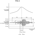
- FIG. 3 is a graph indicating the in-cylinder pressures with respect to the crank angles
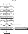
- FIG. 4 is a flowchart illustrating an engine-knocking determining method.
- the engine-knocking determining method includes: a step of acquiring pressure amplitudes of the main-combustion chamber 22; a step of delimiting the pressure amplitudes acquired into the first section and the second section, the first section being a section prior to the maximum in-cylinder pressure and the second section being a section subsequent to the maximum in-cylinder pressure; a step of determining whether knocking has occurred, by comparing a first maximum amplitude of the pressure amplitude in the first section with a second maximum amplitude of the pressure amplitude in the second section.
- the solid line in the upper part represents the in-cylinder pressures detected by the in-cylinder pressure sensor 42
- the solid line in the lower part represents the amplitudes of the pressures in the main-combustion chamber obtained by processing the in-cylinder pressures with the filter processing unit 51.
- a first section TW1 delimited by the section delimiting unit 52 corresponds to a period from a timing prior to the start of combustion to the time tpmax; and a second section TW2 corresponds to a period from the time tpmax to a timing subsequent to the end of the combustion.
- the pressure amplitudes in the first section TW1 come to represent vibrations without the effect of knocking
- the pressure amplitudes in the second section come to represent vibrations affected by knocking, when such knocking has occurred.
- the first maximum amplitude calculating unit 53 calculates the first maximum amplitude P1 by subtracting the minimum in-cylinder pressure Pt1-max from the maximum in-cylinder pressure Pt1+max, in the first section.
- the second maximum amplitude calculating unit 54 calculates the second maximum amplitude P2 by subtracting the minimum in-cylinder pressure Pt2-max from the maximum in-cylinder pressure Pt2+max in the second section.
- the determining unit 55 determines whether knocking has occurred, by comparing the first maximum amplitude P1 in the first section TW1 with the second maximum amplitude P2 in the second section TW2. In other words, the determining unit 55 determines that knocking has occurred when P2/P1 that is the ratio of the second maximum amplitude P2 to the first maximum amplitude P1 is greater than a ratio threshold Pj. In other words, the determining unit 55 determines that knocking has occurred when the second maximum amplitude P2 in the second section is too large.
- the knocking determining device 40 collects the in-cylinder pressures detected by the in-cylinder pressure sensor 42.
- the filter processing unit 51 applies filtering to the in-cylinder pressures to calculate the pressure amplitudes of the main-combustion chamber 22 with respect to the crank angle (time).
- the section delimiting unit 52 delimits the first section TW1 and the second section TW2 using the time (crank angle) tpmax as a boundary at which the maximum in-cylinder pressure Pmax is reached.
- the first maximum amplitude calculating unit 53 calculates the first maximum amplitude P1 in the first section by subtracting the minimum in-cylinder pressure Pt1-max at the first maximum amplitude P1 from the maximum in-cylinder pressure Pt1+max at the first maximum amplitude P1.
- the second maximum amplitude calculating unit 54 calculates the second maximum amplitude P2 in the second section by subtracting the minimum in-cylinder pressure Pt2-max at the second maximum amplitude P2 from the maximum in-cylinder pressure Pt2+max at the second maximum amplitude P2.
- the determining unit 55 determines whether knocking has occurred, by comparing the first maximum amplitude P1 in the first section TW1 with the second maximum amplitude P2 in the second section TW2. In other words, the determining unit 55 determines whether P2/P1 that is the ratio of the second maximum amplitude P2 to the first maximum amplitude P1 is greater than the ratio threshold Pj (e.g., 1.3). If the determining unit 55 determines that P2/P1 that is the ratio of the second maximum amplitude P2 to the first maximum amplitude P1 is greater than the ratio threshold Pj (Yes), the determining unit 55 determines that knocking has occurred, at Step S17.
- the ratio threshold Pj e.g., 1.3
- the determining unit 55 determines that P2/P1 that is the ratio of the second maximum amplitude P2 to the first maximum amplitude P1 is not greater than the ratio threshold Pj (No), the determining unit 55 determines that no knocking has occurred, at Step S18.
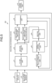
- FIG. 5 is schematic diagram illustrating a configuration of an engine-knocking determining device according to a second embodiment. Members having similar functions as those described in the first embodiment are given the same reference signs, and the detailed description thereof is omitted.
- the combustion gas in the pre-combustion chamber 32 is discharged as fire source into the main-combustion chamber 22, so that the air-fuel mixture compressed in the main-combustion chamber 22 is combusted.
- the air-fuel mixture ignites spontaneously before the frame spreads and knocking occurs. In such a case, knocking might occur before the in-cylinder pressure reaches the maximum value.
- knocking determination errors are suppressed by correcting the periods corresponding to the first section and the second section, when it is expected that knocking occurs at an earlier timing.
- a knocking determining device 40A includes a time difference calculating unit 61, a determination error evaluating unit 63, and a section correcting unit 64, in addition to the filter processing unit 51, the section delimiting unit 52, the first maximum amplitude calculating unit 53, the second maximum amplitude calculating unit 54, and the determining unit 55.
- the time difference calculating unit 61 calculates the difference in time, that is, a time difference, between the timing at which the maximum in-cylinder pressure in the first section is reached and the timing at which the maximum in-cylinder pressure in the second section is reached.
- the determination error evaluating unit 63 determines that the absolute value of the time difference is smaller than a time difference threshold, the determination error evaluating unit 63 evaluates that the determination that no knocking has occurred may be an error. In such a case, the section correcting unit 64 corrects the first section and the second section.
- the determination error evaluating unit 63 sets the time difference threshold to a half to the whole of the time difference between the timings of the maximum in-cylinder pressure and the minimum in-cylinder pressure when the pressure amplitude becomes the maximum, across the entire section including the first section and the second section.
- the time difference threshold is a control value between a half and the whole of the absolute value of the subtraction of the time of the minimum in-cylinder pressure from the time of the maximum in-cylinder pressure.
- the time difference threshold corresponds to 1/4 cycle to 1/2 cycle of the pressure.
- the section correcting unit 64 corrects the position of the boundary between the first section and the second section on the basis of the time difference threshold (the control value corresponding to a 1/4 cycle to a 1/2 cycle of the pressure waveform), without changing the interval widths of the first section and the second section. It is preferable that the section correcting unit 64 shift the position of the boundary between the first section and the second section toward the first section by the time difference threshold (the control value corresponding to a 1/4 cycle to a 1/2 cycle of the pressure waveform), but the section correcting unit 64 is not limited by this method.
- the section correcting unit 64 may shift the position of the boundary between the first section and the second section toward the first section, within the range between 1/4 the cycle of the pressure waveform and 1/2 the cycle of the pressure waveform.
- the processes of the first maximum amplitude calculating unit 53, the second maximum amplitude calculating unit 54, and the determining unit 55 are performed again.
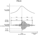
- FIG. 6 is a graph indicating the in-cylinder pressures and a heat release rate with respect to the crank angles
- FIG. 7 is a flowchart illustrating an engine-knocking determining method.
- the solid line in the upper part represents in-cylinder pressures detected by the in-cylinder pressure sensor 42; the solid line in the middle part represents a heat release rate of the main-combustion chamber, the heat release rate being calculated from the in-cylinder pressures; and the solid line in the lower part represents pressures in the main-combustion chamber obtained by processing the in-cylinder pressures with the filter processing unit 51.
- the in-cylinder pressure reaches the maximum in-cylinder pressure Pmax at the time (crank angle) tpmax; therefore, the first section TW1 delimited by the section delimiting unit 52 corresponds to a period from a timing prior to the start of combustion to the time tpmax, and the second section TW2 corresponds to a period from the time tpmax to a timing subsequent to the end of combustion.
- the time difference calculating unit 61 calculates the absolute value of the difference in time, that is, a time difference tm between the time tp1+max at which the maximum in-cylinder pressure Pt1+max in the first section is reached and the time tp2+max at which the maximum in-cylinder pressure in the second section is reached (
- the determination error evaluating unit 63 determines that the time difference tm is smaller than a time difference threshold tmj, the determination error evaluating unit 63 evaluates that the determination that no knocking has occurred may be an error.
- the determination error evaluating unit 63 sets the time difference threshold tmj to a half to the whole of the time difference twm between the time of the maximum in-cylinder pressure Pt+max and the time of the minimum in-cylinder pressure Pt-max when the pressure amplitude is maximum across the entire section including the first section TW1 and the second section TW2.
- the section correcting unit 64 then shifts the position of the boundary between the first section and the second section toward the first section TW1, by the time difference threshold (the control value corresponding to a 1/4 cycle to a 1/2 cycle of the pressure) tmj, as indicated by the long dashed short dashed line in FIG. 6 .
- Step S11 to Step S17 are the same as those in the first embodiment.
- the determining unit 55 determines that P2/P1 that is the ratio of the second maximum amplitude P2 to the first maximum amplitude P1 is not greater than the ratio threshold Pj (No)
- the determining unit 55 determines that no knocking has occurred, at Step S18.
- the determination that no knocking has occurred may be an error. Therefore, at Step S21, the time difference calculating unit 61 calculates the absolute value of the difference in time, that is, the time difference tm, between time tp1+max at which the maximum in-cylinder pressure Pt1+max in the first section is reached and the time tp2+max at which the maximum in-cylinder pressure Pt2+max in the second section is reached.
- the determination error evaluating unit 63 determines whether the time difference tm is shorter than the time difference threshold tmj. If the determination error evaluating unit 63 determines that the time difference tm is not shorter than the time difference threshold tmj (No), the determination of the occurrence of knocking is regarded as correct, and the processing exits the routine. By contrast, if the determination error evaluating unit 63 determines that the time difference tm is shorter than the time difference threshold tmj (Yes), the determination of the occurrence of knocking is regarded as incorrect, and the processing goes to Step S23.
- the section correcting unit 64 shifts the position of the boundary between the first section and the second section toward the first section TW1, by the time difference threshold (the control value corresponding to a 1/4 cycle to a 1/2 cycle of the pressure waveform) tmj, without changing the interval widths of the first section and the second section.
- An engine-knocking determining device includes: a filter processing unit (pressure amplitude acquiring unit) 51 that acquires pressure amplitudes of the main-combustion chamber (main chamber) 22; a section delimiting unit 52 that delimits the pressure amplitudes acquired by the filter processing unit 51 into a first section prior to a maximum in-cylinder pressure and a second section subsequent to the maximum in-cylinder pressure; and a determining unit 55 that determines whether knocking has occurred, by comparing a first maximum amplitude of the pressure amplitude in the first section with a second maximum amplitude of the pressure amplitude in the second section.
- the section delimiting unit 52 delimits the first section and the second section using the timing as a boundary at which the maximum in-cylinder pressure is reached.
- the pressure amplitudes in the first section represent vibrations without the effect of knocking
- the pressure amplitudes in the second section represent vibrations affected by knocking, when such knocking has occurred.
- the determining unit 55 determines that knocking has occurred, when a ratio between the first maximum amplitude and the second maximum amplitude is greater than a preset ratio threshold. In this manner, it becomes possible to easily determine the occurrence of knocking.
- An engine-knocking determining device includes a section correcting unit 64 that corrects the first section and the second section in a case where a time difference between a timing at which the maximum in-cylinder pressure in the first section is reached and a timing at which the maximum in-cylinder pressure in the second section is reached is shorter than a preset time difference threshold when the ratio between the first maximum amplitude and the second maximum amplitude in the first section or the second section is equal to or lower than an amplitude threshold.
- the section correcting unit 64 corrects the first section and the second section even during an engine operation in which knocking occurs at an early stage, it is possible to determine the occurrence of knocking highly accurately.
- the time difference threshold is set to 1/2 a time difference between a timing of the maximum in-cylinder pressure and a timing of the minimum in-cylinder pressure when the pressure amplitude becomes the maximum, across the entire section including the first section and the second section. In this manner, it becomes possible to determine the occurrence of engine-knocking appropriately.
- the section correcting unit 64 corrects a position of a boundary between the first section and the second section, based on the time difference threshold, by a time difference corresponding to 1/4 a cycle of a pressure amplitude waveform. In this manner, it is possible to correct the first section and the second section appropriately.
- An engine-knocking determining method includes: a step of acquiring pressure amplitudes of the main-combustion chamber 22; a step of delimiting the pressure amplitudes acquired into the first section and the second section, the first section being a section prior to the maximum in-cylinder pressure and the second section being a section subsequent to the maximum in-cylinder pressure; a step determining whether knocking has occurred by comparing the first maximum amplitude of the pressure amplitude in the first section with the second maximum amplitude of the pressure amplitude in the second section.
- the pressure amplitudes in the first section represent vibrations without the effect of knocking
- the pressure amplitudes in the second section represent vibrations affected by knocking, when such knocking has occurred.
- the determining unit 55 can determine that knocking has occurred appropriately, with the effects of the torch jet removed from the first section and the second section. As a result, it is possible to improve knocking determination accuracy.
Landscapes
- Engineering & Computer Science (AREA)
- Chemical & Material Sciences (AREA)
- Combustion & Propulsion (AREA)
- Mechanical Engineering (AREA)
- General Engineering & Computer Science (AREA)
- Physics & Mathematics (AREA)
- General Physics & Mathematics (AREA)
- Signal Processing (AREA)
- Combined Controls Of Internal Combustion Engines (AREA)
- Combustion Methods Of Internal-Combustion Engines (AREA)
Abstract
Description
- The present disclosure relates to an engine-knocking determining device and method.
- In engines causing combustion using flame propagation, the pressure or temperature of unburned gas increases as the combustion progresses, and combustion due to spontaneous ignition, or what is called knocking, may occur before flame propagation. In the engine, knocking may cause a pressure wave in the combustion chamber, and members of the combustion chamber, such as a piston, may be damaged. At the same time, in order to improve the thermal efficiency of the engine, it is effective to advance the timing of ignition. However, as the timing of ignition is advanced, the chance of occurrence of knocking increases, and therefore, knocking becomes a limiting factor in the ignition timing advance. Hence, it is extremely important to make a highly accurate determination whether knocking has occurred in an engine.
- One example of a conventional engine-knocking determining device is disclosed in Patent Literature 1 cited below. The knocking determining device disclosed in Patent Literature 1 applies filtering to the detected pressures in the cylinder, evaluates the amplitudes of the pressure (in-cylinder pressure), and determines that knocking has occurred when the pressure amplitude reaches a level equal to or higher than a control value.
- Patent Literature 1:
Japanese Patent Application Laid-open No. H10-205386 - A pre-chamber gas engine with a cylinder head provided with an ignition pre-chamber is known. In such pre-chamber engine, air-fuel mixture that is a mixture of fuel and air is supplied into the main-combustion chamber, and fuel is supplied to the pre-chamber. While a piston compresses the air-fuel mixture in the main-combustion chamber, the fuel in the pre-chamber is ignited by a spark plug, and thus flame is discharged into the main-combustion chamber, so that the flame ignites the air-fuel mixture in the main-combustion chamber and propagates therein. In such a pre-chamber gas engine, as the flame in the pre-chamber is discharged into the main-combustion chamber, the torch jet discharged generates a pressure wave. Therefore, when it is determined whether knocking has occurred, the pressure wave resultant of the torch jet discharged may affect the pressure amplitude as acoustic noise, and may cause an error in the determination of the occurrence of knocking.
- The present disclosure is aimed to solve the problem described above, and an object of the present disclosure is to provide an engine-knocking determining device and method to improve knocking determination accuracy.
- To achieve the above-described object, an engine-knocking determining device according to the present disclosure is for a pre-chamber engine that causes combustion by discharging flame in a pre-chamber into a main chamber, and includes: a pressure amplitude acquiring unit that acquires pressure amplitudes of the main chamber; a section delimiting unit that delimits the pressure amplitudes acquired by the pressure amplitude acquiring unit into a first section prior to a maximum in-cylinder pressure and a second section subsequent to the maximum in-cylinder pressure; and a determining unit that determines whether knocking has occurred, by comparing a first maximum amplitude of the pressure amplitude in the first section with a second maximum amplitude of the pressure amplitude in the second section.
- Further, an engine-knocking determining method according to the present disclosure is for a pre-chamber engine that causes combustion by discharging flame in a pre-chamber into a main chamber, and includes the steps of: acquiring pressure amplitudes of the main chamber; delimiting the pressure amplitudes acquired into a first section prior to a maximum in-cylinder pressure and a second section subsequent to the maximum in-cylinder pressure; and determining whether knocking has occurred, by comparing a first maximum amplitude of the pressure amplitude in the first section with a second maximum amplitude of the pressure amplitude in the second section.
- With the engine-knocking determining device and method according to the present disclosure, it is possible to improve knocking determination accuracy.
-
-
FIG. 1 is a schematic diagram illustrating an internal configuration of a pre-chamber gas engine. -
FIG. 2 is schematic diagram illustrating a configuration of an engine-knocking determining device according to a first embodiment. -
FIG. 3 is a graph indicating in-cylinder pressures with respect to crank angles. -
FIG. 4 is a flowchart illustrating an engine-knocking determining method. -
FIG. 5 is a schematic diagram illustrating a configuration of an engine-knocking determining device according to a second embodiment. -
FIG. 6 is a graph indicating in-cylinder pressures with respect to crank angles. -
FIG. 7 is a flowchart illustrating an engine-knocking determining method. - Preferred embodiments of the present disclosure will now be explained in detail with reference to drawings. The embodiments are, however, not intended to limit the present disclosure, and when there are a plurality of embodiments, combinations thereof are also included in the present disclosure. Furthermore, elements described in the embodiment include those that can be easily thought of by those skilled in the art, those that are substantially identical thereto, and those falling within what is called the scope of equivalence.
-
FIG. 1 is a schematic diagram illustrating an internal configuration of a pre-chamber gas engine. - As illustrated in
FIG. 1 , an engine according to a first embodiment is apre-chamber gas engine 10. In the description of the first embodiment, the engine is thepre-chamber gas engine 10, but the engine may be any engine of another type, as long as the engine has a main chamber and a pre-chamber. Thepre-chamber gas engine 10 includes acylinder block 11, acylinder head 12, and apiston 13. - The
cylinder block 11 has a block-like shape, and has a cylindrical space extending in the vertical direction. Acylinder liner 21 is fitted to the space. Along the horizontal direction of thecylinder block 11, a plurality of the spaces, although not illustrated, are provided at a certain interval. Thecylinder head 12 is disposed on top of thecylinder block 11, and is fastened, with a plurality of bolts (not illustrated), to thecylinder block 11. - The
piston 13 has a cylindrical shape, and is disposed in thecylinder liner 21 in thecylinder block 11, and supported movably in the axial direction. Although illustration is omitted, a crank shaft is rotatably supported on a component below thecylinder block 11 and is connected to the piston 14 via a connecting rod. - A main-combustion chamber (main chamber) 22 is a space defined by the inner circumferential surface of the
cylinder liner 21 in thecylinder block 11, the bottom surface of thecylinder head 12, and the top surface of thepiston 13. Thecylinder head 12 is provided with anintake port 23 and anexhaust port 24, and one end of theintake port 23 and one end of theexhaust port 24 are connected to the main-combustion chamber 22. A bottom end of anintake valve 25 is disposed in theintake port 23, and a bottom end of anexhaust valve 26 is disposed in theexhaust port 24. Theintake valve 25 and theexhaust valve 26 are supported by thecylinder head 12 in a manner movable in the axial direction, and are biased, by a biasing member (not illustrated), in the direction (upwards inFIG. 1 ) in which theintake valve 25 and theexhaust valve 26 close theintake port 23 and theexhaust port 24, respectively. By the actions of an intake cam and an exhaust cam, not illustrated, theintake valve 25 and theexhaust valve 26 open theintake port 23 and theexhaust port 24, respectively, so that the air-fuel mixture that is a mixture of fuel gas and air is supplied into the main-combustion chamber 22. - On the bottom surface of the
cylinder head 12 that faces an upper part of the main-combustion chamber 22, apre-chamber cap 31 is attached. Thepre-chamber cap 31 is positioned at the center of the main-combustion chamber 22 in the radial direction, and protrudes into the main-combustion chamber 22. Thepre-chamber cap 31 is provided with a pre-combustion chamber (pre-chamber) 32 therein, and has a plurality oforifices 33 formed on the part protruding into the main-combustion chamber 22, at some interval therebetween along the circumferential direction of the protruding part of thepre-chamber cap 31. Theorifices 33 connect thepre-combustion chamber 32 to the main-combustion chamber 22. - The
cylinder head 12 also includes apre-chamber holder 34 fitted above thepre-chamber cap 31. Thepre-chamber holder 34 has a cylindrical shape, and apre-chamber gas valve 35 is disposed in thepre-chamber holder 34. Thepre-chamber gas valve 35 is opened during the intake stroke to supply the fuel gas into thepre-combustion chamber 32. Thecylinder head 12 also has aspark plug 36 fitted between thepre-chamber cap 31 and thepre-chamber holder 34. Thespark plug 36 is capable of igniting the air-fuel mixture containing fuel supplied into thepre-combustion chamber 32. - The
pre-chamber gas engine 10 goes through four strokes including an intake stroke, a compression stroke, a power stroke, and an exhaust stroke, while the crank shaft is rotated twice. During the strokes, an intake cam shaft and an exhaust cam shaft are rotated once and thereby theintake valve 25 and theexhaust valve 26 open and close theintake port 23 and theexhaust port 24, respectively. Once the air-fuel mixture is supplied through theintake port 23 into the main-combustion chamber 22, thepiston 13 is moved up to compress the air-fuel mixture. - The
pre-chamber gas valve 35 supplies fuel gas into thepre-combustion chamber 32. Thespark plug 36 ignites the fuel gas supplied into thepre-combustion chamber 32. Thus the fuel gas in thepre-combustion chamber 32 is combusted, and thereby combustion gas is generated. The combustion gas in thepre-combustion chamber 32 is then discharged through theorifices 33 into the main-combustion chamber 22, as fire source (torch). The air-fuel mixture compressed in the main-combustion chamber 22 is combusted by the fire source from thepre-combustion chamber 32. The explosion load produced by the combustion pushes down thepiston 13, and causes the crank shaft to rotate. The combustion gas generated in the main-combustion chamber 22 is then discharged as flue gas through theexhaust port 24. -
FIG. 2 is schematic diagram illustrating a configuration of an engine-knocking determining device according to the first embodiment. - As illustrated in
FIG. 2 , to a knocking determiningdevice 40, a crank angle sensor 41 and an in-cylinder pressure sensor 42 are connected. The crank angle sensor 41 detects the rotational angle of the crank shaft (a phase in 360 degrees), and outputs the rotational angle to the knocking determiningdevice 40. In other words, the crank angle sensor 41 detects the rotational angle of the crank shaft with reference to a top dead center. For example, the crank shaft has a disk fixed thereto, the disk having a plurality of slits that are spaced apart from each other in the circumferential direction. An optical sensor or an electromagnetic sensor then detects the rotating disk, and outputs the crank position (rotational angle). The in-cylinder pressure sensor 42 detects the pressure in the main-combustion chamber 22 (hereinafter referred to as an in-cylinder pressure) (seeFIG. 1 ), and outputs the pressure to the knocking determiningdevice 40. One example of the in-cylinder pressure sensor 42 is a high-temperature piezoelectric pressure sensor mounted on the cylinder head. - The knocking determining
device 40 is also connected to anengine control unit 43. The knocking determiningdevice 40 outputs knocking determination result representing whether knocking has occurred in thepre-chamber gas engine 10 to theengine control unit 43. Based on the knocking determination result, theengine control unit 43 performs control such as the advance of ignition timing in thepre-chamber gas engine 10. - The knocking determining
device 40 and theengine control unit 43 are control devices. The control devices serving as the knocking determiningdevice 40 and theengine control unit 43 are controllers, and are implemented by causing a central processing unit (CPU) or a micro-processing unit (MPU) to execute various computer programs stored in a storage, using a RAM as a working area. The knocking determiningdevice 40 and theengine control unit 43 may also be implemented as one control device. - The knocking determining
device 40 includes a filter processing unit (pressure amplitude acquiring unit) 51, asection delimiting unit 52, a first maximumamplitude calculating unit 53, a second maximumamplitude calculating unit 54, and a determiningunit 55. - The
filter processing unit 51 is a band-pass filter, and removes a low-frequency component and a high-frequency component from the in-cylinder pressure detected by the in-cylinder pressure sensor 42, using certain frequencies, to obtain the pressure amplitude at a particular frequency. In other words, thefilter processing unit 51 acquires a temporal change in the amplitude of the pressure in the main-combustion chamber 22, with respect to the crank angle (time). - The
section delimiting unit 52 delimits the changes of the amplitudes of the pressures in the main-combustion chamber 22 with respect to the crank angles acquired by thefilter processing unit 51 into a first section and a second section. The first section herein is a temporal section prior to the maximum in-cylinder pressure, and the second section is a temporal section subsequent to the maximum in-cylinder pressure. The timing to start the first section is, for example, a timing prior to the start of combustion, and the timing to end the second section is a timing subsequent to the end of combustion. In other words, the first section is a period from a timing prior to the start of the combustion to a timing at which the maximum in-cylinder pressure is reached, and the second section is a period from the timing at which the maximum in-cylinder pressure is reached to a timing subsequent to the end of the combustion. - The first maximum
amplitude calculating unit 53 calculates a first maximum amplitude, from the change in the amplitude of the pressure in the first section. In other words, the first maximumamplitude calculating unit 53 calculates the difference between the maximum in-cylinder pressure and the minimum in-cylinder pressure at the maximum amplitude in the first section, as the first maximum amplitude. The second maximumamplitude calculating unit 54 calculates a second maximum amplitude, from the change in the amplitude of the pressure in the second section. In other words, the second maximumamplitude calculating unit 54 calculates the difference between the maximum in-cylinder pressure and the minimum in-cylinder pressure at the maximum amplitude in the second section, as the second maximum amplitude. The amplitude herein is the difference between a peak and a valley (or valley and peak) that are adjacent to each other in a pressure waveform. The amplitude is not limited to such a difference, but may also be a difference between a peak or a valley prior to or subsequent to the boundary and the pressure at the boundary between the first section and the second section, for example. - The determining
unit 55 determines whether knocking has occurred, by comparing the first maximum amplitude in the first section with the second maximum amplitude in the second section. In other words, the determiningunit 55 determines that knocking has occurred when the ratio of the second maximum amplitude to the first maximum amplitude is greater than a preset ratio threshold. -
FIG. 3 is a graph indicating the in-cylinder pressures with respect to the crank angles, andFIG. 4 is a flowchart illustrating an engine-knocking determining method. - The engine-knocking determining method according to the first embodiment includes: a step of acquiring pressure amplitudes of the main-
combustion chamber 22; a step of delimiting the pressure amplitudes acquired into the first section and the second section, the first section being a section prior to the maximum in-cylinder pressure and the second section being a section subsequent to the maximum in-cylinder pressure; a step of determining whether knocking has occurred, by comparing a first maximum amplitude of the pressure amplitude in the first section with a second maximum amplitude of the pressure amplitude in the second section. - In
FIG. 3 , the solid line in the upper part represents the in-cylinder pressures detected by the in-cylinder pressure sensor 42, and the solid line in the lower part represents the amplitudes of the pressures in the main-combustion chamber obtained by processing the in-cylinder pressures with thefilter processing unit 51. - The in-cylinder pressure reaches a maximum in-cylinder pressure Pmax at time (crank angle) tpmax. Therefore, a first section TW1 delimited by the
section delimiting unit 52 corresponds to a period from a timing prior to the start of combustion to the time tpmax; and a second section TW2 corresponds to a period from the time tpmax to a timing subsequent to the end of the combustion. In other words, by delimiting the first section TW1 and the second section TW2, using the timing as a boundary at which the maximum in-cylinder pressure Pmax is reached, the pressure amplitudes in the first section TW1 come to represent vibrations without the effect of knocking, and the pressure amplitudes in the second section come to represent vibrations affected by knocking, when such knocking has occurred. - In the first section, a minimum in-cylinder pressure Pt1-max at the first maximum amplitude P1 is reached at time (crank angle) t1-max, and a maximum in-cylinder pressure Pt1+max at the first maximum amplitude P1 is reached at time (crank angle) t1+max. Therefore, the first maximum
amplitude calculating unit 53 calculates the first maximum amplitude P1 by subtracting the minimum in-cylinder pressure Pt1-max from the maximum in-cylinder pressure Pt1+max, in the first section. - In the second section, a maximum in-cylinder pressure Pt2+max at the second maximum amplitude P2 is reached at time (crank angle) t2+max, and a minimum in-cylinder pressure Pt2-max at the second maximum amplitude P2 is reached at time (crank angle) t2-max. Therefore, the second maximum
amplitude calculating unit 54 calculates the second maximum amplitude P2 by subtracting the minimum in-cylinder pressure Pt2-max from the maximum in-cylinder pressure Pt2+max in the second section. - The determining
unit 55 determines whether knocking has occurred, by comparing the first maximum amplitude P1 in the first section TW1 with the second maximum amplitude P2 in the second section TW2. In other words, the determiningunit 55 determines that knocking has occurred when P2/P1 that is the ratio of the second maximum amplitude P2 to the first maximum amplitude P1 is greater than a ratio threshold Pj. In other words, the determiningunit 55 determines that knocking has occurred when the second maximum amplitude P2 in the second section is too large. - The method for determining the occurrence of knocking will now be explained specifically. As illustrated in
FIGS. 2 and4 , at Step S11, the knocking determiningdevice 40 collects the in-cylinder pressures detected by the in-cylinder pressure sensor 42. At Step S12, thefilter processing unit 51 applies filtering to the in-cylinder pressures to calculate the pressure amplitudes of the main-combustion chamber 22 with respect to the crank angle (time). - At Step S13, the
section delimiting unit 52 delimits the first section TW1 and the second section TW2 using the time (crank angle) tpmax as a boundary at which the maximum in-cylinder pressure Pmax is reached. At Step S14, the first maximumamplitude calculating unit 53 calculates the first maximum amplitude P1 in the first section by subtracting the minimum in-cylinder pressure Pt1-max at the first maximum amplitude P1 from the maximum in-cylinder pressure Pt1+max at the first maximum amplitude P1. At Step S15, the second maximumamplitude calculating unit 54 calculates the second maximum amplitude P2 in the second section by subtracting the minimum in-cylinder pressure Pt2-max at the second maximum amplitude P2 from the maximum in-cylinder pressure Pt2+max at the second maximum amplitude P2. - At Step S16, the determining
unit 55 determines whether knocking has occurred, by comparing the first maximum amplitude P1 in the first section TW1 with the second maximum amplitude P2 in the second section TW2. In other words, the determiningunit 55 determines whether P2/P1 that is the ratio of the second maximum amplitude P2 to the first maximum amplitude P1 is greater than the ratio threshold Pj (e.g., 1.3). If the determiningunit 55 determines that P2/P1 that is the ratio of the second maximum amplitude P2 to the first maximum amplitude P1 is greater than the ratio threshold Pj (Yes), the determiningunit 55 determines that knocking has occurred, at Step S17. By contrast, if the determiningunit 55 determines that P2/P1 that is the ratio of the second maximum amplitude P2 to the first maximum amplitude P1 is not greater than the ratio threshold Pj (No), the determiningunit 55 determines that no knocking has occurred, at Step S18. -
FIG. 5 is schematic diagram illustrating a configuration of an engine-knocking determining device according to a second embodiment. Members having similar functions as those described in the first embodiment are given the same reference signs, and the detailed description thereof is omitted. - As illustrated in
FIG. 1 , in thepre-chamber gas engine 10, the combustion gas in thepre-combustion chamber 32 is discharged as fire source into the main-combustion chamber 22, so that the air-fuel mixture compressed in the main-combustion chamber 22 is combusted. In the main-combustion chamber 22, sometimes the air-fuel mixture ignites spontaneously before the frame spreads and knocking occurs. In such a case, knocking might occur before the in-cylinder pressure reaches the maximum value. In the second embodiment, knocking determination errors are suppressed by correcting the periods corresponding to the first section and the second section, when it is expected that knocking occurs at an earlier timing. - As illustrated in
FIG. 5 , a knocking determiningdevice 40A includes a timedifference calculating unit 61, a determinationerror evaluating unit 63, and asection correcting unit 64, in addition to thefilter processing unit 51, thesection delimiting unit 52, the first maximumamplitude calculating unit 53, the second maximumamplitude calculating unit 54, and the determiningunit 55. - The time
difference calculating unit 61 calculates the difference in time, that is, a time difference, between the timing at which the maximum in-cylinder pressure in the first section is reached and the timing at which the maximum in-cylinder pressure in the second section is reached. - When the determining
unit 55 determines that no knocking has occurred, if the determinationerror evaluating unit 63 determines that the absolute value of the time difference is smaller than a time difference threshold, the determinationerror evaluating unit 63 evaluates that the determination that no knocking has occurred may be an error. In such a case, thesection correcting unit 64 corrects the first section and the second section. - In such a case, the determination
error evaluating unit 63 sets the time difference threshold to a half to the whole of the time difference between the timings of the maximum in-cylinder pressure and the minimum in-cylinder pressure when the pressure amplitude becomes the maximum, across the entire section including the first section and the second section. In other words, the time difference threshold is a control value between a half and the whole of the absolute value of the subtraction of the time of the minimum in-cylinder pressure from the time of the maximum in-cylinder pressure. In other words, the time difference threshold corresponds to 1/4 cycle to 1/2 cycle of the pressure. - The
section correcting unit 64 corrects the position of the boundary between the first section and the second section on the basis of the time difference threshold (the control value corresponding to a 1/4 cycle to a 1/2 cycle of the pressure waveform), without changing the interval widths of the first section and the second section. It is preferable that thesection correcting unit 64 shift the position of the boundary between the first section and the second section toward the first section by the time difference threshold (the control value corresponding to a 1/4 cycle to a 1/2 cycle of the pressure waveform), but thesection correcting unit 64 is not limited by this method. Thesection correcting unit 64 may shift the position of the boundary between the first section and the second section toward the first section, within the range between 1/4 the cycle of the pressure waveform and 1/2 the cycle of the pressure waveform. - Once the first section and the second section are corrected by the
section correcting unit 64, the processes of the first maximumamplitude calculating unit 53, the second maximumamplitude calculating unit 54, and the determiningunit 55 are performed again. -
FIG. 6 is a graph indicating the in-cylinder pressures and a heat release rate with respect to the crank angles, andFIG. 7 is a flowchart illustrating an engine-knocking determining method. - In
FIG. 6 , the solid line in the upper part represents in-cylinder pressures detected by the in-cylinder pressure sensor 42; the solid line in the middle part represents a heat release rate of the main-combustion chamber, the heat release rate being calculated from the in-cylinder pressures; and the solid line in the lower part represents pressures in the main-combustion chamber obtained by processing the in-cylinder pressures with thefilter processing unit 51. - The in-cylinder pressure reaches the maximum in-cylinder pressure Pmax at the time (crank angle) tpmax; therefore, the first section TW1 delimited by the
section delimiting unit 52 corresponds to a period from a timing prior to the start of combustion to the time tpmax, and the second section TW2 corresponds to a period from the time tpmax to a timing subsequent to the end of combustion. - When the knocking occurs at an earlier stage, the maximum in-cylinder pressure Pt1+max in the first section TW1 becomes the same as the maximum in-cylinder pressure Pt2+max in the second section TW2. Therefore, the time
difference calculating unit 61 calculates the absolute value of the difference in time, that is, a time difference tm between the time tp1+max at which the maximum in-cylinder pressure Pt1+max in the first section is reached and the time tp2+max at which the maximum in-cylinder pressure in the second section is reached (|tp2max+tp1+max|). - When the determining
unit 55 determines that no knocking has occurred, if the determinationerror evaluating unit 63 determines that the time difference tm is smaller than a time difference threshold tmj, the determinationerror evaluating unit 63 evaluates that the determination that no knocking has occurred may be an error. In other words, if the time tp1+max at which the maximum in-cylinder pressure Pt1+max in the first section is reached is the same time as the time tp2+max at which the maximum in-cylinder pressure Pt2+max in the second section is reached, the timedifference calculating unit 61 derives the time difference tm=0. Therefore, the determinationerror evaluating unit 63 determines that the time difference tm is smaller than time difference threshold tmj, and evaluates that the determination that no knocking has occurred may be an error. - In such a case, the determination
error evaluating unit 63 sets the time difference threshold tmj to a half to the whole of the time difference twm between the time of the maximum in-cylinder pressure Pt+max and the time of the minimum in-cylinder pressure Pt-max when the pressure amplitude is maximum across the entire section including the first section TW1 and the second section TW2. Thesection correcting unit 64 then shifts the position of the boundary between the first section and the second section toward the first section TW1, by the time difference threshold (the control value corresponding to a 1/4 cycle to a 1/2 cycle of the pressure) tmj, as indicated by the long dashed short dashed line inFIG. 6 . - The method for determining the occurrence of knocking will now be explained specifically. As illustrated in
FIGS. 2 and7 , the processes from Step S11 to Step S17 are the same as those in the first embodiment. - At Step S16, if the determining
unit 55 determines that P2/P1 that is the ratio of the second maximum amplitude P2 to the first maximum amplitude P1 is not greater than the ratio threshold Pj (No), the determiningunit 55 determines that no knocking has occurred, at Step S18. However, the determination that no knocking has occurred may be an error. Therefore, at Step S21, the timedifference calculating unit 61 calculates the absolute value of the difference in time, that is, the time difference tm, between time tp1+max at which the maximum in-cylinder pressure Pt1+max in the first section is reached and the time tp2+max at which the maximum in-cylinder pressure Pt2+max in the second section is reached. - At Step S22, the determination
error evaluating unit 63 determines whether the time difference tm is shorter than the time difference threshold tmj. If the determinationerror evaluating unit 63 determines that the time difference tm is not shorter than the time difference threshold tmj (No), the determination of the occurrence of knocking is regarded as correct, and the processing exits the routine. By contrast, if the determinationerror evaluating unit 63 determines that the time difference tm is shorter than the time difference threshold tmj (Yes), the determination of the occurrence of knocking is regarded as incorrect, and the processing goes to Step S23. At Step S23, thesection correcting unit 64 shifts the position of the boundary between the first section and the second section toward the first section TW1, by the time difference threshold (the control value corresponding to a 1/4 cycle to a 1/2 cycle of the pressure waveform) tmj, without changing the interval widths of the first section and the second section. - After the
section correcting unit 64 corrects the first section and the second section at Step S23, the processing goes back to Step S14, and the processes at Step S14 and thereafter are repeated. - An engine-knocking determining device according to a first aspect included in a
pre-chamber gas engine 10 that causes combustion by discharging flame in a pre-combustion chamber (pre-chamber) 32 into a main-combustion chamber 22 includes: a filter processing unit (pressure amplitude acquiring unit) 51 that acquires pressure amplitudes of the main-combustion chamber (main chamber) 22; asection delimiting unit 52 that delimits the pressure amplitudes acquired by thefilter processing unit 51 into a first section prior to a maximum in-cylinder pressure and a second section subsequent to the maximum in-cylinder pressure; and a determiningunit 55 that determines whether knocking has occurred, by comparing a first maximum amplitude of the pressure amplitude in the first section with a second maximum amplitude of the pressure amplitude in the second section. - With the engine-knocking determining device according to the first aspect, the
section delimiting unit 52 delimits the first section and the second section using the timing as a boundary at which the maximum in-cylinder pressure is reached. In other words, the pressure amplitudes in the first section represent vibrations without the effect of knocking, and the pressure amplitudes in the second section represent vibrations affected by knocking, when such knocking has occurred. By comparing the first maximum pressure amplitude of the pressure amplitude in the first section with the second maximum pressure amplitude of the pressure amplitude in the second section, the determiningunit 55 can determine that knocking has occurred appropriately, with the effects of the torch jet removed from the first section and the second section. As a result, it is possible to improve knocking determination accuracy. - In an engine-knocking determining device according to a second aspect, the determining
unit 55 determines that knocking has occurred, when a ratio between the first maximum amplitude and the second maximum amplitude is greater than a preset ratio threshold. In this manner, it becomes possible to easily determine the occurrence of knocking. - An engine-knocking determining device according to a third aspect includes a
section correcting unit 64 that corrects the first section and the second section in a case where a time difference between a timing at which the maximum in-cylinder pressure in the first section is reached and a timing at which the maximum in-cylinder pressure in the second section is reached is shorter than a preset time difference threshold when the ratio between the first maximum amplitude and the second maximum amplitude in the first section or the second section is equal to or lower than an amplitude threshold. In this manner, because thesection correcting unit 64 corrects the first section and the second section even during an engine operation in which knocking occurs at an early stage, it is possible to determine the occurrence of knocking highly accurately. - In an engine-knocking determining device according to a fourth aspect, the time difference threshold is set to 1/2 a time difference between a timing of the maximum in-cylinder pressure and a timing of the minimum in-cylinder pressure when the pressure amplitude becomes the maximum, across the entire section including the first section and the second section. In this manner, it becomes possible to determine the occurrence of engine-knocking appropriately.
- In an engine-knocking determining device according to the fifth aspect, the
section correcting unit 64 corrects a position of a boundary between the first section and the second section, based on the time difference threshold, by a time difference corresponding to 1/4 a cycle of a pressure amplitude waveform. In this manner, it is possible to correct the first section and the second section appropriately. - An engine-knocking determining method according to a sixth aspect includes: a step of acquiring pressure amplitudes of the main-
combustion chamber 22; a step of delimiting the pressure amplitudes acquired into the first section and the second section, the first section being a section prior to the maximum in-cylinder pressure and the second section being a section subsequent to the maximum in-cylinder pressure; a step determining whether knocking has occurred by comparing the first maximum amplitude of the pressure amplitude in the first section with the second maximum amplitude of the pressure amplitude in the second section. In other words, the pressure amplitudes in the first section represent vibrations without the effect of knocking, and the pressure amplitudes in the second section represent vibrations affected by knocking, when such knocking has occurred. By comparing the first maximum pressure amplitude of the pressure amplitude in the first section with the second maximum pressure amplitude of the pressure amplitude in the second section, the determiningunit 55 can determine that knocking has occurred appropriately, with the effects of the torch jet removed from the first section and the second section. As a result, it is possible to improve knocking determination accuracy. -
- 10
- Pre-chamber gas engine
- 11
- Cylinder block
- 12
- Cylinder head
- 13
- Piston
- 21
- Cylinder liner
- 22
- Main-combustion chamber (main chamber)
- 23
- Intake port
- 24
- Exhaust port
- 25
- Intake valve
- 26
- Exhaust valve
- 31
- Pre-chamber cap
- 32
- Pre-combustion chamber (pre-chamber)
- 33
- Orifice
- 34
- Pre-chamber holder
- 35
- Pre-chamber gas valve
- 36
- Spark plug
- 40, 40A
- Knocking determining device
- 41
- Crank angle sensor
- 42
- In-cylinder pressure sensor
- 43
- Engine control unit
- 51
- Filter processing unit (pressure amplitude acquiring unit)
- 52
- Section delimiting unit
- 53
- First maximum amplitude calculating unit
- 54
- Second maximum amplitude calculating unit
- 55
- Determining unit
- 61
- Time difference calculating unit
- 63
- Determination error evaluating unit
- 64
- Section correcting unit
Claims (6)
- An engine-knocking determining device for a pre-chamber engine that causes combustion by discharging flame in a pre-chamber into a main chamber, the engine-knocking determining device comprising:a pressure amplitude acquiring unit that acquires pressure amplitudes of the main chamber;a section delimiting unit that delimits the pressure amplitudes acquired by the pressure amplitude acquiring unit into a first section prior to a maximum in-cylinder pressure and a second section subsequent to the maximum in-cylinder pressure; anda determining unit that determines whether knocking has occurred, by comparing a first maximum amplitude of the pressure amplitude in the first section with a second maximum amplitude of the pressure amplitude in the second section.
- The engine-knocking determining device according to claim 1, wherein when a ratio between the first maximum amplitude and the second maximum amplitude is greater than a preset ratio threshold, the determining unit determines that knocking has occurred.
- The engine-knocking determining device according to claim 2, further comprising a section correcting unit that corrects the first section and the second section in a case where a time difference between a timing at which the maximum in-cylinder pressure in the first section is reached and a timing at which the maximum in-cylinder pressure in the second section is reached is shorter than a preset time difference threshold when the ratio between the first maximum amplitude and the second maximum amplitude in the first section or the second section is equal to or lower than an amplitude threshold.
- The engine-knocking determining device according to claim 3, wherein the time difference threshold is set to 1/2 a time difference between a timing of the maximum in-cylinder pressure and a timing of the minimum in-cylinder pressure across an entire section including the first section and the second section, the maximum in-cylinder pressure and the minimum in-cylinder pressure being pressures at which the pressure amplitude is at a maximum.
- The engine-knocking determining device according to claim 3 or 4, wherein the section correcting unit corrects a position of a boundary between the first section and the second section, based on the time difference threshold, by a time difference corresponding to 1/4 a cycle of a pressure amplitude waveform.
- An engine-knocking determining method for a pre-chamber engine that causes combustion by discharging flame in a pre-chamber into a main chamber, the engine-knocking determining method comprising the steps of:acquiring pressure amplitudes of the main chamber;delimiting the pressure amplitudes acquired into a first section prior to a maximum in-cylinder pressure and a second section subsequent to the maximum in-cylinder pressure; anddetermining whether knocking has occurred, by comparing a first maximum amplitude of the pressure amplitude in the first section with a second maximum amplitude of the pressure amplitude in the second section.
Applications Claiming Priority (2)
| Application Number | Priority Date | Filing Date | Title |
|---|---|---|---|
| JP2022028177A JP7770211B2 (en) | 2022-02-25 | 2022-02-25 | Apparatus and method for determining engine knocking |
| PCT/JP2023/005135 WO2023162805A1 (en) | 2022-02-25 | 2023-02-15 | Engine knocking determination device and method |
Publications (2)
| Publication Number | Publication Date |
|---|---|
| EP4461948A1 true EP4461948A1 (en) | 2024-11-13 |
| EP4461948A4 EP4461948A4 (en) | 2025-04-16 |
Family
ID=87765889
Family Applications (1)
| Application Number | Title | Priority Date | Filing Date |
|---|---|---|---|
| EP23759806.5A Pending EP4461948A4 (en) | 2022-02-25 | 2023-02-15 | Engine knocking determination device and method |
Country Status (5)
| Country | Link |
|---|---|
| US (1) | US20250155322A1 (en) |
| EP (1) | EP4461948A4 (en) |
| JP (1) | JP7770211B2 (en) |
| CN (1) | CN118715360A (en) |
| WO (1) | WO2023162805A1 (en) |
Family Cites Families (9)
| Publication number | Priority date | Publication date | Assignee | Title |
|---|---|---|---|---|
| JPH06280728A (en) * | 1993-03-30 | 1994-10-04 | Mazda Motor Corp | Knocking detector for engine |
| JP3954679B2 (en) * | 1997-01-20 | 2007-08-08 | ヤンマー株式会社 | Knock detection method |
| JP4397804B2 (en) | 2004-12-27 | 2010-01-13 | 本田技研工業株式会社 | Knock detection device |
| JP2007231903A (en) * | 2006-03-03 | 2007-09-13 | Yanmar Co Ltd | Knocking determining device for internal combustion engine |
| JP5496004B2 (en) | 2010-07-29 | 2014-05-21 | 三菱重工業株式会社 | Engine misfire detection apparatus and method |
| JP6541586B2 (en) * | 2016-01-22 | 2019-07-10 | 三菱重工業株式会社 | Knocking detection method, ignition timing control method and control system for internal combustion engine |
| CN110678638A (en) | 2017-10-27 | 2020-01-10 | 三菱重工发动机和增压器株式会社 | Knock detection method and knock detection device |
| JP6835317B2 (en) * | 2017-12-05 | 2021-02-24 | 大阪瓦斯株式会社 | Combustion state determination method for sub-chamber engine, sub-chamber engine, and engine system |
| JP7081420B2 (en) | 2018-09-19 | 2022-06-07 | 株式会社デンソー | Knock determination device and knock control device |
-
2022
- 2022-02-25 JP JP2022028177A patent/JP7770211B2/en active Active
-
2023
- 2023-02-15 EP EP23759806.5A patent/EP4461948A4/en active Pending
- 2023-02-15 CN CN202380022151.4A patent/CN118715360A/en active Pending
- 2023-02-15 WO PCT/JP2023/005135 patent/WO2023162805A1/en not_active Ceased
- 2023-02-15 US US18/838,448 patent/US20250155322A1/en active Pending
Also Published As
| Publication number | Publication date |
|---|---|
| EP4461948A4 (en) | 2025-04-16 |
| WO2023162805A1 (en) | 2023-08-31 |
| CN118715360A (en) | 2024-09-27 |
| JP2023124427A (en) | 2023-09-06 |
| JP7770211B2 (en) | 2025-11-14 |
| US20250155322A1 (en) | 2025-05-15 |
Similar Documents
| Publication | Publication Date | Title |
|---|---|---|
| US8720416B2 (en) | Methods and apparatus to detect and inhibit low-speed pre-ignition in an engine | |
| JP6262957B2 (en) | Operation method of internal combustion engine | |
| US10450970B2 (en) | Detecting and mitigating abnormal combustion characteristics | |
| JP6312618B2 (en) | Internal combustion engine control device and abnormal combustion detection method | |
| CN102667112B (en) | Identify the method and apparatus of not controlled combustion in internal-combustion engine | |
| JP2010106742A (en) | In-cylinder pressure measurement apparatus | |
| JP2014037835A (en) | Operation method for internal combustion engine | |
| CN110088448B (en) | Method of operating a gaseous fuel internal combustion engine | |
| US9903778B2 (en) | Methods and systems to derive knock sensor conditions | |
| US20150159569A1 (en) | Method and apparatus for detecting combustion phase of engine by angular acceleration signal and combustion data of single cylinder | |
| CN108474317A (en) | Method for knock detection, ignition timing control method and ITCS Ignition Timing Control System | |
| CN108730057A (en) | The abnormal combustion detection device of internal combustion engine | |
| CN114008311B (en) | Device and method for controlling an ignition device having a fuel supply precombustion chamber in an internal combustion engine | |
| JPWO2011036743A1 (en) | Control device for internal combustion engine | |
| JP2020037893A (en) | Failure diagnosis device for cylinder internal pressure sensor | |
| US20250155322A1 (en) | Engine-knocking determining device and method | |
| JP2013104371A (en) | Internal combustion engine control device | |
| JP2012207656A (en) | Control device of internal combustion engine | |
| JP5466098B2 (en) | Combustion state detection system for internal combustion engine | |
| US20200208587A1 (en) | Knocking detection method and knocking detection device | |
| JP2015014229A (en) | Abnormal combustion avoidance device for internal combustion engine | |
| JP2002364447A (en) | Knock detection device for internal combustion engine | |
| CN116472399B (en) | Internal combustion engine control device | |
| CN102252849B (en) | System and method for detecting ignition quality of fuel | |
| JPH02221662A (en) | Method of forming combustion control map |
Legal Events
| Date | Code | Title | Description |
|---|---|---|---|
| STAA | Information on the status of an ep patent application or granted ep patent |
Free format text: STATUS: THE INTERNATIONAL PUBLICATION HAS BEEN MADE |
|
| PUAI | Public reference made under article 153(3) epc to a published international application that has entered the european phase |
Free format text: ORIGINAL CODE: 0009012 |
|
| STAA | Information on the status of an ep patent application or granted ep patent |
Free format text: STATUS: REQUEST FOR EXAMINATION WAS MADE |
|
| 17P | Request for examination filed |
Effective date: 20240809 |
|
| AK | Designated contracting states |
Kind code of ref document: A1 Designated state(s): AL AT BE BG CH CY CZ DE DK EE ES FI FR GB GR HR HU IE IS IT LI LT LU LV MC ME MK MT NL NO PL PT RO RS SE SI SK SM TR |
|
| REG | Reference to a national code |
Ref country code: DE Ref legal event code: R079 Free format text: PREVIOUS MAIN CLASS: F02D0045000000 Ipc: F02D0035020000 |
|
| A4 | Supplementary search report drawn up and despatched |
Effective date: 20250317 |
|
| RIC1 | Information provided on ipc code assigned before grant |
Ipc: F02D 41/14 20060101ALN20250311BHEP Ipc: G01L 23/22 20060101ALI20250311BHEP Ipc: F02P 5/152 20060101ALI20250311BHEP Ipc: F02B 19/12 20060101ALI20250311BHEP Ipc: F02D 41/00 20060101ALI20250311BHEP Ipc: F02D 35/02 20060101AFI20250311BHEP |
|
| DAV | Request for validation of the european patent (deleted) | ||
| DAX | Request for extension of the european patent (deleted) |