EP4461940A1 - Engine desiccant racks, methods of installing the same, systems for preventing corrosion, and articulating contact structures - Google Patents
Engine desiccant racks, methods of installing the same, systems for preventing corrosion, and articulating contact structures Download PDFInfo
- Publication number
- EP4461940A1 EP4461940A1 EP24162702.5A EP24162702A EP4461940A1 EP 4461940 A1 EP4461940 A1 EP 4461940A1 EP 24162702 A EP24162702 A EP 24162702A EP 4461940 A1 EP4461940 A1 EP 4461940A1
- Authority
- EP
- European Patent Office
- Prior art keywords
- desiccant
- platform
- edge region
- rack
- housing
- Prior art date
- Legal status (The legal status is an assumption and is not a legal conclusion. Google has not performed a legal analysis and makes no representation as to the accuracy of the status listed.)
- Granted
Links
Images


Classifications
-
- B—PERFORMING OPERATIONS; TRANSPORTING
- B01—PHYSICAL OR CHEMICAL PROCESSES OR APPARATUS IN GENERAL
- B01D—SEPARATION
- B01D53/00—Separation of gases or vapours; Recovering vapours of volatile solvents from gases; Chemical or biological purification of waste gases, e.g. engine exhaust gases, smoke, fumes, flue gases, aerosols
- B01D53/02—Separation of gases or vapours; Recovering vapours of volatile solvents from gases; Chemical or biological purification of waste gases, e.g. engine exhaust gases, smoke, fumes, flue gases, aerosols by adsorption, e.g. preparative gas chromatography
- B01D53/04—Separation of gases or vapours; Recovering vapours of volatile solvents from gases; Chemical or biological purification of waste gases, e.g. engine exhaust gases, smoke, fumes, flue gases, aerosols by adsorption, e.g. preparative gas chromatography with stationary adsorbents
- B01D53/0407—Constructional details of adsorbing systems
- B01D53/0415—Beds in cartridges
-
- F—MECHANICAL ENGINEERING; LIGHTING; HEATING; WEAPONS; BLASTING
- F02—COMBUSTION ENGINES; HOT-GAS OR COMBUSTION-PRODUCT ENGINE PLANTS
- F02C—GAS-TURBINE PLANTS; AIR INTAKES FOR JET-PROPULSION PLANTS; CONTROLLING FUEL SUPPLY IN AIR-BREATHING JET-PROPULSION PLANTS
- F02C7/00—Features, components parts, details or accessories, not provided for in, or of interest apart form groups F02C1/00 - F02C6/00; Air intakes for jet-propulsion plants
-
- B—PERFORMING OPERATIONS; TRANSPORTING
- B64—AIRCRAFT; AVIATION; COSMONAUTICS
- B64F—GROUND OR AIRCRAFT-CARRIER-DECK INSTALLATIONS SPECIALLY ADAPTED FOR USE IN CONNECTION WITH AIRCRAFT; DESIGNING, MANUFACTURING, ASSEMBLING, CLEANING, MAINTAINING OR REPAIRING AIRCRAFT, NOT OTHERWISE PROVIDED FOR; HANDLING, TRANSPORTING, TESTING OR INSPECTING AIRCRAFT COMPONENTS, NOT OTHERWISE PROVIDED FOR
- B64F5/00—Designing, manufacturing, assembling, cleaning, maintaining or repairing aircraft, not otherwise provided for; Handling, transporting, testing or inspecting aircraft components, not otherwise provided for
- B64F5/50—Handling or transporting aircraft components
-
- B—PERFORMING OPERATIONS; TRANSPORTING
- B01—PHYSICAL OR CHEMICAL PROCESSES OR APPARATUS IN GENERAL
- B01D—SEPARATION
- B01D53/00—Separation of gases or vapours; Recovering vapours of volatile solvents from gases; Chemical or biological purification of waste gases, e.g. engine exhaust gases, smoke, fumes, flue gases, aerosols
- B01D53/26—Drying gases or vapours
-
- B—PERFORMING OPERATIONS; TRANSPORTING
- B01—PHYSICAL OR CHEMICAL PROCESSES OR APPARATUS IN GENERAL
- B01D—SEPARATION
- B01D53/00—Separation of gases or vapours; Recovering vapours of volatile solvents from gases; Chemical or biological purification of waste gases, e.g. engine exhaust gases, smoke, fumes, flue gases, aerosols
- B01D53/26—Drying gases or vapours
- B01D53/261—Drying gases or vapours by adsorption
-
- B—PERFORMING OPERATIONS; TRANSPORTING
- B64—AIRCRAFT; AVIATION; COSMONAUTICS
- B64F—GROUND OR AIRCRAFT-CARRIER-DECK INSTALLATIONS SPECIALLY ADAPTED FOR USE IN CONNECTION WITH AIRCRAFT; DESIGNING, MANUFACTURING, ASSEMBLING, CLEANING, MAINTAINING OR REPAIRING AIRCRAFT, NOT OTHERWISE PROVIDED FOR; HANDLING, TRANSPORTING, TESTING OR INSPECTING AIRCRAFT COMPONENTS, NOT OTHERWISE PROVIDED FOR
- B64F5/00—Designing, manufacturing, assembling, cleaning, maintaining or repairing aircraft, not otherwise provided for; Handling, transporting, testing or inspecting aircraft components, not otherwise provided for
- B64F5/40—Maintaining or repairing aircraft
-
- B—PERFORMING OPERATIONS; TRANSPORTING
- B64—AIRCRAFT; AVIATION; COSMONAUTICS
- B64F—GROUND OR AIRCRAFT-CARRIER-DECK INSTALLATIONS SPECIALLY ADAPTED FOR USE IN CONNECTION WITH AIRCRAFT; DESIGNING, MANUFACTURING, ASSEMBLING, CLEANING, MAINTAINING OR REPAIRING AIRCRAFT, NOT OTHERWISE PROVIDED FOR; HANDLING, TRANSPORTING, TESTING OR INSPECTING AIRCRAFT COMPONENTS, NOT OTHERWISE PROVIDED FOR
- B64F5/00—Designing, manufacturing, assembling, cleaning, maintaining or repairing aircraft, not otherwise provided for; Handling, transporting, testing or inspecting aircraft components, not otherwise provided for
- B64F5/60—Testing or inspecting aircraft components or systems
-
- B—PERFORMING OPERATIONS; TRANSPORTING
- B65—CONVEYING; PACKING; STORING; HANDLING THIN OR FILAMENTARY MATERIAL
- B65D—CONTAINERS FOR STORAGE OR TRANSPORT OF ARTICLES OR MATERIALS, e.g. BAGS, BARRELS, BOTTLES, BOXES, CANS, CARTONS, CRATES, DRUMS, JARS, TANKS, HOPPERS, FORWARDING CONTAINERS; ACCESSORIES, CLOSURES, OR FITTINGS THEREFOR; PACKAGING ELEMENTS; PACKAGES
- B65D81/00—Containers, packaging elements, or packages, for contents presenting particular transport or storage problems, or adapted to be used for non-packaging purposes after removal of contents
- B65D81/24—Adaptations for preventing deterioration or decay of contents; Applications to the container or packaging material of food preservatives, fungicides, pesticides or animal repellants
- B65D81/26—Adaptations for preventing deterioration or decay of contents; Applications to the container or packaging material of food preservatives, fungicides, pesticides or animal repellants with provision for draining away, or absorbing, or removing by ventilation, fluids, e.g. exuded by contents; Applications of corrosion inhibitors or desiccators
- B65D81/264—Adaptations for preventing deterioration or decay of contents; Applications to the container or packaging material of food preservatives, fungicides, pesticides or animal repellants with provision for draining away, or absorbing, or removing by ventilation, fluids, e.g. exuded by contents; Applications of corrosion inhibitors or desiccators for absorbing liquids
-
- B—PERFORMING OPERATIONS; TRANSPORTING
- B65—CONVEYING; PACKING; STORING; HANDLING THIN OR FILAMENTARY MATERIAL
- B65D—CONTAINERS FOR STORAGE OR TRANSPORT OF ARTICLES OR MATERIALS, e.g. BAGS, BARRELS, BOTTLES, BOXES, CANS, CARTONS, CRATES, DRUMS, JARS, TANKS, HOPPERS, FORWARDING CONTAINERS; ACCESSORIES, CLOSURES, OR FITTINGS THEREFOR; PACKAGING ELEMENTS; PACKAGES
- B65D85/00—Containers, packaging elements or packages, specially adapted for particular articles or materials
- B65D85/68—Containers, packaging elements or packages, specially adapted for particular articles or materials for machines, engines or vehicles in assembled or dismantled form
-
- F—MECHANICAL ENGINEERING; LIGHTING; HEATING; WEAPONS; BLASTING
- F01—MACHINES OR ENGINES IN GENERAL; ENGINE PLANTS IN GENERAL; STEAM ENGINES
- F01D—NON-POSITIVE DISPLACEMENT MACHINES OR ENGINES, e.g. STEAM TURBINES
- F01D25/00—Component parts, details, or accessories, not provided for in, or of interest apart from, other groups
- F01D25/28—Supporting or mounting arrangements, e.g. for turbine casing
- F01D25/285—Temporary support structures, e.g. for testing, assembling, installing, repairing; Assembly methods using such structures
-
- F—MECHANICAL ENGINEERING; LIGHTING; HEATING; WEAPONS; BLASTING
- F01—MACHINES OR ENGINES IN GENERAL; ENGINE PLANTS IN GENERAL; STEAM ENGINES
- F01D—NON-POSITIVE DISPLACEMENT MACHINES OR ENGINES, e.g. STEAM TURBINES
- F01D25/00—Component parts, details, or accessories, not provided for in, or of interest apart from, other groups
- F01D25/32—Collecting of condensation water; Drainage ; Removing solid particles
-
- B—PERFORMING OPERATIONS; TRANSPORTING
- B01—PHYSICAL OR CHEMICAL PROCESSES OR APPARATUS IN GENERAL
- B01D—SEPARATION
- B01D2253/00—Adsorbents used in seperation treatment of gases and vapours
- B01D2253/10—Inorganic adsorbents
- B01D2253/106—Silica or silicates
- B01D2253/11—Clays
-
- B—PERFORMING OPERATIONS; TRANSPORTING
- B01—PHYSICAL OR CHEMICAL PROCESSES OR APPARATUS IN GENERAL
- B01D—SEPARATION
- B01D2257/00—Components to be removed
- B01D2257/80—Water
-
- B—PERFORMING OPERATIONS; TRANSPORTING
- B01—PHYSICAL OR CHEMICAL PROCESSES OR APPARATUS IN GENERAL
- B01D—SEPARATION
- B01D2259/00—Type of treatment
- B01D2259/45—Gas separation or purification devices adapted for specific applications
- B01D2259/4566—Gas separation or purification devices adapted for specific applications for use in transportation means
- B01D2259/4575—Gas separation or purification devices adapted for specific applications for use in transportation means in aeroplanes or space ships
-
- B—PERFORMING OPERATIONS; TRANSPORTING
- B64—AIRCRAFT; AVIATION; COSMONAUTICS
- B64D—EQUIPMENT FOR FITTING IN OR TO AIRCRAFT; FLIGHT SUITS; PARACHUTES; ARRANGEMENT OR MOUNTING OF POWER PLANTS OR PROPULSION TRANSMISSIONS IN AIRCRAFT
- B64D27/00—Arrangement or mounting of power plants in aircraft; Aircraft characterised by the type or position of power plants
-
- F—MECHANICAL ENGINEERING; LIGHTING; HEATING; WEAPONS; BLASTING
- F01—MACHINES OR ENGINES IN GENERAL; ENGINE PLANTS IN GENERAL; STEAM ENGINES
- F01D—NON-POSITIVE DISPLACEMENT MACHINES OR ENGINES, e.g. STEAM TURBINES
- F01D25/00—Component parts, details, or accessories, not provided for in, or of interest apart from, other groups
- F01D25/002—Cleaning of turbomachines
-
- F—MECHANICAL ENGINEERING; LIGHTING; HEATING; WEAPONS; BLASTING
- F05—INDEXING SCHEMES RELATING TO ENGINES OR PUMPS IN VARIOUS SUBCLASSES OF CLASSES F01-F04
- F05D—INDEXING SCHEME FOR ASPECTS RELATING TO NON-POSITIVE-DISPLACEMENT MACHINES OR ENGINES, GAS-TURBINES OR JET-PROPULSION PLANTS
- F05D2260/00—Function
- F05D2260/60—Fluid transfer
- F05D2260/608—Aeration, ventilation, dehumidification or moisture removal of closed spaces
-
- F—MECHANICAL ENGINEERING; LIGHTING; HEATING; WEAPONS; BLASTING
- F05—INDEXING SCHEMES RELATING TO ENGINES OR PUMPS IN VARIOUS SUBCLASSES OF CLASSES F01-F04
- F05D—INDEXING SCHEME FOR ASPECTS RELATING TO NON-POSITIVE-DISPLACEMENT MACHINES OR ENGINES, GAS-TURBINES OR JET-PROPULSION PLANTS
- F05D2260/00—Function
- F05D2260/95—Preventing corrosion
Definitions
- the present disclosure relates to engine desiccant racks, methods of installing the same, systems for preventing corrosion, and articulating contact structures.
- Aerospace structures such as engine housings or cowlings, nacelles, rocket nozzles, and/or the like are susceptible to corrosion due to moisture build up within the structures. Accordingly, desiccant materials are commonly used to dehydrate aerospace structures during storage. The desiccant materials remove condensation and other moisture accumulated within the aerospace structure during use, such as during flight. Desiccant materials also may prevent condensation from accumulating within the aerospace structures during storage.
- Conventional systems for deploying desiccant materials typically include stacking bags containing desiccant materials in an opening of the aerospace structure (e.g., an engine inlet). Stacking bags containing desiccant materials in this manner results in underutilization of the desiccant material, as a large portion of the surface area of each bag is obscured, either by adjacent bags or by walls of the aerospace structure. These conventional systems typically result in desiccant utilization of less than 25%.
- an engine desiccant rack for suspending one or more bags of a desiccant material within a housing of an aerospace structure includes a platform comprising a first edge region and a second edge region opposite the first edge region.
- the platform is configured to contact a first portion of a nonplanar wall of the housing at the first edge region and a second portion of the nonplanar wall of the housing at the second edge region, such that the platform is suspended by the nonplanar wall.
- a system for preventing corrosion within a housing of a structure includes: a desiccant rack and one or more bags containing a desiccant material.
- the desiccant rack is the engine desiccant rack described above.
- each bag of the one or more bags containing a desiccant material is suspended from the platform such that a largest face of each bag is oriented parallel to a plane defined by an opening of the housing.
- a method of installing a desiccant rack, such as the desiccant rack described above, within a housing of an aerospace structure includes: installing a platform of the desiccant rack within the housing.
- installing the platform of the desiccant rack within the housing includes installing the platform such that first and second edge regions of the platform contact a nonplanar wall of the housing and the platform is suspended within the housing.
- an articulating contact structure suitable for inclusion in desiccant racks described above includes: a body and a pivotable joint.
- the body includes a central hub and at least three legs extending from the central hub.
- the pivotable joint is coupled to the central hub opposite the at least three legs.
- Apparatuses and methods for suspending bags of desiccant material within housings of aerospace structures are disclosed.
- elements that are likely to be included in a given example are illustrated in solid lines, while elements that are optional to a given example are illustrated in broken lines.
- elements that are illustrated in solid lines are not essential to all examples of the present disclosure, and an element shown in solid lines may be omitted from a particular example without departing from the scope of the present disclosure.
- a desiccant rack 100 in accordance with the present teachings includes at least a platform 110 comprising a first edge region 112 and a second edge region 114 opposite the first edge region.
- Platform 110 is configured to contact a first portion of a nonplanar wall 154 of a housing of an aerospace structure at first edge region 112 and to contact a second portion of nonplanar wall 154 at second edge region 114, such that platform 110 is suspended by nonplanar wall 154.
- Desiccant rack 100 is configured such that one or more bags 120 of a desiccant material (AKA desiccant bags) may be suspended from the desiccant rack within housing 150, such that utilization of desiccant material within bags 120 is maximized.
- AKA desiccant bags AKA desiccant bags
- platform 110 of desiccant rack 100 is configured to suspend one or more bags 120 of a desiccant material such that a largest face 121 of each bag 120 is oriented parallel to a plane defined by an opening 156 of housing 150.
- platform 110 is configured to suspend one or more bags 120 of a desiccant material such that a largest face 121 of each bag 120 is oriented parallel to a face of an engine 152 received by housing 150.
- Desiccant rack 100 may be configured to suspend bags 120 of desiccant material within any suitable housing 150 of any suitable aerospace structure. Accordingly, while housing 150 is depicted in Fig. 1 as having a substantially cylindrical shape, desiccant rack 100 is configured to interface with housings having any suitable shape and/or size, such as cylindrical, conical, frustoconical, oblong, amorphous, irregular, and/or the like. Similarly, while housing 150 is depicted as having a substantially circular cross-section, desiccant rack 100 is configured to interface with housings having any suitable cross-section, such as circular, oval, stadium-shaped, oblong, irregular, amorphous, and/or the like.
- housing 150 generally include angled and/or curved walls, which may interface with first edge region 112 and second edge region 114 of platform 110. Accordingly, in some examples, housing 150 comprises an engine cowling. In some examples, housing 150 comprises a nacelle 158 defining a cylindrical opening 156 receiving platform 110.
- Platform 110 may have any suitable shape and/or size configured to support bags containing a desiccant material, such as planar, curved, angled, irregular, and/or the like.
- platform 110 comprises a pair of rails 116 and a plurality of rungs 118 extending between pair of rails 116.
- each rail of the pair of rails is configured to extend from first edge region 112 of platform 110 to second edge region 114 of platform 110, forming a substantially ladder-shaped structure.
- first edge region 112 of platform 110 comprises a first rung 126 of plurality of rungs 118 and second edge region 114 of platform 110 comprises a second rung 128 of plurality of rungs 118.
- platform 110 comprises a planar structure having a substantially rectangular silhouette.
- platform 110 is configured to be oriented substantially horizontally when installed within housing 150.
- platform 110 comprises a unitary plane of material.
- platform 110 further comprises a coupling mechanism 168 configured to couple each bag 120 to desiccant rack 100.
- Coupling mechanism 168 may comprise any suitable structure configured to couple a bag to desiccant rack 100, such as clips, hooks, tabs, and/or the like.
- coupling mechanism 168 is coupled to rungs 118 of platform 110.
- coupling mechanism 168 may be coupled to any suitable portion of platform 110, such as rails 116, rungs 118, edge regions 112, 114, and/or the like.
- first edge region 112 and second edge region 114 of platform 110 are respectively defined by at least one articulating contact structure configured to interface with nonplanar wall 154. Accordingly, in some examples, first edge region 112 is defined by at least a first articulating contact structure 122 coupled to first rung 126, and second edge region 114 is defined by at least a second articulating contact structure 124 coupled to second rung 128. Articulating contact structures 122 and 124 are configured to interface with nonplanar surfaces, such as nonplanar wall 154, such that contact between desiccant rack 100 and the wall is maximized.
- articulating contact structures 122, 124 may pivot, rotate, adjust, and/or the like, adapting the first and second edge region to nonplanar wall 154.
- articulating contact structures 122, 124 are substantially identical to articulating contact structure 200, described below with respect to Figs. 4-12 .
- articulating contact structures 122, 124 comprise rollers, suction cups, cushions, fingers, and/or the like.
- first edge region 112 is defined by a first plurality of articulating contact structures 122 spaced along first rung 126 and second edge region 114 is defined by a second plurality of articulating contact structures 124 spaced along second rung 128.
- desiccant rack 100 further comprises a first elevating support 130 extending substantially orthogonally from platform 110. Extending substantially orthogonally comprises extending within 15 degrees of orthogonal.
- First elevating support 130 comprises a third edge region 132 disposed at a distal end 133 of the first elevating support, such that third edge region 132 is configured to contact a third portion of nonplanar wall 154.
- first elevating support 130 is configured to be oriented substantially vertically when desiccant rack 100 is installed within a housing, such as housing 150.
- First elevating support 130 is configured to support platform 110, such that platform 110 is supported both by contact with nonplanar wall 154 at first and second edge region 112, 114 and by elevating support 130.
- third edge region 132 is defined by at least a third articulating contact structure 134.
- articulating contact structure 134 is configured to interface with nonplanar surfaces, such as nonplanar wall 154, such that contact between desiccant rack 100 and the wall is maximized. Accordingly, articulating contact structure 134 may pivot, rotate, adjust, and/or the like, adapting the third edge region to nonplanar wall 154.
- articulating contact structure 134 is substantially identical to articulating contact structure 200, described below with respect to Figs. 4-12 .
- articulating contact structure 134 comprises a roller, suction cup, cushion, finger, and/or the like.
- third edge region 132 is defined by a third plurality of articulating contact structures 134 spaced along distal end 133 of first elevating support 130.
- first elevating support 130 comprises a single rung defining distal end 133 and a pair of rails extending substantially orthogonally from platform 110.
- first elevating support 130 comprises a unitary plane of material extending orthogonally from platform 110 and terminating at distal end 133.
- desiccant rack 100 further comprises a second elevating support 140 extending substantially orthogonally from platform 110. Extending substantially orthogonally may comprise extending at any suitable angle within a selected deviation from 90 degrees, such as within 5 degrees, within 10 degrees, within 15 degrees, and/or the like. Second elevating support 140 comprises a fourth edge region 142 disposed at a distal end 143 of the second elevating support, such that fourth edge region 142 of second elevating support 140 contacts a fourth portion of nonplanar wall 154. In some examples, second elevating support 140 is configured to be oriented substantially vertically when desiccant rack 100 is installed within a housing, such as housing 150.
- Second elevating support 140 is configured to support platform 110, such that platform 110 is supported both by contact with nonplanar wall 154 and by elevating supports 130, 140. While first elevating support 130 and second elevating support 140 extend substantially orthogonally from platform 110, extending substantially orthogonally may comprise any suitable angle which provides support to platform 110 from below, such as between 60 degrees and 120 degrees, between 75 degrees and 105, degrees, between 80 degrees and 110 degrees, and/or the like. In some examples, first elevating support 130 and second elevating support 140 extend away from each other such that the platform, first elevating support, and second elevating support form a substantially trapezoidal shape when viewed from the angle depicted in Fig. 1 .
- first elevating support 130 and second elevating support 140 are substantially parallel and extend from platform 110 at right angles.
- second elevating support 140 comprises a single rung defining distal end 143 and a pair of rails extending substantially orthogonally from platform 110.
- second elevating support 140 comprises a unitary plane of material extending orthogonally from platform 110 and terminating at distal end 143.
- fourth edge region 142 is defined by at least a fourth articulating contact structure 144.
- articulating contact structure 144 is configured to interface with nonplanar surfaces, such as nonplanar wall 154, such that contact between desiccant rack 100 and the wall is maximized. Accordingly, articulating contact structure 144 may pivot, rotate, adjust, and/or the like, adapting the fourth edge region to nonplanar wall 154.
- articulating contact structures 144 is substantially identical to articulating contact structure 200, described below with respect to Figs. 4-12 .
- articulating contact structure 144 comprises a roller, suction cup, cushion, finger, and/or the like.
- fourth edge region 142 is defined by a fourth plurality of articulating contact structures 144 spaced along distal end 143 of second elevating support 140.
- Desiccant racks in accordance with the present teachings may comprise any suitable materials, such as metals (e.g., aluminum, steel, etc.), composites (e.g., carbon fiber, etc.), polymers (e.g., PVC (polyvinylidene chloride), PET (polyethylene terephthalate), etc.), and/or the like.
- metals e.g., aluminum, steel, etc.
- composites e.g., carbon fiber, etc.
- polymers e.g., PVC (polyvinylidene chloride), PET (polyethylene terephthalate), etc.
- system 300 for preventing corrosion within a housing 150 of a structure in accordance with the present teachings includes at least desiccant rack 100 and one or more bags 120 containing a desiccant material, where each bag 120 is suspended from platform 110 of desiccant rack 100, such that a majority of a surface area of each bag is exposed to air within the housing.
- a majority of a surface area of each bag comprises (e.g., greater than 50% of a surface area of the bag, greater than 60% of a surface area of the bag, greater than 75% of a surface area of the bag, greater than 80% of a surface area of the bag, greater than 90% of a surface area of the bag is exposed to air within the housing.
- each bag 120 is suspended such that a largest face 121 of each bag is oriented parallel to a plane 151 defined by an opening of the housing. In some examples, each bag 120 is suspended such that a largest face 121 of each bag is oriented orthogonal to a plane 151 defined by an opening of the housing.
- Bags 120 may contain any suitable desiccant material for dehydrating aerospace structures, such as silica gel, bentonite clay, montmorillonite clay, calcium chloride, and/or the like.
- bags 120 included within system 300 comprise a breathable, flexible material, such as fabric, porous polymer, and/or the like which facilitates the permeability of the bag to air. Accordingly, moisture within air contained within housing 150 is dehydrated as the air passes through bags 120 and contacts the desiccant material contained therein.
- bags 120 further comprise one or more ties forming a coupling mechanism 168, the ties extending from respective corners of the bag. Accordingly, bags 120 may be coupled to platform 110 of desiccant rack 100 by tying each tie around a portion of platform 110.
- bags 120 may be coupled to platform 110 by tying a first corner 162 of a bag 120 to a first rung of the plurality of rungs and by tying a second corner 164 of a bag 120 to a second rung of the plurality of rungs, suspending the one or more bags between a pair of rungs of the plurality of rungs.
- bags 120 may be coupled to platform 110 by tying a first corner 162 of a bag 120 to a first rail of the pair of rails 116 and by tying a second corner 164 of the bag to a second rail of the pair of rails, suspending the one or more bags from a rail of the pair of rails.
- desiccant rack 100 further comprises a coupling mechanism 168 configured to couple bags 120 to platform 110.
- Coupling mechanism 168 may comprise any suitable structure configured to couple a bag to desiccant rack 100, such as clips, hooks, tabs, and/or the like.
- coupling mechanism 168 comprises one or more clips, such that each bag may be coupled to the platform by the one or more clips.
- system 300 further comprises a cover 160 configured to obscure the opening of the housing, such that desiccant rack 100 and bags 120 of desiccant material are sealed within a compartment defined by cover 160 and housing 150 when the cover is installed.
- Cover 160 may comprise any suitable airtight material, such as coated fabric, metal, plastics, and/or the like. Accordingly, when housing 150 is covered by cover 160, bags 120 of desiccant material are sealed within the compartment along with any moisture accumulated within the housing during use of the aerospace structure, such as during flight. Bags 120 of desiccant material also prevent the accumulation of moisture within the housing during storage. Moisture is removed from the air as the moisture contacts the desiccant material and is absorbed by the desiccant material. Accordingly, as desiccant rack 100 suspends bags 120 such that a large portion of the surface area of the bags is exposed, desiccant material within the bags is utilized at a higher rate when compared with conventional methods.
- Fig. 3 an illustrative non-exclusive example of desiccant racks in accordance with the present teachings, such as desiccant rack 100 is illustrated.
- the reference numerals from the schematic illustrations of Figs. 1-2 are used to designate corresponding parts of the examples of Fig. 3 ; however, the example of Fig. 3 is non-exclusive and does not limit desiccant racks 100 to the illustrated embodiments of Fig. 3 . That is, desiccant racks 100 are not limited to the specific embodiments of Fig. 3 , and desiccant racks 100 may incorporate any number of the various aspects, configurations, characteristics, properties, etc.
- desiccant rack 100' is an example of a desiccant rack 100 including a platform 110 and first and second elevating supports 130 and 140.
- Platform 110 comprises a pair of rails 116 and a plurality of rungs 118 extending between pair of rails 116.
- Each rail of the pair of rails is configured to extend from first edge region 112 of platform 110 to second edge region 114 of platform 110, forming a substantially ladder-shaped structure.
- first edge region 112 of platform 110 comprises a first rung 126 of plurality of rungs 118 and second edge region 114 of platform 110 comprises a second rung 128 of plurality of rungs 118.
- First edge region 112 and second edge region 114 of platform 110 are respectively defined by at least one articulating contact structure configured to interface with nonplanar wall 154. Accordingly, in some examples, first edge region 112 is defined by at least a first articulating contact structure 122 coupled to first rung 125, and second edge region 114 is defined by at least a second articulating contact structure 124 coupled to second rung 128.
- Desiccant rack 100' further comprises first elevating support 130 and second elevating support 140, which extend orthogonally from platform 110.
- First elevating support 130 comprises a third edge region 132 disposed at a distal end 133 of the first elevating support, such that third edge region 132 is configured to contact a third portion of nonplanar wall 154.
- Third edge region 132 is defined by at least a third articulating contact structure 134.
- Second elevating support 140 comprises a fourth edge region 142 disposed at a distal end 143 of the second elevating support, such that fourth edge region 142 of second elevating support 140 contacts a fourth portion of nonplanar wall 154.
- First elevating support 130 and second elevating support 140 is configured to support platform 110, such that platform 110 is supported both by contact with nonplanar wall 154 and by elevating supports 130, 140.
- Fourth edge region 142 is defined by at least a fourth articulating contact structure 144.
- Fig. 3 depicts desiccant rack 100' as received by a nacelle 158 of an aircraft structure.
- Nacelle 158 is an example of a suitable housing 150 in which desiccant racks, such as desiccant rack 100 and desiccant rack 100' may be installed.
- Nacelle 158 defines an opening 156 in which desiccant rack 100' is installed.
- Nacelle 158 contains an engine 152. Accordingly, desiccant rack 100', as installed in nacelle 158, is configured to prevent corrosion within engine 152.
- articulating contact structures 122, 124, 134, 144 an illustrative non-exclusive example of articulating contact structures in accordance with the present teachings, such as articulating contact structures 122, 124, 134, 144 is illustrated.
- the example of Figs. 4-12 is non-exclusive and does not limit articulating contact structures 122, 124, 134, 144 to the illustrated embodiments of Figs. 4-12 . That is, articulating contact structures 122, 124, 134, 144 are not limited to the specific embodiments of 4-12, and articulating contact structures 122, 124, 134, 144 may incorporate any number of the various aspects, configurations, characteristics, properties, etc.
- articulating contact structures 122, 124, 134, 144 that are illustrated in and discussed with reference to the schematic representations of Figs. 1-2 and/or the embodiments of Figs. 4-12 , as well as variations thereof, without requiring the inclusion of all such aspects, configurations, characteristics, properties, etc.
- Articulating contact structure 200 is an example of an articulating contact structure 122, 124, 134, 144 suitable for use in desiccant racks such as desiccant rack 100 and systems such as system 300.
- Fig. 4 depicts articulating contact structure 200 in an assembled configuration, with feet 230 coupled to body 220.
- Figs. 4-9 depict body 220, depicted without feet 230.
- Figs. 10-12 depict feet 230.
- Articulating contact structure 200 comprises a body 220 comprising a central hub 222 and at least three legs 224 extending from the central hub.
- Body 220 may be interchangeably referred to as a tripod structure, but articulating contact structures in accordance with the present teachings may comprise any suitable number of legs, such as three, four, five, and/or the like.
- Articulating contact structure 200 further comprises a pivotable joint 210 coupled to central hub 222 opposite legs 224.
- pivotable joint 210 comprises a ball-and-socket joint.
- other suitable joints may be envisaged, such as a ball joint, a revolute joint, and/or the like.
- pivotable joint 210 comprises a ball-and-socket joint
- body 220 may be freely rotated about the pivotable joint (i.e., has three degrees of freedom).
- central hub 222 of body 220 comprises a socket 214 of pivotable joint 210.
- ball 212 is configured to be coupled to platform 110 of desiccant rack 100.
- ball 212 may be coupled to a rung 118 such that articulating contact structure 200 forms an edge region of the platform.
- central hub 222 of body 220 comprises a ball of pivotable joint 210, and a socket of the pivotable joint is configured to be coupled to platform 110 of desiccant rack 100.
- body 220 comprises three legs 224 extending from a central hub 222.
- bodies in accordance with the present teachings may comprise any suitable number of legs 224 extending from central hub 222, such as three, four, five, and/or the like.
- Legs 224 extend from central hub 222 in a direction opposite pivotable joint 210.
- Body 220 comprises a plurality of struts 232 extending between each pair of legs 224, which reinforce and support the body.
- an articulating contact structure omitting struts 232 could be envisaged.
- each leg 224 of body 220 further comprises a respective foot 230 and a respective pivotable leg joint 226.
- Each foot 230 is coupled to leg 224 by a pivotable leg joint 226.
- pivotable leg joint 226 is a ball-and-socket joint. Accordingly, each foot 230 may be freely rotated about leg 224 (i.e., has three degrees of freedom).
- other suitable joints may be envisaged, such as a ball joint, a revolute joint, and/or the like.
- pivotable leg joint 226 is a revolute joint
- articulating contact structure 200 is freely pivotable about pivotable joint 210, and each respective pivotable leg joint 226 has a single degree of freedom.
- each leg 224 is coupled to a ball 234 of pivotable leg joint 226, and foot 230 is coupled to socket 236 of the pivotable leg joint.
- each leg 224 is coupled to a socket of the pivotable leg joint, and each foot is coupled to a ball of the pivotable leg joint.
- a foot 230 is coupled to socket 236 by a post 240 and a hole 242 mated in an interference fit.
- foot 230 may be coupled to body 220 by any suitable coupling mechanism, such as an interference fit, bolts, pins, screws, and/or the like.
- each foot 230 is permanently coupled to body 220.
- foot 230 is substantially semispherical.
- foot 230 has a substantially semispherical body and a contact surface 238 configured to contact nonplanar wall 154.
- contact surface 238 is substantially planar.
- contact surface 238 is rounded and/or contoured to mimic a contour of nonplanar wall 54.
- each foot 230 of articulating contact structure 200 is configured to contact nonplanar wall 154 when in use, such that each articulating contact structure has a number of points of contact with the nonplanar wall equal to the number of legs extending from central hub 222.
- articulating contact structure 200 has three legs 224 and three points of contact with the nonplanar wall.
- each body 220 may be rotated about pivotable joint 210 and each foot 230 may be rotated about a respective pivotable leg joint 226, each articulating contact structure is adjustable.
- Each edge region of a desiccant rack including articulating contact structures such as articulating contact structure 200 is configured to conform to a nonplanar surface having any suitable shape. Articulating contact structures such as articulating contact structure 200 may facilitate increased contact between linear edge regions (e.g., edge regions 112, 114, 132, 142) and nonplanar wall 154.
- Feet 230 may comprise any material suitable for providing a contact surface with a housing of an aircraft structure.
- feet 230 comprise materials configured to provide a smooth contact surface, such as aluminum, steel, PVC (polyvinylidene chloride), PET (polyethylene terephthalate), and/or the like.
- feet 230 comprise resilient materials configured to provide a cushioned and/or adhesive contact surface, such as rubber, thermoplastic elastomers, and/or the like.
- Fig. 13 schematically provides a flowchart that represents illustrative, non-exclusive examples of methods according to the present disclosure.
- some steps are illustrated in dashed boxes indicating that such steps may be optional or may correspond to an optional version of a method according to the present disclosure. That said, not all methods according to the present disclosure are required to include the steps illustrated in solid boxes.
- the methods and steps illustrated in Fig. 13 are not limiting and other methods and steps are within the scope of the present disclosure, including methods having greater than or fewer than the number of steps illustrated, as understood from the discussions herein.
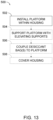
- a method 500 of installing a desiccant rack such as desiccant rack 100, as described above within a housing of an aerospace structure, such as housing 150 comprises: a step 502 of installing a platform, such as platform 110, of the desiccant rack, such as desiccant rack 100, within the housing such that first and second edge regions of the platform contact a nonplanar wall of the housing and the platform is suspended within the housing.
- step 502 further comprises orienting the platform within the housing such that a plane defined by the platform is substantially horizontal. Accordingly, the installed desiccant rack is suspended by the nonplanar wall such that the platform provides a horizontal surface from which bags containing a desiccant material may be suspended.
- a first edge region of the platform is defined by one or more first articulating contact structures, such as articulating contact structures 200, and a second edge region of the platform is defined by one or more second articulating contact structure, such as articulating contact structures 200.
- the platform further comprises a pivotable joint, such as pivotable joint 210, coupling each articulating contact structure to the platform. Accordingly, each articulating contact structure may be pivotable about the pivotable joint, adjusting each edge region of the platform.
- step 502 further comprises pivoting each of the first articulating contact structures and the second articulating contact structures about a respective pivotable joint, such that each articulating contact structure contacts the nonplanar wall.
- method 500 may be suitable for installing desiccant racks within housings having curved, angled, amorphous, or irregular shapes, as the first and second articulating contact structures facilitate an adjustable interface between the desiccant rack and the nonplanar wall.
- each articulating structure comprises a body (e.g., a tripod structure) comprising a central hub, at least three legs extending from the central hub, and a respective foot coupled to each leg.
- the body is coupled to the pivotable joint at the central hub. Accordingly, the body is pivotable with respect to the platform about the pivotable joint.
- each foot is coupled to a respective leg by a pivotable leg joint. Accordingly, each foot is pivotable with respect to the body about the pivotable leg joint.
- installing the platform within the housing comprises pivoting the articulating contact structures such that each foot of the articulating contact structure contacts the nonplanar wall.
- a method 500 of installing a desiccant rack also may include a step 504 of supporting the platform with elevating supports.
- the elevating supports are oriented substantially orthogonally to the platform.
- supporting the platform includes placing the elevating supports on the nonplanar wall such that a distal edge region of each elevating support contacts the nonplanar wall.
- the distal edge region of each elevating support is defined by one or more articulating contact structures, such as articulating contact structure 200.
- the elevating support further comprises a pivotable joint, such as pivotable joint 210, coupling each articulating contact structure to the platform.
- each articulating contact structure may be pivotable about the pivotable joint, adjusting the distal edge region of each elevating support.
- placing the elevating supports on the nonplanar wall includes adjusting (e.g., rotating, pivoting, etc.) the articulating contact structures such that each articulating contact structure contacts the nonplanar wall.
- each articulating structure comprises a body comprising a central hub, at least three legs extending from the central hub, and a respective foot coupled to each leg. Accordingly, the body is pivotable with respect to the elevating support about the pivotable joint.
- each foot is coupled to a respective leg by a pivotable leg joint.
- each foot is pivotable with respect to the body about the pivotable leg joint.
- supporting the platform with elevating supports comprises pivoting the articulating contact structures such that each foot of the body contacts the nonplanar wall.
- step 504 and step 502 of method 500 are performed substantially simultaneously, as the platform and the elevating supports are portions of a unitary structure.
- a method 500 of installing a desiccant rack may also include a step 506 of coupling one or more bags containing a desiccant material to the platform.
- the one or more bags are coupled to the platform such that a largest face of each bag is parallel to an opening defined by the housing.
- the one or more bags are coupled to the platform such that a largest face of each bag is orthogonal to an opening defined by a housing.
- a majority of a surface area of each bag is exposed to air within the housing, such that air is free to contact desiccant material within each bag.
- conventional dehydration systems obscure large portions of a surface area of each bag containing a desiccant material, resulting in underutilization of the desiccant material.
- the platform is substantially similar to platform 110, described above. Accordingly, in some examples, the platform comprises a pair of rails and a plurality of rungs extending between the pair of rails. In some examples, each rail of the pair of rails is configured to extend from the first edge region of the platform to the second edge region of the platform. In some examples, coupling the one or more bags containing a desiccant material to the platform comprises coupling a first corner of each bag to a first rung of the plurality of rungs and coupling a second corner of each bag to a second rung of the plurality of rungs, such that a largest face of each bag is parallel to an opening defined by the housing. In some examples, coupling the one or more bags containing a desiccant material to the platform comprises coupling each bag to a rail of the pair of rails.
- Coupling the one or more bags containing a desiccant material to the platform may comprise any suitable coupling method, such as tying, clipping, hooking, adhering, and/or the like.
- coupling the one or more bags containing a desiccant material to the platform comprises tying each bag to the platform using ties.
- the ties are integrated within the one or more bags, such that tying each bag to the platform includes tying ties extending from corners of the one or more bags to the platform.
- coupling the one or more bags containing a desiccant material to the platform comprises attaching each bag to the platform using one or more clips.
- a method 500 of installing a desiccant rack also may include a step 508 of covering the structure and/or the housing with a cover, such that the desiccant rack and bags of desiccant material are sealed within the housing.
- covering the structure and/or the housing with a cover comprises obscuring an opening of the housing.
- covering the structure and/or housing with a cover forms an airtight compartment containing the desiccant rack and the bags of desiccant material. As the bags of desiccant material are sealed within the compartment, air within the compartment is dehydrated by the bags of desiccant material.
- the terms “adapted” and “configured” mean that the element, component, or other subject matter is designed and/or intended to perform a given function. Thus, the use of the terms “adapted” and “configured” should not be construed to mean that a given element, component, or other subject matter is simply “capable of” performing a given function but that the element, component, and/or other subject matter is specifically selected, created, implemented, utilized, programmed, and/or designed for the purpose of performing the function. It is also within the scope of the present disclosure that elements, components, and/or other recited subject matter that is recited as being adapted to perform a particular function may additionally or alternatively be described as being configured to perform that function, and vice versa. Similarly, subject matter that is recited as being configured to perform a particular function may additionally or alternatively be described as being operative to perform that function.
- the term "and/or" placed between a first entity and a second entity means one of (1) the first entity, (2) the second entity, and (3) the first entity and the second entity.
- Multiple entries listed with “and/or” should be construed in the same manner, i.e., "one or more" of the entities so conjoined.
- Other entities optionally may be present other than the entities specifically identified by the "and/or” clause, whether related or unrelated to those entities specifically identified.
- a reference to "A and/or B,” when used in conjunction with open-ended language such as “comprising,” may refer, in one example, to A only (optionally including entities other than B); in another example, to B only (optionally including entities other than A); in yet another example, to both A and B (optionally including other entities).
- These entities may refer to elements, actions, structures, steps, operations, values, and the like.
Landscapes
- Engineering & Computer Science (AREA)
- Chemical & Material Sciences (AREA)
- Mechanical Engineering (AREA)
- Transportation (AREA)
- General Chemical & Material Sciences (AREA)
- Chemical Kinetics & Catalysis (AREA)
- Oil, Petroleum & Natural Gas (AREA)
- Analytical Chemistry (AREA)
- Manufacturing & Machinery (AREA)
- Aviation & Aerospace Engineering (AREA)
- General Engineering & Computer Science (AREA)
- Combustion & Propulsion (AREA)
- Food Science & Technology (AREA)
- Drying Of Gases (AREA)
Abstract
Description
- The present disclosure relates to engine desiccant racks, methods of installing the same, systems for preventing corrosion, and articulating contact structures.
- Aerospace structures, such as engine housings or cowlings, nacelles, rocket nozzles, and/or the like are susceptible to corrosion due to moisture build up within the structures. Accordingly, desiccant materials are commonly used to dehydrate aerospace structures during storage. The desiccant materials remove condensation and other moisture accumulated within the aerospace structure during use, such as during flight. Desiccant materials also may prevent condensation from accumulating within the aerospace structures during storage.
- Conventional systems for deploying desiccant materials typically include stacking bags containing desiccant materials in an opening of the aerospace structure (e.g., an engine inlet). Stacking bags containing desiccant materials in this manner results in underutilization of the desiccant material, as a large portion of the surface area of each bag is obscured, either by adjacent bags or by walls of the aerospace structure. These conventional systems typically result in desiccant utilization of less than 25%.
- Apparatuses and methods for suspending bags of desiccant material within housings of aerospace structures are disclosed. In some examples, an engine desiccant rack for suspending one or more bags of a desiccant material within a housing of an aerospace structure includes a platform comprising a first edge region and a second edge region opposite the first edge region. In some examples, the platform is configured to contact a first portion of a nonplanar wall of the housing at the first edge region and a second portion of the nonplanar wall of the housing at the second edge region, such that the platform is suspended by the nonplanar wall.
- In some examples, a system for preventing corrosion within a housing of a structure includes: a desiccant rack and one or more bags containing a desiccant material. In some examples, the desiccant rack is the engine desiccant rack described above. In some examples, each bag of the one or more bags containing a desiccant material is suspended from the platform such that a largest face of each bag is oriented parallel to a plane defined by an opening of the housing.
- In some examples, a method of installing a desiccant rack, such as the desiccant rack described above, within a housing of an aerospace structure includes: installing a platform of the desiccant rack within the housing. In some examples, installing the platform of the desiccant rack within the housing includes installing the platform such that first and second edge regions of the platform contact a nonplanar wall of the housing and the platform is suspended within the housing.
- In some examples, an articulating contact structure suitable for inclusion in desiccant racks described above includes: a body and a pivotable joint. In some examples, the body includes a central hub and at least three legs extending from the central hub. In some examples, the pivotable joint is coupled to the central hub opposite the at least three legs.
-
-
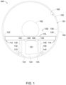
Fig. 1 is a schematic elevation view of an illustrative system for preventing corrosion according to the present disclosure, depicted as installed in a housing of an aerospace structure. The illustrative system for preventing corrosion includes an illustrative desiccant rack. -
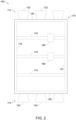
Fig. 2 is a schematic top plan view of the desiccant rack ofFig. 1 . -
Fig. 3 is an isometric view of an illustrative desiccant rack and engine housing according to the present disclosure. -
Fig. 4 is an isometric view of a first illustrative articulating contact structure suitable for inclusion in the desiccant racks ofFigs. 1-3 , depicted in an angled orientation. The first illustrative articulating contact structure comprises a body and a plurality of feet coupled to the body. -
Fig. 5 is an isometric view of a first illustrative body suitable for use in the first illustrative articulating contact structure ofFig. 4 , depicted in a vertical orientation. -
Fig. 6 is a top plan view of the first illustrative body ofFig. 5 . -
Fig. 7 is a side elevation view of the first illustrative body ofFig. 5 . -
Fig. 8 is a front elevation view of the first illustrative body ofFig. 5 . -
Fig. 9 is a bottom plan view of the first illustrative body ofFig. 5 . -
Fig. 10 is an isometric view of a first illustrative foot suitable for use in the first illustrative articulating contact structure ofFig. 4 , depicted in a vertical orientation. -
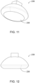
Fig. 11 is an isometric view of the first illustrative foot ofFig. 10 , depicted in an angled orientation. -
Fig. 12 is a front elevation view of the first illustrative foot ofFig. 10 . -
Fig. 13 is a flow chart schematically representing steps of an illustrative method for installing a system for preventing corrosion within a housing of an aerospace structure. - Apparatuses and methods for suspending bags of desiccant material within housings of aerospace structures are disclosed. Generally, in the figures, elements that are likely to be included in a given example are illustrated in solid lines, while elements that are optional to a given example are illustrated in broken lines. However, elements that are illustrated in solid lines are not essential to all examples of the present disclosure, and an element shown in solid lines may be omitted from a particular example without departing from the scope of the present disclosure.
- As schematically illustrated in
Figs. 1 and2 , adesiccant rack 100 in accordance with the present teachings includes at least aplatform 110 comprising afirst edge region 112 and asecond edge region 114 opposite the first edge region.Platform 110 is configured to contact a first portion of anonplanar wall 154 of a housing of an aerospace structure atfirst edge region 112 and to contact a second portion ofnonplanar wall 154 atsecond edge region 114, such thatplatform 110 is suspended bynonplanar wall 154. Desiccantrack 100 is configured such that one ormore bags 120 of a desiccant material (AKA desiccant bags) may be suspended from the desiccant rack withinhousing 150, such that utilization of desiccant material withinbags 120 is maximized. Accordingly, in some examples,platform 110 ofdesiccant rack 100 is configured to suspend one ormore bags 120 of a desiccant material such that alargest face 121 of eachbag 120 is oriented parallel to a plane defined by an opening 156 ofhousing 150. In some examples,platform 110 is configured to suspend one ormore bags 120 of a desiccant material such that alargest face 121 of eachbag 120 is oriented parallel to a face of anengine 152 received byhousing 150. -
Desiccant rack 100 may be configured to suspendbags 120 of desiccant material within anysuitable housing 150 of any suitable aerospace structure. Accordingly, whilehousing 150 is depicted inFig. 1 as having a substantially cylindrical shape,desiccant rack 100 is configured to interface with housings having any suitable shape and/or size, such as cylindrical, conical, frustoconical, oblong, amorphous, irregular, and/or the like. Similarly, whilehousing 150 is depicted as having a substantially circular cross-section,desiccant rack 100 is configured to interface with housings having any suitable cross-section, such as circular, oval, stadium-shaped, oblong, irregular, amorphous, and/or the like. However, asplatform 110 is configured to be suspended bynonplanar wall 154,suitable housings 150 generally include angled and/or curved walls, which may interface withfirst edge region 112 andsecond edge region 114 ofplatform 110. Accordingly, in some examples,housing 150 comprises an engine cowling. In some examples,housing 150 comprises anacelle 158 defining a cylindrical opening 156receiving platform 110. - As
bags 120 are suspended fromplatform 110 such that alargest face 121 of each bag is parallel to a plane defined by opening 156, air entering the housing through opening 156 contacts and/or passes through the bags, dehydrating the air. Similarly, stagnant air contained within the housing is dehydrated by the bags containing desiccant material. Furthermore, as a majority (e.g., greater than 50%, greater than 60%, greater than 75%, greater than 80%, greater than 90%, etc.) of a total surface area of each bag is exposed to air within the housing, moisture within the housing is absorbed by the bags containing desiccant material more quickly than when compared with existing systems and methods for dehydrating housings of aerospace structures. -
Platform 110 may have any suitable shape and/or size configured to support bags containing a desiccant material, such as planar, curved, angled, irregular, and/or the like. In some examples, as schematically illustrated in dashed lines inFig. 2 ,platform 110 comprises a pair ofrails 116 and a plurality ofrungs 118 extending between pair ofrails 116. In some examples, each rail of the pair of rails is configured to extend fromfirst edge region 112 ofplatform 110 tosecond edge region 114 ofplatform 110, forming a substantially ladder-shaped structure. In some examples,first edge region 112 ofplatform 110 comprises afirst rung 126 of plurality ofrungs 118 andsecond edge region 114 ofplatform 110 comprises asecond rung 128 of plurality ofrungs 118. Accordingly, in these examples,platform 110 comprises a planar structure having a substantially rectangular silhouette. In some examples,platform 110 is configured to be oriented substantially horizontally when installed withinhousing 150. In some examples,platform 110 comprises a unitary plane of material. - In some examples, as also illustrated schematically in dashed lines in
Figs. 1 and2 ,platform 110 further comprises acoupling mechanism 168 configured to couple eachbag 120 to desiccantrack 100.Coupling mechanism 168 may comprise any suitable structure configured to couple a bag to desiccantrack 100, such as clips, hooks, tabs, and/or the like. In some examples, as depicted inFig. 2 ,coupling mechanism 168 is coupled torungs 118 ofplatform 110. However,coupling mechanism 168 may be coupled to any suitable portion ofplatform 110, such asrails 116,rungs 118,edge regions - In some examples, as illustrated schematically in
Figs. 1 and2 ,first edge region 112 andsecond edge region 114 ofplatform 110 are respectively defined by at least one articulating contact structure configured to interface withnonplanar wall 154. Accordingly, in some examples,first edge region 112 is defined by at least a first articulatingcontact structure 122 coupled tofirst rung 126, andsecond edge region 114 is defined by at least a second articulatingcontact structure 124 coupled tosecond rung 128. Articulatingcontact structures nonplanar wall 154, such that contact betweendesiccant rack 100 and the wall is maximized. Accordingly, articulatingcontact structures nonplanar wall 154. In some examples, articulatingcontact structures contact structure 200, described below with respect toFigs. 4-12 . In some examples, articulatingcontact structures first edge region 112 is defined by a first plurality of articulatingcontact structures 122 spaced alongfirst rung 126 andsecond edge region 114 is defined by a second plurality of articulatingcontact structures 124 spaced alongsecond rung 128. - In some examples, as illustrated schematically in
Fig. 1 ,desiccant rack 100 further comprises a first elevatingsupport 130 extending substantially orthogonally fromplatform 110. Extending substantially orthogonally comprises extending within 15 degrees of orthogonal. First elevatingsupport 130 comprises athird edge region 132 disposed at adistal end 133 of the first elevating support, such thatthird edge region 132 is configured to contact a third portion ofnonplanar wall 154. In some examples, first elevatingsupport 130 is configured to be oriented substantially vertically whendesiccant rack 100 is installed within a housing, such ashousing 150. First elevatingsupport 130 is configured to supportplatform 110, such thatplatform 110 is supported both by contact withnonplanar wall 154 at first andsecond edge region support 130. In some examples,third edge region 132 is defined by at least a third articulatingcontact structure 134. As described above, articulatingcontact structure 134 is configured to interface with nonplanar surfaces, such asnonplanar wall 154, such that contact betweendesiccant rack 100 and the wall is maximized. Accordingly, articulatingcontact structure 134 may pivot, rotate, adjust, and/or the like, adapting the third edge region tononplanar wall 154. In some examples, articulatingcontact structure 134 is substantially identical to articulatingcontact structure 200, described below with respect toFigs. 4-12 . In some examples, articulatingcontact structure 134 comprises a roller, suction cup, cushion, finger, and/or the like. In some examples,third edge region 132 is defined by a third plurality of articulatingcontact structures 134 spaced alongdistal end 133 of first elevatingsupport 130. In some examples, first elevatingsupport 130 comprises a single rung definingdistal end 133 and a pair of rails extending substantially orthogonally fromplatform 110. In some examples, first elevatingsupport 130 comprises a unitary plane of material extending orthogonally fromplatform 110 and terminating atdistal end 133. - In some examples, as illustrated schematically in
Fig. 1 ,desiccant rack 100 further comprises a second elevatingsupport 140 extending substantially orthogonally fromplatform 110. Extending substantially orthogonally may comprise extending at any suitable angle within a selected deviation from 90 degrees, such as within 5 degrees, within 10 degrees, within 15 degrees, and/or the like. Second elevatingsupport 140 comprises afourth edge region 142 disposed at adistal end 143 of the second elevating support, such thatfourth edge region 142 of second elevatingsupport 140 contacts a fourth portion ofnonplanar wall 154. In some examples, second elevatingsupport 140 is configured to be oriented substantially vertically whendesiccant rack 100 is installed within a housing, such ashousing 150. Second elevatingsupport 140 is configured to supportplatform 110, such thatplatform 110 is supported both by contact withnonplanar wall 154 and by elevatingsupports support 130 and second elevatingsupport 140 extend substantially orthogonally fromplatform 110, extending substantially orthogonally may comprise any suitable angle which provides support toplatform 110 from below, such as between 60 degrees and 120 degrees, between 75 degrees and 105, degrees, between 80 degrees and 110 degrees, and/or the like. In some examples, first elevatingsupport 130 and second elevatingsupport 140 extend away from each other such that the platform, first elevating support, and second elevating support form a substantially trapezoidal shape when viewed from the angle depicted inFig. 1 . In some examples, first elevatingsupport 130 and second elevatingsupport 140 are substantially parallel and extend fromplatform 110 at right angles. In some examples, second elevatingsupport 140 comprises a single rung definingdistal end 143 and a pair of rails extending substantially orthogonally fromplatform 110. In some examples, second elevatingsupport 140 comprises a unitary plane of material extending orthogonally fromplatform 110 and terminating atdistal end 143. - In some examples,
fourth edge region 142 is defined by at least a fourth articulatingcontact structure 144. As described above, articulatingcontact structure 144 is configured to interface with nonplanar surfaces, such asnonplanar wall 154, such that contact betweendesiccant rack 100 and the wall is maximized. Accordingly, articulatingcontact structure 144 may pivot, rotate, adjust, and/or the like, adapting the fourth edge region tononplanar wall 154. In some examples, articulatingcontact structures 144 is substantially identical to articulatingcontact structure 200, described below with respect toFigs. 4-12 . In some examples, articulatingcontact structure 144 comprises a roller, suction cup, cushion, finger, and/or the like. In some examples,fourth edge region 142 is defined by a fourth plurality of articulatingcontact structures 144 spaced alongdistal end 143 of second elevatingsupport 140. - Desiccant racks in accordance with the present teachings may comprise any suitable materials, such as metals (e.g., aluminum, steel, etc.), composites (e.g., carbon fiber, etc.), polymers (e.g., PVC (polyvinylidene chloride), PET (polyethylene terephthalate), etc.), and/or the like.
- As schematically illustrated in
Fig. 1 and2 ,system 300 for preventing corrosion within ahousing 150 of a structure in accordance with the present teachings includes atleast desiccant rack 100 and one ormore bags 120 containing a desiccant material, where eachbag 120 is suspended fromplatform 110 ofdesiccant rack 100, such that a majority of a surface area of each bag is exposed to air within the housing. In some examples, a majority of a surface area of each bag comprises (e.g., greater than 50% of a surface area of the bag, greater than 60% of a surface area of the bag, greater than 75% of a surface area of the bag, greater than 80% of a surface area of the bag, greater than 90% of a surface area of the bag is exposed to air within the housing. In other words, in some examples, the bags are suspended in such a way that the bags do not contact each other. In some examples, eachbag 120 is suspended such that alargest face 121 of each bag is oriented parallel to aplane 151 defined by an opening of the housing. In some examples, eachbag 120 is suspended such that alargest face 121 of each bag is oriented orthogonal to aplane 151 defined by an opening of the housing. -
Bags 120 may contain any suitable desiccant material for dehydrating aerospace structures, such as silica gel, bentonite clay, montmorillonite clay, calcium chloride, and/or the like. Generally,bags 120 included withinsystem 300 comprise a breathable, flexible material, such as fabric, porous polymer, and/or the like which facilitates the permeability of the bag to air. Accordingly, moisture within air contained withinhousing 150 is dehydrated as the air passes throughbags 120 and contacts the desiccant material contained therein. - In some examples,
bags 120 further comprise one or more ties forming acoupling mechanism 168, the ties extending from respective corners of the bag. Accordingly,bags 120 may be coupled toplatform 110 ofdesiccant rack 100 by tying each tie around a portion ofplatform 110. In examples whereplatform 110 comprises a pair ofrails 116 and a plurality ofrungs 118 extending between the pair of rails,bags 120 may be coupled toplatform 110 by tying afirst corner 162 of abag 120 to a first rung of the plurality of rungs and by tying asecond corner 164 of abag 120 to a second rung of the plurality of rungs, suspending the one or more bags between a pair of rungs of the plurality of rungs. In some examples,bags 120 may be coupled toplatform 110 by tying afirst corner 162 of abag 120 to a first rail of the pair ofrails 116 and by tying asecond corner 164 of the bag to a second rail of the pair of rails, suspending the one or more bags from a rail of the pair of rails. - In some examples, as described above,
desiccant rack 100 further comprises acoupling mechanism 168 configured to couplebags 120 toplatform 110.Coupling mechanism 168 may comprise any suitable structure configured to couple a bag todesiccant rack 100, such as clips, hooks, tabs, and/or the like. In some examples,coupling mechanism 168 comprises one or more clips, such that each bag may be coupled to the platform by the one or more clips. - In some examples,
system 300 further comprises acover 160 configured to obscure the opening of the housing, such thatdesiccant rack 100 andbags 120 of desiccant material are sealed within a compartment defined bycover 160 andhousing 150 when the cover is installed. Cover 160 may comprise any suitable airtight material, such as coated fabric, metal, plastics, and/or the like. Accordingly, whenhousing 150 is covered bycover 160,bags 120 of desiccant material are sealed within the compartment along with any moisture accumulated within the housing during use of the aerospace structure, such as during flight.Bags 120 of desiccant material also prevent the accumulation of moisture within the housing during storage. Moisture is removed from the air as the moisture contacts the desiccant material and is absorbed by the desiccant material. Accordingly, asdesiccant rack 100 suspendsbags 120 such that a large portion of the surface area of the bags is exposed, desiccant material within the bags is utilized at a higher rate when compared with conventional methods. - Turning now to
Fig. 3 , an illustrative non-exclusive example of desiccant racks in accordance with the present teachings, such asdesiccant rack 100 is illustrated. Where appropriate, the reference numerals from the schematic illustrations ofFigs. 1-2 are used to designate corresponding parts of the examples ofFig. 3 ; however, the example ofFig. 3 is non-exclusive and does not limitdesiccant racks 100 to the illustrated embodiments ofFig. 3 . That is, desiccant racks 100 are not limited to the specific embodiments ofFig. 3 , anddesiccant racks 100 may incorporate any number of the various aspects, configurations, characteristics, properties, etc. ofdesiccant racks 100 that are illustrated in and discussed with reference to the schematic representations ofFigs. 1-2 and/or the embodiment ofFig. 3 , as well as variations thereof, without requiring the inclusion of all such aspects, configurations, characteristics, properties, etc. For the purpose of brevity, each previously discussed component, part, portion, aspect, region, etc. or variants thereof may not be discussed, illustrated, and/or labeled again with respect to the examples ofFig. 3 ; however, it is within the scope of the present disclosure that the previously discussed features, variants, etc. may be utilized with the example ofFig. 3 . - As seen in
Fig. 3 , desiccant rack 100' is an example of adesiccant rack 100 including aplatform 110 and first and second elevatingsupports Platform 110 comprises a pair ofrails 116 and a plurality ofrungs 118 extending between pair ofrails 116. Each rail of the pair of rails is configured to extend fromfirst edge region 112 ofplatform 110 tosecond edge region 114 ofplatform 110, forming a substantially ladder-shaped structure. In the example depicted inFig. 3 ,first edge region 112 ofplatform 110 comprises afirst rung 126 of plurality ofrungs 118 andsecond edge region 114 ofplatform 110 comprises asecond rung 128 of plurality ofrungs 118.First edge region 112 andsecond edge region 114 ofplatform 110 are respectively defined by at least one articulating contact structure configured to interface withnonplanar wall 154. Accordingly, in some examples,first edge region 112 is defined by at least a first articulatingcontact structure 122 coupled to first rung 125, andsecond edge region 114 is defined by at least a second articulatingcontact structure 124 coupled tosecond rung 128. - Desiccant rack 100' further comprises first elevating
support 130 and second elevatingsupport 140, which extend orthogonally fromplatform 110. First elevatingsupport 130 comprises athird edge region 132 disposed at adistal end 133 of the first elevating support, such thatthird edge region 132 is configured to contact a third portion ofnonplanar wall 154.Third edge region 132 is defined by at least a third articulatingcontact structure 134. Second elevatingsupport 140 comprises afourth edge region 142 disposed at adistal end 143 of the second elevating support, such thatfourth edge region 142 of second elevatingsupport 140 contacts a fourth portion ofnonplanar wall 154. First elevatingsupport 130 and second elevatingsupport 140 is configured to supportplatform 110, such thatplatform 110 is supported both by contact withnonplanar wall 154 and by elevatingsupports Fourth edge region 142 is defined by at least a fourth articulatingcontact structure 144. -
Fig. 3 depicts desiccant rack 100' as received by anacelle 158 of an aircraft structure.Nacelle 158 is an example of asuitable housing 150 in which desiccant racks, such asdesiccant rack 100 and desiccant rack 100' may be installed.Nacelle 158 defines anopening 156 in which desiccant rack 100' is installed.Nacelle 158 contains anengine 152. Accordingly, desiccant rack 100', as installed innacelle 158, is configured to prevent corrosion withinengine 152. - Turning now to
Figs. 4-12 , an illustrative non-exclusive example of articulating contact structures in accordance with the present teachings, such as articulatingcontact structures Figs. 4-12 is non-exclusive and does not limit articulatingcontact structures Figs. 4-12 . That is, articulatingcontact structures contact structures contact structures Figs. 1-2 and/or the embodiments ofFigs. 4-12 , as well as variations thereof, without requiring the inclusion of all such aspects, configurations, characteristics, properties, etc. - As seen in
Figs. 4-12 , an articulatingcontact structure 200 is depicted and described. Articulatingcontact structure 200 is an example of an articulatingcontact structure desiccant rack 100 and systems such assystem 300.Fig. 4 depicts articulatingcontact structure 200 in an assembled configuration, withfeet 230 coupled tobody 220.Figs. 4-9 depictbody 220, depicted withoutfeet 230.Figs. 10-12 depictfeet 230. - Articulating
contact structure 200 comprises abody 220 comprising acentral hub 222 and at least threelegs 224 extending from the central hub.Body 220 may be interchangeably referred to as a tripod structure, but articulating contact structures in accordance with the present teachings may comprise any suitable number of legs, such as three, four, five, and/or the like. Articulatingcontact structure 200 further comprises a pivotable joint 210 coupled tocentral hub 222opposite legs 224. In the example depicted inFigs. 4-12 , pivotable joint 210 comprises a ball-and-socket joint. However, other suitable joints may be envisaged, such as a ball joint, a revolute joint, and/or the like. As pivotable joint 210 comprises a ball-and-socket joint,body 220 may be freely rotated about the pivotable joint (i.e., has three degrees of freedom). In the example depicted inFigs. 4-12 ,central hub 222 ofbody 220 comprises asocket 214 of pivotable joint 210. Accordingly,ball 212 is configured to be coupled toplatform 110 ofdesiccant rack 100. As described above,ball 212 may be coupled to arung 118 such that articulatingcontact structure 200 forms an edge region of the platform. However, in another example,central hub 222 ofbody 220 comprises a ball of pivotable joint 210, and a socket of the pivotable joint is configured to be coupled toplatform 110 ofdesiccant rack 100. - In the example depicted in
Figs. 4-9 ,body 220 comprises threelegs 224 extending from acentral hub 222. However, bodies in accordance with the present teachings may comprise any suitable number oflegs 224 extending fromcentral hub 222, such as three, four, five, and/or the like.Legs 224 extend fromcentral hub 222 in a direction opposite pivotable joint 210.Body 220 comprises a plurality ofstruts 232 extending between each pair oflegs 224, which reinforce and support the body. However, an articulating contact structure omitting struts 232 could be envisaged. - As depicted in
Fig. 4 , eachleg 224 ofbody 220 further comprises arespective foot 230 and a respective pivotable leg joint 226. Eachfoot 230 is coupled toleg 224 by a pivotable leg joint 226. In some examples, pivotable leg joint 226 is a ball-and-socket joint. Accordingly, eachfoot 230 may be freely rotated about leg 224 (i.e., has three degrees of freedom). However, other suitable joints may be envisaged, such as a ball joint, a revolute joint, and/or the like. In examples where pivotable leg joint 226 is a revolute joint, articulatingcontact structure 200 is freely pivotable about pivotable joint 210, and each respective pivotable leg joint 226 has a single degree of freedom. In the example depicted inFigs. 4-12 , eachleg 224 is coupled to aball 234 of pivotable leg joint 226, andfoot 230 is coupled tosocket 236 of the pivotable leg joint. However, in some examples, eachleg 224 is coupled to a socket of the pivotable leg joint, and each foot is coupled to a ball of the pivotable leg joint. - In the example depicted in
Fig. 4 , afoot 230 is coupled tosocket 236 by apost 240 and ahole 242 mated in an interference fit. However,foot 230 may be coupled tobody 220 by any suitable coupling mechanism, such as an interference fit, bolts, pins, screws, and/or the like. In some examples, eachfoot 230 is permanently coupled tobody 220. In some examples,foot 230 is substantially semispherical. As depicted inFigs. 10-12 ,foot 230 has a substantially semispherical body and acontact surface 238 configured to contactnonplanar wall 154. In some examples,contact surface 238 is substantially planar. In some examples,contact surface 238 is rounded and/or contoured to mimic a contour of nonplanar wall 54. - In some examples, each
foot 230 of articulatingcontact structure 200 is configured to contactnonplanar wall 154 when in use, such that each articulating contact structure has a number of points of contact with the nonplanar wall equal to the number of legs extending fromcentral hub 222. In the example depicted inFigs. 4-12 , articulatingcontact structure 200 has threelegs 224 and three points of contact with the nonplanar wall. As eachbody 220 may be rotated about pivotable joint 210 and eachfoot 230 may be rotated about a respective pivotable leg joint 226, each articulating contact structure is adjustable. Each edge region of a desiccant rack including articulating contact structures such as articulatingcontact structure 200 is configured to conform to a nonplanar surface having any suitable shape. Articulating contact structures such as articulatingcontact structure 200 may facilitate increased contact between linear edge regions (e.g.,edge regions nonplanar wall 154. -
Feet 230 may comprise any material suitable for providing a contact surface with a housing of an aircraft structure. In some examples,feet 230 comprise materials configured to provide a smooth contact surface, such as aluminum, steel, PVC (polyvinylidene chloride), PET (polyethylene terephthalate), and/or the like. In some examples,feet 230 comprise resilient materials configured to provide a cushioned and/or adhesive contact surface, such as rubber, thermoplastic elastomers, and/or the like. -
Fig. 13 schematically provides a flowchart that represents illustrative, non-exclusive examples of methods according to the present disclosure. InFig. 13 , some steps are illustrated in dashed boxes indicating that such steps may be optional or may correspond to an optional version of a method according to the present disclosure. That said, not all methods according to the present disclosure are required to include the steps illustrated in solid boxes. The methods and steps illustrated inFig. 13 are not limiting and other methods and steps are within the scope of the present disclosure, including methods having greater than or fewer than the number of steps illustrated, as understood from the discussions herein. - As seen in
Fig. 13 , amethod 500 of installing a desiccant rack such asdesiccant rack 100, as described above within a housing of an aerospace structure, such ashousing 150 comprises: astep 502 of installing a platform, such asplatform 110, of the desiccant rack, such asdesiccant rack 100, within the housing such that first and second edge regions of the platform contact a nonplanar wall of the housing and the platform is suspended within the housing. In some examples, step 502 further comprises orienting the platform within the housing such that a plane defined by the platform is substantially horizontal. Accordingly, the installed desiccant rack is suspended by the nonplanar wall such that the platform provides a horizontal surface from which bags containing a desiccant material may be suspended. In some examples, a first edge region of the platform is defined by one or more first articulating contact structures, such as articulatingcontact structures 200, and a second edge region of the platform is defined by one or more second articulating contact structure, such as articulatingcontact structures 200. In some examples, the platform further comprises a pivotable joint, such as pivotable joint 210, coupling each articulating contact structure to the platform. Accordingly, each articulating contact structure may be pivotable about the pivotable joint, adjusting each edge region of the platform. - In some examples, step 502 further comprises pivoting each of the first articulating contact structures and the second articulating contact structures about a respective pivotable joint, such that each articulating contact structure contacts the nonplanar wall. Accordingly,
method 500 may be suitable for installing desiccant racks within housings having curved, angled, amorphous, or irregular shapes, as the first and second articulating contact structures facilitate an adjustable interface between the desiccant rack and the nonplanar wall. In some examples, such as when the first and second articulating contact structures are substantially similar to articulatingcontact structures 200, each articulating structure comprises a body (e.g., a tripod structure) comprising a central hub, at least three legs extending from the central hub, and a respective foot coupled to each leg. In some examples, the body is coupled to the pivotable joint at the central hub. Accordingly, the body is pivotable with respect to the platform about the pivotable joint. In some examples, each foot is coupled to a respective leg by a pivotable leg joint. Accordingly, each foot is pivotable with respect to the body about the pivotable leg joint. In these examples, installing the platform within the housing comprises pivoting the articulating contact structures such that each foot of the articulating contact structure contacts the nonplanar wall. - As schematically illustrated in dashed lines in
Fig. 13 , amethod 500 of installing a desiccant rack also may include astep 504 of supporting the platform with elevating supports. In some examples, the elevating supports are oriented substantially orthogonally to the platform. In some examples, supporting the platform includes placing the elevating supports on the nonplanar wall such that a distal edge region of each elevating support contacts the nonplanar wall. In some examples, the distal edge region of each elevating support is defined by one or more articulating contact structures, such as articulatingcontact structure 200. In some examples, the elevating support further comprises a pivotable joint, such as pivotable joint 210, coupling each articulating contact structure to the platform. Accordingly, each articulating contact structure may be pivotable about the pivotable joint, adjusting the distal edge region of each elevating support. In these examples, placing the elevating supports on the nonplanar wall includes adjusting (e.g., rotating, pivoting, etc.) the articulating contact structures such that each articulating contact structure contacts the nonplanar wall. In some examples, such as when the first and second articulating contact structures are substantially similar to articulatingcontact structures 200, each articulating structure comprises a body comprising a central hub, at least three legs extending from the central hub, and a respective foot coupled to each leg. Accordingly, the body is pivotable with respect to the elevating support about the pivotable joint. In some examples, each foot is coupled to a respective leg by a pivotable leg joint. Accordingly, each foot is pivotable with respect to the body about the pivotable leg joint. In these examples, supporting the platform with elevating supports comprises pivoting the articulating contact structures such that each foot of the body contacts the nonplanar wall. In some examples,step 504 and step 502 ofmethod 500 are performed substantially simultaneously, as the platform and the elevating supports are portions of a unitary structure. - As schematically illustrated in dashed lines in
Fig. 13 , amethod 500 of installing a desiccant rack may also include astep 506 of coupling one or more bags containing a desiccant material to the platform. In some examples, the one or more bags are coupled to the platform such that a largest face of each bag is parallel to an opening defined by the housing. In some examples, the one or more bags are coupled to the platform such that a largest face of each bag is orthogonal to an opening defined by a housing. In either example, a majority of a surface area of each bag is exposed to air within the housing, such that air is free to contact desiccant material within each bag. In contrast, conventional dehydration systems obscure large portions of a surface area of each bag containing a desiccant material, resulting in underutilization of the desiccant material. - In some examples, the platform is substantially similar to
platform 110, described above. Accordingly, in some examples, the platform comprises a pair of rails and a plurality of rungs extending between the pair of rails. In some examples, each rail of the pair of rails is configured to extend from the first edge region of the platform to the second edge region of the platform. In some examples, coupling the one or more bags containing a desiccant material to the platform comprises coupling a first corner of each bag to a first rung of the plurality of rungs and coupling a second corner of each bag to a second rung of the plurality of rungs, such that a largest face of each bag is parallel to an opening defined by the housing. In some examples, coupling the one or more bags containing a desiccant material to the platform comprises coupling each bag to a rail of the pair of rails. - Coupling the one or more bags containing a desiccant material to the platform may comprise any suitable coupling method, such as tying, clipping, hooking, adhering, and/or the like. In some examples, coupling the one or more bags containing a desiccant material to the platform comprises tying each bag to the platform using ties. In some examples, the ties are integrated within the one or more bags, such that tying each bag to the platform includes tying ties extending from corners of the one or more bags to the platform. In some examples, coupling the one or more bags containing a desiccant material to the platform comprises attaching each bag to the platform using one or more clips.
- As schematically illustrated in dashed lines in
Fig. 13 , amethod 500 of installing a desiccant rack also may include astep 508 of covering the structure and/or the housing with a cover, such that the desiccant rack and bags of desiccant material are sealed within the housing. In some examples, covering the structure and/or the housing with a cover comprises obscuring an opening of the housing. In some examples, covering the structure and/or housing with a cover forms an airtight compartment containing the desiccant rack and the bags of desiccant material. As the bags of desiccant material are sealed within the compartment, air within the compartment is dehydrated by the bags of desiccant material. - Illustrative, non-exclusive examples of inventive subject matter according to the present disclosure are described in the following enumerated paragraphs:
- A0. A desiccant rack (100) for suspending one or more bags (120) of a desiccant material within a housing (150) of an aerospace structure, the desiccant rack comprising:
a platform (110) comprising a first edge region (112) and a second edge region (114) opposite the first edge region, wherein the platform (110) is configured to contact a first portion of a nonplanar wall (154) of the housing (150) at the first edge region (112) and a second portion of the nonplanar wall (154) of the housing (150) at the second edge region (114), such that the platform (110) is suspended by the nonplanar wall (154). - A1. The desiccant rack of paragraph A0, wherein the platform (110) is configured to suspend one or more bags (120) of a desiccant material such that a largest face (121) of each bag (120) is oriented parallel to a plane defined by an opening (156) of the housing (150).
- A1.1. The desiccant rack (100) of paragraph A1, wherein the platform (110) is configured to suspend one or more bags (120) of a desiccant material such that a largest face (121) of each bag (120) is oriented parallel to a face of an engine (152) received by the housing (150).
- A2. The desiccant rack (100) of paragraph A1, wherein the platform (110) is configured to suspend one or more bags (120) of a desiccant material such that a largest face (121) of each bag (120) is oriented parallel to a face of an engine (152) received by the housing (150).
- A3. The desiccant rack (100) of any of paragraphs A0 through A2, wherein the housing (150) comprises an engine cowling.
- A4. The desiccant rack (100) of any of paragraphs A0 through A2, wherein the housing (150) comprises a nacelle (158) defining a cylindrical opening (156) receiving the platform (110).
- A5. The desiccant rack (100) of any of paragraphs A0 through A4, wherein the platform (110) comprises a pair of rails (116) and a plurality of rungs (118) extending between the pair of rails (116), wherein each rail of the pair of rails (116) is configured to extend from the first edge region (112) of the platform (110) to the second edge region (114) of the platform (110).
- A5.1. The desiccant rack (100) of paragraph A5, wherein the first edge region (112) of the platform (110) comprises a first rung (126) of the plurality of rungs (118) and wherein the second edge region (114) of the platform (110) comprises a second rung (128) of the plurality of rungs (118).
- A5.1.1. The desiccant rack (100) of any of paragraphs A5 through A5.1.2, further comprising a coupling mechanism (168) configured to couple each bag (120) to the desiccant rack (100).
- A5.1.2. The desiccant rack (100) of paragraph A5.1.1, wherein the coupling mechanism (168) comprises one or more clips.
- A6. The desiccant rack (100) of any of paragraphs A0 through A5.1.2, wherein the platform (110) is configured to be oriented substantially horizontally when installed within the housing (150).
- A7. The desiccant rack (100) of any of paragraphs A0 through A6, wherein the first edge region (112) is defined by at least a first articulating contact structure (122) coupled to the first rung (126), and wherein the second edge region (114) is defined by at least a second articulating contact structure (124) coupled to the second rung (128).
- A7.1. The desiccant rack (100) of paragraph A7, further comprising a pivotable joint (210) coupling each articulating contact structure (122/124) to a respective rung (126/128) of the desiccant rack (100).
- A7.1.1. The desiccant rack (100) of paragraph A7.1, wherein the pivotable joint (210) is a ball-and-socket joint.
- A7.2. The desiccant rack (100) of paragraph A7.1 or A7.1.1, wherein each articulating contact structure (200) comprises a body (220) comprising a central hub (222) and at least three legs (224) extending from the central hub (222).
- A7.2.1. The desiccant rack (100) of paragraph A7.2, wherein the body (220) is coupled to the pivotable joint (210) at the central hub (222).
- A7.2.2. The desiccant rack (100) of paragraph A7.2.1, wherein the at least three legs (224) extend from the central hub (222) in a direction opposite the pivotable joint (210).
- A7.2.3. The desiccant rack (100) of any of paragraphs A7.2 through A7.2.2, wherein the central hub (222) comprises a socket (214) of a/the ball-and-socket joint.
- A7.2.4. The desiccant rack (100) of any of paragraphs A7.2 through A7.2.3, wherein each leg (224) further comprises a respective foot (230) and a respective pivotable leg joint (226), wherein the foot (230) is coupled to the leg (224) of the body (220) by the pivotable leg joint (226).
- A7.2.5. The desiccant rack (100) of paragraph A7.2.4, wherein each foot (230) is substantially semispherical.
- A7.2.6. The desiccant rack (100) of any of paragraphs A7.2 through A7.2.5, wherein each foot (230) is configured to contact the nonplanar wall (154) when the desiccant rack (100) is installed within the housing (150), such that each articulating contact structure (200) has at least three points of contact with the nonplanar wall (154) .
- A7.3. The desiccant rack (100) of any of paragraphs A7 through A7.2.4, wherein the first edge region (112) is defined by a first plurality of articulating contact structures (122) spaced along the first rung (126), and wherein the second edge region (114) is defined by a second plurality of articulating contact structures (124/200) spaced along the second rung (128).
- A8. The desiccant rack (100) of any of paragraphs A0 through A7.3, further comprising a first elevating support (130) extending substantially orthogonally from the platform (110), the first elevating support further comprising a third edge region (132) disposed at a distal end (133) of the first elevating support (130), such that the third edge region (132) of the first elevating support (130) contacts a third portion of the nonplanar wall (154).
- A8.1. The desiccant rack (100) of paragraph A8, wherein the first elevating support (130) is oriented substantially vertically when the desiccant rack (100) is installed within the housing (150).
- A8.1.1. The desiccant rack (100) of paragraph A8 or A8.1, wherein the third edge region (132) is defined by at least a third articulating contact structure (134).
- A8.1.2. The desiccant rack (100) of paragraph A8.1.1, further comprising a pivotable joint (210) coupling the third articulating contact structure (134) to the distal end (133) of the first elevating support (130).
- A8.1.3. The desiccant rack (100) of paragraph A8.1.2, wherein the pivotable joint (210) is a ball-and-socket joint.
- A8.2. The desiccant rack (100) of any of paragraphs A8.1.1 through A8.1.3, wherein the third articulating contact structure (134) comprises a body (220) comprising a central hub (222) and at least three legs (224) extending from the central hub (222).
- A8.2.1. The desiccant rack (100) of paragraph A8.2, wherein the body (220) is coupled to the pivotable joint (210) at the central hub (222).
- A8.2.2. The desiccant rack (100) of paragraph A8.2.1, wherein the at least three legs (224) extend from the central hub (222) in a direction opposite the pivotable joint (210).
- A8.2.3. The desiccant rack (100) of any of paragraphs A8.2 through A8.2.2, wherein the central hub (222) comprises a socket (214) of a/the ball-and-socket joint.
- A8.2.4. The desiccant rack (100) of paragraph any of paragraphs A8.2 through A8.2.3, wherein each leg (224) further comprises a respective foot (230) and a respective pivotable leg joint (226), wherein the foot (230) is coupled to the leg (224) of the body (220) by the pivotable leg joint (226).
- A8.2.5. The desiccant rack (100) of paragraph A8.2.4, wherein each foot (230) is substantially semispherical.
- A8.2.6. The desiccant rack (100) of any of paragraphs A8.2 through A8.2.5, wherein each foot (230) is configured to contact the nonplanar wall (154) when the desiccant rack (100) is installed within the housing (150), such that each articulating contact structure (200) has at least three points of contact with the nonplanar wall (154).
- A8.3. The desiccant rack (100) of any of paragraphs A8.1.1 through A8.2.6, wherein the third edge region (132) is defined by a third plurality of articulating contact structures (134) spaced along the distal end (133) of the first elevating support (130).
- A8.4. The desiccant rack (100) of any of paragraphs A8 through A8.3, further comprising a second elevating support (140) extending substantially orthogonally from the platform (110), the second elevating support further comprising a fourth edge region (142) disposed at a distal end (143) of the second elevating support (140), such that the fourth edge region (142) of the second elevating support (140) contacts a fourth portion of the nonplanar wall (154).
- A8.4.1. The desiccant rack (100) of paragraph A8.4, wherein the fourth edge region (142) is defined by at least a fourth articulating contact structure (144).
- A8.4.2. The desiccant rack (100) of paragraph A8.4.1, further comprising a pivotable joint (210) coupling the fourth articulating contact structure (144) to the distal end (143) of the second elevating support (140).
- A8.4.3. The desiccant rack (100) of paragraph A8.4.2, wherein the pivotable joint (210) is a ball-and-socket joint.
- A8.5. The desiccant rack (100) of any of paragraphs A8.4.1 through A8.4.3, wherein the fourth articulating contact structure (144) comprises a body (220) comprising a central hub (222) and at least three legs (224) extending from the central hub (222).
- A8.5.1. The desiccant rack (100) of paragraph A8.5, wherein the body (220) is coupled to the pivotable joint (210) at the central hub (222).
- A8.5.2. The desiccant rack (100) of paragraph A8.5.1, wherein the at least three legs (224) extend from the central hub (222) in a direction opposite the pivotable joint (210).
- A8.5.3. The desiccant rack (100) of any of paragraphs A8.5 through A8.5.2, wherein the central hub (222) comprises a socket (214) of a/the ball-and-socket joint.
- A8.5.4. The desiccant rack (100) of any of paragraphs A8.5 through A8.5.3, wherein each leg (224) further comprises a respective foot (230) and a respective pivotable leg joint (226), wherein the foot (230) is coupled to the leg (224) of the body (220) by the pivotable leg joint (226).
- A8.5.5. The desiccant rack (100) of paragraph A8.5.4, wherein each foot (230) is substantially semispherical.
- A8.5.6. The desiccant rack (100) of any of paragraphs A8.5 through A8.5.5, wherein each foot (230) is configured to contact the nonplanar wall (154) when the desiccant rack (100) is installed within the housing (150), such that each articulating contact structure (200) has at least three points of contact with the nonplanar wall (154).
- A8.6. The desiccant rack (100) of any of paragraphs A8.4.1 through A8.5.6, wherein the fourth edge region (142) is defined by a fourth plurality of articulating contact structures (144) spaced along the distal end (143) of the second elevating support (140).
- A9. An engine cowling including the desiccant rack (100) of any of paragraphs A0 through A8.6.
- B0. A system (300) for preventing corrosion within a housing (150) of a structure, the system (300) comprising:
- the desiccant rack (100) of any of paragraphs A0 through A9; and
- one or more bags (120) containing a desiccant material, wherein each bag (120) is suspended from the platform (110).
- B1. The system (300) of paragraph B0, wherein each bag (120) of the one or more bags is suspended between a pair of rungs of the plurality of rungs (118).
- B1.1. The system (300) of paragraph B0, wherein each bag (120) of the one or more bags is suspended from a rail of the pair of rails (116).
- B1.2. The system (300) of any of paragraphs B0 through B1.1, further comprising a coupling mechanism (168) comprising one or more ties extending from each bag, wherein each bag (120) is coupled to the platform (110) by the one or more ties.
- B1.3. The system (300) of any of paragraphs B0 through B1.1, further comprising a coupling mechanism (168) comprising one or more clips, wherein each bag (120) is coupled to the platform by the one or more clips.
- B2. The system (300) of any of paragraphs B0 through B1.3, further comprising a cover (160) configured to obscure the opening (156) of the housing, such that the desiccant rack (100) and the bags (120) of desiccant material are sealed within a compartment defined by the cover (160) and the housing (150) when the cover (160) is installed.
- B3. The system (300) of any of paragraphs B0 through B2, wherein the one or more bags (120) containing a desiccant material are suspended from platform (110) such that a largest face (121) of each bag is oriented parallel to a plane (151) defined by an opening of the housing (150).
- B4. The system (300) of any of paragraphs B0 through B2, wherein the one or more bags (120) containing a desiccant material are suspended from platform (110) such that a largest face (121) of each bag is oriented orthogonal to a plane (151) defined by an opening of the housing (150).
- C0. A method of installing the desiccant rack (100) of any of paragraphs A0 through A9 within a housing (150) of an aerospace structure, the method comprising:
installing a platform (110) of the desiccant rack (100) within the housing (150) such that first (112) and second (114) edge regions of the platform (110) contact a nonplanar wall (154) of the housing (150) and the platform (110) is suspended within the housing (150). - C1. The method of paragraph C0, wherein installing the platform (110) within the housing (150) further comprises orienting the platform (110) such that a plane defined by the platform (110) is substantially horizontal.
- C2. The method of paragraph C0 or C1, wherein the first edge region (112) is defined by one or more first articulating contact structures (122), and wherein the second edge region (114) is defined by one or more second articulating contact structures (124).
- C2.1. The method of paragraph C2, further comprising a pivotable joint (210) coupled to each of the one or more first articulating contact structures (122) and each of the one or more second articulating contact structures (124).
- C2.2. The method of paragraph C2.1, wherein installing the platform (110) within the housing (150) comprises pivoting each of the first and second articulating contact structures (200) about the pivotable joint (210) such that each articulating contact structure contacts the nonplanar wall (154).
- C2.3. The method of paragraph C2.2, wherein each articulating contact structure (200) comprises a body (220) comprising a central hub (222), at least three legs (224) extending from the central hub (222), and a respective foot (230) coupled to each leg, and wherein the body (220) is coupled to the pivotable joint (210) at the central hub.
- C2.4. The method of paragraph C2.3, wherein installing the platform (110) within the housing (150) comprises pivoting the articulating contact structures (200) such that each foot (230) of the articulating contact structure (200) contacts the nonplanar wall (154).
- C2.5. The method of paragraph C.2.3 or C.2.4, wherein installing the platform (110) within the housing (150) comprises pivoting the articulating contact structures (200) such that each structure has at least three points of contact with the nonplanar wall (154).
- C3. The method of any of paragraphs C0 through C2.5, further comprising supporting the platform (110) with elevating supports (130/140) oriented substantially orthogonally to the platform (110).
- C4. The method of any of paragraphs C0 through C3, further comprising coupling one or more bags (120) containing a desiccant material to the platform (110) such that a largest face (121) of each bag (120) is parallel to an opening (156) defined by the housing (150).
- C4.1. The method of paragraph C4, wherein the platform (110) comprises a pair of rails (116) and a plurality of rungs (118) extending between the pair of rails (116), wherein each rail (116) of the pair of rails (116) is configured to extend from the first edge region (112) of the platform (110) to the second edge region (114) of the platform (110).
- C4.1.1. The method of paragraph C4.1, wherein coupling the one or more bags (120) containing a desiccant material to the platform (110) comprises coupling a first corner (162) of each bag (120) to a first rung of the plurality of rungs (118) and coupling a second corner (164) of each bag (120) to a second rung of the plurality of rungs (118).
- C4.1.2. The method of paragraph C4.1, wherein coupling the one or more bags (120) containing a desiccant material to the platform (110) comprises coupling each bag (120) to a rail of the pair of rails (116).
- C4.2. The method of any of paragraphs C4 through C4.1.2, wherein coupling the one or more bags (120) containing a desiccant material to the platform (110) comprises tying each bag to the platform (110).
- C4.3. The method of any of paragraphs C4 through C4.1.2, wherein coupling the one or more bags (120) containing a desiccant material to the platform (110) comprises attaching each bag to the platform with clips.
- C5. The method of any of paragraphs C0 through C4.3, further comprising covering the housing (150) with a cover (160) such that the desiccant rack (100) and bags (120) of desiccant material are sealed within the housing (150).
- C5.1. The method of paragraph C5, wherein covering the housing (150) with a cover (160) comprises obscuring an/the opening (156) of the housing (150).
- D0. An articulating contact structure (200) comprising:
- a body (220) comprising a central hub (222) and at least three legs (224) extending from the central hub (222); and
- a pivotable joint (210) coupled to the central hub (222) opposite the at least three legs (224).
- D1. The articulating contact structure (200) of paragraph D0, wherein the pivotable joint (210) comprises a ball-and-socket joint.
- D1.1. The articulating contact structure (200) of paragraph D1, wherein the central hub (222) of the body (220) comprises a socket (214) of the ball-and-socket joint.
- D2. The articulating contact structure (200) of any of paragraphs D0 through D1, further comprising a plurality of struts (232) extending between each pair of legs of the at least three legs (224).
- D3. The articulating contact structure (200) of any of paragraphs D0 through D2, wherein the at least three legs (224) extend from the central hub (222) in a direction opposite the pivotable joint (210).
- D4. The articulating contact structure (200) of any of paragraphs D0 through D3, wherein each leg (224) further comprises a respective foot (230) and a respective pivotable leg joint (226), wherein the foot (230) is coupled to the leg (224) of the body (220) by the pivotable leg joint (226).
- D4.1. The articulating contact structure (200) of paragraph D4, wherein each pivotable leg joint (226) is a ball-and-socket joint.
- D4.1.1. The articulating contact structure (200) of paragraph D4.1, wherein the leg (224) is coupled to a ball (234) of the ball-and-socket joint.
- D4.1.2. The articulating contact structure (200) of paragraph D4.1 or D4.1.1, wherein the foot (230) is coupled to a socket (236) of the ball-and-socket joint.
- D4.1.3. The articulating contact structure (200) of paragraph D4.1.2, wherein the foot (230) is coupled to the socket (236) by a post (240) and hole (242) mated in an interference fit.
- D4.2. The articulating contact structure (200) of any of paragraphs D4 through D4.1.2, wherein each foot (230) is substantially semispherical.
- D4.2.1. The articulating contact structure (200) of paragraph D4.2, further comprising a substantially planar contact surface (238) configured to contact a nonplanar wall (154).
- D4.3. The articulating contact structure (200) of any of paragraphs D4 to D4.2.1, wherein each foot (230) is configured to contact a nonplanar wall (154) when in use, such that each articulating contact structure (200) has at least three points of contact with the nonplanar wall (154).
- E0. The desiccant rack (100) of any of paragraphs A0 through A9, further comprising the articulating contact structure (200) of any of paragraphs D0 through D4.3.
- F0. The system (300) of any of paragraphs B0 through B2, further comprising the articulating contact structure (200) of any of paragraphs D0 through D4.3.
- G0. A method of installing the desiccant rack (100) of any of paragraphs A0 through A9.
- H0. A method of installing the system (300) of any of paragraphs B0 through B2.
- I0. The use of the desiccant rack (100) of any of paragraphs A0 through A9.
- J0. The use of the system (300) of any of paragraphs B0 through B2.
- As used herein, the terms "adapted" and "configured" mean that the element, component, or other subject matter is designed and/or intended to perform a given function. Thus, the use of the terms "adapted" and "configured" should not be construed to mean that a given element, component, or other subject matter is simply "capable of" performing a given function but that the element, component, and/or other subject matter is specifically selected, created, implemented, utilized, programmed, and/or designed for the purpose of performing the function. It is also within the scope of the present disclosure that elements, components, and/or other recited subject matter that is recited as being adapted to perform a particular function may additionally or alternatively be described as being configured to perform that function, and vice versa. Similarly, subject matter that is recited as being configured to perform a particular function may additionally or alternatively be described as being operative to perform that function.
- As used herein, the term "and/or" placed between a first entity and a second entity means one of (1) the first entity, (2) the second entity, and (3) the first entity and the second entity. Multiple entries listed with "and/or" should be construed in the same manner, i.e., "one or more" of the entities so conjoined. Other entities optionally may be present other than the entities specifically identified by the "and/or" clause, whether related or unrelated to those entities specifically identified. Thus, as a nonlimiting example, a reference to "A and/or B," when used in conjunction with open-ended language such as "comprising," may refer, in one example, to A only (optionally including entities other than B); in another example, to B only (optionally including entities other than A); in yet another example, to both A and B (optionally including other entities). These entities may refer to elements, actions, structures, steps, operations, values, and the like.
- The various disclosed elements of apparatuses and steps of methods disclosed herein are not required to all apparatuses and methods according to the present disclosure, and the present disclosure includes all novel and non-obvious combinations and subcombinations of the various elements and steps disclosed herein. Moreover, one or more of the various elements and steps disclosed herein may define independent inventive subject matter that is separate and apart from the whole of a disclosed apparatus or method. Accordingly, such inventive subject matter is not required to be associated with the specific apparatuses and methods that are expressly disclosed herein, and such inventive subject matter may find utility in apparatuses and/or methods that are not expressly disclosed herein.
Claims (15)
- A desiccant rack (100) for suspending one or more bags (120) of a desiccant material within a housing (150) of an aerospace structure, the desiccant rack comprising:
a platform (110) comprising a first edge region (112) and a second edge region (114) opposite the first edge region, wherein the platform (110) is configured to contact a first portion of a nonplanar wall (154) of the housing (150) at the first edge region (112) and a second portion of the nonplanar wall (154) of the housing (150) at the second edge region (114), such that the platform (110) is suspended by the nonplanar wall (154). - The desiccant rack (100) of claim 1, wherein the platform (110) comprises a pair of rails (116) and a plurality of rungs (118) extending between the pair of rails (116), wherein each rail of the pair of rails (116) is configured to extend from the first edge region (112) of the platform (110) to the second edge region (114) of the platform (110).
- The desiccant rack (100) of claim 2, wherein the first edge region (112) of the platform (110) comprises a first rung (126) of the plurality of rungs (118) and wherein the second edge region (114) of the platform (110) comprises a second rung (128) of the plurality of rungs (118).
- The desiccant rack (100) of claim 3, wherein the first edge region (112) is defined by at least a first articulating contact structure (122) coupled to the first rung (126), and wherein the second edge region (114) is defined by at least a second articulating contact structure (124) coupled to the second rung (128).
- The desiccant rack (100) of claim 4, further comprising a pivotable joint (210) coupling each articulating contact structure (122, 124) to a respective rung (126, 128) of the desiccant rack (100).
- The desiccant rack (100) of claim 5, wherein each articulating contact structure (122, 124) comprises a body (220) comprising a central hub (222) and at least three legs (224) extending from the central hub (222), wherein the body (220) is coupled to the pivotable joint (210) at the central hub (222).
- The desiccant rack (100) of claim 6, wherein each leg (224) further comprises a respective foot (230) and a respective pivotable leg joint (226), wherein the foot (230) is coupled to the leg (224) of the body (220) by the pivotable leg joint (226).
- The desiccant rack (100) of claim 7, wherein each foot (230) is configured to contact the nonplanar wall (154) when the desiccant rack (100) is installed within the housing (150), such that each articulating contact structure (122, 124) has at least three points of contact with the nonplanar wall (154).
- The desiccant rack (100) of any one of claims 4 to 8, wherein the first edge region (112) is defined by a first plurality of articulating contact structures (122) spaced along the first rung (126), and wherein the second edge region (114) is defined by a second plurality of articulating contact structures (124) spaced along the second rung (128).
- The desiccant rack (100) of any one of claims 1 to 9, further comprising:
a first elevating support (130) extending substantially orthogonally from the platform (110), the first elevating support (130) further comprising a third edge region (132) disposed at a distal end (133) of the first elevating support (130), such that the third edge region (132) of the first elevating support (130) contacts a third portion of the nonplanar wall (154). - The desiccant rack (100) of any one of claims 1 to 10, further comprising a second elevating support (140) extending substantially orthogonally from the platform (110), the second elevating support (140) further comprising a fourth edge region (142) disposed at a distal end (143) of the second elevating support (140), such that the fourth edge region (142) of the second elevating support (140) contacts a fourth portion of the nonplanar wall (154).
- A system (300) for preventing corrosion within a housing (150) of an aerospace structure, the system (300) comprising:the desiccant rack (100) of any one of claims 1 to 11; andone or more bags (120) containing a desiccant material, wherein each bag (120) is suspended from the platform (110) of the desiccant rack (100).
- The system (300) of claim 12, wherein each bag (120) containing a desiccant material is suspended such that a largest face (121) of each bag (120) containing a desiccant material is oriented parallel to a plane (151) defined by an opening (156) of the housing (150).
- The system of claim 12 or 13, further comprising a cover (160) configured to obscure an opening (156) of the housing (150), such that the desiccant rack (100) and the bags (120) containing the desiccant material are sealed within a compartment defined by the cover (160) and the housing (150) when the cover (160) is installed.
- A method (500) of installing the desiccant rack (100) of claim 1 within a housing (150) of an aerospace structure, the method comprising:
installing (502) a platform (110) of the desiccant rack (100) within the housing (150) such that first (112) and second (114) edge regions of the platform (110) contact a nonplanar wall (154) of the housing (150) and the platform (110) is suspended within the housing (150).
Applications Claiming Priority (1)
| Application Number | Priority Date | Filing Date | Title |
|---|---|---|---|
| US18/315,368 US12390759B2 (en) | 2023-05-10 | 2023-05-10 | Engine desiccant racks, methods of installing the same, systems for preventing corrosion, and articulating contact structures |
Publications (2)
| Publication Number | Publication Date |
|---|---|
| EP4461940A1 true EP4461940A1 (en) | 2024-11-13 |
| EP4461940B1 EP4461940B1 (en) | 2026-07-22 |
Family
ID=90364535
Family Applications (1)
| Application Number | Title | Priority Date | Filing Date |
|---|---|---|---|
| EP24162702.5A Active EP4461940B1 (en) | 2023-05-10 | 2024-03-11 | Engine desiccant racks, methods of installing the same, systems for preventing corrosion, and articulating contact structures |
Country Status (3)
| Country | Link |
|---|---|
| US (1) | US12390759B2 (en) |
| EP (1) | EP4461940B1 (en) |
| CN (1) | CN118929009A (en) |
Citations (3)
| Publication number | Priority date | Publication date | Assignee | Title |
|---|---|---|---|---|
| US20150089879A1 (en) * | 2012-02-08 | 2015-04-02 | The Boeing Company | Engine Cowl and Inlet Cover |
| EP3279437A1 (en) * | 2016-08-03 | 2018-02-07 | United Technologies Corporation | Localized engine protection from corrosion and contamination |
| US20220348400A1 (en) * | 2021-04-29 | 2022-11-03 | Viettel Group | Gas turbine engine storage and transport container |
Family Cites Families (9)
| Publication number | Priority date | Publication date | Assignee | Title |
|---|---|---|---|---|
| US1525701A (en) * | 1922-10-18 | 1925-02-10 | Samuel S Rose | Folding utility rack |
| US1859859A (en) * | 1930-06-30 | 1932-05-24 | David F Zook | In-alpha-door bathroom |
| US3133645A (en) * | 1961-09-22 | 1964-05-19 | Joseph G Cecil | Drying rack |
| US4828123A (en) * | 1987-10-19 | 1989-05-09 | Lear Siegler Seymour Corp. | Clothes drying rack |
| US5213221A (en) * | 1989-09-05 | 1993-05-25 | Charles E. T. Raye, Sr. | Foldable drying rack |
| JP4730400B2 (en) * | 2007-10-09 | 2011-07-20 | 住友化学株式会社 | Photocatalyst dispersion |
| JP5082950B2 (en) * | 2008-03-13 | 2012-11-28 | 住友化学株式会社 | Method for decomposing volatile aromatic compounds |
| US20100300994A1 (en) * | 2009-05-30 | 2010-12-02 | Verla Turner-Wiltshire | Towel Rack Device |
| US20180163339A1 (en) * | 2016-12-14 | 2018-06-14 | Honey-Can-Do International, LLC | Collapsible Foldable Expandable Drying Rack |
-
2023
- 2023-05-10 US US18/315,368 patent/US12390759B2/en active Active
-
2024
- 2024-03-11 EP EP24162702.5A patent/EP4461940B1/en active Active
- 2024-03-26 CN CN202410348738.0A patent/CN118929009A/en active Pending
Patent Citations (3)
| Publication number | Priority date | Publication date | Assignee | Title |
|---|---|---|---|---|
| US20150089879A1 (en) * | 2012-02-08 | 2015-04-02 | The Boeing Company | Engine Cowl and Inlet Cover |
| EP3279437A1 (en) * | 2016-08-03 | 2018-02-07 | United Technologies Corporation | Localized engine protection from corrosion and contamination |
| US20220348400A1 (en) * | 2021-04-29 | 2022-11-03 | Viettel Group | Gas turbine engine storage and transport container |
Also Published As
| Publication number | Publication date |
|---|---|
| US20240375036A1 (en) | 2024-11-14 |
| CN118929009A (en) | 2024-11-12 |
| US12390759B2 (en) | 2025-08-19 |
| EP4461940B1 (en) | 2026-07-22 |
Similar Documents
| Publication | Publication Date | Title |
|---|---|---|
| US11826286B2 (en) | Apparatus support, in particular for fastening a mobile medical apparatus, and medical assembly having same | |
| CN106029038A (en) | Accessory Clamps for Emergency Cots | |
| US12390759B2 (en) | Engine desiccant racks, methods of installing the same, systems for preventing corrosion, and articulating contact structures | |
| US4953715A (en) | Boot support | |
| US5531656A (en) | Portable baby swing | |
| WO2006047094A1 (en) | Fire extinguisher bracket including a living hinge | |
| US20160258456A1 (en) | Retention system and method for a wing | |
| US20120079964A1 (en) | Portable table suspended from a vertical support | |
| EP2979340B1 (en) | Cable management device | |
| CN201689373U (en) | Rotatable hard disk movable supporting structure | |
| CN201694075U (en) | Folding table board for cars | |
| CN222291645U (en) | Vehicle swatter | |
| CN209700542U (en) | Radar bracket and automatic transport device | |
| US11174149B2 (en) | Multipurpose cleaning saddle rack | |
| CN218294155U (en) | Suction cup device | |
| WO2015027408A1 (en) | Pointed top emergency tent | |
| US20230304630A1 (en) | Hanging bracket for screen enclosure | |
| CN209360229U (en) | A kind of fixed device of adjustable historical relic | |
| CN207184750U (en) | A kind of Multi-phone microphone support | |
| CN221254733U (en) | Liner anode hanger | |
| CN207312106U (en) | Unmanned plane is resident base station | |
| CN222921504U (en) | A safe driving warning device with pitch and horizontal rotation anti-falling function | |
| CN211001812U (en) | UAV protection device based on airbag buffer | |
| CN223982399U (en) | A suspension structure and vehicle | |
| CN221082530U (en) | Bone tumor sample strorage device |
Legal Events
| Date | Code | Title | Description |
|---|---|---|---|
| PUAI | Public reference made under article 153(3) epc to a published international application that has entered the european phase |
Free format text: ORIGINAL CODE: 0009012 |
|
| STAA | Information on the status of an ep patent application or granted ep patent |
Free format text: STATUS: THE APPLICATION HAS BEEN PUBLISHED |
|
| AK | Designated contracting states |
Kind code of ref document: A1 Designated state(s): AL AT BE BG CH CY CZ DE DK EE ES FI FR GB GR HR HU IE IS IT LI LT LU LV MC ME MK MT NL NO PL PT RO RS SE SI SK SM TR |
|
| STAA | Information on the status of an ep patent application or granted ep patent |
Free format text: STATUS: REQUEST FOR EXAMINATION WAS MADE |
|
| 17P | Request for examination filed |
Effective date: 20250512 |
|
| GRAP | Despatch of communication of intention to grant a patent |
Free format text: ORIGINAL CODE: EPIDOSNIGR1 |
|
| STAA | Information on the status of an ep patent application or granted ep patent |
Free format text: STATUS: GRANT OF PATENT IS INTENDED |
|
| INTG | Intention to grant announced |
Effective date: 20260217 |
|
| GRAS | Grant fee paid |
Free format text: ORIGINAL CODE: EPIDOSNIGR3 |
|
| GRAA | (expected) grant |
Free format text: ORIGINAL CODE: 0009210 |
|
| STAA | Information on the status of an ep patent application or granted ep patent |
Free format text: STATUS: THE PATENT HAS BEEN GRANTED |
|
| P01 | Opt-out of the competence of the unified patent court (upc) registered |
Free format text: CASE NUMBER: UPC_APP_0016765_4461940/2026 Effective date: 20260528 |
|
| AK | Designated contracting states |
Kind code of ref document: B1 Designated state(s): AL AT BE BG CH CY CZ DE DK EE ES FI FR GB GR HR HU IE IS IT LI LT LU LV MC ME MK MT NL NO PL PT RO RS SE SI SK SM TR |
|
| REG | Reference to a national code |
Ref country code: CH Ref legal event code: F10 Free format text: ST27 STATUS EVENT CODE: U-0-0-F10-F00 (AS PROVIDED BY THE NATIONAL OFFICE) Effective date: 20260722 Ref country code: GB Ref legal event code: FG4D |
|
| REG | Reference to a national code |
Ref country code: IE Ref legal event code: FG4D |
|
| REG | Reference to a national code |
Ref country code: DE Ref legal event code: R096 Ref document number: 602024006227 Country of ref document: DE |