EP4461928A1 - Airfoil with cmc-ply cutouts for cooling channels, gas turbine engine and method of fabricating an airfoil - Google Patents
Airfoil with cmc-ply cutouts for cooling channels, gas turbine engine and method of fabricating an airfoil Download PDFInfo
- Publication number
- EP4461928A1 EP4461928A1 EP24175016.5A EP24175016A EP4461928A1 EP 4461928 A1 EP4461928 A1 EP 4461928A1 EP 24175016 A EP24175016 A EP 24175016A EP 4461928 A1 EP4461928 A1 EP 4461928A1
- Authority
- EP
- European Patent Office
- Prior art keywords
- airfoil
- cmc
- cooling channels
- ply
- plies
- Prior art date
- Legal status (The legal status is an assumption and is not a legal conclusion. Google has not performed a legal analysis and makes no representation as to the accuracy of the status listed.)
- Pending
Links
Images


Classifications
-
- C—CHEMISTRY; METALLURGY
- C04—CEMENTS; CONCRETE; ARTIFICIAL STONE; CERAMICS; REFRACTORIES
- C04B—LIME, MAGNESIA; SLAG; CEMENTS; COMPOSITIONS THEREOF, e.g. MORTARS, CONCRETE OR LIKE BUILDING MATERIALS; ARTIFICIAL STONE; CERAMICS; REFRACTORIES; TREATMENT OF NATURAL STONE
- C04B35/00—Shaped ceramic products characterised by their composition; Ceramics compositions; Processing powders of inorganic compounds preparatory to the manufacturing of ceramic products
- C04B35/515—Shaped ceramic products characterised by their composition; Ceramics compositions; Processing powders of inorganic compounds preparatory to the manufacturing of ceramic products based on non-oxide ceramics
- C04B35/56—Shaped ceramic products characterised by their composition; Ceramics compositions; Processing powders of inorganic compounds preparatory to the manufacturing of ceramic products based on non-oxide ceramics based on carbides or oxycarbides
- C04B35/565—Shaped ceramic products characterised by their composition; Ceramics compositions; Processing powders of inorganic compounds preparatory to the manufacturing of ceramic products based on non-oxide ceramics based on carbides or oxycarbides based on silicon carbide
-
- F—MECHANICAL ENGINEERING; LIGHTING; HEATING; WEAPONS; BLASTING
- F01—MACHINES OR ENGINES IN GENERAL; ENGINE PLANTS IN GENERAL; STEAM ENGINES
- F01D—NON-POSITIVE DISPLACEMENT MACHINES OR ENGINES, e.g. STEAM TURBINES
- F01D5/00—Blades; Blade-carrying members; Heating, heat-insulating, cooling or antivibration means on the blades or the members
- F01D5/12—Blades
- F01D5/14—Form or construction
- F01D5/18—Hollow blades, i.e. blades with cooling or heating channels or cavities; Heating, heat-insulating or cooling means on blades
- F01D5/187—Convection cooling
-
- F—MECHANICAL ENGINEERING; LIGHTING; HEATING; WEAPONS; BLASTING
- F01—MACHINES OR ENGINES IN GENERAL; ENGINE PLANTS IN GENERAL; STEAM ENGINES
- F01D—NON-POSITIVE DISPLACEMENT MACHINES OR ENGINES, e.g. STEAM TURBINES
- F01D5/00—Blades; Blade-carrying members; Heating, heat-insulating, cooling or antivibration means on the blades or the members
- F01D5/12—Blades
- F01D5/28—Selecting particular materials; Particular measures relating thereto; Measures against erosion or corrosion
- F01D5/282—Selecting composite materials, e.g. blades with reinforcing filaments
-
- F—MECHANICAL ENGINEERING; LIGHTING; HEATING; WEAPONS; BLASTING
- F01—MACHINES OR ENGINES IN GENERAL; ENGINE PLANTS IN GENERAL; STEAM ENGINES
- F01D—NON-POSITIVE DISPLACEMENT MACHINES OR ENGINES, e.g. STEAM TURBINES
- F01D5/00—Blades; Blade-carrying members; Heating, heat-insulating, cooling or antivibration means on the blades or the members
- F01D5/12—Blades
- F01D5/28—Selecting particular materials; Particular measures relating thereto; Measures against erosion or corrosion
- F01D5/284—Selection of ceramic materials
-
- C—CHEMISTRY; METALLURGY
- C04—CEMENTS; CONCRETE; ARTIFICIAL STONE; CERAMICS; REFRACTORIES
- C04B—LIME, MAGNESIA; SLAG; CEMENTS; COMPOSITIONS THEREOF, e.g. MORTARS, CONCRETE OR LIKE BUILDING MATERIALS; ARTIFICIAL STONE; CERAMICS; REFRACTORIES; TREATMENT OF NATURAL STONE
- C04B2235/00—Aspects relating to ceramic starting mixtures or sintered ceramic products
- C04B2235/02—Composition of constituents of the starting material or of secondary phases of the final product
- C04B2235/50—Constituents or additives of the starting mixture chosen for their shape or used because of their shape or their physical appearance
- C04B2235/52—Constituents or additives characterised by their shapes
- C04B2235/5208—Fibers
- C04B2235/5252—Fibers having a specific pre-form
-
- C—CHEMISTRY; METALLURGY
- C04—CEMENTS; CONCRETE; ARTIFICIAL STONE; CERAMICS; REFRACTORIES
- C04B—LIME, MAGNESIA; SLAG; CEMENTS; COMPOSITIONS THEREOF, e.g. MORTARS, CONCRETE OR LIKE BUILDING MATERIALS; ARTIFICIAL STONE; CERAMICS; REFRACTORIES; TREATMENT OF NATURAL STONE
- C04B2235/00—Aspects relating to ceramic starting mixtures or sintered ceramic products
- C04B2235/60—Aspects relating to the preparation, properties or mechanical treatment of green bodies or pre-forms
- C04B2235/602—Making the green bodies or pre-forms by moulding
- C04B2235/6028—Shaping around a core which is removed later
-
- C—CHEMISTRY; METALLURGY
- C04—CEMENTS; CONCRETE; ARTIFICIAL STONE; CERAMICS; REFRACTORIES
- C04B—LIME, MAGNESIA; SLAG; CEMENTS; COMPOSITIONS THEREOF, e.g. MORTARS, CONCRETE OR LIKE BUILDING MATERIALS; ARTIFICIAL STONE; CERAMICS; REFRACTORIES; TREATMENT OF NATURAL STONE
- C04B2235/00—Aspects relating to ceramic starting mixtures or sintered ceramic products
- C04B2235/60—Aspects relating to the preparation, properties or mechanical treatment of green bodies or pre-forms
- C04B2235/612—Machining
-
- C—CHEMISTRY; METALLURGY
- C04—CEMENTS; CONCRETE; ARTIFICIAL STONE; CERAMICS; REFRACTORIES
- C04B—LIME, MAGNESIA; SLAG; CEMENTS; COMPOSITIONS THEREOF, e.g. MORTARS, CONCRETE OR LIKE BUILDING MATERIALS; ARTIFICIAL STONE; CERAMICS; REFRACTORIES; TREATMENT OF NATURAL STONE
- C04B2235/00—Aspects relating to ceramic starting mixtures or sintered ceramic products
- C04B2235/60—Aspects relating to the preparation, properties or mechanical treatment of green bodies or pre-forms
- C04B2235/614—Gas infiltration of green bodies or pre-forms
-
- C—CHEMISTRY; METALLURGY
- C04—CEMENTS; CONCRETE; ARTIFICIAL STONE; CERAMICS; REFRACTORIES
- C04B—LIME, MAGNESIA; SLAG; CEMENTS; COMPOSITIONS THEREOF, e.g. MORTARS, CONCRETE OR LIKE BUILDING MATERIALS; ARTIFICIAL STONE; CERAMICS; REFRACTORIES; TREATMENT OF NATURAL STONE
- C04B2235/00—Aspects relating to ceramic starting mixtures or sintered ceramic products
- C04B2235/60—Aspects relating to the preparation, properties or mechanical treatment of green bodies or pre-forms
- C04B2235/616—Liquid infiltration of green bodies or pre-forms
-
- C—CHEMISTRY; METALLURGY
- C04—CEMENTS; CONCRETE; ARTIFICIAL STONE; CERAMICS; REFRACTORIES
- C04B—LIME, MAGNESIA; SLAG; CEMENTS; COMPOSITIONS THEREOF, e.g. MORTARS, CONCRETE OR LIKE BUILDING MATERIALS; ARTIFICIAL STONE; CERAMICS; REFRACTORIES; TREATMENT OF NATURAL STONE
- C04B2235/00—Aspects relating to ceramic starting mixtures or sintered ceramic products
- C04B2235/70—Aspects relating to sintered or melt-casted ceramic products
- C04B2235/94—Products characterised by their shape
- C04B2235/945—Products containing grooves, cuts, recesses or protusions
-
- C—CHEMISTRY; METALLURGY
- C04—CEMENTS; CONCRETE; ARTIFICIAL STONE; CERAMICS; REFRACTORIES
- C04B—LIME, MAGNESIA; SLAG; CEMENTS; COMPOSITIONS THEREOF, e.g. MORTARS, CONCRETE OR LIKE BUILDING MATERIALS; ARTIFICIAL STONE; CERAMICS; REFRACTORIES; TREATMENT OF NATURAL STONE
- C04B2237/00—Aspects relating to ceramic laminates or to joining of ceramic articles with other articles by heating
- C04B2237/30—Composition of layers of ceramic laminates or of ceramic or metallic articles to be joined by heating, e.g. Si substrates
- C04B2237/32—Ceramic
- C04B2237/38—Fiber or whisker reinforced
-
- C—CHEMISTRY; METALLURGY
- C04—CEMENTS; CONCRETE; ARTIFICIAL STONE; CERAMICS; REFRACTORIES
- C04B—LIME, MAGNESIA; SLAG; CEMENTS; COMPOSITIONS THEREOF, e.g. MORTARS, CONCRETE OR LIKE BUILDING MATERIALS; ARTIFICIAL STONE; CERAMICS; REFRACTORIES; TREATMENT OF NATURAL STONE
- C04B2237/00—Aspects relating to ceramic laminates or to joining of ceramic articles with other articles by heating
- C04B2237/50—Processing aspects relating to ceramic laminates or to the joining of ceramic articles with other articles by heating
- C04B2237/62—Forming laminates or joined articles comprising holes, channels or other types of openings
-
- C—CHEMISTRY; METALLURGY
- C04—CEMENTS; CONCRETE; ARTIFICIAL STONE; CERAMICS; REFRACTORIES
- C04B—LIME, MAGNESIA; SLAG; CEMENTS; COMPOSITIONS THEREOF, e.g. MORTARS, CONCRETE OR LIKE BUILDING MATERIALS; ARTIFICIAL STONE; CERAMICS; REFRACTORIES; TREATMENT OF NATURAL STONE
- C04B35/00—Shaped ceramic products characterised by their composition; Ceramics compositions; Processing powders of inorganic compounds preparatory to the manufacturing of ceramic products
- C04B35/71—Ceramic products containing macroscopic reinforcing agents
- C04B35/78—Ceramic products containing macroscopic reinforcing agents containing non-metallic materials
- C04B35/80—Fibres, filaments, whiskers, platelets, or the like
-
- F—MECHANICAL ENGINEERING; LIGHTING; HEATING; WEAPONS; BLASTING
- F01—MACHINES OR ENGINES IN GENERAL; ENGINE PLANTS IN GENERAL; STEAM ENGINES
- F01D—NON-POSITIVE DISPLACEMENT MACHINES OR ENGINES, e.g. STEAM TURBINES
- F01D5/00—Blades; Blade-carrying members; Heating, heat-insulating, cooling or antivibration means on the blades or the members
- F01D5/12—Blades
- F01D5/14—Form or construction
- F01D5/18—Hollow blades, i.e. blades with cooling or heating channels or cavities; Heating, heat-insulating or cooling means on blades
- F01D5/182—Transpiration cooling
-
- F—MECHANICAL ENGINEERING; LIGHTING; HEATING; WEAPONS; BLASTING
- F01—MACHINES OR ENGINES IN GENERAL; ENGINE PLANTS IN GENERAL; STEAM ENGINES
- F01D—NON-POSITIVE DISPLACEMENT MACHINES OR ENGINES, e.g. STEAM TURBINES
- F01D5/00—Blades; Blade-carrying members; Heating, heat-insulating, cooling or antivibration means on the blades or the members
- F01D5/12—Blades
- F01D5/14—Form or construction
- F01D5/18—Hollow blades, i.e. blades with cooling or heating channels or cavities; Heating, heat-insulating or cooling means on blades
- F01D5/182—Transpiration cooling
- F01D5/183—Blade walls being porous
-
- F—MECHANICAL ENGINEERING; LIGHTING; HEATING; WEAPONS; BLASTING
- F01—MACHINES OR ENGINES IN GENERAL; ENGINE PLANTS IN GENERAL; STEAM ENGINES
- F01D—NON-POSITIVE DISPLACEMENT MACHINES OR ENGINES, e.g. STEAM TURBINES
- F01D5/00—Blades; Blade-carrying members; Heating, heat-insulating, cooling or antivibration means on the blades or the members
- F01D5/12—Blades
- F01D5/14—Form or construction
- F01D5/18—Hollow blades, i.e. blades with cooling or heating channels or cavities; Heating, heat-insulating or cooling means on blades
- F01D5/186—Film cooling
-
- F—MECHANICAL ENGINEERING; LIGHTING; HEATING; WEAPONS; BLASTING
- F01—MACHINES OR ENGINES IN GENERAL; ENGINE PLANTS IN GENERAL; STEAM ENGINES
- F01D—NON-POSITIVE DISPLACEMENT MACHINES OR ENGINES, e.g. STEAM TURBINES
- F01D9/00—Stators
- F01D9/06—Fluid supply conduits to nozzles or the like
- F01D9/065—Fluid supply or removal conduits traversing the working fluid flow, e.g. for lubrication-, cooling-, or sealing fluids
-
- F—MECHANICAL ENGINEERING; LIGHTING; HEATING; WEAPONS; BLASTING
- F05—INDEXING SCHEMES RELATING TO ENGINES OR PUMPS IN VARIOUS SUBCLASSES OF CLASSES F01-F04
- F05D—INDEXING SCHEME FOR ASPECTS RELATING TO NON-POSITIVE-DISPLACEMENT MACHINES OR ENGINES, GAS-TURBINES OR JET-PROPULSION PLANTS
- F05D2240/00—Components
- F05D2240/80—Platforms for stationary or moving blades
- F05D2240/81—Cooled platforms
-
- F—MECHANICAL ENGINEERING; LIGHTING; HEATING; WEAPONS; BLASTING
- F05—INDEXING SCHEMES RELATING TO ENGINES OR PUMPS IN VARIOUS SUBCLASSES OF CLASSES F01-F04
- F05D—INDEXING SCHEME FOR ASPECTS RELATING TO NON-POSITIVE-DISPLACEMENT MACHINES OR ENGINES, GAS-TURBINES OR JET-PROPULSION PLANTS
- F05D2260/00—Function
- F05D2260/20—Heat transfer, e.g. cooling
- F05D2260/202—Heat transfer, e.g. cooling by film cooling
-
- F—MECHANICAL ENGINEERING; LIGHTING; HEATING; WEAPONS; BLASTING
- F05—INDEXING SCHEMES RELATING TO ENGINES OR PUMPS IN VARIOUS SUBCLASSES OF CLASSES F01-F04
- F05D—INDEXING SCHEME FOR ASPECTS RELATING TO NON-POSITIVE-DISPLACEMENT MACHINES OR ENGINES, GAS-TURBINES OR JET-PROPULSION PLANTS
- F05D2260/00—Function
- F05D2260/20—Heat transfer, e.g. cooling
- F05D2260/203—Heat transfer, e.g. cooling by transpiration cooling
-
- F—MECHANICAL ENGINEERING; LIGHTING; HEATING; WEAPONS; BLASTING
- F05—INDEXING SCHEMES RELATING TO ENGINES OR PUMPS IN VARIOUS SUBCLASSES OF CLASSES F01-F04
- F05D—INDEXING SCHEME FOR ASPECTS RELATING TO NON-POSITIVE-DISPLACEMENT MACHINES OR ENGINES, GAS-TURBINES OR JET-PROPULSION PLANTS
- F05D2260/00—Function
- F05D2260/20—Heat transfer, e.g. cooling
- F05D2260/204—Heat transfer, e.g. cooling by the use of microcircuits
-
- F—MECHANICAL ENGINEERING; LIGHTING; HEATING; WEAPONS; BLASTING
- F05—INDEXING SCHEMES RELATING TO ENGINES OR PUMPS IN VARIOUS SUBCLASSES OF CLASSES F01-F04
- F05D—INDEXING SCHEME FOR ASPECTS RELATING TO NON-POSITIVE-DISPLACEMENT MACHINES OR ENGINES, GAS-TURBINES OR JET-PROPULSION PLANTS
- F05D2300/00—Materials; Properties thereof
- F05D2300/60—Properties or characteristics given to material by treatment or manufacturing
- F05D2300/603—Composites; e.g. fibre-reinforced
- F05D2300/6033—Ceramic matrix composites [CMC]
-
- F—MECHANICAL ENGINEERING; LIGHTING; HEATING; WEAPONS; BLASTING
- F05—INDEXING SCHEMES RELATING TO ENGINES OR PUMPS IN VARIOUS SUBCLASSES OF CLASSES F01-F04
- F05D—INDEXING SCHEME FOR ASPECTS RELATING TO NON-POSITIVE-DISPLACEMENT MACHINES OR ENGINES, GAS-TURBINES OR JET-PROPULSION PLANTS
- F05D2300/00—Materials; Properties thereof
- F05D2300/60—Properties or characteristics given to material by treatment or manufacturing
- F05D2300/603—Composites; e.g. fibre-reinforced
- F05D2300/6034—Orientation of fibres, weaving, ply angle
-
- Y—GENERAL TAGGING OF NEW TECHNOLOGICAL DEVELOPMENTS; GENERAL TAGGING OF CROSS-SECTIONAL TECHNOLOGIES SPANNING OVER SEVERAL SECTIONS OF THE IPC; TECHNICAL SUBJECTS COVERED BY FORMER USPC CROSS-REFERENCE ART COLLECTIONS [XRACs] AND DIGESTS
- Y02—TECHNOLOGIES OR APPLICATIONS FOR MITIGATION OR ADAPTATION AGAINST CLIMATE CHANGE
- Y02T—CLIMATE CHANGE MITIGATION TECHNOLOGIES RELATED TO TRANSPORTATION
- Y02T50/00—Aeronautics or air transport
- Y02T50/60—Efficient propulsion technologies, e.g. for aircraft
Definitions
- a gas turbine engine typically includes a fan section, a compressor section, a combustor section and a turbine section. Air entering the compressor section is compressed and delivered into the combustion section where it is mixed with fuel and ignited to generate a high-pressure and temperature exhaust gas flow. The high-pressure and temperature exhaust gas flow expands through the turbine section to drive the compressor and the fan section.
- the compressor section may include low and high pressure compressors, and the turbine section may also include low and high pressure turbines.
- Airfoils in the turbine section are typically formed of a superalloy and may include thermal barrier coatings to extend temperature capability and lifetime. Ceramic matrix composite (“CMC”) materials are also being considered for airfoils. Among other attractive properties, CMCs have high temperature resistance. Despite this attribute, however, there are unique challenges to implementing CMCs in airfoils.
- An airfoil according to an example of the present disclosure includes an airfoil wall that circumscribes a main cavity and defines radially inner and outer ends, leading and trailing edges, and pressure and suction sides.
- the airfoil wall includes a lay-up of ceramic matrix composite (CMC) plies that span the radially inner and outer ends and have an inner-most CMC ply that bounds at least a portion of the main cavity, an exterior skin CMC ply, and intermediate CMC plies between the inner-most CMC ply and the exterior skin CMC ply. At least one of the intermediate CMC plies has cutout voids that define cooling channels in the airfoil wall.
- CMC ceramic matrix composite
- the cooling channels are bound on lateral channel sides by the at least one of the intermediate CMC plies, bound on an inner channel side by a first adjacent one of the CMC plies, and bound on an outer channel side by a second, different adjacent one of the CMC plies.
- multiple ones of the intermediate CMC plies have the cutout voids such that the cooling channels form a three-dimensional cooling network.
- multiple ones of the intermediate CMC plies have the cutout voids and the cooling channels are non-interconnected.
- multiple ones of the intermediate CMC plies have the cutout voids and the cooling channels are interconnected.
- the cooling channels are tapered along a radial direction.
- two or more congruent ones of the intermediate CMC plies have the cutout voids such that the cooling channels have a thickness that is equal to two or more of the CMC plies.
- the cooling channels have a thickness and the CMC plies each have a ply thickness, and the thickness of the cooling channels is a multiple of the ply thickness.
- the cooling channels are located in the pressure side, the suction side, and the leading edge.
- the cooling channels are radially elongated.
- multiple ones of the intermediate CMC plies have cutout voids, and the cooling channels align in columns in a thickness direction through the airfoil wall.
- multiple ones of the intermediate CMC plies have cutout voids, and the cooling channels are staggered in a thickness direction through the airfoil wall.
- the inner-most CMC ply includes at least one inlet hole connecting the cooling channels with the main cavity.
- the exterior skin CMC ply includes at least one outlet hole connected with the cooling channels.
- the cooling channels are uniformly spaced apart.
- the cooling channels are non-uniformly spaced apart.
- a gas turbine engine includes a compressor section, a combustor in fluid communication with the compressor section, and a turbine section in fluid communication with the combustor.
- the turbine section has a plurality of airfoils as in any of the foregoing embodiments.
- a method of fabricating an airfoil according to an example of the present disclosure includes laying-up at least one inner-most ceramic fabric ply around a mandrel, laying-up the at least one discontinuous intermediate ceramic fabric ply on the at least one inner-most ceramic fabric ply, the at least one discontinuous intermediate ceramic fabric ply having cutout voids, laying-up at least one exterior skin ceramic fabric ply on the at least one discontinuous intermediate ceramic fabric ply with the cutout voids, the inner-most ceramic fabric ply, the at least one discontinuous intermediate ceramic fabric ply, and the exterior skin ceramic fabric ply together providing an airfoil fiber preform, and densifying the airfoil fiber preform with a ceramic matrix material to form an airfoil wall of an airfoil, wherein the cutout voids define cooling channels in the airfoil wall.
- a further embodiment of the foregoing example includes cutting strips in at least one ceramic fabric ply to provide the at least one discontinuous intermediate ceramic fabric ply, and removing the strips from the at least one discontinuous intermediate ceramic fabric ply to provide the cutout voids.
- a further embodiment of the foregoing example includes laying-up strips of ceramic fabric on the at least one inner-most ceramic fabric ply to provide the at least one discontinuous intermediate ceramic fabric ply.
- the present disclosure may include any one or more of the individual features disclosed above and/or below alone or in any combination thereof.
- like reference numerals designate like elements where appropriate and reference numerals with the addition of one-hundred or multiples thereof designate modified elements that are understood to incorporate the same features and benefits of the corresponding elements.
- FIG. 1 schematically illustrates a gas turbine engine 20.
- the gas turbine engine 20 is disclosed herein as a two-spool turbofan that generally incorporates a fan section 22, a compressor section 24, a combustor section 26 and a turbine section 28.
- the fan section 22 drives air along a bypass flow path B in a bypass duct defined within a housing 15 such as a fan case or nacelle, and also drives air along a core flow path C for compression and communication into the combustor section 26 then expansion through the turbine section 28.
- the exemplary engine 20 generally includes a low speed spool 30 and a high speed spool 32 mounted for rotation about an engine central longitudinal axis A relative to an engine static structure 36 via several bearing systems 38. It should be understood that various bearing systems 38 at various locations may alternatively or additionally be provided, and the location of bearing systems 38 may be varied as appropriate to the application.
- the low speed spool 30 generally includes an inner shaft 40 that interconnects, a first (or low) pressure compressor 44 and a first (or low) pressure turbine 46.
- the inner shaft 40 is connected to the fan 42 through a speed change mechanism, which in exemplary gas turbine engine 20 is illustrated as a geared architecture 48 to drive a fan 42 at a lower speed than the low speed spool 30.
- the high speed spool 32 includes an outer shaft 50 that interconnects a second (or high) pressure compressor 52 and a second (or high) pressure turbine 54.
- a combustor 56 is arranged in the exemplary gas turbine 20 between the high pressure compressor 52 and the high pressure turbine 54.
- a mid-turbine frame 57 of the engine static structure 36 may be arranged generally between the high pressure turbine 54 and the low pressure turbine 46.
- the mid-turbine frame 57 further supports bearing systems 38 in the turbine section 28.
- the inner shaft 40 and the outer shaft 50 are concentric and rotate via bearing systems 38 about the engine central longitudinal axis A which is collinear with their longitudinal axes.
- the core airflow is compressed by the low pressure compressor 44 then the high pressure compressor 52, mixed and burned with fuel in the combustor 56, then expanded through the high pressure turbine 54 and low pressure turbine 46.
- the mid-turbine frame 57 includes airfoils 59 which are in the core airflow path C.
- the turbines 46, 54 rotationally drive the respective low speed spool 30 and high speed spool 32 in response to the expansion.
- gear system 48 may be located aft of the low pressure compressor, or aft of the combustor section 26 or even aft of turbine section 28, and fan 42 may be positioned forward or aft of the location of gear system 48.
- the engine 20 in one example is a high-bypass geared aircraft engine.
- the engine 20 bypass ratio is greater than about six (6), with an example embodiment being greater than about ten (10), and can be less than or equal to about 18.0, or more narrowly can be less than or equal to 16.0.
- the geared architecture 48 is an epicyclic gear train, such as a planetary gear system or other gear system, with a gear reduction ratio of greater than about 2.3.
- the gear reduction ratio may be less than or equal to 4.0.
- the low pressure turbine 46 has a pressure ratio that is greater than about five.
- the low pressure turbine pressure ratio can be less than or equal to 13.0, or more narrowly less than or equal to 12.0.
- the engine 20 bypass ratio is greater than about ten (10:1)
- the fan diameter is significantly larger than that of the low pressure compressor 44
- the low pressure turbine 46 has a pressure ratio that is greater than about five (5:1).
- Low pressure turbine 46 pressure ratio is pressure measured prior to an inlet of low pressure turbine 46 as related to the pressure at the outlet of the low pressure turbine 46 prior to an exhaust nozzle.
- the geared architecture 48 may be an epicycle gear train, such as a planetary gear system or other gear system, with a gear reduction ratio of greater than about 2.3: 1 and less than about 5:1. It should be understood, however, that the above parameters are only exemplary of one embodiment of a geared architecture engine and that the present invention is applicable to other gas turbine engines including direct drive turbofans.
- the fan section 22 of the engine 20 is designed for a particular flight conditiontypically cruise at about 0.8 Mach and about 35,000 feet (10,668 meters).
- the flight condition of 0.8 Mach and 35,000 ft (10,668 meters), with the engine at its best fuel consumption - also known as "bucket cruise Thrust Specific Fuel Consumption ('TSFC')" - is the industry standard parameter of lbm of fuel being burned divided by lbf of thrust the engine produces at that minimum point.
- 'TSFC' Thrust Specific Fuel Consumption
- “Low fan pressure ratio” is the pressure ratio across the fan blade alone, without a Fan Exit Guide Vane (“FEGV”) system.
- the low fan pressure ratio as disclosed herein according to one non-limiting embodiment is less than about 1.45, or more narrowly greater than or equal to 1.25.
- the "Low corrected fan tip speed" as disclosed herein according to one non-limiting embodiment is less than about 1150.0 ft / second (350.5 meters/second), and can be greater than or equal to 1000.0 ft / second (304.8 meters/second).
- FIG 2 illustrates an example airfoil 60 from the turbine section 28 of the engine 20 (see also Figure 1 ).
- the airfoil 60 is a vane that is supported between inner and outer support hardware and there are multiple airfoils 60 arranged in a circumferential row in the engine 20.
- the examples herein may be shown in context of a vane from the turbine section 28, the examples can be applied to turbine blades or other types of airfoils in other portions of the engine 20.
- the airfoil 60 is comprised of an airfoil wall 61 that defines an airfoil section 62.
- the airfoil section 62 extends between (radially) inner and outer platforms 66/68, which may be integrally formed with the airfoil section 62. It is to be understood, however, that vane designs vary and that some designs may have a single platform or no platforms.
- the airfoil section 62 circumscribes an internal main cavity 70 and defines leading and trailing edges 62a/62b and first and second sides 62c/62d that join the leading and trailing edges 62a/62b.
- the first side 62c is a pressure side
- the second side 62d is a suction side.
- the airfoil section 62 spans radially, relative to the central engine axis A, between a first (inner) radial end 62e to a second (outer) radial end 62f.
- first and second as used herein are to differentiate that there are two architecturally distinct components or features. It is to be further understood that the terms “first” and “second” are interchangeable in the embodiments herein in that a first component or feature could alternatively be termed as the second component or feature, and vice versa.
- the airfoil 60 is formed of a ceramic matrix composite (CMC) 70 (shown in partial cutaway view).
- the CMC 70 includes ceramic fiber tows 70a that are disposed in a ceramic matrix 70b.
- the CMC 70 may be, but is not limited to, a SiC/SiC ceramic matrix composite in which SiC fiber tows are disposed within a SiC matrix.
- the fiber tows are provided in a ceramic fabric and arranged in a fiber architecture in the fabric (e.g. braided or harness satin weave). As will be described in further detail later on below, the fabric is laid-up, fabric layer upon fabric layer, to provide the airfoil wall 61.
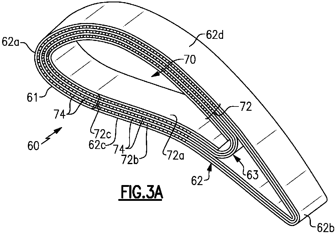
- FIGS 3A and 3B show sectioned views through the airfoil section 62 of the airfoil 60, in which the layered structure of the CMC 70 is shown.
- the airfoil wall 61 includes a lay-up of CMC plies 72 that span the radially inner and outer ends 62e/62f.
- the CMC plies 72 include at least one inner-most CMC ply 72a (inner-most with regard to the cavity 70) that bounds at least a portion of the main cavity 70, at least one exterior skin CMC ply 72b, and intermediate CMC plies 72c located between the inner-most CMC ply 72a and the exterior skin CMC ply 72b.
- each of the inner-most CMC ply 72a and the exterior skin CMC ply 72b are double layers but could alternatively be single layers or have more than two layers.
- the exterior skin CMC ply 72b is continuous plies in that, except for cooling holes, it wraps uninterrupted from the trailing edge 62b on the first side 62c, through the leading edge 62a, and through the second side 62d to the trailing edge 62b on the second side 62d.
- the inner-most CMC ply 72a is also continuous but does not extend all the way to the trailing edge 62b and instead terminates due to a design feature, such as a fillet or radius63 that partitions the cavity 70.
- FIG. 4 A representative section of the airfoil wall 61 is shown in Figure 4 .
- at least one of the intermediate CMC plies 72c has cutout voids 74 that serve as cooling channels in the airfoil wall 61.
- the cutout voids 74 are strips that are elongated in the radial direction and span from the inner end 62e of the airfoil section 62 to the outer end 62f of the airfoil section 62.
- the cooling channels may be fed with cooling air (e.g. compressor bleed air) for cooling the airfoil wall 61.
- the cutout voids 74 are located in the first (pressure) side 62c, the second (suction) side 62d, and the leading edge 62a. It is to be understood, however, that the presence and location of the cooling channels may be tailored to the cooling requirements of the particular airfoil design.
- Each cooling channel is bound on lateral channel sides 74a/74b by the at least one of the intermediate CMC plies 72c, bound on an inner channel side 74c by a first adjacent one of the CMC plies 72 (e.g. either another of the intermediate CMC plies 72c, the inner-most CMC ply 72a, or the exterior skin CMC ply 72b), and bound on an outer channel side 74d by a second, different adjacent one of the CMC plies 72 (e.g. either another of the intermediate CMC plies 72c, the inner-most CMC ply 72a, or the exterior skin CMC ply 72b).
- a first adjacent one of the CMC plies 72 e.g. either another of the intermediate CMC plies 72c, the inner-most CMC ply 72a, or the exterior skin CMC ply 72b
- a second, different adjacent one of the CMC plies 72 e.g. either another of the intermediate CMC plies 72c, the inner-most CMC
- two congruent ones of the intermediate CMC plies 72c have the cutout voids 74 such that the cooling channels have a thickness that is equal to two or more of the CMC plies 72.
- a thickness of two plies facilitates good flow and cooling.
- the cooling channels could have a thickness of one ply or more than two plies.
- the intermediate CMC plies 72c may also include connecting cutout voids 76 that fluidly connect the cooling channels.
- some connecting cutout voids 76 may be intra-connecting between cooling channels within an intermediate CMC ply 72c or set of plies, while other connecting cutout voids 76 may be inter-connecting between cooling channels in different intermediate CMC plies 72c or sets of plies.
- the connecting cutout voids 76 are excluded such that the cooling channels are non-interconnected.
- the inner-most CMC ply 72a of the airfoil wall 61 includes at least one inlet hole 78a connecting the cooling channels with the main cavity 70 and the exterior skin CMC ply 72b includes at least one outlet hole 78b connecting the cooling channels to the exterior of the airfoil 60 (i.e., the hot gas flow).
- the cooling air (shown by flow arrows F) may be provided from the main cavity 70 into the cooling channels via inlet hole 78a and then discharged into the gas path via outlet hole 78b.
- the location, number, and spacing of the cooling channels may be tailored for the cooling requirements of the airfoil 60.
- the cooling channels align in columns 80 in a thickness direction through the airfoil wall 61.
- the cooling channels are staggered in a thickness direction through the airfoil wall. For instance, in the illustrated example there are three rows of cooling channels and the middle row of cooling channels is offset relative to the adjacent rows.
- a portion of the cooling channels have a spacing D1 and another portion of the cooling channels have a larger spacing D2.
- the spacings D1 and D2 may be tailored for cooling requirements.
- the cooling channels are non-uniformly spaced (i.e. have at least two non-equivalent spacings), while in other instances the cooling channels are uniformly spaced (i.e., all have equivalent spacings).
- the cutout voids 74 are represented in their radial extent.
- the cutout voids 74, and thus the cooling channels, are tapered along the radial direction.
- the cooling channel alternate between tapering from the radially outer end 62f to the radially inner end 62e and tapering from the radially inner end 62e to the radially outer end 62f.
- Such a configuration may be useful in a serpentine flow pattern, where the cooling air flow up one channel and then turns to flow down the next channel before being discharged from the trailing edge 62b.
- the cutout voids 74 and channels need not be straight and could include other geometries, such as but not limited to, turns or curves.
- Figure 8 depicts an example method for fabricating the airfoil 60.
- two intermediate ceramic fabric plies are attached back-to-back.
- the plies may be bonded together using an adhesive, such as polyvinyl alcohol polymer. The bonding facilitates keeping the plies aligned for subsequent steps.
- strips are cut in the plies from step (a).
- laser-cutting may be used but other cutting techniques may alternatively be used.
- at least one inner-most ceramic fabric ply is laid-up around a mandrel. For example, to make a double layer, two layers of ceramic fabric are wrapped around the mandrel.
- step (d) the cut intermediate ceramic fabric plies from step (b) are laid-up on the inner-most ceramic fabric ply from step (c) and then at step (e) the cut strips are removed from the cut intermediate ceramic fabric plies, leaving cutout voids 74 as shown in illustration (f).
- step (g) one or more continuous (uncut) intermediate ceramic fabric plies are laid-up on the intermediate ceramic fabric plies that have the cutout voids 74. Steps (a), (b), (d), (e), (f), and (g) may be repeated to lay-up additional intermediate ceramic fabric plies to a desired layer thickness and configuration of cooling channels. In the final iteration, the one or more continuous (uncut) ceramic fabric plies will be for the exterior skin ply.
- the ceramic fabric plies are laid-up to provide an airfoil fiber preform.
- the fiber preform is densified with the ceramic matrix material to form the airfoil wall 61.
- the matrix material is deposited by chemical vapor infiltration, polymer infiltration and pyrolysis, or other method of matrix formation.
Landscapes
- Engineering & Computer Science (AREA)
- Chemical & Material Sciences (AREA)
- Materials Engineering (AREA)
- Ceramic Engineering (AREA)
- Mechanical Engineering (AREA)
- General Engineering & Computer Science (AREA)
- Composite Materials (AREA)
- Manufacturing & Machinery (AREA)
- Structural Engineering (AREA)
- Organic Chemistry (AREA)
- Chemical Kinetics & Catalysis (AREA)
- Turbine Rotor Nozzle Sealing (AREA)
Abstract
An airfoil (60) includes an airfoil wall (61) that circumscribes a main cavity (70) and defines radially inner and outer ends (62e, 62f), leading and trailing edges (62a, 62b), and pressure and suction sides (62c, 62d). The airfoil wall (61) includes a lay-up of ceramic matrix composite (CMC) plies (72) that span the radially inner and outer ends (62e, 62f) and have an inner-most CMC ply (72a) bounding at least a portion of the main cavity (70), an exterior skin CMC ply (72b), and intermediate CMC plies (72c) between the inner-most CMC ply (72a) and the exterior skin CMC ply (72b). At least one of the intermediate CMC plies (72c) has cutout voids (74) that define cooling channels in the airfoil wall (61). The cooling channels are bound on lateral sides (74a, 74b) by the at least one of the intermediate CMC plies (72c), bound on an inner side (74c) by a first adjacent one of the CMC plies (72), and bound on an outer side (74d) by a second, different adjacent one of the CMC plies (72).
Description
- A gas turbine engine typically includes a fan section, a compressor section, a combustor section and a turbine section. Air entering the compressor section is compressed and delivered into the combustion section where it is mixed with fuel and ignited to generate a high-pressure and temperature exhaust gas flow. The high-pressure and temperature exhaust gas flow expands through the turbine section to drive the compressor and the fan section. The compressor section may include low and high pressure compressors, and the turbine section may also include low and high pressure turbines.
- Airfoils in the turbine section are typically formed of a superalloy and may include thermal barrier coatings to extend temperature capability and lifetime. Ceramic matrix composite ("CMC") materials are also being considered for airfoils. Among other attractive properties, CMCs have high temperature resistance. Despite this attribute, however, there are unique challenges to implementing CMCs in airfoils.
- An airfoil according to an example of the present disclosure includes an airfoil wall that circumscribes a main cavity and defines radially inner and outer ends, leading and trailing edges, and pressure and suction sides. The airfoil wall includes a lay-up of ceramic matrix composite (CMC) plies that span the radially inner and outer ends and have an inner-most CMC ply that bounds at least a portion of the main cavity, an exterior skin CMC ply, and intermediate CMC plies between the inner-most CMC ply and the exterior skin CMC ply. At least one of the intermediate CMC plies has cutout voids that define cooling channels in the airfoil wall. The cooling channels are bound on lateral channel sides by the at least one of the intermediate CMC plies, bound on an inner channel side by a first adjacent one of the CMC plies, and bound on an outer channel side by a second, different adjacent one of the CMC plies.
- In a further embodiment of the foregoing example, multiple ones of the intermediate CMC plies have the cutout voids such that the cooling channels form a three-dimensional cooling network.
- In a further embodiment of any of the foregoing examples, multiple ones of the intermediate CMC plies have the cutout voids and the cooling channels are non-interconnected.
- In a further embodiment of any of the foregoing examples, multiple ones of the intermediate CMC plies have the cutout voids and the cooling channels are interconnected.
- In a further embodiment of any of the foregoing examples, the cooling channels are tapered along a radial direction.
- In a further embodiment of any of the foregoing examples, two or more congruent ones of the intermediate CMC plies have the cutout voids such that the cooling channels have a thickness that is equal to two or more of the CMC plies.
- In a further embodiment of any of the foregoing examples, the cooling channels have a thickness and the CMC plies each have a ply thickness, and the thickness of the cooling channels is a multiple of the ply thickness.
- In a further embodiment of any of the foregoing examples, the cooling channels are located in the pressure side, the suction side, and the leading edge.
- In a further embodiment of any of the foregoing examples, the cooling channels are radially elongated.
- In a further embodiment of any of the foregoing examples, multiple ones of the intermediate CMC plies have cutout voids, and the cooling channels align in columns in a thickness direction through the airfoil wall.
- In a further embodiment of any of the foregoing examples, multiple ones of the intermediate CMC plies have cutout voids, and the cooling channels are staggered in a thickness direction through the airfoil wall.
- In a further embodiment of any of the foregoing examples, the inner-most CMC ply includes at least one inlet hole connecting the cooling channels with the main cavity.
- In a further embodiment of any of the foregoing examples, the exterior skin CMC ply includes at least one outlet hole connected with the cooling channels.
- In a further embodiment of any of the foregoing examples, the cooling channels are uniformly spaced apart.
- In a further embodiment of any of the foregoing examples, the cooling channels are non-uniformly spaced apart.
- A gas turbine engine according to an example of the present disclosure includes a compressor section, a combustor in fluid communication with the compressor section, and a turbine section in fluid communication with the combustor. The turbine section has a plurality of airfoils as in any of the foregoing embodiments.
- A method of fabricating an airfoil according to an example of the present disclosure includes laying-up at least one inner-most ceramic fabric ply around a mandrel, laying-up the at least one discontinuous intermediate ceramic fabric ply on the at least one inner-most ceramic fabric ply, the at least one discontinuous intermediate ceramic fabric ply having cutout voids, laying-up at least one exterior skin ceramic fabric ply on the at least one discontinuous intermediate ceramic fabric ply with the cutout voids, the inner-most ceramic fabric ply, the at least one discontinuous intermediate ceramic fabric ply, and the exterior skin ceramic fabric ply together providing an airfoil fiber preform, and densifying the airfoil fiber preform with a ceramic matrix material to form an airfoil wall of an airfoil, wherein the cutout voids define cooling channels in the airfoil wall.
- A further embodiment of the foregoing example includes cutting strips in at least one ceramic fabric ply to provide the at least one discontinuous intermediate ceramic fabric ply, and removing the strips from the at least one discontinuous intermediate ceramic fabric ply to provide the cutout voids.
- A further embodiment of the foregoing example includes laying-up strips of ceramic fabric on the at least one inner-most ceramic fabric ply to provide the at least one discontinuous intermediate ceramic fabric ply.
- The present disclosure may include any one or more of the individual features disclosed above and/or below alone or in any combination thereof.
- The various features and advantages of the present disclosure will become apparent to those skilled in the art from the following detailed description. The drawings that accompany the detailed description can be briefly described as follows.
-
Figure 1 illustrates a gas turbine engine. -
Figure 2 illustrates an airfoil from the turbine section of the engine. -
Figure 3A illustrates a sectioned view of an airfoil. -
Figure 3B illustrates another sectioned view of the airfoil. -
Figure 4 illustrates a representative section of the airfoil wall. -
Figure 5 illustrates another representative section of the airfoil wall, with inlet and outlet holes, -
Figure 6 illustrates another representative section of the airfoil wall, with staggered cooling channels. -
Figure 7 illustrates a representation of the airfoil wall with tapered cooling channels. -
Figure 8 depicts a method of fabricating an airfoil. - In this disclosure, like reference numerals designate like elements where appropriate and reference numerals with the addition of one-hundred or multiples thereof designate modified elements that are understood to incorporate the same features and benefits of the corresponding elements.
-
Figure 1 schematically illustrates agas turbine engine 20. Thegas turbine engine 20 is disclosed herein as a two-spool turbofan that generally incorporates afan section 22, acompressor section 24, acombustor section 26 and aturbine section 28. Thefan section 22 drives air along a bypass flow path B in a bypass duct defined within ahousing 15 such as a fan case or nacelle, and also drives air along a core flow path C for compression and communication into thecombustor section 26 then expansion through theturbine section 28. Although depicted as a two-spool turbofan gas turbine engine in the disclosed non-limiting embodiment, it should be understood that the concepts described herein are not limited to use with two-spool turbofans as the teachings may be applied to other types of turbine engines including three-spool architectures. - The
exemplary engine 20 generally includes alow speed spool 30 and ahigh speed spool 32 mounted for rotation about an engine central longitudinal axis A relative to an enginestatic structure 36 viaseveral bearing systems 38. It should be understood thatvarious bearing systems 38 at various locations may alternatively or additionally be provided, and the location ofbearing systems 38 may be varied as appropriate to the application. - The
low speed spool 30 generally includes aninner shaft 40 that interconnects, a first (or low)pressure compressor 44 and a first (or low)pressure turbine 46. Theinner shaft 40 is connected to the fan 42 through a speed change mechanism, which in exemplarygas turbine engine 20 is illustrated as a gearedarchitecture 48 to drive a fan 42 at a lower speed than thelow speed spool 30. Thehigh speed spool 32 includes anouter shaft 50 that interconnects a second (or high)pressure compressor 52 and a second (or high)pressure turbine 54. Acombustor 56 is arranged in theexemplary gas turbine 20 between thehigh pressure compressor 52 and thehigh pressure turbine 54. Amid-turbine frame 57 of the enginestatic structure 36 may be arranged generally between thehigh pressure turbine 54 and thelow pressure turbine 46. Themid-turbine frame 57 further supports bearingsystems 38 in theturbine section 28. Theinner shaft 40 and theouter shaft 50 are concentric and rotate viabearing systems 38 about the engine central longitudinal axis A which is collinear with their longitudinal axes. - The core airflow is compressed by the
low pressure compressor 44 then thehigh pressure compressor 52, mixed and burned with fuel in thecombustor 56, then expanded through thehigh pressure turbine 54 andlow pressure turbine 46. Themid-turbine frame 57 includesairfoils 59 which are in the core airflow path C. Theturbines low speed spool 30 andhigh speed spool 32 in response to the expansion. It will be appreciated that each of the positions of thefan section 22,compressor section 24,combustor section 26,turbine section 28, and fandrive gear system 48 may be varied. For example,gear system 48 may be located aft of the low pressure compressor, or aft of thecombustor section 26 or even aft ofturbine section 28, and fan 42 may be positioned forward or aft of the location ofgear system 48. - The
engine 20 in one example is a high-bypass geared aircraft engine. In a further example, theengine 20 bypass ratio is greater than about six (6), with an example embodiment being greater than about ten (10), and can be less than or equal to about 18.0, or more narrowly can be less than or equal to 16.0. The gearedarchitecture 48 is an epicyclic gear train, such as a planetary gear system or other gear system, with a gear reduction ratio of greater than about 2.3. The gear reduction ratio may be less than or equal to 4.0. Thelow pressure turbine 46 has a pressure ratio that is greater than about five. The low pressure turbine pressure ratio can be less than or equal to 13.0, or more narrowly less than or equal to 12.0. In one disclosed embodiment, theengine 20 bypass ratio is greater than about ten (10:1), the fan diameter is significantly larger than that of thelow pressure compressor 44, and thelow pressure turbine 46 has a pressure ratio that is greater than about five (5:1).Low pressure turbine 46 pressure ratio is pressure measured prior to an inlet oflow pressure turbine 46 as related to the pressure at the outlet of thelow pressure turbine 46 prior to an exhaust nozzle. The gearedarchitecture 48 may be an epicycle gear train, such as a planetary gear system or other gear system, with a gear reduction ratio of greater than about 2.3: 1 and less than about 5:1. It should be understood, however, that the above parameters are only exemplary of one embodiment of a geared architecture engine and that the present invention is applicable to other gas turbine engines including direct drive turbofans. - A significant amount of thrust is provided by the bypass flow B due to the high bypass ratio. The
fan section 22 of theengine 20 is designed for a particular flight conditiontypically cruise at about 0.8 Mach and about 35,000 feet (10,668 meters). The flight condition of 0.8 Mach and 35,000 ft (10,668 meters), with the engine at its best fuel consumption - also known as "bucket cruise Thrust Specific Fuel Consumption ('TSFC')" - is the industry standard parameter of lbm of fuel being burned divided by lbf of thrust the engine produces at that minimum point. The engine parameters described above and those in this paragraph are measured at this condition unless otherwise specified. "Low fan pressure ratio" is the pressure ratio across the fan blade alone, without a Fan Exit Guide Vane ("FEGV") system. The low fan pressure ratio as disclosed herein according to one non-limiting embodiment is less than about 1.45, or more narrowly greater than or equal to 1.25. "Low corrected fan tip speed" is the actual fan tip speed in ft/sec divided by an industry standard temperature correction of [(Tram °R) / (518.7 °R)]0.5(where °R = K x 9/5). The "Low corrected fan tip speed" as disclosed herein according to one non-limiting embodiment is less than about 1150.0 ft / second (350.5 meters/second), and can be greater than or equal to 1000.0 ft / second (304.8 meters/second). -
Figure 2 illustrates anexample airfoil 60 from theturbine section 28 of the engine 20 (see alsoFigure 1 ). For instance, theairfoil 60 is a vane that is supported between inner and outer support hardware and there aremultiple airfoils 60 arranged in a circumferential row in theengine 20. It is to be understood that although the examples herein may be shown in context of a vane from theturbine section 28, the examples can be applied to turbine blades or other types of airfoils in other portions of theengine 20. - In the illustrated example, the
airfoil 60 is comprised of anairfoil wall 61 that defines anairfoil section 62. Theairfoil section 62 extends between (radially) inner andouter platforms 66/68, which may be integrally formed with theairfoil section 62. It is to be understood, however, that vane designs vary and that some designs may have a single platform or no platforms. Theairfoil section 62 circumscribes an internalmain cavity 70 and defines leading and trailingedges 62a/62b and first andsecond sides 62c/62d that join the leading and trailingedges 62a/62b. In this example, thefirst side 62c is a pressure side and thesecond side 62d is a suction side. Theairfoil section 62 spans radially, relative to the central engine axis A, between a first (inner)radial end 62e to a second (outer)radial end 62f. The terms "first" and "second" as used herein are to differentiate that there are two architecturally distinct components or features. It is to be further understood that the terms "first" and "second" are interchangeable in the embodiments herein in that a first component or feature could alternatively be termed as the second component or feature, and vice versa. - The
airfoil 60 is formed of a ceramic matrix composite (CMC) 70 (shown in partial cutaway view). For example, theCMC 70 includes ceramic fiber tows 70a that are disposed in aceramic matrix 70b. TheCMC 70 may be, but is not limited to, a SiC/SiC ceramic matrix composite in which SiC fiber tows are disposed within a SiC matrix. The fiber tows are provided in a ceramic fabric and arranged in a fiber architecture in the fabric (e.g. braided or harness satin weave). As will be described in further detail later on below, the fabric is laid-up, fabric layer upon fabric layer, to provide theairfoil wall 61. -
Figures 3A and 3B show sectioned views through theairfoil section 62 of theairfoil 60, in which the layered structure of theCMC 70 is shown. Theairfoil wall 61 includes a lay-up of CMC plies 72 that span the radially inner andouter ends 62e/62f. The CMC plies 72 include at least oneinner-most CMC ply 72a (inner-most with regard to the cavity 70) that bounds at least a portion of themain cavity 70, at least one exterior skin CMC ply 72b, and intermediate CMC plies 72c located between theinner-most CMC ply 72a and the exterior skin CMC ply 72b. In this example, each of theinner-most CMC ply 72a and the exterior skin CMC ply 72b are double layers but could alternatively be single layers or have more than two layers. The exteriorskin CMC ply 72b is continuous plies in that, except for cooling holes, it wraps uninterrupted from the trailingedge 62b on thefirst side 62c, through theleading edge 62a, and through thesecond side 62d to the trailingedge 62b on thesecond side 62d. Theinner-most CMC ply 72a is also continuous but does not extend all the way to the trailingedge 62b and instead terminates due to a design feature, such as a fillet or radius63 that partitions thecavity 70. - A representative section of the
airfoil wall 61 is shown inFigure 4 . As shown, at least one of the intermediate CMC plies 72c has cutout voids 74 that serve as cooling channels in theairfoil wall 61. The cutout voids 74 are strips that are elongated in the radial direction and span from theinner end 62e of theairfoil section 62 to theouter end 62f of theairfoil section 62. In this regard, the cooling channels may be fed with cooling air (e.g. compressor bleed air) for cooling theairfoil wall 61. As shown inFigure 3B , the cutout voids 74, and thus the cooling channels, are located in the first (pressure)side 62c, the second (suction)side 62d, and theleading edge 62a. It is to be understood, however, that the presence and location of the cooling channels may be tailored to the cooling requirements of the particular airfoil design. - Each cooling channel is bound on
lateral channel sides 74a/74b by the at least one of the intermediate CMC plies 72c, bound on aninner channel side 74c by a first adjacent one of the CMC plies 72 (e.g. either another of the intermediate CMC plies 72c, theinner-most CMC ply 72a, or the exteriorskin CMC ply 72b), and bound on anouter channel side 74d by a second, different adjacent one of the CMC plies 72 (e.g. either another of the intermediate CMC plies 72c, theinner-most CMC ply 72a, or the exteriorskin CMC ply 72b). In the illustrated example inFigure 3B , two congruent ones of the intermediate CMC plies 72c have the cutout voids 74 such that the cooling channels have a thickness that is equal to two or more of the CMC plies 72. A thickness of two plies facilitates good flow and cooling. Alternatively, however, if cooling requirements permit, the cooling channels could have a thickness of one ply or more than two plies. - In the illustrated example, multiple ones of the intermediate CMC plies 72c have the cutout voids 74 such that the cooling channels form a three-dimensional cooling network. In this regard, the intermediate CMC plies 72c may also include connecting cutout voids 76 that fluidly connect the cooling channels. For instance, some connecting cutout voids 76 may be intra-connecting between cooling channels within an
intermediate CMC ply 72c or set of plies, while other connecting cutout voids 76 may be inter-connecting between cooling channels in different intermediate CMC plies 72c or sets of plies. Alternatively, the connecting cutout voids 76 are excluded such that the cooling channels are non-interconnected. - In a further example shown in
Figure 5 , theinner-most CMC ply 72a of theairfoil wall 61 includes at least oneinlet hole 78a connecting the cooling channels with themain cavity 70 and the exteriorskin CMC ply 72b includes at least one outlet hole 78b connecting the cooling channels to the exterior of the airfoil 60 (i.e., the hot gas flow). In this configuration, the cooling air (shown by flow arrows F) may be provided from themain cavity 70 into the cooling channels viainlet hole 78a and then discharged into the gas path via outlet hole 78b. - The location, number, and spacing of the cooling channels may be tailored for the cooling requirements of the
airfoil 60. In the example shown (e.g.,Figure 4 ), the cooling channels align incolumns 80 in a thickness direction through theairfoil wall 61. Alternatively, in another example shown inFigure 6 , the cooling channels are staggered in a thickness direction through the airfoil wall. For instance, in the illustrated example there are three rows of cooling channels and the middle row of cooling channels is offset relative to the adjacent rows. - As also shown in
Figure 4 , a portion of the cooling channels have a spacing D1 and another portion of the cooling channels have a larger spacing D2. The spacings D1 and D2 may be tailored for cooling requirements. In some instances, as shown, the cooling channels are non-uniformly spaced (i.e. have at least two non-equivalent spacings), while in other instances the cooling channels are uniformly spaced (i.e., all have equivalent spacings). - In another example shown in
Figure 7 , the cutout voids 74 are represented in their radial extent. The cutout voids 74, and thus the cooling channels, are tapered along the radial direction. For instance, the cooling channel alternate between tapering from the radiallyouter end 62f to the radiallyinner end 62e and tapering from the radiallyinner end 62e to the radiallyouter end 62f. Such a configuration may be useful in a serpentine flow pattern, where the cooling air flow up one channel and then turns to flow down the next channel before being discharged from the trailingedge 62b. As will be appreciated, the cutout voids 74 and channels need not be straight and could include other geometries, such as but not limited to, turns or curves. -
Figure 8 depicts an example method for fabricating theairfoil 60. At step (a), two intermediate ceramic fabric plies are attached back-to-back. For example, the plies may be bonded together using an adhesive, such as polyvinyl alcohol polymer. The bonding facilitates keeping the plies aligned for subsequent steps. At step (b), strips are cut in the plies from step (a). As an example, laser-cutting may be used but other cutting techniques may alternatively be used. At step (c), at least one inner-most ceramic fabric ply is laid-up around a mandrel. For example, to make a double layer, two layers of ceramic fabric are wrapped around the mandrel. At step (d), the cut intermediate ceramic fabric plies from step (b) are laid-up on the inner-most ceramic fabric ply from step (c) and then at step (e) the cut strips are removed from the cut intermediate ceramic fabric plies, leaving cutout voids 74 as shown in illustration (f). At step (g), one or more continuous (uncut) intermediate ceramic fabric plies are laid-up on the intermediate ceramic fabric plies that have the cutout voids 74. Steps (a), (b), (d), (e), (f), and (g) may be repeated to lay-up additional intermediate ceramic fabric plies to a desired layer thickness and configuration of cooling channels. In the final iteration, the one or more continuous (uncut) ceramic fabric plies will be for the exterior skin ply. In this manner, the ceramic fabric plies are laid-up to provide an airfoil fiber preform. Finally, at step (h), the fiber preform is densified with the ceramic matrix material to form theairfoil wall 61. For example, the matrix material is deposited by chemical vapor infiltration, polymer infiltration and pyrolysis, or other method of matrix formation. - Alternatively, rather using steps (b)-(f), individual strips of the fabric could be cut and removed prior to being laid-up on the inner-most ceramic fabric ply, and then each individual strip could be laid-up on the inner-most ceramic fabric ply from illustration (c). In that case, the cutout voids 74 would be the negative space left between the strips. From the standpoint of time, however, laying-up individual strips may be more labor intensive. On the other hand, for strip geometries that are not straight or that are curved, laying-up individual strips may be desirable to enable adjustment of the locations of the strips.
- Although a combination of features is shown in the illustrated examples, not all of them need to be combined to realize the benefits of various embodiments of this disclosure. In other words, a system designed according to an embodiment of this disclosure will not necessarily include all of the features shown in any one of the Figures or all of the portions schematically shown in the Figures. Moreover, selected features of one example embodiment may be combined with selected features of other example embodiments.
- The preceding description is exemplary rather than limiting in nature. Variations and modifications to the disclosed examples may become apparent to those skilled in the art that do not necessarily depart from this disclosure. The scope of legal protection given to this disclosure can only be determined by studying the following claims.
Claims (15)
- An airfoil (60) comprising:
an airfoil wall (61) circumscribing a main cavity (70) and defining radially inner and outer ends (62e, 62f), leading and trailing edges (62a, 62b), and pressure and suction sides (62c, 62d), the airfoil wall (61) including a lay-up of ceramic matrix composite (CMC) plies (72) spanning the radially inner and outer ends (62e, 62f) and having an inner-most CMC ply (72a) bounding at least a portion of the main cavity (70), an exterior skin CMC ply (72b), and intermediate CMC plies (72c) between the inner-most CMC ply (72a) and the exterior skin CMC ply (72b), at least one of the intermediate CMC plies (72c) having cutout voids (74) that define cooling channels in the airfoil wall (61), the cooling channels being bound on lateral channel sides (74a, 74b) by the at least one of the intermediate CMC plies (72c), bound on an inner channel side (74c) by a first adjacent one of the CMC plies (72), and bound on an outer channel side (74d) by a second, different adjacent one of the CMC plies (72). - The airfoil (60) as recited in claim 1, wherein multiple ones of the intermediate CMC plies (72c) have the cutout voids (74) such that the cooling channels form a three-dimensional cooling network.
- The airfoil (60) as recited in claim 1 or 2, wherein multiple ones of the intermediate CMC plies (72c) have the cutout voids (74) and the cooling channels are non-interconnected.
- The airfoil (60) as recited in claim 1 or 2, wherein multiple ones of the intermediate CMC plies (72c) have the cutout voids (74) and the cooling channels are interconnected.
- The airfoil (60) as recited in any preceding claim, wherein the cooling channels are tapered along a radial direction.
- The airfoil (60) as recited in any preceding claim, wherein two or more congruent ones of the intermediate CMC plies (72c) have the cutout voids (74) such that the cooling channels have a thickness that is equal to two or more of the CMC plies (72).
- The airfoil (60) as recited in any preceding claim, wherein:the cooling channels have a thickness and the CMC plies (72) each have a ply thickness, and the thickness of the cooling channels is a multiple of the ply thickness; and/orthe cooling channels are radially elongated.
- The airfoil (60) as recited in any preceding claim, wherein the cooling channels are located in the pressure side (62c), the suction side (62d), and the leading edge (62a).
- The airfoil (60) as recited in any preceding claim, wherein multiple ones of the intermediate CMC plies (72c) have cutout voids (74), and the cooling channels align in columns (80) in a thickness direction through the airfoil wall (61).
- The airfoil (60) as recited in any of claims 1 to 8, wherein multiple ones of the intermediate CMC plies (72c) have cutout voids (74), and the cooling channels are staggered in a thickness direction through the airfoil wall (61).
- The airfoil (60) as recited in any preceding claim, wherein the inner-most CMC ply (72a) includes at least one inlet hole (78a) connecting the cooling channels with the main cavity (70),
wherein, optionally, the exterior skin CMC ply (72b) includes at least one outlet hole (78b) connected with the cooling channels. - The airfoil (60) as recited in any preceding claim, wherein:the cooling channels are uniformly spaced apart; orthe cooling channels are non-uniformly spaced apart.
- A gas turbine engine (20) comprising:a compressor section (24);a combustor (56) in fluid communication with the compressor section (24); anda turbine section (28) in fluid communication with the combustor (56), the turbine section (28) having a plurality of airfoils (60) according to any preceding claim.
- A method of fabricating an airfoil (60) comprising:laying-up at least one inner-most ceramic fabric ply around a mandrel;laying-up the at least one discontinuous intermediate ceramic fabric ply on the at least one inner-most ceramic fabric ply, the at least one discontinuous intermediate ceramic fabric ply having cutout voids (74);laying-up at least one exterior skin ceramic fabric ply on the at least one discontinuous intermediate ceramic fabric ply with the cutout voids (74), the inner-most ceramic fabric ply, the at least one discontinuous intermediate ceramic fabric ply, and the exterior skin ceramic fabric ply together providing an airfoil fiber preform; anddensifying the airfoil fiber preform with a ceramic matrix material to form an airfoil wall (61) of an airfoil (60), wherein the cutout voids (74) define cooling channels in the airfoil wall (61).
- The method as recited in claim 14, further including:cutting strips in at least one ceramic fabric ply to provide the at least one discontinuous intermediate ceramic fabric ply, and removing the strips from the at least one discontinuous intermediate ceramic fabric ply to provide the cutout voids (74); orlaying-up strips of ceramic fabric on the at least one inner-most ceramic fabric ply to provide the at least one discontinuous intermediate ceramic fabric ply.
Applications Claiming Priority (1)
| Application Number | Priority Date | Filing Date | Title |
|---|---|---|---|
| US18/195,149 US12078081B1 (en) | 2023-05-09 | 2023-05-09 | Airfoil with CMC ply cutouts for cooling channels |
Publications (1)
| Publication Number | Publication Date |
|---|---|
| EP4461928A1 true EP4461928A1 (en) | 2024-11-13 |
Family
ID=91070170
Family Applications (1)
| Application Number | Title | Priority Date | Filing Date |
|---|---|---|---|
| EP24175016.5A Pending EP4461928A1 (en) | 2023-05-09 | 2024-05-09 | Airfoil with cmc-ply cutouts for cooling channels, gas turbine engine and method of fabricating an airfoil |
Country Status (2)
| Country | Link |
|---|---|
| US (1) | US12078081B1 (en) |
| EP (1) | EP4461928A1 (en) |
Families Citing this family (2)
| Publication number | Priority date | Publication date | Assignee | Title |
|---|---|---|---|---|
| US12601267B2 (en) * | 2024-02-15 | 2026-04-14 | Rtx Corporation | Forming gas turbine engine airfoils from CMCs with a kickback to facilitate mandrel removal |
| US12584418B2 (en) * | 2024-08-15 | 2026-03-24 | Rtx Corporation | CMC component with cooling cavity |
Citations (4)
| Publication number | Priority date | Publication date | Assignee | Title |
|---|---|---|---|---|
| US20170122113A1 (en) * | 2015-10-29 | 2017-05-04 | General Electric Company | Ceramic matrix composite component and process of producing a ceramic matrix composite component |
| US20170328216A1 (en) * | 2016-05-11 | 2017-11-16 | General Electric Company | Ceramic matrix composite airfoil cooling |
| US20180328189A1 (en) * | 2017-05-11 | 2018-11-15 | General Electric Company | Cmc components having microchannels and methods for forming microchannels in cmc components |
| US20210189886A1 (en) * | 2019-12-20 | 2021-06-24 | General Electric Company | Ceramic matrix composite component including cooling channels and method of producing |
Family Cites Families (6)
| Publication number | Priority date | Publication date | Assignee | Title |
|---|---|---|---|---|
| US6746755B2 (en) * | 2001-09-24 | 2004-06-08 | Siemens Westinghouse Power Corporation | Ceramic matrix composite structure having integral cooling passages and method of manufacture |
| US7413406B2 (en) * | 2006-02-15 | 2008-08-19 | United Technologies Corporation | Turbine blade with radial cooling channels |
| US20180223681A1 (en) | 2017-02-09 | 2018-08-09 | General Electric Company | Turbine engine shroud with near wall cooling |
| US10626735B2 (en) * | 2017-12-05 | 2020-04-21 | United Technologies Corporation | Double wall turbine gas turbine engine blade cooling configuration |
| WO2019215913A1 (en) | 2018-05-11 | 2019-11-14 | 川崎重工業株式会社 | Shroud assembly for gas turbine |
| US11326470B2 (en) | 2019-12-20 | 2022-05-10 | General Electric Company | Ceramic matrix composite component including counterflow channels and method of producing |
-
2023
- 2023-05-09 US US18/195,149 patent/US12078081B1/en active Active
-
2024
- 2024-05-09 EP EP24175016.5A patent/EP4461928A1/en active Pending
Patent Citations (4)
| Publication number | Priority date | Publication date | Assignee | Title |
|---|---|---|---|---|
| US20170122113A1 (en) * | 2015-10-29 | 2017-05-04 | General Electric Company | Ceramic matrix composite component and process of producing a ceramic matrix composite component |
| US20170328216A1 (en) * | 2016-05-11 | 2017-11-16 | General Electric Company | Ceramic matrix composite airfoil cooling |
| US20180328189A1 (en) * | 2017-05-11 | 2018-11-15 | General Electric Company | Cmc components having microchannels and methods for forming microchannels in cmc components |
| US20210189886A1 (en) * | 2019-12-20 | 2021-06-24 | General Electric Company | Ceramic matrix composite component including cooling channels and method of producing |
Also Published As
| Publication number | Publication date |
|---|---|
| US12078081B1 (en) | 2024-09-03 |
Similar Documents
| Publication | Publication Date | Title |
|---|---|---|
| EP2961935B1 (en) | Gas turbine engine thin wall composite vane airfoil | |
| US20210131302A1 (en) | Feather seal slot arrangement for a cmc boas assembly | |
| EP2961938B1 (en) | Gas turbine engine composite airfoil and method | |
| EP4461928A1 (en) | Airfoil with cmc-ply cutouts for cooling channels, gas turbine engine and method of fabricating an airfoil | |
| EP3919248A2 (en) | Multi-piece mandrel for cmc components | |
| EP4283095B1 (en) | Cmc laminate airfoil with ply drops | |
| EP4461713A1 (en) | Seal arc segment with cmc-ply cutouts for cooling channels, gas turbine engine and method of fabricating a seal arc segment | |
| EP4471254A1 (en) | Airfoil with sandwich composite flange | |
| EP3825516A1 (en) | Vane with collar | |
| EP4534803A1 (en) | Airfoil, gas turbine engine and method of fabricating an airfoil | |
| EP4534802A1 (en) | Airfoil, gas turbine engine and method of fabricating an airfoil | |
| EP4545755A1 (en) | Airfoil and gas turbine engine | |
| EP3974617B1 (en) | Ceramic gas turbine engine airfoil with 3 zones film cooling hole pattern having different pitch | |
| EP4484825A1 (en) | Combustor liner with pattern of voids in cmc fiber ply for cooling channels | |
| EP3825519B1 (en) | Airfoil assembly for a gas turbine engine, corresponding vane and method of assembling a vane | |
| EP4461925A1 (en) | Method for cmc airfoil using core tube of rigidized ceramic fabric | |
| EP4015772B1 (en) | Gas turbine airfoil with spar comprising an embedded plenum passage | |
| US11098608B2 (en) | CMC BOAS with internal support structure | |
| EP4306772B1 (en) | Airfoil vane multiplet with interleaved fiber plies | |
| EP4545756A1 (en) | Airfoil and gas turbine engine | |
| US12326100B1 (en) | Gas turbine engine component fillets formed of CMC plies | |
| EP4442671A1 (en) | Method for manufacturing multiple seal arc segments | |
| EP4549701A1 (en) | Combined gas turbine engine vane and blade outer air seal assembly and gas turbine engine | |
| EP3808940A1 (en) | Cmc airfoil with cooling holes | |
| EP3712383A1 (en) | Cmc blade outer air seal |
Legal Events
| Date | Code | Title | Description |
|---|---|---|---|
| PUAI | Public reference made under article 153(3) epc to a published international application that has entered the european phase |
Free format text: ORIGINAL CODE: 0009012 |
|
| STAA | Information on the status of an ep patent application or granted ep patent |
Free format text: STATUS: THE APPLICATION HAS BEEN PUBLISHED |
|
| AK | Designated contracting states |
Kind code of ref document: A1 Designated state(s): AL AT BE BG CH CY CZ DE DK EE ES FI FR GB GR HR HU IE IS IT LI LT LU LV MC ME MK MT NL NO PL PT RO RS SE SI SK SM TR |
|
| STAA | Information on the status of an ep patent application or granted ep patent |
Free format text: STATUS: REQUEST FOR EXAMINATION WAS MADE |
|
| 17P | Request for examination filed |
Effective date: 20250513 |