EP4461854A1 - Yarn heater and yarn processor - Google Patents
Yarn heater and yarn processor Download PDFInfo
- Publication number
- EP4461854A1 EP4461854A1 EP24170709.0A EP24170709A EP4461854A1 EP 4461854 A1 EP4461854 A1 EP 4461854A1 EP 24170709 A EP24170709 A EP 24170709A EP 4461854 A1 EP4461854 A1 EP 4461854A1
- Authority
- EP
- European Patent Office
- Prior art keywords
- yarn
- running grooves
- yarns
- heater
- yarn running
- Prior art date
- Legal status (The legal status is an assumption and is not a legal conclusion. Google has not performed a legal analysis and makes no representation as to the accuracy of the status listed.)
- Granted
Links
Images




Classifications
-
- D—TEXTILES; PAPER
- D02—YARNS; MECHANICAL FINISHING OF YARNS OR ROPES; WARPING OR BEAMING
- D02G—CRIMPING OR CURLING FIBRES, FILAMENTS, THREADS, OR YARNS; YARNS OR THREADS
- D02G1/00—Producing crimped or curled fibres, filaments, yarns, or threads, giving them latent characteristics
- D02G1/02—Producing crimped or curled fibres, filaments, yarns, or threads, giving them latent characteristics by twisting, fixing the twist and backtwisting, i.e. by imparting false twist
- D02G1/0206—Producing crimped or curled fibres, filaments, yarns, or threads, giving them latent characteristics by twisting, fixing the twist and backtwisting, i.e. by imparting false twist by false-twisting
-
- D—TEXTILES; PAPER
- D02—YARNS; MECHANICAL FINISHING OF YARNS OR ROPES; WARPING OR BEAMING
- D02J—FINISHING OR DRESSING OF FILAMENTS, YARNS, THREADS, CORDS, ROPES OR THE LIKE
- D02J13/00—Heating or cooling the yarn, thread, cord, rope, or the like, not specific to any one of the processes provided for in this subclass
-
- D—TEXTILES; PAPER
- D02—YARNS; MECHANICAL FINISHING OF YARNS OR ROPES; WARPING OR BEAMING
- D02G—CRIMPING OR CURLING FIBRES, FILAMENTS, THREADS, OR YARNS; YARNS OR THREADS
- D02G1/00—Producing crimped or curled fibres, filaments, yarns, or threads, giving them latent characteristics
- D02G1/02—Producing crimped or curled fibres, filaments, yarns, or threads, giving them latent characteristics by twisting, fixing the twist and backtwisting, i.e. by imparting false twist
- D02G1/0206—Producing crimped or curled fibres, filaments, yarns, or threads, giving them latent characteristics by twisting, fixing the twist and backtwisting, i.e. by imparting false twist by false-twisting
- D02G1/0266—Producing crimped or curled fibres, filaments, yarns, or threads, giving them latent characteristics by twisting, fixing the twist and backtwisting, i.e. by imparting false twist by false-twisting false-twisting machines
-
- D—TEXTILES; PAPER
- D02—YARNS; MECHANICAL FINISHING OF YARNS OR ROPES; WARPING OR BEAMING
- D02G—CRIMPING OR CURLING FIBRES, FILAMENTS, THREADS, OR YARNS; YARNS OR THREADS
- D02G1/00—Producing crimped or curled fibres, filaments, yarns, or threads, giving them latent characteristics
- D02G1/02—Producing crimped or curled fibres, filaments, yarns, or threads, giving them latent characteristics by twisting, fixing the twist and backtwisting, i.e. by imparting false twist
- D02G1/0206—Producing crimped or curled fibres, filaments, yarns, or threads, giving them latent characteristics by twisting, fixing the twist and backtwisting, i.e. by imparting false twist by false-twisting
- D02G1/0266—Producing crimped or curled fibres, filaments, yarns, or threads, giving them latent characteristics by twisting, fixing the twist and backtwisting, i.e. by imparting false twist by false-twisting false-twisting machines
- D02G1/0273—Producing crimped or curled fibres, filaments, yarns, or threads, giving them latent characteristics by twisting, fixing the twist and backtwisting, i.e. by imparting false twist by false-twisting false-twisting machines threading up and starting the false-twisting machine
-
- D—TEXTILES; PAPER
- D02—YARNS; MECHANICAL FINISHING OF YARNS OR ROPES; WARPING OR BEAMING
- D02J—FINISHING OR DRESSING OF FILAMENTS, YARNS, THREADS, CORDS, ROPES OR THE LIKE
- D02J13/00—Heating or cooling the yarn, thread, cord, rope, or the like, not specific to any one of the processes provided for in this subclass
- D02J13/003—Heating or cooling the yarn, thread, cord, rope, or the like, not specific to any one of the processes provided for in this subclass by contact with at least one stationary surface, e.g. a plate
Definitions
- the present invention relates to a yarn heater for heating yarns and a yarn processor including the yarn heater.
- Patent Literature 1 Japanese Laid-Open Patent Publication No. H1-183546 discloses a thermal yarn processor (yarn heater) in which two yarn running grooves are formed and which includes a heat conductor (heating unit) heated by a heat generator and a heat insulating material (heat insulator). Such a thermal yarn processor is configured to heat yarns running in the respective yarn running grooves.
- the two yarn running grooves extend along a first direction and are aligned in a second direction orthogonal to the first direction. Each yarn running groove is open on one side in a third direction which is orthogonal to both the first direction and the second direction.
- the heat insulating material extends along the first direction and is attached to an end face of the heat conductor, where the yarn running grooves are open.
- the heat insulating material has two yarn insertion slits (yarn guide passages) which are independent from each other and are provided to insert yarns into the respective two yarn running grooves.
- An object of the present invention is to provide a yarn heater capable of reducing power consumption and a yarn processor.
- a yarn heater is a yarn heater in which at least two yarn running grooves in which yarns run are formed, the at least two yarn running grooves being aligned in a second direction orthogonal to a first direction in which the yarn running grooves extend.
- the yarn heater includes: a heating unit which extends along the first direction and is configured to heat the yarns running in the at least two yarn running grooves; and a heat insulator which extends along the first direction and is provided on the opposite side of the at least two yarn running grooves over open ends of the at least two yarn running grooves in a third direction orthogonal to the first direction and the second direction.
- a yarn guide passage is formed to allow the yarns to pass through and to introduce the yarns into the at least two yarn running grooves, respectively, at least part of the yarn guide passage functions as a common passage shared between the at least two yarn running grooves
- the yarn guide passage includes: a narrow portion which is formed as at least part of the common passage and has a width that is narrower in the second direction than a total width in the second direction of the at least two yarn running grooves; and a wide portion whose width in the second direction increases toward the at least two yarn running grooves, the wide portion is a part of the yarn guide passage on the yarn running groove side in the third direction of the narrow portion, and an end portion on the yarn running groove side of the wide portion opposing entirety of the at least two yarn running grooves
- the yarn heater further includes at least one partition member which is made of a heat insulating material, extends along the first direction, and divides the yarn guide passage into individual passages corresponding to the respective at least two yarn running grooves, at the wide portion of the
- the yarn guide passage is a common passage shared between the at least two yarn running grooves.
- the yarn guide passage has a narrow portion formed as at least part of a common passage and having a width that is narrower than the sum of the widths of the two yarn running grooves.
- the yarns inserted into the yarn guide passage pass through the narrow portion and then pass through the wide portion opposing entirety of the at least two yarn running grooves, the yarns can be easily inserted into the respective at least two yarn running grooves.
- the aspect of the present invention it is possible to further suppress the inflow and outflow of air to and from the yarn running groove through the yarn guide passage by the partition member. Therefore, the power consumption is reliably reduced.
- the yarn heater of the first aspect of the invention is arranged such that the length in the third direction of the narrow portion of the yarn guide passage is 20mm or more.
- the narrow portion is sufficiently long, circulation of air through the narrow portion is suppressed. On this account, it is possible to further reliably suppress the inflow and outflow of air to and from the yarn running grooves through the yarn guide passages. Therefore, the power consumption can be further decreased.
- the yarn heater of the first or second aspect of the invention is arranged such that the heat insulator is configured to be detachable.
- the yarn guide passage at least partially serves as a common passage for the plural yarn running grooves, the heat insulator in which the yarn guide passage is formed becomes an obstacle to remove the yarn when yarn breakage occurs.
- the removal of the yarn becomes easy by detaching the heat insulator in which the yarn guide passage is formed.
- the yarn heater of any one of the first to third aspects of the invention is arranged such that the heating unit is a contactless heater by which the yarns are heated by heated air.
- the heating temperature is relatively high. According to the aspect of the present invention, it is possible to suppress the release of heat from the heating unit having a relatively high heating temperature to the outside. Due to this, the power consumption is effectively reduced.
- the yarn heater according to any one of the first to fourth aspects of the invention further includes a guider provided at least on one side in the first direction of the heat insulator, in the guider.
- a slit is formed to guide the yarns when the yarns are inserted into the at least two yarn running grooves through the yarn guide passage.
- the slit has an inlet section which is shared between the at least two yarn running grooves and at least two branching sections which are branched from the inlet section to guide the yarns to the respective at least two yarn running grooves.
- the inlet section of the slit formed in the guider is shared between the at least two yarn running grooves. Therefore, the guider can suppress the flow of air through the end portion of the yarn guide passage in the extending direction, and can reliably suppress the inflow and outflow of air to and from the yarn running groove. Therefore, the power consumption is further reduced.
- a yarn heater according to a sixth aspect of the invention is a yarn heater in which at least two yarn running grooves in which yarns run are formed, the at least two yarn running grooves being aligned in a second direction orthogonal to a first direction in which the yarn running grooves extend.
- the yarn heater includes: a heating unit which extends along the first direction and is configured to heat the yarns running in the at least two yarn running grooves; a heat insulator which extends along the first direction and is provided on the opposite side of the at least two yarn running grooves over open ends of the at least two yarn running grooves in a third direction orthogonal to the first direction and the second direction; and at least one guider provided at least on one side in the first direction of the heat insulator.
- a yarn guide passage is formed to allow the yarns to pass through and to introduce the yarns into the at least two yarn running grooves, respectively, at least part of the yarn guide passage functions as a common passage shared between the at least two yarn running grooves, and the yarn guide passage includes a narrow portion which is formed as at least part of the common passage and has a width that is narrower in the second direction than a total width in the second direction of the at least two yarn running grooves.
- a slit is formed to guide the yarns when the yarns are inserted into the at least two yarn running grooves through the yarn guide passage, and the slit has an inlet section which is shared between the at least two yarn running grooves and at least two branching sections which are branched from the inlet section to guide the yarns to the respective at least two yarn running grooves.
- the yarn guide passage is a common passage shared between the at least two yarn running grooves.
- the yarn guide passage has a narrow portion formed as at least part of a common passage and having a width that is narrower than the sum of the widths of the two yarn running grooves.
- the inlet section of the slit formed in the guider is shared between the at least two yarn running grooves. Therefore, the guider can suppress the flow of air through the end portion of the yarn guide passage in the extending direction, and can reliably suppress the inflow and outflow of air to and from the yarn running groove. Therefore, the power consumption is further reduced.
- the yarn heater of the sixth aspect of the invention is arranged such that the length in the third direction of the narrow portion of the yarn guide passage is 20mm or more.
- the narrow portion is sufficiently long, circulation of air through the narrow portion is suppressed. On this account, it is possible to further reliably suppress the inflow and outflow of air to and from the yarn running grooves through the yarn guide passages. Therefore, the power consumption can be further decreased.
- the yarn heater of the sixth or seventh aspect of the invention is arranged such that the heat insulator is configured to be detachable.
- the yarn guide passage at least partially serves as a common passage for the plural yarn running grooves, the heat insulator in which the yarn guide passage is formed becomes an obstacle to remove the yarn when yarn breakage occurs.
- the removal of the yarn becomes easy by detaching the heat insulator in which the yarn guide passage is formed.
- the yarn heater of any one of the sixth to eighth aspects of the invention is arranged such that the yarn guide passage further includes a wide portion whose width in the second direction increases toward the at least two yarn running grooves, and the wide portion is a part of the yarn guide passage on the yarn running groove side in the third direction of the narrow portion and an end portion on the yarn running groove side of the wide portion opposing entirety of the at least two yarn running grooves.
- the yarns inserted into the yarn guide passage pass through the narrow portion and then pass through the wide portion opposing entirety of the at least two yarn running grooves, the yarns can be easily inserted into the respective at least two yarn running grooves.
- the yarn heater of the ninth aspect of the invention further includes at least one partition member which is made of a heat insulating material, extends along the first direction, and divides the yarn guide passage into individual passages corresponding to the respective at least two yarn running grooves, at the wide portion of the yarn guide passage.
- the aspect of the present invention it is possible to further suppress the inflow and outflow of air to and from the yarn running groove through the yarn guide passage by the partition member. Therefore, the power consumption is reliably reduced.
- the yarn heater of any one of the sixth to tenth aspects of the invention is arranged such that the heating unit is a contactless heater by which the yarns are heated by heated air.
- the heating temperature is relatively high. According to the aspect of the present invention, it is possible to suppress the release of heat from the heating unit having a relatively high heating temperature to the outside. Due to this, the power consumption is effectively reduced.
- a yarn processor configured to process yarns includes: the yarn heater according to any one of the fifth to eleventh aspects of the invention, in which two yarn running grooves are formed; a first yarn path formation device which is able to support two yarns to be runnable and is provided on the one side in the first direction of the yarn heater; and a second yarn path formation device which is able to support two yarns to be runnable and is provided on the other side in the first direction of the yarn heater, the other side being opposite to the one side.
- the two yarn paths formed by the first yarn path formation device and the second yarn path formation device are on the respective sides of the inlet section of the slit in the second direction, when viewed in the first direction.
- the yarns when the yarns pass through the inlet section of the slit, the yarns are pulled in the second direction towards the outside of the slit. This allows each of the two yarns to move toward the branching section that is close to the yarn path of that yarn in the second direction. On this account, it is possible to prevent each of the two yarns from passing through a branching section that the each yarn is not supposed to pass, and to prevent each of the yarns from being guided to an erroneous yarn running groove.
- the yarn processor of the twelfth aspect of the invention is arranged such that the guiders are provided on the respective sides of the heat insulator in the first direction.
- the second yarn path formation device is movable in the third direction between a heating position where yarn paths formed between the second yarn path formation device and the first yarn path formation device extend along the first direction in the at least two yarn running grooves and a retracted position which is on the opposite side of the at least two yarn running grooves over the inlet section of the slit in the third direction.
- the inlet section of the slit formed in the guiders on the opposite side of the heat insulator in the first direction includes an extension portion which extends to reach the side opposite to the heating unit over the heat insulator in the third direction, and the width in the second direction of the extension portion increases away from the heating unit.
- the two yarns supported by the second yarn path formation device are reliably guided to the inlet section of the slit.
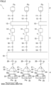
- a false-twist texturing machine 1 of a preferred embodiment of the present invention will be described with reference to FIG. 1 .
- a vertical direction to the sheet of FIG. 1 is defined as a base longitudinal direction, and a left-right direction to the sheet is defined as a base width direction.
- a direction orthogonal to both the base longitudinal direction and the base width direction is defined as an up-down direction in which the gravity acts.
- the base longitudinal direction and the base width direction are substantially in parallel to the horizontal direction.
- the false-twist texturing machine 1 can perform false twisting of yarns Y made of, for example, synthetic fibers such as nylon (polyamide fibers) and polyester.
- the false-twist texturing machine 1 includes a yarn supplying unit 2 for supplying the yarns Y, a processing unit 3 which performs the false twisting of the yarns Y supplied from the yarn supplying unit 2, and a winding unit 4 which winds the yarns Y processed by the processing unit 3 onto a winding bobbins Bw.
- Components of the yarn supplying unit 2, the processing unit 3, and the winding unit 4 are aligned to form plural lines (see FIG. 2 ) in the base longitudinal direction.
- the base longitudinal direction is a direction orthogonal to a running plane (plane of FIG. 1 ) of the yarns Y, which is formed by a yarn path extending from the yarn supplying unit 2 to the winding unit 4 through the processing unit 3.
- the yarn supplying unit 2 includes a creel stand 5 retaining yarn supply packages Ps.
- the yarn supplying unit 2 supplies multiple yarns Y to the processing unit 3.
- the processing unit 3 false-twists a yarn Y supplied from a yarn supply package Ps.
- the following members are provided in this order from the upstream in a yarn running direction: first feed rollers 11; a twist-stopping guide 12; a first heater 13 (equivalent to a yarn heater of the present invention); a cooler 14; a false-twisting device 15; second feed rollers 16; an interlacing device 17; third feed rollers 18; a second heater 19; and fourth feed rollers 20.
- the winding unit 4 includes a plurality of winding devices 21. Each winding device 21 winds a corresponding yarn Y which has been false-twisted by the processing unit 3 onto a winding bobbin Bw and forms a wound package Pw.
- the false-twist texturing machine 1 includes a main base 8 and a winding base 9 which are placed to be spaced apart from each other in the base width direction.
- the main base 8 and the winding base 9 are provided to extend in the base longitudinal direction and to be substantial identical in length.
- the main base 8 and the winding base 9 are arranged to face each other in the base width direction.
- An upper part of the main base 8 is connected to an upper part of the winding base 9 by a supporting frame 10.
- Each device forming the processing unit 3 is mainly attached to the main base 8 or the supporting frame 10.
- Each device forming the winding unit 4 is attached to the winding base 9.
- the main base 8, the winding base 9, and the supporting frame 10 form a working space A in which an operator performs an operation such as yarn threading to each device.
- the yarn paths are formed so that the yarns Y are able to run mainly around the working space A.
- the false-twist texturing machine 1 includes units which are termed spans each of which includes a pair of the main base 8 and the winding base 9 placed to oppose each other.
- processing units which are also termed spindles
- yarn paths are formed to pass the devices constituting the processing unit 3 are lined up in the base longitudinal direction.
- yarns Y running while being lined up in the base longitudinal direction can be simultaneously false-twisted.
- the spans are placed in a left-right symmetrical manner to the sheet, with a center line C of the base width direction of the main base 8 being a symmetry axis.
- the main base 8 is shared between the left span and the right span.
- the first feed rollers 11 are configured to unwind a yarn Y from a yarn supply package Ps attached to the yarn supplying unit 2, and to feed the yarn Y to the first heater 13. As shown in FIG. 2 , for example, the first feed rollers 11 are configured to feed one yarn Y to the first heater 13. The first feed rollers 11 may be able to feed adjacent yarns Y to the downstream side in the yarn running direction.
- a twist-stopping guide 12 is provided for each yarn Y.
- the twist-stopping guide 12 may be provided for each pair of two yarns Y.
- the twist-stopping guide 12 is provided to prevent twist of the yarn Y formed by the false-twisting device 15 from being propagated to the upstream in the yarn running direction of the twist-stopping guide 12.
- the first heater 13 is configured to heat the yarns Y supplied from the first feed rollers 11 to a predetermined processing temperature. As shown in FIG. 2 , for example, the first heater 13 is able to heat two yarns Y. The first heater 13 will be detailed later.
- the cooler 14 is configured to cool the yarn Y heated by the first heater 13. As shown in FIG. 2 , for example, the cooler 14 is configured to cool one yarn Y. The cooler 14 may be able to simultaneously cool plural yarns Y.
- the false-twisting device 15 is placed downstream of the cooler 14 in the yarn running direction.
- the false-twisting device 15 is arranged to twist the yarn Y.
- the false-twisting device 15 is, for example, a so-called disc-friction false-twisting device, but the disclosure is not limited to this arrangement.
- the false-twisting device 15 is arranged to twist one yarn Y.
- the false-twisting device 15 may be configured to twist two yarns Y simultaneously.
- the second feed rollers 16 are configured to feed the yarn Y processed by the false-twisting device 15 to the interlacing device 17.
- the conveyance speed of conveying the yarn Y by the second feed rollers 16 is higher than the conveyance speed of conveying the yarn Y by the first feed rollers 11. With this arrangement, the yarn Y is drawn and false-twisted between the first feed rollers 11 and the second feed rollers 16.
- the interlacing device 17 is configured to interlace the yarn Y.
- the interlacing device 17 has, for example, a known interlace nozzle configured to interlace the yarn Y by means of an airflow.
- the third feed rollers 18 are configured to feed the yarn Y running downstream of the interlacing device 17 in the yarn running direction to the second heater 19. As shown in FIG. 2 , for example, the third feed rollers 18 are configured to feed one yarn Y to the second heater 19. The third feed rollers 18 may be able to feed adjacent yarns Y to the downstream side in the yarn running direction. The conveyance speed of conveying the yarn Y by the third feed rollers 18 is lower than the conveyance speed of conveying the yarn Y by the second feed rollers 16. The yarn Y is therefore relaxed between the second feed rollers 16 and the third feed rollers 18.
- the second heater 19 is configured to heat the yarns Y fed from the third feed rollers 18.
- the second heater 19 extends along the vertical direction, and one second heater 19 is provided in one span.
- the fourth feed rollers 20 are configured to send the yarn Y heated by the second heater 19 to the winding device 21. As shown in FIG. 2 , for example, the fourth feed rollers 20 are able to feed one yarn Y to the winding device 21. The fourth feed rollers 20 may be able to feed adjacent yarns Y to the downstream side in the yarn running direction. The conveyance speed of conveying the yarn Y by the fourth feed rollers 20 is lower than the conveyance speed of conveying the yarn Y by the third feed rollers 18. The yarn Y is therefore relaxed between the third feed rollers 18 and the fourth feed rollers 20.
- the yarn Y drawn between the first feed rollers 11 and the second feed rollers 16 is twisted by the false-twisting device 15.
- the twist formed by the false-twisting device 15 propagates to the twist-stopping guide 12 but does not propagate to the upstream of the twist-stopping guide 12 in the yarn running direction.
- the yarn Y which is twisted and drawn is heated by the first heater 13 and thermally set. After that, the yarn Y is cooled by the cooler 14.
- the yarn Y is untwisted on the downstream side of the corresponding false-twisting device 15 in the yarn running direction.
- the yarn Y is maintained to be wavy in shape on account of the thermal setting described above (i.e., the crimp contraction of the yarn Y is maintained).
- the false-twisted yarn Y is interlaced by the interlacing device 17 while being relaxed between the second feed rollers 16 and the third feed rollers 18. After that, the yarn Y is guided toward the downstream side in the yarn running direction. Subsequently, the yarn Y is thermally treated by the second heater 19 while being relaxed between the third feed rollers 18 and the fourth feed rollers 20. Finally, the yarn Y which is fed by the fourth feed rollers 20 is wound by the winding device 21.
- the winding unit 4 includes a plurality of winding devices 21. Each winding device 21 is able to wind one yarn Y onto one winding bobbin Bw.
- the winding device 21 includes a fulcrum guide 31, a traverse device 32, and a cradle 33.
- the fulcrum guide 31 is a guide which functions as a fulcrum when the yarn Y is traversed.
- the traverse device 32 is capable of traversing the yarn Y by the traverse guide 34.
- the cradle 33 is configured to rotatably support the winding bobbin Bw.
- a contact roller 35 is provided in the vicinity of the cradle 33.
- the contact roller 35 is configured to apply a contact pressure to one wound package Pw by making contact with the surface of the wound package Pw.
- the yarn Y which is fed from the above-described fourth feed rollers 20 is wound onto the winding bobbin Bw by each winding device 21, and the wound package Pw is formed.
- the first heater 13 extends in a predetermined extending direction (corresponding to a first direction of the present invention) orthogonal to the base longitudinal direction.
- the extending direction is parallel to the base width direction.
- the side on which the false-twisting device 15 is positioned relative to the first heater 13 in the extending direction will be referred to as "one side”.
- the side on which the twist-stopping guide 12 is positioned relative to the first heater 13 in the extending direction will be referred to as "the other side”.
- the extending direction may be inclined relative to the base width direction.
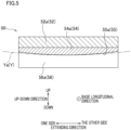
- the first heater 13 has yarn running grooves 56 extending along the extending direction as shown in FIG. 5 .
- the first heater 13 is configured to heat each yarn Y running from the other side to one side in the extending direction in the yarn running groove 56.
- the first heater 13 is configured to be able to heat two yarns Y (yarns Ya and Yb; see FIG. 4 ).
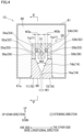
- the first heater 13 mainly includes a heating unit 50, a housing 61, a heat insulator 70, and guiders 81 and 85, as shown in FIGs. 4 , 6 , and 7 .
- the heating unit 50 two yarn running grooves 56 (56a and 56b) are formed to extend in the extending direction.
- the arrangement direction of the two yarn running grooves 56 is the base longitudinal direction (equivalent to a second direction of the present invention).
- the heating unit 50 heats the yarns Y (yarns Ya and Yb) running in the yarn running grooves 56 (56a and 56b) .
- the heat insulator 70 is provided below the heating unit 50 (yarn running grooves 56).
- the housing 61 accommodates the heating unit 50 and the heat insulator 70 therein.
- the guiders 81 and 85 are attached to the housing 61.
- the heating unit 50 mainly includes a heat source 51, two heating blocks 52 (52a and 52b), and two yarn contacted portions 54 (54a and 54b).
- the heating unit 50 extends along the extending direction.
- the heat source 51 is, for example, a sheathed heater.
- the heat source 51 extends along the extending direction.
- the heating blocks 52 and the yarn contacted portion 54 are configured to be heated by heat generated by the heat source 51.
- the heating blocks 52 and the yarn contacted portion 54 extend in the extending direction along the heat source 51.
- the heating block 52a and the yarn contacted portion 54a are members for heating the yarn Ya.
- the heating block 52b and the yarn contacted portion 54b are members for heating the yarn Yb.
- the members configured to heat the yarn Ya oppose the members configured to heat the yarn Yb over the heat source 51 in the base longitudinal direction.
- the heating block 52a is made of a metal material such as brass in which the specific heat is high.
- the heating block 52a is provided to be in contact with the heat source 51.
- the heating block 52a is provided on one side in the base longitudinal direction of the heat source 51 (on the left side of the sheet of FIG. 4 ).
- the heating block 52a has a yarn running groove 56a extending in the extending direction. In the present embodiment, the entire yarn running groove 56a is defined by the heating block 52a.
- the yarn running groove 56a is open at the bottom end face (lower surface) of the heating block 52a. That is to say, the bottom end of the yarn running groove 56a is an open end.
- the yarn contacted portion 54a is accommodated in the yarn running groove 56a.
- the yarn contacted portion 54a is, for example, a long member made of SUS.
- the yarn contacted portion 54a is fixed to the heating block 52a while being in contact with the heating block 52a.
- the yarn contacted portion 54a is heated by the heat which is transmitted from the heat source 51 via the heating block 52a, with the result that the temperature of the yarn contacted portion 54a is increased.
- the yarn contacted portion 54a includes a yarn contact surface 55 (55a) with which the yarn Y makes contact.
- the yarn contact surface 55a faces down.
- the yarn contact surface 55a is, as shown in FIG. 5 , substantially U-shaped and curved convexly downward in a cross section orthogonal to the base longitudinal direction.
- the yarn contact surface 55a is curved in an upside-down U shape that bulges upward when viewed in the extending direction, as shown in FIG. 4 .
- the heating block 52b is provided on the other side in the base longitudinal direction of the heat source 51 (on the right side of the sheet of FIG. 4 ).
- the heating block 52b is in contact with the heat source 51.
- the heating block 52b has a yarn running groove 56b formed with the same shape as the yarn running groove 56a.
- a yarn contacted portion 54b which has the same structure as the yarn contacted portion 54a is accommodated.
- the yarn contacted portion 54b includes a yarn contact surface 55b which is identical in shape with the yarn contact surface 55a. Further details are omitted.
- the yarns Y (Ya and Yb) introduced into the first heater 13 run in the yarn running grooves 56 (56a and 56b) while being in contact with the yarn contact surfaces 55 (55a and 55b). This allows the yarns Y (Ya and Yb) to receive heat from the heating blocks 52 (52a and 52b) through the yarn contact surfaces 55 (55a and 55b) and to be heated.
- the temperature of each yarn Y is increased to an appropriate processing temperature by properly setting the type, brand (thickness), and running speed of the yarn Y and the heating temperature.
- the housing 61 is a roughly cuboid in shape with the extending direction being the longitudinal direction. As described above, the housing 61 accommodates the heating unit 50 and the heat insulator 70 therein. As shown in FIG. 4 , a heat insulating material 90 is provided to fill the space between the inner wall surface of housing 61 and the heating unit 50 and the heat insulator 70 accommodated in the housing 61.
- the heat insulating material 90 for example, is made of a material such as rock wool or ceramic fiber.
- An opening 68 is formed in a lower wall 61a which is the lower side wall of the housing 61.
- the opening 68 is formed across the entire length of the housing 61 in the extending direction.
- openings 69 are formed in both side walls 61b and 61c that are on the respective sides in the extending direction of the housing 61. Each opening 69 is open downward.
- the heat insulator 70 is composed of two heat insulating blocks 71 and 72.
- the heat insulating blocks 71 and 72 are made of a material such as plaster board, for example.
- the heat insulating blocks 71 and 72 both extend along the extending direction.
- the heat insulating blocks 71 and 72 are lined up along the base longitudinal direction.
- the heat insulating blocks 71 and 72 are attached to the housing 61 in a detachable manner.
- the heat insulating blocks 71 and 72 are provided on the opposite side of the yarn running grooves 56a and 56b over the bottom ends of the yarn running grooves 56a and 56b, which are open ends.
- the heat insulating block 71 is provided below the yarn running groove 56a.
- the heat insulating block 72 is provided below the yarn running groove 56b.
- the heat insulating blocks 71 and 72 are placed in a region opposing the opening 68 formed in the lower wall 61a of the housing 61 in the up-down direction.
- the heat insulating blocks 71 and 72 are placed in a region opposing the openings 69 formed in the side walls 61b and 61c of the housing 61 in the extending direction.
- a gap is formed between the heat insulating blocks 71 and 72 in the base longitudinal direction.
- the gap between heat insulating blocks 71 and 72 constitutes a yarn guide passage 74.
- the yarn guide passage 74 allows the yarns Ya and Yb to pass therethrough.
- the yarn guide passage 74 is a passage through which the yarns Ya and Yb are inserted into the respective two yarn running grooves 56a and 56b when yarn threading to the first heater 13 is performed.
- the entirety of the yarn guide passage 74 serves as a common passage for the two yarn running grooves 56a and 56b. That is, the yarns Ya and Yb inserted into the two yarn running grooves 56a and 56b respectively pass through the yarn guide passage 74 from one end (lower end) to the other end (upper end).
- the yarn guide passage 74 has a narrow portion 74a and a wide portion 74b.
- the narrow portion 74a extends upward along the heat insulating blocks 71 and 72 from the lower end portion.
- the wide portion 74b corresponds to a portion on the yarn running groove 56 side of the narrow portion 74a (i.e., above the narrow portion 74a) in the up-down direction.
- the width (in the base longitudinal direction) W1 of the narrow portion 74a is constant in the up-down direction.
- the width W1 of the narrow portion 74a is narrower than the total width (W3a+W3b) of the width W3a (in the base longitudinal direction) of the yarn running groove 56a and the width W3b (in the base longitudinal direction) of the yarn running groove 56b.
- the widths of the yarn running grooves 56a and 56b are constant in the up-down direction.
- the above-described width W3a of the yarn running groove 56a is defined as the width of the opening (lower end portion) of the yarn running groove 56a
- the above-described width W3b of the yarn running groove 56b is defined as the width of the opening (lower end portion) of the yarn running groove 56b.
- the length along the up-down direction of the narrow portion 74a is 20mm or more.
- the width W2 (in the base longitudinal direction) of the wide portion 74b increases toward the yarn running groove 56 (i.e., upward).
- An end portion (upper end portion) of the wide portion 74b on the yarn running groove 56 side opposes both of the two yarn running grooves 56a and 56b. More specifically, the end portion of the wide portion 74b on the yarn running groove 56 side opposes the entirety of the open end of each of the yarn running groove 56a and 56b.
- the guider 81 is attached to a side wall 61b on one side in the extending direction of the housing 61, as shown in FIG. 6 .
- the guider 85 is attached to a side wall 61c on the other side in the extending direction of the housing 61, as shown in FIG. 7 .
- the guiders 81 and 85 are provided on the respective sides of the heat insulator 70 in the extending direction.
- a slit 82 is formed in the guider 81.
- the slit 82 guides yarns Y when inserting the yarns Ya and Yb into the respective yarn running grooves 56a and 56b through the yarn guide passage 74.
- the slit 82 has an inlet section 83 and two branching sections 84a and 84b.
- the inlet section 83 is shared between the two yarn running grooves 56a and 56b.
- the inlet section 83 extends in the up-down direction.
- the inlet section 83 is provided at a position facing the narrow portion 74a of the yarn guide passage 74 in the extending direction.
- the inlet section 83 guides the yarn Y passing through the narrow portion 74a of the yarn guide passage 74.
- the two branching sections 84a and 84b branch toward the respective sides in the base longitudinal direction from the upper end portion of the inlet section 83.
- the branching section 84a guides the yarn Ya to the yarn running groove 56a.
- the branching section 84b guides the yarn Yb to the yarn running groove 56b.
- the guider 81 is composed of two side plates 81a and 81b and a central plate 81c.
- the side plate 81a is attached to a portion on one side (left side on the sheet of FIG. 6 ) in the base longitudinal direction of the opening 69 in the side wall 61b of the housing 61.
- the side plate 81b is attached to a portion on the other side (right side on the sheet of FIG. 6 ) in the base longitudinal direction of the opening 69 in the side wall 61b of the housing 61.
- Both of the side plates 81a and 81b are arranged to partially cover opening 69.
- the side plates 81a and 81b are arranged to be spaced apart from each other in the base longitudinal direction.
- the central plate 81c is attached to an upper part of the opening 69 in the side wall 61b of the housing 61.
- the central plate 81c is arranged to partially close the opening 69.
- the central plate 81c is provided between upper parts of the side plates 81a and 81b in the base longitudinal direction.
- the central plate 81c is arranged to be spaced apart from the side plates 81a and 81b in the base longitudinal direction.
- a gap between lower parts of side plates 81a and 81b serves as the inlet section 83 of the slit 82.
- a gap between the upper part of the side plate 81a and the central plate 81c serves as the branching section 84a of the slit 82.
- a gap between the upper part of the side plate 81b and the central plate 81c serves as the branching section 84b of the slit 82.
- the side plates 81a and 81b extend to reach a position below the lower end portion of the heat insulator 70. That is, the inlet section 83, which is formed by the gap between the side plates 81a and 81b, extends to reach a position below the lower end portion of the heat insulator 70.
- the lower end portions of the side plates 81a and 81b are provided with notches 81a1 and 81b1, respectively.
- the notches 81a1 and 81b1 are provided on the respective sides of the inlet section 83 of the slit 82 in the base longitudinal direction.
- a slit 86 equivalent to the slit 82 of the guider 81 is formed in the guider 85.
- the slit 86 therefore has an inlet section 87 and two branching sections 88a and 88b.
- the inlet section 87 is shared between the two yarn running grooves 56a and 56b.
- the branching sections 88a and 88b guide the yarns Ya and Yb to the yarn running grooves 56a and 56b, respectively.
- the guider 85 is composed of two side plates 85a and 85b and a central plate 85c.
- a gap between lower parts of side plates 85a and 85b serves as the inlet section 87 of the slit 86.
- Gaps between the upper parts of the side plates 85a and 85b and the central plate 85c serve as the branching sections 88a and 88b of the slit 86.
- the side plates 85a and 85b extend to reach a position below the lower end portion of the heat insulator 70.
- the inlet section 87 of the slit 86 has an extension portion 87a that extends to reach the side that is opposite to the heating unit 50 over the heat insulator 70 in the up-down direction.
- the width W4 in the base longitudinal direction of the extension portion 87a increases away from the heating unit 50 (i.e., increases downward).
- the pair of false-twisting devices 15 to which the two yarns Ya and Yb are threaded are equivalent to a first yarn path formation device of the present invention.
- the pair of false-twisting devices 15 are capable of supporting the two yarns Y to be runnable.
- a false-twisting device 15 is capable of simultaneously twisting two yarns Y
- one false-twisting device 15 is equivalent to the first yarn path formation device of the present invention.
- a pair of twist-stopping guides 12, to which the two yarns Ya and Yb are threaded are equivalent to a second yarn path formation device of the present invention.
- the pair of twist-stopping guides 12 are capable of supporting the two yarns Y to be runnable.
- a twist-stopping guides 12 is provided for each pair of two yarns Y, one twist-stopping guide 12 is equivalent to the second yarn path formation device of the present invention.
- the false-twisting device 15 which is provided on one side (the left side on the sheet of FIG. 8 ) of the first heater 13 in the extending direction, supports the yarn Y at a position above the lower end portion of the first heater 13 in the up-down direction.
- the twist-stopping guide 12, which is on the other side (the right side on the sheet in FIG. 8 ) of the first heater 13 in the extending direction, is arranged to be movable in the up-down direction by a driving mechanism (not illustrated).
- the twist-stopping guide 12 is movable in the up-down direction between a heating position (shown in FIG. 8(b) ) and a retracted position (shown in FIG. 8(a) and FIG. 10(a) ).
- the twist-stopping guide 12 When the twist-stopping guide 12 is positioned at the heating position, the yarn path formed between the twist-stopping guide 12 and the false-twisting device 15 extends substantially in the extending direction in the yarn running groove 56.
- the twist-stopping guide 12 descends from the heating position to the retracted position. To put it differently, the retracted position is below the heating position. As shown in Figure 10(a) , the retracted position is on the side opposite to the yarn running groove 56 over the inlet section 87 of the slit 86 formed in the guider 85 in the up-down direction.
- the yarn paths of the two yarns Ya and Yb formed by the pair of twist-stopping guides 12 and the pair of false-twisting devices 15 are located on the respective sides of the inlet section 83 of the slit 82 formed in the guider 81 in the base longitudinal direction, when viewed in the extending direction. Furthermore, the yarn paths of the two yarns Ya and Yb, which are formed by the pair of twist-stopping guides 12 at the retracted positions and the pair of false-twisting devices 15, pass through the notches 81a1 and 81b1 formed in the lower end portions of the side plates 81a and 81b constituting the guider 81. Therefore, as shown in FIG.
- the operator inserts the two yarns Ya and Yb held by the notches 81a1 and 81b1 into the respective yarn running grooves 56a and 56b through the yarn guide passage 74, while the yarns Ya and Yb are guided by the slit 82.
- the yarn paths of the two yarns Ya and Yb are located on the respective sides of the inlet section 83 of the slit 82 in the base longitudinal direction. Therefore, as shown in FIG. 9(b) , when the yarn Ya passes through the inlet section 83 of the slit 82, the yarn Ya is pulled towards the outside of the slit 82 (i.e., toward one side in the longitudinal direction of the base; toward the left side on the sheet).
- the yarn Ya After the yarn Ya passes through the inlet section 83, the yarn Ya is guided through the branching section 84a to the yarn running groove 56a. Furthermore, as shown in FIG. 9(c) , when the yarn Yb passes through the inlet section 83 of the slit 82, the yarn Yb is pulled towards the outside of the slit 82 (i.e., toward the other side in the longitudinal direction of the base; toward the right side on the sheet). After the yarn Yb passes through the inlet section 83, the yarn Yb is guided through the branching section 84b to the yarn running groove 56b.
- the pair of twist-stopping guides 12 are raised to the heating position.
- the extension portion 87a of the slit 86 formed in the guider 85 provided on the other side of the heat insulator 70 in the extending direction is positioned on a movement trace along which the two yarns Ya and Yb supported by the pair of twist-stopping guides 12 move when the twist-stopping guides 12 are moved up from the retracted position to the heating position. Therefore, as shown in FIG.
- the heat insulator 70 is configured to be detachable from the housing 61. Therefore, when yarn breakage occurs, the removal of the yarn Y from the first heater 13 can be performed in a state where the heat insulator 70 has been detached from the housing 61, as shown in FIG. 11 .
- FIG.12 is a graph showing the power consumption when the yarn guide passages of the comparative example and the example were employed and a set temperature of the heating unit was set at 250 degrees centigrade.
- the graph in FIG. 12 shows that the power consumption decreases as the length of the narrow portion increases.
- the length of the narrow portion is 7mm, the power consumption is significantly high as compared to cases where the length of the narrow portion is not 7mm. Therefore, in consideration of the reduction of the power consumption, the length of the narrow portion is preferably 20mm or more.
- the first heater 13 further includes the heating unit 50 which extends along the extending direction and is configured to heat the yarns Ya and Yb running in the yarn running grooves 56a and 56b and the heat insulator 70 which extends in the extending direction and is provided to be opposite to the yarn running grooves 56a and 56b over the open ends of the yarn running grooves 56a and 56b in the up-down direction.
- the yarn guide passage 74 is formed to allow the yarns Ya and Yb to pass through, in order to insert the yarns Ya and Yb into the respective yarn running grooves 56a and 56b.
- the yarn guide passage 74 is entirely a common passage shared between the yarn running grooves 56a and 56b.
- the yarn guide passage 74 has a narrow portion 74a formed as part of a common passage and having a width W1 that is narrower than the sum of the widths (W3a+W3b) of the two yarn running grooves 56a and 56b.
- the yarn guide passage 74 serves as a common passage for the two yarn running grooves 56a and 56b.
- the yarn guide passage 74 has the narrow portion 74a that is narrower than the sum of the widths of the two yarn running grooves 56a and 56b.
- the length of the narrow portion 74a of the yarn guide passage 74 in the up-down direction is 20mm or more. Because the narrow portion 74a is sufficiently long, circulation of air through the narrow portion 74a is suppressed. On this account, it is possible to further reliably suppress the inflow and outflow of air to and from the yarn running grooves 56a and 56b through the yarn guide passages 74. This further reduces the power consumption.
- the heat insulator 70 is detachable from the housing 61. Because the yarn guide passage 74 serves as a common passage for the two yarn running grooves 56a and 56b, the heat insulator 70 in which the yarn guide passage 74 is formed becomes an obstacle to remove the yarn Y when yarn breakage occurs. In this configuration, the removal of the yarn Y becomes easy by detaching the heat insulator 70 in which the yarn guide passage 74 is formed.
- the yarn guide passage 74 has the wide portion 74b having a width W2 that increases toward the yarn running grooves 56a and 56b.
- the wide portion 74b corresponds to a portion on the yarn running grooves 56a and 56b side of the narrow portion 74a in the up-down direction, and an end portion on the yarn running grooves 56a and 56b side of the wide portion 74b opposes both of the two yarn running grooves 56a and 56b.
- the yarns Ya and Yb can be easily inserted into the respective two yarn running grooves 56a and 56b.
- the first heater 13 of the present embodiment further includes the guiders 81 and 85 that are arranged on the respective sides of the heat insulator 70 in the extending direction.
- the slits 82 and 86 are formed, respectively, in order to guide the yarns Ya and Yb when the yarns Ya and Yb are inserted into the respective two yarn running grooves 56a and 56b through the yarn guide passage 74.
- the slit 82 includes the inlet section 83 which is shared between the two yarn running grooves 56a and 56b and two branching sections 84a and 84b which are branched from the inlet section 83 and guide the respective yarns Ya and Yb to the two yarn running grooves 56a and 56b.
- the slit 86 includes the inlet section 87 which is shared between the two yarn running grooves 56a and 56b and two branching sections 88a and 88b which are branched from the inlet section 87 and guide the respective yarns Ya and Yb to the two yarn running grooves 56a and 56b.
- the inlet sections 83 and 87 of the slits 82 and 86 formed in the guiders 81 and 85 are shared between the two yarn running grooves 56a and 56b. Due to this, the guiders 81 and 85 suppress the circulation of air through the end portion of the yarn guide passage 74 in the extending direction, so as to reliably suppress the inflow and outflow of the air to and from the yarn running grooves 56a and 56b. Therefore, the power consumption is further reduced.
- the false-twist texturing machine 1 of the present embodiment includes the false-twisting devices 15 that are positioned on one side of the first heater 13 in the extending direction and the twist-stopping guides 12 that are positioned on the other side of the first heater 13 in the extending direction.
- the two yarn paths formed by the pair of false-twisting devices 15 and the pair of twist-stopping guides 12 are located on the respective sides of the inlet section 83 of the slit 82 formed in the guider 81 in the base longitudinal direction, when viewed in the extending direction.
- the twist-stopping guide 12 is arranged to be movable in the up-down direction.
- the twist-stopping guide 12 is movable between the heating position and the retracted position.
- the heating position is a position where the yarn path formed between the twist-stopping guide 12 and the false-twisting device 15 extends along the extending direction in the yarn running groove 56a, 56b.
- the retracted position is a position that is on the opposite side in the up-down direction of the yarn running groove 56a, 56b over the inlet section 87 of the slit 86 formed in the guider 85.
- the inlet section 87 of the slit 86 formed in the guider 85 has the extension portion 87a that extends to reach the side that is opposite to the heating unit 50 over the heat insulator 70 in the up-down direction.
- the width W4 in the base longitudinal direction of the extension portion 87a increases away from the heating unit 50.
- the number of yarn running grooves 56 is at least two, and may be three or more.
- the heat insulator 70 is composed of the two heat insulating blocks 71 and 72, the disclosure is not limited to this arrangement.
- the heat insulator 70 may be composed of three or more heat insulating blocks. It is noted that, when the heat insulator 70 is composed of three or more heat insulating blocks, a gap between two of these heat insulating blocks constitutes a yarn guide passage 74 that includes a common passage shared by at least two yarn running grooves 56.
- common passage (yarn guide passage 74) is shared between the two yarn running grooves 56, the disclosure is not limited to this arrangement.
- the common passage may be shared between three or more yarn running grooves 56.
- the disclosure is not limited to this arrangement.
- the heat insulator 70 may not be detachable.
- the yarn guide passage 74 has the wide portion 74b having a width that increases toward the yarn running groove 56, the disclosure is not limited to this arrangement.
- the yarn guide passage 74 may have a constant width in the up-down direction.
- the disclosure is not limited to this arrangement.
- the end portion on the yarn running groove 56 side of the wide portion 74b may oppose only one of the two yarn running grooves 56.
- the yarn running groove 56 opposing the end portion on the yarn running groove 56 side of the wide portion 74b may oppose that end portion only at a part of the open end.
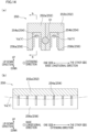
- the first heater 113 includes a partition member 173 that divides the yarn guide passage 74 into individual passages 175a and 175b corresponding to the respective two yarn running grooves 56a and 56b in the wide portion 74b of the yarn guide passage 74.
- the partition member 173 is made of a heat insulating material.
- the partition member 173 is formed of, for example, plaster board.
- the partition member 173 extends along the extending direction.
- the wide portion 74b is partitioned by the partition member 173 into the individual passages 175a and 175b.
- the individual passage 175a is a passage through which the yarn Ya is sent to the yarn running groove 56a.
- the individual passage 175b is a passage through which the yarn Yb is sent to the yarn running groove 56b.
- the narrow portion 74a of the yarn guide passage 74 serves as a common passage for the two yarn running grooves 56a and 56b. While in the embodiment above a part of the common passage is the narrow portion 74a, the entirety of the common passage is the narrow portion 74a in this modification. While in the embodiment above the entirety of the yarn guide passage 74 serves as the common passage, only at least part of the yarn guide passage 74 is required to serve as a common passage as in this modification.
- the wide portion 74b may be divided to correspond to the three or more yarn running grooves 56 by two or more partition members 173.
- the yarn running groove 56 may be formed at least partially in the heating unit 50. That is to say, for example, the bottom surface of the yarn running groove 56 may be defined by the heating block 52, and the side surfaces of the yarn running groove 56 may be defined by a member other than the heating block 52 (a member other than the members constituting the heating unit 50).
- plural yarn guides 254 are aligned along the extending direction in yarn running grooves 256. More specifically, plural yarn guides 254a are provided in yarn running grooves 256a. Plural yarn guides 254b are provided in yarn running grooves 256b.
- the heating unit 250 is a contactless heating unit configured to heat the yarn Y by heated air.
- the heating temperature is relatively high.
- the heating temperature of the heating unit 50 of the embodiment above is approximately 350 degrees centigrade
- the heating temperature of the heating unit 250 of this modification is approximately 600 degrees centigrade. In this configuration, it is possible to suppress the release of air heated by the heating unit 250 having a relatively high heating temperature to the outside. Due to this, the power consumption is effectively reduced.
- the heating unit 50 includes the heat source 51 and the heating block 52 heated by the heat source 51, the disclosure is not limited to this arrangement.
- the heating unit may have a structure in which a heating medium such as Dowtherm circulates inside a hollow member.
- guiders 81 and 85 are provided on the respective sides of the heat insulator 70 in the extending direction, the disclosure is not limited to this arrangement.
- the guiders 81 and 85 may be provided only on one side of the heat insulator 70 in the extending direction.
- the guiders 81 and 85 may not be provided.
- the slits 82 and 86 formed in the guiders 81 and 85 have paired branching sections 84a, 84b, 88a, and 88b by which the yarns Y are guided to the two yarn running grooves 56, the disclosure is not limited to this arrangement.
- Each of the slits 82 and 86 may have three or more branching sections.
- the two yarn paths formed by the pair of false-twisting devices 15 and the pair of twist-stopping guides 12 are located on the respective sides of the inlet section 83 of the slit 82 formed in the guider 81 in the base longitudinal direction, when viewed in the extending direction.
- the disclosure is not limited to this arrangement.
- the two yarn paths formed by the pair of false-twisting devices 15 and the pair of twist-stopping guides 12 may be provided on the inner side of the inlet section 83 in the base longitudinal direction, when viewed in the extending direction.
- the members constituting the two yarn paths on the outer side of the inlet section 83 in the base longitudinal direction when viewed in the extending direction are not limited to the pair of false-twisting devices 15 and the pair of twist-stopping guides 12.
- the yarn paths are only required to be able to support the two yarns Y in a runnable manner and to be formed of a member provided on one side of the first heater 13 in the extending direction and a member provided on the other side of the first heater 13 in the extending direction.
- twist-stopping guide 12 While in the embodiment above the twist-stopping guide 12 is movable in the up-down direction, the disclosure is not limited to this arrangement.
- the twist-stopping guide 12 may be positionally fixed in the up-down direction. When the twist-stopping guide 12 is positionally fixed, yarn threading to the twist-stopping guide 12 is performed by using a yarn threading rod.
- the inlet section 87 of the slit 86 formed in the guider 85 includes the extension portion 87a having a width that increases away from the heating unit 50, the disclosure is not limited to this arrangement.
- the inlet section 87 of the slit 86 may not include the extension portion 87a.
- the yarn heater of the present invention is applied to the false-twist texturing machine 1 configured to false-twist the yarns Y.
- the yarn heater of the present invention is applicable to a processor configured to perform, for yarns formed of synthetic fibers, various processes such as yarn combining in addition to false twisting.
Landscapes
- Engineering & Computer Science (AREA)
- Textile Engineering (AREA)
- Mechanical Engineering (AREA)
- Yarns And Mechanical Finishing Of Yarns Or Ropes (AREA)
Abstract
Description
- The present invention relates to a yarn heater for heating yarns and a yarn processor including the yarn heater.
- A yarn heater configured to heat yarns running in a yarn processor performing various processes such as yarn combination and false twisting for synthetic fiber yarns has been known. Patent Literature 1 (
Japanese Laid-Open Patent Publication No. H1-183546 - The two yarn running grooves extend along a first direction and are aligned in a second direction orthogonal to the first direction. Each yarn running groove is open on one side in a third direction which is orthogonal to both the first direction and the second direction. The heat insulating material extends along the first direction and is attached to an end face of the heat conductor, where the yarn running grooves are open. The heat insulating material has two yarn insertion slits (yarn guide passages) which are independent from each other and are provided to insert yarns into the respective two yarn running grooves.
- In the yarn heater described above, air is introduced into and discharged from each yarn running groove through the yarn guide passage provided for each yarn running groove. As a result, the heating unit and its vicinity are not easily heated due to the outflow of warm air and the inflow of cool air, with the result that the power consumption for heating the yarns increases.
- An object of the present invention is to provide a yarn heater capable of reducing power consumption and a yarn processor.
- A yarn heater according to a first aspect of the invention is a yarn heater in which at least two yarn running grooves in which yarns run are formed, the at least two yarn running grooves being aligned in a second direction orthogonal to a first direction in which the yarn running grooves extend. The yarn heater includes: a heating unit which extends along the first direction and is configured to heat the yarns running in the at least two yarn running grooves; and a heat insulator which extends along the first direction and is provided on the opposite side of the at least two yarn running grooves over open ends of the at least two yarn running grooves in a third direction orthogonal to the first direction and the second direction. In the heat insulator, a yarn guide passage is formed to allow the yarns to pass through and to introduce the yarns into the at least two yarn running grooves, respectively, at least part of the yarn guide passage functions as a common passage shared between the at least two yarn running grooves, the yarn guide passage includes: a narrow portion which is formed as at least part of the common passage and has a width that is narrower in the second direction than a total width in the second direction of the at least two yarn running grooves; and a wide portion whose width in the second direction increases toward the at least two yarn running grooves, the wide portion is a part of the yarn guide passage on the yarn running groove side in the third direction of the narrow portion, and an end portion on the yarn running groove side of the wide portion opposing entirety of the at least two yarn running grooves, and the yarn heater further includes at least one partition member which is made of a heat insulating material, extends along the first direction, and divides the yarn guide passage into individual passages corresponding to the respective at least two yarn running grooves, at the wide portion of the yarn guide passage.
- In the present invention, at least part of the yarn guide passage is a common passage shared between the at least two yarn running grooves. The yarn guide passage has a narrow portion formed as at least part of a common passage and having a width that is narrower than the sum of the widths of the two yarn running grooves. On this account, as compared to a case where independent yarn guide passages are provided for the respective at least two yarn running grooves, it is possible to suppress the inflow and outflow of air to and from the yarn running grooves through the yarn guide passage. Therefore, the power consumption is reduced.
- According to the aspect of the present invention, because the yarns inserted into the yarn guide passage pass through the narrow portion and then pass through the wide portion opposing entirety of the at least two yarn running grooves, the yarns can be easily inserted into the respective at least two yarn running grooves.
- Furthermore, according to the aspect of the present invention, it is possible to further suppress the inflow and outflow of air to and from the yarn running groove through the yarn guide passage by the partition member. Therefore, the power consumption is reliably reduced.
- According to a second aspect of the invention, the yarn heater of the first aspect of the invention is arranged such that the length in the third direction of the narrow portion of the yarn guide passage is 20mm or more.
- According to the aspect of the present invention, because the narrow portion is sufficiently long, circulation of air through the narrow portion is suppressed. On this account, it is possible to further reliably suppress the inflow and outflow of air to and from the yarn running grooves through the yarn guide passages. Therefore, the power consumption can be further decreased.
- According to a third aspect of the invention, the yarn heater of the first or second aspect of the invention is arranged such that the heat insulator is configured to be detachable.
- Because the yarn guide passage at least partially serves as a common passage for the plural yarn running grooves, the heat insulator in which the yarn guide passage is formed becomes an obstacle to remove the yarn when yarn breakage occurs. In the present invention, the removal of the yarn becomes easy by detaching the heat insulator in which the yarn guide passage is formed.
- According to a fourth aspect of the invention, the yarn heater of any one of the first to third aspects of the invention is arranged such that the heating unit is a contactless heater by which the yarns are heated by heated air.
- In the contactless heating unit, the heating temperature is relatively high. According to the aspect of the present invention, it is possible to suppress the release of heat from the heating unit having a relatively high heating temperature to the outside. Due to this, the power consumption is effectively reduced.
- According to a fifth aspect of the invention, the yarn heater according to any one of the first to fourth aspects of the invention further includes a guider provided at least on one side in the first direction of the heat insulator, in the guider. In the guider, a slit is formed to guide the yarns when the yarns are inserted into the at least two yarn running grooves through the yarn guide passage. The slit has an inlet section which is shared between the at least two yarn running grooves and at least two branching sections which are branched from the inlet section to guide the yarns to the respective at least two yarn running grooves.
- According to this aspect of the present invention, the inlet section of the slit formed in the guider is shared between the at least two yarn running grooves. Therefore, the guider can suppress the flow of air through the end portion of the yarn guide passage in the extending direction, and can reliably suppress the inflow and outflow of air to and from the yarn running groove. Therefore, the power consumption is further reduced.
- A yarn heater according to a sixth aspect of the invention is a yarn heater in which at least two yarn running grooves in which yarns run are formed, the at least two yarn running grooves being aligned in a second direction orthogonal to a first direction in which the yarn running grooves extend. The yarn heater includes: a heating unit which extends along the first direction and is configured to heat the yarns running in the at least two yarn running grooves; a heat insulator which extends along the first direction and is provided on the opposite side of the at least two yarn running grooves over open ends of the at least two yarn running grooves in a third direction orthogonal to the first direction and the second direction; and at least one guider provided at least on one side in the first direction of the heat insulator. In the heat insulator, a yarn guide passage is formed to allow the yarns to pass through and to introduce the yarns into the at least two yarn running grooves, respectively, at least part of the yarn guide passage functions as a common passage shared between the at least two yarn running grooves, and the yarn guide passage includes a narrow portion which is formed as at least part of the common passage and has a width that is narrower in the second direction than a total width in the second direction of the at least two yarn running grooves. In the at least one guider, a slit is formed to guide the yarns when the yarns are inserted into the at least two yarn running grooves through the yarn guide passage, and the slit has an inlet section which is shared between the at least two yarn running grooves and at least two branching sections which are branched from the inlet section to guide the yarns to the respective at least two yarn running grooves.
- In the present invention, at least part of the yarn guide passage is a common passage shared between the at least two yarn running grooves. The yarn guide passage has a narrow portion formed as at least part of a common passage and having a width that is narrower than the sum of the widths of the two yarn running grooves. On this account, as compared to a case where independent yarn guide passages are provided for the respective at least two yarn running grooves, it is possible to suppress the inflow and outflow of air to and from the yarn running grooves through the yarn guide passage. Therefore, the power consumption is reduced.
- According to the aspect of the present invention, furthermore, the inlet section of the slit formed in the guider is shared between the at least two yarn running grooves. Therefore, the guider can suppress the flow of air through the end portion of the yarn guide passage in the extending direction, and can reliably suppress the inflow and outflow of air to and from the yarn running groove. Therefore, the power consumption is further reduced.
- According to a seventh aspect of the invention, the yarn heater of the sixth aspect of the invention is arranged such that the length in the third direction of the narrow portion of the yarn guide passage is 20mm or more.
- According to the aspect of the present invention, because the narrow portion is sufficiently long, circulation of air through the narrow portion is suppressed. On this account, it is possible to further reliably suppress the inflow and outflow of air to and from the yarn running grooves through the yarn guide passages. Therefore, the power consumption can be further decreased.
- According to an eighth aspect of the invention, the yarn heater of the sixth or seventh aspect of the invention is arranged such that the heat insulator is configured to be detachable.
- Because the yarn guide passage at least partially serves as a common passage for the plural yarn running grooves, the heat insulator in which the yarn guide passage is formed becomes an obstacle to remove the yarn when yarn breakage occurs. In the present invention, the removal of the yarn becomes easy by detaching the heat insulator in which the yarn guide passage is formed.
- According to a ninth aspect of the invention, the yarn heater of any one of the sixth to eighth aspects of the invention is arranged such that the yarn guide passage further includes a wide portion whose width in the second direction increases toward the at least two yarn running grooves, and the wide portion is a part of the yarn guide passage on the yarn running groove side in the third direction of the narrow portion and an end portion on the yarn running groove side of the wide portion opposing entirety of the at least two yarn running grooves.
- According to the aspect of the present invention, because the yarns inserted into the yarn guide passage pass through the narrow portion and then pass through the wide portion opposing entirety of the at least two yarn running grooves, the yarns can be easily inserted into the respective at least two yarn running grooves.
- According to a tenth aspect of the invention, the yarn heater of the ninth aspect of the invention further includes at least one partition member which is made of a heat insulating material, extends along the first direction, and divides the yarn guide passage into individual passages corresponding to the respective at least two yarn running grooves, at the wide portion of the yarn guide passage.
- According to the aspect of the present invention, it is possible to further suppress the inflow and outflow of air to and from the yarn running groove through the yarn guide passage by the partition member. Therefore, the power consumption is reliably reduced.
- According to an eleventh aspect of the invention, the yarn heater of any one of the sixth to tenth aspects of the invention is arranged such that the heating unit is a contactless heater by which the yarns are heated by heated air.
- In the contactless heating unit, the heating temperature is relatively high. According to the aspect of the present invention, it is possible to suppress the release of heat from the heating unit having a relatively high heating temperature to the outside. Due to this, the power consumption is effectively reduced.
- According to a twelfth aspect of the invention, a yarn processor configured to process yarns includes: the yarn heater according to any one of the fifth to eleventh aspects of the invention, in which two yarn running grooves are formed; a first yarn path formation device which is able to support two yarns to be runnable and is provided on the one side in the first direction of the yarn heater; and a second yarn path formation device which is able to support two yarns to be runnable and is provided on the other side in the first direction of the yarn heater, the other side being opposite to the one side. The two yarn paths formed by the first yarn path formation device and the second yarn path formation device are on the respective sides of the inlet section of the slit in the second direction, when viewed in the first direction.
- According to this aspect of the present invention, when the yarns pass through the inlet section of the slit, the yarns are pulled in the second direction towards the outside of the slit. This allows each of the two yarns to move toward the branching section that is close to the yarn path of that yarn in the second direction. On this account, it is possible to prevent each of the two yarns from passing through a branching section that the each yarn is not supposed to pass, and to prevent each of the yarns from being guided to an erroneous yarn running groove.
- According to a thirteenth aspect of the invention, the yarn processor of the twelfth aspect of the invention is arranged such that the guiders are provided on the respective sides of the heat insulator in the first direction. The second yarn path formation device is movable in the third direction between a heating position where yarn paths formed between the second yarn path formation device and the first yarn path formation device extend along the first direction in the at least two yarn running grooves and a retracted position which is on the opposite side of the at least two yarn running grooves over the inlet section of the slit in the third direction. The inlet section of the slit formed in the guiders on the opposite side of the heat insulator in the first direction includes an extension portion which extends to reach the side opposite to the heating unit over the heat insulator in the third direction, and the width in the second direction of the extension portion increases away from the heating unit.
- According to this aspect of the present invention, as the second yarn path formation device is moved from the retracted position to the heating position by the extension portion, the two yarns supported by the second yarn path formation device are reliably guided to the inlet section of the slit.
-
-
FIG. 1 is a side view of a false-twist texturing machine according to an embodiment of the present invention. -
FIG. 2 is a schematic diagram of the false-twist texturing machine, expanded along paths of yarns. -
FIG. 3 illustrates a first heater. -
FIG. 4 is a cross section of the first heater cut along a line IV-IV shown inFIG. 3 . -
FIG. 5 is a cross section of a heating unit cut along a line V-V shown inFIG. 4 . -
FIG. 6 shows a state in which the first heater shown inFIG. 3 is viewed from one side in an extending direction. -
FIG. 7 shows a state in which the first heater shown inFIG. 3 is viewed from the other side in the extending direction. -
FIG. 8(a) and FIG. 8(b) explain steps of yarn threading to the first heater.FIG. 8(a) shows a state where a twist-stopping guide is at a retracted position, whereasFIG. 8(b) shows a state where the twist-stopping guide is at a heating position. -
FIG. 9(a) to FIG. 9(c) show actions of the yarns when yarn threading to the first heater is performed, when viewed from one side in the extending direction.FIG. 9(a) shows a state in which the yarns are held by notches.FIG. 9(b) shows an action of the yarn when one of the yarns is inserted.FIG. 9(c) shows an action of the yarn when the other of the yarns is inserted. -
FIG. 10 (a) and FIG. 10 (b) show actions of the yarns when yarn threading to the first heater is performed, when viewed from the other side in the extending direction.FIG. 10(a) shows a state in which the twist-stopping guide is at the retracted position.FIG. 10(b) shows a state in which the twist-stopping guide is moving from the retracted position to the heating position. -
FIG. 11 shows a state in which the heat insulator has been removed. -
FIG. 12 is a graph of power consumption when each of yarn guide passages of a comparative example and an example is employed. -
FIG. 13 shows a first heater of a first modification. -
FIGs. 14(a) and 14(b) show a heating unit of a second modification.FIG. 14(a) is a cross taken along a plane orthogonal to the extending direction, whereasFIG. 14(b) is a cross section cut along a line b-b inFIG. 14(a) . - A false-
twist texturing machine 1 of a preferred embodiment of the present invention will be described with reference toFIG. 1 . A vertical direction to the sheet ofFIG. 1 is defined as a base longitudinal direction, and a left-right direction to the sheet is defined as a base width direction. A direction orthogonal to both the base longitudinal direction and the base width direction is defined as an up-down direction in which the gravity acts. In this regard, the base longitudinal direction and the base width direction are substantially in parallel to the horizontal direction. - The false-
twist texturing machine 1 can perform false twisting of yarns Y made of, for example, synthetic fibers such as nylon (polyamide fibers) and polyester. The false-twist texturing machine 1 includes ayarn supplying unit 2 for supplying the yarns Y, aprocessing unit 3 which performs the false twisting of the yarns Y supplied from theyarn supplying unit 2, and a windingunit 4 which winds the yarns Y processed by theprocessing unit 3 onto a winding bobbins Bw. Components of theyarn supplying unit 2, theprocessing unit 3, and the windingunit 4 are aligned to form plural lines (seeFIG. 2 ) in the base longitudinal direction. The base longitudinal direction is a direction orthogonal to a running plane (plane ofFIG. 1 ) of the yarns Y, which is formed by a yarn path extending from theyarn supplying unit 2 to the windingunit 4 through theprocessing unit 3. - The
yarn supplying unit 2 includes acreel stand 5 retaining yarn supply packages Ps. Theyarn supplying unit 2 supplies multiple yarns Y to theprocessing unit 3. Theprocessing unit 3 false-twists a yarn Y supplied from a yarn supply package Ps. In theprocessing unit 3, the following members are provided in this order from the upstream in a yarn running direction:first feed rollers 11; a twist-stoppingguide 12; a first heater 13 (equivalent to a yarn heater of the present invention); a cooler 14; a false-twistingdevice 15;second feed rollers 16; an interlacingdevice 17;third feed rollers 18; asecond heater 19; andfourth feed rollers 20. The windingunit 4 includes a plurality of windingdevices 21. Each windingdevice 21 winds a corresponding yarn Y which has been false-twisted by theprocessing unit 3 onto a winding bobbin Bw and forms a wound package Pw. - The false-
twist texturing machine 1 includes amain base 8 and a windingbase 9 which are placed to be spaced apart from each other in the base width direction. Themain base 8 and the windingbase 9 are provided to extend in the base longitudinal direction and to be substantial identical in length. Themain base 8 and the windingbase 9 are arranged to face each other in the base width direction. An upper part of themain base 8 is connected to an upper part of the windingbase 9 by a supportingframe 10. Each device forming theprocessing unit 3 is mainly attached to themain base 8 or the supportingframe 10. Each device forming the windingunit 4 is attached to the windingbase 9. Themain base 8, the windingbase 9, and the supportingframe 10 form a working space A in which an operator performs an operation such as yarn threading to each device. The yarn paths are formed so that the yarns Y are able to run mainly around the working space A. - The false-
twist texturing machine 1 includes units which are termed spans each of which includes a pair of themain base 8 and the windingbase 9 placed to oppose each other. In one span, processing units (which are also termed spindles) in which yarn paths are formed to pass the devices constituting theprocessing unit 3 are lined up in the base longitudinal direction. With this arrangement, in one span, yarns Y running while being lined up in the base longitudinal direction can be simultaneously false-twisted. In the false-twist texturing machine 1, the spans are placed in a left-right symmetrical manner to the sheet, with a center line C of the base width direction of themain base 8 being a symmetry axis. Themain base 8 is shared between the left span and the right span. - The structure of the
processing unit 3 will be described with reference toFIG. 1 andFIG. 2 . Thefirst feed rollers 11 are configured to unwind a yarn Y from a yarn supply package Ps attached to theyarn supplying unit 2, and to feed the yarn Y to thefirst heater 13. As shown inFIG. 2 , for example, thefirst feed rollers 11 are configured to feed one yarn Y to thefirst heater 13. Thefirst feed rollers 11 may be able to feed adjacent yarns Y to the downstream side in the yarn running direction. In the present embodiment, a twist-stoppingguide 12 is provided for each yarn Y. The twist-stoppingguide 12 may be provided for each pair of two yarns Y. The twist-stoppingguide 12 is provided to prevent twist of the yarn Y formed by the false-twistingdevice 15 from being propagated to the upstream in the yarn running direction of the twist-stoppingguide 12. - The
first heater 13 is configured to heat the yarns Y supplied from thefirst feed rollers 11 to a predetermined processing temperature. As shown inFIG. 2 , for example, thefirst heater 13 is able to heat two yarns Y. Thefirst heater 13 will be detailed later. - The cooler 14 is configured to cool the yarn Y heated by the
first heater 13. As shown inFIG. 2 , for example, the cooler 14 is configured to cool one yarn Y. The cooler 14 may be able to simultaneously cool plural yarns Y. - The false-twisting
device 15 is placed downstream of the cooler 14 in the yarn running direction. The false-twistingdevice 15 is arranged to twist the yarn Y. The false-twistingdevice 15 is, for example, a so-called disc-friction false-twisting device, but the disclosure is not limited to this arrangement. In the present embodiment, the false-twistingdevice 15 is arranged to twist one yarn Y. The false-twistingdevice 15 may be configured to twist two yarns Y simultaneously. - The
second feed rollers 16 are configured to feed the yarn Y processed by the false-twistingdevice 15 to the interlacingdevice 17. The conveyance speed of conveying the yarn Y by thesecond feed rollers 16 is higher than the conveyance speed of conveying the yarn Y by thefirst feed rollers 11. With this arrangement, the yarn Y is drawn and false-twisted between thefirst feed rollers 11 and thesecond feed rollers 16. - The interlacing
device 17 is configured to interlace the yarn Y. The interlacingdevice 17 has, for example, a known interlace nozzle configured to interlace the yarn Y by means of an airflow. - The
third feed rollers 18 are configured to feed the yarn Y running downstream of the interlacingdevice 17 in the yarn running direction to thesecond heater 19. As shown inFIG. 2 , for example, thethird feed rollers 18 are configured to feed one yarn Y to thesecond heater 19. Thethird feed rollers 18 may be able to feed adjacent yarns Y to the downstream side in the yarn running direction. The conveyance speed of conveying the yarn Y by thethird feed rollers 18 is lower than the conveyance speed of conveying the yarn Y by thesecond feed rollers 16. The yarn Y is therefore relaxed between thesecond feed rollers 16 and thethird feed rollers 18. - The
second heater 19 is configured to heat the yarns Y fed from thethird feed rollers 18. Thesecond heater 19 extends along the vertical direction, and onesecond heater 19 is provided in one span. - The
fourth feed rollers 20 are configured to send the yarn Y heated by thesecond heater 19 to the windingdevice 21. As shown inFIG. 2 , for example, thefourth feed rollers 20 are able to feed one yarn Y to the windingdevice 21. Thefourth feed rollers 20 may be able to feed adjacent yarns Y to the downstream side in the yarn running direction. The conveyance speed of conveying the yarn Y by thefourth feed rollers 20 is lower than the conveyance speed of conveying the yarn Y by thethird feed rollers 18. The yarn Y is therefore relaxed between thethird feed rollers 18 and thefourth feed rollers 20. - In the
processing unit 3 arranged as described above, the yarn Y drawn between thefirst feed rollers 11 and thesecond feed rollers 16 is twisted by the false-twistingdevice 15. The twist formed by the false-twistingdevice 15 propagates to the twist-stoppingguide 12 but does not propagate to the upstream of the twist-stoppingguide 12 in the yarn running direction. The yarn Y which is twisted and drawn is heated by thefirst heater 13 and thermally set. After that, the yarn Y is cooled by the cooler 14. The yarn Y is untwisted on the downstream side of the corresponding false-twistingdevice 15 in the yarn running direction. However, the yarn Y is maintained to be wavy in shape on account of the thermal setting described above (i.e., the crimp contraction of the yarn Y is maintained). - The false-twisted yarn Y is interlaced by the interlacing
device 17 while being relaxed between thesecond feed rollers 16 and thethird feed rollers 18. After that, the yarn Y is guided toward the downstream side in the yarn running direction. Subsequently, the yarn Y is thermally treated by thesecond heater 19 while being relaxed between thethird feed rollers 18 and thefourth feed rollers 20. Finally, the yarn Y which is fed by thefourth feed rollers 20 is wound by the windingdevice 21. - The structure of the winding
unit 4 will be described with reference toFIG. 2 . The windingunit 4 includes a plurality of windingdevices 21. Each windingdevice 21 is able to wind one yarn Y onto one winding bobbin Bw. The windingdevice 21 includes afulcrum guide 31, atraverse device 32, and acradle 33. Thefulcrum guide 31 is a guide which functions as a fulcrum when the yarn Y is traversed. Thetraverse device 32 is capable of traversing the yarn Y by thetraverse guide 34. Thecradle 33 is configured to rotatably support the winding bobbin Bw. Acontact roller 35 is provided in the vicinity of thecradle 33. Thecontact roller 35 is configured to apply a contact pressure to one wound package Pw by making contact with the surface of the wound package Pw. In the windingunit 4 structured as described above, the yarn Y which is fed from the above-describedfourth feed rollers 20 is wound onto the winding bobbin Bw by each windingdevice 21, and the wound package Pw is formed. - The following will specifically describe the
first heater 13 with reference toFIGs. 3 to 7 . As shown inFIG. 3 , thefirst heater 13 extends in a predetermined extending direction (corresponding to a first direction of the present invention) orthogonal to the base longitudinal direction. In the present embodiment, the extending direction is parallel to the base width direction. In the following explanation, the side on which the false-twistingdevice 15 is positioned relative to thefirst heater 13 in the extending direction will be referred to as "one side". Furthermore, the side on which the twist-stoppingguide 12 is positioned relative to thefirst heater 13 in the extending direction will be referred to as "the other side". The extending direction may be inclined relative to the base width direction. - The
first heater 13 hasyarn running grooves 56 extending along the extending direction as shown inFIG. 5 . Thefirst heater 13 is configured to heat each yarn Y running from the other side to one side in the extending direction in theyarn running groove 56. In the present embodiment, thefirst heater 13 is configured to be able to heat two yarns Y (yarns Ya and Yb; seeFIG. 4 ). - The
first heater 13 mainly includes aheating unit 50, ahousing 61, aheat insulator 70, andguiders FIGs. 4 ,6 , and7 . In theheating unit 50, two yarn running grooves 56 (56a and 56b) are formed to extend in the extending direction. The arrangement direction of the twoyarn running grooves 56 is the base longitudinal direction (equivalent to a second direction of the present invention). Theheating unit 50 heats the yarns Y (yarns Ya and Yb) running in the yarn running grooves 56 (56a and 56b) . Theheat insulator 70 is provided below the heating unit 50 (yarn running grooves 56). Thehousing 61 accommodates theheating unit 50 and theheat insulator 70 therein. Theguiders housing 61. - The
heating unit 50 mainly includes aheat source 51, two heating blocks 52 (52a and 52b), and two yarn contacted portions 54 (54a and 54b). Theheating unit 50 extends along the extending direction. Theheat source 51 is, for example, a sheathed heater. Theheat source 51 extends along the extending direction. The heating blocks 52 and the yarn contactedportion 54 are configured to be heated by heat generated by theheat source 51. The heating blocks 52 and the yarn contactedportion 54 extend in the extending direction along theheat source 51. - The
heating block 52a and the yarn contactedportion 54a are members for heating the yarn Ya. Theheating block 52b and the yarn contactedportion 54b are members for heating the yarn Yb. The members configured to heat the yarn Ya oppose the members configured to heat the yarn Yb over theheat source 51 in the base longitudinal direction. - The following will describe the members for heating the yarn Ya. The
heating block 52a is made of a metal material such as brass in which the specific heat is high. Theheating block 52a is provided to be in contact with theheat source 51. Theheating block 52a is provided on one side in the base longitudinal direction of the heat source 51 (on the left side of the sheet ofFIG. 4 ). Theheating block 52a has ayarn running groove 56a extending in the extending direction. In the present embodiment, the entireyarn running groove 56a is defined by theheating block 52a. Theyarn running groove 56a is open at the bottom end face (lower surface) of theheating block 52a. That is to say, the bottom end of theyarn running groove 56a is an open end. The yarn contactedportion 54a is accommodated in theyarn running groove 56a. - The yarn contacted
portion 54a is, for example, a long member made of SUS. The yarn contactedportion 54a is fixed to theheating block 52a while being in contact with theheating block 52a. The yarn contactedportion 54a is heated by the heat which is transmitted from theheat source 51 via theheating block 52a, with the result that the temperature of the yarn contactedportion 54a is increased. The yarn contactedportion 54a includes a yarn contact surface 55 (55a) with which the yarn Y makes contact. Theyarn contact surface 55a faces down. Theyarn contact surface 55a is, as shown inFIG. 5 , substantially U-shaped and curved convexly downward in a cross section orthogonal to the base longitudinal direction. Theyarn contact surface 55a is curved in an upside-down U shape that bulges upward when viewed in the extending direction, as shown inFIG. 4 . - The following will describe the members configured to heat the yarn Yb. The
heating block 52b is provided on the other side in the base longitudinal direction of the heat source 51 (on the right side of the sheet ofFIG. 4 ). Theheating block 52b is in contact with theheat source 51. Theheating block 52b has ayarn running groove 56b formed with the same shape as theyarn running groove 56a. In theyarn running groove 56b, a yarn contactedportion 54b which has the same structure as the yarn contactedportion 54a is accommodated. The yarn contactedportion 54b includes ayarn contact surface 55b which is identical in shape with theyarn contact surface 55a. Further details are omitted. - The yarns Y (Ya and Yb) introduced into the
first heater 13 run in the yarn running grooves 56 (56a and 56b) while being in contact with the yarn contact surfaces 55 (55a and 55b). This allows the yarns Y (Ya and Yb) to receive heat from the heating blocks 52 (52a and 52b) through the yarn contact surfaces 55 (55a and 55b) and to be heated. The temperature of each yarn Y is increased to an appropriate processing temperature by properly setting the type, brand (thickness), and running speed of the yarn Y and the heating temperature. - The
housing 61 is a roughly cuboid in shape with the extending direction being the longitudinal direction. As described above, thehousing 61 accommodates theheating unit 50 and theheat insulator 70 therein. As shown inFIG. 4 , aheat insulating material 90 is provided to fill the space between the inner wall surface ofhousing 61 and theheating unit 50 and theheat insulator 70 accommodated in thehousing 61. Theheat insulating material 90, for example, is made of a material such as rock wool or ceramic fiber. - An
opening 68 is formed in alower wall 61a which is the lower side wall of thehousing 61. Theopening 68 is formed across the entire length of thehousing 61 in the extending direction. As shown inFIGs. 6 and7 ,openings 69 are formed in bothside walls housing 61. Eachopening 69 is open downward. - The
heat insulator 70 is composed of twoheat insulating blocks heat insulating blocks heat insulating blocks heat insulating blocks heat insulating blocks housing 61 in a detachable manner. - In the up-down direction (equivalent to a third direction of the present invention), the
heat insulating blocks yarn running grooves yarn running grooves heat insulating block 71 is provided below theyarn running groove 56a. Theheat insulating block 72 is provided below theyarn running groove 56b. Theheat insulating blocks opening 68 formed in thelower wall 61a of thehousing 61 in the up-down direction. Theheat insulating blocks openings 69 formed in theside walls housing 61 in the extending direction. - A gap is formed between the
heat insulating blocks heat insulating blocks yarn guide passage 74. Theyarn guide passage 74 allows the yarns Ya and Yb to pass therethrough. Theyarn guide passage 74 is a passage through which the yarns Ya and Yb are inserted into the respective twoyarn running grooves first heater 13 is performed. In the present embodiment, the entirety of theyarn guide passage 74 serves as a common passage for the twoyarn running grooves yarn running grooves yarn guide passage 74 from one end (lower end) to the other end (upper end). - The
yarn guide passage 74 has anarrow portion 74a and awide portion 74b. Thenarrow portion 74a extends upward along theheat insulating blocks wide portion 74b corresponds to a portion on theyarn running groove 56 side of thenarrow portion 74a (i.e., above thenarrow portion 74a) in the up-down direction. - The width (in the base longitudinal direction) W1 of the
narrow portion 74a is constant in the up-down direction. The width W1 of thenarrow portion 74a is narrower than the total width (W3a+W3b) of the width W3a (in the base longitudinal direction) of theyarn running groove 56a and the width W3b (in the base longitudinal direction) of theyarn running groove 56b. In the present embodiment, the widths of theyarn running grooves yarn running grooves yarn running groove 56a is defined as the width of the opening (lower end portion) of theyarn running groove 56a, and the above-described width W3b of theyarn running groove 56b is defined as the width of the opening (lower end portion) of theyarn running groove 56b. The length along the up-down direction of thenarrow portion 74a is 20mm or more. - The width W2 (in the base longitudinal direction) of the
wide portion 74b increases toward the yarn running groove 56 (i.e., upward). An end portion (upper end portion) of thewide portion 74b on theyarn running groove 56 side opposes both of the twoyarn running grooves wide portion 74b on theyarn running groove 56 side opposes the entirety of the open end of each of theyarn running groove - The
guider 81 is attached to aside wall 61b on one side in the extending direction of thehousing 61, as shown inFIG. 6 . Theguider 85 is attached to aside wall 61c on the other side in the extending direction of thehousing 61, as shown inFIG. 7 . In other words, theguiders heat insulator 70 in the extending direction. - As shown in
FIG. 6 , aslit 82 is formed in theguider 81. Theslit 82 guides yarns Y when inserting the yarns Ya and Yb into the respectiveyarn running grooves yarn guide passage 74. Theslit 82 has aninlet section 83 and two branchingsections - The
inlet section 83 is shared between the twoyarn running grooves inlet section 83 extends in the up-down direction. Theinlet section 83 is provided at a position facing thenarrow portion 74a of theyarn guide passage 74 in the extending direction. Theinlet section 83 guides the yarn Y passing through thenarrow portion 74a of theyarn guide passage 74. - The two branching
sections inlet section 83. The branchingsection 84a guides the yarn Ya to theyarn running groove 56a. The branchingsection 84b guides the yarn Yb to theyarn running groove 56b. - The
guider 81 is composed of twoside plates central plate 81c. Theside plate 81a is attached to a portion on one side (left side on the sheet ofFIG. 6 ) in the base longitudinal direction of theopening 69 in theside wall 61b of thehousing 61. Theside plate 81b is attached to a portion on the other side (right side on the sheet ofFIG. 6 ) in the base longitudinal direction of theopening 69 in theside wall 61b of thehousing 61. Both of theside plates opening 69. Theside plates central plate 81c is attached to an upper part of theopening 69 in theside wall 61b of thehousing 61. Thecentral plate 81c is arranged to partially close theopening 69. Thecentral plate 81c is provided between upper parts of theside plates central plate 81c is arranged to be spaced apart from theside plates - A gap between lower parts of
side plates inlet section 83 of theslit 82. A gap between the upper part of theside plate 81a and thecentral plate 81c serves as the branchingsection 84a of theslit 82. A gap between the upper part of theside plate 81b and thecentral plate 81c serves as the branchingsection 84b of theslit 82. - The
side plates heat insulator 70. That is, theinlet section 83, which is formed by the gap between theside plates heat insulator 70. The lower end portions of theside plates inlet section 83 of theslit 82 in the base longitudinal direction. - As shown in
FIG. 7 , aslit 86 equivalent to theslit 82 of theguider 81 is formed in theguider 85. Theslit 86 therefore has aninlet section 87 and two branchingsections inlet section 87 is shared between the twoyarn running grooves sections yarn running grooves - In the same manner as the
guider 81, theguider 85 is composed of twoside plates central plate 85c. A gap between lower parts ofside plates inlet section 87 of theslit 86. Gaps between the upper parts of theside plates central plate 85c serve as the branchingsections slit 86. - In the same manner as the
side plates side plates heat insulator 70. Theinlet section 87 of theslit 86 has anextension portion 87a that extends to reach the side that is opposite to theheating unit 50 over theheat insulator 70 in the up-down direction. The width W4 in the base longitudinal direction of theextension portion 87a increases away from the heating unit 50 (i.e., increases downward). - With further reference to
FIG. 8 to FIG. 10 , a process of yarn threading to thefirst heater 13 will be explained. When performing yarn threading to thefirst heater 13, to begin with, as shown inFIG. 8(a) , two yarns Ya and Yb that are to be set to thefirst heater 13 are threaded to a pair of twist-stoppingguides 12 and a pair of false-twistingdevices 15. At this stage, the twist-stoppingguides 12 are positioned at retracted positions described later. - The pair of false-twisting
devices 15 to which the two yarns Ya and Yb are threaded are equivalent to a first yarn path formation device of the present invention. In other words, the pair of false-twistingdevices 15 are capable of supporting the two yarns Y to be runnable. When a false-twistingdevice 15 is capable of simultaneously twisting two yarns Y, one false-twistingdevice 15 is equivalent to the first yarn path formation device of the present invention. Furthermore, a pair of twist-stoppingguides 12, to which the two yarns Ya and Yb are threaded, are equivalent to a second yarn path formation device of the present invention. In other words, the pair of twist-stoppingguides 12 are capable of supporting the two yarns Y to be runnable. When a twist-stoppingguides 12 is provided for each pair of two yarns Y, one twist-stoppingguide 12 is equivalent to the second yarn path formation device of the present invention. - The false-twisting
device 15, which is provided on one side (the left side on the sheet ofFIG. 8 ) of thefirst heater 13 in the extending direction, supports the yarn Y at a position above the lower end portion of thefirst heater 13 in the up-down direction. On the other hand, the twist-stoppingguide 12, which is on the other side (the right side on the sheet inFIG. 8 ) of thefirst heater 13 in the extending direction, is arranged to be movable in the up-down direction by a driving mechanism (not illustrated). The twist-stoppingguide 12 is movable in the up-down direction between a heating position (shown inFIG. 8(b) ) and a retracted position (shown inFIG. 8(a) andFIG. 10(a) ). - When the twist-stopping
guide 12 is positioned at the heating position, the yarn path formed between the twist-stoppingguide 12 and the false-twistingdevice 15 extends substantially in the extending direction in theyarn running groove 56. The twist-stoppingguide 12 descends from the heating position to the retracted position. To put it differently, the retracted position is below the heating position. As shown inFigure 10(a) , the retracted position is on the side opposite to theyarn running groove 56 over theinlet section 87 of theslit 86 formed in theguider 85 in the up-down direction. - The yarn paths of the two yarns Ya and Yb formed by the pair of twist-stopping
guides 12 and the pair of false-twistingdevices 15 are located on the respective sides of theinlet section 83 of theslit 82 formed in theguider 81 in the base longitudinal direction, when viewed in the extending direction. Furthermore, the yarn paths of the two yarns Ya and Yb, which are formed by the pair of twist-stoppingguides 12 at the retracted positions and the pair of false-twistingdevices 15, pass through the notches 81a1 and 81b1 formed in the lower end portions of theside plates guider 81. Therefore, as shown inFIG. 9(a) , the two yarns Ya and Yb, which are threaded to the pair of twist-stoppingguides 12 at the retracted positions and the pair of false-twistingdevices 15, are held by the notches 81a1 and 81b1, respectively. - Subsequently, the operator inserts the two yarns Ya and Yb held by the notches 81a1 and 81b1 into the respective
yarn running grooves yarn guide passage 74, while the yarns Ya and Yb are guided by theslit 82. In this regard, as described above, the yarn paths of the two yarns Ya and Yb are located on the respective sides of theinlet section 83 of theslit 82 in the base longitudinal direction. Therefore, as shown inFIG. 9(b) , when the yarn Ya passes through theinlet section 83 of theslit 82, the yarn Ya is pulled towards the outside of the slit 82 (i.e., toward one side in the longitudinal direction of the base; toward the left side on the sheet). After the yarn Ya passes through theinlet section 83, the yarn Ya is guided through the branchingsection 84a to theyarn running groove 56a. Furthermore, as shown inFIG. 9(c) , when the yarn Yb passes through theinlet section 83 of theslit 82, the yarn Yb is pulled towards the outside of the slit 82 (i.e., toward the other side in the longitudinal direction of the base; toward the right side on the sheet). After the yarn Yb passes through theinlet section 83, the yarn Yb is guided through the branchingsection 84b to theyarn running groove 56b. - As described above, after guiding the yarns Ya and Yb to the
yarn running grooves slit 82 formed in theguider 81 provided on one side of theheat insulator 70 in the extending direction, as shown inFIG. 8(b) , the pair of twist-stoppingguides 12 are raised to the heating position. In this connection, theextension portion 87a of theslit 86 formed in theguider 85 provided on the other side of theheat insulator 70 in the extending direction is positioned on a movement trace along which the two yarns Ya and Yb supported by the pair of twist-stoppingguides 12 move when the twist-stoppingguides 12 are moved up from the retracted position to the heating position. Therefore, as shown inFIG. 10(b) , while the twist-stoppingguides 12 are moved up from the retracted positions to the heating positions, the yarns Ya and Yb come into contact with an edge of theextension portion 87a and are guided into theinlet section 87 of theslit 86. - As described above, the
heat insulator 70 is configured to be detachable from thehousing 61. Therefore, when yarn breakage occurs, the removal of the yarn Y from thefirst heater 13 can be performed in a state where theheat insulator 70 has been detached from thehousing 61, as shown inFIG. 11 . - The inventor of the subject application conducted comparative tests between cases where the length of the narrow portion along the up-down direction in the yarn guide passage was set to 7mm (Comparative Example) and cases where it was set to 20mm, 35mm, and 50mm (Examples).
FIG.12 is a graph showing the power consumption when the yarn guide passages of the comparative example and the example were employed and a set temperature of the heating unit was set at 250 degrees centigrade. The graph inFIG. 12 shows that the power consumption decreases as the length of the narrow portion increases. When the length of the narrow portion is 7mm, the power consumption is significantly high as compared to cases where the length of the narrow portion is not 7mm. Therefore, in consideration of the reduction of the power consumption, the length of the narrow portion is preferably 20mm or more. - As described above, in the
first heater 13 of the present embodiment, twoyarn running grooves first heater 13 further includes theheating unit 50 which extends along the extending direction and is configured to heat the yarns Ya and Yb running in theyarn running grooves heat insulator 70 which extends in the extending direction and is provided to be opposite to theyarn running grooves yarn running grooves heat insulator 70, theyarn guide passage 74 is formed to allow the yarns Ya and Yb to pass through, in order to insert the yarns Ya and Yb into the respectiveyarn running grooves yarn guide passage 74 is entirely a common passage shared between theyarn running grooves yarn guide passage 74 has anarrow portion 74a formed as part of a common passage and having a width W1 that is narrower than the sum of the widths (W3a+W3b) of the twoyarn running grooves - According to the above configuration, the
yarn guide passage 74 serves as a common passage for the twoyarn running grooves yarn guide passage 74 has thenarrow portion 74a that is narrower than the sum of the widths of the twoyarn running grooves yarn guide passages 74 are provided for the respective twoyarn running grooves yarn running grooves yarn guide passages 74. Therefore, the power consumption is reduced. - In the
first heater 13 of the present embodiment, the length of thenarrow portion 74a of theyarn guide passage 74 in the up-down direction is 20mm or more. Because thenarrow portion 74a is sufficiently long, circulation of air through thenarrow portion 74a is suppressed. On this account, it is possible to further reliably suppress the inflow and outflow of air to and from theyarn running grooves yarn guide passages 74. This further reduces the power consumption. - In addition to the above, in the
first heater 13 of the present embodiment, theheat insulator 70 is detachable from thehousing 61. Because theyarn guide passage 74 serves as a common passage for the twoyarn running grooves heat insulator 70 in which theyarn guide passage 74 is formed becomes an obstacle to remove the yarn Y when yarn breakage occurs. In this configuration, the removal of the yarn Y becomes easy by detaching theheat insulator 70 in which theyarn guide passage 74 is formed. - In the
first heater 13 of the present embodiment, theyarn guide passage 74 has thewide portion 74b having a width W2 that increases toward theyarn running grooves wide portion 74b corresponds to a portion on theyarn running grooves narrow portion 74a in the up-down direction, and an end portion on theyarn running grooves wide portion 74b opposes both of the twoyarn running grooves yarn guide passage 74 pass through thenarrow portion 74a and then pass through thewide portion 74 opposing both of the twoyarn running grooves yarn running grooves - In addition to the above, the
first heater 13 of the present embodiment further includes theguiders heat insulator 70 in the extending direction. In theguiders slits yarn running grooves yarn guide passage 74. Theslit 82 includes theinlet section 83 which is shared between the twoyarn running grooves sections inlet section 83 and guide the respective yarns Ya and Yb to the twoyarn running grooves slit 86 includes theinlet section 87 which is shared between the twoyarn running grooves sections inlet section 87 and guide the respective yarns Ya and Yb to the twoyarn running grooves inlet sections slits guiders yarn running grooves guiders yarn guide passage 74 in the extending direction, so as to reliably suppress the inflow and outflow of the air to and from theyarn running grooves - Furthermore, the false-
twist texturing machine 1 of the present embodiment includes the false-twistingdevices 15 that are positioned on one side of thefirst heater 13 in the extending direction and the twist-stoppingguides 12 that are positioned on the other side of thefirst heater 13 in the extending direction. The two yarn paths formed by the pair of false-twistingdevices 15 and the pair of twist-stoppingguides 12 are located on the respective sides of theinlet section 83 of theslit 82 formed in theguider 81 in the base longitudinal direction, when viewed in the extending direction. According to this configuration, when the yarns Ya and Yb pass through theinlet section 83 of theslit 82, the yarns Ya and Yb are pulled in the base longitudinal direction towards the outside of theslit 82. This allows each of the two yarns Ya and Yb to move toward the branchingsection section yarn running groove - Furthermore, in the false-
twist texturing machine 1 of the present embodiment, the twist-stoppingguide 12 is arranged to be movable in the up-down direction. The twist-stoppingguide 12 is movable between the heating position and the retracted position. The heating position is a position where the yarn path formed between the twist-stoppingguide 12 and the false-twistingdevice 15 extends along the extending direction in theyarn running groove yarn running groove inlet section 87 of theslit 86 formed in theguider 85. Theinlet section 87 of theslit 86 formed in theguider 85 has theextension portion 87a that extends to reach the side that is opposite to theheating unit 50 over theheat insulator 70 in the up-down direction. The width W4 in the base longitudinal direction of theextension portion 87a increases away from theheating unit 50. According to this configuration, as the twist-stoppingguide 12 is moved from the retracted position to the heating position by theextension portion 87a, the two yarns Ya and Yb supported by the twist-stoppingguides 12 are reliably guided to theinlet section 87 of theslit 86. - Thus, the embodiment of the present invention is described hereinabove. However, the specific structure of the present invention shall not be interpreted as to be limited to the above described embodiment. The scope of the present invention is defined not by the above embodiments but by claims set forth below, and shall encompass the equivalents in the meaning of the claims and every modification within the scope of the claims.
- While the embodiment above describes the
first heater 13 having the twoyarn running grooves 56, the disclosure is not limited to this arrangement. The number ofyarn running grooves 56 is at least two, and may be three or more. - While in the embodiment above the
heat insulator 70 is composed of the twoheat insulating blocks heat insulator 70 may be composed of three or more heat insulating blocks. It is noted that, when theheat insulator 70 is composed of three or more heat insulating blocks, a gap between two of these heat insulating blocks constitutes ayarn guide passage 74 that includes a common passage shared by at least twoyarn running grooves 56. - While in the embodiment above the common passage (yarn guide passage 74) is shared between the two
yarn running grooves 56, the disclosure is not limited to this arrangement. The common passage may be shared between three or moreyarn running grooves 56. - While in the embodiment above the
heat insulator 70 is detachable, the disclosure is not limited to this arrangement. Theheat insulator 70 may not be detachable. - While in the embodiment above the
yarn guide passage 74 has thewide portion 74b having a width that increases toward theyarn running groove 56, the disclosure is not limited to this arrangement. For example, theyarn guide passage 74 may have a constant width in the up-down direction. - While in the embodiment above the end portion of the
wide portion 74b of theyarn guide passage 74 on theyarn running groove 56 side opposes the entirety of the open ends of the twoyarn running grooves 56, the disclosure is not limited to this arrangement. The end portion on theyarn running groove 56 side of thewide portion 74b may oppose only one of the twoyarn running grooves 56. Theyarn running groove 56 opposing the end portion on theyarn running groove 56 side of thewide portion 74b may oppose that end portion only at a part of the open end. - The following will describe a
first heater 113 of a first modification of the embodiment above with reference toFIG. 13 . Thefirst heater 113 includes apartition member 173 that divides theyarn guide passage 74 intoindividual passages yarn running grooves wide portion 74b of theyarn guide passage 74. Thepartition member 173 is made of a heat insulating material. Thepartition member 173 is formed of, for example, plaster board. Thepartition member 173 extends along the extending direction. Thewide portion 74b is partitioned by thepartition member 173 into theindividual passages individual passage 175a is a passage through which the yarn Ya is sent to theyarn running groove 56a. Theindividual passage 175b is a passage through which the yarn Yb is sent to theyarn running groove 56b. - In this modification, the
narrow portion 74a of theyarn guide passage 74 serves as a common passage for the twoyarn running grooves narrow portion 74a, the entirety of the common passage is thenarrow portion 74a in this modification. While in the embodiment above the entirety of theyarn guide passage 74 serves as the common passage, only at least part of theyarn guide passage 74 is required to serve as a common passage as in this modification. - In the above-described first modification, it is possible to further suppress the inflow and outflow of air to and from the
yarn running groove 56 through theyarn guide passage 74 by thepartition member 173. Therefore, the power consumption is reliably reduced. When the common passage (narrow portion 74a) is shared between three or moreyarn running grooves 56, thewide portion 74b may be divided to correspond to the three or moreyarn running grooves 56 by two ormore partition members 173. - While in the embodiment above the entirety of the
yarn running groove 56 is defined by theheating block 52 of theheating unit 50, the disclosure is not limited to this arrangement. Theyarn running groove 56 may be formed at least partially in theheating unit 50. That is to say, for example, the bottom surface of theyarn running groove 56 may be defined by theheating block 52, and the side surfaces of theyarn running groove 56 may be defined by a member other than the heating block 52 (a member other than the members constituting the heating unit 50). - While in the embodiment above the yarn Y receives heat from the
heating block 52 through theyarn contact surface 55 by making contact with theyarn contact surface 55, the disclosure is not limited to this arrangement. That is to say, for example, as shown inFIGs. 14 (a) and 14 (b) , in aheating unit 250 of a second modification of the above-described embodiment, plural yarn guides 254 are aligned along the extending direction inyarn running grooves 256. More specifically,plural yarn guides 254a are provided inyarn running grooves 256a. Plural yarn guides 254b are provided inyarn running grooves 256b. The yarn Y (Ya, Yb) running in the yarn running groove 256 (256a, 256b) while being guided by the yarn guide 254 (254a, 254b) receives heat from the air heated by the heating block 252 (252a, 252b). To put it differently, theheating unit 250 is a contactless heating unit configured to heat the yarn Y by heated air. In thecontactless heating unit 250, the heating temperature is relatively high. To be more specific, while the heating temperature of theheating unit 50 of the embodiment above is approximately 350 degrees centigrade, the heating temperature of theheating unit 250 of this modification is approximately 600 degrees centigrade. In this configuration, it is possible to suppress the release of air heated by theheating unit 250 having a relatively high heating temperature to the outside. Due to this, the power consumption is effectively reduced. - While in the embodiment above the
heating unit 50 includes theheat source 51 and theheating block 52 heated by theheat source 51, the disclosure is not limited to this arrangement. For example, the heating unit may have a structure in which a heating medium such as Dowtherm circulates inside a hollow member. - While in the embodiment above the
guiders heat insulator 70 in the extending direction, the disclosure is not limited to this arrangement. Theguiders heat insulator 70 in the extending direction. Theguiders - While in the embodiment above the
slits guiders sections yarn running grooves 56, the disclosure is not limited to this arrangement. Each of theslits - In the embodiment above, the two yarn paths formed by the pair of false-twisting
devices 15 and the pair of twist-stoppingguides 12 are located on the respective sides of theinlet section 83 of theslit 82 formed in theguider 81 in the base longitudinal direction, when viewed in the extending direction. The disclosure, however, is not limited to this arrangement. The two yarn paths formed by the pair of false-twistingdevices 15 and the pair of twist-stoppingguides 12 may be provided on the inner side of theinlet section 83 in the base longitudinal direction, when viewed in the extending direction. The members constituting the two yarn paths on the outer side of theinlet section 83 in the base longitudinal direction when viewed in the extending direction are not limited to the pair of false-twistingdevices 15 and the pair of twist-stopping guides 12. The yarn paths are only required to be able to support the two yarns Y in a runnable manner and to be formed of a member provided on one side of thefirst heater 13 in the extending direction and a member provided on the other side of thefirst heater 13 in the extending direction. - While in the embodiment above the twist-stopping
guide 12 is movable in the up-down direction, the disclosure is not limited to this arrangement. The twist-stoppingguide 12 may be positionally fixed in the up-down direction. When the twist-stoppingguide 12 is positionally fixed, yarn threading to the twist-stoppingguide 12 is performed by using a yarn threading rod. - While in the embodiment above the
inlet section 87 of theslit 86 formed in theguider 85 includes theextension portion 87a having a width that increases away from theheating unit 50, the disclosure is not limited to this arrangement. Theinlet section 87 of theslit 86 may not include theextension portion 87a. - In the embodiment above, the yarn heater of the present invention is applied to the false-
twist texturing machine 1 configured to false-twist the yarns Y. However, the disclosure is not limited to this arrangement. The yarn heater of the present invention is applicable to a processor configured to perform, for yarns formed of synthetic fibers, various processes such as yarn combining in addition to false twisting.
Claims (13)
- A yarn heater (113) in which at least two yarn running grooves (56, 256) in which yarns (Y) run are formed, the at least two yarn running grooves (56, 256) being aligned in a second direction orthogonal to a first direction in which the yarn running grooves (56, 256) extend, the yarn heater (113) comprising:a heating unit (50, 250) which extends along the first direction and is configured to heat the yarns running in the at least two yarn running grooves (56, 256); anda heat insulator (70) which extends along the first direction and is provided on the opposite side of the at least two yarn running grooves (56, 256) over open ends of the at least two yarn running grooves (56, 256) in a third direction orthogonal to the first direction and the second direction,in the heat insulator (70), a yarn guide passage (74) being formed to allow the yarns (Y) to pass through and to introduce the yarns (Y) into the at least two yarn running grooves (56, 256), respectively,at least part of the yarn guide passage (74) functioning as a common passage (74a) shared between the at least two yarn running grooves (56, 256),the yarn guide passage (74) including:a narrow portion (74a) which is formed as at least part of the common passage (74a) and has a width that is narrower in the second direction than a total width in the second direction of the at least two yarn running grooves (56, 256); anda wide portion (74b) whose width in the second direction increases toward the at least two yarn running grooves (56, 256),the wide portion (74b) being a part of the yarn guide passage (74) on the yarn running groove (56, 256) side in the third direction of the narrow portion (74a), and an end portion on the yarn running groove (56, 256) side of the wide portion (74) opposing entirety of the at least two yarn running grooves (56, 256), andthe yarn heater (113) further including at least one partition member (173) which is made of a heat insulating material, extends along the first direction, and divides the yarn guide passage (74) into individual passages (175a, 175b) corresponding to the respective at least two yarn running grooves (56, 256), at the wide portion (74b) of the yarn guide passage (74).
- The yarn heater (113) according to claim 1, wherein, the length in the third direction of the narrow portion (74a) of the yarn guide passage (74) is 20mm or more.
- The yarn heater (113) according to claim 1 or 2, wherein the heat insulator (70) is configured to be detachable.
- The yarn heater (113) according to any one of claims 1 to 3, wherein, the heating unit (50, 250) is a contactless heater by which the yarns (Y) are heated by heated air.
- The yarn heater (113) according to any one of claims 1 to 4, further comprisinga guider (81, 85) provided at least on one side in the first direction of the heat insulator (70),in the guider (81, 85), a slit (82, 86) being formed to guide the yarns (Y) when the yarns (Y) are inserted into the at least two yarn running grooves (56, 256) through the yarn guide passage (74), andthe slit (82, 86) having an inlet section (83, 87) which is shared between the at least two yarn running grooves (56, 256) and at least two branching sections (84a, 84b, 88a, 88b) which are branched from the inlet section (83, 87) to guide the yarns (Y) to the respective at least two yarn running grooves (56, 256).
- A yarn heater (13, 113) in which at least two yarn running grooves (56, 256) in which yarns (Y) run are formed, the at least two yarn running grooves (56, 256) being aligned in a second direction orthogonal to a first direction in which the yarn running grooves (56, 256) extend, the yarn heater (13, 113) comprising:a heating unit (50, 250) which extends along the first direction and is configured to heat the yarns running in the at least two yarn running grooves (56, 256);a heat insulator (70) which extends along the first direction and is provided on the opposite side of the at least two yarn running grooves (56, 256) over open ends of the at least two yarn running grooves (56, 256) in a third direction orthogonal to the first direction and the second direction; andat least one guider (81, 85) provided at least on one side in the first direction of the heat insulator (70),in the heat insulator (70), a yarn guide passage (74) being formed to allow the yarns (Y) to pass through and to introduce the yarns (Y) into the at least two yarn running grooves (56, 256), respectively,at least part of the yarn guide passage (74) functioning as a common passage (74, 74a) shared between the at least two yarn running grooves (56, 256),the yarn guide passage (74) including a narrow portion (74a) which is formed as at least part of the common passage (74, 74a) and has a width that is narrower in the second direction than a total width in the second direction of the at least two yarn running grooves (56, 256),in the at least one guider (81, 85), a slit (82, 86) being formed to guide the yarns (Y) when the yarns (Y) are inserted into the at least two yarn running grooves (56, 256) through the yarn guide passage (74), andthe slit (82, 86) having an inlet section (83, 87) which is shared between the at least two yarn running grooves (56, 256) and at least two branching sections (84a, 84b, 88a, 88b) which are branched from the inlet section (83, 87) to guide the yarns to the respective at least two yarn running grooves (56, 256).
- The yarn heater (13, 113) according to claim 6, wherein, the length in the third direction of the narrow portion (74a) of the yarn guide passage (74) is 20mm or more.
- The yarn heater (13, 113) according to claim 6 or 7, wherein the heat insulator (70) is configured to be detachable.
- The yarn heater (13, 113) according to any one of claims 6 to 8, wherein,the yarn guide passage (74) further includes a wide portion (74b) whose width in the second direction increases toward the at least two yarn running grooves (56, 256), andthe wide portion (74b) is a part of the yarn guide passage (74) on the yarn running groove (56, 256) side in the third direction of the narrow portion (74a) and an end portion on the yarn running groove (56, 256) side of the wide portion (74) opposing entirety of the at least two yarn running grooves (56, 256).
- The yarn heater (13, 113) according to claim 9, further comprising at least one partition member (173) which is made of a heat insulating material, extends along the first direction, and divides the yarn guide passage (74) into individual passages (175a, 175b) corresponding to the respective at least two yarn running grooves (56, 256), at the wide portion (74b) of the yarn guide passage (74).
- The yarn heater (13, 113) according to any one of claims 6 to 10, wherein, the heating unit (50, 250) is a contactless heater by which the yarns are heated by heated air.
- A yarn processor (1) configured to process yarns (Y), comprising:the yarn heater (13, 113) according to any one of claims 5 to 11, in which two yarn running grooves (56, 256) are formed;a first yarn path formation device (15) which is able to support two yarns (Y) to be runnable and is provided on the one side in the first direction of the yarn heater (13, 113); anda second yarn path formation device (12) which is able to support two yarns (Y) to be runnable and is provided on the other side in the first direction of the yarn heater (13, 113), the other side being opposite to the one side,two yarn paths formed by the first yarn path formation device (15) and the second yarn path formation device (12) being on the respective sides of the inlet section (83, 87) of the slit (82, 86) in the second direction, when viewed in the first direction.
- The yarn processor (1) according to claim 12, wherein,the guiders (81, 85) are provided on the respective sides of the heat insulator (70) in the first direction,the second yarn path formation device (12) is movable in the third direction between a heating position where yarn paths formed between the second yarn path formation device (12) and the first yarn path formation device (15) extend along the first direction in the at least two yarn running grooves (56, 256) and a retracted position which is on the opposite side of the at least two yarn running grooves (56, 256) over the inlet section (83, 87) of the slit (82, 86) in the third direction, andthe inlet section (83, 87) of the slit (82, 86) formed in the guiders (81, 85) on the opposite side of the heat insulator (70) in the first direction includes an extension portion (87a) which extends to reach the side opposite to the heating unit (50, 250) over the heat insulator (70) in the third direction, and the width in the second direction of the extension portion (87a) increases away from the heating unit (50, 250).
Applications Claiming Priority (1)
| Application Number | Priority Date | Filing Date | Title |
|---|---|---|---|
| JP2023078403 | 2023-05-11 |
Publications (2)
| Publication Number | Publication Date |
|---|---|
| EP4461854A1 true EP4461854A1 (en) | 2024-11-13 |
| EP4461854B1 EP4461854B1 (en) | 2025-12-10 |
Family
ID=90789348
Family Applications (1)
| Application Number | Title | Priority Date | Filing Date |
|---|---|---|---|
| EP24170709.0A Active EP4461854B1 (en) | 2023-05-11 | 2024-04-17 | Yarn heater and yarn processor |
Country Status (4)
| Country | Link |
|---|---|
| EP (1) | EP4461854B1 (en) |
| JP (1) | JP2024163081A (en) |
| CN (1) | CN118932579A (en) |
| TW (1) | TW202444993A (en) |
Citations (5)
| Publication number | Priority date | Publication date | Assignee | Title |
|---|---|---|---|---|
| US5148666A (en) * | 1989-08-09 | 1992-09-22 | Barmag Ag | Yarn heating apparatus |
| US5718109A (en) * | 1992-12-08 | 1998-02-17 | Toyo Electric Co., Ltd. | Heating device for use with an apparatus for false twisting of synthetic fiber |
| JPH1183546A (en) | 1997-09-11 | 1999-03-26 | Ishikawajima Harima Heavy Ind Co Ltd | Absolute number terrain multi-rotation type position detector |
| EP0905295A1 (en) * | 1997-09-29 | 1999-03-31 | Murata Kikai Kabushiki Kaisha | Yarn heating apparatus |
| WO2018007292A1 (en) * | 2016-07-05 | 2018-01-11 | Oerlikon Textile Gmbh & Co. Kg | Heating device |
-
2024
- 2024-04-01 CN CN202410385589.5A patent/CN118932579A/en active Pending
- 2024-04-17 EP EP24170709.0A patent/EP4461854B1/en active Active
- 2024-04-19 TW TW113114739A patent/TW202444993A/en unknown
- 2024-05-09 JP JP2024076593A patent/JP2024163081A/en active Pending
Patent Citations (5)
| Publication number | Priority date | Publication date | Assignee | Title |
|---|---|---|---|---|
| US5148666A (en) * | 1989-08-09 | 1992-09-22 | Barmag Ag | Yarn heating apparatus |
| US5718109A (en) * | 1992-12-08 | 1998-02-17 | Toyo Electric Co., Ltd. | Heating device for use with an apparatus for false twisting of synthetic fiber |
| JPH1183546A (en) | 1997-09-11 | 1999-03-26 | Ishikawajima Harima Heavy Ind Co Ltd | Absolute number terrain multi-rotation type position detector |
| EP0905295A1 (en) * | 1997-09-29 | 1999-03-31 | Murata Kikai Kabushiki Kaisha | Yarn heating apparatus |
| WO2018007292A1 (en) * | 2016-07-05 | 2018-01-11 | Oerlikon Textile Gmbh & Co. Kg | Heating device |
Also Published As
| Publication number | Publication date |
|---|---|
| CN118932579A (en) | 2024-11-12 |
| TW202444993A (en) | 2024-11-16 |
| EP4461854B1 (en) | 2025-12-10 |
| JP2024163081A (en) | 2024-11-21 |
Similar Documents
| Publication | Publication Date | Title |
|---|---|---|
| JP2011047074A (en) | False twister | |
| EP3842576A1 (en) | Combined filament yarn producing device | |
| JP6457342B2 (en) | False twisting machine and yarn twisting method of false twisting machine | |
| EP4461854B1 (en) | Yarn heater and yarn processor | |
| CN105862201B (en) | Doubling false twisting processing machine | |
| JP6258698B2 (en) | Spinning and drawing equipment | |
| JP6027344B2 (en) | Textile machinery | |
| EP4372133A1 (en) | Yarn heater and false-twist texturing machine | |
| EP4382648A1 (en) | Yarn heater and false-twist texturing machine | |
| KR100278772B1 (en) | First heater device for drawing combustor | |
| US20040098964A1 (en) | False twist texturing apparatus | |
| JP2024078822A (en) | Yarn heating device | |
| EP4108817A1 (en) | False-twist texturing machine | |
| EP4266827A1 (en) | Heater | |
| JPH09188925A (en) | Secondary heater of false twisting machine | |
| EP4242154B1 (en) | Winding device and winding system | |
| EP4311869A1 (en) | Method of manufacturing thick and thin yarn | |
| EP4102934B1 (en) | Heater and yarn processor | |
| JP2024079612A (en) | Yarn heater | |
| EP4306693B1 (en) | Textile machine | |
| EP4253620A1 (en) | Yarn heater | |
| EP4180377A1 (en) | Take-up tube replenishment device | |
| EP4112790A1 (en) | Manufacturing method of processed yarn and yarn processor | |
| JP2023157726A (en) | Heater | |
| JPH0959835A (en) | Filament processing machine |
Legal Events
| Date | Code | Title | Description |
|---|---|---|---|
| PUAI | Public reference made under article 153(3) epc to a published international application that has entered the european phase |
Free format text: ORIGINAL CODE: 0009012 |
|
| STAA | Information on the status of an ep patent application or granted ep patent |
Free format text: STATUS: THE APPLICATION HAS BEEN PUBLISHED |
|
| AK | Designated contracting states |
Kind code of ref document: A1 Designated state(s): AL AT BE BG CH CY CZ DE DK EE ES FI FR GB GR HR HU IE IS IT LI LT LU LV MC ME MK MT NL NO PL PT RO RS SE SI SK SM TR |
|
| STAA | Information on the status of an ep patent application or granted ep patent |
Free format text: STATUS: REQUEST FOR EXAMINATION WAS MADE |
|
| 17P | Request for examination filed |
Effective date: 20250508 |
|
| GRAP | Despatch of communication of intention to grant a patent |
Free format text: ORIGINAL CODE: EPIDOSNIGR1 |
|
| STAA | Information on the status of an ep patent application or granted ep patent |
Free format text: STATUS: GRANT OF PATENT IS INTENDED |
|
| RIC1 | Information provided on ipc code assigned before grant |
Ipc: D01H 13/28 20060101AFI20250908BHEP Ipc: D02G 1/02 20060101ALI20250908BHEP Ipc: D02J 13/00 20060101ALI20250908BHEP |
|
| INTG | Intention to grant announced |
Effective date: 20250923 |
|
| GRAS | Grant fee paid |
Free format text: ORIGINAL CODE: EPIDOSNIGR3 |
|
| GRAA | (expected) grant |
Free format text: ORIGINAL CODE: 0009210 |
|
| STAA | Information on the status of an ep patent application or granted ep patent |
Free format text: STATUS: THE PATENT HAS BEEN GRANTED |
|
| P01 | Opt-out of the competence of the unified patent court (upc) registered |
Free format text: CASE NUMBER: UPC_APP_0011255_4461854/2025 Effective date: 20251028 |
|
| AK | Designated contracting states |
Kind code of ref document: B1 Designated state(s): AL AT BE BG CH CY CZ DE DK EE ES FI FR GB GR HR HU IE IS IT LI LT LU LV MC ME MK MT NL NO PL PT RO RS SE SI SK SM TR |
|
| REG | Reference to a national code |
Ref country code: CH Ref legal event code: F10 Free format text: ST27 STATUS EVENT CODE: U-0-0-F10-F00 (AS PROVIDED BY THE NATIONAL OFFICE) Effective date: 20251210 Ref country code: GB Ref legal event code: FG4D |
|
| REG | Reference to a national code |
Ref country code: DE Ref legal event code: R096 Ref document number: 602024001582 Country of ref document: DE |
|
| REG | Reference to a national code |
Ref country code: IE Ref legal event code: FG4D |
|
| PG25 | Lapsed in a contracting state [announced via postgrant information from national office to epo] |
Ref country code: ES Free format text: LAPSE BECAUSE OF FAILURE TO SUBMIT A TRANSLATION OF THE DESCRIPTION OR TO PAY THE FEE WITHIN THE PRESCRIBED TIME-LIMIT Effective date: 20251210 |
|
| REG | Reference to a national code |
Ref country code: LT Ref legal event code: MG9D |
|
| PG25 | Lapsed in a contracting state [announced via postgrant information from national office to epo] |
Ref country code: NO Free format text: LAPSE BECAUSE OF FAILURE TO SUBMIT A TRANSLATION OF THE DESCRIPTION OR TO PAY THE FEE WITHIN THE PRESCRIBED TIME-LIMIT Effective date: 20260310 |
|
| PG25 | Lapsed in a contracting state [announced via postgrant information from national office to epo] |
Ref country code: FI Free format text: LAPSE BECAUSE OF FAILURE TO SUBMIT A TRANSLATION OF THE DESCRIPTION OR TO PAY THE FEE WITHIN THE PRESCRIBED TIME-LIMIT Effective date: 20251210 Ref country code: HR Free format text: LAPSE BECAUSE OF FAILURE TO SUBMIT A TRANSLATION OF THE DESCRIPTION OR TO PAY THE FEE WITHIN THE PRESCRIBED TIME-LIMIT Effective date: 20251210 |
|
| REG | Reference to a national code |
Ref country code: NL Ref legal event code: MP Effective date: 20251210 |
|
| PG25 | Lapsed in a contracting state [announced via postgrant information from national office to epo] |
Ref country code: RS Free format text: LAPSE BECAUSE OF FAILURE TO SUBMIT A TRANSLATION OF THE DESCRIPTION OR TO PAY THE FEE WITHIN THE PRESCRIBED TIME-LIMIT Effective date: 20260310 |
|
| PG25 | Lapsed in a contracting state [announced via postgrant information from national office to epo] |
Ref country code: LV Free format text: LAPSE BECAUSE OF FAILURE TO SUBMIT A TRANSLATION OF THE DESCRIPTION OR TO PAY THE FEE WITHIN THE PRESCRIBED TIME-LIMIT Effective date: 20251210 |
|
| PG25 | Lapsed in a contracting state [announced via postgrant information from national office to epo] |
Ref country code: BG Free format text: LAPSE BECAUSE OF FAILURE TO SUBMIT A TRANSLATION OF THE DESCRIPTION OR TO PAY THE FEE WITHIN THE PRESCRIBED TIME-LIMIT Effective date: 20251210 |
|
| REG | Reference to a national code |
Ref country code: AT Ref legal event code: MK05 Ref document number: 1866242 Country of ref document: AT Kind code of ref document: T Effective date: 20251210 |
|
| PG25 | Lapsed in a contracting state [announced via postgrant information from national office to epo] |
Ref country code: NL Free format text: LAPSE BECAUSE OF FAILURE TO SUBMIT A TRANSLATION OF THE DESCRIPTION OR TO PAY THE FEE WITHIN THE PRESCRIBED TIME-LIMIT Effective date: 20251210 |
|
| PG25 | Lapsed in a contracting state [announced via postgrant information from national office to epo] |
Ref country code: LT Free format text: LAPSE BECAUSE OF FAILURE TO SUBMIT A TRANSLATION OF THE DESCRIPTION OR TO PAY THE FEE WITHIN THE PRESCRIBED TIME-LIMIT Effective date: 20251210 |
|
| PG25 | Lapsed in a contracting state [announced via postgrant information from national office to epo] |
Ref country code: SM Free format text: LAPSE BECAUSE OF FAILURE TO SUBMIT A TRANSLATION OF THE DESCRIPTION OR TO PAY THE FEE WITHIN THE PRESCRIBED TIME-LIMIT Effective date: 20251210 |
|
| PG25 | Lapsed in a contracting state [announced via postgrant information from national office to epo] |
Ref country code: PL Free format text: LAPSE BECAUSE OF FAILURE TO SUBMIT A TRANSLATION OF THE DESCRIPTION OR TO PAY THE FEE WITHIN THE PRESCRIBED TIME-LIMIT Effective date: 20251210 |
|
| PGFP | Annual fee paid to national office [announced via postgrant information from national office to epo] |
Ref country code: IT Payment date: 20260430 Year of fee payment: 3 |
|
| PGFP | Annual fee paid to national office [announced via postgrant information from national office to epo] |
Ref country code: DE Payment date: 20260429 Year of fee payment: 3 |
|
| PG25 | Lapsed in a contracting state [announced via postgrant information from national office to epo] |
Ref country code: AT Free format text: LAPSE BECAUSE OF FAILURE TO SUBMIT A TRANSLATION OF THE DESCRIPTION OR TO PAY THE FEE WITHIN THE PRESCRIBED TIME-LIMIT Effective date: 20251210 |
|
| PG25 | Lapsed in a contracting state [announced via postgrant information from national office to epo] |
Ref country code: EE Free format text: LAPSE BECAUSE OF FAILURE TO SUBMIT A TRANSLATION OF THE DESCRIPTION OR TO PAY THE FEE WITHIN THE PRESCRIBED TIME-LIMIT Effective date: 20251210 |
|
| PG25 | Lapsed in a contracting state [announced via postgrant information from national office to epo] |
Ref country code: PT Free format text: LAPSE BECAUSE OF FAILURE TO SUBMIT A TRANSLATION OF THE DESCRIPTION OR TO PAY THE FEE WITHIN THE PRESCRIBED TIME-LIMIT Effective date: 20260410 Ref country code: IS Free format text: LAPSE BECAUSE OF FAILURE TO SUBMIT A TRANSLATION OF THE DESCRIPTION OR TO PAY THE FEE WITHIN THE PRESCRIBED TIME-LIMIT Effective date: 20260410 |
|
| PG25 | Lapsed in a contracting state [announced via postgrant information from national office to epo] |
Ref country code: CZ Free format text: LAPSE BECAUSE OF FAILURE TO SUBMIT A TRANSLATION OF THE DESCRIPTION OR TO PAY THE FEE WITHIN THE PRESCRIBED TIME-LIMIT Effective date: 20251210 |
|
| PGFP | Annual fee paid to national office [announced via postgrant information from national office to epo] |
Ref country code: TR Payment date: 20260410 Year of fee payment: 3 |
|
| PG25 | Lapsed in a contracting state [announced via postgrant information from national office to epo] |
Ref country code: SK Free format text: LAPSE BECAUSE OF FAILURE TO SUBMIT A TRANSLATION OF THE DESCRIPTION OR TO PAY THE FEE WITHIN THE PRESCRIBED TIME-LIMIT Effective date: 20251210 |
|
| PG25 | Lapsed in a contracting state [announced via postgrant information from national office to epo] |
Ref country code: SE Free format text: LAPSE BECAUSE OF FAILURE TO SUBMIT A TRANSLATION OF THE DESCRIPTION OR TO PAY THE FEE WITHIN THE PRESCRIBED TIME-LIMIT Effective date: 20251210 |