EP4461845A1 - Chemical vapor infiltration tooling for optimizing infiltration in ceramic matrix composites - Google Patents
Chemical vapor infiltration tooling for optimizing infiltration in ceramic matrix composites Download PDFInfo
- Publication number
- EP4461845A1 EP4461845A1 EP24161794.3A EP24161794A EP4461845A1 EP 4461845 A1 EP4461845 A1 EP 4461845A1 EP 24161794 A EP24161794 A EP 24161794A EP 4461845 A1 EP4461845 A1 EP 4461845A1
- Authority
- EP
- European Patent Office
- Prior art keywords
- inlet
- tooling fixture
- holes
- transition point
- outlet
- Prior art date
- Legal status (The legal status is an assumption and is not a legal conclusion. Google has not performed a legal analysis and makes no representation as to the accuracy of the status listed.)
- Pending
Links
Images



Classifications
-
- C—CHEMISTRY; METALLURGY
- C04—CEMENTS; CONCRETE; ARTIFICIAL STONE; CERAMICS; REFRACTORIES
- C04B—LIME, MAGNESIA; SLAG; CEMENTS; COMPOSITIONS THEREOF, e.g. MORTARS, CONCRETE OR LIKE BUILDING MATERIALS; ARTIFICIAL STONE; CERAMICS; REFRACTORIES; TREATMENT OF NATURAL STONE
- C04B41/00—After-treatment of mortars, concrete, artificial stone or ceramics; Treatment of natural stone
- C04B41/45—Coating or impregnating, e.g. injection in masonry, partial coating of green or fired ceramics, organic coating compositions for adhering together two concrete elements
- C04B41/4505—Coating or impregnating, e.g. injection in masonry, partial coating of green or fired ceramics, organic coating compositions for adhering together two concrete elements characterised by the method of application
- C04B41/4529—Coating or impregnating, e.g. injection in masonry, partial coating of green or fired ceramics, organic coating compositions for adhering together two concrete elements characterised by the method of application applied from the gas phase
-
- C—CHEMISTRY; METALLURGY
- C23—COATING METALLIC MATERIAL; COATING MATERIAL WITH METALLIC MATERIAL; CHEMICAL SURFACE TREATMENT; DIFFUSION TREATMENT OF METALLIC MATERIAL; COATING BY VACUUM EVAPORATION, BY SPUTTERING, BY ION IMPLANTATION OR BY CHEMICAL VAPOUR DEPOSITION, IN GENERAL; INHIBITING CORROSION OF METALLIC MATERIAL OR INCRUSTATION IN GENERAL
- C23C—COATING METALLIC MATERIAL; COATING MATERIAL WITH METALLIC MATERIAL; SURFACE TREATMENT OF METALLIC MATERIAL BY DIFFUSION INTO THE SURFACE, BY CHEMICAL CONVERSION OR SUBSTITUTION; COATING BY VACUUM EVAPORATION, BY SPUTTERING, BY ION IMPLANTATION OR BY CHEMICAL VAPOUR DEPOSITION, IN GENERAL
- C23C16/00—Chemical coating by decomposition of gaseous compounds, without leaving reaction products of surface material in the coating, i.e. chemical vapour deposition [CVD] processes
- C23C16/04—Coating on selected surface areas, e.g. using masks
- C23C16/045—Coating cavities or hollow spaces, e.g. interior of tubes; Infiltration of porous substrates
-
- C—CHEMISTRY; METALLURGY
- C04—CEMENTS; CONCRETE; ARTIFICIAL STONE; CERAMICS; REFRACTORIES
- C04B—LIME, MAGNESIA; SLAG; CEMENTS; COMPOSITIONS THEREOF, e.g. MORTARS, CONCRETE OR LIKE BUILDING MATERIALS; ARTIFICIAL STONE; CERAMICS; REFRACTORIES; TREATMENT OF NATURAL STONE
- C04B35/00—Shaped ceramic products characterised by their composition; Ceramics compositions; Processing powders of inorganic compounds preparatory to the manufacturing of ceramic products
- C04B35/515—Shaped ceramic products characterised by their composition; Ceramics compositions; Processing powders of inorganic compounds preparatory to the manufacturing of ceramic products based on non-oxide ceramics
- C04B35/56—Shaped ceramic products characterised by their composition; Ceramics compositions; Processing powders of inorganic compounds preparatory to the manufacturing of ceramic products based on non-oxide ceramics based on carbides or oxycarbides
- C04B35/565—Shaped ceramic products characterised by their composition; Ceramics compositions; Processing powders of inorganic compounds preparatory to the manufacturing of ceramic products based on non-oxide ceramics based on carbides or oxycarbides based on silicon carbide
- C04B35/573—Shaped ceramic products characterised by their composition; Ceramics compositions; Processing powders of inorganic compounds preparatory to the manufacturing of ceramic products based on non-oxide ceramics based on carbides or oxycarbides based on silicon carbide obtained by reaction sintering or recrystallisation
-
- C—CHEMISTRY; METALLURGY
- C04—CEMENTS; CONCRETE; ARTIFICIAL STONE; CERAMICS; REFRACTORIES
- C04B—LIME, MAGNESIA; SLAG; CEMENTS; COMPOSITIONS THEREOF, e.g. MORTARS, CONCRETE OR LIKE BUILDING MATERIALS; ARTIFICIAL STONE; CERAMICS; REFRACTORIES; TREATMENT OF NATURAL STONE
- C04B35/00—Shaped ceramic products characterised by their composition; Ceramics compositions; Processing powders of inorganic compounds preparatory to the manufacturing of ceramic products
- C04B35/71—Ceramic products containing macroscopic reinforcing agents
- C04B35/78—Ceramic products containing macroscopic reinforcing agents containing non-metallic materials
- C04B35/80—Fibres, filaments, whiskers, platelets, or the like
-
- C—CHEMISTRY; METALLURGY
- C04—CEMENTS; CONCRETE; ARTIFICIAL STONE; CERAMICS; REFRACTORIES
- C04B—LIME, MAGNESIA; SLAG; CEMENTS; COMPOSITIONS THEREOF, e.g. MORTARS, CONCRETE OR LIKE BUILDING MATERIALS; ARTIFICIAL STONE; CERAMICS; REFRACTORIES; TREATMENT OF NATURAL STONE
- C04B35/00—Shaped ceramic products characterised by their composition; Ceramics compositions; Processing powders of inorganic compounds preparatory to the manufacturing of ceramic products
- C04B35/71—Ceramic products containing macroscopic reinforcing agents
- C04B35/78—Ceramic products containing macroscopic reinforcing agents containing non-metallic materials
- C04B35/80—Fibres, filaments, whiskers, platelets, or the like
- C04B35/83—Carbon fibres in a carbon matrix
-
- C—CHEMISTRY; METALLURGY
- C04—CEMENTS; CONCRETE; ARTIFICIAL STONE; CERAMICS; REFRACTORIES
- C04B—LIME, MAGNESIA; SLAG; CEMENTS; COMPOSITIONS THEREOF, e.g. MORTARS, CONCRETE OR LIKE BUILDING MATERIALS; ARTIFICIAL STONE; CERAMICS; REFRACTORIES; TREATMENT OF NATURAL STONE
- C04B41/00—After-treatment of mortars, concrete, artificial stone or ceramics; Treatment of natural stone
- C04B41/45—Coating or impregnating, e.g. injection in masonry, partial coating of green or fired ceramics, organic coating compositions for adhering together two concrete elements
- C04B41/457—Non-superficial impregnation or infiltration of the substrate
-
- C—CHEMISTRY; METALLURGY
- C04—CEMENTS; CONCRETE; ARTIFICIAL STONE; CERAMICS; REFRACTORIES
- C04B—LIME, MAGNESIA; SLAG; CEMENTS; COMPOSITIONS THEREOF, e.g. MORTARS, CONCRETE OR LIKE BUILDING MATERIALS; ARTIFICIAL STONE; CERAMICS; REFRACTORIES; TREATMENT OF NATURAL STONE
- C04B41/00—After-treatment of mortars, concrete, artificial stone or ceramics; Treatment of natural stone
- C04B41/45—Coating or impregnating, e.g. injection in masonry, partial coating of green or fired ceramics, organic coating compositions for adhering together two concrete elements
- C04B41/4584—Coating or impregnating of particulate or fibrous ceramic material
-
- C—CHEMISTRY; METALLURGY
- C23—COATING METALLIC MATERIAL; COATING MATERIAL WITH METALLIC MATERIAL; CHEMICAL SURFACE TREATMENT; DIFFUSION TREATMENT OF METALLIC MATERIAL; COATING BY VACUUM EVAPORATION, BY SPUTTERING, BY ION IMPLANTATION OR BY CHEMICAL VAPOUR DEPOSITION, IN GENERAL; INHIBITING CORROSION OF METALLIC MATERIAL OR INCRUSTATION IN GENERAL
- C23C—COATING METALLIC MATERIAL; COATING MATERIAL WITH METALLIC MATERIAL; SURFACE TREATMENT OF METALLIC MATERIAL BY DIFFUSION INTO THE SURFACE, BY CHEMICAL CONVERSION OR SUBSTITUTION; COATING BY VACUUM EVAPORATION, BY SPUTTERING, BY ION IMPLANTATION OR BY CHEMICAL VAPOUR DEPOSITION, IN GENERAL
- C23C16/00—Chemical coating by decomposition of gaseous compounds, without leaving reaction products of surface material in the coating, i.e. chemical vapour deposition [CVD] processes
- C23C16/44—Chemical coating by decomposition of gaseous compounds, without leaving reaction products of surface material in the coating, i.e. chemical vapour deposition [CVD] processes characterised by the method of coating
- C23C16/455—Chemical coating by decomposition of gaseous compounds, without leaving reaction products of surface material in the coating, i.e. chemical vapour deposition [CVD] processes characterised by the method of coating characterised by the method used for introducing gases into reaction chamber or for modifying gas flows in reaction chamber
- C23C16/45563—Gas nozzles
-
- C—CHEMISTRY; METALLURGY
- C23—COATING METALLIC MATERIAL; COATING MATERIAL WITH METALLIC MATERIAL; CHEMICAL SURFACE TREATMENT; DIFFUSION TREATMENT OF METALLIC MATERIAL; COATING BY VACUUM EVAPORATION, BY SPUTTERING, BY ION IMPLANTATION OR BY CHEMICAL VAPOUR DEPOSITION, IN GENERAL; INHIBITING CORROSION OF METALLIC MATERIAL OR INCRUSTATION IN GENERAL
- C23C—COATING METALLIC MATERIAL; COATING MATERIAL WITH METALLIC MATERIAL; SURFACE TREATMENT OF METALLIC MATERIAL BY DIFFUSION INTO THE SURFACE, BY CHEMICAL CONVERSION OR SUBSTITUTION; COATING BY VACUUM EVAPORATION, BY SPUTTERING, BY ION IMPLANTATION OR BY CHEMICAL VAPOUR DEPOSITION, IN GENERAL
- C23C16/00—Chemical coating by decomposition of gaseous compounds, without leaving reaction products of surface material in the coating, i.e. chemical vapour deposition [CVD] processes
- C23C16/44—Chemical coating by decomposition of gaseous compounds, without leaving reaction products of surface material in the coating, i.e. chemical vapour deposition [CVD] processes characterised by the method of coating
- C23C16/455—Chemical coating by decomposition of gaseous compounds, without leaving reaction products of surface material in the coating, i.e. chemical vapour deposition [CVD] processes characterised by the method of coating characterised by the method used for introducing gases into reaction chamber or for modifying gas flows in reaction chamber
- C23C16/45563—Gas nozzles
- C23C16/45565—Shower nozzles
-
- C—CHEMISTRY; METALLURGY
- C23—COATING METALLIC MATERIAL; COATING MATERIAL WITH METALLIC MATERIAL; CHEMICAL SURFACE TREATMENT; DIFFUSION TREATMENT OF METALLIC MATERIAL; COATING BY VACUUM EVAPORATION, BY SPUTTERING, BY ION IMPLANTATION OR BY CHEMICAL VAPOUR DEPOSITION, IN GENERAL; INHIBITING CORROSION OF METALLIC MATERIAL OR INCRUSTATION IN GENERAL
- C23C—COATING METALLIC MATERIAL; COATING MATERIAL WITH METALLIC MATERIAL; SURFACE TREATMENT OF METALLIC MATERIAL BY DIFFUSION INTO THE SURFACE, BY CHEMICAL CONVERSION OR SUBSTITUTION; COATING BY VACUUM EVAPORATION, BY SPUTTERING, BY ION IMPLANTATION OR BY CHEMICAL VAPOUR DEPOSITION, IN GENERAL
- C23C16/00—Chemical coating by decomposition of gaseous compounds, without leaving reaction products of surface material in the coating, i.e. chemical vapour deposition [CVD] processes
- C23C16/44—Chemical coating by decomposition of gaseous compounds, without leaving reaction products of surface material in the coating, i.e. chemical vapour deposition [CVD] processes characterised by the method of coating
- C23C16/458—Chemical coating by decomposition of gaseous compounds, without leaving reaction products of surface material in the coating, i.e. chemical vapour deposition [CVD] processes characterised by the method of coating characterised by the method used for supporting substrates in the reaction chamber
-
- C—CHEMISTRY; METALLURGY
- C04—CEMENTS; CONCRETE; ARTIFICIAL STONE; CERAMICS; REFRACTORIES
- C04B—LIME, MAGNESIA; SLAG; CEMENTS; COMPOSITIONS THEREOF, e.g. MORTARS, CONCRETE OR LIKE BUILDING MATERIALS; ARTIFICIAL STONE; CERAMICS; REFRACTORIES; TREATMENT OF NATURAL STONE
- C04B2235/00—Aspects relating to ceramic starting mixtures or sintered ceramic products
- C04B2235/02—Composition of constituents of the starting material or of secondary phases of the final product
- C04B2235/50—Constituents or additives of the starting mixture chosen for their shape or used because of their shape or their physical appearance
- C04B2235/52—Constituents or additives characterised by their shapes
- C04B2235/5208—Fibers
- C04B2235/5216—Inorganic
- C04B2235/524—Non-oxidic, e.g. borides, carbides, silicides or nitrides
- C04B2235/5244—Silicon carbide
-
- C—CHEMISTRY; METALLURGY
- C04—CEMENTS; CONCRETE; ARTIFICIAL STONE; CERAMICS; REFRACTORIES
- C04B—LIME, MAGNESIA; SLAG; CEMENTS; COMPOSITIONS THEREOF, e.g. MORTARS, CONCRETE OR LIKE BUILDING MATERIALS; ARTIFICIAL STONE; CERAMICS; REFRACTORIES; TREATMENT OF NATURAL STONE
- C04B2235/00—Aspects relating to ceramic starting mixtures or sintered ceramic products
- C04B2235/02—Composition of constituents of the starting material or of secondary phases of the final product
- C04B2235/50—Constituents or additives of the starting mixture chosen for their shape or used because of their shape or their physical appearance
- C04B2235/52—Constituents or additives characterised by their shapes
- C04B2235/5208—Fibers
- C04B2235/5216—Inorganic
- C04B2235/524—Non-oxidic, e.g. borides, carbides, silicides or nitrides
- C04B2235/5248—Carbon, e.g. graphite
-
- C—CHEMISTRY; METALLURGY
- C04—CEMENTS; CONCRETE; ARTIFICIAL STONE; CERAMICS; REFRACTORIES
- C04B—LIME, MAGNESIA; SLAG; CEMENTS; COMPOSITIONS THEREOF, e.g. MORTARS, CONCRETE OR LIKE BUILDING MATERIALS; ARTIFICIAL STONE; CERAMICS; REFRACTORIES; TREATMENT OF NATURAL STONE
- C04B2235/00—Aspects relating to ceramic starting mixtures or sintered ceramic products
- C04B2235/60—Aspects relating to the preparation, properties or mechanical treatment of green bodies or pre-forms
- C04B2235/614—Gas infiltration of green bodies or pre-forms
-
- C—CHEMISTRY; METALLURGY
- C04—CEMENTS; CONCRETE; ARTIFICIAL STONE; CERAMICS; REFRACTORIES
- C04B—LIME, MAGNESIA; SLAG; CEMENTS; COMPOSITIONS THEREOF, e.g. MORTARS, CONCRETE OR LIKE BUILDING MATERIALS; ARTIFICIAL STONE; CERAMICS; REFRACTORIES; TREATMENT OF NATURAL STONE
- C04B2235/00—Aspects relating to ceramic starting mixtures or sintered ceramic products
- C04B2235/60—Aspects relating to the preparation, properties or mechanical treatment of green bodies or pre-forms
- C04B2235/616—Liquid infiltration of green bodies or pre-forms
Definitions
- the present invention relates to chemical vapor infiltration (CVI), and more particularly to improved tooling for CVI.
- Ceramic matrix composite (CMC) parts are widely fabricated by applying an interface coating (IFC) to preforms made from woven fabrics or oriented/braided fiber tows.
- IFC interface coating
- perforated tooling can be used to hold the preforms during the initial densification cycle(s). Holes in the tooling allow vaporous precursors to infiltrate into the preform for the deposition of a ceramic matrix.
- Tooling for simple preform shapes can be designed with uniform hole dimensions. When used with complexly-shaped preforms such as turbine airfoils, vaporous precursors may not sufficiently infiltrate the preform at certain locations through such holes. The result can be differential deposition rate and effective IFC thickness, which can drive differences in mechanical behavior and durability of the CMC part. Thus, a need exists for improved tooling.
- a tooling fixture suitable for use in infiltrating a fibrous preform with a flow of reactant gas includes at least one wall.
- the at least one wall includes an outer surface and opposing inner surface defining a thickness therebetween, and a plurality of holes extending through the thickness.
- Each hole of the plurality of holes includes an inlet at the outer surface, an outlet at the inner surface, a transition point between the inlet and the outlet, and a first corner defined by the outer surface and the inlet.
- An angle of the first corner is less than 90 degrees
- each hole of the plurality of holes has a first diameter at the inlet and a second diameter at the outlet, and the second diameter is less than the first diameter.
- a tooling fixture suitable for use in infiltrating a fibrous preform with a flow of reactant gas includes at least one wall.
- the at least one wall includes an outer surface and opposing inner surface defining a thickness therebetween, and a plurality of holes extending through the thickness.
- Each hole of the plurality of holes includes an inlet at the outer surface, an outlet at the inner surface, a transition point between the inlet and the outlet, and a first corner defined by the outer surface and the inlet. An angle of the first corner is less than 90 degrees.
- This disclosure presents various inlet geometries for infiltration holes in a tooling fixture. More specifically, the inlets are widened and/or angled with respect to a flow of reactant gas based on the orientation of the tooling fixture within a CVI reactor. Such geometries minimize pressure losses and/or flow vortices to ensure sufficient flow volume through the holes.
- FIG. 1 is a simplified illustration of tooling fixture 10 positioned with CVI reactor 12.
- Tooling fixture 10 is supporting preform 14.
- Tooling fixture 12 can, in an exemplary embodiment, be formed from graphite.
- tooling fixture 12 can be all or partially formed from refractory metal alloys, carbon-carbon composites, and/or a ceramic (e.g., silicon carbide, aluminum oxide, boron nitride, etc.).
- Preform 14 can be formed from tows of silicon carbide (SiC) or other ceramic fibers arranged in one of various two or three-dimensional woven architectures such as plain, harness (e.g., 3, 5, 8, etc.), twill, braid, or non-symmetric to name a few non-limiting examples.
- preform 14 can be formed from nonwoven (e.g., chopped, felted, etc.) fibers.
- Tooling fixture 12 can at least partially surround preform 14 to help maintain the shape of preform 14 during CVI.
- Tooling fixture 12 and preform 14 can each include straight and/or curved segments depending on the geometry desired in the final CMC part.
- CVI reactor 12 includes inlet 16 and outlet 18.
- a flow of reactant gas represented by dashed arrows, can be introduced to CVI reactor 12 at inlet 16 and exhausted from CVI reactor 12 at outlet 18. This flow of reactant gas therefore travels primarily along the y-axis (i.e., flow axis).
- Tooling fixture 12 includes multiple walls/sides 20 with infiltration holes 22 extending therethrough.
- the uppermost side 20, proximate inlet 16 is disposed along the x-axis such that the flow of reactant gas is mostly normal to its surface, and parallel with its respective holes 22.
- holes 22 are essentially disposed at a right angle with respect to the flow of reactant gas, as is shown in greater detail in FIGS. 2A-2C .
- pressure loss and/or flow vortices at the hole's inlet caused by the turning of the flow into the inlet can at least partially block additional flow into the inlet, leading to insufficient flow of reactant gas through tooling fixture sides oriented in the flow direction. This can result in uneven IFC deposition on corresponding preform surfaces.
- FIGS. 2A , 2B , and 2C are simplified enlarged cross-sectional illustrations of alternative infiltration holes 22A, 22B, and 22C, respectively, for a tooling fixture. FIGS. 2A , 2B , and 2C are discussed together.
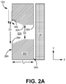
- FIG. 2A illustrates a portion of side 20A of tooling fixture 12A, oriented along the y-axis.
- Tooling fixture 12A includes inner (i.e., preform-facing) surface 24A, oppositely disposed outer surface 26A, and thickness T A extending therebetween. Thickness T A need not be uniform across the entirety of tooling fixture 12A, although FIG. 2A depicts a section of uniform thickness.
- Each hole 22A includes inlet 28A at outer surface 26A and outlet 30A at inner surface 24A. Reactant gas travels through tooling fixture 12A in an inlet-to-outlet direction during CVI.
- Hole 22A can include an inlet portion extending between inlet 28A and transition point 32A, and an outlet portion extending between transition point 32A and outlet 30A.
- Hole 22A has a frustoconical three-dimensional geometry between inlet 28A and transition point 32A (i.e., inlet portion) forming a trapezoidal cross-sectional area (i.e., the plane visible in FIG. 2A ).
- Hole 22A transitions to a cylindrical three-dimensional geometry at transition point 32A, forming a rectangular cross-sectional area between transition point 32A and outlet 30A (i.e., outlet portion). Accordingly, hole 22A has a first diameter D1 at inlet 28A which tapers linearly to transition point 32A, and a uniform second diameter D1 between transition point 32A and outlet 30A.
- D1 is the largest diameter of hole 22A, and D1 > D2.
- D2 can be 0.125 in (3.175 mm), and D1 can be 0.131 in (3.327 mm) to 0.25 in (6.35 mm).
- Corners 34A are formed where inlet 28A meets outer surface 26A.
- the frustoconical geometry at inlet 28A forms a reduced (i.e., ⁇ 90°) open angle ( FIG. 3 ) at the upstream/upper corner 34A with respect to the y-axis and the flow of reactant gas, which reduces pressure loss through hole 22A. More specifically, the pressure drop coefficient K L for the frustoconical geometry can be lower than for a conical hole forming a right angle at outer surface 26A.
- FIG. 2B illustrates a portion wall 20B of tooling fixture 12B which is substantially similar to wall 20A, having inner surface 24B, outer surface 26B and thickness T B extending therebetween.
- Hole 22B can include an inlet portion extending between inlet 28B and transition point 32B, and an outlet portion extending between transition point 32B and outlet 30B.
- Wall 20B differs from wall 20B in that hole 22B has a frustoconical bell mouth three-dimensional geometry (i.e., having an at least partially convexly curved segment) from inlet 28B to transition point 32B, and thereafter has a cylindrical three-dimensional geometry.
- Hole 22B has a first diameter D3 at inlet 28B which curvilinearly tapers to transition point 32B, and a uniform second diameter D4 between transition point 32B and outlet 30B.
- D3 is the largest diameter of hole 22B, and D3 > D4.
- D4 can be 0.125 in (3.175 mm), and D3 can be 0.131 in (3.327 mm) to 0.25 in (6.35 mm).
- Corners 34B are formed where inlet 28B meets outer surface 26B. Corners 34B have non-right angles, with the upstream corner being less than 90°.
- corners 34B are also curved which can help further minimize pressure losses compared to hole 22A, in some cases achieving a lower K L value than hole 22A under similar CVI conditions.
- hole 22B can have more of a parabolic three-dimensional geometry with concave curvature between inlet 28B and transition point 32B.
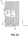
- FIG. 2C illustrates a portion of wall 20C of tooling fixture 12C which is substantially similar to walls 20A and 20B, having inner surface 24C, outer surface 26C and thickness Tc extending therebetween.
- Hole 22C can include an inlet portion extending between inlet 28C and transition point 32C, and an outlet portion extending between transition point 32C and outlet 30C.
- Wall 20C differs from walls 20A and 20B in that hole 22C is directionally angled toward the flow of reactant gas, with a bell mouth shaped upstream corner 34C and a pointed downstream corner 34C.
- the geometry transitions to a cylinder, oriented along the x-axis at transition point 32C.
- Hole 22C has a first diameter D5 at inlet 28C which can be slightly larger, depending on the curvature, than the remaining diameter of the angled segment (i.e., upstream of transition point 32C) which otherwise remains fairly uniform between inlet 28C and transition point 32C.
- Hole 22C further includes second diameter D6 of the conical segment, which is uniform between transition point 32C and outlet 30C.
- D5 > D6, or D5 D6.
- D6 can be 0.125 in (3.175 mm). Corners 34C are formed where inlet 28C meets outer surface 26C. Corners 34C have non-right angles, with the upstream corner being less than 90°. Angling inlet 28C in the flow direction eliminates right angles, and further rounding upstream corner 34C can reduce pressure losses in the same manner as the preceding examples.
- FIG. 3 is a simplified illustration of a portion of wall 120 showing upstream corner 134, based on the direction of flow of reactant gases (represented as dashed arrows) along the y-axis.
- Corner 134 is formed where outer surface 126 of wall 120 meets inlet 128.
- Line 136 represents the inner surface of a cylindrical hole, forming a 90° open angle at corner 134.
- Line 138 represents the inner surface of a hole (i.e., hole 22A) with a frustoconical geometry at the inlet portion, such that the inner surface forms an open angle at corner 134 that is less than 90°.
- line 140 represents the inner surface of a hole (i.e., hole 22B or 22C) with a curved/ bell mouth inner surface also forming open angle at corner 134 that is less than 90°.
- holes 22A, 22B, and/or 22C can be included in a single wall and/or tooling fixture and/or combined with cylindrical holes depending on preform characteristics and/or placement of the tooling fixture within the CVI reactor.
- holes 22A, 22B, and/or 22C can be formed in walls expected to be parallel to the flow of reactant gas. They can also be formed in tooling fixture walls/locations aligned with a local preform thickness that is relatively thick, or in locations situated further from the reactant gas injection site/inlet where the concentration becomes more depleted.
- Holes 22A, 22B, and 22C can be formed using a laser or mechanical drilling technique, including countersinking for frustoconical sections, and trepanning for curved and/or bell mouth inlets.
- the disclosed tooling fixtures can be used to form CMC components for aerospace, maritime, or industrial equipment, to name a few, non-limiting examples.
- a tooling fixture suitable for use in infiltrating a fibrous preform with a flow of reactant gas includes at least one wall.
- the at least one wall includes an outer surface and opposing inner surface defining a thickness therebetween, and a plurality of holes extending through the thickness.
- Each hole of the plurality of holes includes an inlet at the outer surface, an outlet at the inner surface, a transition point between the inlet and the outlet, and a first corner defined by the outer surface and the inlet.
- An angle of the first corner is less than 90 degrees
- each hole of the plurality of holes has a first diameter at the inlet and a second diameter at the outlet, and the second diameter is less than the first diameter.
- the tooling fixture of the preceding paragraph can optionally include, additionally and/or alternatively, any one or more of the following features, configurations and/or additional components:
- the first corner can be rounded.
- each hole of the plurality of holes can further include a frustoconical bell mouth geometry between the inlet and the transition point, and a cylindrical geometry between the transition point and the outlet.
- each hole of the plurality of holes can further include an angled geometry between the inlet and the transition point, and a cylindrical geometry between the transition point and the outlet.
- each hole of the plurality of holes can further include a frustoconical geometry between the inlet and the transition point, and a cylindrical geometry between the transition point and the outlet.
- the at least one wall can be disposed along a flow axis of the reactant gas.
- the tooling fixture can be formed from at least one of graphite, a refractory metal alloy, a carbon-carbon composite, and a ceramic material.
- a tooling fixture suitable for use in infiltrating a fibrous preform with a flow of reactant gas includes at least one wall.
- the at least one wall includes an outer surface and opposing inner surface defining a thickness therebetween, and a plurality of holes extending through the thickness.
- Each hole of the plurality of holes includes an inlet at the outer surface, an outlet at the inner surface, a transition point between the inlet and the outlet, and a first corner defined by the outer surface and the inlet. An angle of the first corner is less than 90 degrees.
- the tooling fixture of the preceding paragraph can optionally include, additionally and/or alternatively, any one or more of the following features, configurations and/or additional components:
- the first corner can be rounded.
- Any of the above tooling fixtures can further include a second corner defined by the outer surface and the inlet.
- the second corner can be rounded.
- each hole of the plurality of holes can further include a frustoconical bell mouth geometry between the inlet and the transition point, and a cylindrical geometry between the transition point and the outlet.
- each hole of the plurality of holes can further include a first diameter at the inlet, and a uniform second diameter from the transition point to the outlet.
- the first diameter can be greater than the second diameter.
- each hole of the plurality of holes can further include an angled geometry between the inlet and the transition point, and a cylindrical geometry between the transition point and the outlet.
- each hole of the plurality of holes can further include a first diameter at the inlet, and a uniform second diameter from the transition point to the outlet.
- the first diameter can be greater than the second diameter.
- each hole of the plurality of holes can further include a frustoconical geometry between the inlet and the transition point, and a cylindrical geometry between the transition point and the outlet.
- each hole of the plurality of holes can further include a first diameter at the inlet, and a uniform second diameter from the transition point to the outlet.
- the first diameter can be greater than the second diameter.
- the at least one wall can be disposed along a flow axis of the reactant gas.
- Any of the above tooling fixtures can further include a second wall disposed orthogonal or parallel to the at least one wall.
- the tooling fixture can be formed from at least one of graphite, a refractory metal alloy, a carbon-carbon composite, and a ceramic material.
Landscapes
- Chemical & Material Sciences (AREA)
- Engineering & Computer Science (AREA)
- Ceramic Engineering (AREA)
- Organic Chemistry (AREA)
- Materials Engineering (AREA)
- Structural Engineering (AREA)
- Chemical Kinetics & Catalysis (AREA)
- General Chemical & Material Sciences (AREA)
- Mechanical Engineering (AREA)
- Metallurgy (AREA)
- Manufacturing & Machinery (AREA)
- Composite Materials (AREA)
- Chemical Vapour Deposition (AREA)
Abstract
Description
- The present invention relates to chemical vapor infiltration (CVI), and more particularly to improved tooling for CVI.
- Ceramic matrix composite (CMC) parts are widely fabricated by applying an interface coating (IFC) to preforms made from woven fabrics or oriented/braided fiber tows. To keep the preforms in a rigid form and maintain proper shape and geometry, perforated tooling can be used to hold the preforms during the initial densification cycle(s). Holes in the tooling allow vaporous precursors to infiltrate into the preform for the deposition of a ceramic matrix. Tooling for simple preform shapes can be designed with uniform hole dimensions. When used with complexly-shaped preforms such as turbine airfoils, vaporous precursors may not sufficiently infiltrate the preform at certain locations through such holes. The result can be differential deposition rate and effective IFC thickness, which can drive differences in mechanical behavior and durability of the CMC part. Thus, a need exists for improved tooling.
- A tooling fixture suitable for use in infiltrating a fibrous preform with a flow of reactant gas includes at least one wall. The at least one wall includes an outer surface and opposing inner surface defining a thickness therebetween, and a plurality of holes extending through the thickness. Each hole of the plurality of holes includes an inlet at the outer surface, an outlet at the inner surface, a transition point between the inlet and the outlet, and a first corner defined by the outer surface and the inlet. An angle of the first corner is less than 90 degrees, each hole of the plurality of holes has a first diameter at the inlet and a second diameter at the outlet, and the second diameter is less than the first diameter.
- A tooling fixture suitable for use in infiltrating a fibrous preform with a flow of reactant gas includes at least one wall. The at least one wall includes an outer surface and opposing inner surface defining a thickness therebetween, and a plurality of holes extending through the thickness. Each hole of the plurality of holes includes an inlet at the outer surface, an outlet at the inner surface, a transition point between the inlet and the outlet, and a first corner defined by the outer surface and the inlet. An angle of the first corner is less than 90 degrees.
- Features of embodiments are set forth in the dependent claims.
-
-
FIG. 1 is a simplified illustration of a tooling fixture within a CVI reactor. -
FIG. 2A is a simplified cross-sectional illustration of a tooling fixture with infiltration holes according to a first embodiment. -
FIG. 2B is a simplified cross-sectional illustration of a tooling fixture with infiltration holes according to a second embodiment. -
FIG. 2C is a simplified cross-sectional illustration of a tooling fixture with infiltration holes according to a third embodiment. -
FIG. 3 is a simplified illustration comparing the angles of the upstream corner of various infiltrations holes ofFIGS. 2A-2C . - While the above-identified figures set forth one or more embodiments of the present disclosure, other embodiments are also contemplated, as noted in the discussion. In all cases, this disclosure presents the invention by way of representation and not limitation. It should be understood that numerous other modifications and embodiments can be devised by those skilled in the art, which fall within the scope and spirit of the principles of the invention. The figures may not be drawn to scale, and applications and embodiments of the present invention may include features and components not specifically shown in the drawings.
- This disclosure presents various inlet geometries for infiltration holes in a tooling fixture. More specifically, the inlets are widened and/or angled with respect to a flow of reactant gas based on the orientation of the tooling fixture within a CVI reactor. Such geometries minimize pressure losses and/or flow vortices to ensure sufficient flow volume through the holes.
-
FIG. 1 is a simplified illustration oftooling fixture 10 positioned withCVI reactor 12. Toolingfixture 10 is supportingpreform 14. Toolingfixture 12 can, in an exemplary embodiment, be formed from graphite. In an alternative embodiment,tooling fixture 12 can be all or partially formed from refractory metal alloys, carbon-carbon composites, and/or a ceramic (e.g., silicon carbide, aluminum oxide, boron nitride, etc.). Preform 14 can be formed from tows of silicon carbide (SiC) or other ceramic fibers arranged in one of various two or three-dimensional woven architectures such as plain, harness (e.g., 3, 5, 8, etc.), twill, braid, or non-symmetric to name a few non-limiting examples. In an alternative embodiment,preform 14 can be formed from nonwoven (e.g., chopped, felted, etc.) fibers. Toolingfixture 12 can at least partially surroundpreform 14 to help maintain the shape ofpreform 14 during CVI. Toolingfixture 12 andpreform 14 can each include straight and/or curved segments depending on the geometry desired in the final CMC part. - CVI
reactor 12 includesinlet 16 andoutlet 18. A flow of reactant gas, represented by dashed arrows, can be introduced toCVI reactor 12 atinlet 16 and exhausted fromCVI reactor 12 atoutlet 18. This flow of reactant gas therefore travels primarily along the y-axis (i.e., flow axis).Tooling fixture 12 includes multiple walls/sides 20 withinfiltration holes 22 extending therethrough. Theuppermost side 20,proximate inlet 16 is disposed along the x-axis such that the flow of reactant gas is mostly normal to its surface, and parallel with itsrespective holes 22. Forsides 20 disposed along the y-axis, however,holes 22 are essentially disposed at a right angle with respect to the flow of reactant gas, as is shown in greater detail inFIGS. 2A-2C . - For uniformly conical (i.e., straight-walled) holes, pressure loss and/or flow vortices at the hole's inlet caused by the turning of the flow into the inlet can at least partially block additional flow into the inlet, leading to insufficient flow of reactant gas through tooling fixture sides oriented in the flow direction. This can result in uneven IFC deposition on corresponding preform surfaces.
-
FIGS. 2A ,2B , and2C are simplified enlarged cross-sectional illustrations ofalternative infiltration holes FIGS. 2A ,2B , and2C are discussed together. -
FIG. 2A illustrates a portion ofside 20A oftooling fixture 12A, oriented along the y-axis.Tooling fixture 12A includes inner (i.e., preform-facing)surface 24A, oppositely disposedouter surface 26A, and thickness TA extending therebetween. Thickness TA need not be uniform across the entirety oftooling fixture 12A, althoughFIG. 2A depicts a section of uniform thickness. Eachhole 22A includesinlet 28A atouter surface 26A andoutlet 30A atinner surface 24A. Reactant gas travels throughtooling fixture 12A in an inlet-to-outlet direction during CVI.Hole 22A can include an inlet portion extending betweeninlet 28A andtransition point 32A, and an outlet portion extending betweentransition point 32A andoutlet 30A.Hole 22A has a frustoconical three-dimensional geometry betweeninlet 28A andtransition point 32A (i.e., inlet portion) forming a trapezoidal cross-sectional area (i.e., the plane visible inFIG. 2A ).Hole 22A transitions to a cylindrical three-dimensional geometry attransition point 32A, forming a rectangular cross-sectional area betweentransition point 32A andoutlet 30A (i.e., outlet portion). Accordingly, hole 22A has a first diameter D1 atinlet 28A which tapers linearly totransition point 32A, and a uniform second diameter D1 betweentransition point 32A andoutlet 30A. D1 is the largest diameter ofhole 22A, and D1 > D2. In an exemplary embodiment, D2 can be 0.125 in (3.175 mm), and D1 can be 0.131 in (3.327 mm) to 0.25 in (6.35 mm).Corners 34A are formed whereinlet 28A meetsouter surface 26A. The frustoconical geometry atinlet 28A forms a reduced (i.e., < 90°) open angle (FIG. 3 ) at the upstream/upper corner 34A with respect to the y-axis and the flow of reactant gas, which reduces pressure loss throughhole 22A. More specifically, the pressure drop coefficient KL for the frustoconical geometry can be lower than for a conical hole forming a right angle atouter surface 26A. -
FIG. 2B illustrates aportion wall 20B oftooling fixture 12B which is substantially similar towall 20A, havinginner surface 24B,outer surface 26B and thickness TB extending therebetween.Hole 22B can include an inlet portion extending betweeninlet 28B andtransition point 32B, and an outlet portion extending betweentransition point 32B andoutlet 30B.Wall 20B differs fromwall 20B in thathole 22B has a frustoconical bell mouth three-dimensional geometry (i.e., having an at least partially convexly curved segment) frominlet 28B totransition point 32B, and thereafter has a cylindrical three-dimensional geometry.Hole 22B has a first diameter D3 atinlet 28B which curvilinearly tapers totransition point 32B, and a uniform second diameter D4 betweentransition point 32B andoutlet 30B. D3 is the largest diameter ofhole 22B, and D3 > D4. In an exemplary embodiment, D4 can be 0.125 in (3.175 mm), and D3 can be 0.131 in (3.327 mm) to 0.25 in (6.35 mm).Corners 34B are formed whereinlet 28B meetsouter surface 26B.Corners 34B have non-right angles, with the upstream corner being less than 90°. In addition to being non-right angles,corners 34B are also curved which can help further minimize pressure losses compared to hole 22A, in some cases achieving a lower KL value thanhole 22A under similar CVI conditions. In an alternative embodiment,hole 22B can have more of a parabolic three-dimensional geometry with concave curvature betweeninlet 28B andtransition point 32B. -
FIG. 2C illustrates a portion of wall 20C oftooling fixture 12C which is substantially similar towalls inner surface 24C,outer surface 26C and thickness Tc extending therebetween. Hole 22C can include an inlet portion extending betweeninlet 28C andtransition point 32C, and an outlet portion extending betweentransition point 32C andoutlet 30C. Wall 20C differs fromwalls upstream corner 34C and a pointeddownstream corner 34C. The geometry transitions to a cylinder, oriented along the x-axis attransition point 32C. Hole 22C has a first diameter D5 atinlet 28C which can be slightly larger, depending on the curvature, than the remaining diameter of the angled segment (i.e., upstream oftransition point 32C) which otherwise remains fairly uniform betweeninlet 28C andtransition point 32C. Hole 22C further includes second diameter D6 of the conical segment, which is uniform betweentransition point 32C andoutlet 30C. Depending on the embodiment, D5 > D6, or D5 = D6. D6 can be 0.125 in (3.175 mm).Corners 34C are formed whereinlet 28C meetsouter surface 26C.Corners 34C have non-right angles, with the upstream corner being less than 90°. Anglinginlet 28C in the flow direction eliminates right angles, and further roundingupstream corner 34C can reduce pressure losses in the same manner as the preceding examples. -
FIG. 3 is a simplified illustration of a portion ofwall 120 showingupstream corner 134, based on the direction of flow of reactant gases (represented as dashed arrows) along the y-axis.Corner 134 is formed whereouter surface 126 ofwall 120 meetsinlet 128.Line 136 represents the inner surface of a cylindrical hole, forming a 90° open angle atcorner 134.Line 138 represents the inner surface of a hole (i.e.,hole 22A) with a frustoconical geometry at the inlet portion, such that the inner surface forms an open angle atcorner 134 that is less than 90°. Similarly,line 140 represents the inner surface of a hole (i.e.,hole 22B or 22C) with a curved/ bell mouth inner surface also forming open angle atcorner 134 that is less than 90°. - Any of
holes Holes - The following are non-exclusive descriptions of possible embodiments of the present invention.
- A tooling fixture suitable for use in infiltrating a fibrous preform with a flow of reactant gas includes at least one wall. The at least one wall includes an outer surface and opposing inner surface defining a thickness therebetween, and a plurality of holes extending through the thickness. Each hole of the plurality of holes includes an inlet at the outer surface, an outlet at the inner surface, a transition point between the inlet and the outlet, and a first corner defined by the outer surface and the inlet. An angle of the first corner is less than 90 degrees, each hole of the plurality of holes has a first diameter at the inlet and a second diameter at the outlet, and the second diameter is less than the first diameter.
- The tooling fixture of the preceding paragraph can optionally include, additionally and/or alternatively, any one or more of the following features, configurations and/or additional components:
In the above tooling fixture, the first corner can be rounded. - In any of the above tooling fixtures, each hole of the plurality of holes can further include a frustoconical bell mouth geometry between the inlet and the transition point, and a cylindrical geometry between the transition point and the outlet.
- In any of the above tooling fixtures, each hole of the plurality of holes can further include an angled geometry between the inlet and the transition point, and a cylindrical geometry between the transition point and the outlet.
- In any of the above tooling fixtures, each hole of the plurality of holes can further include a frustoconical geometry between the inlet and the transition point, and a cylindrical geometry between the transition point and the outlet.
- In any of the above tooling fixtures, the at least one wall can be disposed along a flow axis of the reactant gas.
- In any of the above tooling fixtures, the tooling fixture can be formed from at least one of graphite, a refractory metal alloy, a carbon-carbon composite, and a ceramic material.
- A tooling fixture suitable for use in infiltrating a fibrous preform with a flow of reactant gas includes at least one wall. The at least one wall includes an outer surface and opposing inner surface defining a thickness therebetween, and a plurality of holes extending through the thickness. Each hole of the plurality of holes includes an inlet at the outer surface, an outlet at the inner surface, a transition point between the inlet and the outlet, and a first corner defined by the outer surface and the inlet. An angle of the first corner is less than 90 degrees.
- The tooling fixture of the preceding paragraph can optionally include, additionally and/or alternatively, any one or more of the following features, configurations and/or additional components:
In the above tooling fixture, the first corner can be rounded. - Any of the above tooling fixtures can further include a second corner defined by the outer surface and the inlet.
- In any of the above tooling fixtures, the second corner can be rounded.
- In any of the above tooling fixtures, each hole of the plurality of holes can further include a frustoconical bell mouth geometry between the inlet and the transition point, and a cylindrical geometry between the transition point and the outlet.
- In any of the above tooling fixtures, each hole of the plurality of holes can further include a first diameter at the inlet, and a uniform second diameter from the transition point to the outlet. The first diameter can be greater than the second diameter.
- In any of the above tooling fixtures, each hole of the plurality of holes can further include an angled geometry between the inlet and the transition point, and a cylindrical geometry between the transition point and the outlet.
- In any of the above tooling fixtures, each hole of the plurality of holes can further include a first diameter at the inlet, and a uniform second diameter from the transition point to the outlet. The first diameter can be greater than the second diameter.
- In any of the above tooling fixtures, each hole of the plurality of holes can further include a frustoconical geometry between the inlet and the transition point, and a cylindrical geometry between the transition point and the outlet.
- In any of the above tooling fixtures, each hole of the plurality of holes can further include a first diameter at the inlet, and a uniform second diameter from the transition point to the outlet. The first diameter can be greater than the second diameter.
- In any of the above tooling fixtures, the at least one wall can be disposed along a flow axis of the reactant gas.
- Any of the above tooling fixtures can further include a second wall disposed orthogonal or parallel to the at least one wall.
- In any of the above tooling fixtures, the tooling fixture can be formed from at least one of graphite, a refractory metal alloy, a carbon-carbon composite, and a ceramic material.
- While the invention has been described with reference to an exemplary embodiment(s), it will be understood by those skilled in the art that various changes may be made and equivalents may be substituted for elements thereof without departing from the scope of the invention. In addition, many modifications may be made to adapt a particular situation or material to the teachings of the invention without departing from the essential scope thereof. Therefore, it is intended that the invention not be limited to the particular embodiment(s) disclosed, but that the invention will include all embodiments falling within the scope of the appended claims.
Claims (12)
- A tooling fixture (12; 12A; 12B; 12C) suitable for use in infiltrating a fibrous preform (14) with a flow of reactant gas, the tooling fixture (12; 12A; 12B; 12C) comprising:
at least one wall (20; 20A; 20B; 20C; 120) comprising:an outer surface (26A; 26B; 26C; 126) and opposing inner surface (24A; 24B; 24C) defining a thickness (TA; TB; TC) therebetween; anda plurality of holes (22; 22A; 22B; 22C) extending through the thickness (TA; TB; TC), each hole (22; 22A; 22B; 22C) of the plurality of holes (22; 22A; 22B; 22C) comprising:an inlet (28A; 28B; 28C; 128) at the outer surface (26A; 26B; 26C; 126);an outlet (30A; 30B; 30C) at the inner surface (24A; 24B; 24C);a transition point (32A; 32B; 32C) between the inlet (28A; 28B; 28C; 128) and the outlet (30A; 30B; 30C); anda first corner (34A; 34B; 34C; 134) defined by the outer surface (26A; 26B; 26C; 126) and the inlet (28A; 28B; 28C; 128);wherein an angle of the first corner (34A; 34B; 34C; 134) is less than 90 degrees;wherein each hole (22; 22A; 22B; 22C) of the plurality of holes (22; 22A; 22B; 22C) has a first diameter (D1; D3; D5) at the inlet (28A; 28B; 28C; 128) and a second diameter (D2;D4; D6) at the outlet (30A; 30B; 30C); andwherein the second diameter (D2; D4; D6) is less than the first diameter (D1; D3; D5). - A tooling fixture (12; 12A; 12B; 12C) suitable for use in infiltrating a fibrous preform (14) with a flow of reactant gas, the tooling fixture (12; 12A; 12B; 12C) comprising:
at least one wall (20; 20A; 20B; 20C; 120) comprising:an outer surface (26A; 26B; 26C; 126) and opposing inner surface (24A; 24B; 24C) defining a thickness (TA; TB; TC) therebetween; anda plurality of holes (22; 22A; 22B; 22C) extending through the thickness (TA; TB; TC), each hole (22; 22A; 22B; 22C) of the plurality of holes (22; 22A; 22B; 22C) comprising:an inlet (28A; 28B; 28C; 128) at the outer surface (26A; 26B; 26C; 126);an outlet (30A; 30B; 30C) at the inner surface (24A; 24B; 24C);a transition point (32A; 32B; 32C) between the inlet (28A; 28B; 28C; 128) and the outer surface (26A; 26B; 26C; 126); anda first corner (34A; 34B; 34C; 134) defined by the outer surface (26A; 26B; 26C; 126) and the inlet (28A; 28B; 28C; 128);wherein an angle of the first corner (34A; 34B; 34C; 134) is less than 90 degrees. - The tooling fixture of claim 1 or 2, wherein the first corner (34A; 34B; 34C; 134) is rounded.
- The tooling fixture of claim 3 as dependent on claim 2 and further comprising: a second corner defined by the outer surface (26A; 26B; 26C; 126) and the inlet (28A; 28B; 28C; 128).
- The tooling fixture of claim 4, wherein the second corner is rounded.
- The tooling fixture of any preceding claim, wherein each hole (22; 22B) of the plurality of holes (22; 22B) further comprises:a frustoconical bell mouth geometry between the inlet (28B; 128) and the transition point (32B); anda cylindrical geometry between the transition point (32B) and the outlet (30B).
- The tooling fixture of any of claims 1 to 5, wherein each hole (22; 22A) of the plurality of holes (22; 22A) further comprises:an angled geometry between the inlet (28A; 128) and the transition point (32A); anda cylindrical geometry between the transition point (32A) and the outlet (30A).
- The tooling fixture of any of claims 1 to 5, wherein each hole of the plurality of holes (22; 22A) further comprises:a frustoconical geometry between the inlet (28A; 128) and the transition point (32A); anda cylindrical geometry between the transition point (32A) and the outlet (30A).
- The tooling fixture of any of claims 6 to 8 as dependent on claim 2 directly or indirectly, wherein each hole (22; 22A; 22B; 22C) of the plurality of holes (22; 22A; 22B; 22C) further comprises:a first diameter (D1; D3; D5) at the inlet (28A; 28B; 28C; 128); anda uniform second diameter (D2; D4; D6) from the transition point (32A; 32B; 32C) to the outlet (30A; 30B; 30C);wherein the first diameter (D1; D3; D5) is greater than the second diameter (D2; D4; D6).
- The tooling fixture of any preceding claim, wherein the at least one wall (20; 20A; 20B; 20C; 120) is disposed along a flow axis of the reactant gas.
- The tooling fixture of claim 10 and further comprising: a second wall (20; 20A; 20B; 20C; 120) disposed orthogonal or parallel to the at least one wall (20; 20A; 20B; 20C; 120).
- The tooling fixture of any preceding claim, wherein the tooling fixture (12; 12A; 12B; 12C) is formed from at least one of graphite, a refractory metal alloy, a carbon-carbon composite, and a ceramic material.
Applications Claiming Priority (1)
| Application Number | Priority Date | Filing Date | Title |
|---|---|---|---|
| US18/118,460 US12479775B2 (en) | 2023-03-07 | 2023-03-07 | Chemical vapor infiltration tooling for optimizing infiltration in ceramic matrix composites |
Publications (1)
| Publication Number | Publication Date |
|---|---|
| EP4461845A1 true EP4461845A1 (en) | 2024-11-13 |
Family
ID=90362139
Family Applications (1)
| Application Number | Title | Priority Date | Filing Date |
|---|---|---|---|
| EP24161794.3A Pending EP4461845A1 (en) | 2023-03-07 | 2024-03-06 | Chemical vapor infiltration tooling for optimizing infiltration in ceramic matrix composites |
Country Status (2)
| Country | Link |
|---|---|
| US (1) | US12479775B2 (en) |
| EP (1) | EP4461845A1 (en) |
Citations (9)
| Publication number | Priority date | Publication date | Assignee | Title |
|---|---|---|---|---|
| US4909914A (en) * | 1985-05-11 | 1990-03-20 | Canon Kabushiki Kaisha | Reaction apparatus which introduces one reacting substance within a convergent-divergent nozzle |
| US5217755A (en) * | 1990-12-18 | 1993-06-08 | Societe Europeenne De Propulsion | Chemical vapor infiltration method utilizing substantially diffusive conditions |
| US20120097330A1 (en) * | 2010-10-20 | 2012-04-26 | Applied Materials, Inc. | Dual delivery chamber design |
| US20150214009A1 (en) * | 2014-01-25 | 2015-07-30 | Yuri Glukhoy | Showerhead-cooler system of a semiconductor-processing chamber for semiconductor wafers of large area |
| US20170114462A1 (en) * | 2015-10-26 | 2017-04-27 | Applied Materials, Inc. | High productivity pecvd tool for wafer processing of semiconductor manufacturing |
| US11332827B2 (en) * | 2019-03-27 | 2022-05-17 | Applied Materials, Inc. | Gas distribution plate with high aspect ratio holes and a high hole density |
| US20220195606A1 (en) * | 2020-12-23 | 2022-06-23 | Raytheon Technologies Corporation | Method for metal vapor infiltration of cmc parts and articles containing the same |
| JP7164632B2 (en) * | 2018-06-08 | 2022-11-01 | アプライド マテリアルズ インコーポレイテッド | Temperature controlled gas diffuser for flat panel process equipment |
| US20230047104A1 (en) * | 2019-12-12 | 2023-02-16 | AP&S International GmbH | Apparatus for electroless metallization of a target surface of at least one workpiece, and method and diffuser plate for this purpose |
Family Cites Families (15)
| Publication number | Priority date | Publication date | Assignee | Title |
|---|---|---|---|---|
| US3991248A (en) | 1972-03-28 | 1976-11-09 | Ducommun Incorporated | Fiber reinforced composite product |
| JPS58176196A (en) | 1982-04-06 | 1983-10-15 | Matsushita Electric Ind Co Ltd | Apparatus for growing crystal from compound |
| JP4849705B2 (en) | 2000-03-24 | 2012-01-11 | 東京エレクトロン株式会社 | Plasma processing apparatus, plasma generation introducing member, and dielectric |
| KR100766132B1 (en) * | 2005-08-31 | 2007-10-12 | 코바렌트 마테리얼 가부시키가이샤 | Gas dispersion plate and manufacturing method therefor |
| US20080302303A1 (en) | 2007-06-07 | 2008-12-11 | Applied Materials, Inc. | Methods and apparatus for depositing a uniform silicon film with flow gradient designs |
| JP5093165B2 (en) | 2009-03-17 | 2012-12-05 | 株式会社Ihi | Structure manufacturing method and structure |
| US8845806B2 (en) | 2010-10-22 | 2014-09-30 | Asm Japan K.K. | Shower plate having different aperture dimensions and/or distributions |
| FR3059679B1 (en) | 2016-12-07 | 2021-03-12 | Safran Ceram | CONFORMATION TOOLS AND PLANT FOR CHEMICAL GAS INFILTRATION OF FIBROUS PREFORMS |
| US20180340257A1 (en) | 2017-05-25 | 2018-11-29 | Applied Materials, Inc. | Diffuser for uniformity improvement in display pecvd applications |
| CN107266099B (en) | 2017-06-16 | 2023-07-18 | 中国人民解放军第五七一九工厂 | Clamp for near-net forming of ceramic matrix composite turbine guide vane of aero-engine |
| US11820716B2 (en) | 2018-10-18 | 2023-11-21 | Rolls Royce North American Technologies Inc. | Method of fabricating cooling features on a ceramic matrix composite (CMC) component |
| US11046620B2 (en) | 2018-10-18 | 2021-06-29 | Rolls-Royce Corporation | Method of processing a ceramic matrix composite (CMC) component |
| US10906842B2 (en) | 2018-10-18 | 2021-02-02 | Rolls-Royce High Temperature Composites Inc. | Method of processing a ceramic matrix composite (CMC) component |
| US11472747B2 (en) | 2019-10-08 | 2022-10-18 | Rolls-Royce High Temperature Composites Inc. | Assembly for chemical vapor infiltration of a fiber preform and method of infiltrating a fiber preform |
| CN115181959B (en) | 2022-06-21 | 2023-09-01 | 西安鑫垚陶瓷复合材料有限公司 | Large thin-wall ceramic matrix composite part processing and depositing tool, processing method and using method |
-
2023
- 2023-03-07 US US18/118,460 patent/US12479775B2/en active Active
-
2024
- 2024-03-06 EP EP24161794.3A patent/EP4461845A1/en active Pending
Patent Citations (9)
| Publication number | Priority date | Publication date | Assignee | Title |
|---|---|---|---|---|
| US4909914A (en) * | 1985-05-11 | 1990-03-20 | Canon Kabushiki Kaisha | Reaction apparatus which introduces one reacting substance within a convergent-divergent nozzle |
| US5217755A (en) * | 1990-12-18 | 1993-06-08 | Societe Europeenne De Propulsion | Chemical vapor infiltration method utilizing substantially diffusive conditions |
| US20120097330A1 (en) * | 2010-10-20 | 2012-04-26 | Applied Materials, Inc. | Dual delivery chamber design |
| US20150214009A1 (en) * | 2014-01-25 | 2015-07-30 | Yuri Glukhoy | Showerhead-cooler system of a semiconductor-processing chamber for semiconductor wafers of large area |
| US20170114462A1 (en) * | 2015-10-26 | 2017-04-27 | Applied Materials, Inc. | High productivity pecvd tool for wafer processing of semiconductor manufacturing |
| JP7164632B2 (en) * | 2018-06-08 | 2022-11-01 | アプライド マテリアルズ インコーポレイテッド | Temperature controlled gas diffuser for flat panel process equipment |
| US11332827B2 (en) * | 2019-03-27 | 2022-05-17 | Applied Materials, Inc. | Gas distribution plate with high aspect ratio holes and a high hole density |
| US20230047104A1 (en) * | 2019-12-12 | 2023-02-16 | AP&S International GmbH | Apparatus for electroless metallization of a target surface of at least one workpiece, and method and diffuser plate for this purpose |
| US20220195606A1 (en) * | 2020-12-23 | 2022-06-23 | Raytheon Technologies Corporation | Method for metal vapor infiltration of cmc parts and articles containing the same |
Also Published As
| Publication number | Publication date |
|---|---|
| US12479775B2 (en) | 2025-11-25 |
| US20240300863A1 (en) | 2024-09-12 |
Similar Documents
| Publication | Publication Date | Title |
|---|---|---|
| US7306826B2 (en) | Use of biased fabric to improve properties of SiC/SiC ceramic composites for turbine engine components | |
| EP1676822B1 (en) | SiC/SiC composites incorporating uncoated fibers to improve interlaminar strength | |
| US7329101B2 (en) | Ceramic composite with integrated compliance/wear layer | |
| US10294802B2 (en) | Turbine engine components with chemical vapor infiltrated isolation layers | |
| US9453421B2 (en) | Apparatus having engineered surface feature and method to reduce wear and friction between CMC-to-metal attachment and interface | |
| CN102782256A (en) | Turbine engine blade made of composite material and method of manufacturing same | |
| EP2716871B1 (en) | Turbine blade, and turbine blade fabrication process | |
| EP3061603A1 (en) | Cmc laminate structure fabricated using chemical vapor infiltration (cvi) | |
| EP4427896A1 (en) | Methods for complex geometry mandrel removal of ceramic matrix composite components | |
| EP4461845A1 (en) | Chemical vapor infiltration tooling for optimizing infiltration in ceramic matrix composites | |
| US20210024427A1 (en) | Cmc system for improved infiltration | |
| EP4428264A2 (en) | Chemical vapor infiltration tooling hole modification for optimizing infiltration in ceramic matrix composites | |
| EP3760604B1 (en) | Method of forming cooling channels in a ceramic matrix composite component | |
| CN103890366B (en) | Devices for attaching hollow parts | |
| EP4357114A1 (en) | Floating tooling assembly for chemical vapor infiltration | |
| EP4442856A2 (en) | Chemical vapor infiltration tooling for optimizing infiltration in ceramic matrix composites | |
| US20240110280A1 (en) | Minimization of chemical vapor infiltration tooling hole length through counterbores | |
| EP4345186A1 (en) | Minimization of chemical vapor infiltration tooling holes length through windows | |
| EP4047183B1 (en) | Bifurcating layup for airfoil rib, methods of manufacture thereof and articles comprising the same | |
| US20240109816A1 (en) | Ceramic matrix composite tooling for chemical vapor infiltration process | |
| EP4549416A1 (en) | Variable z-channel hole pattern |
Legal Events
| Date | Code | Title | Description |
|---|---|---|---|
| PUAI | Public reference made under article 153(3) epc to a published international application that has entered the european phase |
Free format text: ORIGINAL CODE: 0009012 |
|
| STAA | Information on the status of an ep patent application or granted ep patent |
Free format text: STATUS: THE APPLICATION HAS BEEN PUBLISHED |
|
| AK | Designated contracting states |
Kind code of ref document: A1 Designated state(s): AL AT BE BG CH CY CZ DE DK EE ES FI FR GB GR HR HU IE IS IT LI LT LU LV MC ME MK MT NL NO PL PT RO RS SE SI SK SM TR |
|
| STAA | Information on the status of an ep patent application or granted ep patent |
Free format text: STATUS: REQUEST FOR EXAMINATION WAS MADE |
|
| 17P | Request for examination filed |
Effective date: 20250507 |
|
| GRAP | Despatch of communication of intention to grant a patent |
Free format text: ORIGINAL CODE: EPIDOSNIGR1 |
|
| STAA | Information on the status of an ep patent application or granted ep patent |
Free format text: STATUS: GRANT OF PATENT IS INTENDED |
|
| INTG | Intention to grant announced |
Effective date: 20260119 |
|
| RIN1 | Information on inventor provided before grant (corrected) |
Inventor name: PREUSS, DANIEL P. Inventor name: LAZUR, ANDREW JOSEPH Inventor name: LENZ, BRENDAN Inventor name: THORNTON, LANE M. Inventor name: COLBY, MARY |
|
| GRAJ | Information related to disapproval of communication of intention to grant by the applicant or resumption of examination proceedings by the epo deleted |
Free format text: ORIGINAL CODE: EPIDOSDIGR1 |
|
| STAA | Information on the status of an ep patent application or granted ep patent |
Free format text: STATUS: REQUEST FOR EXAMINATION WAS MADE |
|
| GRAP | Despatch of communication of intention to grant a patent |
Free format text: ORIGINAL CODE: EPIDOSNIGR1 |
|
| STAA | Information on the status of an ep patent application or granted ep patent |
Free format text: STATUS: GRANT OF PATENT IS INTENDED |