EP4461621A1 - Method of managing a hydraulic circuit of an electric work vehicle - Google Patents
Method of managing a hydraulic circuit of an electric work vehicle Download PDFInfo
- Publication number
- EP4461621A1 EP4461621A1 EP24172854.2A EP24172854A EP4461621A1 EP 4461621 A1 EP4461621 A1 EP 4461621A1 EP 24172854 A EP24172854 A EP 24172854A EP 4461621 A1 EP4461621 A1 EP 4461621A1
- Authority
- EP
- European Patent Office
- Prior art keywords
- hydraulic
- hydraulic pump
- speed
- steering
- power steering
- Prior art date
- Legal status (The legal status is an assumption and is not a legal conclusion. Google has not performed a legal analysis and makes no representation as to the accuracy of the status listed.)
- Granted
Links
Images

Classifications
-
- B—PERFORMING OPERATIONS; TRANSPORTING
- B62—LAND VEHICLES FOR TRAVELLING OTHERWISE THAN ON RAILS
- B62D—MOTOR VEHICLES; TRAILERS
- B62D5/00—Power-assisted or power-driven steering
- B62D5/06—Power-assisted or power-driven steering fluid, i.e. using a pressurised fluid for most or all the force required for steering a vehicle
- B62D5/07—Supply of pressurised fluid for steering also supplying other consumers ; control thereof
-
- B—PERFORMING OPERATIONS; TRANSPORTING
- B62—LAND VEHICLES FOR TRAVELLING OTHERWISE THAN ON RAILS
- B62D—MOTOR VEHICLES; TRAILERS
- B62D5/00—Power-assisted or power-driven steering
- B62D5/06—Power-assisted or power-driven steering fluid, i.e. using a pressurised fluid for most or all the force required for steering a vehicle
- B62D5/062—Details, component parts
- B62D5/064—Pump driven independently from vehicle engine, e.g. electric driven pump
-
- B—PERFORMING OPERATIONS; TRANSPORTING
- B62—LAND VEHICLES FOR TRAVELLING OTHERWISE THAN ON RAILS
- B62D—MOTOR VEHICLES; TRAILERS
- B62D5/00—Power-assisted or power-driven steering
- B62D5/06—Power-assisted or power-driven steering fluid, i.e. using a pressurised fluid for most or all the force required for steering a vehicle
- B62D5/065—Power-assisted or power-driven steering fluid, i.e. using a pressurised fluid for most or all the force required for steering a vehicle characterised by specially adapted means for varying pressurised fluid supply based on need, e.g. on-demand, variable assist
Definitions
- the present invention relates to the field of electric work vehicles, including the so-called Wheel Loaders and in particular in the field of electric work vehicles equipped with a single hydraulic circuit for actuation of at least one hydraulic member and of the vehicular power steering, where the circuit is supplied by a fixed displacement hydraulic pump driven in rotation by an electric motor and in which an oil flow generated by the hydraulic pump is regulated by means of an open center proportional directional valve.
- Compact Wheel Loaders and Wheel Loaders are work machines equipped with a mechanical arm to which a bucket is connected for moving material or earthmoving. Even some agricultural vehicles can be equipped with arms and hydraulic organs.
- the power steering is equipped with a pump that is independent of the other hydraulic organs.
- this solution turns out to be more flexible, it reduces the efficiency from an electrical point of view.
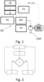
- Figure 1 shows an hydraulic circuit HC of the prior art comprising an exclusively electrically driven hydraulic pump EHP.
- This is arranged to feed a valve or a priority circuit SPV which has the task of feeding a priority control valve of the power steering SV.
- the power steering actuator although present, is not shown.
- Hydraulic services are used to implement a work organ such as an arm and/or bucket.
- These include at least one hydraulic actuator and a related proportional, directional open center control valve.
- the excess oil is sent to the recovery tank T, from where the oil is withdrawn to be pumped back into the circuit.
- the presence of the priority valve or circuit SPV evidently excludes the implementation of a hydraulic pump dedicated to the power steering actuator. In other words, it is evident that the oil flow generated by the hydraulic pump is shared between the power steering and the hydraulic services HS.
- a known solution provides for the electric pump to be kept constantly in operation to guarantee hydraulic flow to the power steering.
- the electric pump supplies only the auxiliary services with the power steering supplied by a separate hydraulic pump
- the control lever such as a joystick J or a roller R
- the corresponding open center directional valve is in the released position (neutral) and simultaneously the electric pump is switched off.
- the open center directional valve shutter is moved to a position other than the release position and the electric pump is activated at a rotational speed proportional to the deflection of the lever.
- the object of the present invention is to propose a method for managing the hydraulic circuit of an electric work vehicle suitable for optimizing the consumption of electric energy, without compromising the performance of the vehicle itself.
- the basic idea of the present invention is to automatically activate the hydraulic pump bringing it to a rotation speed value which represents the greater value between
- the hydraulic pump is maintained at a rotational speed lower than a predetermined threshold called "minimum speed”.
- the first value and the second value are preferably in a look up table.
- the hydraulic pump is activated only if this is actually necessary and the calculation of the flow rate required from the pump is a function of the oil consumer that needs the greater flow rate, while ensuring efficiency at the same time.
- minimum speed it is meant a relatively low speed or equal to zero, which can be a function of other operating parameters of the hydraulic circuit independent of any man/machine interface.
- the "minimum speed” is a function of the hydraulic oil temperature and when the hydraulic oil temperature exceeds a predetermined threshold, then said "minimum speed" is equal to zero.
- the hydraulic pump when the hydraulic oil is at the correct operating temperature, the hydraulic pump is completely deactivated when there is no need to generate a flow of hydraulic oil.
- Fig. 1 shows an electro-hydraulic diagram for controlling the movement of a work member, such as for example an arm A and/or a bucket B shown in Fig. 3 .
- Fig. 3 shows an EV electric work vehicle, for example a loader vehicle, but the present invention also finds application in agricultural vehicles. Therefore, the term “work vehicle” refers to construction, earthmoving and agricultural vehicles. No thermal engine is included.
- the vehicle EV is equipped with an electric energy source, such as a battery pack or a fuel cell for powering an electric propulsion motor (not shown), operatively connected to at least one vehicle wheel W.
- an electric energy source such as a battery pack or a fuel cell for powering an electric propulsion motor (not shown), operatively connected to at least one vehicle wheel W.
- the vehicle has a user location CPT, which houses at least one man/machine interface device, typically a joystick J and/or a wheel R to control the arm and/or the bucket.
- a man/machine interface device typically a joystick J and/or a wheel R to control the arm and/or the bucket.
- the arm A has an elongated shape with a first end hinged to the vehicle chassis F, and a second end, opposite to the first, arranged to support a bucket B.
- the mechanical connections between the arm and the vehicle chassis and between bucket and arm are rotatable to form hinges in a manner per se known.
- the arm A, the bucket B and, in general, any work member is operated by means of a hydraulic actuator HA.
- Fig. 1 therefore shows an electro-hydraulic circuit HC in which a single electric hydraulic pump EHP, arranged to be powered by the aforementioned electric energy source, supplies the hydraulic circuit HC and in particular the hydraulic actuator HA forming part of the so-called hydraulic services HS, which also include an open center proportional directional valve (not shown) for control of the hydraulic actuator HA.
- EHP electric hydraulic pump
- HA hydraulic actuator HA
- hydraulic services HS which also include an open center proportional directional valve (not shown) for control of the hydraulic actuator HA.
- the oil pumped by the hydraulic pump is directed to a collection tank T.
- the hydraulic pump is arranged to recirculate the oil flowing into the collection tank in the hydraulic circuit.
- the hydraulic oil is pumped to the priority valve or circuit SPV arranged to feed the power steering control valve SV as a priority and the excess oil is sent to the hydraulic services HS.
- the hydraulic pump is deactivated when the man/machine interface means are released. In other words, if the operator does not act on the joystick J or on the wheel R or on the steering wheel, the hydraulic pump is deactivated or in any case kept at a minimum speed.
- An action by the operator on the joystick and/or wheel R and/or steering wheel can be associated with a consequent generation of a command signal.
- an angular sensor AS is associated with the relative steering column to measure an angular position of the same.
- the steering wheel angular position signal is acquired and derived over time to calculate the steering wheel actuation rate by the operator.
- the rotational speed of the hydraulic pump EHP is calculated as a function of the rotational speed of the steering wheel: Steering wheel speed (Rouds/s) Hydraulic pump speed (RPM) 0,2 600 0,4 800 0,6 1000 0,8 1200 1,0 1400
- a deviation value of a lever J or of a roller R is constantly acquired, with respect to a relative rest position, for controlling a hydraulic actuator and a second rotation speed value of the hydraulic pump EHP is calculated.
- the second rotation speed value of the hydraulic pump is proportional to the deviation of the lever and/or roller with respect to the relative rest position.
- the greater value between the first speed value and the second speed value of the hydraulic pump is selected and, accordingly, the hydraulic pump speed is regulated.
- the position of the open center directional valve shutter controlling the hydraulic actuator HA of hydraulic services HS is proportional to this deviation.
- the second speed value can be zero, when for example only the steering wheel is operated while the joystick and/or roller are released.
- a single hydraulic pump EHP electric or in any case driven exclusively by an electric motor is configured to feed a hydraulic power steering SV and at least one hydraulic actuator HA of a work member A, B of the electric work vehicle, such as for example an arm and/or or a bucket.
- the hydraulic pump is configured to activate in response to
- the method includes
- the method evidently comprises
- the minimum speed value can be greater than or equal to zero, preferably, depending on the temperature of the hydraulic oil.
- it is greater than zero when the hydraulic oil temperature is lower than a predetermined threshold and equal to zero when the hydraulic oil temperature is greater than or equal to the predetermined threshold.
- the minimum speed can be expressed through the following table as follows: Hydraulic oil temperature (°C) Minimum speed(RPM) -25 700 -20 800 -15 900 -10 1000 -5 1100 0 1300 10 STOP
- the present method is advantageously implemented by means of a processing unit CU configured to receive as input the signals generated by the sensor AS and/or by the joystick J and/or by the wheel R and to control the hydraulic pump EHP accordingly.
- the present invention can advantageously be implemented through a computer program comprising coding means for carrying out one or more steps of the method, when this program is executed on a computer. Therefore it is understood that the scope of protection extends to said computer program and also to computer-readable means comprising a recorded message, said computer-readable means comprising program coding means for carrying out one or more steps of the method, when said program is run on a computer. Variants of the non-limiting example described are possible, without however departing from the scope of protection of the present invention, including all equivalent embodiments for a person skilled in the art, to the contents of the claims.
Landscapes
- Engineering & Computer Science (AREA)
- Chemical & Material Sciences (AREA)
- Combustion & Propulsion (AREA)
- Transportation (AREA)
- Mechanical Engineering (AREA)
- Steering Control In Accordance With Driving Conditions (AREA)
- Operation Control Of Excavators (AREA)
- Fluid-Pressure Circuits (AREA)
Abstract
Description
- The present invention relates to the field of electric work vehicles, including the so-called Wheel Loaders and in particular in the field of electric work vehicles equipped with a single hydraulic circuit for actuation of at least one hydraulic member and of the vehicular power steering, where the circuit is supplied by a fixed displacement hydraulic pump driven in rotation by an electric motor and in which an oil flow generated by the hydraulic pump is regulated by means of an open center proportional directional valve.
- Compact Wheel Loaders and Wheel Loaders are work machines equipped with a mechanical arm to which a bucket is connected for moving material or earthmoving. Even some agricultural vehicles can be equipped with arms and hydraulic organs.
- What this category of vehicles, generically referred to as work vehicles, has in common is that they are entirely electric propelled. Therefore, they are not equipped with an internal combustion engine, but with an electric propulsion motor which acts on at least one wheel without any hydrostat.
- However, electric work vehicles maintain the hydraulic actuation circuit of the boom and/or other work members. This means that a hydraulic pump driven by an electric motor is provided. As long as no hydraulic components are activated, the hydraulic pump remains deactivated to save electric energy. This can happen, for example, while the vehicle is traveling from one workplace to another one. According to some schemes, the power steering is also fed by the same pump that feeds the working organ(s)
- According to other schemes, the power steering is equipped with a pump that is independent of the other hydraulic organs. However, even if this solution turns out to be more flexible, it reduces the efficiency from an electrical point of view.
-
Figure 1 shows an hydraulic circuit HC of the prior art comprising an exclusively electrically driven hydraulic pump EHP. - This is arranged to feed a valve or a priority circuit SPV which has the task of feeding a priority control valve of the power steering SV. The power steering actuator, although present, is not shown.
- The excess oil flow, generated by the hydraulic pump, is sent to the hydraulic services indicated with the block HS. Hydraulic services are used to implement a work organ such as an arm and/or bucket.
- These include at least one hydraulic actuator and a related proportional, directional open center control valve.
- The excess oil is sent to the recovery tank T, from where the oil is withdrawn to be pumped back into the circuit.
- The presence of the priority valve or circuit SPV evidently excludes the implementation of a hydraulic pump dedicated to the power steering actuator. In other words, it is evident that the oil flow generated by the hydraulic pump is shared between the power steering and the hydraulic services HS.
- A known solution provides for the electric pump to be kept constantly in operation to guarantee hydraulic flow to the power steering.
- It is believed that this solution is not optimal.
- According to a scheme in which the electric pump supplies only the auxiliary services with the power steering supplied by a separate hydraulic pump, it is possible to save electricity in the following way:
when the control lever, such as a joystick J or a roller R, of a hydraulic actuator of the hydraulic services is released, the corresponding open center directional valve is in the released position (neutral) and simultaneously the electric pump is switched off. Conversely, when the control lever is deflected from the release position, the open center directional valve shutter is moved to a position other than the release position and the electric pump is activated at a rotational speed proportional to the deflection of the lever. - However, this solution is inefficient when there is only one hydraulic pump supplying the power steering together with the hydraulic services, as in the present invention.
- Unless specifically excluded in the detailed description that follows, what is described in this chapter is to be considered as an integral part of the detailed description.
- The object of the present invention is to propose a method for managing the hydraulic circuit of an electric work vehicle suitable for optimizing the consumption of electric energy, without compromising the performance of the vehicle itself.
- The basic idea of the present invention is to automatically activate the hydraulic pump bringing it to a rotation speed value which represents the greater value between
- A first value proportional to the rotation speed of the steering wheel,
- A second value proportional to a deflection angle of the control lever of a hydraulic actuator.
- Preferably, when the steering wheel is stationary and the actuator control lever is also released, then the hydraulic pump is maintained at a rotational speed lower than a predetermined threshold called "minimum speed".
- The first value and the second value are preferably in a look up table.
- Advantageously, the hydraulic pump is activated only if this is actually necessary and the calculation of the flow rate required from the pump is a function of the oil consumer that needs the greater flow rate, while ensuring efficiency at the same time.
- By "minimum speed" it is meant a relatively low speed or equal to zero, which can be a function of other operating parameters of the hydraulic circuit independent of any man/machine interface.
- Preferably, the "minimum speed" is a function of the hydraulic oil temperature and when the hydraulic oil temperature exceeds a predetermined threshold, then said "minimum speed" is equal to zero.
- Conveniently, when the hydraulic oil is at the correct operating temperature, the hydraulic pump is completely deactivated when there is no need to generate a flow of hydraulic oil.
- The dependent claims describe preferred variants of the invention, forming an integral part of the present description.
- Further objects and advantages of the present invention will become clear from the detailed description that follows of an embodiment of the same (and of its variants) and from the annexed drawings given for purely explanatory and non-limiting purposes, in which:
-
Fig. 1 shows an electro-hydraulic actuation diagram of at least one hydraulic member such as an arm and/or a bucket and a vehicular power steering; -
Fig. 2 shows an exemplary flow diagram of the method object of the present invention; -
Fig. 3 shows an example of a work vehicle in which the present invention is implemented. - The same reference numbers and letters in the figures identify the same elements or components or functions.
- It should also be noted that the terms "first", "second", "third", "superior", "inferior" and the like may be used herein to distinguish various items. These terms do not imply a spatial, sequential, or hierarchical order for the modified items unless specifically indicated or inferred from the text.
- The elements and characteristics illustrated in the various preferred embodiments, including the drawings, can be combined with each other without however departing from the scope of protection of the present application as described below.
-
Fig. 1 shows an electro-hydraulic diagram for controlling the movement of a work member, such as for example an arm A and/or a bucket B shown inFig. 3 . -
Fig. 3 shows an EV electric work vehicle, for example a loader vehicle, but the present invention also finds application in agricultural vehicles. Therefore, the term "work vehicle" refers to construction, earthmoving and agricultural vehicles. No thermal engine is included. - Evidently, the vehicle EV is equipped with an electric energy source, such as a battery pack or a fuel cell for powering an electric propulsion motor (not shown), operatively connected to at least one vehicle wheel W.
- The vehicle has a user location CPT, which houses at least one man/machine interface device, typically a joystick J and/or a wheel R to control the arm and/or the bucket.
- In the example of
figure 3 , the arm A has an elongated shape with a first end hinged to the vehicle chassis F, and a second end, opposite to the first, arranged to support a bucket B. The mechanical connections between the arm and the vehicle chassis and between bucket and arm are rotatable to form hinges in a manner per se known. - The arm A, the bucket B and, in general, any work member is operated by means of a hydraulic actuator HA.
-
Fig. 1 therefore shows an electro-hydraulic circuit HC in which a single electric hydraulic pump EHP, arranged to be powered by the aforementioned electric energy source, supplies the hydraulic circuit HC and in particular the hydraulic actuator HA forming part of the so-called hydraulic services HS, which also include an open center proportional directional valve (not shown) for control of the hydraulic actuator HA. - When the solenoid valve is in the rest position, the oil pumped by the hydraulic pump is directed to a collection tank T. The hydraulic pump is arranged to recirculate the oil flowing into the collection tank in the hydraulic circuit.
- According to the diagram in
Figure 1 , the hydraulic oil is pumped to the priority valve or circuit SPV arranged to feed the power steering control valve SV as a priority and the excess oil is sent to the hydraulic services HS. - According to the present invention, the hydraulic pump is deactivated when the man/machine interface means are released. In other words, if the operator does not act on the joystick J or on the wheel R or on the steering wheel, the hydraulic pump is deactivated or in any case kept at a minimum speed.
- An action by the operator on the joystick and/or wheel R and/or steering wheel can be associated with a consequent generation of a command signal.
- More particularly, regarding the steering wheel, an angular sensor AS is associated with the relative steering column to measure an angular position of the same.
- According to the present invention, the steering wheel angular position signal is acquired and derived over time to calculate the steering wheel actuation rate by the operator. According to the table below, an example is shown of calculating the rotational speed of the hydraulic pump EHP as a function of the rotational speed of the steering wheel:
Steering wheel speed (Rouds/s) Hydraulic pump speed (RPM) 0,2 600 0,4 800 0,6 1000 0,8 1200 1,0 1400 - In the same way, a deviation value of a lever J or of a roller R is constantly acquired, with respect to a relative rest position, for controlling a hydraulic actuator and a second rotation speed value of the hydraulic pump EHP is calculated. In particular, the second rotation speed value of the hydraulic pump is proportional to the deviation of the lever and/or roller with respect to the relative rest position.
- Subsequently, the greater value between the first speed value and the second speed value of the hydraulic pump is selected and, accordingly, the hydraulic pump speed is regulated.
- The position of the open center directional valve shutter controlling the hydraulic actuator HA of hydraulic services HS is proportional to this deviation.
- Obviously, reference is made only to a first speed value and to a second speed value, however the consumers of hydraulic oil can be multiple and the selection of the highest value can be carried out among three or more speed values relating to as many consumers.
- It is further worth pointing out that the second speed value can be zero, when for example only the steering wheel is operated while the joystick and/or roller are released.
- The method of the present invention can be summarized as follows:
a single hydraulic pump EHP electric or in any case driven exclusively by an electric motor is configured to feed a hydraulic power steering SV and at least one hydraulic actuator HA of a work member A, B of the electric work vehicle, such as for example an arm and/or or a bucket. - The hydraulic pump is configured to activate in response to
- a first signal, generated by a position sensor AS associated with the steering wheel, for controlling the power steering, and
- at least a second signal, generated by interface means J, R, different from said steering wheel, to control at least one hydraulic actuator, different from the power steering.
- The method includes
- + (Step 2) a calculation procedure of
- - a first speed value of the hydraulic pump as a function of the steering actuation speed and
- - at least a second rotation speed value of the hydraulic pump as a function of a deviation of the second interface means J, R, with respect to a relative release position,
- + (Step 4) controlling the hydraulic pump according to the higher value between the first and at least one second speed value.
- With reference to
Fig. 2 , the method evidently comprises - + (Step 1) acquisition of the first and second signal;
- + (Step 2) calculation of the first and second speed value as described above;
- + (Step 3) checking that at least one of said first and second values is greater than zero, if so:
- + (Step 4) regulating the hydraulic pump speed as described above, or if not
- + (Step 5) regulating the hydraulic pump speed according to a minimum speed value.
- However, as described above, the minimum speed value can be greater than or equal to zero, preferably, depending on the temperature of the hydraulic oil.
- In particular, it is greater than zero when the hydraulic oil temperature is lower than a predetermined threshold and equal to zero when the hydraulic oil temperature is greater than or equal to the predetermined threshold.
- For example, the minimum speed can be expressed through the following table as follows:
Hydraulic oil temperature (°C) Minimum speed(RPM) -25 700 -20 800 -15 900 -10 1000 -5 1100 0 1300 10 STOP - Conveniently, circulating the hydraulic oil through the priority valve and then through the hydraulic services open center directional valve is exploited to warm the hydraulic oil in cold ambient conditions.
- The present method is advantageously implemented by means of a processing unit CU configured to receive as input the signals generated by the sensor AS and/or by the joystick J and/or by the wheel R and to control the hydraulic pump EHP accordingly.
- Evidently there may also be a temperature sensor not shown which is also operationally connected to the processing unit CU.
- The present invention can advantageously be implemented through a computer program comprising coding means for carrying out one or more steps of the method, when this program is executed on a computer. Therefore it is understood that the scope of protection extends to said computer program and also to computer-readable means comprising a recorded message, said computer-readable means comprising program coding means for carrying out one or more steps of the method, when said program is run on a computer. Variants of the non-limiting example described are possible, without however departing from the scope of protection of the present invention, including all equivalent embodiments for a person skilled in the art, to the contents of the claims.
- From the description given above, the person skilled in the art is capable of realizing the object of the invention without introducing further constructive details.
Claims (9)
- Method of managing a hydraulic circuit of an electric work vehicle (EV), the hydraulic circuit (HC) comprising a single electric hydraulic pump (EHP) configured to supply- a hydraulic power steering (SV) and- at least one hydraulic actuator (HA) of a working element (A, B) of the electric work vehicle,the hydraulic pump being configured to activate in response to. a first signal, generated by a position sensor (AS) associated with a steering wheel, to control said power steering, and/or. at least a second signal, generated by interface means (J, R), different from said steering, to control said at least one hydraulic actuator, different from the power steering,the method including+ a calculation procedure of- a first speed value of the hydraulic pump as a function of an actuation speed of said steering wheel e- at least one second rotation speed value of the hydraulic pump as a function of a deviation of said second interface means (J, R,) with respect to a relative release position,+ controlling of the hydraulic pump according to the higher value between said first and at least second speed value.
- The method according to claim 1, wherein said hydraulic pump is configured to maintain a rotational speed lower than or equal to a predetermined threshold said minimum speed in the absence of said first and second signals.
- Method according to claim 1 or 2, wherein said first speed value of the hydraulic pump is expressed by means of a look up table as a function of the actuation speed of said steering wheel.
- Method according to any one of claims 2 - 3, wherein said minimum speed is greater than zero when a temperature of a hydraulic oil in the hydraulic circuit is lower than a predetermined threshold and equal to zero when said temperature is greater than or equal to said predetermined threshold.
- Method according to claim 3 comprising the following steps in cyclical succession:- (Step 1) Acquisition of said first signal and of said second signal;- (Step 2) Calculation of said first and second speed values;- (Step 3) checking that at least one of said first and second values is greater than zero, if so- (Step 4) regulating the pump speed according to claim 1, or if not- (Step 5) regulating the pump speed according to a minimum speed value.
- A processing unit (CU) for controlling a hydraulic circuit (HC) of an electric work vehicle, the hydraulic circuit comprising an electric hydraulic pump (EHP) configured to power- a hydraulic power steering (SV) and- at least one hydraulic actuator (HA) of a working element (A, B) of the electric work vehicle,the hydraulic pump being configured to activate in response to. a first signal, generated by a position sensor (AS) associated with a steering wheel, for controlling said power steering, and. at least a second signal, generated by interface means (J, R,), different from said steering, to control said at least one hydraulic actuator, different from the power steering,wherein the processing unit is configured for+ calculating- a first speed value of the hydraulic pump as a function of an actuation speed of said steering e- at least one second rotation speed value of the hydraulic pump as a function of a deviation of said second interface means (J, R,) with respect to a relative release position and for+ regulating the hydraulic pump speed according to the higher value between said first and at least second speed values.
- A computer program comprising instructions for causing the processing unit of claim 6 to implement the method according to any one of claims 1 - 5.
- A computer readable medium having stored the program of claim 7.
- Electric work vehicle (EV) comprising- at least one work member, such as an arm (A) and/or a bucket (B),- a hydraulic power steering (SV) ed- at least one hydraulic actuator (HA) for moving said at least one work member (A, B),- a hydraulic circuit (HC) comprising an electric hydraulic pump (EHP) configured to power said hydraulic actuator and said power steering, wherein the hydraulic pump is configured to activate in response to. a first signal, generated by a position sensor (AS) associated with a steering wheel, for controlling said power steering, ed. at least a second signal, generated by interface means (J, R,), different from said steering, to control said at least one hydraulic actuator, different from the power steering,- the processing unit being configured according to claim 6.
Applications Claiming Priority (1)
| Application Number | Priority Date | Filing Date | Title |
|---|---|---|---|
| IT102023000009054A IT202300009054A1 (en) | 2023-05-08 | 2023-05-08 | Method of managing a hydraulic circuit of an electric work vehicle |
Publications (2)
| Publication Number | Publication Date |
|---|---|
| EP4461621A1 true EP4461621A1 (en) | 2024-11-13 |
| EP4461621B1 EP4461621B1 (en) | 2026-04-15 |
Family
ID=87036764
Family Applications (1)
| Application Number | Title | Priority Date | Filing Date |
|---|---|---|---|
| EP24172854.2A Active EP4461621B1 (en) | 2023-05-08 | 2024-04-26 | Method for managing a hydraulic circuit of an electric work vehicle |
Country Status (2)
| Country | Link |
|---|---|
| EP (1) | EP4461621B1 (en) |
| IT (1) | IT202300009054A1 (en) |
Citations (3)
| Publication number | Priority date | Publication date | Assignee | Title |
|---|---|---|---|---|
| US20040149498A1 (en) * | 2002-12-18 | 2004-08-05 | Seiji Nakashima | Steering apparatus for electric industrial vehicle |
| US20060260301A1 (en) * | 2005-05-17 | 2006-11-23 | Nissan Motor Co., Ltd. | Hydraulic pressure supply control in industrial vehicle |
| JP2006321270A (en) * | 2005-05-17 | 2006-11-30 | Nissan Motor Co Ltd | Power steering device and hydraulic control device for industrial vehicle |
-
2023
- 2023-05-08 IT IT102023000009054A patent/IT202300009054A1/en unknown
-
2024
- 2024-04-26 EP EP24172854.2A patent/EP4461621B1/en active Active
Patent Citations (3)
| Publication number | Priority date | Publication date | Assignee | Title |
|---|---|---|---|---|
| US20040149498A1 (en) * | 2002-12-18 | 2004-08-05 | Seiji Nakashima | Steering apparatus for electric industrial vehicle |
| US20060260301A1 (en) * | 2005-05-17 | 2006-11-23 | Nissan Motor Co., Ltd. | Hydraulic pressure supply control in industrial vehicle |
| JP2006321270A (en) * | 2005-05-17 | 2006-11-30 | Nissan Motor Co Ltd | Power steering device and hydraulic control device for industrial vehicle |
Also Published As
| Publication number | Publication date |
|---|---|
| IT202300009054A1 (en) | 2024-11-08 |
| EP4461621B1 (en) | 2026-04-15 |
Similar Documents
| Publication | Publication Date | Title |
|---|---|---|
| JP4862078B2 (en) | Construction machine and method for controlling construction machine | |
| JP5542016B2 (en) | Drive control method for work machine | |
| US9637890B2 (en) | Power transmission device and hybrid construction machine provided therewith | |
| US8612102B2 (en) | Hydraulic excavator and hydraulic excavator control method | |
| JP5511425B2 (en) | Control device for hybrid construction machine | |
| JP6434128B2 (en) | Hybrid work vehicle | |
| EP2685010A1 (en) | Shovel and method for controlling shovel | |
| US9951797B2 (en) | Work machine | |
| JP2005083242A (en) | Drive control device for hybrid work machine | |
| CN107208674A (en) | The hydraulic oil energy regenerating regenerating unit of Work machine | |
| US9211808B2 (en) | Power management for a drive system | |
| US20150275478A1 (en) | Shovel | |
| US11377822B2 (en) | Hydraulic drive apparatus | |
| CN111247027A (en) | Electric construction machine | |
| JP4248378B2 (en) | Drive control device for hybrid work machine | |
| JP2000045955A (en) | Hydraulic device | |
| US10017917B2 (en) | Drive device of construction machine | |
| EP4461621B1 (en) | Method for managing a hydraulic circuit of an electric work vehicle | |
| JP2005081973A (en) | Drive control device for hybrid work machine | |
| JP5596583B2 (en) | Drive control device for work machine | |
| US20250283303A1 (en) | Working machine and method of controlling working machine | |
| JP2008151211A (en) | Engine start system for construction machinery | |
| JP2010048153A (en) | Engine control device | |
| JP2005086892A (en) | Drive control device for hybrid work machine | |
| US10377223B2 (en) | Working machine arranged with means to drive and control a hydraulic pump |
Legal Events
| Date | Code | Title | Description |
|---|---|---|---|
| PUAI | Public reference made under article 153(3) epc to a published international application that has entered the european phase |
Free format text: ORIGINAL CODE: 0009012 |
|
| STAA | Information on the status of an ep patent application or granted ep patent |
Free format text: STATUS: THE APPLICATION HAS BEEN PUBLISHED |
|
| AK | Designated contracting states |
Kind code of ref document: A1 Designated state(s): AL AT BE BG CH CY CZ DE DK EE ES FI FR GB GR HR HU IE IS IT LI LT LU LV MC ME MK MT NL NO PL PT RO RS SE SI SK SM TR |
|
| STAA | Information on the status of an ep patent application or granted ep patent |
Free format text: STATUS: REQUEST FOR EXAMINATION WAS MADE |
|
| 17P | Request for examination filed |
Effective date: 20250513 |
|
| GRAP | Despatch of communication of intention to grant a patent |
Free format text: ORIGINAL CODE: EPIDOSNIGR1 |
|
| STAA | Information on the status of an ep patent application or granted ep patent |
Free format text: STATUS: GRANT OF PATENT IS INTENDED |
|
| RIC1 | Information provided on ipc code assigned before grant |
Ipc: B62D 5/07 20060101AFI20251026BHEP Ipc: B62D 5/06 20060101ALN20251026BHEP Ipc: B62D 5/065 20060101ALN20251026BHEP |
|
| INTG | Intention to grant announced |
Effective date: 20251114 |
|
| RIC1 | Information provided on ipc code assigned before grant |
Ipc: B62D 5/07 20060101AFI20251107BHEP Ipc: B62D 5/06 20060101ALN20251107BHEP Ipc: B62D 5/065 20060101ALN20251107BHEP |
|
| GRAS | Grant fee paid |
Free format text: ORIGINAL CODE: EPIDOSNIGR3 |
|
| GRAA | (expected) grant |
Free format text: ORIGINAL CODE: 0009210 |
|
| STAA | Information on the status of an ep patent application or granted ep patent |
Free format text: STATUS: THE PATENT HAS BEEN GRANTED |
|
| AK | Designated contracting states |
Kind code of ref document: B1 Designated state(s): AL AT BE BG CH CY CZ DE DK EE ES FI FR GB GR HR HU IE IS IT LI LT LU LV MC ME MK MT NL NO PL PT RO RS SE SI SK SM TR |
|
| REG | Reference to a national code |
Ref country code: CH Ref legal event code: F10 Free format text: ST27 STATUS EVENT CODE: U-0-0-F10-F00 (AS PROVIDED BY THE NATIONAL OFFICE) Effective date: 20260415 |
|
| REG | Reference to a national code |
Ref country code: DE Ref legal event code: R096 Ref document number: 602024003907 Country of ref document: DE |
|
| REG | Reference to a national code |
Ref country code: IE Ref legal event code: FG4D |
|
| PGFP | Annual fee paid to national office [announced via postgrant information from national office to epo] |
Ref country code: IT Payment date: 20260430 Year of fee payment: 3 |
|
| PGFP | Annual fee paid to national office [announced via postgrant information from national office to epo] |
Ref country code: DE Payment date: 20260421 Year of fee payment: 3 |
|
| PGFP | Annual fee paid to national office [announced via postgrant information from national office to epo] |
Ref country code: AT Payment date: 20260714 Year of fee payment: 3 |
|
| PGFP | Annual fee paid to national office [announced via postgrant information from national office to epo] |
Ref country code: FR Payment date: 20260423 Year of fee payment: 3 |