EP4461612A1 - Front-drive vehicle torque control method and apparatus, and vehicle - Google Patents
Front-drive vehicle torque control method and apparatus, and vehicle Download PDFInfo
- Publication number
- EP4461612A1 EP4461612A1 EP23737136.4A EP23737136A EP4461612A1 EP 4461612 A1 EP4461612 A1 EP 4461612A1 EP 23737136 A EP23737136 A EP 23737136A EP 4461612 A1 EP4461612 A1 EP 4461612A1
- Authority
- EP
- European Patent Office
- Prior art keywords
- speed
- vehicle
- torque
- rotation speed
- wheel
- Prior art date
- Legal status (The legal status is an assumption and is not a legal conclusion. Google has not performed a legal analysis and makes no representation as to the accuracy of the status listed.)
- Granted
Links
Images

Classifications
-
- B—PERFORMING OPERATIONS; TRANSPORTING
- B60—VEHICLES IN GENERAL
- B60W—CONJOINT CONTROL OF VEHICLE SUB-UNITS OF DIFFERENT TYPE OR DIFFERENT FUNCTION; CONTROL SYSTEMS SPECIALLY ADAPTED FOR HYBRID VEHICLES; ROAD VEHICLE DRIVE CONTROL SYSTEMS FOR PURPOSES NOT RELATED TO THE CONTROL OF A PARTICULAR SUB-UNIT
- B60W30/00—Purposes of road vehicle drive control systems not related to the control of a particular sub-unit, e.g. of systems using conjoint control of vehicle sub-units
- B60W30/18—Propelling the vehicle
- B60W30/18172—Preventing, or responsive to skidding of wheels
-
- B—PERFORMING OPERATIONS; TRANSPORTING
- B60—VEHICLES IN GENERAL
- B60W—CONJOINT CONTROL OF VEHICLE SUB-UNITS OF DIFFERENT TYPE OR DIFFERENT FUNCTION; CONTROL SYSTEMS SPECIALLY ADAPTED FOR HYBRID VEHICLES; ROAD VEHICLE DRIVE CONTROL SYSTEMS FOR PURPOSES NOT RELATED TO THE CONTROL OF A PARTICULAR SUB-UNIT
- B60W10/00—Conjoint control of vehicle sub-units of different type or different function
- B60W10/04—Conjoint control of vehicle sub-units of different type or different function including control of propulsion units
-
- B—PERFORMING OPERATIONS; TRANSPORTING
- B60—VEHICLES IN GENERAL
- B60W—CONJOINT CONTROL OF VEHICLE SUB-UNITS OF DIFFERENT TYPE OR DIFFERENT FUNCTION; CONTROL SYSTEMS SPECIALLY ADAPTED FOR HYBRID VEHICLES; ROAD VEHICLE DRIVE CONTROL SYSTEMS FOR PURPOSES NOT RELATED TO THE CONTROL OF A PARTICULAR SUB-UNIT
- B60W10/00—Conjoint control of vehicle sub-units of different type or different function
- B60W10/04—Conjoint control of vehicle sub-units of different type or different function including control of propulsion units
- B60W10/06—Conjoint control of vehicle sub-units of different type or different function including control of propulsion units including control of combustion engines
-
- B—PERFORMING OPERATIONS; TRANSPORTING
- B60—VEHICLES IN GENERAL
- B60W—CONJOINT CONTROL OF VEHICLE SUB-UNITS OF DIFFERENT TYPE OR DIFFERENT FUNCTION; CONTROL SYSTEMS SPECIALLY ADAPTED FOR HYBRID VEHICLES; ROAD VEHICLE DRIVE CONTROL SYSTEMS FOR PURPOSES NOT RELATED TO THE CONTROL OF A PARTICULAR SUB-UNIT
- B60W10/00—Conjoint control of vehicle sub-units of different type or different function
- B60W10/04—Conjoint control of vehicle sub-units of different type or different function including control of propulsion units
- B60W10/08—Conjoint control of vehicle sub-units of different type or different function including control of propulsion units including control of electric propulsion units, e.g. motors or generators
-
- B—PERFORMING OPERATIONS; TRANSPORTING
- B60—VEHICLES IN GENERAL
- B60W—CONJOINT CONTROL OF VEHICLE SUB-UNITS OF DIFFERENT TYPE OR DIFFERENT FUNCTION; CONTROL SYSTEMS SPECIALLY ADAPTED FOR HYBRID VEHICLES; ROAD VEHICLE DRIVE CONTROL SYSTEMS FOR PURPOSES NOT RELATED TO THE CONTROL OF A PARTICULAR SUB-UNIT
- B60W50/00—Details of control systems for road vehicle drive control not related to the control of a particular sub-unit, e.g. process diagnostic or vehicle driver interfaces
- B60W2050/0001—Details of the control system
- B60W2050/0019—Control system elements or transfer functions
- B60W2050/0026—Lookup tables or parameter maps
-
- B—PERFORMING OPERATIONS; TRANSPORTING
- B60—VEHICLES IN GENERAL
- B60W—CONJOINT CONTROL OF VEHICLE SUB-UNITS OF DIFFERENT TYPE OR DIFFERENT FUNCTION; CONTROL SYSTEMS SPECIALLY ADAPTED FOR HYBRID VEHICLES; ROAD VEHICLE DRIVE CONTROL SYSTEMS FOR PURPOSES NOT RELATED TO THE CONTROL OF A PARTICULAR SUB-UNIT
- B60W50/00—Details of control systems for road vehicle drive control not related to the control of a particular sub-unit, e.g. process diagnostic or vehicle driver interfaces
- B60W2050/0062—Adapting control system settings
- B60W2050/0075—Automatic parameter input, automatic initialising or calibrating means
- B60W2050/0083—Setting, resetting, calibration
- B60W2050/0088—Adaptive recalibration
-
- B—PERFORMING OPERATIONS; TRANSPORTING
- B60—VEHICLES IN GENERAL
- B60W—CONJOINT CONTROL OF VEHICLE SUB-UNITS OF DIFFERENT TYPE OR DIFFERENT FUNCTION; CONTROL SYSTEMS SPECIALLY ADAPTED FOR HYBRID VEHICLES; ROAD VEHICLE DRIVE CONTROL SYSTEMS FOR PURPOSES NOT RELATED TO THE CONTROL OF A PARTICULAR SUB-UNIT
- B60W2510/00—Input parameters relating to a particular sub-units
- B60W2510/06—Combustion engines, Gas turbines
- B60W2510/0638—Engine speed
-
- B—PERFORMING OPERATIONS; TRANSPORTING
- B60—VEHICLES IN GENERAL
- B60W—CONJOINT CONTROL OF VEHICLE SUB-UNITS OF DIFFERENT TYPE OR DIFFERENT FUNCTION; CONTROL SYSTEMS SPECIALLY ADAPTED FOR HYBRID VEHICLES; ROAD VEHICLE DRIVE CONTROL SYSTEMS FOR PURPOSES NOT RELATED TO THE CONTROL OF A PARTICULAR SUB-UNIT
- B60W2510/00—Input parameters relating to a particular sub-units
- B60W2510/08—Electric propulsion units
- B60W2510/081—Speed
-
- B—PERFORMING OPERATIONS; TRANSPORTING
- B60—VEHICLES IN GENERAL
- B60W—CONJOINT CONTROL OF VEHICLE SUB-UNITS OF DIFFERENT TYPE OR DIFFERENT FUNCTION; CONTROL SYSTEMS SPECIALLY ADAPTED FOR HYBRID VEHICLES; ROAD VEHICLE DRIVE CONTROL SYSTEMS FOR PURPOSES NOT RELATED TO THE CONTROL OF A PARTICULAR SUB-UNIT
- B60W2520/00—Input parameters relating to overall vehicle dynamics
- B60W2520/10—Longitudinal speed
-
- B—PERFORMING OPERATIONS; TRANSPORTING
- B60—VEHICLES IN GENERAL
- B60W—CONJOINT CONTROL OF VEHICLE SUB-UNITS OF DIFFERENT TYPE OR DIFFERENT FUNCTION; CONTROL SYSTEMS SPECIALLY ADAPTED FOR HYBRID VEHICLES; ROAD VEHICLE DRIVE CONTROL SYSTEMS FOR PURPOSES NOT RELATED TO THE CONTROL OF A PARTICULAR SUB-UNIT
- B60W2520/00—Input parameters relating to overall vehicle dynamics
- B60W2520/26—Wheel slip
- B60W2520/263—Slip values between front and rear axle
-
- B—PERFORMING OPERATIONS; TRANSPORTING
- B60—VEHICLES IN GENERAL
- B60W—CONJOINT CONTROL OF VEHICLE SUB-UNITS OF DIFFERENT TYPE OR DIFFERENT FUNCTION; CONTROL SYSTEMS SPECIALLY ADAPTED FOR HYBRID VEHICLES; ROAD VEHICLE DRIVE CONTROL SYSTEMS FOR PURPOSES NOT RELATED TO THE CONTROL OF A PARTICULAR SUB-UNIT
- B60W2520/00—Input parameters relating to overall vehicle dynamics
- B60W2520/26—Wheel slip
- B60W2520/266—Slip values between left and right wheel
-
- B—PERFORMING OPERATIONS; TRANSPORTING
- B60—VEHICLES IN GENERAL
- B60W—CONJOINT CONTROL OF VEHICLE SUB-UNITS OF DIFFERENT TYPE OR DIFFERENT FUNCTION; CONTROL SYSTEMS SPECIALLY ADAPTED FOR HYBRID VEHICLES; ROAD VEHICLE DRIVE CONTROL SYSTEMS FOR PURPOSES NOT RELATED TO THE CONTROL OF A PARTICULAR SUB-UNIT
- B60W2520/00—Input parameters relating to overall vehicle dynamics
- B60W2520/28—Wheel speed
-
- B—PERFORMING OPERATIONS; TRANSPORTING
- B60—VEHICLES IN GENERAL
- B60W—CONJOINT CONTROL OF VEHICLE SUB-UNITS OF DIFFERENT TYPE OR DIFFERENT FUNCTION; CONTROL SYSTEMS SPECIALLY ADAPTED FOR HYBRID VEHICLES; ROAD VEHICLE DRIVE CONTROL SYSTEMS FOR PURPOSES NOT RELATED TO THE CONTROL OF A PARTICULAR SUB-UNIT
- B60W2530/00—Input parameters relating to vehicle conditions or values, not covered by groups B60W2510/00 or B60W2520/00
- B60W2530/20—Tyre data
-
- B—PERFORMING OPERATIONS; TRANSPORTING
- B60—VEHICLES IN GENERAL
- B60W—CONJOINT CONTROL OF VEHICLE SUB-UNITS OF DIFFERENT TYPE OR DIFFERENT FUNCTION; CONTROL SYSTEMS SPECIALLY ADAPTED FOR HYBRID VEHICLES; ROAD VEHICLE DRIVE CONTROL SYSTEMS FOR PURPOSES NOT RELATED TO THE CONTROL OF A PARTICULAR SUB-UNIT
- B60W2540/00—Input parameters relating to occupants
- B60W2540/10—Accelerator pedal position
-
- B—PERFORMING OPERATIONS; TRANSPORTING
- B60—VEHICLES IN GENERAL
- B60W—CONJOINT CONTROL OF VEHICLE SUB-UNITS OF DIFFERENT TYPE OR DIFFERENT FUNCTION; CONTROL SYSTEMS SPECIALLY ADAPTED FOR HYBRID VEHICLES; ROAD VEHICLE DRIVE CONTROL SYSTEMS FOR PURPOSES NOT RELATED TO THE CONTROL OF A PARTICULAR SUB-UNIT
- B60W2540/00—Input parameters relating to occupants
- B60W2540/18—Steering angle
-
- B—PERFORMING OPERATIONS; TRANSPORTING
- B60—VEHICLES IN GENERAL
- B60W—CONJOINT CONTROL OF VEHICLE SUB-UNITS OF DIFFERENT TYPE OR DIFFERENT FUNCTION; CONTROL SYSTEMS SPECIALLY ADAPTED FOR HYBRID VEHICLES; ROAD VEHICLE DRIVE CONTROL SYSTEMS FOR PURPOSES NOT RELATED TO THE CONTROL OF A PARTICULAR SUB-UNIT
- B60W2552/00—Input parameters relating to infrastructure
- B60W2552/15—Road slope, i.e. the inclination of a road segment in the longitudinal direction
-
- B—PERFORMING OPERATIONS; TRANSPORTING
- B60—VEHICLES IN GENERAL
- B60W—CONJOINT CONTROL OF VEHICLE SUB-UNITS OF DIFFERENT TYPE OR DIFFERENT FUNCTION; CONTROL SYSTEMS SPECIALLY ADAPTED FOR HYBRID VEHICLES; ROAD VEHICLE DRIVE CONTROL SYSTEMS FOR PURPOSES NOT RELATED TO THE CONTROL OF A PARTICULAR SUB-UNIT
- B60W2554/00—Input parameters relating to objects
- B60W2554/60—Traversable objects, e.g. speed bumps or curbs
-
- B—PERFORMING OPERATIONS; TRANSPORTING
- B60—VEHICLES IN GENERAL
- B60W—CONJOINT CONTROL OF VEHICLE SUB-UNITS OF DIFFERENT TYPE OR DIFFERENT FUNCTION; CONTROL SYSTEMS SPECIALLY ADAPTED FOR HYBRID VEHICLES; ROAD VEHICLE DRIVE CONTROL SYSTEMS FOR PURPOSES NOT RELATED TO THE CONTROL OF A PARTICULAR SUB-UNIT
- B60W2710/00—Output or target parameters relating to a particular sub-units
- B60W2710/06—Combustion engines, Gas turbines
- B60W2710/0666—Engine torque
-
- B—PERFORMING OPERATIONS; TRANSPORTING
- B60—VEHICLES IN GENERAL
- B60W—CONJOINT CONTROL OF VEHICLE SUB-UNITS OF DIFFERENT TYPE OR DIFFERENT FUNCTION; CONTROL SYSTEMS SPECIALLY ADAPTED FOR HYBRID VEHICLES; ROAD VEHICLE DRIVE CONTROL SYSTEMS FOR PURPOSES NOT RELATED TO THE CONTROL OF A PARTICULAR SUB-UNIT
- B60W2710/00—Output or target parameters relating to a particular sub-units
- B60W2710/08—Electric propulsion units
- B60W2710/083—Torque
-
- B—PERFORMING OPERATIONS; TRANSPORTING
- B60—VEHICLES IN GENERAL
- B60W—CONJOINT CONTROL OF VEHICLE SUB-UNITS OF DIFFERENT TYPE OR DIFFERENT FUNCTION; CONTROL SYSTEMS SPECIALLY ADAPTED FOR HYBRID VEHICLES; ROAD VEHICLE DRIVE CONTROL SYSTEMS FOR PURPOSES NOT RELATED TO THE CONTROL OF A PARTICULAR SUB-UNIT
- B60W30/00—Purposes of road vehicle drive control systems not related to the control of a particular sub-unit, e.g. of systems using conjoint control of vehicle sub-units
- B60W30/02—Control of vehicle driving stability
-
- Y—GENERAL TAGGING OF NEW TECHNOLOGICAL DEVELOPMENTS; GENERAL TAGGING OF CROSS-SECTIONAL TECHNOLOGIES SPANNING OVER SEVERAL SECTIONS OF THE IPC; TECHNICAL SUBJECTS COVERED BY FORMER USPC CROSS-REFERENCE ART COLLECTIONS [XRACs] AND DIGESTS
- Y02—TECHNOLOGIES OR APPLICATIONS FOR MITIGATION OR ADAPTATION AGAINST CLIMATE CHANGE
- Y02T—CLIMATE CHANGE MITIGATION TECHNOLOGIES RELATED TO TRANSPORTATION
- Y02T10/00—Road transport of goods or passengers
- Y02T10/60—Other road transportation technologies with climate change mitigation effect
- Y02T10/72—Electric energy management in electromobility
Definitions
- the present application relates to the field of vehicle technology, and in particular, to a torque control method and apparatus for a front-drive vehicle, and a vehicle.
- a front-drive vehicle refers to a vehicle that is driven by the front wheels.
- a front-drive vehicle for example, when the vehicle is accelerating or braking to slow down over a speed bump, the front wheels will slip briefly. Since the friction coefficient of the speed bump is smaller than the friction coefficient of the road surface, the adhesion of the front wheels will decrease when the front wheels of the vehicle pass over the speed bump. Moreover, the vehicle is in the state of acceleration or braking deceleration. For example, if the accelerator pedal is kept at a certain position, the reduction in adhesion will cause the rotation speed of the front axle to soar rapidly, resulting in front-wheel slippage. When the front wheels slip, the vehicle body will skid to a certain extent, resulting in instability of the vehicle body.
- the vehicle has an ESP system (electronic stability program), which is able to intervene to keep the vehicle stable in the event of wheel slip, the ESP system does not intervene to keep the vehicle stable during this period as the vehicle's travel time on a speed bump is usually very short.
- ESP system electronic stability program
- the present application provides a torque control method and apparatus for a front-drive vehicle, and a vehicle using the same, which can reduce the rotation speed of the front axle of the power mechanism and prevent the rotation speed of the front axle from increasing rapidly, thereby alleviating the degree of slippage of the vehicle's front wheels and solving the problem that the ESP system cannot intervene in a short period to maintain the stability of the vehicle body when the front wheels of the vehicle slip.
- the present application provides a torque control method for a front-drive vehicle, the method including: determining a reference speed of a power mechanism based on a rear-wheel rotation speed and a reference driving speed in response to a torque adjustment request, the torque adjustment request being generated based on a vehicle operating condition; calculating a ratio of an actual rotation speed to the reference rotation speed of the power mechanism; and reducing an output torque of the power mechanism when the ratio is greater than or equal to a preset threshold.
- the step of determining a reference speed of a power mechanism based on a rear-wheel rotation speed and a reference driving speed includes: determining a vehicle-speed offset corresponding to the reference driving speed and the vehicle operating condition through a preset data table, the above-mentioned preset data table containing a correspondence between the reference driving speed, the vehicle operating condition, and the vehicle-speed offset; correcting the reference driving speed according to the vehicle-speed offset; and determining the reference rotation speed of the power mechanism according to the rear-wheel rotation speed and a corrected reference driving speed.
- the above-mentioned vehicle operating condition includes an opening degree of an accelerator pedal, a steering wheel angle, a road slope, and a wheel speed difference, where the wheel speed difference is a difference between a rotation speed of a left front wheel and a rotation speed of a right front wheel.
- the step of determining a vehicle-speed offset corresponding to the reference driving speed and the vehicle operating condition through a preset data table includes: determining a first vehicle-speed offset component corresponding to the opening degree of the accelerator pedal, a second vehicle-speed offset component corresponding to the steering wheel angle, a third vehicle-speed offset component corresponding to the road slope, and a fourth vehicle-speed offset component corresponding to the wheel speed difference through the preset data table; and determining the vehicle-speed offset based on the first vehicle-speed offset component to the fourth vehicle-speed offset component.
- the step of determining the reference rotation speed of the power mechanism according to the rear-wheel rotation speed and the corrected reference driving speed includes: determining a corrected rear-wheel rotation speed according to the corrected reference driving speed and a rear-wheel radius; determining the reference rotation speed of the power mechanism based on the corrected rear-wheel rotation speed and a preset speed ratio, where the preset speed ratio characterizes the relationship between the rear-wheel rotation speed and a rotation speed of the power mechanism.
- the step of reducing an output torque of the power mechanism includes: determining a weighting coefficient of the torque based on the above-mentioned ratio, where the ratio is inversely proportional to the weighting coefficient of the torque, and the weighting coefficient of the torque is configured to characterize a degree of adjustment of the output torque of the power mechanism; and adjusting the output torque of the power mechanism based on the weighting coefficient of the torque.
- the method before responding to the torque adjustment request, further includes: generating the torque adjustment request when the vehicle operating condition meets a preset condition.
- the vehicle operating condition may include one or more of a gear position, a reference driving speed, an opening degree of the accelerator pedal, a steering wheel angle, a road slope, and a wheel speed difference between the rotation speed of the left front wheel and the rotation speed of the right front wheel.
- the vehicle operating condition meeting the preset condition includes one or more of the following situations: the gear position is a forward gear position, the reference driving speed is within a preset vehicle speed range, the opening degree of the accelerator pedal is within a preset position area, the steering wheel angle is less than a preset angle threshold, the road slope is less than a preset slope threshold, and the wheel speed difference between the rotation speed of the left front wheel and the rotation speed of the right front wheel is less than a speed threshold.
- the present application provides a torque control apparatus for a front-drive vehicle, including: a determination module, configured to determine a reference speed of a power mechanism based on a rear-wheel rotation speed and a reference driving speed in response to a torque adjustment request, the torque adjustment request being generated based on a vehicle operating condition; a calculation module, configured to calculate a ratio of an actual rotation speed to a reference rotation speed of the power mechanism; and an output torque adjustment module, configured to reduce the output torque of the power mechanism when the ratio is greater than or equal to a preset threshold.
- a determination module configured to determine a reference speed of a power mechanism based on a rear-wheel rotation speed and a reference driving speed in response to a torque adjustment request, the torque adjustment request being generated based on a vehicle operating condition
- a calculation module configured to calculate a ratio of an actual rotation speed to a reference rotation speed of the power mechanism
- an output torque adjustment module configured to reduce the output torque of the power mechanism when the ratio is greater than or equal to a preset threshold.
- the present application provides an electronic device including a memory, a processor, and a computer program stored in the memory and executable on the processor.
- the computer program When executed by the processor, the computer program implements the steps of the method described in the first aspect or any possible implementation of the first aspect.
- the present application provides a vehicle including an electronic device, the electronic device including a memory, a processor, and a computer program stored in the memory and executable on the processor.
- the computer program When executed by the processor, the computer program implements the steps of the method described in the first aspect or any possible implementation of the first aspect.
- the present application provides a non-volatile computer-readable storage medium, the computer-readable storage medium storing a computer program, and when executed by a processor, the computer program implements the steps of the method described in the first aspect or any possible implementation of the first aspect.
- the present application provides a computer program product having a program code, which, when executed in a corresponding processor, controller, computing device, or electronic device, executes the steps of the method described in the first aspect or any possible implementation of the first aspect.
- the present application provides such as a torque control method and apparatus for a front-drive vehicle, and a vehicle using the same.
- the front-drive vehicle accelerates or brakes to decelerate through a speed bump, for example, the adhesion of the front wheel is reduced, which causes the rotation speed of the power mechanism (such as a motor or an engine) to increase significantly, and the front wheel will slip.
- the reference rotation speed of the power mechanism at this time is determined by the rear-wheel rotation speed and the reference driving speed, thereby reflecting the normal rotation speed of the power mechanism. Afterwards, the ratio of the reference speed to the actual rotation speed of the power mechanism is calculated.
- the ratio When the ratio is greater than or equal to the preset threshold, it indicates that the actual rotation speed of the power mechanism may be significantly increased due to the above-mentioned slip phenomenon. Accordingly, the output torque of the power mechanism can be reduced to prevent the actual rotation speed of the power mechanism from increasing rapidly, thereby alleviating the extent of slipping of the front wheels.
- FIG. 1 shows an application scenario of the torque control method for a front-drive vehicle provided by an embodiment of the present application.
- a front-drive vehicle is traveling on a road, for example, when the front-drive vehicle is accelerating or braking to decelerate over a speed bump, the adhesion of the front wheel is reduced, which results in a significant increase in the rotation speed of the power mechanism (such as a motor or an engine), and the front wheel will slip.
- the power mechanism such as a motor or an engine
- the following is an example of a vehicle accelerating over a speed bump.
- the friction coefficient of the road surface is relatively large, the vehicle has a strong grip on the road surface, and the front wheels of the vehicle usually do not slip.
- the front wheels of the vehicle travel over the speed bump, because the friction coefficient of the speed bump is smaller than the friction coefficient of the road surface, the adhesion is reduced. If the output torque of the motor remains unchanged, the front-wheel rotation speed will rise rapidly, causing the fronts wheel to slip. In addition, when the front-wheel rotation speed rises rapidly, abnormal noise may also be generated from the front suspension of the vehicle.
- the reference rotation speed of the power mechanism is determined by the rear-wheel rotation speed and the reference driving speed, thereby reflecting the normal rotation speed of the power mechanism. Afterwards, the ratio of the reference speed to the actual rotation speed of the power mechanism is calculated. When the ratio is greater than or equal to a preset threshold, it indicates that the actual rotation speed of the power mechanism may be greatly increased due to the above-mentioned slip phenomenon. At this time, the output torque of the power mechanism can be reduced to prevent the actual rotation speed of the power mechanism from increasing rapidly, thereby alleviating the degree of slippage of the front wheels.
- the front wheel slippage caused by acceleration or braking of the vehicle when traveling over a speed bump is taken as an example to describe the torque control method for a front-drive vehicle provided in the embodiment of the present application.
- FIG. 2 a flowchart of the torque control method for a front-drive vehicle according to an embodiment of the present application is shown, which is described in detail below.
- a reference speed of a power mechanism is determined based on a rear-wheel rotation speed and a reference driving speed in response to a torque adjustment request.
- the torque adjustment request is generated based on the vehicle operating conditions, and the reference speed may be the rotation speed of the power mechanism calculated by a vehicle controller, which is different from the actual rotation speed of the power mechanism.
- the actual rotation speed at this time will increase rapidly, while the reference speed can reflect the normal rotation speed of the power mechanism when the front wheels are not slipping.
- the vehicle controller may be an HCU (hybrid control unit) or other controllers, which are not limited in the embodiments of the present application.
- the rear-wheel rotation speed can be obtained by a wheel speed sensor disposed on the rear wheels. Since the rear wheels include a left rear wheel and a right rear wheel, the rotation speed of the left rear wheel and the rotation speed of the right rear wheel can be averaged to balance the difference in wheel speeds of the two rear wheels to more accurately determine the rear-wheel rotation speed.
- the rear-wheel radius is a preset value and will not be described in detail herein.
- the above-mentioned determination of the reference rotation speed of the power mechanism based on the rear-wheel rotation speed and the reference driving speed may include: determining a vehicle-speed offset corresponding to the reference driving speed and the vehicle operating condition through a preset data table, where the preset data table contains the correspondence between the reference driving speed, the vehicle operating condition and the vehicle-speed offset; correcting the reference driving speed according to the vehicle-speed offset; and determining the reference rotation speed of the power mechanism according to the rear-wheel rotation speed and the corrected reference driving speed.
- the reference driving speed may be determined and sent to the vehicle controller by the ESP system.
- the ESP system may determine the reference driving speed of the vehicle by multiplying the rear-wheel rotation speed by the rear-wheel radius.
- the reference driving speed may also be determined by the vehicle controller through the product of the rear-wheel rotation speed and the rear-wheel radius.
- the vehicle operating condition may include an opening degree of the accelerator pedal, a steering wheel angle, a road slope, and a wheel speed difference, where the wheel speed difference is a difference between the rotation speed of the left front wheel and the rotation speed of the right front wheel.
- the above-mentioned determination of the vehicle-speed offset corresponding to the reference driving speed and the vehicle operating condition through a preset data table may include: determining a first vehicle-speed offset component corresponding to the opening degree of the accelerator pedal, a second vehicle-speed offset component corresponding to the steering wheel angle, a third vehicle-speed offset component corresponding to the road slope, and a fourth vehicle-speed offset component corresponding to the wheel speed difference through a preset data table; and determining the vehicle-speed offset based on the first vehicle-speed offset component to the fourth vehicle-speed offset component.
- the first vehicle-speed offset component, the second vehicle-speed offset component, the third vehicle-speed offset component, and the fourth vehicle-speed offset component may be added up to obtain the vehicle-speed offset.
- the first vehicle-speed offset component, the second vehicle-speed offset component, the third vehicle-speed offset component, and the fourth vehicle-speed offset component are all positive numbers less than 1, and the calculated vehicle-speed offset is within the range of (0, 1).
- the above-mentioned determination of the reference rotation speed of the power mechanism based on the rear-wheel rotation speed and the corrected reference driving speed may include: determining the corrected rear-wheel rotation speed based on the corrected reference driving speed and the rear-wheel radius; determining the reference rotation speed of the power mechanism based on the corrected rear-wheel rotation speed and a preset speed ratio, where the preset speed ratio characterizes a relationship between the rear-wheel rotation speed and the rotation speed of the power mechanism.
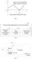
- the actual rotation speed of the motor is less than the upper limit and greater than the lower limit of the reference speed of the motor.
- the actual rotation speed of the motor increases rapidly and exceeds the upper limit of the reference speed of the motor, causing the front wheels to slip.
- the reference rotation speed of the power mechanism can be determined according to the corrected rear-wheel rotation speed n' and the preset speed ratio.
- the preset speed ratio may be specifically a ratio between the rear-wheel rotation speed and the rotation speed of the power mechanism. For example, if the preset speed ratio is b, the reference rotation speed of the power mechanism may be n' / b.
- the method may further include: generating a torque adjustment request when the vehicle operating condition meets a preset condition.
- the vehicle operating condition may include one or more of a gear position, a reference driving speed, an opening degree of the accelerator pedal, a steering wheel angle, a road slope, and a wheel speed difference between the rotation speed of the left front wheel and the rotation speed of the right front wheel.
- the vehicle operating condition meeting the preset condition may include one or more of the following situations: the gear position is a forward gear position, the reference driving speed is within a preset vehicle speed range, the opening degree of the accelerator pedal is within a preset opening range, the steering wheel angle is less than a preset angle threshold, the road slope is less than a preset slope threshold, and the wheel speed difference between the rotation speed of the left front wheel and the rotation speed of the right front wheel is less than a speed threshold.
- a torque adjustment request is generated, the torque adjustment flag is activated, and then steps 201 to 203 are executed, in which the output torque is adjusted when the front wheels of the vehicle are determined to be slipping. If the vehicle operating condition does not meet the above-mentioned preset conditions, no torque adjustment request is generated, the torque adjustment flag is not activated, and steps 201 to 203 are not executed accordingly.
- preset vehicle speed range preset opening range
- preset turning angle threshold preset slope threshold
- speed threshold are not specifically limited in the embodiments of the present application. Those skilled in the art can set them according to actual needs, which are all within the protection scope of the present application.
- step 202 a ratio of the actual rotation speed to the reference rotation speed of the power mechanism is calculated.
- the above ratio is configured to characterize the relationship between the actual rotation speed of the power mechanism and the reference speed thereof.
- step 203 the output torque of the power mechanism is reduced when the above ratio is greater than or equal to a preset threshold.
- the above-mentioned preset threshold value may be calibrated based on experimental data. If the above-mentioned ratio is greater than or equal to the above-mentioned preset threshold value, it means that the output torque of the power mechanism is too large at this moment, and the output torque of the power mechanism needs to be reduced to suppress the rapid increase of the front-wheel rotation speed and alleviate the extent of slipping of the front wheels. If the above-mentioned ratio is less than the above-mentioned preset threshold value, it means that the output torque of the power mechanism is large at this moment, but it has little effect on the driving of the vehicle, and the output torque of the power mechanism may not be adjusted.
- the above-mentioned reduction in the output torque of the power mechanism may specifically include: determining a weighting coefficient of the torque based on the above-mentioned ratio, where the ratio is inversely proportional to the weighting coefficient of the torque, and the weighting coefficient of the torque is configured to characterize the degree of adjustment of the output torque of the power mechanism; and adjusting the output torque of the power mechanism based on the weighting coefficient of the torque.
- the weighting coefficient of the torque may be a value in the range of (0, 1).
- the weighting coefficient of the torque is multiplied by the output torque of the power mechanism to calculate the adjusted output torque, and then the output torque of the power mechanism is adjusted according to the calculated output torque, thereby reducing the output torque of the power mechanism to prevent the actual rotation speed of the power mechanism from increasing rapidly and to alleviate the extent of front wheel slip.
- the weighting coefficient of the torque corresponding to the above ratio can be determined based on a preset data table, which stores a correspondence between the ratio and the weighting coefficient of the torque. The larger the ratio, the smaller the corresponding weighting coefficient of the torque.
- the ratio and the weighting coefficient of the torque may be reciprocals of each other, and the weighting coefficient of the torque may be used to adjust the output torque of the power mechanism to an output torque of the power mechanism when the front wheels of the vehicle do not slip.
- the reciprocal of the ratio may be smaller than the weighting coefficient of the torque, and the output torque of the power mechanism can be brought closer to an output torque of the power mechanism when the front wheels of the vehicle do not slip through the weighting coefficient of the torque.
- the above-mentioned preset threshold may be determined based on experiments and will not be described in detail herein.
- the reference rotation speed of the power mechanism at this moment is determined by the rear-wheel rotation speed and the reference driving speed, thereby reflecting the normal rotation speed of the power mechanism. Afterwards, the ratio of the reference speed to the actual rotation speed of the power mechanism is calculated. A ratio greater than or equal to the preset threshold indicates that the actual rotation speed of the power mechanism may be greatly increased due to the above-mentioned slip phenomenon. At this moment, the output torque of the power mechanism can be reduced to prevent the actual rotation speed of the power mechanism from increasing rapidly, thereby alleviating the extent of slipping of the front wheels.
- FIG. 4 shows a schematic diagram of the structure of a torque control apparatus for a front-drive vehicle provided in an embodiment of the present application. For ease of illustration, only the parts related to the embodiment of the present application are shown, which are described in detail as follows:
- a torque control apparatus 400 for a front-drive vehicle may include a reference speed determination module 401, a ratio calculation module 402, and an output torque adjustment module 403.
- the reference speed determination module 401 is configured to determine a reference rotation speed of the power mechanism based on a rear-wheel rotation speed and a reference driving speed in response to a torque adjustment request.
- the torque adjustment request is generated based on a vehicle operating condition.
- the ratio calculation module 402 is configured to calculate a ratio of an actual rotation speed to the reference rotation speed of the power mechanism.
- the output torque adjustment module 403 is configured to reduce an output torque of the power mechanism when the ratio is greater than or equal to a preset threshold.
- the reference speed determination module 401 may include: a vehicle-speed offset determination unit, configured to determine a vehicle-speed offset corresponding to the reference driving speed and the vehicle operating condition through a preset data table, where the preset data table contains a correspondence between the reference driving speed, the vehicle operating condition, and the vehicle-speed offset; a correction unit, configured to correct the reference driving speed according to the vehicle-speed offset; and a reference speed determination unit, configured to determine the reference rotation speed of the power mechanism according to a rear-wheel rotation speed and the corrected reference driving speed.
- the vehicle operating condition may include an opening degree of the accelerator pedal, a steering wheel angle, a road slope, and a wheel speed difference, where the wheel speed difference is the difference between the rotation speed of the left front wheel and the rotation speed of the right front wheel.
- the vehicle-speed offset determination unit may be specifically configured to: determine a first vehicle-speed offset component corresponding to the opening degree of the accelerator pedal, a second vehicle-speed offset component corresponding to the steering wheel angle, a third vehicle-speed offset component corresponding to the road slope, and a fourth vehicle-speed offset component corresponding to the wheel speed difference through the preset data table; and determine the vehicle-speed offset based on the first vehicle-speed offset component to the fourth vehicle-speed offset component.
- the reference speed determination unit may be specifically configured to: determine a corrected rear-wheel rotation speed based on the corrected reference driving speed and a rear-wheel radius; determine the reference rotation speed of the power mechanism based on the corrected rear-wheel rotation speed and a preset speed ratio, where the preset speed ratio characterizes the relationship between the rear-wheel rotation speed and the rotation speed of the power mechanism.
- the output torque adjustment module 403 may be specifically configured to: determine a weighting coefficient of the torque based on the above ratio, where the above ratio is inversely proportional to the weighting coefficient of the torque, and the weighting coefficient of the torque is used to characterize a degree of adjustment of the output torque of the power mechanism; and adjust the output torque of the power mechanism based on the weighting coefficient of the torque.
- the torque control apparatus 400 for a front-drive vehicle may further include: a torque adjustment request generation module, configured to generate a torque adjustment request when the vehicle operating condition meets a preset condition.
- the vehicle operating condition may include one or more of a gear position, a reference driving speed, an opening degree of the accelerator pedal, a steering wheel angle, a road slope, and a wheel speed difference between the rotation speed of a left front wheel and the rotation speed of a right front wheel.
- the vehicle operating condition meeting the preset condition includes one or more of the following situations: the gear position is a forward gear position, the reference driving speed is in a preset vehicle speed range, the opening degree of the accelerator pedal is in a preset opening area, the steering wheel angle is less than a preset angle threshold, the road slope is less than a preset slope threshold, and the wheel speed difference between the rotation speed of the left front wheel and the rotation speed of the right front wheel is less than a speed threshold.
- An embodiment of the present application provides a vehicle, including an electronic device, which includes a memory, a processor, and a computer program stored in the memory and executable on the processor.
- the computer program When executed by the processor, the computer program implements the steps of the torque control method for a front-drive vehicle in any of the above-mentioned embodiments, such as steps 201 to 203 shown in FIG. 2 .
- An embodiment of the present application also provides a computer program product having a program code, which, when running in a corresponding processor, controller, computing device, or terminal, executes the steps of the torque control method for a front-drive vehicle in any of the above-mentioned embodiments, such as steps 201 to 203 shown in FIG. 2 .
- the dedicated processor may include an application specific integrated circuit (ASIC), a reduced instruction set computer (RISC), and/or a field programmable gate array (FPGA).
- ASIC application specific integrated circuit
- RISC reduced instruction set computer
- FPGA field programmable gate array
- the proposed methods and apparatus are preferably implemented as a combination of hardware and software.
- the software is preferably installed on a program storage device as an application. It is typically based on a machine with a computer platform having hardware, such as one or more central processing units (CPUs), random access memories (RAMs), and one or more input/output (I/O) interfaces.
- CPUs central processing units
- RAMs random access memories
- I/O input/output
- An operating system is also typically installed on the computer platform.
- the various processes and functions described herein may be part of an application, or a portion thereof may be executed by an operating system.
- FIG. 5 is a schematic diagram of an electronic device provided in an embodiment of the present application.
- the electronic device 500 of this embodiment includes: a processor 501, a memory 502, and a computer program 503 stored in the memory 502 and executable on the processor 501.
- the computer program 503 When executed by the processor 501, the computer program 503 implements the steps of the torque control method for a front-drive vehicle in any of the above-mentioned embodiments, such as steps 201 to 203 shown in FIG. 2 .
- the processor 501 executes the computer program 503 the functions of the modules/units in the above-mentioned device embodiments are implemented, such as the functions of the modules/units 401 to 403 shown in FIG. 4 .
- the computer program 503 may be divided into one or more modules/units, which are stored in the memory 502 and executed by the processor 501 to complete/implement the solution provided in the present application.
- the one or more modules/units may be a series of computer program instruction segments capable of completing specific functions, which are used to describe the execution process of the computer program 503 in the electronic device 500.
- the computer program 503 may be divided into modules/units 401 to 403 as shown in FIG. 4 .
- the electronic device 500 may be a computing device such as a vehicle controller, a mobile phone, a laptop, a PDA, and a cloud server.
- the electronic device 500 may include, but is not limited to, a processor 501 and a memory 502.
- FIG. 5 is only an example of the electronic device 500 and does not constitute a limitation on the electronic device 500.
- the electronic device 500 may include more or fewer components than illustrated, or may combine certain components, or different components.
- the electronic device 500 may also include input and output devices, network access devices, buses, and the like.
- the processor 501 may be a central processing unit (CPU), or other general-purpose processors, digital signal processors (DSP), application-specific integrated circuits (ASIC), field-programmable gate arrays (FPGA), or other programmable logic devices, discrete gate or transistor logic devices, discrete hardware components, and the like.
- DSP digital signal processors
- ASIC application-specific integrated circuits
- FPGA field-programmable gate arrays
- a general-purpose processor may be a microprocessor or any conventional processor, and the like.
- the memory 502 may be an internal storage unit of the electronic device 500, such as a hard disk or memory of the electronic device 500.
- the memory 502 may also be an external storage device of the electronic device 500, such as a plug-in hard disk, a smart media card (SMC), a secure digital (SD) card, a flash card, and the like equipped on the electronic device 500. Further, the memory 502 may also include both an internal storage unit of the electronic device 500 and an external storage device.
- the memory 502 is configured to store the computer program and other programs and data required by the electronic device.
- the memory 502 may also be configured to temporarily store data that has been output or is to be output.
- the disclosed devices/terminals and methods can be implemented in other ways.
- the device/terminal embodiments described above are only schematic.
- the division of the modules or units is only a logical function division. There may be other division methods in actual implementation, such as multiple units or components can be combined or integrated into another system, or some features can be ignored or not executed.
- Another point is that the mutual coupling or direct coupling or communication connection shown or discussed can be through some interfaces, indirect coupling or communication connection of devices or units, which can be electrical, mechanical or other forms.
- the units described as separate components may or may not be physically separated, and the components shown as units may or may not be physical units, that is, they may be located in one place or distributed on multiple network units. Some or all of the units may be selected according to actual needs to achieve the purpose of the solution of this embodiment.
- each functional unit in each embodiment of the present application may be integrated into one processing unit, or each unit may exist physically separately, or two or more units may be integrated into one unit.
- the above-mentioned integrated unit may be implemented in the form of hardware or in the form of software functional units.
- the integrated module/unit is implemented in the form of a software functional unit and sold or used as an independent product, it can be stored in a computer-readable storage medium.
- the present application implements all or part of the processes in the above-mentioned embodiment method, and can also be completed by instructing the relevant hardware through a computer program.
- the computer program can be stored in a non-volatile computer-readable storage medium.
- the steps of the above-mentioned torque control method for a front-drive vehicle embodiments can be implemented.
- the computer program includes computer program code, and the computer program code can be in source code form, object code form, executable file, or some intermediate form.
- the computer-readable storage medium can include: any entity or device that can carry the computer program code, recording medium, U disk, mobile hard disk, disk, optical disk, computer memory, read-only memory (ROM), random access memory (RAM), electric carrier signal, telecommunication signal and software distribution medium. It should be noted that the content contained in the computer-readable storage medium can be appropriately increased or decreased according to the requirements of legislation and patent practice in the jurisdiction. For example, in some jurisdictions, according to legislation and patent practice, computer-readable storage media does not include electrical carrier signals and telecommunication signals.
Landscapes
- Engineering & Computer Science (AREA)
- Transportation (AREA)
- Mechanical Engineering (AREA)
- Chemical & Material Sciences (AREA)
- Combustion & Propulsion (AREA)
- Automation & Control Theory (AREA)
- Arrangement And Driving Of Transmission Devices (AREA)
Abstract
Description
- This patent application claims priority to Chinese patent application No.
CN202210018323.8 filed on January 7, 2022 - The present application relates to the field of vehicle technology, and in particular, to a torque control method and apparatus for a front-drive vehicle, and a vehicle.
- A front-drive vehicle refers to a vehicle that is driven by the front wheels. During the traveling of a front-drive vehicle, for example, when the vehicle is accelerating or braking to slow down over a speed bump, the front wheels will slip briefly. Since the friction coefficient of the speed bump is smaller than the friction coefficient of the road surface, the adhesion of the front wheels will decrease when the front wheels of the vehicle pass over the speed bump. Moreover, the vehicle is in the state of acceleration or braking deceleration. For example, if the accelerator pedal is kept at a certain position, the reduction in adhesion will cause the rotation speed of the front axle to soar rapidly, resulting in front-wheel slippage. When the front wheels slip, the vehicle body will skid to a certain extent, resulting in instability of the vehicle body.
- Although the vehicle has an ESP system (electronic stability program), which is able to intervene to keep the vehicle stable in the event of wheel slip, the ESP system does not intervene to keep the vehicle stable during this period as the vehicle's travel time on a speed bump is usually very short.
- The present application provides a torque control method and apparatus for a front-drive vehicle, and a vehicle using the same, which can reduce the rotation speed of the front axle of the power mechanism and prevent the rotation speed of the front axle from increasing rapidly, thereby alleviating the degree of slippage of the vehicle's front wheels and solving the problem that the ESP system cannot intervene in a short period to maintain the stability of the vehicle body when the front wheels of the vehicle slip.
- In a first aspect, the present application provides a torque control method for a front-drive vehicle, the method including: determining a reference speed of a power mechanism based on a rear-wheel rotation speed and a reference driving speed in response to a torque adjustment request, the torque adjustment request being generated based on a vehicle operating condition; calculating a ratio of an actual rotation speed to the reference rotation speed of the power mechanism; and reducing an output torque of the power mechanism when the ratio is greater than or equal to a preset threshold.
- In a possible implementation, the step of determining a reference speed of a power mechanism based on a rear-wheel rotation speed and a reference driving speed includes: determining a vehicle-speed offset corresponding to the reference driving speed and the vehicle operating condition through a preset data table, the above-mentioned preset data table containing a correspondence between the reference driving speed, the vehicle operating condition, and the vehicle-speed offset; correcting the reference driving speed according to the vehicle-speed offset; and determining the reference rotation speed of the power mechanism according to the rear-wheel rotation speed and a corrected reference driving speed.
- In a possible implementation, the above-mentioned vehicle operating condition includes an opening degree of an accelerator pedal, a steering wheel angle, a road slope, and a wheel speed difference, where the wheel speed difference is a difference between a rotation speed of a left front wheel and a rotation speed of a right front wheel. The step of determining a vehicle-speed offset corresponding to the reference driving speed and the vehicle operating condition through a preset data table includes: determining a first vehicle-speed offset component corresponding to the opening degree of the accelerator pedal, a second vehicle-speed offset component corresponding to the steering wheel angle, a third vehicle-speed offset component corresponding to the road slope, and a fourth vehicle-speed offset component corresponding to the wheel speed difference through the preset data table; and determining the vehicle-speed offset based on the first vehicle-speed offset component to the fourth vehicle-speed offset component.
- In a possible implementation, the step of correcting the reference driving speed according to the vehicle-speed offset includes: correcting the reference driving speed based on v'= (1+a)·v, where a is the vehicle-speed offset, v is the reference driving speed, and v' is the corrected reference driving speed.
- In a possible implementation, the step of determining the reference rotation speed of the power mechanism according to the rear-wheel rotation speed and the corrected reference driving speed includes: determining a corrected rear-wheel rotation speed according to the corrected reference driving speed and a rear-wheel radius; determining the reference rotation speed of the power mechanism based on the corrected rear-wheel rotation speed and a preset speed ratio, where the preset speed ratio characterizes the relationship between the rear-wheel rotation speed and a rotation speed of the power mechanism.
- In one possible implementation, the step of reducing an output torque of the power mechanism includes: determining a weighting coefficient of the torque based on the above-mentioned ratio, where the ratio is inversely proportional to the weighting coefficient of the torque, and the weighting coefficient of the torque is configured to characterize a degree of adjustment of the output torque of the power mechanism; and adjusting the output torque of the power mechanism based on the weighting coefficient of the torque.
- In a possible implementation, before responding to the torque adjustment request, the method further includes: generating the torque adjustment request when the vehicle operating condition meets a preset condition. The vehicle operating condition may include one or more of a gear position, a reference driving speed, an opening degree of the accelerator pedal, a steering wheel angle, a road slope, and a wheel speed difference between the rotation speed of the left front wheel and the rotation speed of the right front wheel. The vehicle operating condition meeting the preset condition includes one or more of the following situations: the gear position is a forward gear position, the reference driving speed is within a preset vehicle speed range, the opening degree of the accelerator pedal is within a preset position area, the steering wheel angle is less than a preset angle threshold, the road slope is less than a preset slope threshold, and the wheel speed difference between the rotation speed of the left front wheel and the rotation speed of the right front wheel is less than a speed threshold.
- In a second aspect, the present application provides a torque control apparatus for a front-drive vehicle, including: a determination module, configured to determine a reference speed of a power mechanism based on a rear-wheel rotation speed and a reference driving speed in response to a torque adjustment request, the torque adjustment request being generated based on a vehicle operating condition; a calculation module, configured to calculate a ratio of an actual rotation speed to a reference rotation speed of the power mechanism; and an output torque adjustment module, configured to reduce the output torque of the power mechanism when the ratio is greater than or equal to a preset threshold.
- In a third aspect, the present application provides an electronic device including a memory, a processor, and a computer program stored in the memory and executable on the processor. When executed by the processor, the computer program implements the steps of the method described in the first aspect or any possible implementation of the first aspect.
- In a fourth aspect, the present application provides a vehicle including an electronic device, the electronic device including a memory, a processor, and a computer program stored in the memory and executable on the processor. When executed by the processor, the computer program implements the steps of the method described in the first aspect or any possible implementation of the first aspect.
- In a fifth aspect, the present application provides a non-volatile computer-readable storage medium, the computer-readable storage medium storing a computer program, and when executed by a processor, the computer program implements the steps of the method described in the first aspect or any possible implementation of the first aspect.
- In a sixth aspect, the present application provides a computer program product having a program code, which, when executed in a corresponding processor, controller, computing device, or electronic device, executes the steps of the method described in the first aspect or any possible implementation of the first aspect.
- The present application provides such as a torque control method and apparatus for a front-drive vehicle, and a vehicle using the same. When the front-drive vehicle accelerates or brakes to decelerate through a speed bump, for example, the adhesion of the front wheel is reduced, which causes the rotation speed of the power mechanism (such as a motor or an engine) to increase significantly, and the front wheel will slip. In the embodiment of the present application, in view that the rear wheels of the front-drive vehicle will not experience the above-mentioned slip phenomenon, the reference rotation speed of the power mechanism at this time is determined by the rear-wheel rotation speed and the reference driving speed, thereby reflecting the normal rotation speed of the power mechanism. Afterwards, the ratio of the reference speed to the actual rotation speed of the power mechanism is calculated. When the ratio is greater than or equal to the preset threshold, it indicates that the actual rotation speed of the power mechanism may be significantly increased due to the above-mentioned slip phenomenon. Accordingly, the output torque of the power mechanism can be reduced to prevent the actual rotation speed of the power mechanism from increasing rapidly, thereby alleviating the extent of slipping of the front wheels.
- In order to more clearly illustrate the technical solutions in the embodiments of the present application, the drawings used in the description of the embodiments or the prior art will be briefly introduced below. Apparently, the drawings described below are merely some embodiments of the present application. For one of ordinary skill in the art, other drawings can be obtained based on these drawings without any creative effort.
-
FIG. 1 is a schematic diagram of an application scenario of a torque control method for a front-drive vehicle provided in an embodiment of the present application; -
FIG. 2 is a schematic flow chart of the torque control method for a front-drive vehicle provided in an embodiment of the present application; -
FIG. 3 is a schematic diagram of a reference speed and an actual rotation speed of a motor provided in an embodiment of the present application; -
FIG. 4 is a schematic diagram of the structure of a torque control apparatus for a front-drive vehicle provided in an embodiment of the present application; and -
FIG. 5 is a schematic diagram of an electronic device provided in an embodiment of the present application. - In the following description, specific details such as specific system structures, technologies, and the like are provided for the purpose of explanation rather than limitation, so as to provide a thorough understanding of the embodiments of the present application. However, it should be understood by those skilled in the art that the present application may also be implemented in other embodiments without these specific details. In other cases, detailed descriptions of well-known systems, devices, circuits, and methods are omitted to prevent unnecessary details from obstructing the description of the present application.
- In order to make the purpose, technical solutions and advantages of the present application clearer, specific embodiments will be described below in conjunction with the accompanying drawings.
-
FIG. 1 shows an application scenario of the torque control method for a front-drive vehicle provided by an embodiment of the present application. Referring toFIG. 1 , in this application scenario, a front-drive vehicle is traveling on a road, for example, when the front-drive vehicle is accelerating or braking to decelerate over a speed bump, the adhesion of the front wheel is reduced, which results in a significant increase in the rotation speed of the power mechanism (such as a motor or an engine), and the front wheel will slip. - The following is an example of a vehicle accelerating over a speed bump. When the vehicle accelerates (for example, the opening degree of the accelerator pedal is 30%) and travels over a speed bump, the friction coefficient of the road surface is relatively large, the vehicle has a strong grip on the road surface, and the front wheels of the vehicle usually do not slip. When the front wheels of the vehicle travel over the speed bump, because the friction coefficient of the speed bump is smaller than the friction coefficient of the road surface, the adhesion is reduced. If the output torque of the motor remains unchanged, the front-wheel rotation speed will rise rapidly, causing the fronts wheel to slip. In addition, when the front-wheel rotation speed rises rapidly, abnormal noise may also be generated from the front suspension of the vehicle.
- In the embodiment of the present application, considering that the rear wheels of a front-drive vehicle will not experience the above-mentioned slip phenomenon, here, the reference rotation speed of the power mechanism is determined by the rear-wheel rotation speed and the reference driving speed, thereby reflecting the normal rotation speed of the power mechanism. Afterwards, the ratio of the reference speed to the actual rotation speed of the power mechanism is calculated. When the ratio is greater than or equal to a preset threshold, it indicates that the actual rotation speed of the power mechanism may be greatly increased due to the above-mentioned slip phenomenon. At this time, the output torque of the power mechanism can be reduced to prevent the actual rotation speed of the power mechanism from increasing rapidly, thereby alleviating the degree of slippage of the front wheels.
- In conjunction with
FIG. 1 , the front wheel slippage caused by acceleration or braking of the vehicle when traveling over a speed bump is taken as an example to describe the torque control method for a front-drive vehicle provided in the embodiment of the present application. - Referring to
FIG. 2 , a flowchart of the torque control method for a front-drive vehicle according to an embodiment of the present application is shown, which is described in detail below. - In
step 201, a reference speed of a power mechanism is determined based on a rear-wheel rotation speed and a reference driving speed in response to a torque adjustment request. - In this step, the torque adjustment request is generated based on the vehicle operating conditions, and the reference speed may be the rotation speed of the power mechanism calculated by a vehicle controller, which is different from the actual rotation speed of the power mechanism. The actual rotation speed at this time will increase rapidly, while the reference speed can reflect the normal rotation speed of the power mechanism when the front wheels are not slipping. The vehicle controller may be an HCU (hybrid control unit) or other controllers, which are not limited in the embodiments of the present application.
- The rear-wheel rotation speed can be obtained by a wheel speed sensor disposed on the rear wheels. Since the rear wheels include a left rear wheel and a right rear wheel, the rotation speed of the left rear wheel and the rotation speed of the right rear wheel can be averaged to balance the difference in wheel speeds of the two rear wheels to more accurately determine the rear-wheel rotation speed. The rear-wheel radius is a preset value and will not be described in detail herein.
- In some embodiments, the above-mentioned determination of the reference rotation speed of the power mechanism based on the rear-wheel rotation speed and the reference driving speed may include: determining a vehicle-speed offset corresponding to the reference driving speed and the vehicle operating condition through a preset data table, where the preset data table contains the correspondence between the reference driving speed, the vehicle operating condition and the vehicle-speed offset; correcting the reference driving speed according to the vehicle-speed offset; and determining the reference rotation speed of the power mechanism according to the rear-wheel rotation speed and the corrected reference driving speed.
- As an example, the reference driving speed may be determined and sent to the vehicle controller by the ESP system. For example, the ESP system may determine the reference driving speed of the vehicle by multiplying the rear-wheel rotation speed by the rear-wheel radius. Specifically, the reference driving speed may be determined by v = nπr, where v is the reference driving speed, n is the rear-wheel rotation speed, and r is the rear-wheel radius.
- In addition, the reference driving speed may also be determined by the vehicle controller through the product of the rear-wheel rotation speed and the rear-wheel radius.
- Exemplarily, the vehicle operating condition may include an opening degree of the accelerator pedal, a steering wheel angle, a road slope, and a wheel speed difference, where the wheel speed difference is a difference between the rotation speed of the left front wheel and the rotation speed of the right front wheel. Correspondingly, the above-mentioned determination of the vehicle-speed offset corresponding to the reference driving speed and the vehicle operating condition through a preset data table may include: determining a first vehicle-speed offset component corresponding to the opening degree of the accelerator pedal, a second vehicle-speed offset component corresponding to the steering wheel angle, a third vehicle-speed offset component corresponding to the road slope, and a fourth vehicle-speed offset component corresponding to the wheel speed difference through a preset data table; and determining the vehicle-speed offset based on the first vehicle-speed offset component to the fourth vehicle-speed offset component.
- For example, the first vehicle-speed offset component, the second vehicle-speed offset component, the third vehicle-speed offset component, and the fourth vehicle-speed offset component may be added up to obtain the vehicle-speed offset. The first vehicle-speed offset component, the second vehicle-speed offset component, the third vehicle-speed offset component, and the fourth vehicle-speed offset component are all positive numbers less than 1, and the calculated vehicle-speed offset is within the range of (0, 1).
- Exemplarily, the above-mentioned correction of the reference driving speed according to the vehicle-speed offset may include: correcting the reference driving speed based on v '=(1 + a)·v, where a is the vehicle-speed offset, v is the reference driving speed, and v' is the corrected reference driving speed.
- Exemplarily, the above-mentioned determination of the reference rotation speed of the power mechanism based on the rear-wheel rotation speed and the corrected reference driving speed may include: determining the corrected rear-wheel rotation speed based on the corrected reference driving speed and the rear-wheel radius; determining the reference rotation speed of the power mechanism based on the corrected rear-wheel rotation speed and a preset speed ratio, where the preset speed ratio characterizes a relationship between the rear-wheel rotation speed and the rotation speed of the power mechanism.
- As shown in
FIG. 3 , under normal operating conditions, the actual rotation speed of the motor is less than the upper limit and greater than the lower limit of the reference speed of the motor. Under conditions when traveling over a speed bump, the actual rotation speed of the motor increases rapidly and exceeds the upper limit of the reference speed of the motor, causing the front wheels to slip. - Specifically, the product of the corrected reference driving speed and the rear-wheel radius can be calculated to determine the corrected rear-wheel rotation speed, n'= v'/πr. Then, the reference rotation speed of the power mechanism can be determined according to the corrected rear-wheel rotation speed n' and the preset speed ratio. The preset speed ratio may be specifically a ratio between the rear-wheel rotation speed and the rotation speed of the power mechanism. For example, if the preset speed ratio is b, the reference rotation speed of the power mechanism may be n'/b.
- In some embodiments, before
step 201, the method may further include: generating a torque adjustment request when the vehicle operating condition meets a preset condition. The vehicle operating condition may include one or more of a gear position, a reference driving speed, an opening degree of the accelerator pedal, a steering wheel angle, a road slope, and a wheel speed difference between the rotation speed of the left front wheel and the rotation speed of the right front wheel. The vehicle operating condition meeting the preset condition may include one or more of the following situations: the gear position is a forward gear position, the reference driving speed is within a preset vehicle speed range, the opening degree of the accelerator pedal is within a preset opening range, the steering wheel angle is less than a preset angle threshold, the road slope is less than a preset slope threshold, and the wheel speed difference between the rotation speed of the left front wheel and the rotation speed of the right front wheel is less than a speed threshold. - Exemplarily, when the vehicle operating condition meets the above-mentioned preset conditions, a torque adjustment request is generated, the torque adjustment flag is activated, and then steps 201 to 203 are executed, in which the output torque is adjusted when the front wheels of the vehicle are determined to be slipping. If the vehicle operating condition does not meet the above-mentioned preset conditions, no torque adjustment request is generated, the torque adjustment flag is not activated, and steps 201 to 203 are not executed accordingly.
- It should be noted that the above-mentioned preset vehicle speed range, preset opening range, preset turning angle threshold, preset slope threshold, and speed threshold are not specifically limited in the embodiments of the present application. Those skilled in the art can set them according to actual needs, which are all within the protection scope of the present application.
- In
step 202, a ratio of the actual rotation speed to the reference rotation speed of the power mechanism is calculated. - The above ratio is configured to characterize the relationship between the actual rotation speed of the power mechanism and the reference speed thereof. The larger the above ratio is, the more the actual rotation speed of the power mechanism deviates from the normal speed when the front wheel is not slipping. The closer the above ratio is to 1, the closer the actual rotation speed of the power mechanism is to the normal speed when the front wheel is not slipping. Therefore, by calculating the above ratio, it is possible to determine whether the actual rotation speed of the power mechanism deviates from the normal speed and the degree of deviation from the normal speed, thereby determining whether the output torque of the power mechanism needs to be controlled to alleviate the extent of slipping of the front wheels.
- In
step 203, the output torque of the power mechanism is reduced when the above ratio is greater than or equal to a preset threshold. - The above-mentioned preset threshold value may be calibrated based on experimental data. If the above-mentioned ratio is greater than or equal to the above-mentioned preset threshold value, it means that the output torque of the power mechanism is too large at this moment, and the output torque of the power mechanism needs to be reduced to suppress the rapid increase of the front-wheel rotation speed and alleviate the extent of slipping of the front wheels. If the above-mentioned ratio is less than the above-mentioned preset threshold value, it means that the output torque of the power mechanism is large at this moment, but it has little effect on the driving of the vehicle, and the output torque of the power mechanism may not be adjusted.
- Exemplarily, the above-mentioned reduction in the output torque of the power mechanism may specifically include: determining a weighting coefficient of the torque based on the above-mentioned ratio, where the ratio is inversely proportional to the weighting coefficient of the torque, and the weighting coefficient of the torque is configured to characterize the degree of adjustment of the output torque of the power mechanism; and adjusting the output torque of the power mechanism based on the weighting coefficient of the torque.
- As an example, the weighting coefficient of the torque may be a value in the range of (0, 1). The weighting coefficient of the torque is multiplied by the output torque of the power mechanism to calculate the adjusted output torque, and then the output torque of the power mechanism is adjusted according to the calculated output torque, thereby reducing the output torque of the power mechanism to prevent the actual rotation speed of the power mechanism from increasing rapidly and to alleviate the extent of front wheel slip.
- In some embodiments, the weighting coefficient of the torque corresponding to the above ratio can be determined based on a preset data table, which stores a correspondence between the ratio and the weighting coefficient of the torque. The larger the ratio, the smaller the corresponding weighting coefficient of the torque.
- For example, the ratio and the weighting coefficient of the torque may be reciprocals of each other, and the weighting coefficient of the torque may be used to adjust the output torque of the power mechanism to an output torque of the power mechanism when the front wheels of the vehicle do not slip.
- For another example, the reciprocal of the ratio may be smaller than the weighting coefficient of the torque, and the output torque of the power mechanism can be brought closer to an output torque of the power mechanism when the front wheels of the vehicle do not slip through the weighting coefficient of the torque.
- The above-mentioned preset threshold may be determined based on experiments and will not be described in detail herein.
- In the above-mentioned torque control method for a front-drive vehicle, taking into account that the rear wheels of the front-drive vehicle will not experience the above-mentioned slip phenomenon. Therefore, the reference rotation speed of the power mechanism at this moment is determined by the rear-wheel rotation speed and the reference driving speed, thereby reflecting the normal rotation speed of the power mechanism. Afterwards, the ratio of the reference speed to the actual rotation speed of the power mechanism is calculated. A ratio greater than or equal to the preset threshold indicates that the actual rotation speed of the power mechanism may be greatly increased due to the above-mentioned slip phenomenon. At this moment, the output torque of the power mechanism can be reduced to prevent the actual rotation speed of the power mechanism from increasing rapidly, thereby alleviating the extent of slipping of the front wheels.
- It should be understood that the size of the serial numbers of the steps in the above embodiments does not mean the order of execution. The execution order of each process should be determined by its function and internal logic, and should not constitute any limitation on the implementation process of the embodiments of the present application.
- The following is an embodiment of the device of the present application. For details that are not specifically described, please refer to the corresponding method embodiment described above.
-
FIG. 4 shows a schematic diagram of the structure of a torque control apparatus for a front-drive vehicle provided in an embodiment of the present application. For ease of illustration, only the parts related to the embodiment of the present application are shown, which are described in detail as follows:
As shown inFIG. 4 , atorque control apparatus 400 for a front-drive vehicle may include a referencespeed determination module 401, aratio calculation module 402, and an outputtorque adjustment module 403. - The reference
speed determination module 401 is configured to determine a reference rotation speed of the power mechanism based on a rear-wheel rotation speed and a reference driving speed in response to a torque adjustment request. The torque adjustment request is generated based on a vehicle operating condition. Theratio calculation module 402 is configured to calculate a ratio of an actual rotation speed to the reference rotation speed of the power mechanism. The outputtorque adjustment module 403 is configured to reduce an output torque of the power mechanism when the ratio is greater than or equal to a preset threshold. - In one possible implementation, the reference
speed determination module 401 may include: a vehicle-speed offset determination unit, configured to determine a vehicle-speed offset corresponding to the reference driving speed and the vehicle operating condition through a preset data table, where the preset data table contains a correspondence between the reference driving speed, the vehicle operating condition, and the vehicle-speed offset; a correction unit, configured to correct the reference driving speed according to the vehicle-speed offset; and a reference speed determination unit, configured to determine the reference rotation speed of the power mechanism according to a rear-wheel rotation speed and the corrected reference driving speed. - In some embodiments, the vehicle operating condition may include an opening degree of the accelerator pedal, a steering wheel angle, a road slope, and a wheel speed difference, where the wheel speed difference is the difference between the rotation speed of the left front wheel and the rotation speed of the right front wheel. The vehicle-speed offset determination unit may be specifically configured to: determine a first vehicle-speed offset component corresponding to the opening degree of the accelerator pedal, a second vehicle-speed offset component corresponding to the steering wheel angle, a third vehicle-speed offset component corresponding to the road slope, and a fourth vehicle-speed offset component corresponding to the wheel speed difference through the preset data table; and determine the vehicle-speed offset based on the first vehicle-speed offset component to the fourth vehicle-speed offset component.
- In some embodiments, the correction unit may be specifically configured to correct the reference driving speed based on v'= (1+ a)·v, where a is the vehicle-speed offset, v is the reference driving speed, and v' is the corrected reference driving speed.
- In some embodiments, the reference speed determination unit may be specifically configured to: determine a corrected rear-wheel rotation speed based on the corrected reference driving speed and a rear-wheel radius; determine the reference rotation speed of the power mechanism based on the corrected rear-wheel rotation speed and a preset speed ratio, where the preset speed ratio characterizes the relationship between the rear-wheel rotation speed and the rotation speed of the power mechanism.
- In one possible implementation, the output
torque adjustment module 403 may be specifically configured to: determine a weighting coefficient of the torque based on the above ratio, where the above ratio is inversely proportional to the weighting coefficient of the torque, and the weighting coefficient of the torque is used to characterize a degree of adjustment of the output torque of the power mechanism; and adjust the output torque of the power mechanism based on the weighting coefficient of the torque. - In a possible implementation, the
torque control apparatus 400 for a front-drive vehicle may further include: a torque adjustment request generation module, configured to generate a torque adjustment request when the vehicle operating condition meets a preset condition. The vehicle operating condition may include one or more of a gear position, a reference driving speed, an opening degree of the accelerator pedal, a steering wheel angle, a road slope, and a wheel speed difference between the rotation speed of a left front wheel and the rotation speed of a right front wheel. The vehicle operating condition meeting the preset condition includes one or more of the following situations: the gear position is a forward gear position, the reference driving speed is in a preset vehicle speed range, the opening degree of the accelerator pedal is in a preset opening area, the steering wheel angle is less than a preset angle threshold, the road slope is less than a preset slope threshold, and the wheel speed difference between the rotation speed of the left front wheel and the rotation speed of the right front wheel is less than a speed threshold. - It should be noted that, the technical means and technical effects not described in detail in the embodiments of the device of the present application can be referred to the corresponding technical means and technical effects in the embodiments of the method of the present application. It should be considered that the embodiments of the device of the present application have clearly recorded the contents not described in detail after this description.
- An embodiment of the present application provides a vehicle, including an electronic device, which includes a memory, a processor, and a computer program stored in the memory and executable on the processor. When executed by the processor, the computer program implements the steps of the torque control method for a front-drive vehicle in any of the above-mentioned embodiments, such as
steps 201 to 203 shown inFIG. 2 . - An embodiment of the present application also provides a computer program product having a program code, which, when running in a corresponding processor, controller, computing device, or terminal, executes the steps of the torque control method for a front-drive vehicle in any of the above-mentioned embodiments, such as
steps 201 to 203 shown inFIG. 2 . - Those skilled in the art will appreciate that the methods and apparatus proposed in the embodiments of the present application can be implemented in various forms of hardware, software, firmware, dedicated processors, or combinations thereof. The dedicated processor may include an application specific integrated circuit (ASIC), a reduced instruction set computer (RISC), and/or a field programmable gate array (FPGA). The proposed methods and apparatus are preferably implemented as a combination of hardware and software. The software is preferably installed on a program storage device as an application. It is typically based on a machine with a computer platform having hardware, such as one or more central processing units (CPUs), random access memories (RAMs), and one or more input/output (I/O) interfaces. An operating system is also typically installed on the computer platform. The various processes and functions described herein may be part of an application, or a portion thereof may be executed by an operating system.
-
FIG. 5 is a schematic diagram of an electronic device provided in an embodiment of the present application. As shown inFIG. 5 , theelectronic device 500 of this embodiment includes: aprocessor 501, amemory 502, and acomputer program 503 stored in thememory 502 and executable on theprocessor 501. When executed by theprocessor 501, thecomputer program 503 implements the steps of the torque control method for a front-drive vehicle in any of the above-mentioned embodiments, such assteps 201 to 203 shown inFIG. 2 . Alternatively, when theprocessor 501 executes thecomputer program 503, the functions of the modules/units in the above-mentioned device embodiments are implemented, such as the functions of the modules/units 401 to 403 shown inFIG. 4 . - Exemplarily, the
computer program 503 may be divided into one or more modules/units, which are stored in thememory 502 and executed by theprocessor 501 to complete/implement the solution provided in the present application. The one or more modules/units may be a series of computer program instruction segments capable of completing specific functions, which are used to describe the execution process of thecomputer program 503 in theelectronic device 500. For example, thecomputer program 503 may be divided into modules/units 401 to 403 as shown inFIG. 4 . - The
electronic device 500 may be a computing device such as a vehicle controller, a mobile phone, a laptop, a PDA, and a cloud server. Theelectronic device 500 may include, but is not limited to, aprocessor 501 and amemory 502. Those skilled in the art may understand thatFIG. 5 is only an example of theelectronic device 500 and does not constitute a limitation on theelectronic device 500. Theelectronic device 500 may include more or fewer components than illustrated, or may combine certain components, or different components. For example, theelectronic device 500 may also include input and output devices, network access devices, buses, and the like. - The
processor 501 may be a central processing unit (CPU), or other general-purpose processors, digital signal processors (DSP), application-specific integrated circuits (ASIC), field-programmable gate arrays (FPGA), or other programmable logic devices, discrete gate or transistor logic devices, discrete hardware components, and the like. A general-purpose processor may be a microprocessor or any conventional processor, and the like. - The
memory 502 may be an internal storage unit of theelectronic device 500, such as a hard disk or memory of theelectronic device 500. Thememory 502 may also be an external storage device of theelectronic device 500, such as a plug-in hard disk, a smart media card (SMC), a secure digital (SD) card, a flash card, and the like equipped on theelectronic device 500. Further, thememory 502 may also include both an internal storage unit of theelectronic device 500 and an external storage device. Thememory 502 is configured to store the computer program and other programs and data required by the electronic device. Thememory 502 may also be configured to temporarily store data that has been output or is to be output. - Those skilled in the art can clearly understand that for the convenience and simplicity of description, only the division of the above-mentioned functional units and modules is used as an example for illustration. In practical applications, it is possible to assign the above functions to be completed by different functional units and modules as needed, that is, the internal structure of the device can be divided into different functional units or modules to complete all or part of the functions described above. The functional units and modules in the embodiment can be integrated in a processing unit, or each unit can exist physically separately, or two or more units can be integrated into one unit. The above-mentioned integrated unit can be implemented in the form of hardware or in the form of software functional units. In addition, the specific names of the functional units and modules are only for the convenience of distinguishing each other, and are not used to limit the scope of protection of this application. The specific working process of the units and modules in the above-mentioned system can be referred to the corresponding process in the aforementioned method embodiments, which will not be repeated herein.
- In the above embodiments, the description of each embodiment has its own focus. For parts that are not described or recorded in detail in a particular embodiment, reference can be made to the relevant descriptions of other embodiments.
- Those of ordinary skill in the art will appreciate that the units and algorithm steps of each example described in conjunction with the embodiments disclosed herein can be implemented in electronic hardware, or a combination of computer software and electronic hardware. Whether these functions are performed in hardware or software depends on the specific application and design constraints of the technical solution. The skilled person can use different methods to implement the described functions for each specific application, but such implementation should not be considered to be beyond the scope of this application.
- In the embodiments provided in the present application, it should be understood that the disclosed devices/terminals and methods can be implemented in other ways. For example, the device/terminal embodiments described above are only schematic. For example, the division of the modules or units is only a logical function division. There may be other division methods in actual implementation, such as multiple units or components can be combined or integrated into another system, or some features can be ignored or not executed. Another point is that the mutual coupling or direct coupling or communication connection shown or discussed can be through some interfaces, indirect coupling or communication connection of devices or units, which can be electrical, mechanical or other forms.
- The units described as separate components may or may not be physically separated, and the components shown as units may or may not be physical units, that is, they may be located in one place or distributed on multiple network units. Some or all of the units may be selected according to actual needs to achieve the purpose of the solution of this embodiment.
- In addition, each functional unit in each embodiment of the present application may be integrated into one processing unit, or each unit may exist physically separately, or two or more units may be integrated into one unit. The above-mentioned integrated unit may be implemented in the form of hardware or in the form of software functional units.
- If the integrated module/unit is implemented in the form of a software functional unit and sold or used as an independent product, it can be stored in a computer-readable storage medium. Based on this understanding, the present application implements all or part of the processes in the above-mentioned embodiment method, and can also be completed by instructing the relevant hardware through a computer program. The computer program can be stored in a non-volatile computer-readable storage medium. When the computer program is executed by the processor, the steps of the above-mentioned torque control method for a front-drive vehicle embodiments can be implemented. Here, the computer program includes computer program code, and the computer program code can be in source code form, object code form, executable file, or some intermediate form. The computer-readable storage medium can include: any entity or device that can carry the computer program code, recording medium, U disk, mobile hard disk, disk, optical disk, computer memory, read-only memory (ROM), random access memory (RAM), electric carrier signal, telecommunication signal and software distribution medium. It should be noted that the content contained in the computer-readable storage medium can be appropriately increased or decreased according to the requirements of legislation and patent practice in the jurisdiction. For example, in some jurisdictions, according to legislation and patent practice, computer-readable storage media does not include electrical carrier signals and telecommunication signals.
- In addition, the embodiments shown in the drawings of the present application or the features of the various embodiments mentioned in this specification are not necessarily understood as independent embodiments. Instead, each feature described in one example of an embodiment can be combined with one or more other desired features from other embodiments to produce other embodiments not described in words or with reference to the drawings.
- The embodiments described above are only used to illustrate the technical solutions of the present application, rather than to limit them. Although the present application has been described in detail with reference to the aforementioned embodiments, those skilled in the art should understand that the technical solutions described in the aforementioned embodiments may still be modified, or some of the technical features may be substituted by equivalents. Such modifications or replacements do not deviate the essence of the corresponding technical solutions from the spirit and scope of the technical solutions of the embodiments of the present application, and should all be included in the scope of protection of the present application.
Claims (20)
- A torque control method for a front-drive vehicle, characterized by comprising:determining, in response to a torque adjustment request, a reference speed of a power mechanism based on a rear-wheel rotation speed and a reference driving speed; wherein the torque adjustment request is generated based on a vehicle operating condition;calculating a ratio of an actual rotation speed to the reference rotation speed of the power mechanism; andreducing an output torque of the power mechanism when the ratio is greater than or equal to a preset threshold.
- The torque control method for a front-drive vehicle as claimed in claim 1, characterized in that the step of determining a reference speed of a power mechanism based on a rear-wheel rotation speed and a reference driving speed comprises:determining a vehicle-speed offset corresponding to the reference driving speed and the vehicle operating condition through a preset data table; wherein the preset data table comprises a correspondence between the reference driving speed, the vehicle operating condition, and the vehicle-speed offset;correcting the reference driving speed according to the vehicle-speed offset; anddetermining the reference rotation speed of the power mechanism according to the rear-wheel rotation speed and a corrected reference driving speed.
- The torque control method for a front-drive vehicle as claimed in claim 2, characterized in that the vehicle operating condition comprises an opening degree of an accelerator pedal, a steering wheel angle, a road slope, and a wheel speed difference, wherein the wheel speed difference is a difference between a rotation speed of a left front wheel and a rotation speed of a right front wheel;
the step of determining a vehicle-speed offset corresponding to the reference driving speed and the vehicle operating condition through a preset data table comprises:determining, a first vehicle-speed offset component corresponding to the opening degree of the accelerator pedal, a second vehicle-speed offset component corresponding to the steering wheel angle, a third vehicle-speed offset component corresponding to the road slope, and a fourth vehicle-speed offset component corresponding to the wheel speed difference through the preset data table; anddetermining the vehicle-speed offset based on the first vehicle-speed offset component to the fourth vehicle-speed offset component. - The torque control method for a front-drive vehicle as claimed in claim 3, characterized in that the step of determining the vehicle-speed offset based on the first vehicle-speed offset component to the fourth vehicle-speed offset component comprises:
summing the first vehicle-speed offset component, the second vehicle-speed offset component, the third vehicle-speed offset component, and the fourth vehicle-speed offset component to obtain the vehicle-speed offset. - The torque control method for a front-drive vehicle as claimed in claim 2, characterized in that the step of correcting the reference driving speed according to the vehicle-speed offset comprises:
correcting the reference driving speed based on v'= (1+a)·v, wherein a is the vehicle-speed offset, v is the reference driving speed, and v' is the corrected reference driving speed. - The torque control method for a front-drive vehicle as claimed in claim 2, wherein the step of determining the reference rotation speed of the power mechanism according to the rear-wheel rotation speed and a corrected reference driving speed comprises:determining a corrected rear-wheel rotation speed according to the corrected reference driving speed and a rear-wheel radius; anddetermining the reference rotation speed of the power mechanism according to the corrected rear-wheel rotation speed and a preset speed, wherein the preset speed ratio represents a relationship between the rear-wheel rotation speed and a rotation speed of the power mechanism.
- The torque control method for a front-drive vehicle as claimed in claim 1, wherein the step of reducing an output torque of the power mechanism comprises:determining a weighting coefficient of the torque based on the ratio; wherein the ratio is inversely proportional to the weighting coefficient of the torque, and the weighting coefficient of the torque represents a degree of adjustment of the output torque of the power mechanism; andadjusting, the output torque of the power mechanism based on the weighting coefficient of the torque.
- The torque control method for a front-drive vehicle as claimed in claim 7, characterized in that the step of adjusting the output torque of the power mechanism based on the weighting coefficient of the torque comprises:
multiplying the weighting coefficient of the torque by the output torque of the power mechanism to calculate an adjusted output torque, and adjusting the output torque of the power mechanism according to the adjusted output torque; wherein the weighting coefficient of the torque is a value in a range of (0, 1). - The torque control method for a front-drive vehicle as claimed in claim 7, characterized in that the step of determining a weighting coefficient of the torque based on the ratio comprises:
determining the weighting coefficient of the torque corresponding to the ratio based on a preset data table, wherein the preset data table stores a correspondence between the ratio and the weighting coefficient of the torque. - The torque control method for a front-drive vehicle as claimed in claim 1, characterized in that before responding to the torque adjustment request, the method further comprises:generating the torque adjustment request when the vehicle operating condition meets a preset condition;wherein, the vehicle operating condition meeting the preset condition comprises one or more of the following: a gear position is a forward gear position, the reference driving speed is within a preset vehicle speed range, an opening degree of an accelerator pedal is within a preset opening area, a steering wheel angle is less than a preset angle threshold, a road slope is less than a preset slope threshold, and a wheel speed difference between a rotation speed of a left front wheel and a rotation speed of a right front-wheel rotation speed is less than a speed threshold.
- A torque control apparatus for a front-drive vehicle, characterized by comprising:a reference speed determination module, configured to determine a reference speed of a power mechanism based on a rear-wheel rotation speed and a reference driving speed in response to a torque adjustment request; wherein the torque adjustment request is generated based on a vehicle operating condition;a ratio calculation module, configured to calculate a ratio of an actual rotation speed to the reference rotation speed of the power mechanism;an output torque adjustment module, configured to reduce an output torque of the power mechanism when the ratio is greater than or equal to a preset threshold.
- The torque control apparatus for a front-drive vehicle as claimed in claim 11, characterized in that the reference speed determination module comprises:a vehicle-speed offset determination unit, configured to determine a vehicle-speed offset corresponding to the reference driving speed and the vehicle operating condition through a preset data table, wherein the preset data table comprises a correspondence between the reference driving speed, the vehicle operating condition, and the vehicle-speed offset;a correction unit, configured to correct the reference driving speed according to the vehicle-speed offset;a reference speed determination unit, configured to determine the reference rotation speed of the power mechanism according to the rear-wheel rotation speed and a corrected reference driving speed.
- The torque control apparatus for a front-drive vehicle as claimed in claim 12, characterized in that the vehicle operating condition comprises an opening degree of an accelerator pedal, a steering wheel angle, a road slope, and a wheel speed difference, wherein the wheel speed difference is a difference between a rotation speed of a left front wheel and a rotation speed of a right front wheel;
the vehicle-speed offset determination unit is specifically configured to:determine, a first vehicle-speed offset component corresponding to the opening degree of the accelerator pedal, a second vehicle-speed offset component corresponding to the steering wheel angle, a third vehicle-speed offset component corresponding to the road slope, and a fourth vehicle-speed offset component corresponding to the wheel speed difference through the preset data table; anddetermine the vehicle-speed offset based on the first vehicle-speed offset component to the fourth vehicle-speed offset component. - The torque control apparatus for a front-drive vehicle as claimed in claim 13, characterized in that the vehicle-speed offset determination unit is further specifically configured to:
sum the first vehicle-speed offset component, the second vehicle-speed offset component, the third vehicle-speed offset component, and the fourth vehicle-speed offset component to obtain the vehicle-speed offset component. - The torque control apparatus for a front-drive vehicle as claimed in claim 12, characterized in that the correction unit is specifically configured to:
correct the reference driving speed based on v'=(1+ a)·v, wherein a is the vehicle-speed offset, v is the reference driving speed, and v' is the corrected reference driving speed. - The torque control apparatus for a front-drive vehicle as claimed in claim 12, characterized in that the reference speed determination unit is specifically configured to:determine a corrected rear-wheel rotation speed according to the corrected reference driving speed and a rear-wheel radius; anddetermine the reference rotation speed of the power mechanism according to the corrected rear-wheel rotation speed and a preset speed ratio, wherein the preset speed ratio represents a relationship between the rear-wheel rotation speed and a rotation speed of the power mechanism.
- The torque control apparatus for a front-drive vehicle as claimed in claim 11, characterized in that the output torque adjustment module is specifically configured to:determine a weighting coefficient of the torque based on the ratio; wherein the ratio is inversely proportional to the weighting coefficient of the torque, and the weighting coefficient of the torque represents a degree of adjustment of the output torque of the power mechanism; andadjust the output torque of the power mechanism based on the weighting coefficient of the torque.
- The torque control apparatus for a front-drive vehicle as claimed in claim 11, characterized by further comprising a torque adjustment request generation module, wherein the torque adjustment request generation module is configured to:generate the torque adjustment request when the vehicle operating condition meets a preset condition;wherein, the vehicle operating condition meeting the preset condition comprises one or more of the following: a gear position is a forward gear position, the reference driving speed is within a preset vehicle speed range, an opening degree of an accelerator pedal is within a preset opening area, a steering wheel angle is less than a preset angle threshold, a road slope is less than a preset slope threshold, and a wheel speed difference between a rotation speed of a left front wheel and a rotation speed of a right front-wheel rotation speed is less than a speed threshold.
- A vehicle, comprising an electronic device, the electronic device comprising a memory, a processor, and a computer program stored in the memory and executable on the processor, characterized in that, when executed by the processor, the computer program implements the steps of the torque control method for a front-drive vehicle as claimed in in any one of claims 1 to 10.
- A non-volatile computer-readable storage medium, the computer-readable storage medium storing a computer program, characterized in that, when executed by a processor, the computer program implements the steps of the torque control method for a front-drive vehicle as claimed in any one of claims 1 to 10.
Applications Claiming Priority (2)
| Application Number | Priority Date | Filing Date | Title |
|---|---|---|---|
| CN202210018323.8A CN115123195B (en) | 2022-01-07 | 2022-01-07 | Front-drive vehicle torque control method, device and vehicle |
| PCT/CN2023/070911 WO2023131274A1 (en) | 2022-01-07 | 2023-01-06 | Front-drive vehicle torque control method and apparatus, and vehicle |
Publications (3)
| Publication Number | Publication Date |
|---|---|
| EP4461612A1 true EP4461612A1 (en) | 2024-11-13 |
| EP4461612A4 EP4461612A4 (en) | 2025-05-07 |
| EP4461612B1 EP4461612B1 (en) | 2026-05-06 |
Family
ID=83375788
Family Applications (1)
| Application Number | Title | Priority Date | Filing Date |
|---|---|---|---|
| EP23737136.4A Active EP4461612B1 (en) | 2022-01-07 | 2023-01-06 | Front-drive vehicle torque control method and vehicle |
Country Status (3)
| Country | Link |
|---|---|
| EP (1) | EP4461612B1 (en) |
| CN (1) | CN115123195B (en) |
| WO (1) | WO2023131274A1 (en) |
Families Citing this family (6)
| Publication number | Priority date | Publication date | Assignee | Title |
|---|---|---|---|---|
| CN115123195B (en) * | 2022-01-07 | 2025-05-06 | 长城汽车股份有限公司 | Front-drive vehicle torque control method, device and vehicle |
| CN115973272B (en) * | 2022-12-30 | 2024-04-12 | 重庆赛力斯凤凰智创科技有限公司 | Control method and device for automobile turning |
| CN116572757B (en) * | 2023-05-31 | 2025-12-05 | 长城汽车股份有限公司 | Vehicle control methods, devices, vehicles and storage media |
| CN116653629B (en) * | 2023-06-25 | 2025-10-28 | 深蓝汽车科技有限公司 | Vehicle motor torque determination method, device, system, vehicle and storage medium |
| CN116811600B (en) * | 2023-08-15 | 2026-03-17 | 潍柴新能源商用车有限公司 | A method, equipment and medium for energy-saving control of electric freight vehicles |
| CN118024896B (en) * | 2024-03-14 | 2024-12-17 | 湖南行必达网联科技有限公司 | Control method and device for vehicle torque |
Family Cites Families (12)
| Publication number | Priority date | Publication date | Assignee | Title |
|---|---|---|---|---|
| JP2503583B2 (en) * | 1988-04-20 | 1996-06-05 | 三菱自動車工業株式会社 | Vehicle acceleration slip prevention device |
| JP3033416B2 (en) * | 1993-12-28 | 2000-04-17 | 日産自動車株式会社 | Driving force distribution control device between front and rear wheels of vehicle |
| GB2531327B (en) * | 2014-10-17 | 2017-08-23 | Jaguar Land Rover Ltd | Traction control system modified by vehicle pitch and/or heave |
| JP2016109108A (en) * | 2014-12-10 | 2016-06-20 | ローベルト ボッシュ ゲゼルシャフト ミット ベシュレンクテル ハフツング | Torque control device and torque control method for vehicle |
| CN110654370A (en) * | 2018-06-28 | 2020-01-07 | 长城汽车股份有限公司 | Hybrid vehicle control method and system for low attachment road surface |
| US11584352B2 (en) * | 2018-10-09 | 2023-02-21 | Ford Global Technologies, Llc | Estimation of vehicle speed in all-wheel-drive vehicle |
| JP7200910B2 (en) * | 2019-11-05 | 2023-01-10 | トヨタ自動車株式会社 | Vehicle driving force control device |
| CN110816293A (en) * | 2019-11-20 | 2020-02-21 | 一巨自动化装备(上海)有限公司 | A method for realizing vehicle stability control based on motor controller |
| CN112896167B (en) * | 2021-03-08 | 2022-09-27 | 东风汽车集团股份有限公司 | Anti-skid control method and control system for driving of two-wheel drive vehicle |
| CN113060015A (en) * | 2021-04-22 | 2021-07-02 | 恒大新能源汽车投资控股集团有限公司 | Vehicle torque processing method, device and equipment |
| CN113771644A (en) * | 2021-09-18 | 2021-12-10 | 恒大恒驰新能源汽车研究院(上海)有限公司 | Torque distribution method, device and system |
| CN115123195B (en) * | 2022-01-07 | 2025-05-06 | 长城汽车股份有限公司 | Front-drive vehicle torque control method, device and vehicle |
-
2022
- 2022-01-07 CN CN202210018323.8A patent/CN115123195B/en active Active
-
2023
- 2023-01-06 WO PCT/CN2023/070911 patent/WO2023131274A1/en not_active Ceased
- 2023-01-06 EP EP23737136.4A patent/EP4461612B1/en active Active
Also Published As
| Publication number | Publication date |
|---|---|
| EP4461612A4 (en) | 2025-05-07 |
| CN115123195A (en) | 2022-09-30 |
| CN115123195B (en) | 2025-05-06 |
| EP4461612B1 (en) | 2026-05-06 |
| WO2023131274A1 (en) | 2023-07-13 |
Similar Documents
| Publication | Publication Date | Title |
|---|---|---|
| EP4461612B1 (en) | Front-drive vehicle torque control method and vehicle | |
| CN107848525B (en) | Vehicle attitude control device | |
| WO2023029711A1 (en) | Chassis domain control method under high-speed working condition, and related apparatus | |
| US20230115854A1 (en) | Traction controller, traction control method, and non-transitory computer-readable storage medium | |
| US12491773B2 (en) | Driving force control method and driving force control device | |
| US20250202398A1 (en) | Vehicle control method and apparatus, vehicle, and storage medium | |
| CN116142195A (en) | Vehicle control method, device, vehicle and storage medium | |
| JP5810692B2 (en) | Vehicle turning behavior control device | |
| WO2024083005A1 (en) | Driving torque control method and system for vehicle, and related apparatuses and vehicle | |
| EP4169786B1 (en) | Vehicle control method, vehicle control system and computer-readable storage medium | |
| WO2026067696A1 (en) | Vehicle control method, vehicle control device and vehicle | |
| CN121062503A (en) | Multi-motor torque distribution method and vehicle | |
| WO2026001830A1 (en) | Torque distribution method and apparatus, vehicle, and storage medium | |
| CN115520190B (en) | Vehicle torque control method and device and vehicle | |
| CN109955719B (en) | Four-wheel drive vehicle and torque distribution method, device and storage medium thereof | |
| CN115123164B (en) | Anti-lock braking control method, device, electronic equipment, and storage medium | |
| CN118182165A (en) | A torque architecture, distribution method and medium based on the integration of power and chassis of electric four-wheel drive | |
| CN117984998A (en) | Apparatus and method for controlling vehicle | |
| CN118358557A (en) | Method, device, storage medium, transmission system and vehicle for controlling vehicle | |
| CN117261848A (en) | Method for controlling curve braking side-tipping stability in whole vehicle ramp and related equipment | |
| JP7523366B2 (en) | Vehicle control device and control method | |
| CN117341696A (en) | Front and rear axle torque distribution method, device, equipment and medium | |
| CN119218202B (en) | Vehicle control method, device, vehicle and computer readable storage medium | |
| CN119262063B (en) | A lateral movement control method, device, vehicle and readable storage medium | |
| US20240326804A1 (en) | Vehicle control device and vehicle control method thereof |
Legal Events
| Date | Code | Title | Description |
|---|---|---|---|
| STAA | Information on the status of an ep patent application or granted ep patent |
Free format text: STATUS: THE INTERNATIONAL PUBLICATION HAS BEEN MADE |
|
| PUAI | Public reference made under article 153(3) epc to a published international application that has entered the european phase |
Free format text: ORIGINAL CODE: 0009012 |
|
| STAA | Information on the status of an ep patent application or granted ep patent |
Free format text: STATUS: REQUEST FOR EXAMINATION WAS MADE |
|
| 17P | Request for examination filed |
Effective date: 20240805 |
|
| AK | Designated contracting states |
Kind code of ref document: A1 Designated state(s): AL AT BE BG CH CY CZ DE DK EE ES FI FR GB GR HR HU IE IS IT LI LT LU LV MC ME MK MT NL NO PL PT RO RS SE SI SK SM TR |
|
| REG | Reference to a national code |
Ref legal event code: R079 Ipc: B60W0030180000 Ref country code: DE Ref legal event code: R079 Ref document number: 602023016894 Country of ref document: DE Free format text: PREVIOUS MAIN CLASS: B60W0030020000 Ipc: B60W0030180000 |
|
| DAV | Request for validation of the european patent (deleted) | ||
| DAX | Request for extension of the european patent (deleted) | ||
| A4 | Supplementary search report drawn up and despatched |
Effective date: 20250407 |
|
| RIC1 | Information provided on ipc code assigned before grant |
Ipc: B60W 50/00 20060101ALN20250401BHEP Ipc: B60W 10/08 20060101ALN20250401BHEP Ipc: B60W 10/06 20060101ALN20250401BHEP Ipc: B60L 15/20 20060101ALI20250401BHEP Ipc: B60W 30/18 20120101AFI20250401BHEP |
|
| GRAP | Despatch of communication of intention to grant a patent |
Free format text: ORIGINAL CODE: EPIDOSNIGR1 |
|
| STAA | Information on the status of an ep patent application or granted ep patent |
Free format text: STATUS: GRANT OF PATENT IS INTENDED |
|
| RIC1 | Information provided on ipc code assigned before grant |
Ipc: B60W 30/18 20120101AFI20251203BHEP Ipc: B60L 15/20 20060101ALI20251203BHEP Ipc: B60W 10/06 20060101ALN20251203BHEP Ipc: B60W 10/08 20060101ALN20251203BHEP Ipc: B60W 50/00 20060101ALN20251203BHEP |
|
| RIC1 | Information provided on ipc code assigned before grant |
Ipc: B60W 30/18 20120101AFI20251208BHEP Ipc: B60L 15/20 20060101ALI20251208BHEP Ipc: B60W 10/06 20060101ALN20251208BHEP Ipc: B60W 10/08 20060101ALN20251208BHEP Ipc: B60W 50/00 20060101ALN20251208BHEP |
|
| INTG | Intention to grant announced |
Effective date: 20251217 |
|
| GRAS | Grant fee paid |
Free format text: ORIGINAL CODE: EPIDOSNIGR3 |
|
| GRAA | (expected) grant |
Free format text: ORIGINAL CODE: 0009210 |
|
| STAA | Information on the status of an ep patent application or granted ep patent |
Free format text: STATUS: THE PATENT HAS BEEN GRANTED |
|
| AK | Designated contracting states |
Kind code of ref document: B1 Designated state(s): AL AT BE BG CH CY CZ DE DK EE ES FI FR GB GR HR HU IE IS IT LI LT LU LV MC ME MK MT NL NO PL PT RO RS SE SI SK SM TR |
|
| REG | Reference to a national code |
Ref country code: CH Ref legal event code: F10 Free format text: ST27 STATUS EVENT CODE: U-0-0-F10-F00 (AS PROVIDED BY THE NATIONAL OFFICE) Effective date: 20260506 Ref country code: GB Ref legal event code: FG4D |