EP4461611A1 - Vehicle control method and apparatus, and vehicle - Google Patents
Vehicle control method and apparatus, and vehicle Download PDFInfo
- Publication number
- EP4461611A1 EP4461611A1 EP23737134.9A EP23737134A EP4461611A1 EP 4461611 A1 EP4461611 A1 EP 4461611A1 EP 23737134 A EP23737134 A EP 23737134A EP 4461611 A1 EP4461611 A1 EP 4461611A1
- Authority
- EP
- European Patent Office
- Prior art keywords
- torque
- outputted
- vehicle
- controlling
- outputted torque
- Prior art date
- Legal status (The legal status is an assumption and is not a legal conclusion. Google has not performed a legal analysis and makes no representation as to the accuracy of the status listed.)
- Pending
Links
Images

Classifications
-
- B—PERFORMING OPERATIONS; TRANSPORTING
- B60—VEHICLES IN GENERAL
- B60W—CONJOINT CONTROL OF VEHICLE SUB-UNITS OF DIFFERENT TYPE OR DIFFERENT FUNCTION; CONTROL SYSTEMS SPECIALLY ADAPTED FOR HYBRID VEHICLES; ROAD VEHICLE DRIVE CONTROL SYSTEMS FOR PURPOSES NOT RELATED TO THE CONTROL OF A PARTICULAR SUB-UNIT
- B60W30/00—Purposes of road vehicle drive control systems not related to the control of a particular sub-unit, e.g. of systems using conjoint control of vehicle sub-units
- B60W30/18—Propelling the vehicle
- B60W30/18009—Propelling the vehicle related to particular drive situations
- B60W30/18027—Drive off, accelerating from standstill
-
- B—PERFORMING OPERATIONS; TRANSPORTING
- B60—VEHICLES IN GENERAL
- B60L—PROPULSION OF ELECTRICALLY-PROPELLED VEHICLES; SUPPLYING ELECTRIC POWER FOR AUXILIARY EQUIPMENT OF ELECTRICALLY-PROPELLED VEHICLES; ELECTRODYNAMIC BRAKE SYSTEMS FOR VEHICLES IN GENERAL; MAGNETIC SUSPENSION OR LEVITATION FOR VEHICLES; MONITORING OPERATING VARIABLES OF ELECTRICALLY-PROPELLED VEHICLES; ELECTRIC SAFETY DEVICES FOR ELECTRICALLY-PROPELLED VEHICLES
- B60L15/00—Methods, circuits, or devices for controlling the traction-motor speed of electrically-propelled vehicles
- B60L15/20—Methods, circuits, or devices for controlling the traction-motor speed of electrically-propelled vehicles for control of the vehicle or its driving motor to achieve a desired performance, e.g. speed, torque, programmed variation of speed
- B60L15/2072—Methods, circuits, or devices for controlling the traction-motor speed of electrically-propelled vehicles for control of the vehicle or its driving motor to achieve a desired performance, e.g. speed, torque, programmed variation of speed for drive off
-
- B—PERFORMING OPERATIONS; TRANSPORTING
- B60—VEHICLES IN GENERAL
- B60L—PROPULSION OF ELECTRICALLY-PROPELLED VEHICLES; SUPPLYING ELECTRIC POWER FOR AUXILIARY EQUIPMENT OF ELECTRICALLY-PROPELLED VEHICLES; ELECTRODYNAMIC BRAKE SYSTEMS FOR VEHICLES IN GENERAL; MAGNETIC SUSPENSION OR LEVITATION FOR VEHICLES; MONITORING OPERATING VARIABLES OF ELECTRICALLY-PROPELLED VEHICLES; ELECTRIC SAFETY DEVICES FOR ELECTRICALLY-PROPELLED VEHICLES
- B60L50/00—Electric propulsion with power supplied within the vehicle
- B60L50/10—Electric propulsion with power supplied within the vehicle using propulsion power supplied by engine-driven generators, e.g. generators driven by combustion engines
- B60L50/16—Electric propulsion with power supplied within the vehicle using propulsion power supplied by engine-driven generators, e.g. generators driven by combustion engines with provision for separate direct mechanical propulsion
-
- B—PERFORMING OPERATIONS; TRANSPORTING
- B60—VEHICLES IN GENERAL
- B60L—PROPULSION OF ELECTRICALLY-PROPELLED VEHICLES; SUPPLYING ELECTRIC POWER FOR AUXILIARY EQUIPMENT OF ELECTRICALLY-PROPELLED VEHICLES; ELECTRODYNAMIC BRAKE SYSTEMS FOR VEHICLES IN GENERAL; MAGNETIC SUSPENSION OR LEVITATION FOR VEHICLES; MONITORING OPERATING VARIABLES OF ELECTRICALLY-PROPELLED VEHICLES; ELECTRIC SAFETY DEVICES FOR ELECTRICALLY-PROPELLED VEHICLES
- B60L50/00—Electric propulsion with power supplied within the vehicle
- B60L50/50—Electric propulsion with power supplied within the vehicle using propulsion power supplied by batteries or fuel cells
- B60L50/60—Electric propulsion with power supplied within the vehicle using propulsion power supplied by batteries or fuel cells using power supplied by batteries
- B60L50/61—Electric propulsion with power supplied within the vehicle using propulsion power supplied by batteries or fuel cells using power supplied by batteries by batteries charged by engine-driven generators, e.g. series hybrid electric vehicles
-
- B—PERFORMING OPERATIONS; TRANSPORTING
- B60—VEHICLES IN GENERAL
- B60L—PROPULSION OF ELECTRICALLY-PROPELLED VEHICLES; SUPPLYING ELECTRIC POWER FOR AUXILIARY EQUIPMENT OF ELECTRICALLY-PROPELLED VEHICLES; ELECTRODYNAMIC BRAKE SYSTEMS FOR VEHICLES IN GENERAL; MAGNETIC SUSPENSION OR LEVITATION FOR VEHICLES; MONITORING OPERATING VARIABLES OF ELECTRICALLY-PROPELLED VEHICLES; ELECTRIC SAFETY DEVICES FOR ELECTRICALLY-PROPELLED VEHICLES
- B60L58/00—Methods or circuit arrangements for monitoring or controlling batteries or fuel cells, specially adapted for electric vehicles
- B60L58/10—Methods or circuit arrangements for monitoring or controlling batteries or fuel cells, specially adapted for electric vehicles for monitoring or controlling batteries
- B60L58/12—Methods or circuit arrangements for monitoring or controlling batteries or fuel cells, specially adapted for electric vehicles for monitoring or controlling batteries responding to state of charge [SoC]
-
- B—PERFORMING OPERATIONS; TRANSPORTING
- B60—VEHICLES IN GENERAL
- B60W—CONJOINT CONTROL OF VEHICLE SUB-UNITS OF DIFFERENT TYPE OR DIFFERENT FUNCTION; CONTROL SYSTEMS SPECIALLY ADAPTED FOR HYBRID VEHICLES; ROAD VEHICLE DRIVE CONTROL SYSTEMS FOR PURPOSES NOT RELATED TO THE CONTROL OF A PARTICULAR SUB-UNIT
- B60W10/00—Conjoint control of vehicle sub-units of different type or different function
- B60W10/02—Conjoint control of vehicle sub-units of different type or different function including control of driveline clutches
-
- B—PERFORMING OPERATIONS; TRANSPORTING
- B60—VEHICLES IN GENERAL
- B60W—CONJOINT CONTROL OF VEHICLE SUB-UNITS OF DIFFERENT TYPE OR DIFFERENT FUNCTION; CONTROL SYSTEMS SPECIALLY ADAPTED FOR HYBRID VEHICLES; ROAD VEHICLE DRIVE CONTROL SYSTEMS FOR PURPOSES NOT RELATED TO THE CONTROL OF A PARTICULAR SUB-UNIT
- B60W10/00—Conjoint control of vehicle sub-units of different type or different function
- B60W10/04—Conjoint control of vehicle sub-units of different type or different function including control of propulsion units
- B60W10/06—Conjoint control of vehicle sub-units of different type or different function including control of propulsion units including control of combustion engines
-
- B—PERFORMING OPERATIONS; TRANSPORTING
- B60—VEHICLES IN GENERAL
- B60W—CONJOINT CONTROL OF VEHICLE SUB-UNITS OF DIFFERENT TYPE OR DIFFERENT FUNCTION; CONTROL SYSTEMS SPECIALLY ADAPTED FOR HYBRID VEHICLES; ROAD VEHICLE DRIVE CONTROL SYSTEMS FOR PURPOSES NOT RELATED TO THE CONTROL OF A PARTICULAR SUB-UNIT
- B60W10/00—Conjoint control of vehicle sub-units of different type or different function
- B60W10/04—Conjoint control of vehicle sub-units of different type or different function including control of propulsion units
- B60W10/08—Conjoint control of vehicle sub-units of different type or different function including control of propulsion units including control of electric propulsion units, e.g. motors or generators
-
- B—PERFORMING OPERATIONS; TRANSPORTING
- B60—VEHICLES IN GENERAL
- B60W—CONJOINT CONTROL OF VEHICLE SUB-UNITS OF DIFFERENT TYPE OR DIFFERENT FUNCTION; CONTROL SYSTEMS SPECIALLY ADAPTED FOR HYBRID VEHICLES; ROAD VEHICLE DRIVE CONTROL SYSTEMS FOR PURPOSES NOT RELATED TO THE CONTROL OF A PARTICULAR SUB-UNIT
- B60W10/00—Conjoint control of vehicle sub-units of different type or different function
- B60W10/24—Conjoint control of vehicle sub-units of different type or different function including control of energy storage means
- B60W10/26—Conjoint control of vehicle sub-units of different type or different function including control of energy storage means for electrical energy, e.g. batteries or capacitors
-
- B—PERFORMING OPERATIONS; TRANSPORTING
- B60—VEHICLES IN GENERAL
- B60W—CONJOINT CONTROL OF VEHICLE SUB-UNITS OF DIFFERENT TYPE OR DIFFERENT FUNCTION; CONTROL SYSTEMS SPECIALLY ADAPTED FOR HYBRID VEHICLES; ROAD VEHICLE DRIVE CONTROL SYSTEMS FOR PURPOSES NOT RELATED TO THE CONTROL OF A PARTICULAR SUB-UNIT
- B60W20/00—Control systems specially adapted for hybrid vehicles
-
- B—PERFORMING OPERATIONS; TRANSPORTING
- B60—VEHICLES IN GENERAL
- B60W—CONJOINT CONTROL OF VEHICLE SUB-UNITS OF DIFFERENT TYPE OR DIFFERENT FUNCTION; CONTROL SYSTEMS SPECIALLY ADAPTED FOR HYBRID VEHICLES; ROAD VEHICLE DRIVE CONTROL SYSTEMS FOR PURPOSES NOT RELATED TO THE CONTROL OF A PARTICULAR SUB-UNIT
- B60W20/00—Control systems specially adapted for hybrid vehicles
- B60W20/10—Controlling the power contribution of each of the prime movers to meet required power demand
-
- B—PERFORMING OPERATIONS; TRANSPORTING
- B60—VEHICLES IN GENERAL
- B60L—PROPULSION OF ELECTRICALLY-PROPELLED VEHICLES; SUPPLYING ELECTRIC POWER FOR AUXILIARY EQUIPMENT OF ELECTRICALLY-PROPELLED VEHICLES; ELECTRODYNAMIC BRAKE SYSTEMS FOR VEHICLES IN GENERAL; MAGNETIC SUSPENSION OR LEVITATION FOR VEHICLES; MONITORING OPERATING VARIABLES OF ELECTRICALLY-PROPELLED VEHICLES; ELECTRIC SAFETY DEVICES FOR ELECTRICALLY-PROPELLED VEHICLES
- B60L2240/00—Control parameters of input or output; Target parameters
- B60L2240/40—Drive Train control parameters
- B60L2240/42—Drive Train control parameters related to electric machines
- B60L2240/423—Torque
-
- B—PERFORMING OPERATIONS; TRANSPORTING
- B60—VEHICLES IN GENERAL
- B60L—PROPULSION OF ELECTRICALLY-PROPELLED VEHICLES; SUPPLYING ELECTRIC POWER FOR AUXILIARY EQUIPMENT OF ELECTRICALLY-PROPELLED VEHICLES; ELECTRODYNAMIC BRAKE SYSTEMS FOR VEHICLES IN GENERAL; MAGNETIC SUSPENSION OR LEVITATION FOR VEHICLES; MONITORING OPERATING VARIABLES OF ELECTRICALLY-PROPELLED VEHICLES; ELECTRIC SAFETY DEVICES FOR ELECTRICALLY-PROPELLED VEHICLES
- B60L2240/00—Control parameters of input or output; Target parameters
- B60L2240/40—Drive Train control parameters
- B60L2240/44—Drive Train control parameters related to combustion engines
- B60L2240/443—Torque
-
- B—PERFORMING OPERATIONS; TRANSPORTING
- B60—VEHICLES IN GENERAL
- B60L—PROPULSION OF ELECTRICALLY-PROPELLED VEHICLES; SUPPLYING ELECTRIC POWER FOR AUXILIARY EQUIPMENT OF ELECTRICALLY-PROPELLED VEHICLES; ELECTRODYNAMIC BRAKE SYSTEMS FOR VEHICLES IN GENERAL; MAGNETIC SUSPENSION OR LEVITATION FOR VEHICLES; MONITORING OPERATING VARIABLES OF ELECTRICALLY-PROPELLED VEHICLES; ELECTRIC SAFETY DEVICES FOR ELECTRICALLY-PROPELLED VEHICLES
- B60L2250/00—Driver interactions
- B60L2250/26—Driver interactions by pedal actuation
-
- B—PERFORMING OPERATIONS; TRANSPORTING
- B60—VEHICLES IN GENERAL
- B60W—CONJOINT CONTROL OF VEHICLE SUB-UNITS OF DIFFERENT TYPE OR DIFFERENT FUNCTION; CONTROL SYSTEMS SPECIALLY ADAPTED FOR HYBRID VEHICLES; ROAD VEHICLE DRIVE CONTROL SYSTEMS FOR PURPOSES NOT RELATED TO THE CONTROL OF A PARTICULAR SUB-UNIT
- B60W2510/00—Input parameters relating to a particular sub-units
- B60W2510/24—Energy storage means
- B60W2510/242—Energy storage means for electrical energy
- B60W2510/244—Charge state
-
- B—PERFORMING OPERATIONS; TRANSPORTING
- B60—VEHICLES IN GENERAL
- B60W—CONJOINT CONTROL OF VEHICLE SUB-UNITS OF DIFFERENT TYPE OR DIFFERENT FUNCTION; CONTROL SYSTEMS SPECIALLY ADAPTED FOR HYBRID VEHICLES; ROAD VEHICLE DRIVE CONTROL SYSTEMS FOR PURPOSES NOT RELATED TO THE CONTROL OF A PARTICULAR SUB-UNIT
- B60W2540/00—Input parameters relating to occupants
- B60W2540/10—Accelerator pedal position
-
- B—PERFORMING OPERATIONS; TRANSPORTING
- B60—VEHICLES IN GENERAL
- B60W—CONJOINT CONTROL OF VEHICLE SUB-UNITS OF DIFFERENT TYPE OR DIFFERENT FUNCTION; CONTROL SYSTEMS SPECIALLY ADAPTED FOR HYBRID VEHICLES; ROAD VEHICLE DRIVE CONTROL SYSTEMS FOR PURPOSES NOT RELATED TO THE CONTROL OF A PARTICULAR SUB-UNIT
- B60W2540/00—Input parameters relating to occupants
- B60W2540/12—Brake pedal position
-
- B—PERFORMING OPERATIONS; TRANSPORTING
- B60—VEHICLES IN GENERAL
- B60W—CONJOINT CONTROL OF VEHICLE SUB-UNITS OF DIFFERENT TYPE OR DIFFERENT FUNCTION; CONTROL SYSTEMS SPECIALLY ADAPTED FOR HYBRID VEHICLES; ROAD VEHICLE DRIVE CONTROL SYSTEMS FOR PURPOSES NOT RELATED TO THE CONTROL OF A PARTICULAR SUB-UNIT
- B60W2710/00—Output or target parameters relating to a particular sub-units
- B60W2710/06—Combustion engines, Gas turbines
- B60W2710/0666—Engine torque
-
- B—PERFORMING OPERATIONS; TRANSPORTING
- B60—VEHICLES IN GENERAL
- B60W—CONJOINT CONTROL OF VEHICLE SUB-UNITS OF DIFFERENT TYPE OR DIFFERENT FUNCTION; CONTROL SYSTEMS SPECIALLY ADAPTED FOR HYBRID VEHICLES; ROAD VEHICLE DRIVE CONTROL SYSTEMS FOR PURPOSES NOT RELATED TO THE CONTROL OF A PARTICULAR SUB-UNIT
- B60W2710/00—Output or target parameters relating to a particular sub-units
- B60W2710/08—Electric propulsion units
- B60W2710/083—Torque
Definitions
- the present application relates to the technical field of vehicles and, more particularly, to a vehicle controlling method and apparatus, and a vehicle.
- the brake pedal and the accelerator pedal are used as the core component parts for identifying the driving intention of the driver.
- the brake pedal By stepping on the brake pedal with a single foot, the braking of the vehicle can be realized.
- the accelerator pedal with a single foot By stepping on the accelerator pedal with a single foot, the starting is realized.
- the torque outputting of the engine is stopped.
- a torque of the engine may be started to be slowly loaded.
- the vehicle starts to enter a creep mode, and starts to travel slowly.
- the accelerator is stepped on, the vehicle identifies the intention of acceleration of the driver, and starts to travel according to the intention of the driver.
- the brake pedal and the accelerator pedal may be operated at a same time to realize highly increasing the starting power before the starting of the vehicle, so that the vehicle can be quickly started with a greater power, i.e., realizing a function of launch control (ejection mode).
- the accelerator pedal is also referred to as the accelerator pedal.
- the conventional launch control is realized mostly by controlling the engine by using the accelerator pedal to output a large torque.
- the torque outputted by the engine has an upper limit, and, therefore, if the launch control of the vehicle is to be realized merely by relying on the torque outputted by the engine, the effect is poor.
- a vehicle controlling method and apparatus, and a vehicle are provided by the present application, the vehicle can be driven to start by using the torque of the engine and the torque of the driving electric motor jointly, quick starting of the vehicle with a large torque is realized, and the problem that the upper limit of the torque outputted by the engine causes a poor effect of launch control of the vehicle is solved.
- a vehicle controlling method includes: in response to a starting impetus-accumulation instruction, determining a required outputted torque of a vehicle; controlling an outputted torque of a driving electric motor to be a second outputted torque; controlling an outputted torque of an engine to be a first outputted torque, and controlling an outputted torque of an electric generator to be a third outputted torque, wherein the third outputted torque and the first outputted torque are balance with each other, so that an outputted torque at a crankshaft end of the engine is zero, and a sum of the second outputted torque and the first outputted torque is the required outputted torque; and in response to a starting instruction, controlling the third outputted torque of the electric generator to exit in a predetermined mode, and based on the second outputted torque and the outputted torque of the crankshaft end of the engine, driving the vehicle to start.
- the method further includes: detecting whether a vehicle state satisfies a predetermined condition, wherein the vehicle state includes a battery SOC (state of charge), a battery-pack temperature, a battery-pack discharging power, a driving-electric-motor temperature, an electronic stability program (ESP) state and a safety-belt state; and when the battery SOC is greater than an SOC threshold, the battery-pack temperature is in a first predetermined range, the battery-pack discharging power is greater than a power threshold, the driving-electric-motor temperature is in a second predetermined range, the ESP state is off and the safety-belt state is fastened-tightly, executing the step of determining the required outputted torque of the vehicle.
- a battery SOC state of charge
- a battery-pack temperature battery-pack temperature
- a battery-pack discharging power a driving-electric-motor temperature
- ESP electronic stability program
- the step of controlling the outputted torque of the engine to be the first outputted torque, and controlling the outputted torque of the electric generator to be the third outputted torque includes: controlling a rotational speed of the engine to be a preset rotational speed; sending a torque intervening instruction to the engine and the electric generator, and controlling a state of a clutch to be a slipping state, wherein the engine is connected to a vehicle wheel via the clutch; and in response to the torque intervening instruction, synchronously increasing the outputted torque of the engine and the outputted torque of the electric generator, so that the outputted torque of the engine reaches the first outputted torque, and the outputted torque of the electric generator reaches the third outputted torque.
- controlling the third outputted torque of the electric generator to exit in the predetermined mode includes: when it is detected that an opening degree of a brake pedal is less than a opening-degree threshold, controlling the third outputted torque of the electric generator to exit in a gradient decreasing mode.
- the method further includes: calculating a total available torque of the vehicle, wherein the total available torque is determined based on a first available torque of the engine and a second available torque of the driving electric motor, and the second available torque is determined based on a discharging power and a rotational speed of the driving electric motor; wherein when the total available torque is greater than or equal to the required outputted torque, determining the first outputted torque based on a difference between the required outputted torque and the second outputted torque; and when the total available torque is less than the required outputted torque, determining the first outputted torque based on a difference between the total available torque and the second outputted torque.
- the second outputted torque is less than or equal to the second available torque
- the first outputted torque is less than or equal to the first available torque
- the step of determining the required outputted torque of the vehicle includes: determining the required outputted torque corresponding to an accelerator-pedal depth by using a predetermined data table, wherein the predetermined data table contains a corresponding relationship between the accelerator-pedal depth and the required outputted torque.
- a vehicle controlling apparatus which includes: a required-outputted-torque determining module configured for in response to a starting impetus-accumulation instruction, determining a required outputted torque of a vehicle; a first-torque controlling module configured for controlling an outputted torque of a driving electric motor to be a second outputted torque; a second-torque controlling module configured for controlling an outputted torque of an engine to be a first outputted torque, and controlling an outputted torque of an electric generator to be a third outputted torque, wherein the third outputted torque and the first outputted torque are balance with each other, so that an outputted torque at a crankshaft end of the engine is zero, and a sum of the second outputted torque and the first outputted torque is the required outputted torque; and a starting controlling module configured for in response to a starting instruction, controlling the third outputted torque of the electric generator to exit in a predetermined mode, and based on the second outputted torque and the outputted torque of the cranks
- the present application provides an electronic device including a memory, a processor and a computer program that is stored in the memory and executable in the processor, the processor, when executing the computer program, implements the steps of the method according to the first aspect or any one of the possible implementations of the first aspect.
- the present application provides a vehicle, including an electronic device, the electronic device includes a memory, a processor and a computer program that is stored in the memory and executable in the processor, wherein the processor, when executing the computer program, implements the steps of the method according to the first aspect or any one of the possible implementations of the first aspect.
- the present application provides a non-transitory computer-readable storage medium, the computer-readable storage medium storing a computer program, the computer program, when executed by a processor, implements the steps of the method according to the first aspect or any one of the possible implementations of the first aspect.
- the present application provides a computer program product, wherein the computer program product has a program code, and the program code, when executed in a corresponding processor, controller, computing device or electronic device, implements the steps of the method according to the first aspect or any one of the possible implementations of the first aspect.
- the electric generator is further controlled to output the third outputted torque, so that the third outputted torque and the first outputted torque are balance with each other, to achieve the goal that the outputted torque of the crankshaft end of the engine is zero.
- the third outputted torque of the electric generator is controlled to exit in the predetermined mode, so that based on the joint effect of the second outputted torque and the outputted torque of the crankshaft end of the engine, the vehicle can be driven to start with a large torque.
- the vehicle power system may include an engine, an electric generator and a driving electric motor.
- the driving electric motor is connected to the vehicle wheels, the engine is connected to the electric generator via a gear train, and the output-shaft end of the engine is connected to the vehicle wheels via a clutch.
- the clutch When the clutch is in the engaging state, the engine and the driving electric motor drive the vehicle wheels together.
- the driving electric motor drives the vehicle wheels.
- the vehicle In the starting of the vehicle, in order to enable the vehicle to start with a large power, the vehicle may be driven to start with a large torque by the joint effect of the outputted torque of the driving electric motor and the outputted torque of the engine.
- the crankshaft end of the engine cannot apply the torque to the vehicle wheels, or else that results in flameout of the engine of the vehicle.
- the outputted torque of the electric generator may be adjusted simultaneously when the outputted torque of the engine is adjusted, so that the outputted torque of the engine and the outputted torque of the electric generator are balance with each other, to achieve the goal that the outputted torque of the crankshaft end of the engine is zero.
- a rotational speed of the engine may be controlled to be a preset rotational speed, and a state of the clutch is controlled to be a slipping state; subsequently, the outputted torque of the engine and the outputted torque of the electric generator are synchronously increased, so that the outputted torque of the engine and the outputted torque of the electric generator reach the effect of real-time dynamic balance; and when a starting instruction (an opening degree of the brake pedal is less than an opening-degree threshold) is detected, the outputted torque of the electric generator is controlled to exit in a gradient decreasing method, and subsequently the vehicle is driven to start by using the outputted torque of the driving electric motor and the outputted torque of the engine.
- a starting instruction an opening degree of the brake pedal is less than an opening-degree threshold
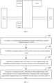
- FIG. 2 shows a flow chart of the implementation of a vehicle controlling method according to an embodiment of the present application, which will be described in detail as follows: Step 201: in response to a starting impetus-accumulation instruction, determining a required outputted torque of a vehicle.
- the starting refers to the conversion from the stationary state to the movement state of the vehicle.
- the required outputted torque of the vehicle may be determined based on a vehicle working condition, the vehicle working condition includes the accelerator-pedal depth.
- the required outputted torque and the opening degree of the accelerator pedal are of a relationship of positive correlation. In other words, if the opening degree of the accelerator pedal is higher, the corresponding required outputted torque is higher, and if the opening degree of the accelerator pedal is lower, the corresponding required outputted torque is lower.
- the required outputted torque includes a first outputted torque of the engine and a second outputted torque of the driving electric motor.
- the first outputted torque and the second outputted torque refer to, in the current state, i.e., the state that the starting impetus-accumulation instruction has been received, the outputted torque that the vehicle controller allocates for the engine and the outputted torque that the vehicle controller allocates for the driving electric motor, respectively.
- the first outputted torque may be less than or equal to the maximum torque that the engine is capable of supplying
- the second outputted torque may be less than or equal to the maximum torque that the driving electric motor is capable of supplying
- the sum of the first outputted torque and the second outputted torque is the required outputted torque.
- the step of determining the required outputted torque of the vehicle based on the vehicle working condition may include: determining the required outputted torque corresponding to an accelerator-pedal depth by using a predetermined data table.
- the predetermined data table may contain the corresponding relationship between the accelerator-pedal depth and the required outputted torque, and the predetermined data table may be obtained by pre-calibration.
- the predetermined data table may be obtained by detecting, recording and verifying a rule of the variations of the accelerator-pedal depth and the required outputted torque by simulation experimentation, to accordingly obtain the corresponding relationship between the accelerator-pedal depth and the required outputted torque.
- the predetermined data table may also be obtained by calculating and designing the corresponding relationship between the accelerator-pedal depth and the required outputted torque in advance.
- the pre-calibration may be performed in various modes, which a person skilled in the art can know and are not described in detail.
- the required outputted torque and the total available torque that the vehicle is capable of supplying may be compared. If the required outputted torque is less than or equal to the total available torque, then the impetus-accumulation for the starting of the vehicle may be performed according to the required outputted torque. If the required outputted torque is greater than the total available torque, it indicates that the torque required by the vehicle is excessively large and cannot be supplied by the vehicle, and therefore the numerical value of the required outputted torque may be reduced to the numerical value corresponding the total available torque or to be lower than the numerical value corresponding the total available torque, to perform impetus-accumulation for the starting of the vehicle.
- the total available torque may refer to the torque that the power system of the vehicle is currently capable of supplying. In other words, the total available torque may be determined based on the first available torque of the engine and the second available torque of the driving electric motor.
- the first available torque is the torque that the engine is currently capable of supplying
- the second available torque is the torque that the driving electric motor is currently capable of supplying
- the total available torque is the sum of the first available torque and the second available torque.
- the second available torque may be determined based on the discharging power and the rotational speed of the driving electric motor, and the first available torque may be a numerical value fed back by the engine.
- the second outputted torque may be less than or equal to the second available torque, and the first outputted torque may be less than or equal to the first available torque.
- the second available torque Tq motor may be compared with the maximum torque of the driving electric motor, to prevent that the second available torque Tq motor obtained by calculation is greater than the maximum torque that the driving electric motor is capable of supplying, which causes that the driving electric motor cannot supply the torque corresponding to the second available torque.
- the maximum torque of the driving electric motor may be the maximum torque that the driving electric motor is calibrated to be capable of outputting.
- the total available torque is determined according to the sum of the second available torque Tq motor and the first available torque Tq engine . If the second available torque Tq motor is greater than the maximum torque of the driving electric motor, the total available torque is determined according to the sum of the maximum torque of the driving electric motor and the first available torque Tq engine .
- the driving electric motor has a higher response, and can output the given torque more quickly than the engine, firstly the corresponding torque may be allocated to the driving electric motor according to the available torque of the driving electric motor, and subsequently the remaining torque is allocated to the engine.
- the required outputted torque T req may be firstly allocated to the driving electric motor and outputted according to the second available torque Tq motor , at this moment, the second outputted torque is equal to the second available torque Tq motor . Subsequently, the remaining torque is allocated to the engine, i.e., the torque obtained by subtracting the second available torque Tq motor from the required outputted torque T req .
- the required outputted torque T req may be firstly allocated to the driving electric motor and outputted according to a certain torque T'q motor less than the second available torque Tq motor . Subsequently, the remaining torque is allocated to the engine, i.e., the torque obtained by subtracting the torque T'q motor from the required outputted torque Treq.
- the starting impetus-accumulation instruction may be triggered based on the brake pedal and the accelerator pedal. For example, if the opening degree of the brake pedal is greater than or equal to a first opening-degree threshold, and the opening degree of the accelerator pedal is greater than or equal to a second opening-degree threshold, then the vehicle controller generates the starting impetus-accumulation instruction.
- the first opening-degree threshold may be the threshold corresponding to the maximum opening degree of the brake pedal
- the second opening-degree threshold may be the threshold corresponding to the maximum opening degree of the accelerator pedal.
- the first opening-degree threshold may be 80%
- the second opening-degree threshold may be 70%. It should be noted that the above description on the first opening-degree threshold and the second opening-degree threshold is merely exemplary, and is not a limitation, a person skilled in the art may set the first opening-degree threshold and the second opening-degree threshold of other numerical values according to demands.
- the vehicle state may include a battery SOC (State Of Charge), a battery-pack temperature, a battery-pack discharging power, a driving-electric-motor temperature, an ESP (Electronic Stability Program) state and a safety-belt state.
- SOC State Of Charge
- a battery-pack temperature a battery-pack discharging power
- a driving-electric-motor temperature a battery-pack discharging power
- ESP Electronic Stability Program
- the step of determining the required outputted torque of the vehicle based on the vehicle working condition is executed.
- the battery SOC can reflect the remaining capacity of the battery.
- the discharging of the battery pack of the driving electric motor is required to be used to supply the torque, and therefore it is required to detect in advance whether the battery SOC is greater than the SOC threshold. If the battery SOC is less than the SOC threshold, it may cause that the torque that the driving electric motor is capable of supplying decreases, the effect of starting is poor.
- the battery-pack temperature can reflect the state of the battery. If the temperature of the battery pack is excessively high or excessively low (not in the first predetermined range), that may affect the parameter performance of the battery pack, so that the performance of the battery pack is reduced. Moreover, in the starting of the vehicle, the discharging of the battery pack of the driving electric motor is required to be used to supply the torque, in this way, that may cause that the torque that the driving electric motor is capable of supplying decreases, and the effect of starting is poor.
- the first predetermined range refers to a temperature range that does not affect the parameter performance of the battery pack.
- the battery-pack discharging power can reflect the capacity of discharging of the battery pack.
- the discharging of the battery pack of the driving electric motor is required to be used to supply the torque, and if the discharging power of the battery pack is less than the power threshold, that may cause that the torque that the driving electric motor is capable of supplying decreases, and the effect of starting is poor.
- the first predetermined range refers to a temperature range that does not affect the parameter performance of the battery pack.
- the driving-electric-motor temperature can reflect the performance of the driving electric motor. If the temperature of the driving electric motor is excessively high or excessively low (not in the second predetermined range), that may affect the performance of the driving electric motor, and cause the outputted torque of the driving electric motor to decrease. Moreover, in the starting of the vehicle, the discharging of the battery pack of the driving electric motor is required to be used to supply the torque, in this way, that might cause that the torque that the driving electric motor is capable of supplying decreases, and the effect of starting is poor.
- the second predetermined range refers to a temperature range that does not affect the performance of the driving electric motor.
- the ESP state because in the starting of the vehicle, a large torque is used, slipping of the vehicle wheels might happen. If the ESP state is started-up, the ESP system may intervene to reduce the torque to maintain the stability of the vehicle body, which also causes that the power in the starting of the vehicle decreases, and the effect of starting is poor.
- the safety-belt state can characterize whether the driver and the on-board passengers have already fastened tightly the safety belt. If the safety-belt state is that the safety belts have been fastened tightly, then launch control may be performed. If the safety belts have not been fastened tightly, then the users may be prompted to fasten tightly the safety belts and subsequently launch control is performed, or launch control is not performed (for example, the execution of the subsequent steps may be stopped).
- Step 202 controlling an outputted torque of a driving electric motor to be a second outputted torque.
- the driving electric motor may be allocated the corresponding torque according to the maximum torque of the driving electric motor, and subsequently the remaining torque is allocated to the engine.
- the required outputted torque T req may be firstly allocated to the driving electric motor and outputted according to the second available torque Tq motor . Subsequently, the remaining torque is allocated to the engine, i.e., the torque obtained by subtracting the second available torque Tq motor from the required outputted torque T req .
- the required outputted torque T req may be firstly allocated to the driving electric motor and outputted according to a certain torque T'q motor less than the second available torque Tq motor . Subsequently, the remaining torque is allocated to the engine, i.e., the torque obtained by subtracting the torque T'q motor from the required outputted torque Treq.
- Step 203 controlling an outputted torque of an engine to be a first outputted torque, and controlling an outputted torque of an electric generator to be a third outputted torque.
- the electric generator and the engine are connected by using a planetary gear, and the third outputted torque and the first outputted torque are balance with each other, so that the outputted torque at the crankshaft end of the engine is zero. Furthermore, the sum of the second outputted torque and the first outputted torque is the required outputted torque.
- the electric generator is further controlled to output the third outputted torque, so that the third outputted torque and the first outputted torque are balance with each other, to achieve the object that the outputted torque of the crankshaft end of the engine is zero.
- the implementation process of the step 203 may include: controlling a rotational speed of the engine to be a preset rotational speed; sending a torque intervening instruction to the engine and the electric generator, and controlling a state of a clutch to be a slipping state; and in response to the torque intervening instruction, synchronously increasing the outputted torque of the engine and the outputted torque of the electric generator, so that the outputted torque of the engine reaches the first outputted torque, and the outputted torque of the electric generator reaches the third outputted torque.
- the vehicle before the launch control, the vehicle is required to output the torque in the stationary state, thus the effect of launch control can be reached.
- the driving electric motor can directly respond to the torque, and the crankshaft end of the engine, when the vehicle is stationary, cannot close the clutch if the engine responds to the torque.
- the HCU Hybrid Control Unit
- the HCU Hybrid Control Unit
- the direct driving mode is entered, the outputted torque of the engine is requested to be T req - Tq motor , and the outputted torque of the electric generator is requested to be 0- speed ratio*(T req -Tq motor ). Subsequently, synchronous increasing of the outputted torque of the engine and the outputted torque of the electric generator is started, thus it is ensured that, when the clutch is engaged, the outputted torque of the crankshaft end of the engine is 0.
- the speed ratio is determined based on the gear train between the engine and the electric generator, which is well known by a person skilled in the art and is not described in detail.
- Step 204 in response to a starting instruction, controlling the third outputted torque of the electric generator to exit in a predetermined mode, and based on the second outputted torque and the outputted torque of the crankshaft end of the engine, driving the vehicle to start.
- the starting instruction may be triggered when the opening degree of the brake pedal is zero; in other words, when it is detected that the opening degree of the brake pedal is less than a third opening-degree threshold, the third outputted torque of the electric generator is controlled to exit in a gradient decreasing method.
- the outputted torque of the crankshaft end of the engine gradually increases within a short duration, and the power system of the vehicle, via the second outputted torque outputted by the driving electric motor and the outputted torque of the crankshaft end of the engine, drives the vehicle to realize the launch control.
- the required outputted torque of the vehicle may be determined based on the accelerator-pedal depth and the vehicle travelling speed jointly.
- the corresponding required outputted torque may be determined by using a predetermined data table according to the accelerator-pedal depth and the vehicle travelling speed.
- the predetermined data table may contain the corresponding relationship among the accelerator-pedal depth, the vehicle travelling speed and the required outputted torque.
- the predetermined data table may be obtained by pre-calibration, wherein the mode of the pre-calibration is similar to the mode of the above-described pre-calibration, and is not discussed further herein.
- the torque impetus-accumulation before the starting of the vehicle, in response to the starting impetus-accumulation instruction, the torque impetus-accumulation is performed, the outputted torque of the driving electric motor is controlled to be the second outputted torque, and the outputted torque of the engine is controlled to be the first outputted torque, the torque impetus-accumulation is performed by using the driving electric motor and the engine to increase the starting power.
- the electric generator is controlled to output the third outputted torque, so that the third outputted torque and the first outputted torque are balance with each other, to achieve the object that the outputted torque of the crankshaft end of the engine is zero.
- the third outputted torque of the electric generator is controlled to exit in the predetermined mode, so that based on the joint effect of the second outputted torque and the outputted torque of the crankshaft end of the engine, the vehicle can be driven to start with a large torque.
- FIG. 3 shows a schematic structural diagram of a vehicle controlling apparatus according to an embodiment of the present application.
- FIG. 3 shows a schematic structural diagram of a vehicle controlling apparatus according to an embodiment of the present application.
- the parts relevant to the embodiments of the present application are shown, and they will be described in detail as follows:
- the vehicle controlling apparatus 300 may include a required-outputted-torque determining module 301, a first-torque controlling module 302, a second-torque controlling module 303 and a starting controlling module 304.
- the required-outputted-torque determining module 301 is configured for in response to a starting impetus-accumulation instruction, determining a required outputted torque of a vehicle.
- the first-torque controlling module 302 is configured for controlling an outputted torque of a driving electric motor to be a second outputted torque.
- the second-torque controlling module 303 is configured for controlling an outputted torque of an engine to be a first outputted torque, and controlling an outputted torque of an electric generator to be a third outputted torque, wherein the third outputted torque and the first outputted torque are balance with each other, so that an outputted torque at a crankshaft end of the engine is zero, and a sum of the second outputted torque and the first outputted torque is the required outputted torque.
- the starting controlling module 304 is configured for in response to a starting instruction, controlling the third outputted torque of the electric generator to exit in a predetermined mode, and based on the second outputted torque and the outputted torque of the crankshaft end of the engine, driving the vehicle to start.
- the vehicle controlling apparatus 300 may further include: a detecting module configured for detecting whether a vehicle state satisfies a predetermined condition, the vehicle state includes a battery SOC, a battery-pack temperature, a battery-pack discharging power, a driving-electric-motor temperature, an ESP state and a safety-belt state.
- a detecting module configured for detecting whether a vehicle state satisfies a predetermined condition, the vehicle state includes a battery SOC, a battery-pack temperature, a battery-pack discharging power, a driving-electric-motor temperature, an ESP state and a safety-belt state.
- the required-outputted-torque determining module 301 executes the operation of determining the required outputted torque of the vehicle based on the vehicle working condition.
- the second-torque controlling module 303 may be specifically configured for: controlling a rotational speed of the engine to be a preset rotational speed; sending a torque intervening instruction to the engine and the electric generator, and controlling a state of a clutch to be a slipping state, the engine is connected to a vehicle wheel via the clutch; and in response to the torque intervening instruction, synchronously increasing the outputted torque of the engine and the outputted torque of the electric generator, so that the outputted torque of the engine reaches the first outputted torque, and the outputted torque of the electric generator reaches the third outputted torque.
- the starting controlling module 304 may be specifically configured for, when it is detected that an opening degree of a brake pedal is less than a third opening-degree threshold, controlling the third outputted torque of the electric generator to exit in a gradient decreasing method.
- the vehicle controlling apparatus 300 may further include: a total-available-torque calculating module configured for calculating a total available torque of the vehicle, the total available torque is determined based on a first available torque of the engine and a second available torque of the driving electric motor, and the second available torque is determined based on a discharging power and a rotational speed of the driving electric motor, wherein the second outputted torque is less than or equal to the second available torque, and the first outputted torque is less than or equal to the first available torque.
- a total-available-torque calculating module configured for calculating a total available torque of the vehicle, the total available torque is determined based on a first available torque of the engine and a second available torque of the driving electric motor, and the second available torque is determined based on a discharging power and a rotational speed of the driving electric motor, wherein the second outputted torque is less than or equal to the second available torque, and the first outputted torque is less than or equal to the first available torque.
- the first outputted torque is determined based on a difference between the required outputted torque and the second outputted torque; and if the total available torque is less than the required outputted torque, the first outputted torque is determined based on a difference between the total available torque and the second outputted torque.
- the required-outputted-torque determining module 301 may be specifically configured for: determining the required outputted torque corresponding to an accelerator-pedal depth by using a predetermined data table, wherein the predetermined data table contains a corresponding relationship between the accelerator-pedal depth and the required outputted torque.
- An embodiment of the present application provides a vehicle including an electronic device, the electronic device includes a memory, a processor, and a computer program that is stored in the memory and executable in the processor, the processor, when executing the computer program, implements the steps of any one of the above embodiments of the vehicle controlling method, for example, the step 201 to the step 204 shown in FIG. 2 .
- An embodiment of the present application further provides a computer program product, the computer program product has a program code, and the program code, when executed in a corresponding processor, controller, computing device or terminal, implements the steps of any one of the above embodiments of the vehicle controlling method, for example, the step 201 to the step 204 shown in FIG. 2 .
- the dedicated processors may include an application specific integrated circuit (ASIC), a reduced instruction-set computer (RISC) and/or a field-programmable gate array (FPGA).
- ASIC application specific integrated circuit
- RISC reduced instruction-set computer
- FPGA field-programmable gate array
- the proposed method and device are preferably implemented as a combination of hardware and software.
- the software is preferably installed in a program storage device as an application program. It is typically a machine based on a computer platform having hardware, for example, one or more central processing units (CPU), a random access memory (RAM) and one or more inputting/outputting (I/O) interfaces.
- the operating system is typically also installed in the computer platform.
- the processes and the functions described herein may be a part of the application program, or a part of the application program may be performed by the operating system.
- FIG. 4 is a schematic diagram of an electronic device according to an embodiment of the present application.
- the electronic device 400 includes a processor 401, a memory 402, and a computer program 403 that is stored in the memory 402 and executable in the processor 401.
- the processor 401 when executing the computer program 403, implements the steps of the above embodiments of the vehicle controlling method, for example, the step 201 to the step 204 shown in FIG. 2 .
- the processor 401 when executing the computer program 403, implements the functions of the modules according to the above apparatus embodiments, for example, the functions of the module 301 to thee module 304 shown in FIG. 3 .
- the computer program 403 may be divided into one or more modules, and the one or more modules are stored in the memory 402, and are executed by the processor 401, to complete/implement the solutions according to the present application.
- the one or more modules may be a series of computer program instruction segments that can complete specific functions, and the instruction segments are used to describe the process of the execution of the computer program 403 in the electronic device 400.
- the computer program 403 may be divided into the module 301 to the module 304 shown in FIG. 3 .
- the electronic device 400 may be a computing device such as a vehicle controller, a mobile phone, a notebook computer, a palmtop and a cloud server.
- the electronic device 400 may include, without limitation, a processor 401 and a memory 402.
- FIG. 4 is merely an example of the electronic device 400, and does not limit the electronic device 400, and the electronic device 400 may include more or fewer components than those shown in the figure, or a combination of some of the components, or different components.
- the electronic device 400 may further include an inputting-outputting device, a network accessing device, a bus and so on.
- the processors 401 may be a central processing unit (CPU), and may also be another generic processor, digital signal processor (DSP), application specific integrated circuit (ASIC), field-programmable gate array (FPGA) or another programmable logic device, discrete gate or transistor logic device, discrete hardware assembly and so on.
- the generic processor may be a microprocessor, and the processor may also be any conventional processor.
- the memory 402 may be an internal storage unit of the electronic device 400, for example, a hard disk or an internal memory of the electronic device 400.
- the memory 402 may also be an external storage device of the electronic device 400, for example, a plug-connected hard disk, a smart media card (SMC), a secure digital (SD) card, a flash card, and so on, that the electronic device 400 is equipped with. Further, the memory 402 may also include not only the internal storage unit of the electronic device 400 but also the external storage device.
- the memory 402 is configured to store the computer program, and other programs and data that are required by the electronic device.
- the memory 402 may also be configured to temporarily store the data that have already been outputted or will be outputted.
- the division of the above functional units and modules is merely taken as an example for the description.
- the above functions may be allocated to be completed by different functional units and modules according to demands, i.e., dividing the internal structure of the apparatus into different functional units or modules, to complete all or some of the functions described above.
- the functional units and modules according to the embodiments may be integrated into one processing unit, or the units may also separately physically exist, or two or more of the units may also be integrated into one unit.
- the above-described integrated unit may be implemented in the form of hardware, and may also be implemented in the form of a software function unit.
- the disclosed apparatus/terminal and method may be implemented in other manners.
- the above-described device/terminal embodiments are merely illustrative.
- the division between the modules/units is merely a division in the logic functions, and in the practical implementation there may be another mode of division.
- multiple units or components may be combined or may be integrated into another system, or some of the features may be omitted, or not implemented.
- the coupling or direct coupling or communicative connection between the illustrated or discussed components may be via interfaces or the indirect coupling or communicative connection between the devices or units, and may be electric, mechanical or in other forms.
- the units that are described as separate components may or may not be physically separate, and the components that are displayed as units may or may not be physical units; in other words, they may be located at the same location, and may also be distributed into a plurality of network units. Some or all of the units may be selected according to practical demands to realize the objects of the solutions of the embodiments.
- the functional units according to the embodiments of the present application may be integrated into one processing unit, or the units may also separately physically exist, or two or more of the units may also be integrated into one unit.
- the above-described integrated unit may be implemented in the form of hardware, and may also be implemented in the form of a software function unit.
- the integrated modules/units if implemented in the form of software function units and sold or used as an independent product, may be stored in a computer-readable storage medium.
- all or some of the processes of the methods according to the embodiments of the present application may be implemented by relative hardware according to an instruction from a computer program, the computer program may be stored in a non-transitory computer-readable storage medium, and the computer program, when executed by a processor, can implement the steps of the above embodiments of the vehicle controlling method.
- the computer program includes a computer program code, and the computer program code may be a source code, an object code, an executable file, some intermediate forms, and so on.
- the computer-readable storage medium may include any entity or device that can carry the computer program code, including a recording medium, a USB flash disk, a mobile hard disk drive, a diskette, an optical disk, a computer memory, a read-only memory (ROM), a random access memory (RAM), an electric carrier signal, a telecommunication signal, a software distribution medium and so on.
- a recording medium including a USB flash disk, a mobile hard disk drive, a diskette, an optical disk, a computer memory, a read-only memory (ROM), a random access memory (RAM), an electric carrier signal, a telecommunication signal, a software distribution medium and so on.
- ROM read-only memory
- RAM random access memory
- an electric carrier signal a telecommunication signal
- software distribution medium and so on.
Landscapes
- Engineering & Computer Science (AREA)
- Transportation (AREA)
- Mechanical Engineering (AREA)
- Chemical & Material Sciences (AREA)
- Combustion & Propulsion (AREA)
- Automation & Control Theory (AREA)
- Power Engineering (AREA)
- Life Sciences & Earth Sciences (AREA)
- Sustainable Development (AREA)
- Sustainable Energy (AREA)
- Hybrid Electric Vehicles (AREA)
- Electric Propulsion And Braking For Vehicles (AREA)
Abstract
Description
- The present patent application claims the priority of the Chinese patent application filed on
January 7th, 2022 with the application number of No. CN 202210017707.8 - The present application relates to the technical field of vehicles and, more particularly, to a vehicle controlling method and apparatus, and a vehicle.
- In existing vehicles, the brake pedal and the accelerator pedal are used as the core component parts for identifying the driving intention of the driver. By stepping on the brake pedal with a single foot, the braking of the vehicle can be realized. By stepping on the accelerator pedal with a single foot, the starting is realized. Usually, while the brake pedal is being stepped on and after the brake pedal has been completely stepped on down, the torque outputting of the engine is stopped. Merely in the process that the brake pedal is being slowly released, a torque of the engine may be started to be slowly loaded. After the brake pedal is completely released, the vehicle starts to enter a creep mode, and starts to travel slowly. After the accelerator is stepped on, the vehicle identifies the intention of acceleration of the driver, and starts to travel according to the intention of the driver.
- In the starting of the vehicle, the brake pedal and the accelerator pedal may be operated at a same time to realize highly increasing the starting power before the starting of the vehicle, so that the vehicle can be quickly started with a greater power, i.e., realizing a function of launch control (ejection mode). Usually, the accelerator pedal is also referred to as the accelerator pedal. The conventional launch control is realized mostly by controlling the engine by using the accelerator pedal to output a large torque. However, the torque outputted by the engine has an upper limit, and, therefore, if the launch control of the vehicle is to be realized merely by relying on the torque outputted by the engine, the effect is poor.
- A vehicle controlling method and apparatus, and a vehicle are provided by the present application, the vehicle can be driven to start by using the torque of the engine and the torque of the driving electric motor jointly, quick starting of the vehicle with a large torque is realized, and the problem that the upper limit of the torque outputted by the engine causes a poor effect of launch control of the vehicle is solved.
- In the first aspect, a vehicle controlling method is provided by the present application, the method includes: in response to a starting impetus-accumulation instruction, determining a required outputted torque of a vehicle; controlling an outputted torque of a driving electric motor to be a second outputted torque; controlling an outputted torque of an engine to be a first outputted torque, and controlling an outputted torque of an electric generator to be a third outputted torque, wherein the third outputted torque and the first outputted torque are balance with each other, so that an outputted torque at a crankshaft end of the engine is zero, and a sum of the second outputted torque and the first outputted torque is the required outputted torque; and
in response to a starting instruction, controlling the third outputted torque of the electric generator to exit in a predetermined mode, and based on the second outputted torque and the outputted torque of the crankshaft end of the engine, driving the vehicle to start. - In a possible implementation, after the step of in response to the starting impetus-accumulation instruction, the method further includes: detecting whether a vehicle state satisfies a predetermined condition, wherein the vehicle state includes a battery SOC (state of charge), a battery-pack temperature, a battery-pack discharging power, a driving-electric-motor temperature, an electronic stability program (ESP) state and a safety-belt state; and when the battery SOC is greater than an SOC threshold, the battery-pack temperature is in a first predetermined range, the battery-pack discharging power is greater than a power threshold, the driving-electric-motor temperature is in a second predetermined range, the ESP state is off and the safety-belt state is fastened-tightly, executing the step of determining the required outputted torque of the vehicle.
- In a possible implementation, the step of controlling the outputted torque of the engine to be the first outputted torque, and controlling the outputted torque of the electric generator to be the third outputted torque includes: controlling a rotational speed of the engine to be a preset rotational speed; sending a torque intervening instruction to the engine and the electric generator, and controlling a state of a clutch to be a slipping state, wherein the engine is connected to a vehicle wheel via the clutch; and in response to the torque intervening instruction, synchronously increasing the outputted torque of the engine and the outputted torque of the electric generator, so that the outputted torque of the engine reaches the first outputted torque, and the outputted torque of the electric generator reaches the third outputted torque.
- In a possible implementation, the step of in response to the starting instruction, controlling the third outputted torque of the electric generator to exit in the predetermined mode includes:
when it is detected that an opening degree of a brake pedal is less than a opening-degree threshold, controlling the third outputted torque of the electric generator to exit in a gradient decreasing mode. - In a possible implementation, the method further includes: calculating a total available torque of the vehicle, wherein the total available torque is determined based on a first available torque of the engine and a second available torque of the driving electric motor, and the second available torque is determined based on a discharging power and a rotational speed of the driving electric motor; wherein when the total available torque is greater than or equal to the required outputted torque, determining the first outputted torque based on a difference between the required outputted torque and the second outputted torque; and when the total available torque is less than the required outputted torque, determining the first outputted torque based on a difference between the total available torque and the second outputted torque.
- In a possible implementation, the second outputted torque is less than or equal to the second available torque, and the first outputted torque is less than or equal to the first available torque.
- In a possible implementation, the step of determining the required outputted torque of the vehicle includes: determining the required outputted torque corresponding to an accelerator-pedal depth by using a predetermined data table, wherein the predetermined data table contains a corresponding relationship between the accelerator-pedal depth and the required outputted torque.
- In the second aspect, a vehicle controlling apparatus is provided by the present application, which includes: a required-outputted-torque determining module configured for in response to a starting impetus-accumulation instruction, determining a required outputted torque of a vehicle; a first-torque controlling module configured for controlling an outputted torque of a driving electric motor to be a second outputted torque; a second-torque controlling module configured for controlling an outputted torque of an engine to be a first outputted torque, and controlling an outputted torque of an electric generator to be a third outputted torque, wherein the third outputted torque and the first outputted torque are balance with each other, so that an outputted torque at a crankshaft end of the engine is zero, and a sum of the second outputted torque and the first outputted torque is the required outputted torque; and a starting controlling module configured for in response to a starting instruction, controlling the third outputted torque of the electric generator to exit in a predetermined mode, and based on the second outputted torque and the outputted torque of the crankshaft end of the engine, driving the vehicle to start.
- In the third aspect, the present application provides an electronic device including a memory, a processor and a computer program that is stored in the memory and executable in the processor, the processor, when executing the computer program, implements the steps of the method according to the first aspect or any one of the possible implementations of the first aspect.
- In the fourth aspect, the present application provides a vehicle, including an electronic device, the electronic device includes a memory, a processor and a computer program that is stored in the memory and executable in the processor, wherein the processor, when executing the computer program, implements the steps of the method according to the first aspect or any one of the possible implementations of the first aspect.
- In the fifth aspect, the present application provides a non-transitory computer-readable storage medium, the computer-readable storage medium storing a computer program, the computer program, when executed by a processor, implements the steps of the method according to the first aspect or any one of the possible implementations of the first aspect.
- In the sixth aspect, the present application provides a computer program product, wherein the computer program product has a program code, and the program code, when executed in a corresponding processor, controller, computing device or electronic device, implements the steps of the method according to the first aspect or any one of the possible implementations of the first aspect.
- In the vehicle controlling method and apparatus, and the vehicle according to the present application, before the starting of the vehicle, in response to the starting impetus-accumulation instruction, torque impetus-accumulation is performed, the outputted torque of the driving electric motor is controlled to be the second outputted torque, and the outputted torque of the engine is controlled to be the first outputted torque, by using the driving electric motor and the engine simultaneously to perform torque impetus-accumulation, the starting power is increased. Because before the starting, the crankshaft end of the engine cannot apply the torque to the vehicle wheels, or else that results in travelling of the vehicle or flameout of the engine, in the present application, simultaneously when the outputted torque of the engine is adjusted to be the first outputted torque, the electric generator is further controlled to output the third outputted torque, so that the third outputted torque and the first outputted torque are balance with each other, to achieve the goal that the outputted torque of the crankshaft end of the engine is zero. Subsequently, after the starting instruction is received, the third outputted torque of the electric generator is controlled to exit in the predetermined mode, so that based on the joint effect of the second outputted torque and the outputted torque of the crankshaft end of the engine, the vehicle can be driven to start with a large torque.
- In order to more clearly illustrate the technical solutions of the embodiments of the present application, the figures that are required to be used to describe the embodiments or the related art will be briefly described below. Apparently, the figures that are described below are some embodiments of the present application, and a person skilled in the art can obtain other figures according to these figures without paying creative work.
-
FIG. 1 is a schematic diagram of a vehicle power system according to an embodiment of the present application; -
FIG. 2 is a schematic flow chart of a vehicle controlling method according to an embodiment of the present application; -
FIG. 3 is a schematic structural diagram of a vehicle controlling apparatus according to an embodiment of the present application; and -
FIG. 4 is a schematic diagram of an electronic device according to an embodiment of the present application. - In the following description, in order for description rather than limitation, particular details such as particular system structures and techniques are provided, to facilitate to thoroughly comprehend the embodiments of the present application. However, a person skilled in the art should clearly know that the present application may also be implemented in the embodiments that do not have those particular details. In other cases, the detailed description on the well-known systems, devices, circuits and methods is omitted, to prevent affecting the description on the present application by unnecessary details.
- In order to make the objects, the technical solutions and the advantages of the present application clearer, the present application will be described below with reference to the drawings and the particular embodiments.
- In order to facilitate to comprehend the solutions of the embodiments of the present application, firstly the vehicle power system related to the embodiments of the present application will be described briefly below. Referring to
FIG. 1 , the vehicle power system may include an engine, an electric generator and a driving electric motor. The driving electric motor is connected to the vehicle wheels, the engine is connected to the electric generator via a gear train, and the output-shaft end of the engine is connected to the vehicle wheels via a clutch. When the clutch is in the engaging state, the engine and the driving electric motor drive the vehicle wheels together. When the clutch is in the disengaging state, the driving electric motor drives the vehicle wheels. - In the starting of the vehicle, in order to enable the vehicle to start with a large power, the vehicle may be driven to start with a large torque by the joint effect of the outputted torque of the driving electric motor and the outputted torque of the engine. However, before the starting, the crankshaft end of the engine cannot apply the torque to the vehicle wheels, or else that results in flameout of the engine of the vehicle. At this moment, the outputted torque of the electric generator may be adjusted simultaneously when the outputted torque of the engine is adjusted, so that the outputted torque of the engine and the outputted torque of the electric generator are balance with each other, to achieve the goal that the outputted torque of the crankshaft end of the engine is zero.
- Specifically, a rotational speed of the engine may be controlled to be a preset rotational speed, and a state of the clutch is controlled to be a slipping state; subsequently, the outputted torque of the engine and the outputted torque of the electric generator are synchronously increased, so that the outputted torque of the engine and the outputted torque of the electric generator reach the effect of real-time dynamic balance; and when a starting instruction (an opening degree of the brake pedal is less than an opening-degree threshold) is detected, the outputted torque of the electric generator is controlled to exit in a gradient decreasing method, and subsequently the vehicle is driven to start by using the outputted torque of the driving electric motor and the outputted torque of the engine.
- The vehicle controlling method according to the embodiments of the present application will be described in detail below with reference to
FIG. 1 . - Referring to
FIG. 2, FIG. 2 shows a flow chart of the implementation of a vehicle controlling method according to an embodiment of the present application, which will be described in detail as follows:
Step 201: in response to a starting impetus-accumulation instruction, determining a required outputted torque of a vehicle. - As an example, the starting refers to the conversion from the stationary state to the movement state of the vehicle. The required outputted torque of the vehicle may be determined based on a vehicle working condition, the vehicle working condition includes the accelerator-pedal depth. The required outputted torque and the opening degree of the accelerator pedal are of a relationship of positive correlation. In other words, if the opening degree of the accelerator pedal is higher, the corresponding required outputted torque is higher, and if the opening degree of the accelerator pedal is lower, the corresponding required outputted torque is lower.
- The required outputted torque includes a first outputted torque of the engine and a second outputted torque of the driving electric motor. The first outputted torque and the second outputted torque refer to, in the current state, i.e., the state that the starting impetus-accumulation instruction has been received, the outputted torque that the vehicle controller allocates for the engine and the outputted torque that the vehicle controller allocates for the driving electric motor, respectively. The first outputted torque may be less than or equal to the maximum torque that the engine is capable of supplying, the second outputted torque may be less than or equal to the maximum torque that the driving electric motor is capable of supplying, and the sum of the first outputted torque and the second outputted torque is the required outputted torque.
- As an example, the step of determining the required outputted torque of the vehicle based on the vehicle working condition may include: determining the required outputted torque corresponding to an accelerator-pedal depth by using a predetermined data table. The predetermined data table may contain the corresponding relationship between the accelerator-pedal depth and the required outputted torque, and the predetermined data table may be obtained by pre-calibration. For example, the predetermined data table may be obtained by detecting, recording and verifying a rule of the variations of the accelerator-pedal depth and the required outputted torque by simulation experimentation, to accordingly obtain the corresponding relationship between the accelerator-pedal depth and the required outputted torque. Alternatively, the predetermined data table may also be obtained by calculating and designing the corresponding relationship between the accelerator-pedal depth and the required outputted torque in advance. In the present embodiment, the pre-calibration may be performed in various modes, which a person skilled in the art can know and are not described in detail.
- After the required outputted torque has been obtained, the required outputted torque and the total available torque that the vehicle is capable of supplying may be compared. If the required outputted torque is less than or equal to the total available torque, then the impetus-accumulation for the starting of the vehicle may be performed according to the required outputted torque. If the required outputted torque is greater than the total available torque, it indicates that the torque required by the vehicle is excessively large and cannot be supplied by the vehicle, and therefore the numerical value of the required outputted torque may be reduced to the numerical value corresponding the total available torque or to be lower than the numerical value corresponding the total available torque, to perform impetus-accumulation for the starting of the vehicle.
- In some embodiments, the total available torque may refer to the torque that the power system of the vehicle is currently capable of supplying. In other words, the total available torque may be determined based on the first available torque of the engine and the second available torque of the driving electric motor.
- Specifically, the first available torque is the torque that the engine is currently capable of supplying, the second available torque is the torque that the driving electric motor is currently capable of supplying, and the total available torque is the sum of the first available torque and the second available torque. Moreover, the second available torque may be determined based on the discharging power and the rotational speed of the driving electric motor, and the first available torque may be a numerical value fed back by the engine. The second outputted torque may be less than or equal to the second available torque, and the first outputted torque may be less than or equal to the first available torque.
- For example, the total available torque may be the sum of the first available torque Tq engine and the second available torque Tq motor , and the second available torque may be obtained by calculation according to the formula Tq motor =a • P/n, a is a predetermined coefficient, P is a discharging power of the driving electric motor, and n is the rotational speed of the driving electric motor, a may be 9550.
- In addition, after the second available torque Tq motor has been obtained by calculation according to the formula Tq motor =a • P/n, the second available torque Tq motor may be compared with the maximum torque of the driving electric motor, to prevent that the second available torque Tq motor obtained by calculation is greater than the maximum torque that the driving electric motor is capable of supplying, which causes that the driving electric motor cannot supply the torque corresponding to the second available torque. The maximum torque of the driving electric motor may be the maximum torque that the driving electric motor is calibrated to be capable of outputting.
- If the second available torque Tq motor is less than or equal to the maximum torque of the driving electric motor, the total available torque is determined according to the sum of the second available torque Tq motor and the first available torque Tq engine. If the second available torque Tq motor is greater than the maximum torque of the driving electric motor, the total available torque is determined according to the sum of the maximum torque of the driving electric motor and the first available torque Tq engine.
- Because the driving electric motor has a higher response, and can output the given torque more quickly than the engine, firstly the corresponding torque may be allocated to the driving electric motor according to the available torque of the driving electric motor, and subsequently the remaining torque is allocated to the engine.
- For example, the required outputted torque T req may be firstly allocated to the driving electric motor and outputted according to the second available torque Tq motor , at this moment, the second outputted torque is equal to the second available torque Tq motor. Subsequently, the remaining torque is allocated to the engine, i.e., the torque obtained by subtracting the second available torque Tq motor from the required outputted torque T req .
- As another example, the required outputted torque T req may be firstly allocated to the driving electric motor and outputted according to a certain torque T'q motor less than the second available torque Tq motor . Subsequently, the remaining torque is allocated to the engine, i.e., the torque obtained by subtracting the torque T'q motor from the required outputted torque Treq.
- In a scene, the starting impetus-accumulation instruction may be triggered based on the brake pedal and the accelerator pedal. For example, if the opening degree of the brake pedal is greater than or equal to a first opening-degree threshold, and the opening degree of the accelerator pedal is greater than or equal to a second opening-degree threshold, then the vehicle controller generates the starting impetus-accumulation instruction.
- As an example, the first opening-degree threshold may be the threshold corresponding to the maximum opening degree of the brake pedal, and the second opening-degree threshold may be the threshold corresponding to the maximum opening degree of the accelerator pedal. Alternatively, the first opening-degree threshold may be 80%, and the second opening-degree threshold may be 70%. It should be noted that the above description on the first opening-degree threshold and the second opening-degree threshold is merely exemplary, and is not a limitation, a person skilled in the art may set the first opening-degree threshold and the second opening-degree threshold of other numerical values according to demands.
- In some embodiments, after in response to the starting impetus-accumulation instruction, it may be firstly detected whether the vehicle state satisfies a predetermined condition. The predetermined condition includes the information used to characterize that the driving electric motor is capable of supplying a sufficiently large torque for the starting of the vehicle, that the ESP system is not started up, that the safety belt is fastened tightly, and so on. Specifically, the vehicle state may include a battery SOC (State Of Charge), a battery-pack temperature, a battery-pack discharging power, a driving-electric-motor temperature, an ESP (Electronic Stability Program) state and a safety-belt state.
- If the battery SOC is greater than an SOC threshold, the battery-pack temperature is in a first predetermined range, the battery-pack discharging power is greater than a power threshold, the driving-electric-motor temperature is in a second predetermined range, the ESP state is off and the safety-belt state is fastened-tightly, then the step of determining the required outputted torque of the vehicle based on the vehicle working condition is executed.
- The battery SOC can reflect the remaining capacity of the battery. In the starting of the vehicle, the discharging of the battery pack of the driving electric motor is required to be used to supply the torque, and therefore it is required to detect in advance whether the battery SOC is greater than the SOC threshold. If the battery SOC is less than the SOC threshold, it may cause that the torque that the driving electric motor is capable of supplying decreases, the effect of starting is poor.
- The battery-pack temperature can reflect the state of the battery. If the temperature of the battery pack is excessively high or excessively low (not in the first predetermined range), that may affect the parameter performance of the battery pack, so that the performance of the battery pack is reduced. Moreover, in the starting of the vehicle, the discharging of the battery pack of the driving electric motor is required to be used to supply the torque, in this way, that may cause that the torque that the driving electric motor is capable of supplying decreases, and the effect of starting is poor. The first predetermined range refers to a temperature range that does not affect the parameter performance of the battery pack.
- The battery-pack discharging power can reflect the capacity of discharging of the battery pack. In the starting of the vehicle, the discharging of the battery pack of the driving electric motor is required to be used to supply the torque, and if the discharging power of the battery pack is less than the power threshold, that may cause that the torque that the driving electric motor is capable of supplying decreases, and the effect of starting is poor. The first predetermined range refers to a temperature range that does not affect the parameter performance of the battery pack.
- The driving-electric-motor temperature can reflect the performance of the driving electric motor. If the temperature of the driving electric motor is excessively high or excessively low (not in the second predetermined range), that may affect the performance of the driving electric motor, and cause the outputted torque of the driving electric motor to decrease. Moreover, in the starting of the vehicle, the discharging of the battery pack of the driving electric motor is required to be used to supply the torque, in this way, that might cause that the torque that the driving electric motor is capable of supplying decreases, and the effect of starting is poor. The second predetermined range refers to a temperature range that does not affect the performance of the driving electric motor.
- Regarding the ESP state, because in the starting of the vehicle, a large torque is used, slipping of the vehicle wheels might happen. If the ESP state is started-up, the ESP system may intervene to reduce the torque to maintain the stability of the vehicle body, which also causes that the power in the starting of the vehicle decreases, and the effect of starting is poor.
- The safety-belt state can characterize whether the driver and the on-board passengers have already fastened tightly the safety belt. If the safety-belt state is that the safety belts have been fastened tightly, then launch control may be performed. If the safety belts have not been fastened tightly, then the users may be prompted to fasten tightly the safety belts and subsequently launch control is performed, or launch control is not performed (for example, the execution of the subsequent steps may be stopped).
- Step 202: controlling an outputted torque of a driving electric motor to be a second outputted torque.
- After the required outputted torque of the vehicle is determined, because the driving electric motor has a higher response, and can output the given torque more quickly than the engine, firstly the driving electric motor may be allocated the corresponding torque according to the maximum torque of the driving electric motor, and subsequently the remaining torque is allocated to the engine.
- For example, the required outputted torque T req may be firstly allocated to the driving electric motor and outputted according to the second available torque Tq motor. Subsequently, the remaining torque is allocated to the engine, i.e., the torque obtained by subtracting the second available torque Tq motor from the required outputted torque T req .
- As another example, the required outputted torque T req may be firstly allocated to the driving electric motor and outputted according to a certain torque T'q motor less than the second available torque Tq motor . Subsequently, the remaining torque is allocated to the engine, i.e., the torque obtained by subtracting the torque T'q motor from the required outputted torque Treq.
- Step 203: controlling an outputted torque of an engine to be a first outputted torque, and controlling an outputted torque of an electric generator to be a third outputted torque.
- The electric generator and the engine are connected by using a planetary gear, and the third outputted torque and the first outputted torque are balance with each other, so that the outputted torque at the crankshaft end of the engine is zero. Furthermore, the sum of the second outputted torque and the first outputted torque is the required outputted torque.
- Because, before the starting, the crankshaft end of the engine cannot apply the torque to the vehicle wheels, or else that results in travelling of the vehicle or flameout of the engine, in the present application, simultaneously when the outputted torque of the engine is adjusted to be the first outputted torque, the electric generator is further controlled to output the third outputted torque, so that the third outputted torque and the first outputted torque are balance with each other, to achieve the object that the outputted torque of the crankshaft end of the engine is zero.
- In some embodiments, the implementation process of the
step 203 may include: controlling a rotational speed of the engine to be a preset rotational speed; sending a torque intervening instruction to the engine and the electric generator, and controlling a state of a clutch to be a slipping state; and in response to the torque intervening instruction, synchronously increasing the outputted torque of the engine and the outputted torque of the electric generator, so that the outputted torque of the engine reaches the first outputted torque, and the outputted torque of the electric generator reaches the third outputted torque. - Specifically, before the launch control, the vehicle is required to output the torque in the stationary state, thus the effect of launch control can be reached. The driving electric motor can directly respond to the torque, and the crankshaft end of the engine, when the vehicle is stationary, cannot close the clutch if the engine responds to the torque. At this moment, the HCU (Hybrid Control Unit) can control the rotational speed of the engine to be approximately 1350rpm, subsequently send the torque intervening instruction to control the outputted torque of the crankshaft end of the engine to be 0, and simultaneously control the clutch to be in the slipping state. At this moment, the direct driving mode is entered, the outputted torque of the engine is requested to be T req-Tq motor , and the outputted torque of the electric generator is requested to be 0- speed ratio*(T req -Tq motor ). Subsequently, synchronous increasing of the outputted torque of the engine and the outputted torque of the electric generator is started, thus it is ensured that, when the clutch is engaged, the outputted torque of the crankshaft end of the engine is 0. The speed ratio is determined based on the gear train between the engine and the electric generator, which is well known by a person skilled in the art and is not described in detail.
- Step 204: in response to a starting instruction, controlling the third outputted torque of the electric generator to exit in a predetermined mode, and based on the second outputted torque and the outputted torque of the crankshaft end of the engine, driving the vehicle to start.
- The starting instruction may be triggered when the opening degree of the brake pedal is zero; in other words, when it is detected that the opening degree of the brake pedal is less than a third opening-degree threshold, the third outputted torque of the electric generator is controlled to exit in a gradient decreasing method.
- During the process that the third outputted torque of the electric generator exits by gradient decreasing (that process has a short duration, which is usually merely approximately 2 seconds), the outputted torque of the crankshaft end of the engine gradually increases within a short duration, and the power system of the vehicle, via the second outputted torque outputted by the driving electric motor and the outputted torque of the crankshaft end of the engine, drives the vehicle to realize the launch control.
- In addition, after the vehicle has started the movement, the required outputted torque of the vehicle may be determined based on the accelerator-pedal depth and the vehicle travelling speed jointly. For example, the corresponding required outputted torque may be determined by using a predetermined data table according to the accelerator-pedal depth and the vehicle travelling speed. The predetermined data table may contain the corresponding relationship among the accelerator-pedal depth, the vehicle travelling speed and the required outputted torque. Similarly, the predetermined data table may be obtained by pre-calibration, wherein the mode of the pre-calibration is similar to the mode of the above-described pre-calibration, and is not discussed further herein.
- In the vehicle controlling method, before the starting of the vehicle, in response to the starting impetus-accumulation instruction, the torque impetus-accumulation is performed, the outputted torque of the driving electric motor is controlled to be the second outputted torque, and the outputted torque of the engine is controlled to be the first outputted torque, the torque impetus-accumulation is performed by using the driving electric motor and the engine to increase the starting power. Because, before the starting, the crankshaft end of the engine cannot apply the torque to the vehicle wheels, or else that results in travelling of the vehicle or flameout of the engine, in the present application, on the basis that the outputted torque of the engine is adjusted to be the first outputted torque, the electric generator is controlled to output the third outputted torque, so that the third outputted torque and the first outputted torque are balance with each other, to achieve the object that the outputted torque of the crankshaft end of the engine is zero. Subsequently, after the starting instruction is received, the third outputted torque of the electric generator is controlled to exit in the predetermined mode, so that based on the joint effect of the second outputted torque and the outputted torque of the crankshaft end of the engine, the vehicle can be driven to start with a large torque.
- It should be understood that the sequence of the serial numbers of the steps in the above embodiments do not indicate the sequence of the execution thereof, and the sequence of the execution of the steps should be determined according to their functions and internal logic, and should not limit the implementation of the embodiments of the present application in any manner.
- The apparatus embodiments of the present application will be described below, and the details not described in detail therein may be referred to the above-described corresponding method embodiments.
-
FIG. 3 shows a schematic structural diagram of a vehicle controlling apparatus according to an embodiment of the present application. For the convenience of the description, merely the parts relevant to the embodiments of the present application are shown, and they will be described in detail as follows: - As shown in
FIG. 3 , thevehicle controlling apparatus 300 may include a required-outputted-torque determining module 301, a first-torque controlling module 302, a second-torque controlling module 303 and astarting controlling module 304. - The required-outputted-
torque determining module 301 is configured for in response to a starting impetus-accumulation instruction, determining a required outputted torque of a vehicle.
The first-torque controlling module 302 is configured for controlling an outputted torque of a driving electric motor to be a second outputted torque. - The second-
torque controlling module 303 is configured for controlling an outputted torque of an engine to be a first outputted torque, and controlling an outputted torque of an electric generator to be a third outputted torque, wherein the third outputted torque and the first outputted torque are balance with each other, so that an outputted torque at a crankshaft end of the engine is zero, and a sum of the second outputted torque and the first outputted torque is the required outputted torque. - The
starting controlling module 304 is configured for in response to a starting instruction, controlling the third outputted torque of the electric generator to exit in a predetermined mode, and based on the second outputted torque and the outputted torque of the crankshaft end of the engine, driving the vehicle to start. - In a possible implementation, the
vehicle controlling apparatus 300 may further include: a detecting module configured for detecting whether a vehicle state satisfies a predetermined condition, the vehicle state includes a battery SOC, a battery-pack temperature, a battery-pack discharging power, a driving-electric-motor temperature, an ESP state and a safety-belt state. If the battery SOC is greater than an SOC threshold, the battery-pack temperature is in a first predetermined range, the battery-pack discharging power is greater than a power threshold, the driving-electric-motor temperature is in a second predetermined range, the ESP state is off and the safety-belt state is fastened-tightly, the required-outputted-torque determining module 301 executes the operation of determining the required outputted torque of the vehicle based on the vehicle working condition. - In a possible implementation, the second-
torque controlling module 303 may be specifically configured for: controlling a rotational speed of the engine to be a preset rotational speed; sending a torque intervening instruction to the engine and the electric generator, and controlling a state of a clutch to be a slipping state, the engine is connected to a vehicle wheel via the clutch; and in response to the torque intervening instruction, synchronously increasing the outputted torque of the engine and the outputted torque of the electric generator, so that the outputted torque of the engine reaches the first outputted torque, and the outputted torque of the electric generator reaches the third outputted torque. - In a possible implementation, the
starting controlling module 304 may be specifically configured for, when it is detected that an opening degree of a brake pedal is less than a third opening-degree threshold, controlling the third outputted torque of the electric generator to exit in a gradient decreasing method. - In a possible implementation, the
vehicle controlling apparatus 300 may further include: a total-available-torque calculating module configured for calculating a total available torque of the vehicle, the total available torque is determined based on a first available torque of the engine and a second available torque of the driving electric motor, and the second available torque is determined based on a discharging power and a rotational speed of the driving electric motor, wherein the second outputted torque is less than or equal to the second available torque, and the first outputted torque is less than or equal to the first available torque. - As an example, if the total available torque is greater than or equal to the required outputted torque, the first outputted torque is determined based on a difference between the required outputted torque and the second outputted torque; and if the total available torque is less than the required outputted torque, the first outputted torque is determined based on a difference between the total available torque and the second outputted torque.
- In a possible implementation, the required-outputted-
torque determining module 301 may be specifically configured for: determining the required outputted torque corresponding to an accelerator-pedal depth by using a predetermined data table, wherein the predetermined data table contains a corresponding relationship between the accelerator-pedal depth and the required outputted torque. - It should be noted that the technical means and the technical effects that are not described in detail in the apparatus embodiments of the present application may be referred to the corresponding technical means and technical effects in the method embodiments of the present application, and it should be deemed that, after the description here, the apparatus embodiments of the present application have already clearly set forth the contents that are not described in detail.
- An embodiment of the present application provides a vehicle including an electronic device, the electronic device includes a memory, a processor, and a computer program that is stored in the memory and executable in the processor, the processor, when executing the computer program, implements the steps of any one of the above embodiments of the vehicle controlling method, for example, the
step 201 to thestep 204 shown inFIG. 2 . - An embodiment of the present application further provides a computer program product, the computer program product has a program code, and the program code, when executed in a corresponding processor, controller, computing device or terminal, implements the steps of any one of the above embodiments of the vehicle controlling method, for example, the
step 201 to thestep 204 shown inFIG. 2 . - A person skilled in the art should understand that the method and the device according to the embodiments of the present application may be implemented in various forms of hardware, software, firmware, dedicated processors or a combination thereof. The dedicated processors may include an application specific integrated circuit (ASIC), a reduced instruction-set computer (RISC) and/or a field-programmable gate array (FPGA). The proposed method and device are preferably implemented as a combination of hardware and software. The software is preferably installed in a program storage device as an application program. It is typically a machine based on a computer platform having hardware, for example, one or more central processing units (CPU), a random access memory (RAM) and one or more inputting/outputting (I/O) interfaces. The operating system is typically also installed in the computer platform. The processes and the functions described herein may be a part of the application program, or a part of the application program may be performed by the operating system.
-
FIG. 4 is a schematic diagram of an electronic device according to an embodiment of the present application. As shown inFIG. 4 , theelectronic device 400 according to the present embodiment includes aprocessor 401, amemory 402, and acomputer program 403 that is stored in thememory 402 and executable in theprocessor 401. Theprocessor 401, when executing thecomputer program 403, implements the steps of the above embodiments of the vehicle controlling method, for example, thestep 201 to thestep 204 shown inFIG. 2 . Alternatively, theprocessor 401, when executing thecomputer program 403, implements the functions of the modules according to the above apparatus embodiments, for example, the functions of themodule 301 tothee module 304 shown inFIG. 3 . - As an example, the
computer program 403 may be divided into one or more modules, and the one or more modules are stored in thememory 402, and are executed by theprocessor 401, to complete/implement the solutions according to the present application. The one or more modules may be a series of computer program instruction segments that can complete specific functions, and the instruction segments are used to describe the process of the execution of thecomputer program 403 in theelectronic device 400. For example, thecomputer program 403 may be divided into themodule 301 to themodule 304 shown inFIG. 3 . - The
electronic device 400 may be a computing device such as a vehicle controller, a mobile phone, a notebook computer, a palmtop and a cloud server. Theelectronic device 400 may include, without limitation, aprocessor 401 and amemory 402. A person skilled in the art can understand thatFIG. 4 is merely an example of theelectronic device 400, and does not limit theelectronic device 400, and theelectronic device 400 may include more or fewer components than those shown in the figure, or a combination of some of the components, or different components. For example, theelectronic device 400 may further include an inputting-outputting device, a network accessing device, a bus and so on. - The
processors 401 may be a central processing unit (CPU), and may also be another generic processor, digital signal processor (DSP), application specific integrated circuit (ASIC), field-programmable gate array (FPGA) or another programmable logic device, discrete gate or transistor logic device, discrete hardware assembly and so on. The generic processor may be a microprocessor, and the processor may also be any conventional processor. - The
memory 402 may be an internal storage unit of theelectronic device 400, for example, a hard disk or an internal memory of theelectronic device 400. Thememory 402 may also be an external storage device of theelectronic device 400, for example, a plug-connected hard disk, a smart media card (SMC), a secure digital (SD) card, a flash card, and so on, that theelectronic device 400 is equipped with. Further, thememory 402 may also include not only the internal storage unit of theelectronic device 400 but also the external storage device. Thememory 402 is configured to store the computer program, and other programs and data that are required by the electronic device. Thememory 402 may also be configured to temporarily store the data that have already been outputted or will be outputted. - A person skilled in the art can clearly understand that, in order for convenience and brevity of the description, the division of the above functional units and modules is merely taken as an example for the description. In practical applications, the above functions may be allocated to be completed by different functional units and modules according to demands, i.e., dividing the internal structure of the apparatus into different functional units or modules, to complete all or some of the functions described above. The functional units and modules according to the embodiments may be integrated into one processing unit, or the units may also separately physically exist, or two or more of the units may also be integrated into one unit. The above-described integrated unit may be implemented in the form of hardware, and may also be implemented in the form of a software function unit. In addition, the particular names of the functional units and modules are merely for the convenience of distinguishing from each other, and are not intended to limit the protection scope of the present application. The particular working processes of the units and modules in the above-described system may be referred to the corresponding processes according to the above-described method embodiments, and are not discussed further herein.
- In the above embodiments, the descriptions on the embodiments have respective emphases, and the parts of a certain embodiment that are not described or set forth in detail may be referred to the relevant descriptions on the other embodiments.
- A person skilled in the art can envisage that the units and the algorithm steps of the examples described with reference to the embodiments disclosed herein may be implemented by using electronic hardware or a combination of computer software and electronic hardware. Whether those functions are executed by hardware or software depends on the particular applications and the design constraints of the technical solutions. A person skilled in the art may employ different methods to implement the described functions with respect to each of the particular applications, but the implementations should not be considered as extending beyond the scope of the present application.
- In the embodiments of the present application, it should be understood that the disclosed apparatus/terminal and method may be implemented in other manners. For example, the above-described device/terminal embodiments are merely illustrative. For example, the division between the modules/units is merely a division in the logic functions, and in the practical implementation there may be another mode of division. For example, multiple units or components may be combined or may be integrated into another system, or some of the features may be omitted, or not implemented. Additionally, the coupling or direct coupling or communicative connection between the illustrated or discussed components may be via interfaces or the indirect coupling or communicative connection between the devices or units, and may be electric, mechanical or in other forms.
- The units that are described as separate components may or may not be physically separate, and the components that are displayed as units may or may not be physical units; in other words, they may be located at the same location, and may also be distributed into a plurality of network units. Some or all of the units may be selected according to practical demands to realize the objects of the solutions of the embodiments.
- Furthermore, the functional units according to the embodiments of the present application may be integrated into one processing unit, or the units may also separately physically exist, or two or more of the units may also be integrated into one unit. The above-described integrated unit may be implemented in the form of hardware, and may also be implemented in the form of a software function unit.
- The integrated modules/units, if implemented in the form of software function units and sold or used as an independent product, may be stored in a computer-readable storage medium. On the basis of such a comprehension, all or some of the processes of the methods according to the embodiments of the present application may be implemented by relative hardware according to an instruction from a computer program, the computer program may be stored in a non-transitory computer-readable storage medium, and the computer program, when executed by a processor, can implement the steps of the above embodiments of the vehicle controlling method. The computer program includes a computer program code, and the computer program code may be a source code, an object code, an executable file, some intermediate forms, and so on. The computer-readable storage medium may include any entity or device that can carry the computer program code, including a recording medium, a USB flash disk, a mobile hard disk drive, a diskette, an optical disk, a computer memory, a read-only memory (ROM), a random access memory (RAM), an electric carrier signal, a telecommunication signal, a software distribution medium and so on. It should also be noted that the contents included by the computer-readable storage medium may be properly added or removed according to the requirements by the legislation and the patent practices within jurisdictions. For example, within certain jurisdictions, according to the legislation and the patent practices, the computer-readable storage medium does not include an electric carrier signal and a telecommunication signal.
- In addition, the embodiments shown in the drawings of the present application or the features of the embodiments described in the description are not required to be understood as mutually independent embodiments. Instead, each of the features described in one of the examples of one embodiment may be combined with one or more other desired features from the other embodiments, thereby generating another embodiment not described in the texts or with reference to the drawings.
- The above embodiments are merely intended to describe the technical solutions of the present application, and not to limit them. Although the present application is explained in detail with reference to the above embodiments, a person skilled in the art should understand that he can still modify the technical solutions set forth by the above embodiments, or make equivalent substitutions to part of the technical features of them. However, those modifications or substitutions do not make the essence of the corresponding technical solutions depart from the spirit and scope of the technical solutions of the embodiments of the present application, and all of them should fall within the protection scope of the present application.
Claims (20)
- A vehicle controlling method, comprising:in response to a starting impetus-accumulation instruction, determining a required outputted torque of a vehicle;controlling an outputted torque of a driving electric motor to be a second outputted torque;controlling an outputted torque of an engine to be a first outputted torque, and controlling an outputted torque of an electric generator to be a third outputted torque, wherein the third outputted torque and the first outputted torque are balance with each other, so that an outputted torque at a crankshaft end of the engine is zero, and a sum of the second outputted torque and the first outputted torque is the required outputted torque; andin response to a starting instruction, controlling the third outputted torque of the electric generator to exit in a predetermined mode, and based on the second outputted torque and the outputted torque of the crankshaft end of the engine, driving the vehicle to start.
- The vehicle controlling method according to claim 1, wherein a triggering condition of the starting impetus-accumulation instruction is:
when an opening degree of a brake pedal is greater than or equal to a first opening-degree threshold, and an opening degree of an accelerator pedal is greater than or equal to a second opening-degree threshold, generating the starting impetus-accumulation instruction. - The vehicle controlling method according to claim 1, wherein after the step of in response to the starting impetus-accumulation instruction, the method further comprises:detecting whether a vehicle state satisfies a predetermined condition, wherein the vehicle state comprises a battery SOC (state of charge), a battery-pack temperature, a battery-pack discharging power, a driving-electric-motor temperature, an electronic stability program (ESP) state and a safety-belt state; andwhen the battery SOC is greater than an SOC threshold, the battery-pack temperature is in a first predetermined range, the battery-pack discharging power is greater than a power threshold, the driving-electric-motor temperature is in a second predetermined range, the ESP state is off and the safety-belt state is fastened-tightly, executing the step of determining the required outputted torque of the vehicle.
- The vehicle controlling method according to claim 1, wherein the step of controlling an outputted torque of the engine to be the first outputted torque, and controlling an outputted torque of the electric generator to be the third outputted torque comprises:controlling a rotational speed of the engine to be a preset rotational speed;sending a torque intervening instruction to the engine and the electric generator, and controlling a state of a clutch to be a slipping state; andin response to the torque intervening instruction, synchronously increasing the outputted torque of the engine and the outputted torque of the electric generator, so that the outputted torque of the engine reaches the first outputted torque, and the outputted torque of the electric generator reaches the third outputted torque.
- The vehicle controlling method according to claim 1, wherein the step of in response to the starting instruction, controlling the third outputted torque of the electric generator to exit in the predetermined mode comprises:
when it is detected that an opening degree of a brake pedal is less than a third opening-degree threshold, controlling the third outputted torque of the electric generator to exit in a gradient decreasing mode. - The vehicle controlling method according to claim 1, wherein the method further comprises:
calculating a total available torque of the vehicle, wherein the total available torque is determined based on a first available torque of the engine and a second available torque of the driving electric motor, and the second available torque is determined based on a discharging power and a rotational speed of the driving electric motor, wherein the second outputted torque is less than or equal to the second available torque, and the first outputted torque is less than or equal to the first available torque. - The vehicle controlling method according to claim 6, wherein the method further comprises: when the total available torque is greater than or equal to the required outputted torque, determining the first outputted torque based on a difference between the required outputted torque and the second outputted torque; and when the total available torque is less than the required outputted torque, determining the first outputted torque based on a difference between the total available torque and the second outputted torque.
- The vehicle controlling method according to claim 6, wherein a calculation formula of the second available torque is: Tq motor =a • P/n, wherein Tq motor represents the second available torque, a represents a predetermined coefficient, P represents a discharging power of the driving electric motor, and n represents a rotational speed of the driving electric motor.
- The vehicle controlling method according to claim 8, wherein the method further comprises: when the second available torque is less than or equal to a maximum torque of the driving electric motor, determining the total available torque according to a sum of the second available torque and the first available torque; and when the second available torque is greater than the maximum torque of the driving electric motor, determining the total available torque according to a sum of the maximum torque of the driving electric motor and the first available torque.
- The vehicle controlling method according to any one of claims 1 to 9, wherein the step of determining the required outputted torque of the vehicle comprises:
determining the required outputted torque corresponding to an accelerator-pedal depth by using a predetermined data table, wherein the predetermined data table contains a corresponding relationship between the accelerator-pedal depth and the required outputted torque. - A vehicle controlling apparatus, comprising:a required-outputted-torque determining module configured for in response to a starting impetus-accumulation instruction, determining a required outputted torque of a vehicle;a first-torque controlling module configured for controlling an outputted torque of a driving electric motor to be a second outputted torque;a second-torque controlling module configured for controlling an outputted torque of an engine to be a first outputted torque, and controlling an outputted torque of an electric generator to be a third outputted torque, wherein the third outputted torque and the first outputted torque are balance with each other, so that an outputted torque at a crankshaft end of the engine is zero, and a sum of the second outputted torque and the first outputted torque is the required outputted torque; anda starting controlling module configured for in response to a starting instruction, controlling the third outputted torque of the electric generator to exit in a predetermined mode, and based on the second outputted torque and the outputted torque of the crankshaft end of the engine, driving the vehicle to start.
- The vehicle controlling apparatus according to claim 11, wherein a triggering condition of the starting impetus-accumulation instruction is:
when an opening degree of a brake pedal is greater than or equal to a first opening-degree threshold, and an opening degree of an accelerator pedal is greater than or equal to a second opening-degree threshold, generating the starting impetus-accumulation instruction. - The vehicle controlling apparatus according to claim 11, wherein the apparatus further comprises a detecting module, and the detecting module is configured for:detecting whether a vehicle state satisfies a predetermined condition, wherein the vehicle state comprises a battery SOC (state of charge), a battery-pack temperature, a battery-pack discharging power, a driving-electric-motor temperature, an electronic stability program (ESP) state and a safety-belt state; andwhen the battery SOC is greater than an SOC threshold, the battery-pack temperature is in a first predetermined range, the battery-pack discharging power is greater than a power threshold, the driving-electric-motor temperature is in a second predetermined range, the ESP state is off and the safety-belt state is fastened-tightly, the required-outputted-torque determining module executes the operation of determining the required outputted torque of the vehicle.
- The vehicle controlling apparatus according to claim 11, wherein the second-torque controlling module is configured for:controlling a rotational speed of the engine to be a preset rotational speed;sending a torque intervening instruction to the engine and the electric generator, and controlling a state of a clutch to be a slipping state; andin response to the torque intervening instruction, synchronously increasing an outputted torque of the engine and the outputted torque of the electric generator, so that an outputted torque of the engine reaches the first outputted torque, and the outputted torque of the electric generator reaches the third outputted torque.
- The vehicle controlling apparatus according to claim 11, wherein the starting controlling module is configured for:
when it is detected that an opening degree of a brake pedal is less than a third opening-degree threshold, controlling the third outputted torque of the electric generator to exit in a gradient decreasing mode. - The vehicle controlling apparatus according to claim 11, wherein the apparatus further comprises a total-available-torque calculating module, and the total-available-torque calculating module is configured for:
calculating a total available torque of the vehicle, wherein the total available torque is determined based on a first available torque of the engine and a second available torque of the driving electric motor, and the second available torque is determined based on a discharging power and a rotational speed of the driving electric motor, wherein the second outputted torque is less than or equal to the second available torque, and the first outputted torque is less than or equal to the first available torque. - The vehicle controlling apparatus according to claim 16, wherein the total-available-torque calculating module is further configured for:
when the total available torque is greater than or equal to the required outputted torque, determining the first outputted torque based on a difference between the required outputted torque and the second outputted torque; and when the total available torque is less than the required outputted torque, determining the first outputted torque based on a difference between the total available torque and the second outputted torque. - The vehicle controlling apparatus according to any one of claims 11 to 17, wherein the required-outputted-torque determining module is configured for:
determining the required outputted torque corresponding to an accelerator-pedal depth by using a predetermined data table, wherein the predetermined data table contains a corresponding relationship between the accelerator-pedal depth and the required outputted torque. - A vehicle, comprising an electronic device, the electronic device comprising a memory, a processor and a computer program that is stored in the memory and executable in the processor, characterized in that the processor, when executing the computer program, implements the steps of the vehicle controlling method according to any one of claims 1 to 10.
- A non-transitory computer-readable storage medium, the computer-readable storage medium storing a computer program, characterized in that the computer program, when executed by a processor, implements the steps of the vehicle controlling method according to any one of claims 1 to 10.
Applications Claiming Priority (2)
| Application Number | Priority Date | Filing Date | Title |
|---|---|---|---|
| CN202210017707.8A CN115123175B (en) | 2022-01-07 | 2022-01-07 | Vehicle control method, device and vehicle |
| PCT/CN2023/070907 WO2023131272A1 (en) | 2022-01-07 | 2023-01-06 | Vehicle control method and apparatus, and vehicle |
Publications (2)
| Publication Number | Publication Date |
|---|---|
| EP4461611A1 true EP4461611A1 (en) | 2024-11-13 |
| EP4461611A4 EP4461611A4 (en) | 2025-04-02 |
Family
ID=83375649
Family Applications (1)
| Application Number | Title | Priority Date | Filing Date |
|---|---|---|---|
| EP23737134.9A Pending EP4461611A4 (en) | 2022-01-07 | 2023-01-06 | VEHICLE CONTROL METHOD AND APPARATUS AND VEHICLE |
Country Status (3)
| Country | Link |
|---|---|
| EP (1) | EP4461611A4 (en) |
| CN (1) | CN115123175B (en) |
| WO (1) | WO2023131272A1 (en) |
Families Citing this family (2)
| Publication number | Priority date | Publication date | Assignee | Title |
|---|---|---|---|---|
| CN115123175B (en) * | 2022-01-07 | 2024-11-15 | 长城汽车股份有限公司 | Vehicle control method, device and vehicle |
| CN116533976A (en) * | 2023-05-11 | 2023-08-04 | 重庆青山工业有限责任公司 | Torque distribution method for hybrid powertrain system |
Family Cites Families (11)
| Publication number | Priority date | Publication date | Assignee | Title |
|---|---|---|---|---|
| JP5892175B2 (en) * | 2011-12-09 | 2016-03-23 | トヨタ自動車株式会社 | Control device for hybrid vehicle |
| US9067593B2 (en) * | 2013-03-08 | 2015-06-30 | Toyota Motor Engineering & Manufacturing North America, Inc. | Hybrid vehicle launch control |
| CN104670207B (en) * | 2013-12-02 | 2019-01-08 | 周氏(北京)汽车技术有限公司 | Utilize the method for brake pedal and gas pedal control automobile ejection starting |
| US10207699B2 (en) * | 2016-10-19 | 2019-02-19 | GM Global Technology Operations LLC | Hybrid vehicle propulsion systems and methods |
| US10308237B2 (en) * | 2017-05-16 | 2019-06-04 | Ford Global Technologies, Llc | Hybrid vehicle launch control strategy |
| US10479349B2 (en) * | 2017-06-09 | 2019-11-19 | Ford Global Technologies, Llc | Methods and system for launching a hybrid vehicle |
| CN110015301B (en) * | 2019-04-28 | 2020-12-04 | 四川阿尔特新能源汽车有限公司 | Hill starting control method and device, hybrid vehicle and storage medium |
| CN113135095B (en) * | 2020-01-17 | 2022-12-16 | 长沙智能驾驶研究院有限公司 | Motor control method, device, electronic device and storage medium |
| CN112519754B (en) * | 2020-12-08 | 2022-04-05 | 潍柴动力股份有限公司 | Vehicle hill starting control method and device |
| CN113879309B (en) * | 2021-10-28 | 2024-03-26 | 北京理工大学 | Starting acceleration control method and system for non-road weakly-mixed vehicle |
| CN115123175B (en) * | 2022-01-07 | 2024-11-15 | 长城汽车股份有限公司 | Vehicle control method, device and vehicle |
-
2022
- 2022-01-07 CN CN202210017707.8A patent/CN115123175B/en active Active
-
2023
- 2023-01-06 EP EP23737134.9A patent/EP4461611A4/en active Pending
- 2023-01-06 WO PCT/CN2023/070907 patent/WO2023131272A1/en not_active Ceased
Also Published As
| Publication number | Publication date |
|---|---|
| CN115123175A (en) | 2022-09-30 |
| WO2023131272A1 (en) | 2023-07-13 |
| CN115123175B (en) | 2024-11-15 |
| EP4461611A4 (en) | 2025-04-02 |
Similar Documents
| Publication | Publication Date | Title |
|---|---|---|
| US7173396B2 (en) | Hybrid electric vehicle with enhanced battery control | |
| US20190375298A1 (en) | Vehicle low-voltage energy system control | |
| CN103707879B (en) | Method and system for the engine start for controlling hybrid vehicle | |
| US20160107634A1 (en) | System and method for controlling torque of hybrid vehicle | |
| CN104417531B (en) | Vehicle | |
| CN108528224A (en) | The system and method for controlling the regenerative braking of environment-friendly type vehicle | |
| KR20200070518A (en) | Vehicle and control method for the same | |
| CN113479208A (en) | Automobile starting control method, device, equipment and storage medium | |
| CN106335499A (en) | System and method for controlling torque intervention of hybrid electric vehicle | |
| CN117944658A (en) | Vehicle control method, device, storage medium and vehicle | |
| CN115123175B (en) | Vehicle control method, device and vehicle | |
| CN104417540B (en) | Vehicle | |
| WO2015181595A1 (en) | Hybrid vehicle and control method for same | |
| EP4139155B1 (en) | Control system and method for controlling electrical power consumption by traction motor caused by wheel slip | |
| EP2979945A1 (en) | Internal combustion engine control device and internal combustion engine control method | |
| CN114206649B (en) | Control unit and method for operating an electric machine of a hybrid drive | |
| US12214771B2 (en) | Engine control method, system, and vehicle | |
| US20260021705A1 (en) | Control device for vehicle | |
| CN116552251A (en) | Brake energy recovery control method, device, storage medium and vehicle | |
| CN114954008B (en) | Vehicle charging torque control method, device, vehicle and storage medium | |
| CN118387073B (en) | Vehicle launch method, device and vehicle | |
| CN114655234B (en) | Accelerator pedal fault post-processing method, device and terminal equipment | |
| CN107685657B (en) | Vehicle braking method and device | |
| CN107757627B (en) | Vehicle control device and information providing method | |
| CN118769923B (en) | Vehicle control method and device, vehicle and storage medium |
Legal Events
| Date | Code | Title | Description |
|---|---|---|---|
| STAA | Information on the status of an ep patent application or granted ep patent |
Free format text: STATUS: THE INTERNATIONAL PUBLICATION HAS BEEN MADE |
|
| PUAI | Public reference made under article 153(3) epc to a published international application that has entered the european phase |
Free format text: ORIGINAL CODE: 0009012 |
|
| STAA | Information on the status of an ep patent application or granted ep patent |
Free format text: STATUS: REQUEST FOR EXAMINATION WAS MADE |
|
| 17P | Request for examination filed |
Effective date: 20240805 |
|
| AK | Designated contracting states |
Kind code of ref document: A1 Designated state(s): AL AT BE BG CH CY CZ DE DK EE ES FI FR GB GR HR HU IE IS IT LI LT LU LV MC ME MK MT NL NO PL PT RO RS SE SI SK SM TR |
|
| A4 | Supplementary search report drawn up and despatched |
Effective date: 20250303 |
|
| RIC1 | Information provided on ipc code assigned before grant |
Ipc: B60L 58/12 20190101ALI20250225BHEP Ipc: B60L 50/61 20190101ALI20250225BHEP Ipc: B60L 50/16 20190101ALI20250225BHEP Ipc: B60L 15/20 20060101ALI20250225BHEP Ipc: B60W 20/10 20160101ALI20250225BHEP Ipc: B60W 10/26 20060101ALI20250225BHEP Ipc: B60W 30/18 20120101ALI20250225BHEP Ipc: B60W 10/08 20060101ALI20250225BHEP Ipc: B60W 10/06 20060101AFI20250225BHEP |
|
| DAV | Request for validation of the european patent (deleted) | ||
| DAX | Request for extension of the european patent (deleted) | ||
| STAA | Information on the status of an ep patent application or granted ep patent |
Free format text: STATUS: EXAMINATION IS IN PROGRESS |
|
| 17Q | First examination report despatched |
Effective date: 20251028 |