EP4461579A1 - Energy recovery system for a vehicular system of a work vehicle - Google Patents
Energy recovery system for a vehicular system of a work vehicle Download PDFInfo
- Publication number
- EP4461579A1 EP4461579A1 EP24172852.6A EP24172852A EP4461579A1 EP 4461579 A1 EP4461579 A1 EP 4461579A1 EP 24172852 A EP24172852 A EP 24172852A EP 4461579 A1 EP4461579 A1 EP 4461579A1
- Authority
- EP
- European Patent Office
- Prior art keywords
- energy
- vehicular system
- work vehicle
- tank
- valve
- Prior art date
- Legal status (The legal status is an assumption and is not a legal conclusion. Google has not performed a legal analysis and makes no representation as to the accuracy of the status listed.)
- Granted
Links
Images

Classifications
-
- B—PERFORMING OPERATIONS; TRANSPORTING
- B60—VEHICLES IN GENERAL
- B60L—PROPULSION OF ELECTRICALLY-PROPELLED VEHICLES; SUPPLYING ELECTRIC POWER FOR AUXILIARY EQUIPMENT OF ELECTRICALLY-PROPELLED VEHICLES; ELECTRODYNAMIC BRAKE SYSTEMS FOR VEHICLES IN GENERAL; MAGNETIC SUSPENSION OR LEVITATION FOR VEHICLES; MONITORING OPERATING VARIABLES OF ELECTRICALLY-PROPELLED VEHICLES; ELECTRIC SAFETY DEVICES FOR ELECTRICALLY-PROPELLED VEHICLES
- B60L1/00—Supplying electric power to auxiliary equipment of vehicles
- B60L1/20—Energy regeneration from auxiliary equipment
-
- B—PERFORMING OPERATIONS; TRANSPORTING
- B60—VEHICLES IN GENERAL
- B60L—PROPULSION OF ELECTRICALLY-PROPELLED VEHICLES; SUPPLYING ELECTRIC POWER FOR AUXILIARY EQUIPMENT OF ELECTRICALLY-PROPELLED VEHICLES; ELECTRODYNAMIC BRAKE SYSTEMS FOR VEHICLES IN GENERAL; MAGNETIC SUSPENSION OR LEVITATION FOR VEHICLES; MONITORING OPERATING VARIABLES OF ELECTRICALLY-PROPELLED VEHICLES; ELECTRIC SAFETY DEVICES FOR ELECTRICALLY-PROPELLED VEHICLES
- B60L1/00—Supplying electric power to auxiliary equipment of vehicles
- B60L1/003—Supplying electric power to auxiliary equipment of vehicles to auxiliary motors, e.g. for pumps, compressors
-
- B—PERFORMING OPERATIONS; TRANSPORTING
- B60—VEHICLES IN GENERAL
- B60L—PROPULSION OF ELECTRICALLY-PROPELLED VEHICLES; SUPPLYING ELECTRIC POWER FOR AUXILIARY EQUIPMENT OF ELECTRICALLY-PROPELLED VEHICLES; ELECTRODYNAMIC BRAKE SYSTEMS FOR VEHICLES IN GENERAL; MAGNETIC SUSPENSION OR LEVITATION FOR VEHICLES; MONITORING OPERATING VARIABLES OF ELECTRICALLY-PROPELLED VEHICLES; ELECTRIC SAFETY DEVICES FOR ELECTRICALLY-PROPELLED VEHICLES
- B60L50/00—Electric propulsion with power supplied within the vehicle
- B60L50/50—Electric propulsion with power supplied within the vehicle using propulsion power supplied by batteries or fuel cells
- B60L50/60—Electric propulsion with power supplied within the vehicle using propulsion power supplied by batteries or fuel cells using power supplied by batteries
- B60L50/61—Electric propulsion with power supplied within the vehicle using propulsion power supplied by batteries or fuel cells using power supplied by batteries by batteries charged by engine-driven generators, e.g. series hybrid electric vehicles
-
- E—FIXED CONSTRUCTIONS
- E02—HYDRAULIC ENGINEERING; FOUNDATIONS; SOIL SHIFTING
- E02F—DREDGING; SOIL-SHIFTING
- E02F9/00—Component parts of dredgers or soil-shifting machines, not restricted to one of the kinds covered by groups E02F3/00 - E02F7/00
- E02F9/20—Drives; Control devices
- E02F9/2058—Electric or electro-mechanical or mechanical control devices of vehicle sub-units
- E02F9/2091—Control of energy storage means for electrical energy, e.g. battery or capacitors
-
- E—FIXED CONSTRUCTIONS
- E02—HYDRAULIC ENGINEERING; FOUNDATIONS; SOIL SHIFTING
- E02F—DREDGING; SOIL-SHIFTING
- E02F9/00—Component parts of dredgers or soil-shifting machines, not restricted to one of the kinds covered by groups E02F3/00 - E02F7/00
- E02F9/20—Drives; Control devices
- E02F9/2058—Electric or electro-mechanical or mechanical control devices of vehicle sub-units
- E02F9/2095—Control of electric, electro-mechanical or mechanical equipment not otherwise provided for, e.g. ventilators, electro-driven fans
-
- E—FIXED CONSTRUCTIONS
- E02—HYDRAULIC ENGINEERING; FOUNDATIONS; SOIL SHIFTING
- E02F—DREDGING; SOIL-SHIFTING
- E02F9/00—Component parts of dredgers or soil-shifting machines, not restricted to one of the kinds covered by groups E02F3/00 - E02F7/00
- E02F9/20—Drives; Control devices
- E02F9/22—Hydraulic or pneumatic drives
- E02F9/2217—Hydraulic or pneumatic drives with energy recovery arrangements, e.g. using accumulators, flywheels
-
- E—FIXED CONSTRUCTIONS
- E02—HYDRAULIC ENGINEERING; FOUNDATIONS; SOIL SHIFTING
- E02F—DREDGING; SOIL-SHIFTING
- E02F9/00—Component parts of dredgers or soil-shifting machines, not restricted to one of the kinds covered by groups E02F3/00 - E02F7/00
- E02F9/26—Indicating devices
- E02F9/267—Diagnosing or detecting failure of vehicles
- E02F9/268—Diagnosing or detecting failure of vehicles with failure correction follow-up actions
-
- F—MECHANICAL ENGINEERING; LIGHTING; HEATING; WEAPONS; BLASTING
- F15—FLUID-PRESSURE ACTUATORS; HYDRAULICS OR PNEUMATICS IN GENERAL
- F15B—SYSTEMS ACTING BY MEANS OF FLUIDS IN GENERAL; FLUID-PRESSURE ACTUATORS, e.g. SERVOMOTORS; DETAILS OF FLUID-PRESSURE SYSTEMS, NOT OTHERWISE PROVIDED FOR
- F15B21/00—Common features of fluid actuator systems; Fluid-pressure actuator systems or details thereof, not covered by any other group of this subclass
- F15B21/14—Energy-recuperation means
-
- B—PERFORMING OPERATIONS; TRANSPORTING
- B60—VEHICLES IN GENERAL
- B60L—PROPULSION OF ELECTRICALLY-PROPELLED VEHICLES; SUPPLYING ELECTRIC POWER FOR AUXILIARY EQUIPMENT OF ELECTRICALLY-PROPELLED VEHICLES; ELECTRODYNAMIC BRAKE SYSTEMS FOR VEHICLES IN GENERAL; MAGNETIC SUSPENSION OR LEVITATION FOR VEHICLES; MONITORING OPERATING VARIABLES OF ELECTRICALLY-PROPELLED VEHICLES; ELECTRIC SAFETY DEVICES FOR ELECTRICALLY-PROPELLED VEHICLES
- B60L2200/00—Type of vehicles
- B60L2200/40—Working vehicles
-
- F—MECHANICAL ENGINEERING; LIGHTING; HEATING; WEAPONS; BLASTING
- F15—FLUID-PRESSURE ACTUATORS; HYDRAULICS OR PNEUMATICS IN GENERAL
- F15B—SYSTEMS ACTING BY MEANS OF FLUIDS IN GENERAL; FLUID-PRESSURE ACTUATORS, e.g. SERVOMOTORS; DETAILS OF FLUID-PRESSURE SYSTEMS, NOT OTHERWISE PROVIDED FOR
- F15B2211/00—Circuits for servomotor systems
- F15B2211/80—Other types of control related to particular problems or conditions
- F15B2211/88—Control measures for saving energy
Definitions
- the present invention concerns an energy recovery system for a work vehicle.
- the present invention finds its preferred, although not exclusive, application in work vehicles such as earth moving machines. Reference will be made to this application by way of example below.
- Work vehicles such as earth moving machines use power provided by power sources such as internal combustion engine or electric machines powered by batteries to operate a variety of utilities.
- An aim of the present invention is to satisfy the above mentioned needs in a cost-effective and optimized manner.
- Figure 1 discloses a work vehicle 1 such as an earth moving machine, e.g. a scraper provided, as per se known, with a body 2 configured to move via ground engaging means 3 on ground.
- a work vehicle 1 such as an earth moving machine, e.g. a scraper provided, as per se known, with a body 2 configured to move via ground engaging means 3 on ground.
- Vehicle 1 comprises a hydraulic arrangement 4 configured to allow operation of different operational elements of the vehicle, such as boom or bucket.
- the hydraulic arrangement 4 is operated by a torque source 5 such as an internal combustion engine as better described below.
- the work vehicle 1 further comprises main energy storing means 6 such as a battery pack, configured to store electrical energy.
- main energy storing means 6 such as a battery pack, configured to store electrical energy.
- the work vehicle then comprises machine systems 7 and service devices 8 electrically connected to the main energy storing means 6 to use the electrical energy stored therein for their operation.
- machine systems 7 comprises the AC/DC converter, ECU, engine controller, solenoid valves
- service devices are the lighting systems, cameras, monitors, 12V connectors, sensor means, phone chargers.
- main energy storing means 6 are electrically connected to the machine systems 7 via main controller means 6', such as inverter or any other electrical energy controller, in order to control the energy flow between the main energy storing means 6 and machine systems 7.
- main controller means 6' such as inverter or any other electrical energy controller
- Work vehicle 1 further comprises an electric machine 9 that is coupled to the torque source 5 and configured to be carried by this latter to generate electrical energy from the torque provide by torque source 5.
- the electric machine 9 is advantageously electrically connected to the energy main storing means 6 to allow electrical energy exchange.
- the hydraulic arrangement 4 comprises essentially pump means 11 configured to pressurize an operative fluid, such as oil, from a tank 12 towards remote systems 13 whose fluid flow is controlled by a valve arrangement 14.
- operative fluid such as oil
- remote systems 13 are the different actuators, such as cylinders, of the work vehicle.
- the pump means 11 are therefore fluidly interposed between a high pressure conduit 15 between the pump means 11 and the valve arrangement 14 towards tank 12 and a low pressure conduit 16 between the tank 12 and the pump means 11.
- the hydraulic arrangement 4 further comprises an energy recovery system 20 configured to generate electrical energy from the fluid flowing between pump means 11, valve arrangement 14 and/or tank 12.
- the energy recovery system 20 is configured to generate electrical energy from the fluid flowing in high pressure conduit 15 or, possibly, in low pressure conduit 17.
- the energy recovery system 20 advantageously comprises energy generator means 21 fluidly interposed in parallel to one of conduits of the hydraulic arrangement 4 and in particular interposed on by-pass conduits 22 on high pressure conduit 15. Alternatively, as said, the same arrangement may be realized in low pressure conduit 17.
- a pair of energy generator means 21 are present upstream and downstream to valve arrangement 14.
- the energy recovery system 20 comprises auxiliary energy storing means 23 electrically connected to the energy generator means 21 in order to receive the electrical energy generated by these latter.
- the energy generation means 21 are integrated into the conduit of the hydraulic arrangement 4.
- Figure 2 discloses an exemplarily embodiment of such energy generation means 21 comprising a motive element 21' that is carried by an electric machine (not shown) electrically connected to auxiliary energy storing means 23 and housed within the space of conduit 22.
- auxiliary controller means 23' such as inverter or any other electrical energy controller
- the internal combustion engine/source torque 5 carries the electric machine 9 and the pump means 11.
- the electric machine 9 generates electrical energy stored in the main energy storing means 6 and used, via supervision of main controller means 6', by machine systems 7 of the work vehicle 1.
- Pump means 11 provide high pressure fluid towards valve arrangement 14, i.e. to remote systems 13. During such high pressure fluid provision, part of the oil flow passes through bypass conduits 22 and then through energy generation means 21. In this way, electrical energy is generated and collected into auxiliary energy storing means 23 and used, via supervision of auxiliary controller means 23', by service devices 8 of the work vehicle 1.
- the above described vehicular system differs in that the main and auxiliary controllers 6' and 23' are electrically connected one with the other thereby allowing possible electric energy exchange between the elements connected to these latter.
- the hydraulic arrangement 4 comprises a collector 30 configured to collect all discharges to remote systems 13 of the work vehicle 1.
- the collector 30 is fluidly connected to tank 12 via a conduit 31 and the hydraulic arrangement 4 further comprises valve means 32 configured to selectively allow direct fluid connection of collector 30 to tank 12 via conduit 31 or connection via a parallel conduit 33 and energy generation means 21 fluidly interposed on such parallel conduit.
- valve means 32 are configured to allow at least two limit configurations, a first limit configuration wherein the collector 30 is isolated from energy generation means 21 and all fluid flow passes via conduit 31 to tank 12 and a second limit configuration wherein all fluid flow passes via parallel conduit 33 through energy generation means 21 to tank 12.
- valve means 32 are three ways two positions valve, preferably an electrically controlled valve.
- valve means 32 are controlled by a signal provided by one of the controller means 6', 23', and in the shown embodiment by the auxiliary controller means 23' that are therefore provided with elaboration means configured to collect and elaborate data to provide a control signal for controlling valve means 32.
- control signal provided by auxiliary controller means 23' is elaborated on the base of sensor data retrieved by sensor means provided into the vehicular system and configured to collect at least one among the following parameters:
- the internal combustion engine/source torque 5 carries the electric machine 9 and the pump means 11.
- the electric machine 9 generates electrical energy stored in the main energy storing means 6 and used, via supervision of main controller means 6', by machine systems 7 of the work vehicle 1.
- Return fluid from remote devices 13 is collected into collector 30 and then sent into tank 12 directly or via interposition of energy generation means 21 according to the control signal provided by auxiliary controller means 23' to valve means 32. If energy is generated, then it can be stored, as in the previous embodiment, in the auxiliary energy storage means 23 and used by service devices 8. According to data retrieved by sensor means listed above, the auxiliary controller means 23' may change the status of actuation of valve means 32. If needed, furthermore, controller means 23' and 6' may allow energy passage directly between main energy storage means 6 and service devices 8.
- the present invention further relates to a control method for controlling an energy generation system in a vehicular system as described in the above second embodiment and comprising the following steps:
- the aforementioned parameters comprise at least one among:
- the above-mentioned steps may be executed by one of the controller means 23', 6' comprising elaboration means configured to retrieved the sensor means data and allow their elaboration.
- the energy recovered by the above energy generation means can be used to fed service devices without using the energy of main energy storing means.
- collector and valve means it is possible to selectively allow or exclude the energy generation means according to vehicle need and operation.
- the proposed vehicular system is further versatile.
- Such versatility is moreover increased thanks to electrical connection between auxiliary and main energy storing means.
- controller typology and number may vary according to the peculiar need of the vehicular system.
- sensor data used for elaborating the control signal for actuating valve means may differ with respect to the described one.
Landscapes
- Engineering & Computer Science (AREA)
- Power Engineering (AREA)
- General Engineering & Computer Science (AREA)
- Civil Engineering (AREA)
- Structural Engineering (AREA)
- Mechanical Engineering (AREA)
- Mining & Mineral Resources (AREA)
- Transportation (AREA)
- Fluid Mechanics (AREA)
- Chemical & Material Sciences (AREA)
- Physics & Mathematics (AREA)
- Life Sciences & Earth Sciences (AREA)
- Sustainable Development (AREA)
- Sustainable Energy (AREA)
- Analytical Chemistry (AREA)
- Operation Control Of Excavators (AREA)
Abstract
- a torque source (5);
- an electric machine (9) carried by torque source (5) and configured to generate electrical energy in function of the torque provided by torque source (5),
- main energy storing means (6) electrically connected to electric machine (9) and configured to store electrical energy produced by this latter;
- a hydraulic arrangement (4) comprising pump means (11) carried by torque source (5), a valve arrangement (14) and a tank (12) fluidly connected to pump means (11), valve arrangement (14) allowing the fluidic connection of remote systems (13) of work vehicle to tank (12) and pump means (11),
the vehicular system comprising an energy recovery system (20) configured to generate electrical energy from the movement of the fluid flowing between pump means (11), valve arrangement (14) and/or tank (12).
Description
- The present invention concerns an energy recovery system for a work vehicle.
- The present invention finds its preferred, although not exclusive, application in work vehicles such as earth moving machines. Reference will be made to this application by way of example below.
- Work vehicles such as earth moving machines use power provided by power sources such as internal combustion engine or electric machines powered by batteries to operate a variety of utilities.
- Making reference to hydraulic systems of the work vehicle, it is widely known that they are particularly energy consuming. In particular, the energy consumption of such hydraulic system is due to the energy need to carry the pumping means that feed hydraulic fluid at high pressure to operate the work vehicle system.
- Due to the increasing need to provide environmentally friendly vehicles, it is felt to improve efficiency of the vehicles by reducing the overall power consumption of the vehicle.
- In view of the above, the need is felt to optimize the energetic balance of the work vehicles provided with hydraulic systems in order to reduce the overall power consumption of these latter.
- An aim of the present invention is to satisfy the above mentioned needs in a cost-effective and optimized manner.
- The aforementioned aim is reached by a vehicular system and a vehicle as claimed in the appended set of claims.
- For a better understanding of the present invention, a preferred embodiment is described in the following, by way of a non-limiting example, with reference to the attached drawings wherein:
-
Figure 1 is perspective view of work vehicle comprising a vehicular system provided with an energy recovery system according to the invention; -
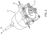
Figure 2 is perspective view of an exemplarily embodiment of an energy recovery element of the energy recovery system according to the invention; -
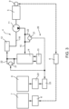
Figure 3 is a schematic functional representation of a vehicular system comprising an energy recovery system according to a first embodiment of the invention; and -
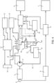
Figure 4 is a schematic functional representation of a vehicular system comprising an energy recovery system according to a second embodiment of the invention. -
Figure 1 discloses awork vehicle 1 such as an earth moving machine, e.g. a scraper provided, as per se known, with a body 2 configured to move viaground engaging means 3 on ground. -
Vehicle 1 comprises ahydraulic arrangement 4 configured to allow operation of different operational elements of the vehicle, such as boom or bucket. Thehydraulic arrangement 4 is operated by atorque source 5 such as an internal combustion engine as better described below. - The
work vehicle 1 further comprises main energy storing means 6 such as a battery pack, configured to store electrical energy. - The work vehicle then comprises
machine systems 7 andservice devices 8 electrically connected to the main energy storing means 6 to use the electrical energy stored therein for their operation. Non limitative examples ofmachine systems 7 comprises the AC/DC converter, ECU, engine controller, solenoid valves while non limitative examples of service devices are the lighting systems, cameras, monitors, 12V connectors, sensor means, phone chargers. - In particular, the main energy storing means 6 are electrically connected to the
machine systems 7 via main controller means 6', such as inverter or any other electrical energy controller, in order to control the energy flow between the main energy storing means 6 andmachine systems 7. -
Work vehicle 1 further comprises anelectric machine 9 that is coupled to thetorque source 5 and configured to be carried by this latter to generate electrical energy from the torque provide bytorque source 5. Theelectric machine 9 is advantageously electrically connected to the energy main storing means 6 to allow electrical energy exchange. - The
hydraulic arrangement 4 comprises essentially pump means 11 configured to pressurize an operative fluid, such as oil, from atank 12 towardsremote systems 13 whose fluid flow is controlled by avalve arrangement 14. Examples of suchremote systems 13 are the different actuators, such as cylinders, of the work vehicle. - The pump means 11 are therefore fluidly interposed between a
high pressure conduit 15 between the pump means 11 and thevalve arrangement 14 towardstank 12 and alow pressure conduit 16 between thetank 12 and the pump means 11. - The
hydraulic arrangement 4 further comprises anenergy recovery system 20 configured to generate electrical energy from the fluid flowing between pump means 11,valve arrangement 14 and/ortank 12. In detail theenergy recovery system 20 is configured to generate electrical energy from the fluid flowing inhigh pressure conduit 15 or, possibly, in low pressure conduit 17. - The
energy recovery system 20 advantageously comprises energy generator means 21 fluidly interposed in parallel to one of conduits of thehydraulic arrangement 4 and in particular interposed on by-pass conduits 22 onhigh pressure conduit 15. Alternatively, as said, the same arrangement may be realized in low pressure conduit 17. - In the embodiment of
figure 3 , a pair of energy generator means 21 are present upstream and downstream tovalve arrangement 14. - The
energy recovery system 20 comprises auxiliary energy storing means 23 electrically connected to the energy generator means 21 in order to receive the electrical energy generated by these latter. - In particular, the energy generation means 21 are integrated into the conduit of the
hydraulic arrangement 4. -
Figure 2 discloses an exemplarily embodiment of such energy generation means 21 comprising a motive element 21' that is carried by an electric machine (not shown) electrically connected to auxiliary energy storing means 23 and housed within the space ofconduit 22. - The above-mentioned
service devices 8 are connected, preferably via auxiliary controller means 23', such as inverter or any other electrical energy controller, to the auxiliary energy storing means 23. - The operation of the above described first embodiment of the invention is the following.
- During the operation of the
work vehicle 1, the internal combustion engine/source torque 5 carries theelectric machine 9 and the pump means 11. Theelectric machine 9 generates electrical energy stored in the main energy storing means 6 and used, via supervision of main controller means 6', bymachine systems 7 of thework vehicle 1. Pump means 11 provide high pressure fluid towardsvalve arrangement 14, i.e. toremote systems 13. During such high pressure fluid provision, part of the oil flow passes throughbypass conduits 22 and then through energy generation means 21. In this way, electrical energy is generated and collected into auxiliary energy storing means 23 and used, via supervision of auxiliary controller means 23', byservice devices 8 of thework vehicle 1. - In the embodiment of
figure 4 , the above described vehicular system differs in that the main and auxiliary controllers 6' and 23' are electrically connected one with the other thereby allowing possible electric energy exchange between the elements connected to these latter. - Moreover, the
hydraulic arrangement 4 comprises acollector 30 configured to collect all discharges toremote systems 13 of thework vehicle 1. - The
collector 30 is fluidly connected totank 12 via aconduit 31 and thehydraulic arrangement 4 further comprises valve means 32 configured to selectively allow direct fluid connection ofcollector 30 totank 12 viaconduit 31 or connection via aparallel conduit 33 and energy generation means 21 fluidly interposed on such parallel conduit. - In particular, therefore, valve means 32 are configured to allow at least two limit configurations, a first limit configuration wherein the
collector 30 is isolated from energy generation means 21 and all fluid flow passes viaconduit 31 totank 12 and a second limit configuration wherein all fluid flow passes viaparallel conduit 33 through energy generation means 21 totank 12. - In the shown embodiment, valve means 32 are three ways two positions valve, preferably an electrically controlled valve.
- In particular, valve means 32 are controlled by a signal provided by one of the controller means 6', 23', and in the shown embodiment by the auxiliary controller means 23' that are therefore provided with elaboration means configured to collect and elaborate data to provide a control signal for controlling
valve means 32. - In further detail, the control signal provided by auxiliary controller means 23' is elaborated on the base of sensor data retrieved by sensor means provided into the vehicular system and configured to collect at least one among the following parameters:
- Pressure of the flow of fluid coming from
collector 30; - Error signal related to an anomaly of operation of energy generation means 21 such as a mechanical lock or an abnormal temperature;
- Temperature or state of charge of auxiliary energy storage means 23; and
- Required energy by
service devices 8. - The operation of the above described second embodiment of the invention is the following.
- During the operation of the
work vehicle 1, the internal combustion engine/source torque 5 carries theelectric machine 9 and the pump means 11. Theelectric machine 9 generates electrical energy stored in the main energy storing means 6 and used, via supervision of main controller means 6', bymachine systems 7 of thework vehicle 1. Return fluid fromremote devices 13 is collected intocollector 30 and then sent intotank 12 directly or via interposition of energy generation means 21 according to the control signal provided by auxiliary controller means 23' to valve means 32. If energy is generated, then it can be stored, as in the previous embodiment, in the auxiliary energy storage means 23 and used byservice devices 8. According to data retrieved by sensor means listed above, the auxiliary controller means 23' may change the status of actuation of valve means 32. If needed, furthermore, controller means 23' and 6' may allow energy passage directly between main energy storage means 6 andservice devices 8. - In view of the above, the present invention further relates to a control method for controlling an energy generation system in a vehicular system as described in the above second embodiment and comprising the following steps:
- i. Receiving parameters related to the operation of the elements of the vehicular system;
- ii. Elaborating parameters retrieved at step i) to determine a quantity of electrical energy to be produced by energy generation means (21);
- iii. Associating the quantity of electrical energy to a value of flow to of fluid to be provided to energy generation means (21);
- iv. Elaborating a control signal related to the flow value elaborated at step iii) to control valve means (32).
- In particular, as said, the aforementioned parameters comprise at least one among:
- Pressure of the flow of fluid coming from
collector 30; - Error signal related to an anomaly of operation of energy generation means 21 such as a mechanical lock or an abnormal temperature;
- Temperature or state of charge of auxiliary energy storage means 23; and
- Required energy by
service devices 8. - The above-mentioned steps may be executed by one of the controller means 23', 6' comprising elaboration means configured to retrieved the sensor means data and allow their elaboration.
- In view of the foregoing, the advantages of a vehicular systema and a work vehicle according to the invention are apparent.
- Thanks to the proposed energy generation means it is possible to recovery part of the energy wasted during the fluid motion in the hydraulic circuit.
- Furthermore, the energy recovered by the above energy generation means can be used to fed service devices without using the energy of main energy storing means.
- In this way the load consumed by electric machine carried by torque source is reduced and then it is reduced the vehicular fuel consumption.
- Moreover, in the embodiment provided with the collector and valve means it is possible to selectively allow or exclude the energy generation means according to vehicle need and operation.
- Accordingly, the proposed vehicular system is further versatile. Such versatility is moreover increased thanks to electrical connection between auxiliary and main energy storing means.
- It is clear that modifications can be made to the described vehicular systema and a work vehicle which do not extend beyond the scope of protection defined by the claims.
- Clearly number and positioning of energy generators and their typology may differ with respect to the described and shown one.
- Similarly the controller typology and number may vary according to the peculiar need of the vehicular system.
- Furthermore, sensor data used for elaborating the control signal for actuating valve means may differ with respect to the described one.
Claims (16)
- Vehicular system for a work vehicle (1), said vehicular system comprising:- a torque source (5);- an electric machine (9) carried by said torque source (5) and configured to generate electrical energy in function of the torque provided by said torque source (5),- main energy storing means (6) electrically connected to said electric machine (9) and configured to store electrical energy produced by this latter;- a hydraulic arrangement (4) comprising pump means (11) carried by said torque source (5), a valve arrangement (14) and a tank (12) fluidly connected to said pump means (11), said valve arrangement (14) allowing the fluidic connection of remote systems (13) of said work vehicle (1) to said tank (12) and said pump means (11),said vehicular system comprising an energy recovery system (20) configured to generate electrical energy from the movement of the fluid flowing between pump means (11), valve arrangement (14) and/or tank (12).
- Vehicular system according to claim 1, wherein said pump means (11) are connected to said valve arrangement (14) and to said tank (12) via a high pressure conduit (15), said energy recovery system (20) being configured to generate electrical energy from the movement of the fluid flowing into said high pressure conduit (15).
- Vehicular system according to claim 1, wherein said energy recovery system (20) comprises energy generation means (21) fluidly interposed in parallel to one of conduits of hydraulic arrangement (4).
- Vehicular system according to claim 1, wherein said energy generation means (21) are integrated into said conduit.
- Vehicular system according to claim 3, wherein said energy recovery system (20) further comprises auxiliary energy storing means (23) electrically connected to said energy generation means (21) and configured to store electrical energy produced by these latter.
- Vehicular system according to claim 5, wherein said auxiliary energy storing means (23) are electrically connected to service devices (8) of said work vehicle (1) and wherein said main energy storing means (6) are electrically connected to machine systems (7) of said work vehicle (1).
- Vehicular system according to claim 5, wherein said auxiliary energy storing means (23') are electrically connected to said main energy storing means (6).
- Vehicular system according to any of the preceding claims, further comprising a collector (30) fluidly interposed between said remote systems (13) of said work vehicle (1) and said tank (12) and configured to collect the discharge of said remote systems (13), said energy recovery system (20) being selectively fluidly interposed between said collector (30) and said tank (12).
- Vehicular system according to claim 8, further comprising valve means (32) configured to selectively allow direct fluid connection of said collector (30) to said tank (12) via a conduit (31) or connection via a parallel conduit (33) wherein energy generation means (21) are fluidly interposed therethrough.
- Vehicular system according to claim 9, wherein said valve means (32) comprise an electric controlled valve.
- Vehicular system according to claim 10, wherein said valve means (32) are controlled by a control signal elaborated on the parameters related to the operation of the elements of said vehicular system.
- Vehicular system according to claim 11, wherein said parameters comprises at least one among:• Data retrieved from sensor means configured to detect pressure of the flow of fluid coming from said collector (30) ;• Data retrieved from sensor means configured to detect to an anomaly of operation of energy generation means (21);• Data retrieved from sensor means configured to detect temperature or state of charge of said auxiliary energy storage means (23); and• Energy request retrieved by said service devices (8).
- Vehicular system according to claim 11 or 12, comprising an electronic control unit provided with elaboration means configured to acquire said parameters and elaborate said control signal for said valve means (32).
- Vehicular system according to claim 13, wherein said main and auxiliary storing means (6, 23) are controlled by respective main and auxiliary controller means (6', 23'), said electronic control unit being one between said main and auxiliary controller means (6', 23').
- Control method for controlling an energy generation system (20) in a vehicular system as claimed in claim 13 and comprising the following steps:v. Receiving parameters related to the operation of the elements of said vehicular system;vi. Elaborating parameters retrieved at step i) to determine a quantity of electrical energy to be produced by energy generation means (21);vii. Associating the quantity of electrical energy to a value of flow to of fluid to be provided to energy generation means (21);viii. Elaborating a control signal related to the flow value elaborated at step iii) to control said valve means (32).
- Work vehicle (1) comprising a vehicular system according to any of claims 1 to 14.
Applications Claiming Priority (1)
| Application Number | Priority Date | Filing Date | Title |
|---|---|---|---|
| IT102023000009612A IT202300009612A1 (en) | 2023-05-12 | 2023-05-12 | ENERGY RECOVERY SYSTEM FOR A VEHICLE SYSTEM OF A WORK VEHICLE |
Publications (2)
| Publication Number | Publication Date |
|---|---|
| EP4461579A1 true EP4461579A1 (en) | 2024-11-13 |
| EP4461579B1 EP4461579B1 (en) | 2026-04-15 |
Family
ID=87136459
Family Applications (1)
| Application Number | Title | Priority Date | Filing Date |
|---|---|---|---|
| EP24172852.6A Active EP4461579B1 (en) | 2023-05-12 | 2024-04-26 | Energy recovery system for a vehicular system of a work vehicle |
Country Status (2)
| Country | Link |
|---|---|
| EP (1) | EP4461579B1 (en) |
| IT (1) | IT202300009612A1 (en) |
Citations (8)
| Publication number | Priority date | Publication date | Assignee | Title |
|---|---|---|---|---|
| US6708787B2 (en) * | 2001-03-12 | 2004-03-23 | Komatsu Ltd. | Hybrid construction equipment |
| JP2006336848A (en) * | 2005-06-06 | 2006-12-14 | Shin Caterpillar Mitsubishi Ltd | Fluid pressure circuit for working machine |
| EP2400652A1 (en) * | 2009-02-18 | 2011-12-28 | Sumitomo Heavy Industries, LTD. | Hybrid shovel |
| US8659177B2 (en) * | 2011-02-03 | 2014-02-25 | Hitachi Construction Machinery Co., Ltd. | Motive power regeneration system for working machine |
| US20150086315A1 (en) * | 2013-09-24 | 2015-03-26 | Kobelco Construction Machinery Co., Ltd. | Hybrid construction machine |
| US9598842B2 (en) * | 2012-02-17 | 2017-03-21 | Hitachi Construction Machinery Co., Ltd. | Construction machinery |
| US10161108B2 (en) * | 2014-01-28 | 2018-12-25 | Hitachi Construction Machinery Co., Ltd. | Hydraulic fluid energy recovery system for work |
| KR20230008522A (en) * | 2021-07-07 | 2023-01-16 | 울산대학교 산학협력단 | An energy regeneration excavator system using hydraulic flywheel accumulator, hydraulic motor and generator |
-
2023
- 2023-05-12 IT IT102023000009612A patent/IT202300009612A1/en unknown
-
2024
- 2024-04-26 EP EP24172852.6A patent/EP4461579B1/en active Active
Patent Citations (8)
| Publication number | Priority date | Publication date | Assignee | Title |
|---|---|---|---|---|
| US6708787B2 (en) * | 2001-03-12 | 2004-03-23 | Komatsu Ltd. | Hybrid construction equipment |
| JP2006336848A (en) * | 2005-06-06 | 2006-12-14 | Shin Caterpillar Mitsubishi Ltd | Fluid pressure circuit for working machine |
| EP2400652A1 (en) * | 2009-02-18 | 2011-12-28 | Sumitomo Heavy Industries, LTD. | Hybrid shovel |
| US8659177B2 (en) * | 2011-02-03 | 2014-02-25 | Hitachi Construction Machinery Co., Ltd. | Motive power regeneration system for working machine |
| US9598842B2 (en) * | 2012-02-17 | 2017-03-21 | Hitachi Construction Machinery Co., Ltd. | Construction machinery |
| US20150086315A1 (en) * | 2013-09-24 | 2015-03-26 | Kobelco Construction Machinery Co., Ltd. | Hybrid construction machine |
| US10161108B2 (en) * | 2014-01-28 | 2018-12-25 | Hitachi Construction Machinery Co., Ltd. | Hydraulic fluid energy recovery system for work |
| KR20230008522A (en) * | 2021-07-07 | 2023-01-16 | 울산대학교 산학협력단 | An energy regeneration excavator system using hydraulic flywheel accumulator, hydraulic motor and generator |
Also Published As
| Publication number | Publication date |
|---|---|
| IT202300009612A1 (en) | 2024-11-12 |
| EP4461579B1 (en) | 2026-04-15 |
Similar Documents
| Publication | Publication Date | Title |
|---|---|---|
| US8186154B2 (en) | Rotary flow control valve with energy recovery | |
| US6628006B2 (en) | System and method for recovering potential energy of a hydrogen gas fuel supply for use in a vehicle | |
| JP4480908B2 (en) | Hybrid excavator | |
| EP1126086B1 (en) | Excavator | |
| CN100538087C (en) | Power system and working machinery using the power system | |
| CN103154390B (en) | It is designed to the jumbo operated with basic repetitive cycling | |
| KR101947301B1 (en) | Pressure oil energy recovery device of working machine | |
| CN100538086C (en) | Power system and working machinery using the power system | |
| CN109764027B (en) | Electro-hydraulic working vehicle with energy recovery function | |
| KR101256483B1 (en) | Hybrid working machine | |
| US20100236232A1 (en) | Drive for a Hydraulic Excavator | |
| US6591926B2 (en) | System and method for recovering energy of a hydrogen gas fuel supply for use in a vehicle | |
| US20160186785A1 (en) | Hydraulic energy recovery system | |
| KR20160105892A (en) | Hydraulic energy regeneration apparatus for machinery | |
| KR20150069025A (en) | Hybrid work machine | |
| US9037357B2 (en) | Control system for hybrid construction machine | |
| US20160145833A1 (en) | System and method for controlling power in machine having hydraulic devices | |
| US20040000141A1 (en) | Hydraulic energy recovering/regenerating apparatus | |
| KR101155785B1 (en) | Hybrid system of an excavator | |
| CN104912137A (en) | Excavator hydraulic system with energy feedback function | |
| EP4461579B1 (en) | Energy recovery system for a vehicular system of a work vehicle | |
| JP5647926B2 (en) | Power storage device | |
| CN106958561B (en) | Dual power supply type engineering machinery | |
| US12366053B2 (en) | Distributed pump architecture for multifunctional machines | |
| US12537472B2 (en) | Hydraulic load management for electric motor driven systems |
Legal Events
| Date | Code | Title | Description |
|---|---|---|---|
| PUAI | Public reference made under article 153(3) epc to a published international application that has entered the european phase |
Free format text: ORIGINAL CODE: 0009012 |
|
| STAA | Information on the status of an ep patent application or granted ep patent |
Free format text: STATUS: THE APPLICATION HAS BEEN PUBLISHED |
|
| AK | Designated contracting states |
Kind code of ref document: A1 Designated state(s): AL AT BE BG CH CY CZ DE DK EE ES FI FR GB GR HR HU IE IS IT LI LT LU LV MC ME MK MT NL NO PL PT RO RS SE SI SK SM TR |
|
| STAA | Information on the status of an ep patent application or granted ep patent |
Free format text: STATUS: REQUEST FOR EXAMINATION WAS MADE |
|
| 17P | Request for examination filed |
Effective date: 20250513 |
|
| GRAP | Despatch of communication of intention to grant a patent |
Free format text: ORIGINAL CODE: EPIDOSNIGR1 |
|
| STAA | Information on the status of an ep patent application or granted ep patent |
Free format text: STATUS: GRANT OF PATENT IS INTENDED |
|
| INTG | Intention to grant announced |
Effective date: 20250702 |
|
| GRAJ | Information related to disapproval of communication of intention to grant by the applicant or resumption of examination proceedings by the epo deleted |
Free format text: ORIGINAL CODE: EPIDOSDIGR1 |
|
| STAA | Information on the status of an ep patent application or granted ep patent |
Free format text: STATUS: REQUEST FOR EXAMINATION WAS MADE |
|
| GRAP | Despatch of communication of intention to grant a patent |
Free format text: ORIGINAL CODE: EPIDOSNIGR1 |
|
| STAA | Information on the status of an ep patent application or granted ep patent |
Free format text: STATUS: GRANT OF PATENT IS INTENDED |
|
| INTC | Intention to grant announced (deleted) | ||
| INTG | Intention to grant announced |
Effective date: 20251126 |
|
| GRAS | Grant fee paid |
Free format text: ORIGINAL CODE: EPIDOSNIGR3 |
|
| GRAA | (expected) grant |
Free format text: ORIGINAL CODE: 0009210 |
|
| STAA | Information on the status of an ep patent application or granted ep patent |
Free format text: STATUS: THE PATENT HAS BEEN GRANTED |
|
| AK | Designated contracting states |
Kind code of ref document: B1 Designated state(s): AL AT BE BG CH CY CZ DE DK EE ES FI FR GB GR HR HU IE IS IT LI LT LU LV MC ME MK MT NL NO PL PT RO RS SE SI SK SM TR |
|
| REG | Reference to a national code |
Ref country code: CH Ref legal event code: F10 Free format text: ST27 STATUS EVENT CODE: U-0-0-F10-F00 (AS PROVIDED BY THE NATIONAL OFFICE) Effective date: 20260415 |
|
| REG | Reference to a national code |
Ref country code: DE Ref legal event code: R096 Ref document number: 602024003906 Country of ref document: DE |
|
| REG | Reference to a national code |
Ref country code: IE Ref legal event code: FG4D |
|
| PGFP | Annual fee paid to national office [announced via postgrant information from national office to epo] |
Ref country code: IT Payment date: 20260430 Year of fee payment: 3 |
|
| PGFP | Annual fee paid to national office [announced via postgrant information from national office to epo] |
Ref country code: DE Payment date: 20260421 Year of fee payment: 3 |
|
| PGFP | Annual fee paid to national office [announced via postgrant information from national office to epo] |
Ref country code: AT Payment date: 20260714 Year of fee payment: 3 |
|
| PGFP | Annual fee paid to national office [announced via postgrant information from national office to epo] |
Ref country code: FR Payment date: 20260423 Year of fee payment: 3 |