EP4461573A1 - Hybrid refrigeration system, control method thereof, and transportation refrigeration vehicle - Google Patents
Hybrid refrigeration system, control method thereof, and transportation refrigeration vehicle Download PDFInfo
- Publication number
- EP4461573A1 EP4461573A1 EP24172810.4A EP24172810A EP4461573A1 EP 4461573 A1 EP4461573 A1 EP 4461573A1 EP 24172810 A EP24172810 A EP 24172810A EP 4461573 A1 EP4461573 A1 EP 4461573A1
- Authority
- EP
- European Patent Office
- Prior art keywords
- refrigeration
- refrigeration device
- cargo box
- temperature
- hybrid
- Prior art date
- Legal status (The legal status is an assumption and is not a legal conclusion. Google has not performed a legal analysis and makes no representation as to the accuracy of the status listed.)
- Granted
Links
Images

Classifications
-
- F—MECHANICAL ENGINEERING; LIGHTING; HEATING; WEAPONS; BLASTING
- F25—REFRIGERATION OR COOLING; COMBINED HEATING AND REFRIGERATION SYSTEMS; HEAT PUMP SYSTEMS; MANUFACTURE OR STORAGE OF ICE; LIQUEFACTION SOLIDIFICATION OF GASES
- F25B—REFRIGERATION MACHINES, PLANTS OR SYSTEMS; COMBINED HEATING AND REFRIGERATION SYSTEMS; HEAT PUMP SYSTEMS
- F25B49/00—Arrangement or mounting of control or safety devices
- F25B49/02—Arrangement or mounting of control or safety devices for compression type machines, plants or systems
-
- F—MECHANICAL ENGINEERING; LIGHTING; HEATING; WEAPONS; BLASTING
- F25—REFRIGERATION OR COOLING; COMBINED HEATING AND REFRIGERATION SYSTEMS; HEAT PUMP SYSTEMS; MANUFACTURE OR STORAGE OF ICE; LIQUEFACTION SOLIDIFICATION OF GASES
- F25D—REFRIGERATORS; COLD ROOMS; ICE-BOXES; COOLING OR FREEZING APPARATUS NOT OTHERWISE PROVIDED FOR
- F25D29/00—Arrangement or mounting of control or safety devices
- F25D29/003—Arrangement or mounting of control or safety devices for movable devices
-
- B—PERFORMING OPERATIONS; TRANSPORTING
- B60—VEHICLES IN GENERAL
- B60H—ARRANGEMENTS OF HEATING, COOLING, VENTILATING OR OTHER AIR-TREATING DEVICES SPECIALLY ADAPTED FOR PASSENGER OR GOODS SPACES OF VEHICLES
- B60H1/00—Heating, cooling or ventilating devices
- B60H1/32—Cooling devices
- B60H1/3201—Cooling devices using absorption or adsorption
-
- B—PERFORMING OPERATIONS; TRANSPORTING
- B60—VEHICLES IN GENERAL
- B60H—ARRANGEMENTS OF HEATING, COOLING, VENTILATING OR OTHER AIR-TREATING DEVICES SPECIALLY ADAPTED FOR PASSENGER OR GOODS SPACES OF VEHICLES
- B60H1/00—Heating, cooling or ventilating devices
- B60H1/00357—Air-conditioning arrangements specially adapted for particular vehicles
-
- B—PERFORMING OPERATIONS; TRANSPORTING
- B60—VEHICLES IN GENERAL
- B60H—ARRANGEMENTS OF HEATING, COOLING, VENTILATING OR OTHER AIR-TREATING DEVICES SPECIALLY ADAPTED FOR PASSENGER OR GOODS SPACES OF VEHICLES
- B60H1/00—Heating, cooling or ventilating devices
- B60H1/00421—Driving arrangements for parts of a vehicle air-conditioning
-
- B—PERFORMING OPERATIONS; TRANSPORTING
- B60—VEHICLES IN GENERAL
- B60H—ARRANGEMENTS OF HEATING, COOLING, VENTILATING OR OTHER AIR-TREATING DEVICES SPECIALLY ADAPTED FOR PASSENGER OR GOODS SPACES OF VEHICLES
- B60H1/00—Heating, cooling or ventilating devices
- B60H1/00642—Control systems or circuits; Control members or indication devices for heating, cooling or ventilating devices
- B60H1/00735—Control systems or circuits characterised by their input, i.e. by the detection, measurement or calculation of particular conditions, e.g. signal treatment, dynamic models
-
- B—PERFORMING OPERATIONS; TRANSPORTING
- B60—VEHICLES IN GENERAL
- B60H—ARRANGEMENTS OF HEATING, COOLING, VENTILATING OR OTHER AIR-TREATING DEVICES SPECIALLY ADAPTED FOR PASSENGER OR GOODS SPACES OF VEHICLES
- B60H1/00—Heating, cooling or ventilating devices
- B60H1/00642—Control systems or circuits; Control members or indication devices for heating, cooling or ventilating devices
- B60H1/00814—Control systems or circuits characterised by their output, for controlling particular components of the heating, cooling or ventilating installation
- B60H1/00878—Control systems or circuits characterised by their output, for controlling particular components of the heating, cooling or ventilating installation the components being temperature regulating devices
-
- B—PERFORMING OPERATIONS; TRANSPORTING
- B60—VEHICLES IN GENERAL
- B60H—ARRANGEMENTS OF HEATING, COOLING, VENTILATING OR OTHER AIR-TREATING DEVICES SPECIALLY ADAPTED FOR PASSENGER OR GOODS SPACES OF VEHICLES
- B60H1/00—Heating, cooling or ventilating devices
- B60H1/32—Cooling devices
- B60H1/3201—Cooling devices using absorption or adsorption
- B60H1/32011—Cooling devices using absorption or adsorption using absorption, e.g. using Li-Br and water
-
- B—PERFORMING OPERATIONS; TRANSPORTING
- B60—VEHICLES IN GENERAL
- B60H—ARRANGEMENTS OF HEATING, COOLING, VENTILATING OR OTHER AIR-TREATING DEVICES SPECIALLY ADAPTED FOR PASSENGER OR GOODS SPACES OF VEHICLES
- B60H1/00—Heating, cooling or ventilating devices
- B60H1/32—Cooling devices
- B60H1/3204—Cooling devices using compression
-
- B—PERFORMING OPERATIONS; TRANSPORTING
- B60—VEHICLES IN GENERAL
- B60P—VEHICLES ADAPTED FOR LOAD TRANSPORTATION OR TO TRANSPORT, TO CARRY, OR TO COMPRISE SPECIAL LOADS OR OBJECTS
- B60P3/00—Vehicles adapted to transport, to carry or to comprise special loads or objects
- B60P3/20—Refrigerated goods vehicles
-
- F—MECHANICAL ENGINEERING; LIGHTING; HEATING; WEAPONS; BLASTING
- F25—REFRIGERATION OR COOLING; COMBINED HEATING AND REFRIGERATION SYSTEMS; HEAT PUMP SYSTEMS; MANUFACTURE OR STORAGE OF ICE; LIQUEFACTION SOLIDIFICATION OF GASES
- F25B—REFRIGERATION MACHINES, PLANTS OR SYSTEMS; COMBINED HEATING AND REFRIGERATION SYSTEMS; HEAT PUMP SYSTEMS
- F25B19/00—Machines, plants or systems, using evaporation of a refrigerant but without recovery of the vapour
-
- F—MECHANICAL ENGINEERING; LIGHTING; HEATING; WEAPONS; BLASTING
- F25—REFRIGERATION OR COOLING; COMBINED HEATING AND REFRIGERATION SYSTEMS; HEAT PUMP SYSTEMS; MANUFACTURE OR STORAGE OF ICE; LIQUEFACTION SOLIDIFICATION OF GASES
- F25B—REFRIGERATION MACHINES, PLANTS OR SYSTEMS; COMBINED HEATING AND REFRIGERATION SYSTEMS; HEAT PUMP SYSTEMS
- F25B27/00—Machines, plants or systems, using particular sources of energy
-
- F—MECHANICAL ENGINEERING; LIGHTING; HEATING; WEAPONS; BLASTING
- F25—REFRIGERATION OR COOLING; COMBINED HEATING AND REFRIGERATION SYSTEMS; HEAT PUMP SYSTEMS; MANUFACTURE OR STORAGE OF ICE; LIQUEFACTION SOLIDIFICATION OF GASES
- F25D—REFRIGERATORS; COLD ROOMS; ICE-BOXES; COOLING OR FREEZING APPARATUS NOT OTHERWISE PROVIDED FOR
- F25D11/00—Self-contained movable devices, e.g. domestic refrigerators
- F25D11/003—Transport containers
-
- F—MECHANICAL ENGINEERING; LIGHTING; HEATING; WEAPONS; BLASTING
- F25—REFRIGERATION OR COOLING; COMBINED HEATING AND REFRIGERATION SYSTEMS; HEAT PUMP SYSTEMS; MANUFACTURE OR STORAGE OF ICE; LIQUEFACTION SOLIDIFICATION OF GASES
- F25B—REFRIGERATION MACHINES, PLANTS OR SYSTEMS; COMBINED HEATING AND REFRIGERATION SYSTEMS; HEAT PUMP SYSTEMS
- F25B2327/00—Compressor driving means
- F25B2327/10—Compressor driving means using engines
- F25B2327/12—Compressor driving means using engines using internal combustion engines
Definitions
- the present invention relates to the field of refrigeration devices, and in particular to a hybrid refrigeration system, a control method thereof, and a transportion refrigeration vehicle.
- the transportation refrigeration vehicles used in existing cold chain transportation generally use mechanical refrigeration devices.
- the mechanical refrigeration device In order to reduce the temperature inside the cargo box to a set temperature quickly, the mechanical refrigeration device needs to have a large refrigeration capacity. Therefore, the mechanical refrigeration device itself and the devices that power it, such as combustion engines, lithium batteries, or fuel cells, need to be designed with a larger volume and weight.
- liquid nitrogen refrigeration systems can achieve rapid cooling, but their cost is high and they are not suitable for long-distance transportation.
- the object of the present application is to solve or at least alleviate the problems existing in the prior art.
- a hybrid refrigeration system for a transportation refrigeration vehicle comprising:
- a selectable range of the first threshold is, for example, 2 °C -10 °C, such as 3 °C -8 °C.
- the first refrigeration device comprises a liquid nitrogen storage tank and a liquid nitrogen release control valve, where the first refrigeration device regulates the temperature of the cargo box by converting liquid nitrogen into nitrogen gas and transporting it to the cargo box, or the first refrigeration device further comprises a first cargo box heat exchanger, where the first refrigeration device regulates the temperature of the cargo box by converting the liquid nitrogen into nitrogen gas, passing it through the first cargo box heat exchanger and then discharging it to the environment.
- the second refrigeration device comprises a compressor, a condenser, a throttling device, and a second cargo box heat exchanger.
- the second refrigeration device is powered by a combustion engine, a lithium battery, or fuel cells.
- the first refrigeration device and the second refrigeration device share the same cargo box heat exchanger.
- the other of the first refrigeration device or the second refrigeration device alone serves as a backup refrigeration device for temperature regulation of the cargo box.
- a transportation refrigeration vehicle comprising a hybrid refrigeration system according to the various embodiments, wherein the transportation refrigeration vehicle is powered by a combustion engine, a lithium battery, or fuel cells, where the hybrid refrigeration system and the transportation refrigeration vehicle share an energy supply device or respectively comprise independent energy supply devices.
- a control method for a hybrid refrigeration system comprising:
- the method further comprises: turning off the first refrigeration device and using the second refrigeration device to maintain the temperature of the cargo box when the first refrigeration device is started and the set temperature is reached, or when the difference between the temperature of the cargo box and the set temperature is less than the first threshold.
- a selectable range of the first threshold is, for example, 2 °C -10 °C, such as 3 °C -8 °C.
- the device and method according to the embodiments of the present invention can reduce the requirement for the capacity of the mechanical refrigeration device on the vehicle, and thus reduce the weight and volume of the mechanical refrigeration device.
- the transportation refrigeration vehicle can be used for cold chain transportation, including food, drugs, and the like, which mainly comprise a tractor 1, a trailer 2, and a cargo box 3 arranged on a platform defined by the tractor 1 and the trailer 2, with its interior used to store goods that need cold chain transportation.
- the transportation refrigeration vehicle also comprises a hybrid refrigeration system according to various embodiments of the present invention.
- the hybrid refrigeration system comprises: a first refrigeration device 5 for regulating the temperature of the cargo box 3, where the first refrigeration device 5 is a liquid nitrogen based refrigeration device; a second refrigeration device 4 for regulating the temperature of the cargo box 3, where the second refrigeration device 4 is a mechanical refrigeration device; and a controller connected to the first refrigeration device 5 and the second refrigeration device 4; wherein, the controller is configured to determine whether the difference between the temperature of the cargo box and a set temperature is greater than or equal to a first threshold when receiving a refrigeration demand for the cargo box; if so, start the first refrigeration device 5 alone or start both the first refrigeration device 5 and the second refrigeration device 4 simultaneously; and if not, start the second refrigeration device 4 alone.
- the first refrigeration device 5 based on liquid nitrogen can be used to reduce the temperature of the cargo box quickly when the difference between the temperature of the cargo box and the set temperature is large, while the second refrigeration device 4 is used to assist in cooling and maintaining temperature. This reduces the requirement for the refrigeration capacity of the second refrigeration device 4, thereby reducing the weight of various components of the second refrigeration device 4 based on mechanical refrigeration as well as the weight of the energy supply devices that power them.
- the selectable range of the first threshold is, for example, 2 °C -10 °C, and optionally, between, for example, 3 °C -8 °C.
- the controller may be further configured to turn off the first refrigeration device 5 and use the second refrigeration device 4 to maintain the temperature of the cargo box when using the first refrigeration device 5 and the temperature of the cargo box is reduced to the set temperature.
- the controller can otherwise be configured to turn off the first refrigeration device 5 when the difference between the temperature of the cargo box and the set temperature is less than the first threshold, and then the second refrigeration device 4 alone regulates the temperature of the cargo box.
- the second refrigeration device 4 can be turned on at any time after receiving the refrigeration demand but before the first refrigeration device 5 being turned off.
- the second refrigeration device 4 can be turned on simultaneously with the first refrigeration device 5 to achieve the fastest cooling, or turned on when the first refrigeration device 5 is turned off, thereby saving energy.
- the rated capacity, weight, and volume of the second refrigeration device 4 can be reduced compared to conventional mechanical refrigeration devices.
- the time required to lower the temperature of the cargo box to its set point when the refrigeration device is first started can also be reduced.
- the first refrigeration device 5 comprises a liquid nitrogen storage tank 51, a liquid nitrogen storage sink 52, a liquid nitrogen release control valve 53, a liquid nitrogen transfer pipeline 54, and a first cargo box heat exchanger 55.
- the first refrigeration device 5 regulates the temperature of the cargo box by converting the liquid nitrogen in the liquid nitrogen storage tank 51 into a gaseous state through the control valve 53, and exchanging heat with the air in the cargo compartment through the first cargo box heat exchanger 55 and then discharging it into the environment.
- the first refrigeration device 5 can regulate the temperature of the cargo box by converting the liquid nitrogen into a gaseous state through the control valve 53 and directly transporting it to the interior of the cargo box 3.
- liquid nitrogen storage tank 51 of the first refrigeration device 5 is arranged in the trailer 2 below the cargo box 3, and the trailer 2 may comprise a liquid nitrogen replenishment interface to replenish liquid nitrogen at the station, or the liquid nitrogen storage tank 51 may be replaced after the journey is completed.
- the second refrigeration device 4 may comprise a compressor, a condenser, a throttling device, and a second cargo box heat exchanger 41 connected into a circulating circuit. That is, the second refrigeration device 4 comprises a traditional refrigeration circuit comprising a compressor. In the embodiment of FIG. 1 , the second refrigeration device 4 is powered by a lithium battery 40. In alternative embodiments, fuel cells can also be used to replace the lithium battery 40. Or, as shown in FIG. 2 , the second refrigeration device 4 can be powered by a traditional combustion engine. As mentioned above, due to the addition of the first refrigeration device 5 based on liquid nitrogen, the capacity of components, such as the compressor, in the second refrigeration device 4 can be reduced, and their weight and volume can also be reduced.
- the weight and volume of the lithium battery 40 that powers the second refrigeration device 4 can also be reduced, which is crucial for vehicles powered by new energy sources such as lithium batteries, as the reduced weight means longer range.
- the tractor 1 may include an additional lithium battery or fuel cells 11, which can help to achieve a longer range for the transportion refrigeration vehicle when the weight of the second refrigeration device 4 is reduced.
- the second refrigeration device 4 may be arranged at the front of the cargo box 3, and the energy supply device 40 thereof may also be arranged in the trailer 2.
- the first refrigeration device 5 and the second refrigeration device 4 may also share the same cargo box heat exchanger 41.
- the cargo box heat exchanger 41 may comprise a first flow path for discharging nitrogen gas into the environment and a second flow path for the refrigerant in the second refrigeration device 4, as well as a fan for facilitating heat exchange between the air in the cargo box and the nitrogen gas in the first flow path and the refrigerant in the second flow path.
- the pipeline 54 of the first refrigeration device can be connected to the first flow path.
- the first refrigeration device 5 and the second refrigeration device 4 can serve as backup refrigeration systems for each other.
- the controller is configured to use the one in normal operation to regulate the temperature inside the cargo box 3 in the event of a failure of the first refrigeration device 5 or the second refrigeration device 4, thus allowing the hybrid refrigeration system to cope with the failure of a single refrigeration device and try to preserve important goods being transported in the cargo box.
- a transportation refrigeration vehicle may include a hybrid refrigeration system according to any of the above embodiments.
- the transportation refrigeration vehicle may be driven by a combustion engine, a lithium battery, or fuel cells, wherein the hybrid refrigeration system and the transportation refrigeration vehicle may share the combustion engine, the lithium battery, or the fuel cells, or they may have independent energy supply devices.
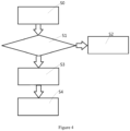
- the control method may comprise: S0: receiving a refrigeration demand for a cargo box; S1: determining whether the difference between the temperature of the cargo box and a set temperature is greater than or equal to a first threshold; if not, proceed to step S2 to start the second refrigeration device alone; and if yes, proceed to step S3 to start the first refrigeration device based on liquid nitrogen alone or start both the first refrigeration device based on liquid nitrogen and the second refrigeration device based on mechanical refrigeration simultaneously.
- the method further comprises: step S4: turning off the first refrigeration device and using the second refrigeration device to maintain the temperature of the cargo box when the first refrigeration device is started and the set temperature is reached, or when the difference between the temperature of the cargo box and the set temperature is less than the first threshold.
- the selectable range of the first threshold is, for example, 2 °C -10 °C, such as between 3 °C -8 °C.
Landscapes
- Engineering & Computer Science (AREA)
- Physics & Mathematics (AREA)
- Mechanical Engineering (AREA)
- Thermal Sciences (AREA)
- General Engineering & Computer Science (AREA)
- Chemical & Material Sciences (AREA)
- Combustion & Propulsion (AREA)
- Health & Medical Sciences (AREA)
- Public Health (AREA)
- Transportation (AREA)
- Devices That Are Associated With Refrigeration Equipment (AREA)
Abstract
Description
- The present invention relates to the field of refrigeration devices, and in particular to a hybrid refrigeration system, a control method thereof, and a transportion refrigeration vehicle.
- The transportation refrigeration vehicles used in existing cold chain transportation generally use mechanical refrigeration devices. In order to reduce the temperature inside the cargo box to a set temperature quickly, the mechanical refrigeration device needs to have a large refrigeration capacity. Therefore, the mechanical refrigeration device itself and the devices that power it, such as combustion engines, lithium batteries, or fuel cells, need to be designed with a larger volume and weight.
- On the other hand, liquid nitrogen refrigeration systems can achieve rapid cooling, but their cost is high and they are not suitable for long-distance transportation.
- The object of the present application is to solve or at least alleviate the problems existing in the prior art.
- According to a first aspect of the invention there is provided, a hybrid refrigeration system for a transportation refrigeration vehicle is provided, comprising:
- a first refrigeration device for regulating a temperature of a cargo box of the transportation refrigeration vehicle, wherein the first refrigeration device is a liquid nitrogen based refrigeration device; and
- a second refrigeration device for regulating the temperature of the cargo box of the transportation refrigeration vehicle, wherein the second refrigeration device is a mechanical refrigeration device;
- a controller connected to the first refrigeration device and the second refrigeration device;
- wherein, the controller is configured to determine whether a difference between the temperature of the cargo box and a set temperature is greater than or equal to a first threshold when receiving a refrigeration demand for the cargo box;
- if so, start the first refrigeration device alone or start both the first refrigeration device and the second refrigeration device simultaneously; and
- if not, start the second refrigeration device alone.
- Optionally, when the first refrigeration device is started and the set temperature is reached, or when the difference between the temperature of the cargo box and the set temperature is less than the first threshold, the first refrigeration device is turned off and the second refrigeration device is used to maintain the temperature of the cargo box. Optionally, a selectable range of the first threshold is, for example, 2 °C -10 °C, such as 3 °C -8 °C.
- Optionally, the first refrigeration device comprises a liquid nitrogen storage tank and a liquid nitrogen release control valve, where the first refrigeration device regulates the temperature of the cargo box by converting liquid nitrogen into nitrogen gas and transporting it to the cargo box, or the first refrigeration device further comprises a first cargo box heat exchanger, where the first refrigeration device regulates the temperature of the cargo box by converting the liquid nitrogen into nitrogen gas, passing it through the first cargo box heat exchanger and then discharging it to the environment.
- Optionally, the second refrigeration device comprises a compressor, a condenser, a throttling device, and a second cargo box heat exchanger.
- Optionally, the second refrigeration device is powered by a combustion engine, a lithium battery, or fuel cells.
- Optionally, the first refrigeration device and the second refrigeration device share the same cargo box heat exchanger.
- Optionally, in the event of a failure of either the first refrigeration device or the second refrigeration device, the other of the first refrigeration device or the second refrigeration device alone serves as a backup refrigeration device for temperature regulation of the cargo box.
- According to a second aspect of the invention there is provided, a transportation refrigeration vehicle comprising a hybrid refrigeration system according to the various embodiments is provided, wherein the transportation refrigeration vehicle is powered by a combustion engine, a lithium battery, or fuel cells, where the hybrid refrigeration system and the transportation refrigeration vehicle share an energy supply device or respectively comprise independent energy supply devices.
- According to a third aspect of the invention, a control method for a hybrid refrigeration system is further provided, comprising:
- determining whether a difference between a temperature of a cargo box and a set temperature is greater than or equal to a first threshold when receiving a refrigeration demand for the cargo box;
- if so, starting a first refrigeration device based on liquid nitrogen alone or starting both the first refrigeration device based on liquid nitrogen and a second refrigeration device based on mechanical refrigeration simultaneously; and
- if not, starting the second refrigeration device alone.
- Optionally, the method further comprises: turning off the first refrigeration device and using the second refrigeration device to maintain the temperature of the cargo box when the first refrigeration device is started and the set temperature is reached, or when the difference between the temperature of the cargo box and the set temperature is less than the first threshold. Optionally, a selectable range of the first threshold is, for example, 2 °C -10 °C, such as 3 °C -8 °C.
- The device and method according to the embodiments of the present invention can reduce the requirement for the capacity of the mechanical refrigeration device on the vehicle, and thus reduce the weight and volume of the mechanical refrigeration device.
- With reference to the accompanying drawings, the disclosure of the present application will become easier to understand. Those skilled in the art would easily understand that these drawings are for the purpose of illustration, and are not intended to limit the protection scope of the present application. In addition, in the figures, similar numerals are used to denote similar components, where:
-
FIG. 1 illustrates a schematic diagram of a transportation refrigeration vehicle; -
FIG. 2 illustrates a schematic diagram of a transportation refrigeration vehicle; -
FIG. 3 illustrates a schematic diagram of a transportation refrigeration vehicle; and -
FIG. 4 illustrates a flowchart of a control method. - A hybrid refrigeration system for a transportation refrigeration vehicle according to various embodiments of the present invention will first be described in conjunction with
FIGS. 1 to 3 . The transportation refrigeration vehicle can be used for cold chain transportation, including food, drugs, and the like, which mainly comprise atractor 1, atrailer 2, and acargo box 3 arranged on a platform defined by thetractor 1 and thetrailer 2, with its interior used to store goods that need cold chain transportation. In addition, the transportation refrigeration vehicle also comprises a hybrid refrigeration system according to various embodiments of the present invention. - The hybrid refrigeration system according to the embodiment shown in
FIG. 1 comprises: afirst refrigeration device 5 for regulating the temperature of thecargo box 3, where thefirst refrigeration device 5 is a liquid nitrogen based refrigeration device; asecond refrigeration device 4 for regulating the temperature of thecargo box 3, where thesecond refrigeration device 4 is a mechanical refrigeration device; and a controller connected to thefirst refrigeration device 5 and thesecond refrigeration device 4; wherein, the controller is configured to determine whether the difference between the temperature of the cargo box and a set temperature is greater than or equal to a first threshold when receiving a refrigeration demand for the cargo box; if so, start thefirst refrigeration device 5 alone or start both thefirst refrigeration device 5 and thesecond refrigeration device 4 simultaneously; and if not, start thesecond refrigeration device 4 alone. By using this hybrid refrigeration system, thefirst refrigeration device 5 based on liquid nitrogen can be used to reduce the temperature of the cargo box quickly when the difference between the temperature of the cargo box and the set temperature is large, while thesecond refrigeration device 4 is used to assist in cooling and maintaining temperature. This reduces the requirement for the refrigeration capacity of thesecond refrigeration device 4, thereby reducing the weight of various components of thesecond refrigeration device 4 based on mechanical refrigeration as well as the weight of the energy supply devices that power them. When the difference between the temperature of the cargo box and the set temperature is small, there is no need to start thefirst refrigeration device 5 and thesecond refrigeration device 4 is used to achieve temperature regulation. In some embodiments, the selectable range of the first threshold is, for example, 2 °C -10 °C, and optionally, between, for example, 3 °C -8 °C. - In some embodiments, the controller may be further configured to turn off the
first refrigeration device 5 and use thesecond refrigeration device 4 to maintain the temperature of the cargo box when using thefirst refrigeration device 5 and the temperature of the cargo box is reduced to the set temperature. In alternative embodiments, the controller can otherwise be configured to turn off thefirst refrigeration device 5 when the difference between the temperature of the cargo box and the set temperature is less than the first threshold, and then thesecond refrigeration device 4 alone regulates the temperature of the cargo box. In the case of using thefirst refrigeration device 5 for cooling, thesecond refrigeration device 4 can be turned on at any time after receiving the refrigeration demand but before thefirst refrigeration device 5 being turned off. For example, thesecond refrigeration device 4 can be turned on simultaneously with thefirst refrigeration device 5 to achieve the fastest cooling, or turned on when thefirst refrigeration device 5 is turned off, thereby saving energy. In the device according to the present invention, as thesecond refrigeration device 4 is only used for maintaining temperature and a small load of cooling, the rated capacity, weight, and volume of thesecond refrigeration device 4 can be reduced compared to conventional mechanical refrigeration devices. In addition, the time required to lower the temperature of the cargo box to its set point when the refrigeration device is first started can also be reduced. - In some embodiments, the
first refrigeration device 5 comprises a liquidnitrogen storage tank 51, a liquidnitrogen storage sink 52, a liquid nitrogenrelease control valve 53, a liquidnitrogen transfer pipeline 54, and a first cargobox heat exchanger 55. In the embodiment shown inFIG. 1 , thefirst refrigeration device 5 regulates the temperature of the cargo box by converting the liquid nitrogen in the liquidnitrogen storage tank 51 into a gaseous state through thecontrol valve 53, and exchanging heat with the air in the cargo compartment through the first cargobox heat exchanger 55 and then discharging it into the environment. With continued reference toFIG, 3 , in an alternative embodiment, thefirst refrigeration device 5 can regulate the temperature of the cargo box by converting the liquid nitrogen into a gaseous state through thecontrol valve 53 and directly transporting it to the interior of thecargo box 3. In such an embodiment, several pipelines and nozzles can also be arranged to allow nitrogen gas to enter thecargo box 3 more evenly. In the embodiment illustrated, the liquidnitrogen storage tank 51 of thefirst refrigeration device 5 is arranged in thetrailer 2 below thecargo box 3, and thetrailer 2 may comprise a liquid nitrogen replenishment interface to replenish liquid nitrogen at the station, or the liquidnitrogen storage tank 51 may be replaced after the journey is completed. - In some embodiments, the
second refrigeration device 4 may comprise a compressor, a condenser, a throttling device, and a second cargobox heat exchanger 41 connected into a circulating circuit. That is, thesecond refrigeration device 4 comprises a traditional refrigeration circuit comprising a compressor. In the embodiment ofFIG. 1 , thesecond refrigeration device 4 is powered by alithium battery 40. In alternative embodiments, fuel cells can also be used to replace thelithium battery 40. Or, as shown inFIG. 2 , thesecond refrigeration device 4 can be powered by a traditional combustion engine. As mentioned above, due to the addition of thefirst refrigeration device 5 based on liquid nitrogen, the capacity of components, such as the compressor, in thesecond refrigeration device 4 can be reduced, and their weight and volume can also be reduced. In addition, the weight and volume of thelithium battery 40 that powers thesecond refrigeration device 4 can also be reduced, which is crucial for vehicles powered by new energy sources such as lithium batteries, as the reduced weight means longer range. For example, as shown inFIG. 1 , thetractor 1 may include an additional lithium battery orfuel cells 11, which can help to achieve a longer range for the transportion refrigeration vehicle when the weight of thesecond refrigeration device 4 is reduced. In some embodiments, thesecond refrigeration device 4 may be arranged at the front of thecargo box 3, and theenergy supply device 40 thereof may also be arranged in thetrailer 2. - As shown in
FIG. 2 , in some embodiments, thefirst refrigeration device 5 and thesecond refrigeration device 4 may also share the same cargobox heat exchanger 41. The cargobox heat exchanger 41 may comprise a first flow path for discharging nitrogen gas into the environment and a second flow path for the refrigerant in thesecond refrigeration device 4, as well as a fan for facilitating heat exchange between the air in the cargo box and the nitrogen gas in the first flow path and the refrigerant in the second flow path. Thepipeline 54 of the first refrigeration device can be connected to the first flow path. In addition, in some embodiments, thefirst refrigeration device 5 and thesecond refrigeration device 4 can serve as backup refrigeration systems for each other. That is, in the event of a failure of either thefirst refrigeration device 5 or thesecond refrigeration device 4, the other of thefirst refrigeration device 5 and thesecond refrigeration device 4 can alone serve as a backup refrigeration device for temperature regulation of the cargo box. That is, the controller is configured to use the one in normal operation to regulate the temperature inside thecargo box 3 in the event of a failure of thefirst refrigeration device 5 or thesecond refrigeration device 4, thus allowing the hybrid refrigeration system to cope with the failure of a single refrigeration device and try to preserve important goods being transported in the cargo box. - According to another aspect, for a transportation refrigeration vehicle, it may include a hybrid refrigeration system according to any of the above embodiments. The transportation refrigeration vehicle may be driven by a combustion engine, a lithium battery, or fuel cells, wherein the hybrid refrigeration system and the transportation refrigeration vehicle may share the combustion engine, the lithium battery, or the fuel cells, or they may have independent energy supply devices.
- With continued reference to
FIG. 4 , a control method for a hybrid refrigeration system according to an embodiment of the present invention will be described. The control method may comprise: S0: receiving a refrigeration demand for a cargo box; S1: determining whether the difference between the temperature of the cargo box and a set temperature is greater than or equal to a first threshold; if not, proceed to step S2 to start the second refrigeration device alone; and if yes, proceed to step S3 to start the first refrigeration device based on liquid nitrogen alone or start both the first refrigeration device based on liquid nitrogen and the second refrigeration device based on mechanical refrigeration simultaneously. In some embodiments, the method further comprises: step S4: turning off the first refrigeration device and using the second refrigeration device to maintain the temperature of the cargo box when the first refrigeration device is started and the set temperature is reached, or when the difference between the temperature of the cargo box and the set temperature is less than the first threshold. Optionally, the selectable range of the first threshold is, for example, 2 °C -10 °C, such as between 3 °C -8 °C. - The specific embodiments described above in the present application are merely intended to describe the principles of the present application more clearly, wherein various components are clearly shown or described to facilitate the understanding of the principles of the present invention. Those skilled in the art may, without departing from the scope of the present application, make various modifications or changes to the present application. Therefore, it should be understood that these modifications or changes should be included within the scope of patent protection of the present application. The scope of the invention is defined by the appended claims.
Claims (10)
- A hybrid refrigeration system for a transportation refrigeration vehicle, comprising:a first refrigeration device (5) for regulating a temperature of a cargo box (3) of the transportation refrigeration vehicle, wherein the first refrigeration device is a liquid nitrogen based refrigeration device; anda second refrigeration device (4) for regulating the temperature of the cargo box of the transportation refrigeration vehicle, wherein the second refrigeration device is a mechanical refrigeration device;a controller connected to the first refrigeration device and the second refrigeration device;wherein, the controller is configured to determine whether a difference between the temperature of the cargo box and a set temperature is greater than or equal to a first threshold when receiving a refrigeration demand for the cargo box;if so, start the first refrigeration device alone or start both the first refrigeration device and the second refrigeration device simultaneously; andif not, start the second refrigeration device alone.
- The hybrid refrigeration system according to claim 1, wherein when the first refrigeration device is started and the set temperature is reached, or when the difference between the temperature of the cargo box and the set temperature is less than the first threshold, the first refrigeration device is turned off and the second refrigeration device is used to maintain the temperature of the cargo box, where optionally, the first threshold is selectable from a range of 2 °C -10 °C, such as 3 °C -8 °C.
- The hybrid refrigeration system according to claim 1 or 2, wherein the first refrigeration device comprises a liquid nitrogen storage tank (51) and a liquid nitrogen release control valve (53), where the first refrigeration device regulates the temperature of the cargo box by converting liquid nitrogen into nitrogen gas and transporting it to the cargo box, or the first refrigeration device further comprises a first cargo box heat exchanger (55), where the first refrigeration device regulates the temperature of the cargo box by converting the liquid nitrogen into nitrogen gas, passing it through the first cargo box heat exchanger and then discharging it to the environment.
- The hybrid refrigeration system according to claim 1 or 2, wherein the second refrigeration device comprises a compressor, a condenser, a throttling device, and a second cargo box heat exchanger (41) connected into a circulating circuit.
- The hybrid refrigeration system according to claim 4, wherein the second refrigeration device is powered by a combustion engine, a lithium battery (40), or fuel cells (11).
- The hybrid refrigeration system according to claim 1 or 2, wherein the first refrigeration device and the second refrigeration device share the same cargo box heat exchanger (41).
- The hybrid refrigeration system according to claim 1 or 2, wherein in the event of a failure of either the first refrigeration device or the second refrigeration device, the other of the first refrigeration device or the second refrigeration device alone serves as a backup refrigeration device for temperature regulation of the cargo box.
- A transportation refrigeration vehicle comprising a hybrid refrigeration system according to any of claims 1 to 7, wherein the transportation refrigeration vehicle is powered by a combustion engine, a lithium battery (40), or fuel cells (11), where the hybrid refrigeration system and the transportation refrigeration vehicle share an energy supply device or respectively comprise independent energy supply devices.
- A control method for a hybrid refrigeration system, comprising:determining (S1) whether a difference between a temperature of a cargo box (3) and a set temperature is greater than or equal to a first threshold when receiving a refrigeration demand for the cargo box;if so, starting (S3) a first refrigeration device (5) based on liquid nitrogen alone or starting both the first refrigeration device based on liquid nitrogen and a second refrigeration device based on mechanical refrigeration simultaneously; andif not, starting (S2) the second refrigeration device (4) alone.
- The control method according to claim 9, wherein the method further comprises: turning off (S4) the first refrigeration device (5) and using the second refrigeration device to maintain the temperature of the cargo box (3) when the first refrigeration device is started and the set temperature is reached, or when the difference between the temperature of the cargo box and the set temperature is less than the first threshold, where optionally, a selectable range of the first threshold is, for example, 2 °C -10 °C, such as 3 °C -8 °C.
Applications Claiming Priority (1)
| Application Number | Priority Date | Filing Date | Title |
|---|---|---|---|
| CN202310483165.8A CN118849717A (en) | 2023-04-28 | 2023-04-28 | Hybrid refrigeration system, control method thereof and transport refrigeration vehicle |
Publications (2)
| Publication Number | Publication Date |
|---|---|
| EP4461573A1 true EP4461573A1 (en) | 2024-11-13 |
| EP4461573B1 EP4461573B1 (en) | 2025-06-11 |
Family
ID=90922367
Family Applications (1)
| Application Number | Title | Priority Date | Filing Date |
|---|---|---|---|
| EP24172810.4A Active EP4461573B1 (en) | 2023-04-28 | 2024-04-26 | Hybrid refrigeration system, control method thereof, and transportation refrigeration vehicle |
Country Status (3)
| Country | Link |
|---|---|
| US (1) | US20240361056A1 (en) |
| EP (1) | EP4461573B1 (en) |
| CN (1) | CN118849717A (en) |
Citations (5)
| Publication number | Priority date | Publication date | Assignee | Title |
|---|---|---|---|---|
| US3159982A (en) * | 1962-03-28 | 1964-12-08 | Max H Schachner | Refrigerated container having primary and secondary cooling circuits |
| US4742689A (en) * | 1986-03-18 | 1988-05-10 | Mydax, Inc. | Constant temperature maintaining refrigeration system using proportional flow throttling valve and controlled bypass loop |
| US6202434B1 (en) * | 1999-10-05 | 2001-03-20 | William P. Hearne, Jr. | Portable combination hydro cooling and forced refrigerated air cooling unit |
| US20130269785A1 (en) * | 2010-12-16 | 2013-10-17 | L'air Liquide Societe Anonyme Pour L'etude Et L'exploitation Des Procedes Georges Claude | Indirect-injection method for managing the supply of cryogenic liquid to a truck for transporting heat-sensitive products |
| CN206812752U (en) * | 2017-04-27 | 2017-12-29 | 广州聚联物流有限公司 | A kind of refrigerator car refrigeration system |
Family Cites Families (4)
| Publication number | Priority date | Publication date | Assignee | Title |
|---|---|---|---|---|
| US4060400A (en) * | 1975-08-22 | 1977-11-29 | Henry L. Franke | Refrigerated semitrailer truck for long and local deliveries |
| US6062030A (en) * | 1998-12-18 | 2000-05-16 | Thermo King Corporation | Hybrid temperature control system |
| CN105473382B (en) * | 2013-06-18 | 2017-09-22 | 冷王公司 | Control Method of Mixed Refrigeration System |
| WO2023003611A1 (en) * | 2021-07-20 | 2023-01-26 | Corey John A | Dual-mode ultralow and/or cryogenic temperature storage device |
-
2023
- 2023-04-28 CN CN202310483165.8A patent/CN118849717A/en active Pending
-
2024
- 2024-04-25 US US18/645,507 patent/US20240361056A1/en active Pending
- 2024-04-26 EP EP24172810.4A patent/EP4461573B1/en active Active
Patent Citations (5)
| Publication number | Priority date | Publication date | Assignee | Title |
|---|---|---|---|---|
| US3159982A (en) * | 1962-03-28 | 1964-12-08 | Max H Schachner | Refrigerated container having primary and secondary cooling circuits |
| US4742689A (en) * | 1986-03-18 | 1988-05-10 | Mydax, Inc. | Constant temperature maintaining refrigeration system using proportional flow throttling valve and controlled bypass loop |
| US6202434B1 (en) * | 1999-10-05 | 2001-03-20 | William P. Hearne, Jr. | Portable combination hydro cooling and forced refrigerated air cooling unit |
| US20130269785A1 (en) * | 2010-12-16 | 2013-10-17 | L'air Liquide Societe Anonyme Pour L'etude Et L'exploitation Des Procedes Georges Claude | Indirect-injection method for managing the supply of cryogenic liquid to a truck for transporting heat-sensitive products |
| CN206812752U (en) * | 2017-04-27 | 2017-12-29 | 广州聚联物流有限公司 | A kind of refrigerator car refrigeration system |
Also Published As
| Publication number | Publication date |
|---|---|
| US20240361056A1 (en) | 2024-10-31 |
| EP4461573B1 (en) | 2025-06-11 |
| CN118849717A (en) | 2024-10-29 |
Similar Documents
| Publication | Publication Date | Title |
|---|---|---|
| US8042343B2 (en) | Cooling of avionics using a fuel tank and refrigerant source | |
| US11358434B2 (en) | Method to control battery cooling using the battery coolant pump in electrified vehicles | |
| US11075417B2 (en) | Battery cooling control system | |
| US11014427B2 (en) | Systems and methods for capacity modulation through eutectic plates | |
| US9821700B2 (en) | Integrated charging unit for passive refrigeration system | |
| US9956850B2 (en) | Kinetic energy hybrid system for transport refrigeration | |
| US20150316301A1 (en) | Method and system for charging a transport refrigeration system | |
| EP1802476B1 (en) | Climate control system for vehicle berths and cabs | |
| US20050097917A1 (en) | Vehicular cooling system using air conditioner refrigerant | |
| US12409705B2 (en) | Thermal management system, vehicle including the same, and control method for thermal management circuit | |
| US20230033226A1 (en) | Thermal management system for range extender vehicle | |
| CN115610179A (en) | Active thermal management system and control logic for heat exchanger storage of refrigerant | |
| US11597257B2 (en) | Transportation refrigeration system, for transportation vehicle, control method thereof and electric transportation vehicle | |
| US20220161633A1 (en) | Heat utilisation in an environmental control system | |
| CN108183283A (en) | A kind of cooling device for batteries of electric automobile and a kind of charging pile | |
| EP4461573B1 (en) | Hybrid refrigeration system, control method thereof, and transportation refrigeration vehicle | |
| EP4238796A1 (en) | Integrated fuel cell architecture for transportation refrigeration | |
| CN208028190U (en) | A kind of cooling device for batteries of electric automobile and a kind of charging pile | |
| US12555802B2 (en) | Hydrogen gas system for combined refrigeration and power | |
| KR102632631B1 (en) | Control method of electric truck having cold chain refrigeration system powered by high voltage driving battery | |
| EP3984790A1 (en) | Thermal management system and method for an electric vehicle | |
| US20250026177A1 (en) | Vehicle thermal management system and transportation refrigeration vehicle | |
| KR102607802B1 (en) | Auxiliary battery discharge preventing device and method of cold chain system for electric vehicle | |
| KR102555950B1 (en) | Cooling system for large truck | |
| US12191537B2 (en) | Integrated electrical and thermal energy storage |
Legal Events
| Date | Code | Title | Description |
|---|---|---|---|
| PUAI | Public reference made under article 153(3) epc to a published international application that has entered the european phase |
Free format text: ORIGINAL CODE: 0009012 |
|
| STAA | Information on the status of an ep patent application or granted ep patent |
Free format text: STATUS: THE APPLICATION HAS BEEN PUBLISHED |
|
| STAA | Information on the status of an ep patent application or granted ep patent |
Free format text: STATUS: REQUEST FOR EXAMINATION WAS MADE |
|
| AK | Designated contracting states |
Kind code of ref document: A1 Designated state(s): AL AT BE BG CH CY CZ DE DK EE ES FI FR GB GR HR HU IE IS IT LI LT LU LV MC ME MK MT NL NO PL PT RO RS SE SI SK SM TR |
|
| 17P | Request for examination filed |
Effective date: 20241014 |
|
| RBV | Designated contracting states (corrected) |
Designated state(s): AL AT BE BG CH CY CZ DE DK EE ES FI FR GB GR HR HU IE IS IT LI LT LU LV MC ME MK MT NL NO PL PT RO RS SE SI SK SM TR |
|
| GRAP | Despatch of communication of intention to grant a patent |
Free format text: ORIGINAL CODE: EPIDOSNIGR1 |
|
| STAA | Information on the status of an ep patent application or granted ep patent |
Free format text: STATUS: GRANT OF PATENT IS INTENDED |
|
| INTG | Intention to grant announced |
Effective date: 20250219 |
|
| GRAS | Grant fee paid |
Free format text: ORIGINAL CODE: EPIDOSNIGR3 |
|
| GRAA | (expected) grant |
Free format text: ORIGINAL CODE: 0009210 |
|
| STAA | Information on the status of an ep patent application or granted ep patent |
Free format text: STATUS: THE PATENT HAS BEEN GRANTED |
|
| AK | Designated contracting states |
Kind code of ref document: B1 Designated state(s): AL AT BE BG CH CY CZ DE DK EE ES FI FR GB GR HR HU IE IS IT LI LT LU LV MC ME MK MT NL NO PL PT RO RS SE SI SK SM TR |
|
| REG | Reference to a national code |
Ref country code: GB Ref legal event code: FG4D |
|
| REG | Reference to a national code |
Ref country code: CH Ref legal event code: EP |
|
| REG | Reference to a national code |
Ref country code: IE Ref legal event code: FG4D |
|
| REG | Reference to a national code |
Ref country code: DE Ref legal event code: R096 Ref document number: 602024000195 Country of ref document: DE |
|
| PG25 | Lapsed in a contracting state [announced via postgrant information from national office to epo] |
Ref country code: FI Free format text: LAPSE BECAUSE OF FAILURE TO SUBMIT A TRANSLATION OF THE DESCRIPTION OR TO PAY THE FEE WITHIN THE PRESCRIBED TIME-LIMIT Effective date: 20250611 Ref country code: ES Free format text: LAPSE BECAUSE OF FAILURE TO SUBMIT A TRANSLATION OF THE DESCRIPTION OR TO PAY THE FEE WITHIN THE PRESCRIBED TIME-LIMIT Effective date: 20250611 |
|
| REG | Reference to a national code |
Ref country code: LT Ref legal event code: MG9D |
|
| PG25 | Lapsed in a contracting state [announced via postgrant information from national office to epo] |
Ref country code: GR Free format text: LAPSE BECAUSE OF FAILURE TO SUBMIT A TRANSLATION OF THE DESCRIPTION OR TO PAY THE FEE WITHIN THE PRESCRIBED TIME-LIMIT Effective date: 20250912 Ref country code: NO Free format text: LAPSE BECAUSE OF FAILURE TO SUBMIT A TRANSLATION OF THE DESCRIPTION OR TO PAY THE FEE WITHIN THE PRESCRIBED TIME-LIMIT Effective date: 20250911 |
|
| REG | Reference to a national code |
Ref country code: NL Ref legal event code: MP Effective date: 20250611 |
|
| PG25 | Lapsed in a contracting state [announced via postgrant information from national office to epo] |
Ref country code: BG Free format text: LAPSE BECAUSE OF FAILURE TO SUBMIT A TRANSLATION OF THE DESCRIPTION OR TO PAY THE FEE WITHIN THE PRESCRIBED TIME-LIMIT Effective date: 20250611 |
|
| PG25 | Lapsed in a contracting state [announced via postgrant information from national office to epo] |
Ref country code: HR Free format text: LAPSE BECAUSE OF FAILURE TO SUBMIT A TRANSLATION OF THE DESCRIPTION OR TO PAY THE FEE WITHIN THE PRESCRIBED TIME-LIMIT Effective date: 20250611 |
|
| PG25 | Lapsed in a contracting state [announced via postgrant information from national office to epo] |
Ref country code: RS Free format text: LAPSE BECAUSE OF FAILURE TO SUBMIT A TRANSLATION OF THE DESCRIPTION OR TO PAY THE FEE WITHIN THE PRESCRIBED TIME-LIMIT Effective date: 20250911 |
|
| PG25 | Lapsed in a contracting state [announced via postgrant information from national office to epo] |
Ref country code: LV Free format text: LAPSE BECAUSE OF FAILURE TO SUBMIT A TRANSLATION OF THE DESCRIPTION OR TO PAY THE FEE WITHIN THE PRESCRIBED TIME-LIMIT Effective date: 20250611 |
|
| PG25 | Lapsed in a contracting state [announced via postgrant information from national office to epo] |
Ref country code: NL Free format text: LAPSE BECAUSE OF FAILURE TO SUBMIT A TRANSLATION OF THE DESCRIPTION OR TO PAY THE FEE WITHIN THE PRESCRIBED TIME-LIMIT Effective date: 20250611 |
|
| PG25 | Lapsed in a contracting state [announced via postgrant information from national office to epo] |
Ref country code: PT Free format text: LAPSE BECAUSE OF FAILURE TO SUBMIT A TRANSLATION OF THE DESCRIPTION OR TO PAY THE FEE WITHIN THE PRESCRIBED TIME-LIMIT Effective date: 20251013 |
|
| REG | Reference to a national code |
Ref country code: AT Ref legal event code: MK05 Ref document number: 1802086 Country of ref document: AT Kind code of ref document: T Effective date: 20250611 |
|
| PG25 | Lapsed in a contracting state [announced via postgrant information from national office to epo] |
Ref country code: IS Free format text: LAPSE BECAUSE OF FAILURE TO SUBMIT A TRANSLATION OF THE DESCRIPTION OR TO PAY THE FEE WITHIN THE PRESCRIBED TIME-LIMIT Effective date: 20251011 |
|
| PG25 | Lapsed in a contracting state [announced via postgrant information from national office to epo] |
Ref country code: SM Free format text: LAPSE BECAUSE OF FAILURE TO SUBMIT A TRANSLATION OF THE DESCRIPTION OR TO PAY THE FEE WITHIN THE PRESCRIBED TIME-LIMIT Effective date: 20250611 Ref country code: AT Free format text: LAPSE BECAUSE OF FAILURE TO SUBMIT A TRANSLATION OF THE DESCRIPTION OR TO PAY THE FEE WITHIN THE PRESCRIBED TIME-LIMIT Effective date: 20250611 |
|
| PG25 | Lapsed in a contracting state [announced via postgrant information from national office to epo] |
Ref country code: CZ Free format text: LAPSE BECAUSE OF FAILURE TO SUBMIT A TRANSLATION OF THE DESCRIPTION OR TO PAY THE FEE WITHIN THE PRESCRIBED TIME-LIMIT Effective date: 20250611 |
|
| PG25 | Lapsed in a contracting state [announced via postgrant information from national office to epo] |
Ref country code: PL Free format text: LAPSE BECAUSE OF FAILURE TO SUBMIT A TRANSLATION OF THE DESCRIPTION OR TO PAY THE FEE WITHIN THE PRESCRIBED TIME-LIMIT Effective date: 20250611 |
|
| PG25 | Lapsed in a contracting state [announced via postgrant information from national office to epo] |
Ref country code: EE Free format text: LAPSE BECAUSE OF FAILURE TO SUBMIT A TRANSLATION OF THE DESCRIPTION OR TO PAY THE FEE WITHIN THE PRESCRIBED TIME-LIMIT Effective date: 20250611 |
|
| PG25 | Lapsed in a contracting state [announced via postgrant information from national office to epo] |
Ref country code: SK Free format text: LAPSE BECAUSE OF FAILURE TO SUBMIT A TRANSLATION OF THE DESCRIPTION OR TO PAY THE FEE WITHIN THE PRESCRIBED TIME-LIMIT Effective date: 20250611 |
|
| REG | Reference to a national code |
Ref country code: DE Ref legal event code: R097 Ref document number: 602024000195 Country of ref document: DE |
|
| PG25 | Lapsed in a contracting state [announced via postgrant information from national office to epo] |
Ref country code: DK Free format text: LAPSE BECAUSE OF FAILURE TO SUBMIT A TRANSLATION OF THE DESCRIPTION OR TO PAY THE FEE WITHIN THE PRESCRIBED TIME-LIMIT Effective date: 20250611 |
|
| PG25 | Lapsed in a contracting state [announced via postgrant information from national office to epo] |
Ref country code: IT Free format text: LAPSE BECAUSE OF FAILURE TO SUBMIT A TRANSLATION OF THE DESCRIPTION OR TO PAY THE FEE WITHIN THE PRESCRIBED TIME-LIMIT Effective date: 20250611 |
|
| PLBE | No opposition filed within time limit |
Free format text: ORIGINAL CODE: 0009261 |
|
| STAA | Information on the status of an ep patent application or granted ep patent |
Free format text: STATUS: NO OPPOSITION FILED WITHIN TIME LIMIT |
|
| PGFP | Annual fee paid to national office [announced via postgrant information from national office to epo] |
Ref country code: FR Payment date: 20260320 Year of fee payment: 3 |
|
| REG | Reference to a national code |
Ref country code: CH Ref legal event code: L10 Free format text: ST27 STATUS EVENT CODE: U-0-0-L10-L00 (AS PROVIDED BY THE NATIONAL OFFICE) Effective date: 20260423 |