EP4461571B1 - A studded tyre for vehicles - Google Patents
A studded tyre for vehicles Download PDFInfo
- Publication number
- EP4461571B1 EP4461571B1 EP23172086.3A EP23172086A EP4461571B1 EP 4461571 B1 EP4461571 B1 EP 4461571B1 EP 23172086 A EP23172086 A EP 23172086A EP 4461571 B1 EP4461571 B1 EP 4461571B1
- Authority
- EP
- European Patent Office
- Prior art keywords
- tyre
- studs
- stud
- tread
- area
- Prior art date
- Legal status (The legal status is an assumption and is not a legal conclusion. Google has not performed a legal analysis and makes no representation as to the accuracy of the status listed.)
- Active
Links
Images


Classifications
-
- B—PERFORMING OPERATIONS; TRANSPORTING
- B60—VEHICLES IN GENERAL
- B60C—VEHICLE TYRES; TYRE INFLATION; TYRE CHANGING; CONNECTING VALVES TO INFLATABLE ELASTIC BODIES IN GENERAL; DEVICES OR ARRANGEMENTS RELATED TO TYRES
- B60C11/00—Tyre tread bands; Tread patterns; Anti-skid inserts
- B60C11/14—Anti-skid inserts, e.g. vulcanised into the tread band
- B60C11/16—Anti-skid inserts, e.g. vulcanised into the tread band of plug form, e.g. made from metal, textile
-
- B—PERFORMING OPERATIONS; TRANSPORTING
- B60—VEHICLES IN GENERAL
- B60C—VEHICLE TYRES; TYRE INFLATION; TYRE CHANGING; CONNECTING VALVES TO INFLATABLE ELASTIC BODIES IN GENERAL; DEVICES OR ARRANGEMENTS RELATED TO TYRES
- B60C11/00—Tyre tread bands; Tread patterns; Anti-skid inserts
- B60C11/03—Tread patterns
- B60C11/0302—Tread patterns directional pattern, i.e. with main rolling direction
-
- B—PERFORMING OPERATIONS; TRANSPORTING
- B60—VEHICLES IN GENERAL
- B60C—VEHICLE TYRES; TYRE INFLATION; TYRE CHANGING; CONNECTING VALVES TO INFLATABLE ELASTIC BODIES IN GENERAL; DEVICES OR ARRANGEMENTS RELATED TO TYRES
- B60C11/00—Tyre tread bands; Tread patterns; Anti-skid inserts
- B60C11/03—Tread patterns
- B60C11/0306—Patterns comprising block rows or discontinuous ribs
-
- B—PERFORMING OPERATIONS; TRANSPORTING
- B60—VEHICLES IN GENERAL
- B60C—VEHICLE TYRES; TYRE INFLATION; TYRE CHANGING; CONNECTING VALVES TO INFLATABLE ELASTIC BODIES IN GENERAL; DEVICES OR ARRANGEMENTS RELATED TO TYRES
- B60C11/00—Tyre tread bands; Tread patterns; Anti-skid inserts
- B60C11/03—Tread patterns
- B60C11/0311—Patterns comprising tread lugs arranged parallel or oblique to the axis of rotation
-
- B—PERFORMING OPERATIONS; TRANSPORTING
- B60—VEHICLES IN GENERAL
- B60C—VEHICLE TYRES; TYRE INFLATION; TYRE CHANGING; CONNECTING VALVES TO INFLATABLE ELASTIC BODIES IN GENERAL; DEVICES OR ARRANGEMENTS RELATED TO TYRES
- B60C11/00—Tyre tread bands; Tread patterns; Anti-skid inserts
- B60C11/14—Anti-skid inserts, e.g. vulcanised into the tread band
- B60C11/16—Anti-skid inserts, e.g. vulcanised into the tread band of plug form, e.g. made from metal, textile
- B60C11/1625—Arrangements thereof in the tread patterns, e.g. irregular
-
- B—PERFORMING OPERATIONS; TRANSPORTING
- B60—VEHICLES IN GENERAL
- B60C—VEHICLE TYRES; TYRE INFLATION; TYRE CHANGING; CONNECTING VALVES TO INFLATABLE ELASTIC BODIES IN GENERAL; DEVICES OR ARRANGEMENTS RELATED TO TYRES
- B60C11/00—Tyre tread bands; Tread patterns; Anti-skid inserts
- B60C11/14—Anti-skid inserts, e.g. vulcanised into the tread band
- B60C11/16—Anti-skid inserts, e.g. vulcanised into the tread band of plug form, e.g. made from metal, textile
- B60C11/1675—Anti-skid inserts, e.g. vulcanised into the tread band of plug form, e.g. made from metal, textile with special shape of the plug- tip
-
- B—PERFORMING OPERATIONS; TRANSPORTING
- B60—VEHICLES IN GENERAL
- B60C—VEHICLE TYRES; TYRE INFLATION; TYRE CHANGING; CONNECTING VALVES TO INFLATABLE ELASTIC BODIES IN GENERAL; DEVICES OR ARRANGEMENTS RELATED TO TYRES
- B60C11/00—Tyre tread bands; Tread patterns; Anti-skid inserts
- B60C11/03—Tread patterns
- B60C11/0311—Patterns comprising tread lugs arranged parallel or oblique to the axis of rotation
- B60C2011/0313—Patterns comprising tread lugs arranged parallel or oblique to the axis of rotation directional type
Definitions
- the invention relates to studded tyres.
- the invention relates to studded pneumatic tyres.
- the invention relates to studded pneumatic tyres for passenger car vehicles.
- Functions of a tyre on an automotive vehicle include providing sufficient traction for accelerating, driving, and braking; and providing adequate steering control particularly at high speeds. Traction is commonly referred to as grip and steering control as handling. Grip is affected also by the ground (e.g. a road surface) on which the tyre is commonly used. Winter tyres, which are intended for icy and snowy (wintry) roads, are commonly equipped with studs to improve grip on ice. However, studs of the studded tyres wear during use and the grip may become worse compared to new, unused studded tyres.
- the patent application US 2015/0375572 A1 discloses a pneumatic tyre, which includes land portions partitioned and formed by inclined grooves inclined with respect to a tyre circumferential direction. Stud pins are embedded in at least one of the land portions.
- the number of embedded stud pins embedded in a shoulder region is from 1.5 to 2.5 times the number of embedded stud pins embedded in a centre region.
- a protruding amount of the stud pins in the shoulder region is from 1.2 to 2.0 times the protruding amount of the stud pins in the centre region.
- a stud pin includes a body embedded into the tread of a tyre, a tip that projects out from the leading end of the body, and a flange disposed on the base end of the body, wherein a groove is formed in the surface on the leading end of the tip, and the total area Sx of the tip and the area Sy of the groove when viewed in the direction of the central axis of the body satisfies the relationship 0.20 ⁇ Sy / Sx ⁇ 0.50.
- An aim of the present invention is to provide a studded tyre which provides for good grip within a reasonable lifetime of the tyre.
- the grip of the studded tyre is maintained at a good level also when the tyre has been in use for a long time.
- a studded tyre comprising a tread having a plurality of tread blocks, a plurality of studs installed in at least some of the tread blocks, wherein studs at a centre area have higher protrusion from the surface of the tread block than studs in a shoulder area of the tyre.
- the tread blocks may be arranged in a periodic fashion called as a pitch. In other words, similar sequence of such a group of tread blocks of one pitch may be repeated over the whole circumference of the tyre.
- each pitch includes a predetermined geometry of whole and/or partial tread blocks. The number of tread blocks in each pitch may vary in width across the tire. There may be several different pitches, with variable dimensions or geometry.
- the configuration of the studs is such that the protrusion of studs in the centre area is in a range from 0.8 mm to 1.6 mm, preferably 0.9 mm to 1.4 mm, most preferably 1.0 mm to 1.3 mm and the protrusion of studs in the shoulder areas is in a range from 0.6 mm to 1.3 mm, preferably 0.6 mm to 1.2 mm, most preferably 0.6 mm to 0.9 mm so that the studs at the centre area have higher protrusion than studs in the shoulder area.
- the protrusion of a majority of the studs in the centre area of the tyre is in the range from 1.0 to 1.3 mm and the protrusion of a majority of the studs in the shoulder area of the tyre is in the range from 0.8 to 1.0 so that the protrusion of the studs in the centre area are 0.2 or at least 0.1 mm higher than the protrusion of the studs in the shoulder area.
- the average protrusion of the studs in the centre area of the tyre is in the range from 1.0 to 1.3 mm and the average protrusion of the studs in the shoulder area of the tyre is in the range from 0.8 to 1.0 so that the protrusion of the studs in the centre area are 0.2 or at least 0.1 mm higher than the protrusion of the studs in the shoulder area.
- the protrusion of studs in the centre area is in the range from 1.1 to 1.2 mm and the protrusion of studs in the shoulder areas is in the range from 0.9 to 1.0 mm.
- the protrusion of studs in the centre area is in the range from 0.9 to 1.0 mm and the protrusion of studs in the shoulder areas is in the range from 0.8 to 1.0 mm so that the protrusion of the studs in the centre area are 0.2 or at least 0.1 mm higher than the protrusion of the studs in the shoulder area.
- Fig. 1a shows an example of a stud 100 which can be used with the studded tyre 200. It should be noted that this is only an example and also other kinds of studs may be used. Moreover, the tyre 200 may comprise more than one kind of studs.
- the first height H110 should be sufficient. However, if the first height H110 is excessive, the road wear caused by the stud may increase. Moreover, not only the tip 110 affects grip and road wear. Particularly, a size of the bottom flange 140 affects grip and road wear, too.
- a large bottom flange 140 oftentimes implies that the stud 100 is arranged in the stud hole 250 in a stiff manner, i.e. the bottom flange 140 resists movement of the studs in the negative radial direction -SR when the stud is pressed in this direction. A reason is that the large bottom flange 140 supports the stud 100 to the rubber material of the tyre beneath the bottom flange in a sturdy manner.
- the piercing force herein refers to the piercing force as defined in the regulation "Ajoneuvon nastarenkaiden tekniset vaatimukset ja tyyppihyväksyntä” TRAFICOM/220809/03.04.03.00/2019 of the Ministry of Transport and Communications on studs of tyres for vehicles (dated 10.2.2021). This Ministry is the Ministry of Transport and Communications of Finland.
- the shape of all the studs is substantially similar to each other, but some of the measures of the studs are different so that height H110 of the pin 114 is longer in at least most of the studs 100 in the centre area CR than most of the studs 100 in the shoulder areas SR1, SR2.
- Fig. 1i illustrates as a side view an example of a stud 100 for the centre area CR
- Fig. 1j illustrates as a side view an example of a stud 100 for the shoulder areas SR1, SR2. It can be seen that the height H110 of the pin 114 of the stud 100 of Fig. 1i is longer than the height H110 of the pin 114 of the stud 100 of Fig. 1j .
- the higher protrusion is achieved by using similar stud lengths in both centre area and shoulder areas but using stud holes having different depths in the centre area than in the shoulder areas.
- Fig. 8b shows a cross section of a part of the tyre 2++ according to this embodiment. It can be seen that the depth of the stud holes 250b in the centre area CR is smaller than the depth of the stud holes 250a in the shoulder areas SR1, SR2.
- Studs 100 in the centre area CR tend to wear faster than studs 100 in the shoulder areas SR1, SR2. Therefore, having the higher protrusion in the studs 10 of the centre area CR may prolong the good grip of the tyre 200. Furthermore, the studs in the shoulder areas SR1, SR2 tend to rise upwards during usage of the tyre 200, wherein the grip in the shoulder areas SR1, SR2 may also tend to last longer. Overall, these two factors may make it possible to use the studder tyres 200 according to the invention longer than without utilization of the present inventive idea.
- the low value of road wear may be achieved e.g. by having a sufficiently low dynamic impact to the road, particularly when driving at the speed indicated in the road wear standard.
- features affecting the dynamic impact of the studs to the road include:
- Both the first area A140 and the rubber material supporting the bottom flange 140 have effect on how sturdy the stud is supported to the rubber material of the tire.
- the rubber material of the tread 210 may affect road wear induced by the studs 100 of the tyre 200.
- the tread 210 comprises rubber material having a Shore hardness in the range 48 to 59 Sh(A) as measured with durometer type A, at the temperature 23 °C.
- the tread 210 in particular the part of the tyre that is configured to contact a road in use, is formed of rubber material having a Shore hardness in the range 48 to 59 Sh(A) as measured with durometer type A, at the temperature 23 °C.
- the stiffness of the tread blocks 220 can also be softened by providing sipes 240 to the tread 210.
- at least some of the tread blocks 220 are provided with sipes 240.
- sipes 240 are narrow openings in tread blocks 220.
- Sipes 240 are shown in Figs. 3b and 3c .
- Concerning the narrowness of the sipes in an embodiment of the invention, a width W240 of all the sipes 240 is less than 2.0 mm.
- the width W240 of a sipe is shown in Fig. 3d .
- a depth D240 ( Fig. 5 ) of all the sipes 240 is at least 2.0 mm. A bottom a sipe needs not be even. In such a case the depth of the sipe 240 refers to a depth of the deepest point of the sipe 240.
- the tread blocks 220 of the tread 210 also limit grooves 230.
- the tread 210 comprises tread blocks 220 such that grooves 230 are arranged between the tread blocks 220.
- Fig. 3d shows a groove 230 arranged between a first tread block 220a and a second tread block 220b.
- a width W230 of at least one of the grooves 230, as measured on the level of the tread 210 limiting the groove 230, is more than 4.0 mm.
- the width W230 is shown in Fig. 3d .
- the grooves may taper radially inward (i.e. in the -SR direction).
- a width W230 of at least one of the grooves 230 decreases in an inward radial direction -SR of the tyre.
- a depth D230 of at least one of the grooves 230 is more than 7.0 mm, preferably 8 mm to 15 mm.
- a depth of a sipe 240 is less than a depth of a groove 230. More specifically, in an embodiment of the invention, a depth D240 of all the sipes 240 is less than a depth D230 of one of the grooves 230.
- no sipe 240 is provided close to a stud hole 250, in which a stud 100 has been installed.
- a stud 100 has been installed in a stud hole 250, and no part of any of the sipes 240 is arranged closer than the distance DSS to a centre of the stud hole 250.
- the distance DSS may be in a range from 6 mm to 12 mm, for example.
- no part of any of the sipes 240 is arranged closer than 8 mm or closer than 10 mm to a centre of the stud hole 250.
- multiple studs have been installed in multiple stud holes and no part of any of the sipes 240 is arranged closer than 6 mm, 8 mm, 10 mm, 11 mm or 12 mm to a centre of any one of the stud holes 250.
- multiple studs have been installed in multiple stud holes and no part of any of the sipes 240 is arranged closer than 6 to 10 mm to a centre of any one of the stud holes 250.
- Fig. 3d shows the distance DSS that is arranged between a sipe 240 and a centre of a stud hole 250. This has the effect that stud 100 is reliably fixed to its stud hole 250. Otherwise the sipe 240 would soften the tread also near the stud hole 250 and in this way increase the risk of the stud 100 falling from the stud hole 250. Thus, this also improves the grip of the tyre 200.
- the grooves 230 are inclined such that they define a V-shape or a half of a V-shape, the V-shape or the half thereof defining a direction of rotation R of the tyre 200 when used driving forwards, the direction of rotation R being reverse to the direction to which the V-shape or the half thereof opens.
- the grooves of Fig. 2c define a half of a V-shape.
- the grooves of Fig. 3d define a full V-shape.
- Such a tread is what is commonly known as "unidirectional" i.e. the tyre is designed to be fitted to the vehicle wheel in one particular way.
- Such a unidirectional tyre may comprise a marking on a sidewall of the tyre, the marking being indicative of the direction of rotation for the tyre.
- Such a tyre can be manufactured by vulcanizing a green tyre to form the tyre 200 and forming stud holes to the tread 210 of the tyre 200 during the vulcanizing the green tyre.
- the studs 100 are installed to the stud holes 250 of the tread 210.
- Figure 3b shows two stud holes 250 to which a stud has not been installed.
- typically the stud holes 250 before the studs 100 have been inserted into the holes 250, are small compared to the studs 100.
- the tread blocks 220 are elastic, the stud holes 250 are stretched when installing the studs 100 to the holes 250. This further improves fixing of the studs 100 to the stud holes 250.
- the sipes are formed to the tread 210 of the tyre 200 during the vulcanizing the green tyre by using lamella blades.
- the tyre 200 comprises multiple studs 100 comprising only pins 110 having one type of cross section.
- the pin 110 of all the studs of the tyre 200 are identical in shape.
- the tyre 200 comprises more than one type of studs 100.
- some studs have one type of cross section at different locations and some other studs have another type of cross section at those locations.
- the tyre 200 comprises multiple studs 100a of a first stud type and multiple studs 100b of a second stud type.
- Fig. 3b shows a tread 210 to which multiple studs 100a of a first stud type and multiple studs 100b of a second stud type have been installed.
- the shape of the studs 100a of the first type are shown in Fig. 1g
- the shape of the studs 100b of the second type are shown in Fig. 1h .
- Fig. 2e shows a tread 210 to which multiple studs 100a of a first stud type and multiple studs 100b of a second stud type have been installed.
- a central region CR of the tread comprises studs 100b of the second stud type, and both a first shoulder region SR1 and a second shoulder region SR2 comprise studs 100a of the first stud type. Studs 100b of the second type are not identical with the studs 100a of the first stud type.
- a central region CR of the tread 210 is arranged between a first shoulder region SR1 of the tread 210 and a second shoulder region SR2 of the tread 210.
- the central region CR comprises a circumferential central line CL of the tread 210.
- the circumferential central line CL of the tread 210 divides also the central region to two equally wide parts.
- the first shoulder region SR1 extends in an axial direction SAX from a first side S1 of the tread 210 towards the circumferential central line CL.
- the first side S1 is shown in Fig. 2e .
- the second shoulder region SR2 extends in an axial direction SAX from a second side S2 of the tread 210 towards the circumferential central line CL.
- the second side S2 is also shown in Fig. 2e .
- the first shoulder region SR1, the second shoulder region SR2 and the central region CR constitute the tread 210.
- the tread 210 consists of the first shoulder region SR1, the second shoulder region SR2 and the central region CR.
- the central region CR has a width which is in a range from 33 % to 49 % of the total width W210 of the tread 210, but may be different from that. Some examples to be mentioned are the range from 35 % to 40 %, or 44 % to 48 %
- An area of the tread 210 which is simultaneously contacting a surface may be called as a footprint.
- the area of the footprint may slightly vary due to certain conditions. For example, the load affected to each tyre and the pressure within the tyres may affect the area of the footprint. The more load the larger may be the area of the footprint. On the other hand, the higher the pressure the smaller the footprint may be.
- the studs 100a of the first stud type comprise substantially identical first pins.
- a cross-section of a first pin, the plane of the cross-section having a normal to the longitudinal direction Sz of the stud has a first shape.
- the studs 100b of the second stud type comprise substantially identical second pins.
- a cross-section of a second pin, the plane of the cross-section having a normal to the longitudinal direction Sz of the stud has a second shape. The second shape is different from the first shape.
- the pin 110 of the stud 100a of the first type is shown in Fig. 1g
- the pin 110 of the stud 100b of the second type is shown in Fig. 1h .
- the width W200 of the tyre 200 as defined herein (and in the ETRTO standards manual) is the linear distance between the outsides of the sidewalls of an inflated tyre excluding elevations doe to labelling (markings), decoration, or protective bands or ribs.
- Figure 2d also shows half of a cross section of a rim 300 onto which the tyre 200 has been installed.
- the circumference C210 may equal pi (i.e. 3.14) times the overall diameter indicated in Table 1 (see above).
- the first width W210 (i.e. that of the tread) may be equal to the reference tread width as defined in the ETRTO standards manual 2023 (see Design Guide, Page PC.7).
- s is the Section Width (defined above), i.e. the width W200 of the tyre, and ar is the nominal aspect ratio, which is readable from the size marking w/hRr (see above), the "h” indicating the aspect ratio.
- the first width W210 of the tread 210 may equal the value C as calculatable with the equation given above, wherein s equals W200.
- the following Table 2 shows some examples of measures of tyres.
- the size indicates the diameter and width of the tyre
- the aspect ratio indicates the height of the tyre as a percentage of the width of the tyre
- ETRTO design width is the width of the tyre according to ETRTO
- the reference tread width is the actual width of the tread.
- Table 2 Some measures of typical tyres Size Aspect Ratio (AR) ETRTO design width Reference tread width (RTW) 275/35R20 35 278 251.6 255/40R19 40 260 228.8 235/45R18 45 236 201.7 225/50R17 50 233 193.3 205/55R16 55 214 172.1 185/60R15 60 189 147.2 175/65R14 65 177 133.4
- AR tyres Size Aspect Ratio
- RW Reference tread width
- each stud is arranged at a distance from the circumferential central line CL.
- each stud defines a circumferential row rij, the circumferential row being parallel to the circumferential central line CL and at such a distance that the stud is arranged on the circumferential row rij.
- rij stands for j:th circumferential row in the i:th half.
- Several studs may be arranged on the same circumferential row. However, preferably not all the studs of first half of the tread are arranged on the same circumferential row. This applies also for the studs of the second half of the tread.
- studs are arranged on at least six different circumferential rows.
- each one of the multiple studs 100, 100a, 100b of the tyre 200 is arranged on a circumferential row (r11, r12, r13, r14, r15, r16, r17, r18, r19, r21, r22, r23, r24, r25, r26, r27, r28, r29) such that the studs 100, 100a, 100b are arranged on at least six different circumferential rows.
- Different circumferential rows (r11, r12, r13, r14, r15, r16, r17, r18, r19, r21, r22, r23, r24, r25, r26, r27, r28, r29) are arranged a distance apart from each other, and multiple studs may be arranged on only one circumferential row (r11, r12, r13, r14, r15, r16, r17, r18, r19, r21, r22, r23, r24, r25, r26, r27, r28, r29).
- the circumferential central line CL of the tread 210 defines the first half of the tread 210 and the second half of the tread 210, and the studs are arranged such that at least three different circumferential rows (r11, r12, r13, r14, r15, r16, r17, r18, r19) of the at least six different circumferential rows (r11, r12, r13, r14, r15, r16, r17, r18, r19, r21, r22, r23, r24, r25, r26, r27, r28, r29) are arranged on the first half, and at least three different circumferential rows (r21, r22, r23, r24, r25, r26, r27, r28, r29) of the at least six different circumferential rows (r11, r12, r13, r14, r15, r16,
- the structure of the tyre 200 provides for sufficient stiffness of the tyre 200 and thereby also affect the grip and road wear properties of the tyre 200.
- the tread 210 is provided as an outermost layer of a carcass of the studded tyre 200.
- a quarter of a cross-section of a tyre 200 is shown in Fig. 3a .
- the relevant cross-section for Fig. 5e is such a cross-section that is a cross-section of the tyre 200 with a plane that comprises the axis of rotation of the tyre, which is parallel to the axial direction SAX (see Fig. 2e ) and located in the centre defined by the tyre 200.
- Such cross-section has two parts, which are substantially identical.
- One of such parts is shown in Fig. 3a .
- a half of only one of the parts is shown in Fig. 3a .
- An equatorial plane EP (shown in Fig. 3a ) of the tyre 200 divides the tyre to two equally large parts.
- the circumferential central line CL defined above is arranged in the equatorial plane EP.
- the tyre comprises the tread blocks 220 that define the grooves 230 and the tread 210, which is an outermost layer of the carcass.
- the carcass of the studded tyre 200 comprises one or more layers of reinforcing textile or textiles and one of more reinforcing metal layers.
- the tyre 200 in particular the carcass thereof, comprises a first ply 288.
- the ply/plies 288 may comprise fibrous material, e.g. Kevlar, polyamide, carbon fibres, polyester or glass fibres.
- the tire further comprises a second ply.
- the second ply may also comprise fibrous material.
- the tread blocks 220 are formed in a cap layer 291 of the tyre 200.
- the cap layer 291 may further comprise material connecting the tread blocks 220 to the cap layer 291 and layers beneath the cap layer 291.
- the tyre preferably comprises an underlayer 293 made of suitable rubber material.
- a purpose of the underlayer 293 is to adaptively affect the impact of the studs to the road according to temperature. Thus, at higher temperatures (e.g. above 0°C) the impact of the studs may be lower than at lower temperatures, e.g. below 0°C.
- the bottom flange 140 of at least a part of the studs 100 of the tyre 200 are arranged partly in the underlayer 293.
- the underlayer 293 may have a hardness which may vary substantially with the ambient temperature, wherein the wear of the road surface may be reduced.
- the underlayer 293 is preferably arranged at least partly below the anti-skid stud. Thus, the bottom of the anti-skid stud can be in contact with the underlayer 293, and the anti-skid stud can be pressed against and/or retract into the underlayer 293.
- the anti-skid stud 100 preferably the bottom flange 140 of the anti-skid stud, can be in direct contact with the underlayer 293.
- a separate stud pad 199 may be arranged between the anti-skid stud 100 and the underlayer 293.
- the studded tyre 200 may comprise a separate bottom rubber ply (also called as an undertread) arranged below the underlayer 293.
- a separate bottom rubber ply also called as an undertread
- the properties of the studded tyre 200 can be improved.
- the process of manufacture of the tyre 200 can be easier to control.
- the studded tyre 200 is not provided with a bottom rubber ply below the underlayer 293. Thus, the manufacturing costs of the tyre 200 can be reduced.
- the studs 100 are arranged to contact the underlayer 293 directly or via stud pads 199.
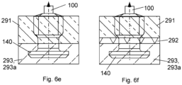
- the stud holes 250 may e.g. penetrate into the underlayer 293 through the tread cap layer 291 and, optionally, through an intermediate layer 292.
- a stud hole (and the stud 100) penetrates into the underlayer 293 through the tread cap layer 291.
- a stud hole (and the stud 100) penetrates into the underlayer 293 through the tread cap layer 291 and an intermediate layer 292.
- Figs. 6a stud hole (and the stud 100) penetrates into the underlayer 293 through the tread cap layer 291 and an intermediate layer 292.
- each stud 100 there is a lamella-free area around each stud 100 so that the radius of the lamella-free area is more than 6 mm, preferably about 8 mm. In accordance with an embodiment of the invention, the radius is about 10 mm.
Landscapes
- Engineering & Computer Science (AREA)
- Mechanical Engineering (AREA)
- Tires In General (AREA)
Description
- The invention relates to studded tyres. The invention relates to studded pneumatic tyres. The invention relates to studded pneumatic tyres for passenger car vehicles.
- Functions of a tyre on an automotive vehicle include providing sufficient traction for accelerating, driving, and braking; and providing adequate steering control particularly at high speeds. Traction is commonly referred to as grip and steering control as handling. Grip is affected also by the ground (e.g. a road surface) on which the tyre is commonly used. Winter tyres, which are intended for icy and snowy (wintry) roads, are commonly equipped with studs to improve grip on ice. However, studs of the studded tyres wear during use and the grip may become worse compared to new, unused studded tyres.
- The patent application
US 2015/0375572 A1 discloses a pneumatic tyre, which includes land portions partitioned and formed by inclined grooves inclined with respect to a tyre circumferential direction. Stud pins are embedded in at least one of the land portions. The number of embedded stud pins embedded in a shoulder region is from 1.5 to 2.5 times the number of embedded stud pins embedded in a centre region. A protruding amount of the stud pins in the shoulder region is from 1.2 to 2.0 times the protruding amount of the stud pins in the centre region. - The international patent application
WO 2022030610 A1 discloses a stud pin and a tyre comprising said stud pin. A stud pin includes a body embedded into the tread of a tyre, a tip that projects out from the leading end of the body, and a flange disposed on the base end of the body, wherein a groove is formed in the surface on the leading end of the tip, and the total area Sx of the tip and the area Sy of the groove when viewed in the direction of the central axis of the body satisfies the relationship 0.20 ≤ Sy / Sx ≤ 0.50. - An aim of the present invention is to provide a studded tyre which provides for good grip within a reasonable lifetime of the tyre. In other words, the grip of the studded tyre is maintained at a good level also when the tyre has been in use for a long time.
- According to a first aspect of the invention, a studded tyre is presented, comprising a tread having a plurality of tread blocks, a plurality of studs installed in at least some of the tread blocks, wherein studs at a centre area have higher protrusion from the surface of the tread block than studs in a shoulder area of the tyre.
- The tread blocks may be arranged in a periodic fashion called as a pitch. In other words, similar sequence of such a group of tread blocks of one pitch may be repeated over the whole circumference of the tyre. In other words, each pitch includes a predetermined geometry of whole and/or partial tread blocks. The number of tread blocks in each pitch may vary in width across the tire. There may be several different pitches, with variable dimensions or geometry.
- In accordance with an embodiment of the invention, the configuration of the studs is such that the protrusion of studs in the centre area is in a range from 0.8 mm to 1.6 mm, preferably 0.9 mm to 1.4 mm, most preferably 1.0 mm to 1.3 mm and the protrusion of studs in the shoulder areas is in a range from 0.6 mm to 1.3 mm, preferably 0.6 mm to 1.2 mm, most preferably 0.6 mm to 0.9 mm so that the studs at the centre area have higher protrusion than studs in the shoulder area.
- According to an example of the invention, the protrusion of a majority of the studs in the centre area of the tyre is in the range from 1.0 to 1.3 mm and the protrusion of a majority of the studs in the shoulder area of the tyre is in the range from 0.8 to 1.0 so that the protrusion of the studs in the centre area are 0.2 or at least 0.1 mm higher than the protrusion of the studs in the shoulder area. According to another example, the average protrusion of the studs in the centre area of the tyre is in the range from 1.0 to 1.3 mm and the average protrusion of the studs in the shoulder area of the tyre is in the range from 0.8 to 1.0 so that the protrusion of the studs in the centre area are 0.2 or at least 0.1 mm higher than the protrusion of the studs in the shoulder area. According to yet another example, the protrusion of studs in the centre area is in the range from 1.1 to 1.2 mm and the protrusion of studs in the shoulder areas is in the range from 0.9 to 1.0 mm. According to still another example, the protrusion of studs in the centre area is in the range from 0.9 to 1.0 mm and the protrusion of studs in the shoulder areas is in the range from 0.8 to 1.0 mm so that the protrusion of the studs in the centre area are 0.2 or at least 0.1 mm higher than the protrusion of the studs in the shoulder area.
- In accordance with an embodiment of the invention, the higher protrusion in the centre area is achieved by using in a centre area studs in which a pin of the stud is longer than in studs in the shoulder area.
- In accordance with an embodiment of the invention, the higher protrusion in the centre area is achieved by using similar studs in both centre area and shoulder areas but using stud holes having different depths in the centre area than in the shoulder areas.
- In accordance with an embodiment of the invention, the higher protrusion in the centre area is achieved by using longer studs in the centre area than studs in the shoulder area, although the pin of each stud may have substantially equal length.
- Several embodiments of the invention are defined in the dependent claims.
- Within this description the term tyre refers to a tyre configured to be used on a wheel of a car, especially a passenger car. In line with this, within this description, a road wear of the studded tyre is defined as the road wear in the test specified in the standard SFS7503:2022:en, which concerns primarily tyres designed for vehicles in categories M1 and N1, as defined in the Consolidated Resolution on the Construction of Vehicles (R.E.3), document ECE/TRANS/WP.29/78/Rev.4, para. 2. These categories are:
- M1: Vehicles used for the carriage of passengers and comprising not more than eight seats in addition to the driver's seat,
- N1: Vehicles used for the carriage of goods and having a maximum mass not exceeding 3.5 tonnes.
- The standard SFS7503:2022:en specifies the test procedure in detail. On the general level, in the test, a vehicle equipped with the tyres to be tested is driven over test specimens (i.e. test stones) with specified speed for a specific number of times. The test requires that two identical tyres are tested simultaneously; they are used on one side of the vehicle in the test. According to the standard, a properly loaded vehicle is driven two-hundred times over the test stones at the speed of 100 km/h. As both the front and rear wheel pass the test stones, there are a total of four hundred passes of the test tyres over the test stones; and these passes cause the test stones to wear. Road wear according to the standard SFS7503:2022:en is the average weight loss of three test stone rows compensated by the weight loss of reference stones, if applicable. For further details refence is made to the standard. The average wear of test specimens is expressed in units of mass (i.e. in grams). The less the tyres wear the specimens, the less is the result (grams, g) of the test, and thus the less the tyres wear a regular road, too.
- In the following the invention will be explained in more detail with reference to the appended drawings, in which
- Fig. 1a
- shows a stud in a side view,
- Fig. 1b
- shows a cross-section Ib of a pin of the stud of
Fig. 1a , the cross-section Ib indicated inFig. 1a , - Fig. 1c
- shows a cross-section Ic of a upper flange of the stud of
Fig. 1a , the cross-section Ic indicated inFig. 1a , - Fig. 1d
- shows a cross-section Id of a waist of the stud of
Fig. 1a , the cross-section Id indicated inFig. 1a , - Fig. 1e
- shows a cross-section Ie of a bottom flange of the stud of
Fig. 1a , the cross-section Ie indicated inFig. 1a , - Fig. 1f
- shows the stud in a side view and further measures thereof,
- Fig. 1g
- shows a pin of a stud and an upper flange of a first type in a top view,
- Fig. 1h
- shows a pin of a stud and an upper flange of a second type in a top view,
- Fig. 1i
- shows a stud for a centre area of a tyre in a side view,
- Fig. 1j
- shows a stud for a shoulder area of a tyre in a side view,
- Fig. 2a
- shows a tyre in a perspective view,
- Fig. 2b
- shows schematically a circumference of a tyre in a side view,
- Fig. 2c
- shows a part of a tyre in a perspective view,
- Fig. 2d
- shows a half of a cross-section of a tyre with some measures,
- Fig. 2e
- shows a part of a tread of a tyre,
- Fig. 3a
- shows a quarter of a cross-section of a tyre,
- Fig. 3b
- shows a part of a tread provided with sipes, grooves, and studs,
- Fig. 3c
- shows the detail IIIa of
Fig. 3b , - Fig. 3d
- shows the detail IIIb of
Fig. 3c , - Fig. 4a
- illustrates a land portion of a tyre,
- Fig. 4b
- illustrates a sea portion of a tyre,
- Fig. 5
- shows schematically tread blocks, a groove, a sipe and a stud,
- Fig. 6a
- shows schematically a stud arranged on an underlayer and penetrating through a cap,
- Fig. 6b
- shows schematically a stud arranged on an underlayer and penetrating through an intermediate layer and a cap layer,
- Fig. 6c
- shows schematically a stud arranged on an underlayer and a stud pad,
- Fig. 6d
- shows schematically a stud arranged on an underlayer and a stud pad,
- Fig. 6e
- shows schematically a stud arranged in an underlayer without a stud pad,
- Fig. 6f
- shows schematically a stud arranged in an underlayer without a stud pad,
- Fig. 7
- shows a part of a tread of a tyre,
- Fig. 8a
- shows a cross section of a part of a tyre according to an embodiment; and
- Fig. 8b
- shows a cross section of a part of a tyre according to another embodiment.
-
Figure 2a shows astudded tyre 200. Astudded tyre 200 comprises atread 210 andmultiple studs 100 provided in thetread 210. Referring toFig. 2c , thestuds 100 have been installed into stud holes 250. The stud holes 250 may be made to thetread 210 during vulcanization of the tyre. Thestudded tyre 200 is a tubeless tyre, i.e. functional on a rim and without an inner tyre. - Referring to
Figs. 2c and 2e , thetread 210 of thestudded tyre 200 comprises tread blocks 220 such thatgrooves 230 are arranged between the tread blocks 220. In this description, a "rib" is considered as alarge tread block 221 in the middle of thetyre 200 which can be regarded as a plurality of mutually connected tread blocks. For example, the tread ofFigs. 2c and 2e include acentral tread block 221 that extends over the entire circumference of the tread, even if such a tread block could be called a central rib. Atread 210 needs not comprise a tread block that extends circumferentially throughout thetread 210. In addition, thetyre 200 comprisesstuds 100, which have been installed into at least some of the tread blocks 220. Referring toFig. 1a , astud 100 preferably comprises apin 110, and preferably eachstud 100 of thetyre 200 comprises apin 100. Moreover, in thetyre 200, at least thepins 110 of thestuds 100 are exposed on the tread 210 (see e.g.Fig. 3a and5 ). Thepins 110 are exposed so that studs have a protrusion P100 of astud 100 measured from thetread 210. The protrusion P100 is indicated inFig. 5 . The protrusion P100 is measured in the radial direction +SR and from a planar surface defined by the radially outermost edges of thestud hole 250 into which thestud 100 has been installed. Naturally, thetread 210 itself defines the edges of thestud hole 250. - Some measures of a
tyre 200 are depicted inFig. 2d . Within this description, the width W200 of thetyre 200, as shown inFig. 2d , refers to the "Section Width" as defined in the Standards Manual 2023 of the European Tyre and Rim Technical Organization (ETRTO). The height H200 of thetyre 200 is also shown inFig. 2d , and is defined as the "Section Height" in the ETRTO Standards Manual 2023. Correspondingly, the Section Width, i.e. the width W200 of thetyre 200 as defined herein (and in the ETRTO standards manual) is the linear distance between the outsides of the sidewalls of an inflated tyre excluding elevations due to labelling (markings), decoration, or protective bands or ribs.Figure 2d also shows half of a cross section of arim 300 onto which thetyre 200 has been installed. - In practice, the tyre width W200 is related to the size marking shown on the
tyre 200. In general, the size marking is shown on a tyre as w/hRr, wherein w denotes a width, h an aspect ratio and r a radius. According to the ETRTO standards manual, typical size markings refer to Design Width (i.e. the width W200 of the tyre 200) and an overall diameter as shown in the Table 1 below:Table 1: Tyre width and diameter indicated by a size marking of a tyre Size Section Overall Size Section Overall Size Section Overall Width Diameter Width Diameter Width Diameter (mm) (mm) (mm) (mm) (mm) (mm) 145/55R16 150 566 205/55R15 214 607 255/55R16 265 686 155/55R14 162 526 205/55816 214 632 255/55R17 265 712 155/55R16 162 576 205/55R17 214 658 255/55R18 265 737 165/55R14 170 538 205/55R18 214 683 255/55R19 265 763 165/55R15 170 563 205/55R19 214 709 255/55R20 265 788 175/55R15 182 573 215/55R16 226 642 255/55R21 265 813 175/55R16 182 598 215/55R17 226 668 265/55R18 277 749 175/55R17 182 624 215/55R18 226 693 265/55R19 277 775 175/55R18 182 649 215/55R19 226 719 265/55R20 277 800 175/55R20 182 700 225/55R16 233 654 275/55R15 284 683 185/55R14 195 560 225/55R17 233 680 275/55R16 284 708 185/55R15 195 585 225/55R18 233 705 275/55R17 284 734 185/55R16 195 610 225/55R19 233 731 275/55R18 284 759 195/55R15 201 595 235/55R16 245 664 275/55R19 284 785 195/55R16 201 620 235/55R17 245 690 275/55R20 284 810 195/55R17 201 646 235/55R18 245 715 275/55R21 284 835 195/55R18 201 671 235/55R19 245 741 285/55R18 297 771 195/55R19 201 697 235/55R20 245 766 285/55R19 297 797 195/55R20 201 722 245/55R16 253 676 305/55R20 316 855 195/55R21 201 747 245/55R17 253 702 325/55R22 336 917 245/55R18 253 727 245/55R19 253 753 - It is noted that Table 1 shows only some examples. A tyre may have a different size, in particular another aspect ratio than 55, such as 40, 45, 60 or 65.
-
Fig. 1a shows an example of astud 100 which can be used with thestudded tyre 200. It should be noted that this is only an example and also other kinds of studs may be used. Moreover, thetyre 200 may comprise more than one kind of studs. - The direction Sz of
Fig. 1a is a longitudinal direction of the stud, and the stud may be installed to thetread 210 such that the positive longitudinal direction +Sz is the radially outward direction +SR of the tyre (see e.g.Fig. 5 ). A purpose of thestud 100 is to improve grip of thetyre 200 particularly on ice. - Referring to
Fig. 1a , thestud 100 comprises abody 120 and apin 110. Thebody 120 comprises abottom flange 140 and asecond part 130. Thesecond part 130 is joined to thebottom flange 140 and extends in the longitudinal direction Sz of thestud 100 from thebottom flange 140. Thepin 110 protrudes from thesecond part 130 in the longitudinal direction Sz of thestud 100. Thepin 110 comprises hard metal or ceramic. In terms of Vickers hardness, the Vickers hardness of thepin 110 is higher than the Vickers hardness of thesecond part 130. - As shown in
Fig. 1e , thebottom flange 140 has a first cross-section on a plane (i) that has a normal in the longitudinal direction Sz of the stud, the first cross-section having a first area A140. Typically, as shown inFig. 1e , thebottom flange 140 has the first cross-section on a plane that has a normal in the longitudinal direction Sz of the stud. Moreover, thebottom flange 140 has a profile shape extending at least a certain distance in the direction of the normal of the first cross-section.Fig. 1e shows the cross-section Ie of thebottom flange 140 of the stud ofFig. 1a , the cross-section Ie indicated inFig. 1a . In such a case, thesecond part 130 extends straight. However, thesecond part 130 may extend in a curvilinear fashion.Fig. 1d shows the cross-section Id of thebottom flange 140 of the stud ofFig. 1a , the cross-section Id indicated inFig. 1a . Also in that case, thesecond part 130 extends straight. However, thesecond part 130 may extend in a curvilinear fashion. - The
pin 110 has a second cross-section on a plane that has a normal in the longitudinal direction Sz of thestud 100, the second cross-section having a second area A110.Fig. 1b shows the cross-section Ib of thepin 110 of the stud ofFig. 1a , the cross-section Ib indicated inFig. 1a . The first area A140 is greater than the second area A110. - To provide a good grip, the
pin 110 should protrude fromsecond part 130 sufficiently. A first height H110 which is the height that thepin 110 protrudes from the second part 130 (e.g. from anupper flange 134 of the second part 130) is depicted inFigs. 1f ,1i and 1j . As shown inFigs. 1f ,1i and 1j , thesecond part 130 extends in the longitudinal direction Sz of thestud 100 from thebottom flange 140 to aninterfacial point 112 between thesecond part 130 and thepin 110 and does not extend further in this direction. InFig. 1a , awaist 132 and theupper flange 134 constitute thesecond part 130. - The
pin 110 and thesecond part 130 define the first height H110, which is the length thepin 110 protrudes from theinterfacial point 112 in the longitudinal direction Sz to theextremal point 114 of thepin 110 in the longitudinal direction Sz of the stud. Thus, thepin 110 protrudes the first height H110 from thesecond part 130 of the stud; particularly from theinterfacial point 112. - For good grip, the first height H110 should be sufficient. However, if the first height H110 is excessive, the road wear caused by the stud may increase. Moreover, not only the
tip 110 affects grip and road wear. Particularly, a size of thebottom flange 140 affects grip and road wear, too. Alarge bottom flange 140 oftentimes implies that thestud 100 is arranged in thestud hole 250 in a stiff manner, i.e. thebottom flange 140 resists movement of the studs in the negative radial direction -SR when the stud is pressed in this direction. A reason is that thelarge bottom flange 140 supports thestud 100 to the rubber material of the tyre beneath the bottom flange in a sturdy manner. This typically results in a high piercing force of the stud on the road; and a high piercing force implies high road wear. This applies also vice versa. A small bottom flange will, in general, reduce the piercing force and in this way the road wear. - The piercing force herein refers to the piercing force as defined in the regulation "Ajoneuvon nastarenkaiden tekniset vaatimukset ja tyyppihyväksyntä" TRAFICOM/220809/03.04.03.00/2019 of the Ministry of Transport and Communications on studs of tyres for vehicles (dated 10.2.2021). This Ministry is the Ministry of Transport and Communications of Finland.
- It has been found that a good compromise between the piercing force and the road wear is achieved when a ratio A140/H110 of the first area A140 to the first height H110 is 20 to 50 mm2/mm. An even more preferable value for this ratio A140/H110 is 25 to 48 mm2/mm, most preferably 28 to 45 mm2/mm.
- In accordance with an embodiment of the invention, the shape of all the studs is substantially similar to each other, but some of the measures of the studs are different so that height H110 of the
pin 114 is longer in at least most of thestuds 100 in the centre area CR than most of thestuds 100 in the shoulder areas SR1, SR2.Fig. 1i illustrates as a side view an example of astud 100 for the centre area CR andFig. 1j illustrates as a side view an example of astud 100 for the shoulder areas SR1, SR2. It can be seen that the height H110 of thepin 114 of thestud 100 ofFig. 1i is longer than the height H110 of thepin 114 of thestud 100 ofFig. 1j . -
Fig. 8a shows a cross section of a part of atyre 200 according to an embodiment of the invention in which thestuds 100b ofFig. 1i have been used in the centre area CR and thestuds 100a ofFig. 1j have been used in the shoulder areas SR1, SR2. It can be seen that the depth of stud holes 250b in the centre area CR and in the shoulder areas SR1, SR2 is substantially equal. - In accordance with an embodiment of the invention, the higher protrusion is achieved by using similar stud lengths in both centre area and shoulder areas but using stud holes having different depths in the centre area than in the shoulder areas. This is illustrated in
Fig. 8b , which shows a cross section of a part of the tyre 2++ according to this embodiment. It can be seen that the depth of the stud holes 250b in the centre area CR is smaller than the depth of thestud holes 250a in the shoulder areas SR1, SR2. - It should be noted that the cross sections of
Figs. 8a and 8b are only showing principles of these two embodiments but the scales and all the details of these figures may not correspond to practical implementations. For example, thetread 210 is not showing different layers whichtyres 200 typically have. - In accordance with yet another embodiment of the invention, the higher protrusion is achieved by using in the centre area CR studs which have longer total length H100 than studs in the shoulder area SR1, SR2, but the
pin 110 of each stud may have substantially equal length H110. Hence, the length H120 (Fig. 1f ) of thebody 120 of thestud 100 is longer in the studs of the centre area than in the studs of the shoulder area SR1, SR2. -
Studs 100 in the centre area CR tend to wear faster thanstuds 100 in the shoulder areas SR1, SR2. Therefore, having the higher protrusion in the studs 10 of the centre area CR may prolong the good grip of thetyre 200. Furthermore, the studs in the shoulder areas SR1, SR2 tend to rise upwards during usage of thetyre 200, wherein the grip in the shoulder areas SR1, SR2 may also tend to last longer. Overall, these two factors may make it possible to use thestudder tyres 200 according to the invention longer than without utilization of the present inventive idea. - The low value of road wear may be achieved e.g. by having a sufficiently low dynamic impact to the road, particularly when driving at the speed indicated in the road wear standard. Features affecting the dynamic impact of the studs to the road include:
- Mass of the stud,
- Protrusion P100 of the stud,
- Area of the bottom flange 140 (A140),
- Size and shape of the
stud pin 110, and - The rubber material supporting the
bottom flange 140, the material optionally being comprised by anunderlayer 293. - Both the first area A140 and the rubber material supporting the
bottom flange 140 have effect on how sturdy the stud is supported to the rubber material of the tire. - As for the material of the
tyre 200, also the rubber material of thetread 210 may affect road wear induced by thestuds 100 of thetyre 200. Thus, in an embodiment of the invention, thetread 210 comprises rubber material having a Shore hardness in the range 48 to 59 Sh(A) as measured with durometer type A, at the temperature 23 °C. In an embodiment of the invention, thetread 210, in particular the part of the tyre that is configured to contact a road in use, is formed of rubber material having a Shore hardness in the range 48 to 59 Sh(A) as measured with durometer type A, at the temperature 23 °C. - The stiffness of the tread blocks 220 can also be softened by providing
sipes 240 to thetread 210. Thus, in an embodiment of the invention, at least some of the tread blocks 220 are provided withsipes 240. As is well known,sipes 240 are narrow openings in tread blocks 220.Sipes 240 are shown inFigs. 3b and3c . Concerning the narrowness of the sipes, in an embodiment of the invention, a width W240 of all thesipes 240 is less than 2.0 mm. The width W240 of a sipe is shown inFig. 3d . In an embodiment of the invention, a depth D240 (Fig. 5 ) of all thesipes 240 is at least 2.0 mm. A bottom a sipe needs not be even. In such a case the depth of thesipe 240 refers to a depth of the deepest point of thesipe 240. - The tread blocks 220 of the
tread 210 also limitgrooves 230. Thus, thetread 210 comprises tread blocks 220 such thatgrooves 230 are arranged between the tread blocks 220. As an example,Fig. 3d shows agroove 230 arranged between afirst tread block 220a and asecond tread block 220b. In an embodiment of the invention, a width W230 of at least one of thegrooves 230, as measured on the level of thetread 210 limiting thegroove 230, is more than 4.0 mm. The width W230 is shown inFig. 3d . The grooves may taper radially inward (i.e. in the -SR direction). Thus, in an embodiment of the invention, a width W230 of at least one of thegrooves 230 decreases in an inward radial direction -SR of the tyre. Reference is made toFig. 5 . In an embodiment of the invention, a depth D230 of at least one of thegrooves 230 is more than 7.0 mm, preferably 8 mm to 15 mm. A depth of asipe 240 is less than a depth of agroove 230. More specifically, in an embodiment of the invention, a depth D240 of all thesipes 240 is less than a depth D230 of one of thegrooves 230. - When the
tyre 200 comprises sipes, preferably, nosipe 240 is provided close to astud hole 250, in which astud 100 has been installed. Referring toFig. 3d , astud 100 has been installed in astud hole 250, and no part of any of thesipes 240 is arranged closer than the distance DSS to a centre of thestud hole 250. The distance DSS may be in a range from 6 mm to 12 mm, for example. Preferably, no part of any of thesipes 240 is arranged closer than 8 mm or closer than 10 mm to a centre of thestud hole 250. In addition or alternatively, multiple studs have been installed in multiple stud holes and no part of any of thesipes 240 is arranged closer than 6 mm, 8 mm, 10 mm, 11 mm or 12 mm to a centre of any one of the stud holes 250. In addition or alternatively, multiple studs have been installed in multiple stud holes and no part of any of thesipes 240 is arranged closer than 6 to 10 mm to a centre of any one of the stud holes 250.Fig. 3d shows the distance DSS that is arranged between asipe 240 and a centre of astud hole 250. This has the effect thatstud 100 is reliably fixed to itsstud hole 250. Otherwise thesipe 240 would soften the tread also near thestud hole 250 and in this way increase the risk of thestud 100 falling from thestud hole 250. Thus, this also improves the grip of thetyre 200. - In an embodiment of the invention, at least some of the
grooves 230 are inclined such that they define a V-shape or a half of a V-shape, the V-shape or the half thereof defining a direction of rotation R of thetyre 200 when used driving forwards, the direction of rotation R being reverse to the direction to which the V-shape or the half thereof opens. As an example, the grooves ofFig. 2c define a half of a V-shape. In contrast the grooves ofFig. 3d define a full V-shape. Such a tread is what is commonly known as "unidirectional" i.e. the tyre is designed to be fitted to the vehicle wheel in one particular way. This improves the grip of the tyre by improving the efficiency of draining water and/or slush from underneath thetyre 200 in regular use of the tyre. This arrangement of grooves also does not increase the road wear. Such a unidirectional tyre may comprise a marking on a sidewall of the tyre, the marking being indicative of the direction of rotation for the tyre. - Such a tyre can be manufactured by vulcanizing a green tyre to form the
tyre 200 and forming stud holes to thetread 210 of thetyre 200 during the vulcanizing the green tyre. After vulcanization, thestuds 100 are installed to the stud holes 250 of thetread 210.Figure 3b shows twostud holes 250 to which a stud has not been installed. As shown therein, typically the stud holes 250, before thestuds 100 have been inserted into theholes 250, are small compared to thestuds 100. However, because the tread blocks 220 are elastic, the stud holes 250 are stretched when installing thestuds 100 to theholes 250. This further improves fixing of thestuds 100 to the stud holes 250. - When the tyre comprises
sipes 240, in an embodiment of the invention, the sipes are formed to thetread 210 of thetyre 200 during the vulcanizing the green tyre by using lamella blades. - As detailed above both (i) the area of the cross section of the
pin 110 and (ii) a stiffness of the support of thebottom flange 140 affect the dynamic impact. Thus, as an example, the tyre according to the invention may comprise astud 100 comprising thebottom flange 140, thesecond part 130, and thepin 110 such that the greatest diameter of thebottom flange 140 is in the range from 7.5 mm to 10.5 mm and the smallest diameter of thebottom flange 140 is in the range from 5.0 mm to 9.5 mm. - The cross-section of the
bottom flange 140 is preferably greater than a cross-section of thesecond part 130. Thus, thebottom flange 140 anchors thestud 100 well to thestud hole 250. Therefore, in an embodiment of the invention, thesecond part 130 has a third cross-section on a plane that has a normal in the longitudinal direction Sz of thestud 100, the third cross-section having a third area (A130, A132, A134), and the first area A140 is greater than the third area (A130, A132, A134). The third area A130 may correspond to a (sole) third area of the second part; or the third area A130 may correspond to an area A132 of a cross-section of awaist 132 or an area A134 of a cross-section of aupper flange 134. - As detailed above, the protrusion P100 of a
stud 100 affects the dynamic impact. Preferably, the protrusion P100 is between 0.6 mm and 2.0 mm, more preferably between 0.7 mm and 1.6 mm, and most preferably between 0.8 mm and 1.4 mm measured from an inflated unused tyre. The protrusion of stud P100 is shown inFig. 5 . In an embodiment of the invention, these values apply to an average of the protrusions P100 of the studs 100 (i.e. all the studs 100) of the tyre. In an embodiment of the invention, these values apply to all the protrusions P100 of the studs 100 (i.e. all the studs 100) of the tyre individually. However, it should be noted that, due to the inventive idea presented in this specification, the average of protrusions is bigger in the centre area CR than in the shoulder areas SR1, SR2. - In an embodiment of the invention the
tyre 200 comprisesmultiple studs 100 comprising only pins 110 having one type of cross section. Thus, in an embodiment of the invention, thepin 110 of all the studs of thetyre 200 are identical in shape. - In another embodiment of the invention the
tyre 200 comprises more than one type of stud pins 110. In other words, some studs have pins of one type of cross section and some other studs have pins of another type of cross section. There may also be a third, fourth etc. types of cross sections of thepins 110 at different locations of thestuds 100 of thetyre 200. - In yet another embodiment of the invention the
tyre 200 comprises more than one type ofstuds 100. In other words, some studs have one type of cross section at different locations and some other studs have another type of cross section at those locations. There may also be a third, fourth etc. types of cross sections at different locations of thestuds 100 of thetyre 200. - To this end, in an embodiment of the invention the
tyre 200 comprisesmultiple studs 100a of a first stud type andmultiple studs 100b of a second stud type.Fig. 3b shows atread 210 to whichmultiple studs 100a of a first stud type andmultiple studs 100b of a second stud type have been installed. For example, the shape of thestuds 100a of the first type are shown inFig. 1g , and the shape of thestuds 100b of the second type are shown inFig. 1h . AlsoFig. 2e shows atread 210 to whichmultiple studs 100a of a first stud type andmultiple studs 100b of a second stud type have been installed. - In
Fig. 2e , a central region CR of the tread comprisesstuds 100b of the second stud type, and both a first shoulder region SR1 and a second shoulder region SR2 comprisestuds 100a of the first stud type.Studs 100b of the second type are not identical with thestuds 100a of the first stud type. Thus, in an embodiment of the invention, a central region CR of thetread 210 is arranged between a first shoulder region SR1 of thetread 210 and a second shoulder region SR2 of thetread 210. The central region CR comprises a circumferential central line CL of thetread 210. In an embodiment of the invention, the circumferential central line CL of thetread 210 divides also the central region to two equally wide parts. The first shoulder region SR1 extends in an axial direction SAX from a first side S1 of thetread 210 towards the circumferential central line CL. The first side S1 is shown inFig. 2e . The second shoulder region SR2 extends in an axial direction SAX from a second side S2 of thetread 210 towards the circumferential central line CL. The second side S2 is also shown inFig. 2e . In an embodiment of the invention, the first shoulder region SR1, the second shoulder region SR2 and the central region CR constitute thetread 210. In other words, in the embodiment of the invention, thetread 210 consists of the first shoulder region SR1, the second shoulder region SR2 and the central region CR. - In accordance with an embodiment of the invention, the central region CR has a width which is in a range from 33 % to 49 % of the total width W210 of the
tread 210, but may be different from that. Some examples to be mentioned are the range from 35 % to 40 %, or 44 % to 48 % - The tread blocks 220 of the
tyre 200 define a land portion LP of thetread 210. A part of the land portion LP of the tread is shown by black colour inFig. 4a . Naturally, the land portion extends around the whole circumference of thetread 210. The land portion of thetread 210 consists of the parts of the tread blocks 220 that are arranged to contact a surface (e.g. the road) in use of thetyre 200. The land portion has a total land area A220 (as measured e.g. in units of dm2). Some of the tread blocks 220 of thetyre 200 have been provided with studs, and also the cross-sections of thestuds 100 belong to the land portion LP. - An area of the
tread 210 which is simultaneously contacting a surface may be called as a footprint. The area of the footprint may slightly vary due to certain conditions. For example, the load affected to each tyre and the pressure within the tyres may affect the area of the footprint. The more load the larger may be the area of the footprint. On the other hand, the higher the pressure the smaller the footprint may be. - The tread blocks 220 of the
tyre 200 define an envelope surface. The envelope surface consists of the land portion LP of thetread 210 and the regions defined by the openings of thegrooves 230. The openings of thegrooves 230 may be commonly referred to as a sea portion SP of the envelope surface, as shown in black colour inFig. 4b . Also the sea portion SP extends around the whole circumference of thetread 210. The sea portion SP of the envelope surface has a sea area A230. The land portion LP (Fig. 4a ) and the sea portion SP (Fig. 4b ) together form the envelope surface. Thus, the tread blocks 220 are delimited outward in the radial direction +SR by the envelope surface; and the land portion of the envelope surface forms the ground contact surface of thetread 210. The envelope surface has a total envelope area A210, as measured e.g. in units of dm2. - Thus, the total envelope area A210 is the sum of the land area A220 and the sea area A230, i.e. A210=A220+A230. Referring to
Figs. 2a and 2b , a width of thetread 210 is depicted by W210 and a circumference by C210. The total envelope area A210 is thus approximately equal to the product W210×C210. However, because thetread 210 is also curved in the axial direction SAX on thetyre 200, this is only an approximation. As for the circumference C210, the circumference C210 may equal pi (i.e. 3.14) times the overall diameter indicated in Table 1. - In this description, an average land ratio refers to the ratio of the total land area A220 to the total envelope area A210. In other words, by the land ratio is meant the ratio of the ground contacting surface area of tread blocks to the imaginary ground contacting area of the tread, the imaginary ground contacting area of the tread including spaces (i.e. grooves) between adjacent blocks and the blocks themselves. In other words, by the land ratio is meant the ratio of the ground contacting surface area of tread blocks to a ground contacting area of an imaginary tread, the imaginary tread having been formed from the tread by filling the grooves with tread material.
- In the art, one sometimes uses the term sea area ratio to mean the ratio of the sea area to the imaginary ground contacting area of the tread. In line with these definitions the sum of the land ratio and the sea area ratio equals one.
- In the art, the term "land-to-sea ratio" may, occasionally, be used interchangeably with the land ratio as defined above. However, the term land-to-sea ratio or land/sea ratio may relate to a ratio of the land area (ground contacting area) to the sea area (non-contacting area) of the tread. To avoid possible confusion, the term land area is used throughout this description and in the meaning defined above.
- According to an embodiment of the invention, the land ratio of the tread is greater in a central area than in a shoulder area.
Figs. 3a and 3b therefore show a circumferential central line CL of thetread 210. The circumferential central line CL divides thetread 210 to two equally wide parts. The circumferential central line CL is an intersection of thetread 210 and its equatorial plane EP. As shown inFig. 3b , a central region CR of thetread 210 is arranged between a first shoulder region SR1 of thetread 210 and a second shoulder region SR2 of thetread 210. The central region CR comprises the circumferential central line CL of thetread 210. In an embodiment of the invention, the circumferential central line CL of thetread 210 divides also the central region to two equally wide parts. Limits between these regions are shown by dash lines inFigs. 3a and 3b . The circumferential central line CL is also shown by a dash line. In an embodiment of the invention, the first shoulder region SR1, the second shoulder region SR2 and the central region CR constitute thetread 210. In other words, in the embodiment of the invention, thetread 210 consists of the first shoulder region SR1, the second shoulder region SR2 and the central region CR. - In an embodiment of the invention, at least two thirds of the
studs 100 that are arranged in the central region CR are of the second stud type (they arestuds 100b), and at least two third of the studs arranged in the first and second shoulder regions SR1, SR2 are of the first stud type (they arestuds 100a). - In an embodiment of the invention, the
studs 100a of the first stud type comprise substantially identical first pins. A cross-section of a first pin, the plane of the cross-section having a normal to the longitudinal direction Sz of the stud, has a first shape. Moreover, thestuds 100b of the second stud type comprise substantially identical second pins. A cross-section of a second pin, the plane of the cross-section having a normal to the longitudinal direction Sz of the stud, has a second shape. The second shape is different from the first shape. For example, thepin 110 of thestud 100a of the first type is shown inFig. 1g , and thepin 110 of thestud 100b of the second type, is shown inFig. 1h . - In an embodiment of the invention, not only the stud pins 110 of the first stud type are different from the stud pins of the second type, but also at least some parts of the
body 130 of thestuds 100a of the first stud type are different from corresponding parts of thebody 130 of thestuds 100b of the second stud type. - By using at least two different types of studs, the grip of the tyre can be optimized. This is particularly true, when studs of the second type are used in the central region CR, and studs of the first type are used in the shoulder regions SR1, SR2.
- The grip of the tyre can be improved by using sufficiently many studs. The grip of the tyre can be improved by using sufficiently many studs on both sides of the circumferential central line CL.
- Concerning the former, in an embodiment of the invention, the
tread 210 has the first width W210 and the first circumference C210, as defined above. Moreover, thetread 210 is provided with a total number N100 ofstuds 100. A ratio (N100/(W210×CL)) of the total number of the studs N100 to the width of the tread W210 and the circumference C210 of the tread can be equal to or more than 5.6 pieces per square-decimetre (pcs/dm2). In an embodiment of the invention, the ratio (N100/(W210×C210)) of the total number N100 of the studs to the product W210×C210 of the first width W210 and the first circumference C210 is more than 6.8 pieces per square-decimetre (pcs/dm2). - In another embodiment of the invention, a ratio (N100/(W210×C210)) of the total number N100 of the studs to the product W210×C210 of the first width W210 and the first circumference C210 is more than 7.2 pieces per square-decimetre (pcs/dm2). The first circumference C210 may be measured along the circumferential central line CL, e.g. along a circumferential central line of the envelope surface of the
tread 210. - Thus, in an embodiment of the invention, N100/(W210×C210CL) ≥ 5.6 pcs/dm2, wherein N100 is a total number of studs in the tire, W210 is the width of the tread (dm), and C210 is the circumference of the
tyre 200 in dm, measured along the circumferential central line CL. - In the other embodiment of the invention mentioned above, N100/(W210×C210CL) > 6.8 pcs/dm2.
- In the third embodiment of the invention mentioned above, N100/(W210×C210CL) > 7.2 pcs/dm2.
- Concerning the latter (the number of studs on each half of the tread), in an embodiment of the invention, the circumferential central line CL of the tread 210 (as well as the equatorial plane EP) defines a first half of the
tread 210 and a second half of the tread 210 (seeFig. 7 ). In the embodiment of the invention, the first half comprises a first number N1 ofstuds studs - The width W210 of the
tread 210 may be somewhat smaller than a width W200 of the tyre. Within this description, the width W200 of thetyre 200, as shown inFig. 2d , refers to the "Section Width" as defined in the ETRTO standards manual 2023. The height H200 of thetyre 200 is also shown inFig. 2d , and is defined as the "Section Height" in the ETRTO standards manual 2023. Correspondingly, the Section Width, i.e. the width W200 of thetyre 200 as defined herein (and in the ETRTO standards manual) is the linear distance between the outsides of the sidewalls of an inflated tyre excluding elevations doe to labelling (markings), decoration, or protective bands or ribs.Figure 2d also shows half of a cross section of arim 300 onto which thetyre 200 has been installed. As for the circumference C210, the circumference C210 may equal pi (i.e. 3.14) times the overall diameter indicated in Table 1 (see above). - The first width W210 (i.e. that of the tread) may be equal to the reference tread width as defined in the ETRTO standards manual 2023 (see Design Guide, Page PC.7). In accordance with the definitions therein, the reference tread width C is calculatable as

- Herein s is the Section Width (defined above), i.e. the width W200 of the tyre, and ar is the nominal aspect ratio, which is readable from the size marking w/hRr (see above), the "h" indicating the aspect ratio. Thus, the first width W210 of the
tread 210 may equal the value C as calculatable with the equation given above, wherein s equals W200. - The following Table 2 shows some examples of measures of tyres. The size indicates the diameter and width of the tyre, the aspect ratio indicates the height of the tyre as a percentage of the width of the tyre, ETRTO design width is the width of the tyre according to ETRTO, the reference tread width is the actual width of the tread.
Table 2: Some measures of typical tyres Size Aspect Ratio (AR) ETRTO design width Reference tread width (RTW) 275/35R20 35 278 251.6 255/40R19 40 260 228.8 235/45R18 45 236 201.7 225/50R17 50 233 193.3 205/55R16 55 214 172.1 185/60R15 60 189 147.2 175/65R14 65 177 133.4 - Referring to
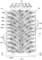
Fig. 7 , each stud is arranged at a distance from the circumferential central line CL. Thus, each stud defines a circumferential row rij, the circumferential row being parallel to the circumferential central line CL and at such a distance that the stud is arranged on the circumferential row rij. Herein "rij" stands for j:th circumferential row in the i:th half. Fig 4c shows nine rows (j=1, 2, ..., 9) on both halves (i=1 or 2). Several studs may be arranged on the same circumferential row. However, preferably not all the studs of first half of the tread are arranged on the same circumferential row. This applies also for the studs of the second half of the tread. Preferably, studs are arranged on at least six different circumferential rows. - Referring to
Fig. 7 , in an embodiment of the invention, each one of themultiple studs tyre 200 is arranged on a circumferential row (r11, r12, r13, r14, r15, r16, r17, r18, r19, r21, r22, r23, r24, r25, r26, r27, r28, r29) such that thestuds - Preferably, the circumferential central line CL of the
tread 210 defines the first half of thetread 210 and the second half of thetread 210, and the studs are arranged such that at least three different circumferential rows (r11, r12, r13, r14, r15, r16, r17, r18, r19) of the at least six different circumferential rows (r11, r12, r13, r14, r15, r16, r17, r18, r19, r21, r22, r23, r24, r25, r26, r27, r28, r29) are arranged on the first half, and at least three different circumferential rows (r21, r22, r23, r24, r25, r26, r27, r28, r29) of the at least six different circumferential rows (r11, r12, r13, r14, r15, r16, r17, r18, r19, r21, r22, r23, r24, r25, r26, r27, r28, r29) are arranged on the second half. - Having such many rows rij effective spreads the studs to the
tread 210 reasonably evenly, thereby improving the grip. - In addition to the
tread 210 of thetyre 200, the structure of thetyre 200 provides for sufficient stiffness of thetyre 200 and thereby also affect the grip and road wear properties of thetyre 200. Thetread 210 is provided as an outermost layer of a carcass of thestudded tyre 200. A quarter of a cross-section of atyre 200 is shown inFig. 3a . The relevant cross-section for Fig. 5e is such a cross-section that is a cross-section of thetyre 200 with a plane that comprises the axis of rotation of the tyre, which is parallel to the axial direction SAX (seeFig. 2e ) and located in the centre defined by thetyre 200. Such cross-section has two parts, which are substantially identical. One of such parts is shown inFig. 3a . A half of only one of the parts is shown inFig. 3a . An equatorial plane EP (shown inFig. 3a ) of thetyre 200 divides the tyre to two equally large parts. The circumferential central line CL defined above is arranged in the equatorial plane EP. - As detailed above, the tyre comprises the tread blocks 220 that define the
grooves 230 and thetread 210, which is an outermost layer of the carcass. Preferably, the carcass of thestudded tyre 200 comprises one or more layers of reinforcing textile or textiles and one of more reinforcing metal layers. - In general, a
tyre 200 has side surfaces on opposite sides of thetread 210. The side surfaces connect the bead area of the tyre to thetread 210. The side surfaces may have various markings indicating the tire size, tire speed class, tire purpose (winter/summer), tire manufacturer and/or tire name. The bead area of a tyre has a cable. The function of the cable and the bead area is to fit thetire 200 to the rim. - The
tyre 200, in particular the carcass thereof, comprises afirst ply 288. The ply/plies 288 may comprise fibrous material, e.g. Kevlar, polyamide, carbon fibres, polyester or glass fibres. In an embodiment of the invention, the tire further comprises a second ply. In this embodiment, the second ply may also comprise fibrous material. - The carcass further comprises a
first metal belt 287. Preferably, the carcass further comprises atextile belt 284, such as atextile belt 284 comprising fibrous polyamide (e.g. Nylon, aramid, or Cordura). Preferably, the carcass further comprises the second ply and asecond metal belt 286. The metal belt(s) 287, 286 is/are resilient metal belts, such as steel belts comprising wires. - The tread blocks 220 are formed in a
cap layer 291 of thetyre 200. Thecap layer 291 may further comprise material connecting the tread blocks 220 to thecap layer 291 and layers beneath thecap layer 291. Under the tread blocks 220 of thetread 210, i.e. under thecap layer 291, the tyre preferably comprises anunderlayer 293 made of suitable rubber material. A purpose of theunderlayer 293 is to adaptively affect the impact of the studs to the road according to temperature. Thus, at higher temperatures (e.g. above 0°C) the impact of the studs may be lower than at lower temperatures, e.g. below 0°C. - Hence, road wear due to the
studs 100 of thetyre 200 may be lower when roads are not covered by show and/or ice. Thus, in an embodiment of the invention, thebottom flange 140 of at least a part of thestuds 100 of thetyre 200 are arranged partly in theunderlayer 293. - The
underlayer 293 may have a hardness which may vary substantially with the ambient temperature, wherein the wear of the road surface may be reduced. Theunderlayer 293 is preferably arranged at least partly below the anti-skid stud. Thus, the bottom of the anti-skid stud can be in contact with theunderlayer 293, and the anti-skid stud can be pressed against and/or retract into theunderlayer 293. - The
anti-skid stud 100, preferably thebottom flange 140 of the anti-skid stud, can be in direct contact with theunderlayer 293. Thus, in this embodiment of the invention, there is no other material layer between theanti-skid stud 100 and theunderlayer 293. Alternatively, for example, aseparate stud pad 199 may be arranged between theanti-skid stud 100 and theunderlayer 293. - Further, the
studded tyre 200 may comprise a separate bottom rubber ply (also called as an undertread) arranged below theunderlayer 293. Thus, the properties of thestudded tyre 200 can be improved. Moreover, the process of manufacture of thetyre 200 can be easier to control. In an example, thestudded tyre 200 is not provided with a bottom rubber ply below theunderlayer 293. Thus, the manufacturing costs of thetyre 200 can be reduced. - As depicted in
Figs. 6a to 6d , preferably thestuds 100 are arranged to contact theunderlayer 293 directly or viastud pads 199. The stud holes 250 may e.g. penetrate into theunderlayer 293 through thetread cap layer 291 and, optionally, through anintermediate layer 292. As an example, inFig. 6a , a stud hole (and the stud 100) penetrates into theunderlayer 293 through thetread cap layer 291. As an example, inFig. 6b , a stud hole (and the stud 100) penetrates into theunderlayer 293 through thetread cap layer 291 and anintermediate layer 292. As indicated inFigs. 6c and 6d , astud pad 199 may be arranged in between theunderlayer 199 and thebottom flange 140 of thestud 100. Thebottom flange 140 of at least a part of thestuds 100 of thetyre 200 are arranged at least partly on theunderlayer 293. -
Fig. 6e illustrates an example in which thebottom flange 140 and a part of thewaist 132 are embedded in theunderlayer 293 in a tyre which does not have theintermediate layer 292.Fig. 6f illustrates an example in which thebottom flange 140 and a part of thewaist 132 are embedded in theunderlayer 293 in a tyre which has theintermediate layer 292 above theunderlayer 293. In this example theintermediate layer 292 and also a part of theunderlayer 293 surrounds thewaist 132 but theintermediate layer 292 can also be higher at the height of theupper flange 291, for example. -
Figure 6a shows a detailed view of the cap layer (as indicated by the tread block 220) and aunderlayer 293. As detailed therein, thebottom flange 140 is in contact with theunderlayer 293. Therefore, the material of theunderlayer 293, in connection with the first area A140 define a degree of support the carcass of thetyre 200 imposes on thestud 100. Support is needed particularly at low temperatures so that the protrusion ofstuds 100 from the surface of thetreads 220 will not become too low when the studs are in contact with the road surface. At temperatures when no ice or snow should not exist on the road surface the adaptive underlayer becomes softer wherein the protrusion ofstuds 100 from the surface of thetreads 220 may become lower and thus may wear road surface less than if theunderlayer 293 were not adaptive. A reasonably soft material of the cap layer and the treads provides for good grip on ice and snow. - For these reasons, in an embodiment of the invention, at an ambient temperature of -30°C a Shore (A) hardness of the
underlayer 293 is not less than a Shore (A) hardness of the material of the tread blocks 220. The mechanical properties of theunderlayer 293 need not depend on temperature; whereby this difference in the Shore hardnesses may apply also at higher temperatures. - However, preferably, the material of the
underlayer 293, which supports thebottom flange 140, is selected such that it softens at higher temperatures. In other words, the hardness of the material of theunderlayer 293 under eachstud 100 decreases when temperature of the material increases (i.e. the hardness has a negative temperature coefficient). This has the effect that even if the studs are highly supported at low temperatures (because of the shore hardness, see above), at higher temperatures the studs do not wear the road as much, because of the reduced support provided by thesofter underlayer 293. - Therefore, in an embodiment of the invention, the
underlayer 293 comprises adaptive material. The adaptive material is adaptive to the temperature in the sense that it hardens at low temperatures and softens at high temperatures. Thus, the underlayer according to this specification can also be called as an adaptive underlayer. The underlayer may consist primarily or entirely of the adaptive material layer. The adaptive material layer comprises a material having a hardness substantially depending on ambient temperature. - The adaptive material layer can be made of a material compound having a hardness substantially depending on ambient temperature. Preferably, the underlayer is made of an elastomer material having a hardness depending on the temperature of the elastomer material.
- The materials for the underlayer and the intermediate layer can be selected so that a dynamic stiffness of the underlayer differs from a dynamic stiffness of the intermediate layer at most temperatures.
- The dynamic stiffness of the underlayer, determined at a temperature of 20°C, can be configured to be less than 25 MPa, preferably from 5 to 20 MPa. Further, the dynamic stiffness of the intermediate layer, determined at a temperature of 20°C, can be configured to be at least 25 MPa, preferably at least 27 MPa, and more preferably from 30 to 100 MPa. Technical effect is to decrease road wear while the intermediate layer supports the whole tire and the studs of the tire at the warmer temperature.
- The dynamic stiffness of the underlayer, determined at a temperature of 0°C, can be configured to be at least two times the dynamic stiffness of the underlayer at a temperature of 20°C. Further, the dynamic stiffness of the intermediate layer, determined at a temperature of 0°C, can be configured to be from 1 to 1.5 times, preferably from 1.1 to 1.4 times, the dynamic stiffness of the intermediate layer at a temperature of 20°C. Technical effect is that the winter grip properties of the winter tire can be substantially improved while the intermediate layer supports the whole tire and the studs of the tire at warmer temperatures.
- The dynamic stiffness of the underlayer can be at least 100% higher, preferably at least 150% higher than the dynamic stiffness of the intermediate layer at a temperature of 0°C. Technical effect is that the ice grip properties of the winter tire can be substantially improved at 0°C. The dynamic stiffness of the underlayer may further be equal to or less than 1000 % higher, such as equal to or less than 900% higher, preferably equal to or less than 580% higher than the dynamic stiffness of the intermediate layer at a temperature of 0°C.
- Furthermore, the dynamic stiffness of the intermediate layer can be higher than the dynamic stiffness of the underlayer at a temperature of at least 5 °C, such as at a temperature of at least 7 °C. In a particularly advantageous embodiments of the invention, the dynamic stiffness of the intermediate layer is higher than the dynamic stiffness of the underlayer at temperatures from 10 °C to 20 °C. Technical effect is to reduce road wear while improving handling properties of the tire. Further technical effect is that the intermediate layer effectively supports the stud.
- The dynamic stiffness of the underlayer at -25°C can be at least 20 times the dynamic stiffness of the underlayer at +20°C. Thus, the grip properties of the winter tire can be substantially improved, and, for example, the braking distance needed by the winter tire under certain conditions can be substantially reduced.
- The dynamic stiffness E* of the
underlayer 293 can be - ∘ lower than 25 MPa at an ambient temperature of +20°C,
- ∘ between 25 and 500 MPa, preferably from 40 to 400 MPa, at an ambient temperature of 0°C, and
- ∘ at least 500 MPa at an ambient temperature of -30°C.
- The change in the dynamic stiffness of the underlayer upon a decrease in the temperature can have a greater impact on the grip of the tire in winter than the change in the hardness of the material upon a decrease in the temperature. For the above-mentioned dynamic stiffness values, the adjustment of the stud's dynamic impact of the tire at different temperatures can be more controllable, and the grip properties of the winter tire can be better optimized for different temperatures. Thanks to the above-mentioned dynamic stiffness, for example the braking distance on an icy road can be substantially reduced.
- In a preferred example, for optimizing the grip properties of the tire in winter,
- (A) the hardness (ShA) of the underlayer can be
- lower than 60 ShA and preferably lower than 55 ShA at 20°C,
- preferably at least 60 ShA, more preferably at least 65 ShA, at 0°C, and
- higher than 75 ShA at -30°C;
and furthermore,
- (B) the dynamic stiffness of the underlayer can be
- lower than 25 MPa at an ambient temperature of 20°C,
- between 25 and 500 MPa at an ambient temperature of 0°C, and
- at least 500 MPa at an ambient temperature of -30°C.
- In general, the higher the dynamic stiffness E*, the harder the material. These values have been found suitable for providing sufficient grip at low temperatures, yet low road wear at high temperatures. In this specification, the term dynamic stiffness E* refers to the stiffness of the material as determined according to the standard ASTM D5992-96 (reapproved 2018).
- The temperature dependence of dynamic stiffness E* can be affected by selecting the tan delta peak temperature of the material in a suitable manner. The
underlayer 293 can comprise, primarily comprise, or consist of a material whose tan delta peak temperature can be at least -20°C, for example at least -15°C, preferably at least -12°C, more preferably at least -10°C, or at least - 8°C, and most preferably at least -5°C. Furthermore, the tan delta peak temperature of said material may not be higher than 20°C, for example not higher than 15°C, preferably not higher than 12°C, more preferably not higher than 10°C, or not higher than 8°C, and most preferably not higher than 5°C. Thus, the hardening of the underlayer can be suitable in view of road wear and winter grip. The closer to 0°C the tan delta peak temperature of the material is arranged, the more accurately the hardening of the underlayer can take place at a point optimal in view of road wear and winter grip, and the easier the impact of the stud can be to control at different temperatures. - Therefore, in an embodiment of the invention, the
underlayer 293 is made of a material having a tan delta peak temperature that is between -20°C and +12°C, and more preferably between -5°C and +5°C. - The term "tan delta" refers to tan δ and the term "tan delta peak" refers to the temperature associated to the turning point of tan delta curve and tan delta maximum value.
- The dynamic stiffness E* also affects the hardness of the material. In an embodiment of the invention, a Shore A hardness of the
underlayer 293 can be configured to be in a range between 45 ShA and 65 ShA at an ambient temperature of +22°C, more preferably at least 65 ShA, at 0°C, and at least 75 ShA at an ambient temperature of -30°C. More preferably, a Shore A hardness of theunderlayer 293 is between 45 ShA and 60 ShA, most preferably in a range between 45 ShA and 55 ShA at an ambient temperature of +22°C, and higher than 75 ShA at an ambient temperature of -30°C. - Furthermore, the dynamic stiffness of the underlayer can be lower than 20 MPa at an ambient temperature of 20°C, between 40 and 400 MPa at an ambient temperature of 0°C, and at least 500 MPa at an ambient temperature of -30°C.
- In this specification, the term Dynamic stiffness (E*) refers to the stiffness of the material which can be determined according to the standard ASTM D5992-96 (reapproved 2018).
- The mechanical properties as well as their temperature dependence can be adapted by material selections.
- The underlayer can comprise one or more polymer materials having a hardness depending on the temperature of the respective polymer material. The underlayer can comprise elastomer material.
- In addition to the material of the
underlayer 293 as such, also the thickness thereof affects the support of thestud 100. - Advantageously, the thermally adaptive underlayer has a thickness in a direction Sz substantially perpendicular to the direction of rotation of the tyre, wherein the thickness d1 is in the range of 0.5 mm to 8 mm, preferably in the range of 1 mm to 7.5 mm, most preferably in the range of 1.5 mm to 7 mm. Thus, the properties of the underlayer can be easier to control so that the underlayer can yield to a particularly suitable extent when the ambient temperature rises, which can further reduce wear of the road surface. In this application, the thickness of the underlayer refers to the thickness of the underlayer when the anti-skid stud is in a rest position, that is, when the anti-skid stud is not subjected to external forces, such as pressure caused by the driving surface.
- Referring to
Fig. 3a , the material layer that is adjacent to theunderlayer 293 and radially inward from underlayer may be thelayer 284, i.e. a textile belt. This thickness applies particularly to the thickness of the adaptive material. - Other features of the
stud 100 that are particularly related to the amount of road wear include the following, each one separately or in combination:
Preferably, a total length of thestud 100 is more than 9.5 mm, advantageously in the range from 10.0 mm to 11.0 mm. - In accordance with an embodiment of the invention, the density of the
studs 100 in thetread 210 is more than or equal to 5.6 studs / dm2, preferably more than 6.8 studs / dm2, and more preferably more than 7.2 studs / dm2. - In accordance with an embodiment of the invention, the studs are arranged in three or more rows in the direction of rotation at both sides of the centre line CL. In other words, there are at least six rows of studs.
- In accordance with an embodiment of the invention, the number of
studs 100 on each side of thetyre 200 is the same or a difference of the number ofstuds 100 on each side of thetyre 200 is not higher than 10%. - In accordance with an embodiment of the invention, there is a lamella-free area around each
stud 100 so that the radius of the lamella-free area is more than 6 mm, preferably about 8 mm. In accordance with an embodiment of the invention, the radius is about 10 mm. - In accordance with an embodiment of the invention, the
studs 100 of thetyre 200 have one, two or three axes of symmetry. - In addition to the above mentioned properties related to the studs, properties of the
tyre 200 may also affect the noise generated by thetyre 200 during driving. - In accordance with an embodiment of the invention, there is a base layer beneath the
studs 100. The base layer may also be called as anunderlayer 293. - In accordance with an embodiment of the invention, there is a layer of material under each
stud 100 which is softer than the intermediate layer at least when the temperature of the tyre is higher than 10°C. - In accordance with an embodiment of the invention, there is an
intermediate layer 292 around eachstud 100. - In accordance with an embodiment of the invention, there is a
stud pad 199 under eachstud 100. - In accordance with an embodiment of the invention, the
tyre 200 comprises one kind ofstuds 100. - In accordance with an embodiment of the invention, the
tyre 200 comprises at least two different kinds ofstuds 100. - In accordance with an embodiment of the invention, the tread blocks 220 are arranged to groups of over 50 pitch on both sides of the
tread 210. - In accordance with an embodiment of the invention, stud holes 250 have been formed to the tread during vulcanization of the
tyre 200. - In accordance with an embodiment of the invention, the
tread 210 of thetyre 200 comprises a mixture of two or more layers.
Claims (18)
- A tyre (200) comprising- a tread (210) having tread blocks (220);- a plurality of stud holes (250, 250a, 250b); and- a plurality of studs (100) installed in at least some of the stud holes (250),
characterized in that- studs (100b) in a centre area (CR) of the tyre (200) have higher protrusion from a surface of the tread blocks (220) than studs (100a) in a shoulder area (SR1, SR2) of the tyre (200). - The tyre (200) according to claim 1 characterized by one of the following:- the protrusion of a majority of the studs (100b) in the centre area (CR) of the tyre (200) is in the range from 1.0 to 1.3 mm and the protrusion of a majority of the studs (100a) in the shoulder area (SR1, SR2) of the tyre (200) is in the range from 0.8 to 1.0 so that the protrusion of the studs (100b) in the centre area (CR) are 0.2 or at least 0.1 mm higher than the protrusion of the studs (100a) in the shoulder area (SR1, SR2).
- The tyre (200) according to claim 1 characterized by one of the following:- the average protrusion of the studs (100b) in the centre area (CR) of the tyre (200) is in the range from 1.0 to 1.3 mm and the average protrusion of the studs (100a) in the shoulder area (SR1, SR2) of the tyre (200) is in the range from 0.8 to 1.0 so that the protrusion of the studs (100b) in the centre area (CR) are 0.2 or at least 0.1 mm higher than the protrusion of the studs (100a) in the shoulder area (SR1, SR2).
- The tyre (200) according to claim 1, 2 or 3 characterized by one of the following:- the protrusion of the studs (100b) in the centre area (CR) of the tyre (200) is in the range from 1.1 to 1.2 mm and the protrusion of the studs (100a) in the shoulder area (SR1, SR2) of the tyre (200) is in the range from 0.9 to 1.0 mm, or- the protrusion of the studs (100b) in the centre area (CR) of the tyre (200) is in the range from 0.9 to 1.1 mm and the protrusion of the studs (100a) in the shoulder area (SR1, SR2) of the tyre (200) is in the range from 0.8 to 1.0 mm so that the protrusion of the studs (100b) in the centre area (CR) are 0.2 or at least 0.1 mm higher than the protrusion of the studs (100a) in the shoulder area (SR1, SR2).
- The tyre (200) according to any one of the claims 1 to 4 comprising grooves (230) arranged between the tread blocks (220), wherein depth of the grooves (230) is greater than 7.0 mm, advantageously between 8.0 mm and 15.0 mm.
- The tyre (200) according to any one of the claims 1 to 5, wherein the tyre (200) comprises at least two different kinds of studs (100).
- The tyre (200) according to any one of the claims 1 to 6, wherein a total length of the stud (100) is more than 9.5 mm, advantageously in the range from 10.0 mm to 11.0 mm.
- The tyre (200) according to any one of the claims 1 to 7, wherein the studs (100) comprise a bottom flange (140) such that a greatest diameter of the bottom flange (140) is in the range from 7.5 mm to 10.5 mm and a smallest diameter of the bottom flange (140) is in the range from 5.0 mm to 9.5 mm.
- The tyre (200) according to any one of the claims 1 to 8, wherein density of the studs (100) in the tread (210) is more than or equal to 5.6 studs / dm2, preferably more than 6.8 studs / dm2, and more preferably more than 7.2 studs / dm2.
- The tyre (200) according to any one of the claims 1 to 9 comprising studs in three or more rows in the direction of rotation at both sides of a centre line (CL).
- The tyre (200) according to any one of the claims 1 to 10, wherein studs (100b) in the centre area (CR) have longer pin (110) than studs (100a) in the shoulder area (SR1, SR2).
- The tyre (200) according to any one of the claims 1 to 10, wherein a length of a body (120) of the studs (100b) in the centre area (CR) is different from a length of a body (120) of the studs (100a) in the shoulder area (SR1, SR2).
- The tyre (200) according to any one of the claims 1 to 11, wherein stud holes (250a) in the shoulder area (SR1, SR2) are deeper than stud holes (250b) in the centre area (CR).
- The tyre (200) according to any one of the claims 1 to 13, wherein the number of studs (100) at both sides of a centre line (CL) is the same or a difference of the number of studs 100 at both sides of a centre line (CL) is less or equal to 10%.
- The tyre (200) according to any one of the claims 1 to 14, the tread comprising a mixture of two or more layers (291, 292, 293).
- The tyre (200) according to claim 13, wherein the hardness of the layer of material under each stud (100) decreases when temperature of the material increases.
- The tyre (200) according to any one of the claims 1 to 16, wherein the stud holes (250) have been formed to the tread (210) during vulcanization of the tyre (200).
- The tyre (200) according to any one of the claims 1 to 17, wherein the studs (100) comprise- a body (120) comprising a bottom flange (140) and a second part (130), a cross-section of the bottom flange (140) having a first area (A140); and- a pin (119) protruding a first height (H110) from the second part (130),wherein the ratio of the first area (A140) to the first height (H110) is in the range 20 to 50 mm2/mm, wherein the properties of the tyre (200) are such that a result of a road wear test according to SFS7503:2022:en is less than 1.00 g.
Priority Applications (4)
| Application Number | Priority Date | Filing Date | Title |
|---|---|---|---|
| EP23172086.3A EP4461571B1 (en) | 2023-05-08 | 2023-05-08 | A studded tyre for vehicles |
| FIEP23172086.3T FI4461571T3 (en) | 2023-05-08 | 2023-05-08 | Studded tire for vehicles |
| CA3235925A CA3235925A1 (en) | 2023-05-08 | 2024-04-19 | A studded tyre for vehicles |
| US18/654,183 US12515481B2 (en) | 2023-05-08 | 2024-05-03 | Studded tyre for vehicles |
Applications Claiming Priority (1)
| Application Number | Priority Date | Filing Date | Title |
|---|---|---|---|
| EP23172086.3A EP4461571B1 (en) | 2023-05-08 | 2023-05-08 | A studded tyre for vehicles |
Publications (2)
| Publication Number | Publication Date |
|---|---|
| EP4461571A1 EP4461571A1 (en) | 2024-11-13 |
| EP4461571B1 true EP4461571B1 (en) | 2025-07-09 |
Family
ID=86330654
Family Applications (1)
| Application Number | Title | Priority Date | Filing Date |
|---|---|---|---|
| EP23172086.3A Active EP4461571B1 (en) | 2023-05-08 | 2023-05-08 | A studded tyre for vehicles |
Country Status (4)
| Country | Link |
|---|---|
| US (1) | US12515481B2 (en) |
| EP (1) | EP4461571B1 (en) |
| CA (1) | CA3235925A1 (en) |
| FI (1) | FI4461571T3 (en) |
Family Cites Families (11)
| Publication number | Priority date | Publication date | Assignee | Title |
|---|---|---|---|---|
| JP3057381B2 (en) * | 1991-04-11 | 2000-06-26 | 横浜ゴム株式会社 | Pneumatic radial tires for passenger cars |
| JP2009166806A (en) * | 2008-01-21 | 2009-07-30 | Toyo Tire & Rubber Co Ltd | Pneumatic stud tire and pneumatic tire for stud tire |
| RU2492064C2 (en) * | 2009-02-24 | 2013-09-10 | Бриджстоун Корпорейшн | Snow tire |
| JP2014151811A (en) * | 2013-02-12 | 2014-08-25 | Yokohama Rubber Co Ltd:The | Pneumatic tire |
| JP6100127B2 (en) * | 2013-08-20 | 2017-03-22 | 東洋ゴム工業株式会社 | Pneumatic tire |
| FI127185B (en) * | 2016-06-27 | 2017-12-29 | Nokian Renkaat Oyj | Procedure for dubbing tires for vehicles and double tires for vehicles |
| FR3053002B1 (en) * | 2016-06-28 | 2019-07-05 | Compagnie Generale Des Etablissements Michelin | PNEUMATIC CLOUTE |
| DE102016221854A1 (en) * | 2016-11-08 | 2018-05-09 | Continental Reifen Deutschland Gmbh | vehicle tires |
| FI127522B (en) * | 2017-02-06 | 2018-08-15 | Nokian Renkaat Oyj | A device for studding a tire |
| US20200324579A1 (en) * | 2019-04-09 | 2020-10-15 | The Goodyear Tire & Rubber Company | Winter tire stud arrangement |
| FI131346B1 (en) * | 2020-08-06 | 2025-03-04 | Yokohama Rubber Co Ltd | Stud and tire including the same |
-
2023
- 2023-05-08 FI FIEP23172086.3T patent/FI4461571T3/en active
- 2023-05-08 EP EP23172086.3A patent/EP4461571B1/en active Active
-
2024
- 2024-04-19 CA CA3235925A patent/CA3235925A1/en active Pending
- 2024-05-03 US US18/654,183 patent/US12515481B2/en active Active
Also Published As
| Publication number | Publication date |
|---|---|
| CA3235925A1 (en) | 2025-06-17 |
| US20240375453A1 (en) | 2024-11-14 |
| FI4461571T3 (en) | 2025-09-18 |
| EP4461571A1 (en) | 2024-11-13 |
| US12515481B2 (en) | 2026-01-06 |
Similar Documents
| Publication | Publication Date | Title |
|---|---|---|
| US6719025B2 (en) | Dual composition tread band for tire | |
| EP1140527B1 (en) | Dual composition tread band for tire | |
| FI85673B (en) | FORDONSDAECK. | |
| EP0205233B1 (en) | Pneumatic tyre | |
| US8047243B2 (en) | Replacement tread for a truck racing tire | |
| EP1440822A1 (en) | Pneumatic tire | |
| EP0827845A1 (en) | Tire having tread portion with two different rubbers to control irregular wear | |
| US20200307319A1 (en) | Low noise tire tread | |
| EP0934835A2 (en) | Heavy duty radial tyre | |
| EP3666556B1 (en) | Pneumatic tyre | |
| PL196122B1 (en) | Light weight fiberglass belted radial tire | |
| CN111511582A (en) | Heavy cargo vehicle tires with improved durability | |
| US20130014870A1 (en) | Tread for a pneumatic tire | |
| EP3659824B1 (en) | Pneumatic tire | |
| EP3753752A1 (en) | Pneumatic tire | |
| US20200198406A1 (en) | Tread for a pneumatic tire | |
| EP4461571B1 (en) | A studded tyre for vehicles | |
| EP4461570B1 (en) | A studded tyre for vehicles | |
| US20240424837A1 (en) | Tire and tire tread | |
| US5343919A (en) | Pneumatic radial tire with specified belt curvature | |
| EP3536523B1 (en) | Tire with evolving tread | |
| JPH0781326A (en) | Ice and snow road tires | |
| CN113677544A (en) | Tires for agricultural vehicles including improved tread | |
| JP4202513B2 (en) | Heavy duty tire | |
| JP7172954B2 (en) | pneumatic tire |
Legal Events
| Date | Code | Title | Description |
|---|---|---|---|
| PUAI | Public reference made under article 153(3) epc to a published international application that has entered the european phase |
Free format text: ORIGINAL CODE: 0009012 |
|
| STAA | Information on the status of an ep patent application or granted ep patent |
Free format text: STATUS: REQUEST FOR EXAMINATION WAS MADE |
|
| 17P | Request for examination filed |
Effective date: 20240112 |
|
| AK | Designated contracting states |
Kind code of ref document: A1 Designated state(s): AL AT BE BG CH CY CZ DE DK EE ES FI FR GB GR HR HU IE IS IT LI LT LU LV MC ME MK MT NL NO PL PT RO RS SE SI SK SM TR |
|
| GRAP | Despatch of communication of intention to grant a patent |
Free format text: ORIGINAL CODE: EPIDOSNIGR1 |
|
| STAA | Information on the status of an ep patent application or granted ep patent |
Free format text: STATUS: GRANT OF PATENT IS INTENDED |
|
| INTG | Intention to grant announced |
Effective date: 20250409 |
|
| GRAS | Grant fee paid |
Free format text: ORIGINAL CODE: EPIDOSNIGR3 |
|
| GRAA | (expected) grant |
Free format text: ORIGINAL CODE: 0009210 |
|
| STAA | Information on the status of an ep patent application or granted ep patent |
Free format text: STATUS: THE PATENT HAS BEEN GRANTED |
|
| AK | Designated contracting states |
Kind code of ref document: B1 Designated state(s): AL AT BE BG CH CY CZ DE DK EE ES FI FR GB GR HR HU IE IS IT LI LT LU LV MC ME MK MT NL NO PL PT RO RS SE SI SK SM TR |
|
| REG | Reference to a national code |
Ref country code: GB Ref legal event code: FG4D |
|
| REG | Reference to a national code |
Ref country code: CH Ref legal event code: EP |
|
| P01 | Opt-out of the competence of the unified patent court (upc) registered |
Free format text: CASE NUMBER: APP_29766/2025 Effective date: 20250623 |
|
| REG | Reference to a national code |
Ref country code: IE Ref legal event code: FG4D |
|
| REG | Reference to a national code |
Ref country code: DE Ref legal event code: R096 Ref document number: 602023004633 Country of ref document: DE |
|
| REG | Reference to a national code |
Ref country code: FI Ref legal event code: FGE |
|
| REG | Reference to a national code |
Ref country code: SE Ref legal event code: TRGR |
|
| REG | Reference to a national code |
Ref country code: NL Ref legal event code: MP Effective date: 20250709 |
|
| PG25 | Lapsed in a contracting state [announced via postgrant information from national office to epo] |
Ref country code: PT Free format text: LAPSE BECAUSE OF FAILURE TO SUBMIT A TRANSLATION OF THE DESCRIPTION OR TO PAY THE FEE WITHIN THE PRESCRIBED TIME-LIMIT Effective date: 20251110 |
|
| PG25 | Lapsed in a contracting state [announced via postgrant information from national office to epo] |
Ref country code: NL Free format text: LAPSE BECAUSE OF FAILURE TO SUBMIT A TRANSLATION OF THE DESCRIPTION OR TO PAY THE FEE WITHIN THE PRESCRIBED TIME-LIMIT Effective date: 20250709 |
|
| REG | Reference to a national code |
Ref country code: AT Ref legal event code: MK05 Ref document number: 1811540 Country of ref document: AT Kind code of ref document: T Effective date: 20250709 |
|
| PG25 | Lapsed in a contracting state [announced via postgrant information from national office to epo] |
Ref country code: IS Free format text: LAPSE BECAUSE OF FAILURE TO SUBMIT A TRANSLATION OF THE DESCRIPTION OR TO PAY THE FEE WITHIN THE PRESCRIBED TIME-LIMIT Effective date: 20251109 |
|
| PG25 | Lapsed in a contracting state [announced via postgrant information from national office to epo] |
Ref country code: NO Free format text: LAPSE BECAUSE OF FAILURE TO SUBMIT A TRANSLATION OF THE DESCRIPTION OR TO PAY THE FEE WITHIN THE PRESCRIBED TIME-LIMIT Effective date: 20251009 |
|
| REG | Reference to a national code |
Ref country code: LT Ref legal event code: MG9D |
|
| PG25 | Lapsed in a contracting state [announced via postgrant information from national office to epo] |
Ref country code: AT Free format text: LAPSE BECAUSE OF FAILURE TO SUBMIT A TRANSLATION OF THE DESCRIPTION OR TO PAY THE FEE WITHIN THE PRESCRIBED TIME-LIMIT Effective date: 20250709 |
|
| PG25 | Lapsed in a contracting state [announced via postgrant information from national office to epo] |
Ref country code: HR Free format text: LAPSE BECAUSE OF FAILURE TO SUBMIT A TRANSLATION OF THE DESCRIPTION OR TO PAY THE FEE WITHIN THE PRESCRIBED TIME-LIMIT Effective date: 20250709 |
|
| PG25 | Lapsed in a contracting state [announced via postgrant information from national office to epo] |
Ref country code: GR Free format text: LAPSE BECAUSE OF FAILURE TO SUBMIT A TRANSLATION OF THE DESCRIPTION OR TO PAY THE FEE WITHIN THE PRESCRIBED TIME-LIMIT Effective date: 20251010 |
|
| PG25 | Lapsed in a contracting state [announced via postgrant information from national office to epo] |
Ref country code: LV Free format text: LAPSE BECAUSE OF FAILURE TO SUBMIT A TRANSLATION OF THE DESCRIPTION OR TO PAY THE FEE WITHIN THE PRESCRIBED TIME-LIMIT Effective date: 20250709 |
|
| PG25 | Lapsed in a contracting state [announced via postgrant information from national office to epo] |
Ref country code: BG Free format text: LAPSE BECAUSE OF FAILURE TO SUBMIT A TRANSLATION OF THE DESCRIPTION OR TO PAY THE FEE WITHIN THE PRESCRIBED TIME-LIMIT Effective date: 20250709 Ref country code: PL Free format text: LAPSE BECAUSE OF FAILURE TO SUBMIT A TRANSLATION OF THE DESCRIPTION OR TO PAY THE FEE WITHIN THE PRESCRIBED TIME-LIMIT Effective date: 20250709 |
|
| PG25 | Lapsed in a contracting state [announced via postgrant information from national office to epo] |
Ref country code: RS Free format text: LAPSE BECAUSE OF FAILURE TO SUBMIT A TRANSLATION OF THE DESCRIPTION OR TO PAY THE FEE WITHIN THE PRESCRIBED TIME-LIMIT Effective date: 20251009 |
|
| PG25 | Lapsed in a contracting state [announced via postgrant information from national office to epo] |
Ref country code: ES Free format text: LAPSE BECAUSE OF FAILURE TO SUBMIT A TRANSLATION OF THE DESCRIPTION OR TO PAY THE FEE WITHIN THE PRESCRIBED TIME-LIMIT Effective date: 20250709 |
|
| PG25 | Lapsed in a contracting state [announced via postgrant information from national office to epo] |
Ref country code: SM Free format text: LAPSE BECAUSE OF FAILURE TO SUBMIT A TRANSLATION OF THE DESCRIPTION OR TO PAY THE FEE WITHIN THE PRESCRIBED TIME-LIMIT Effective date: 20250709 |
|
| PG25 | Lapsed in a contracting state [announced via postgrant information from national office to epo] |
Ref country code: DK Free format text: LAPSE BECAUSE OF FAILURE TO SUBMIT A TRANSLATION OF THE DESCRIPTION OR TO PAY THE FEE WITHIN THE PRESCRIBED TIME-LIMIT Effective date: 20250709 |
|
| PG25 | Lapsed in a contracting state [announced via postgrant information from national office to epo] |
Ref country code: IT Free format text: LAPSE BECAUSE OF FAILURE TO SUBMIT A TRANSLATION OF THE DESCRIPTION OR TO PAY THE FEE WITHIN THE PRESCRIBED TIME-LIMIT Effective date: 20250709 |
|
| PG25 | Lapsed in a contracting state [announced via postgrant information from national office to epo] |
Ref country code: CZ Free format text: LAPSE BECAUSE OF FAILURE TO SUBMIT A TRANSLATION OF THE DESCRIPTION OR TO PAY THE FEE WITHIN THE PRESCRIBED TIME-LIMIT Effective date: 20250709 |
|
| PG25 | Lapsed in a contracting state [announced via postgrant information from national office to epo] |
Ref country code: SK Free format text: LAPSE BECAUSE OF FAILURE TO SUBMIT A TRANSLATION OF THE DESCRIPTION OR TO PAY THE FEE WITHIN THE PRESCRIBED TIME-LIMIT Effective date: 20250709 Ref country code: EE Free format text: LAPSE BECAUSE OF FAILURE TO SUBMIT A TRANSLATION OF THE DESCRIPTION OR TO PAY THE FEE WITHIN THE PRESCRIBED TIME-LIMIT Effective date: 20250709 |