EP4461557A1 - Writing instrument refill and method for marking writing instrument refill - Google Patents
Writing instrument refill and method for marking writing instrument refill Download PDFInfo
- Publication number
- EP4461557A1 EP4461557A1 EP23737311.3A EP23737311A EP4461557A1 EP 4461557 A1 EP4461557 A1 EP 4461557A1 EP 23737311 A EP23737311 A EP 23737311A EP 4461557 A1 EP4461557 A1 EP 4461557A1
- Authority
- EP
- European Patent Office
- Prior art keywords
- storage tube
- ink storage
- writing implement
- ink
- engraved mark
- Prior art date
- Legal status (The legal status is an assumption and is not a legal conclusion. Google has not performed a legal analysis and makes no representation as to the accuracy of the status listed.)
- Pending
Links
Images



Classifications
-
- B—PERFORMING OPERATIONS; TRANSPORTING
- B43—WRITING OR DRAWING IMPLEMENTS; BUREAU ACCESSORIES
- B43K—IMPLEMENTS FOR WRITING OR DRAWING
- B43K7/00—Ball-point pens
- B43K7/02—Ink reservoirs; Ink cartridges
-
- B—PERFORMING OPERATIONS; TRANSPORTING
- B23—MACHINE TOOLS; METAL-WORKING NOT OTHERWISE PROVIDED FOR
- B23K—SOLDERING OR UNSOLDERING; WELDING; CLADDING OR PLATING BY SOLDERING OR WELDING; CUTTING BY APPLYING HEAT LOCALLY, e.g. FLAME CUTTING; WORKING BY LASER BEAM
- B23K26/00—Working by laser beam, e.g. welding, cutting or boring
- B23K26/18—Working by laser beam, e.g. welding, cutting or boring using absorbing layers on the workpiece, e.g. for marking or protecting purposes
-
- B—PERFORMING OPERATIONS; TRANSPORTING
- B23—MACHINE TOOLS; METAL-WORKING NOT OTHERWISE PROVIDED FOR
- B23K—SOLDERING OR UNSOLDERING; WELDING; CLADDING OR PLATING BY SOLDERING OR WELDING; CUTTING BY APPLYING HEAT LOCALLY, e.g. FLAME CUTTING; WORKING BY LASER BEAM
- B23K26/00—Working by laser beam, e.g. welding, cutting or boring
- B23K26/36—Removing material
- B23K26/362—Laser etching
-
- B—PERFORMING OPERATIONS; TRANSPORTING
- B43—WRITING OR DRAWING IMPLEMENTS; BUREAU ACCESSORIES
- B43K—IMPLEMENTS FOR WRITING OR DRAWING
- B43K5/00—Pens with ink reservoirs in holders, e.g. fountain-pens
- B43K5/02—Ink reservoirs
-
- B—PERFORMING OPERATIONS; TRANSPORTING
- B43—WRITING OR DRAWING IMPLEMENTS; BUREAU ACCESSORIES
- B43K—IMPLEMENTS FOR WRITING OR DRAWING
- B43K8/00—Pens with writing-points other than nibs or balls
- B43K8/14—Pens with writing-points other than nibs or balls with coreless tubular writing-points
- B43K8/146—Ink cartridges, ink reservoirs
-
- B—PERFORMING OPERATIONS; TRANSPORTING
- B43—WRITING OR DRAWING IMPLEMENTS; BUREAU ACCESSORIES
- B43K—IMPLEMENTS FOR WRITING OR DRAWING
- B43K8/00—Pens with writing-points other than nibs or balls
- B43K8/16—Pens with writing-points other than nibs or balls with tubular writing-points comprising a movable cleaning element
- B43K8/165—Ink cartridges, ink reservoirs
-
- B—PERFORMING OPERATIONS; TRANSPORTING
- B23—MACHINE TOOLS; METAL-WORKING NOT OTHERWISE PROVIDED FOR
- B23K—SOLDERING OR UNSOLDERING; WELDING; CLADDING OR PLATING BY SOLDERING OR WELDING; CUTTING BY APPLYING HEAT LOCALLY, e.g. FLAME CUTTING; WORKING BY LASER BEAM
- B23K2101/00—Articles made by soldering, welding or cutting
- B23K2101/007—Marks, e.g. trade marks
-
- B—PERFORMING OPERATIONS; TRANSPORTING
- B41—PRINTING; LINING MACHINES; TYPEWRITERS; STAMPS
- B41M—PRINTING, DUPLICATING, MARKING, OR COPYING PROCESSES; COLOUR PRINTING
- B41M5/00—Duplicating or marking methods; Sheet materials for use therein
- B41M5/24—Ablative recording, e.g. by burning marks; Spark recording
-
- B—PERFORMING OPERATIONS; TRANSPORTING
- B41—PRINTING; LINING MACHINES; TYPEWRITERS; STAMPS
- B41M—PRINTING, DUPLICATING, MARKING, OR COPYING PROCESSES; COLOUR PRINTING
- B41M5/00—Duplicating or marking methods; Sheet materials for use therein
- B41M5/26—Thermography ; Marking by high energetic means, e.g. laser otherwise than by burning, and characterised by the material used
- B41M5/267—Marking of plastic artifacts, e.g. with laser
Definitions
- the present invention relates to a writing implement refill in which an engraved mark is applied to an ink storage tube, and a method of engraving the writing implement refill.
- JP-A No. 2008-273096 discloses a technique of performing laser engraving on a surface of a metal or resin tubular body for a writing implement refill using a laser marking device.
- JP-A No. 2010-155426 discloses a technique of engraving identification information on a surface of a ballpoint pen tip by laser processing.
- An object of an embodiment of the present application is to provide a writing implement refill with an engraved mark having favorable visibility in both a state in which an ink is contained in an ink storage tube and a state in which the ink is not contained in the ink storage tube.
- a writing implement refill includes: an ink storage tube made of a synthetic resin, an inside of the ink storage tube being visible; and an engraved mark formed, on a surface of the ink storage tube, by the synthetic resin being foamed or carbonized or both.
- a reactive additive is blended in the synthetic resin.
- the synthetic resin is foamed, carbonized, or foamed and carbonized, so that an engraved mark with favorable visibility is applied to the writing implement refill.
- the engraved mark protrudes from the surface of the ink storage tube from the viewpoint of visibility and durability of the engraved mark.
- a color of an ink contained in the ink storage tube is visible from outside, and in addition to the engraved mark, an information identifier of a color of an identical tone to the color of the ink is formed on the surface of the ink storage tube.
- the "color of an identical tone” refers to a color that makes it difficult to visually recognize the engraved mark since the engraved mark is indistinguishable from the ink in a state in which the portion of the engraved mark is filled with the ink.
- the "information identifier” refers to, for example, a two-dimensional code such as a barcode or a QR code (registered trademark).
- the ink storage tube has a multilayer structure of two or more layers including an outermost layer and at least one inner layer located inside the outermost layer, and the reactive additive is blended only in the inner layer. In other words, it is preferable that the reactive additive is not blended in the outermost layer.
- the engraved mark can be formed by applying laser marking to the surface of the ink storage tube.
- an engraved mark having favorable visibility can be applied to a writing implement refill in both a state in which an ink is contained in an ink storage tube and a state in which the ink is not contained in the ink storage tube.
- a "leading end” refers to a side on which a writing leading end (for example, a writing ball) is provided in a writing implement refill
- a “trailing end” refers to the opposite side thereof.
- the same reference numerals in the drawings indicate the same members or parts without any particular reference in the following description of the drawings.
- the left side of the drawing is a leading end side
- the right side is a trailing end side.
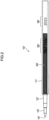
- Fig. 1 schematically illustrates the appearance of a writing implement refill 10 according to a first embodiment of the disclosure.
- the writing implement refill 10 of the present embodiment includes a cylindrical ink storage tube 11 that stores an ink 20 therein, a joint 12 attached to the leading end of the ink storage tube 11, and a ballpoint pen tip 13 attached to the leading end of the joint 12 and holding a writing ball 14 at the leading end.
- the ink storage tube 11 is made of a synthetic resin and an inside of the ink storage tube 11 is visible.
- the synthetic resin include a polypropylene resin.
- an engraved mark 30 is formed, on a surface of the ink storage tube 11, by the synthetic resin being foamed or carbonized or both. A reactive additive is blended in the synthetic resin.
- the engraved mark 30 is formed by applying laser marking to the surface of the ink storage tube 11, and protrudes from the surface of the ink storage tube 11.
- an engraved mark can be formed with a CO 2 laser marker having a wavelength of 10,600 nm, the engraved mark is not carbonized or foamed, only irregularities are formed, and sufficient visibility cannot be obtained. Meanwhile, since the wavelength of a fiber laser marker having a wavelength of about 1,000 nm is not the energy absorption band of the synthetic resin material, a laser beam is transmitted through the light transmissive synthetic resin material, and thus the engraved mark cannot be formed.
- the synthetic resin material itself does not react with laser light having a wavelength of from 800 to 1,500 nm, but this reactive additive absorbs the energy of the laser light and is excited, so that the synthetic resin can be discolored.
- the engraved mark 30 such as character information convexly protrudes due to foaming, carbonization, or both the foaming and the carbonization. Therefore, the visibility of the engraved mark 30 is more favorable than that of a mechanical engraved mark in which character information or the like is recessed with respect to the surface.
- the wavelength of the laser light is preferably from 1,000 to 1,100 nm.
- the reactive additive examples include a mixture of copper oxide and molybdenum oxide, a mixture of bismuth oxide and gallium oxide, a mixture of bismuth oxide, gallium oxide, and neodymium oxide, a pigment in which a thin flaky substrate of mica is coated with tin oxide doped with antimony, arsenic, bismuth, copper, gallium, germanium, or any oxide thereof, and a polymer substance to which copper hydroxide monophosphate or molybdenum oxide is added.
- the reactive additive only one of these may be used, or two or more thereof may be used in combination.
- the content of the reactive additive is preferably in a range of from 0.01 to 10 mass% with respect to the amount of the synthetic resin.
- the content of the reactive additive is 0.01 mass% or more, foaming, carbonization, or both of them in the ink storage tube are favorably generated.
- the content of the reactive additive is 10 mass% or less, the transparency of the ink storage tube 11 is secured, and the remaining amount and color of the ink 20 in the ink storage tube 11 can be visually recognized.
- the reactive additive absorbs the energy of the laser light and generates heat to foam the periphery, so that the portion becomes the engraved mark 30 having a white color. Moreover, in the synthetic resin, the reactive additive absorbs the energy of the laser light and generates heat to carbonize the periphery, so that the portion becomes the engraved mark 30 having a black color. Furthermore, since foaming and carbonization occur at the same time, the engraved mark 30 appears white or black depending on the background color. Note that the surface portion of the ink storage tube 11 is mainly foamed, so that the engraved mark 30 has a white color, and the engraved mark 30 has a black color due to the presence of carbide inside the synthetic resin.
- a writing implement refill 10' of a comparative embodiment illustrated in Fig. 2 is common in that it includes an ink storage tube 11' that stores an ink 20', a joint 12', and a ballpoint pen tip 13' that holds a writing ball 14' as in Fig. 1 , but is different in that an engraved mark 30' is mechanically made by thermal engraving. That is, the engraved mark 30' is microscopically merely a groove formed on the surface of the ink storage tube 11'. For this reason, it is difficult to provide a contrast between the character and its periphery, and it is difficult to visually recognize the character.
- the reactive additive absorbs the energy of the laser light, and the surrounding synthetic resin is foamed and carbonized, so that the engraved mark 30 has both a white color and a black color.
- the visibility is good even in a state in which the ink 20 is present or not present in the ink storage tube 11. That is, since the white color is superior at a portion where the ink 20 on the leading end side is present, the visibility of "REFILL" that is the character of the engraved mark 30 is secured.
- the black color is superior in a portion without the ink 20 on the trailing end side, the visibility of "2021", that is the character of the engraved mark 30, is secured.
- the synthetic resin itself forming the ink storage tube 11 is foamed and carbonized for printing, printing is less likely to disappear due to abrasion or the like than inkjet printing or hot stamping on the surface of the ink storage tube 11.
- the engraved mark 30 may be formed only by the foaming of a synthetic resin, or may be formed only by the carbonization of the synthetic resin.
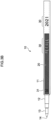
- Fig. 3A schematically illustrates the appearance of a writing implement refill 10 according to a second embodiment of the disclosure in a state of not being filled with the ink 20
- Fig. 3B schematically illustrates the appearance of the writing implement refill 10 according to the second embodiment of the disclosure in a state of being filled with the ink 20.
- the material and shape of the writing implement refill 10, a joint 12, and a ballpoint pen tip 13 including a writing ball 14 are as described in the first embodiment.
- the characters "REFILL" and "2021" as an engraved mark 30 are formed on the surface of the ink storage tube 11 as in the first embodiment.
- a two-dimensional code is formed as an information identifier 31 in the vicinity of the leading end of the surface of the ink storage tube 11 in addition to the engraved mark 30.
- the information identifier 31 is printed (for example, formed by printing) in the same color as that of the ink 20 stored in the ink storage tube 11. Therefore, as shown in Fig. 3B , since the color of the ink 20 contained in the ink storage tube 11 is visible from outside in a state in which the ink storage tube 11 is filled with the ink 20, the engraved mark is indistinguishable from the ink 20 and is difficult to visually recognize.
- a color difference ( ⁇ E*ab) between two colors of the ink 20 and the information identifier 31 through the ink storage tube 11 may be less than 1.6.
- the information identifier 31 may be formed as the engraved mark 30 obtained by carbonizing the surface of the ink storage tube 11 by laser marking. Since the laser marking can provide fine printing, a fine pattern such as a two-dimensional code can be clearly printed even on a thin object such as the writing implement refill 10. Moreover, it is easy to change the two-dimensional code as the information identifier 31 in each of the writing implement refill 10, and thus, it is also possible to identify the individual writing implement refill 10.
- a web page in which the product information of the writing implement refill 10 is disclosed can be linked to the two-dimensional code, or a so-called e-commerce site can be linked to the two-dimensional code, which can lead to product sales promotion.
- the color of the information identifier 31 and the color of the contained ink 20 are of an identical tone, so that the information identifier 31 cannot be read as the two-dimensional code.
- the background of the information identifier 31 becomes a different tone as illustrated in Fig. 3A , and the information identifier 31 can be read as the two-dimensional code.
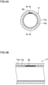
- Figs. 4A and 4B are cross-sectional views of an ink storage tube 11 of a writing implement refill 10 according to a third embodiment of the disclosure.
- the appearance of the writing implement refill 10 of the embodiment is similar to that of the second embodiment shown in Fig. 3A .
- Fig. 4A schematically illustrates a cross section corresponding to an A-A cross section of Fig. 3A
- Fig. 4B schematically illustrates a B-B cross section of Fig. 4A .
- the ink storage tube 11 has a multilayer structure of two or more layers, and includes an outermost layer 11a and at least one inner layer 11b (one in the embodiment) located inside the outermost layer 11a.
- a reactive additive is blended in the inner layer 11b and can develop color by laser marking, but the reactive additive is not blended in the outermost layer 11a. Since the ink storage tube 11 has such a multilayer structure, as shown in Figs. 4A and 4B , the engraved mark 30 generated by the color development by the laser marking is formed between the outermost layer 11a and the inner layer 11b.
- the ink storage tube 11 having such a multilayer structure can be formed by extrusion molding or injection molding.
- Fig. 4C schematically illustrates an A-A cross section of Fig. 3A
- Fig. 4D schematically illustrates a C-C cross section of Fig. 4C . Since the engraved mark 30 is formed on the surface of the ink storage tube 11 in the writing implement refills 10 of the first embodiment and the second embodiment, the engraved mark may disappear due to abrasion or the like, or the surface may be roughened due to the printing of the processing condition, so that a smooth state is not maintained in some cases.
- the engraved mark 30 is formed between the outermost layer 11a and the inner layer 11b as described above, in the writing implement refill 10 according to the third embodiment, the engraved mark 30 does not disappear due to the abrasion or the like of the surface of the ink storage tube 11. Moreover, since the engraved mark 30 is smooth without being formed on the surface of the ink storage tube 11, the ink storage tube 11 does not interfere with the inner peripheral surface of the axial barrel of a ballpoint pen when being stored inside the axial barrel, and does not interfere with back and forth movement inside the axial barrel due to a process of assembling the ballpoint pen, and a clicking operation and the like.
- the invention is applicable to a writing implement refill such as a ballpoint pen refill, a marker refill, or a felt pen refill.
Landscapes
- Engineering & Computer Science (AREA)
- Physics & Mathematics (AREA)
- Optics & Photonics (AREA)
- Mechanical Engineering (AREA)
- Plasma & Fusion (AREA)
- Pens And Brushes (AREA)
Abstract
Description
- The present invention relates to a writing implement refill in which an engraved mark is applied to an ink storage tube, and a method of engraving the writing implement refill.
- Japanese Patent Application Laid-Open (
JP-A) No. 2008-273096 JP-A No. 2010-155426 - In a case in which physical engraving is performed on a surface of an ink storage tube made of a synthetic resin, an engraved mark is sometimes difficult to see in a state in which an ink is contained therein. An object of an embodiment of the present application is to provide a writing implement refill with an engraved mark having favorable visibility in both a state in which an ink is contained in an ink storage tube and a state in which the ink is not contained in the ink storage tube.
- In view of the above problems, a writing implement refill according to a first embodiment of the present application includes: an ink storage tube made of a synthetic resin, an inside of the ink storage tube being visible; and an engraved mark formed, on a surface of the ink storage tube, by the synthetic resin being foamed or carbonized or both.
- In a second embodiment of the present application, in addition to the configuration of the first embodiment, it is preferable that a reactive additive is blended in the synthetic resin. When the reactive additive absorbs laser light to generate heat, the synthetic resin is foamed, carbonized, or foamed and carbonized, so that an engraved mark with favorable visibility is applied to the writing implement refill.
- Moreover, in a third embodiment of the present application, in addition to the configuration of the first embodiment or the second embodiment, it is preferable that the engraved mark protrudes from the surface of the ink storage tube from the viewpoint of visibility and durability of the engraved mark.
- Furthermore, in a fourth embodiment of the present application, in addition to the configuration of any one of the first to third embodiments, a color of an ink contained in the ink storage tube is visible from outside, and in addition to the engraved mark, an information identifier of a color of an identical tone to the color of the ink is formed on the surface of the ink storage tube. Here, the "color of an identical tone" refers to a color that makes it difficult to visually recognize the engraved mark since the engraved mark is indistinguishable from the ink in a state in which the portion of the engraved mark is filled with the ink. The "information identifier" refers to, for example, a two-dimensional code such as a barcode or a QR code (registered trademark).
- Furthermore, it is preferable that the ink storage tube has a multilayer structure of two or more layers including an outermost layer and at least one inner layer located inside the outermost layer, and the reactive additive is blended only in the inner layer. In other words, it is preferable that the reactive additive is not blended in the outermost layer.
- The engraved mark can be formed by applying laser marking to the surface of the ink storage tube.
- Since the embodiment of the present application is configured as described above, an engraved mark having favorable visibility can be applied to a writing implement refill in both a state in which an ink is contained in an ink storage tube and a state in which the ink is not contained in the ink storage tube.
-
-
Fig. 1 schematically illustrates the appearance of a writing implement refill according to a first embodiment of the present disclosure. -
Fig. 2 schematically illustrates the appearance of a writing implement refill according to a comparative embodiment. -
Fig. 3A schematically illustrates the appearance of a writing implement refill according to a second embodiment of the disclosure. -
Fig. 3B schematically illustrates the appearance of the writing implement refill according to the second embodiment of the disclosure. -
Fig. 4A schematically illustrates a writing implement refill according to a third embodiment of the disclosure in a cross section corresponding to A-A inFig. 3A . -
Fig. 4B schematically illustrates the writing implement refill according to the third embodiment of the disclosure in a cross section taken along line B-B inFig. 4A . -
Fig. 4C schematically illustrates the cross section of the writing implement refill according to the first embodiment and the second embodiment of the disclosure in a cross section taken along line A-A ofFig. 3A . -
Fig. 4D schematically illustrates the cross section of the writing implement refill according to the first embodiment and the second embodiment of the disclosure in a cross section taken along line C-C inFig. 4C . - Hereinafter, embodiments of the disclosure will be described with reference to the drawings. Note that, in the following description, a "leading end" refers to a side on which a writing leading end (for example, a writing ball) is provided in a writing implement refill, and a "trailing end" refers to the opposite side thereof. Moreover, the same reference numerals in the drawings indicate the same members or parts without any particular reference in the following description of the drawings. In each drawing, the left side of the drawing is a leading end side, and the right side is a trailing end side.
-
Fig. 1 schematically illustrates the appearance of awriting implement refill 10 according to a first embodiment of the disclosure. Thewriting implement refill 10 of the present embodiment includes a cylindricalink storage tube 11 that stores anink 20 therein, ajoint 12 attached to the leading end of theink storage tube 11, and aballpoint pen tip 13 attached to the leading end of thejoint 12 and holding awriting ball 14 at the leading end. - The
ink storage tube 11 is made of a synthetic resin and an inside of theink storage tube 11 is visible. Examples of the synthetic resin include a polypropylene resin. Moreover, an engravedmark 30 is formed, on a surface of theink storage tube 11, by the synthetic resin being foamed or carbonized or both. A reactive additive is blended in the synthetic resin. The engravedmark 30 is formed by applying laser marking to the surface of theink storage tube 11, and protrudes from the surface of theink storage tube 11. - Here, although, in a case in which laser marking is performed on an ink storage tube formed of a light transmissive synthetic resin material, an engraved mark can be formed with a CO2 laser marker having a wavelength of 10,600 nm, the engraved mark is not carbonized or foamed, only irregularities are formed, and sufficient visibility cannot be obtained. Meanwhile, since the wavelength of a fiber laser marker having a wavelength of about 1,000 nm is not the energy absorption band of the synthetic resin material, a laser beam is transmitted through the light transmissive synthetic resin material, and thus the engraved mark cannot be formed. Therefore, by blending a reactive additive in the synthetic resin material, it is possible to form an engraved mark such as character information even with laser light in a wavelength range that is not the energy absorption band of the synthetic resin material. That is, usually, the synthetic resin material itself does not react with laser light having a wavelength of from 800 to 1,500 nm, but this reactive additive absorbs the energy of the laser light and is excited, so that the synthetic resin can be discolored. The engraved
mark 30 such as character information convexly protrudes due to foaming, carbonization, or both the foaming and the carbonization. Therefore, the visibility of the engravedmark 30 is more favorable than that of a mechanical engraved mark in which character information or the like is recessed with respect to the surface. For example, in a case in which a polypropylene resin is used as a synthetic resin and laser marking is performed with a fiber laser marker, the wavelength of the laser light is preferably from 1,000 to 1,100 nm. - Examples of the reactive additive include a mixture of copper oxide and molybdenum oxide, a mixture of bismuth oxide and gallium oxide, a mixture of bismuth oxide, gallium oxide, and neodymium oxide, a pigment in which a thin flaky substrate of mica is coated with tin oxide doped with antimony, arsenic, bismuth, copper, gallium, germanium, or any oxide thereof, and a polymer substance to which copper hydroxide monophosphate or molybdenum oxide is added. As the reactive additive, only one of these may be used, or two or more thereof may be used in combination.
- The content of the reactive additive is preferably in a range of from 0.01 to 10 mass% with respect to the amount of the synthetic resin. When the content of the reactive additive is 0.01 mass% or more, foaming, carbonization, or both of them in the ink storage tube are favorably generated. When the content of the reactive additive is 10 mass% or less, the transparency of the
ink storage tube 11 is secured, and the remaining amount and color of theink 20 in theink storage tube 11 can be visually recognized. - In the synthetic resin, the reactive additive absorbs the energy of the laser light and generates heat to foam the periphery, so that the portion becomes the engraved
mark 30 having a white color. Moreover, in the synthetic resin, the reactive additive absorbs the energy of the laser light and generates heat to carbonize the periphery, so that the portion becomes theengraved mark 30 having a black color. Furthermore, since foaming and carbonization occur at the same time, theengraved mark 30 appears white or black depending on the background color. Note that the surface portion of theink storage tube 11 is mainly foamed, so that theengraved mark 30 has a white color, and theengraved mark 30 has a black color due to the presence of carbide inside the synthetic resin. - Here, a writing implement refill 10' of a comparative embodiment illustrated in
Fig. 2 is common in that it includes an ink storage tube 11' that stores an ink 20', a joint 12', and a ballpoint pen tip 13' that holds a writing ball 14' as inFig. 1 , but is different in that an engraved mark 30' is mechanically made by thermal engraving. That is, the engraved mark 30' is microscopically merely a groove formed on the surface of the ink storage tube 11'. For this reason, it is difficult to provide a contrast between the character and its periphery, and it is difficult to visually recognize the character. - On the other hand, in the writing implement refill of
Fig. 1 illustrating the first embodiment, the reactive additive absorbs the energy of the laser light, and the surrounding synthetic resin is foamed and carbonized, so that theengraved mark 30 has both a white color and a black color. Thus, the visibility is good even in a state in which theink 20 is present or not present in theink storage tube 11. That is, since the white color is superior at a portion where theink 20 on the leading end side is present, the visibility of "REFILL" that is the character of the engravedmark 30 is secured. On the other hand, since the black color is superior in a portion without theink 20 on the trailing end side, the visibility of "2021", that is the character of the engravedmark 30, is secured. - In the first embodiment, since the synthetic resin itself forming the
ink storage tube 11 is foamed and carbonized for printing, printing is less likely to disappear due to abrasion or the like than inkjet printing or hot stamping on the surface of theink storage tube 11. - Note that the
engraved mark 30 may be formed only by the foaming of a synthetic resin, or may be formed only by the carbonization of the synthetic resin. -
Fig. 3A schematically illustrates the appearance of a writing implementrefill 10 according to a second embodiment of the disclosure in a state of not being filled with theink 20, andFig. 3B schematically illustrates the appearance of the writing implementrefill 10 according to the second embodiment of the disclosure in a state of being filled with theink 20. The material and shape of the writing implementrefill 10, a joint 12, and aballpoint pen tip 13 including awriting ball 14 are as described in the first embodiment. Also in the embodiment, the characters "REFILL" and "2021" as anengraved mark 30 are formed on the surface of theink storage tube 11 as in the first embodiment. - Then, in the writing implement
refill 10 of the second embodiment, a two-dimensional code is formed as aninformation identifier 31 in the vicinity of the leading end of the surface of theink storage tube 11 in addition to theengraved mark 30. Theinformation identifier 31 is printed (for example, formed by printing) in the same color as that of theink 20 stored in theink storage tube 11. Therefore, as shown inFig. 3B , since the color of theink 20 contained in theink storage tube 11 is visible from outside in a state in which theink storage tube 11 is filled with theink 20, the engraved mark is indistinguishable from theink 20 and is difficult to visually recognize. Here, within a range of similar colors, for example, a color difference (ΔE*ab) between two colors of theink 20 and theinformation identifier 31 through theink storage tube 11 may be less than 1.6. - Note that, in a case in which the
ink 20 has a black color, for example, theinformation identifier 31 may be formed as theengraved mark 30 obtained by carbonizing the surface of theink storage tube 11 by laser marking. Since the laser marking can provide fine printing, a fine pattern such as a two-dimensional code can be clearly printed even on a thin object such as the writing implementrefill 10. Moreover, it is easy to change the two-dimensional code as theinformation identifier 31 in each of the writing implementrefill 10, and thus, it is also possible to identify the individual writing implementrefill 10. - By printing the
information identifier 31 on the writing implementrefill 10 in this manner, various types of information can be given to the writing implementrefill 10. For example, a web page in which the product information of the writing implementrefill 10 is disclosed can be linked to the two-dimensional code, or a so-called e-commerce site can be linked to the two-dimensional code, which can lead to product sales promotion. - Moreover, as illustrated in
Fig. 3B , when the writing implementrefill 10 is started to be used, the color of theinformation identifier 31 and the color of the containedink 20 are of an identical tone, so that theinformation identifier 31 cannot be read as the two-dimensional code. However, when theink 20 is consumed, the background of theinformation identifier 31 becomes a different tone as illustrated inFig. 3A , and theinformation identifier 31 can be read as the two-dimensional code. By using this, for example, a service of providing some sort of benefit information (for example, a purchase discount ticket or various points) to a consumer who has used up theink 20 of the writing implementrefill 10 is also possible. -
Figs. 4A and 4B are cross-sectional views of anink storage tube 11 of a writing implementrefill 10 according to a third embodiment of the disclosure. The appearance of the writing implementrefill 10 of the embodiment is similar to that of the second embodiment shown inFig. 3A .Fig. 4A schematically illustrates a cross section corresponding to an A-A cross section ofFig. 3A , andFig. 4B schematically illustrates a B-B cross section ofFig. 4A . Theink storage tube 11 has a multilayer structure of two or more layers, and includes anoutermost layer 11a and at least oneinner layer 11b (one in the embodiment) located inside theoutermost layer 11a. A reactive additive is blended in theinner layer 11b and can develop color by laser marking, but the reactive additive is not blended in theoutermost layer 11a. Since theink storage tube 11 has such a multilayer structure, as shown inFigs. 4A and 4B , theengraved mark 30 generated by the color development by the laser marking is formed between theoutermost layer 11a and theinner layer 11b. Theink storage tube 11 having such a multilayer structure can be formed by extrusion molding or injection molding. - Here, the cross-sectional views of the
ink storage tubes 11 of the writing implementrefills 10 of the first embodiment and the second embodiment are shown inFigs. 4C and 4D. Fig. 4C schematically illustrates an A-A cross section ofFig. 3A , andFig. 4D schematically illustrates a C-C cross section ofFig. 4C . Since theengraved mark 30 is formed on the surface of theink storage tube 11 in the writing implementrefills 10 of the first embodiment and the second embodiment, the engraved mark may disappear due to abrasion or the like, or the surface may be roughened due to the printing of the processing condition, so that a smooth state is not maintained in some cases. - On the other hand, since the
engraved mark 30 is formed between theoutermost layer 11a and theinner layer 11b as described above, in the writing implementrefill 10 according to the third embodiment, theengraved mark 30 does not disappear due to the abrasion or the like of the surface of theink storage tube 11. Moreover, since theengraved mark 30 is smooth without being formed on the surface of theink storage tube 11, theink storage tube 11 does not interfere with the inner peripheral surface of the axial barrel of a ballpoint pen when being stored inside the axial barrel, and does not interfere with back and forth movement inside the axial barrel due to a process of assembling the ballpoint pen, and a clicking operation and the like. - The invention is applicable to a writing implement refill such as a ballpoint pen refill, a marker refill, or a felt pen refill.
Claims (6)
- A writing implement refill, comprising:an ink storage tube made of a synthetic resin, an inside of the ink storage tube being visible; andan engraved mark formed, on a surface of the ink storage tube, by the synthetic resin being foamed or carbonized or both.
- The writing implement refill according to claim 1, wherein a reactive additive is blended in the synthetic resin.
- The writing implement refill according to claim 1, wherein the engraved mark protrudes from the surface of the ink storage tube.
- The writing implement refill according to claim 1, wherein:a color of an ink contained in the ink storage tube is visible from outside, andin addition to the engraved mark, an information identifier of a color of an identical tone to the color of the ink is formed on the surface of the ink storage tube.
- The writing implement refill according to claim 2, wherein:the ink storage tube has a multilayer structure of two or more layers including an outermost layer and at least one inner layer located inside the outermost layer, andthe reactive additive is blended only in the inner layer.
- A method of engraving a writing implement refill according to any one of claims 1 to 5, the method comprising forming the engraved mark by applying laser marking to the surface of the ink storage tube.
Applications Claiming Priority (4)
| Application Number | Priority Date | Filing Date | Title |
|---|---|---|---|
| JP2022000986 | 2022-01-06 | ||
| JP2022047019 | 2022-03-23 | ||
| JP2022182286A JP2023100581A (en) | 2022-01-06 | 2022-11-15 | Writing instrument refill and engraving method for writing instrument refill |
| PCT/JP2023/000175 WO2023132363A1 (en) | 2022-01-06 | 2023-01-06 | Writing instrument refill and method for marking writing instrument refill |
Publications (2)
| Publication Number | Publication Date |
|---|---|
| EP4461557A1 true EP4461557A1 (en) | 2024-11-13 |
| EP4461557A4 EP4461557A4 (en) | 2025-12-24 |
Family
ID=87073673
Family Applications (1)
| Application Number | Title | Priority Date | Filing Date |
|---|---|---|---|
| EP23737311.3A Pending EP4461557A4 (en) | 2022-01-06 | 2023-01-06 | WRITING INSTRUMENT REFILLING AND METHOD FOR MARKING THE WRITING INSTRUMENT REFILLING |
Country Status (4)
| Country | Link |
|---|---|
| US (1) | US20250115072A1 (en) |
| EP (1) | EP4461557A4 (en) |
| KR (1) | KR20240132292A (en) |
| WO (1) | WO2023132363A1 (en) |
Family Cites Families (12)
| Publication number | Priority date | Publication date | Assignee | Title |
|---|---|---|---|---|
| DE1511347A1 (en) * | 1966-11-08 | 1969-07-31 | Eduard Gehr Kunststoff Werk | Ballpoint pen lead tube |
| JPS5872084U (en) * | 1981-11-09 | 1983-05-16 | 株式会社 サクラクレパス | Ink consumption display device for writing instruments |
| JPH0595781U (en) * | 1992-05-31 | 1993-12-27 | 豊彦 藤沼 | Writing instrument |
| US6068422A (en) * | 1998-10-22 | 2000-05-30 | Eversharp Pen Co. | Ecologically beneficial refill for a pen including a level indicator and writeout scale |
| JP2006291196A (en) * | 2005-03-17 | 2006-10-26 | Mitsubishi Chemicals Corp | Resin composition for laser processing and bonding resin member using the same |
| JP2007062110A (en) * | 2005-08-30 | 2007-03-15 | Tombow Pencil Co Ltd | Writing instrument |
| JP4861890B2 (en) | 2007-05-01 | 2012-01-25 | ゼブラ株式会社 | Tubular body for writing instrument refill |
| JP2010125809A (en) * | 2008-12-01 | 2010-06-10 | Pilot Corporation | Laminate for laser marking, and laser marking method using the same |
| JP2010155426A (en) | 2009-01-05 | 2010-07-15 | Mitsubishi Pencil Co Ltd | Ball-point pen chip, ball-point pen refill, and ball-point pen |
| EP3674099B1 (en) * | 2017-08-23 | 2022-09-28 | Toppan Printing Co., Ltd. | Laminated body, identification, and identification verifying method |
| JP7006016B2 (en) * | 2017-08-24 | 2022-02-10 | 凸版印刷株式会社 | Personal authentication medium |
| JP2025501707A (en) * | 2021-12-16 | 2025-01-23 | ザ プロクター アンド ギャンブル カンパニー | High speed laser processes for marking articles |
-
2023
- 2023-01-06 WO PCT/JP2023/000175 patent/WO2023132363A1/en not_active Ceased
- 2023-01-06 US US18/726,214 patent/US20250115072A1/en active Pending
- 2023-01-06 KR KR1020247022940A patent/KR20240132292A/en active Pending
- 2023-01-06 EP EP23737311.3A patent/EP4461557A4/en active Pending
Also Published As
| Publication number | Publication date |
|---|---|
| WO2023132363A1 (en) | 2023-07-13 |
| KR20240132292A (en) | 2024-09-03 |
| US20250115072A1 (en) | 2025-04-10 |
| EP4461557A4 (en) | 2025-12-24 |
Similar Documents
| Publication | Publication Date | Title |
|---|---|---|
| CN105121173B (en) | Information writing film and sample storage body | |
| DE2936926A1 (en) | METHOD FOR THE PRODUCTION OF LIKE PLASTIC PARTS PROVIDED WITH DIFFERENT CHARACTERS, IN PARTICULAR PLASTIC DEVICE KEYS BY INJECTION MOLDING | |
| EP4461557A1 (en) | Writing instrument refill and method for marking writing instrument refill | |
| US3676646A (en) | Document with chemically developable precisely defined alphanumeric characters | |
| JP2023100581A (en) | Writing instrument refill and engraving method for writing instrument refill | |
| CN118541269A (en) | Writing instrument cartridge and method for engraving writing instrument cartridge | |
| WO2019230693A1 (en) | Writing implement | |
| JP7805171B2 (en) | Cylindrical structure and method for marking cylindrical structure | |
| JP2010155426A (en) | Ball-point pen chip, ball-point pen refill, and ball-point pen | |
| JP5035882B2 (en) | Digital pen reading paper and information reading method | |
| JPWO2024062756A5 (en) | ||
| JP2024095215A (en) | Writing instrument | |
| JP4001883B2 (en) | Ink ribbon of thermal transfer printer and manufacturing method thereof | |
| Gerhart | Methods of associating typewriter ribbons and correcting tapes with a questioned text | |
| JP2005202896A (en) | Anti-counterfeiting member and code mark reading system | |
| JP3190145U (en) | Information recording medium with digital watermark code | |
| Mulholland | Lasermarkable engineering resins | |
| JP2002096586A (en) | Personal authentication medium and its printing method | |
| JP2006175698A (en) | Thermal paper | |
| KR100827467B1 (en) | Tube Thermal Transfer Printing Machine | |
| JP2017094674A (en) | Erasing tool and writing utensil with erasing tool | |
| JP3532643B2 (en) | Heat resistant solvent resistant thermal transfer recording material | |
| JP3190264U (en) | Copying set | |
| US20040253043A1 (en) | Writing pen with built-in facility for creating an embossed and metallic coated surface under-layer for signature, to secure originality | |
| CN118862921A (en) | A fluorescent enhanced graphic marking method combining ink printing and thermal foaming digital inkjet coding technology |
Legal Events
| Date | Code | Title | Description |
|---|---|---|---|
| STAA | Information on the status of an ep patent application or granted ep patent |
Free format text: STATUS: THE INTERNATIONAL PUBLICATION HAS BEEN MADE |
|
| PUAI | Public reference made under article 153(3) epc to a published international application that has entered the european phase |
Free format text: ORIGINAL CODE: 0009012 |
|
| STAA | Information on the status of an ep patent application or granted ep patent |
Free format text: STATUS: REQUEST FOR EXAMINATION WAS MADE |
|
| 17P | Request for examination filed |
Effective date: 20240806 |
|
| AK | Designated contracting states |
Kind code of ref document: A1 Designated state(s): AL AT BE BG CH CY CZ DE DK EE ES FI FR GB GR HR HU IE IS IT LI LT LU LV MC ME MK MT NL NO PL PT RO RS SE SI SK SM TR |
|
| DAV | Request for validation of the european patent (deleted) | ||
| DAX | Request for extension of the european patent (deleted) | ||
| A4 | Supplementary search report drawn up and despatched |
Effective date: 20251126 |
|
| RIC1 | Information provided on ipc code assigned before grant |
Ipc: B43K 7/02 20060101AFI20251120BHEP Ipc: B43K 5/02 20060101ALI20251120BHEP Ipc: B43K 8/14 20060101ALI20251120BHEP Ipc: B43K 8/16 20060101ALI20251120BHEP |