EP4461546A1 - Dual mode label printer - Google Patents
Dual mode label printer Download PDFInfo
- Publication number
- EP4461546A1 EP4461546A1 EP24170451.9A EP24170451A EP4461546A1 EP 4461546 A1 EP4461546 A1 EP 4461546A1 EP 24170451 A EP24170451 A EP 24170451A EP 4461546 A1 EP4461546 A1 EP 4461546A1
- Authority
- EP
- European Patent Office
- Prior art keywords
- printer
- tear
- bar
- tear bar
- label
- Prior art date
- Legal status (The legal status is an assumption and is not a legal conclusion. Google has not performed a legal analysis and makes no representation as to the accuracy of the status listed.)
- Pending
Links
- 230000009977 dual effect Effects 0.000 title abstract description 5
- 238000000034 method Methods 0.000 claims description 15
- 230000007246 mechanism Effects 0.000 description 19
- 230000007704 transition Effects 0.000 description 6
- 230000008901 benefit Effects 0.000 description 3
- 230000008878 coupling Effects 0.000 description 2
- 238000010168 coupling process Methods 0.000 description 2
- 238000005859 coupling reaction Methods 0.000 description 2
- 230000007812 deficiency Effects 0.000 description 2
- 238000005516 engineering process Methods 0.000 description 2
- 208000027418 Wounds and injury Diseases 0.000 description 1
- 238000007792 addition Methods 0.000 description 1
- 230000006378 damage Effects 0.000 description 1
- 208000014674 injury Diseases 0.000 description 1
- 230000004048 modification Effects 0.000 description 1
- 238000012986 modification Methods 0.000 description 1
- 230000004044 response Effects 0.000 description 1
Images

Classifications
-
- B—PERFORMING OPERATIONS; TRANSPORTING
- B41—PRINTING; LINING MACHINES; TYPEWRITERS; STAMPS
- B41J—TYPEWRITERS; SELECTIVE PRINTING MECHANISMS, i.e. MECHANISMS PRINTING OTHERWISE THAN FROM A FORME; CORRECTION OF TYPOGRAPHICAL ERRORS
- B41J3/00—Typewriters or selective printing or marking mechanisms characterised by the purpose for which they are constructed
- B41J3/407—Typewriters or selective printing or marking mechanisms characterised by the purpose for which they are constructed for marking on special material
- B41J3/4075—Tape printers; Label printers
-
- B—PERFORMING OPERATIONS; TRANSPORTING
- B41—PRINTING; LINING MACHINES; TYPEWRITERS; STAMPS
- B41J—TYPEWRITERS; SELECTIVE PRINTING MECHANISMS, i.e. MECHANISMS PRINTING OTHERWISE THAN FROM A FORME; CORRECTION OF TYPOGRAPHICAL ERRORS
- B41J11/00—Devices or arrangements of selective printing mechanisms, e.g. ink-jet printers or thermal printers, for supporting or handling copy material in sheet or web form
- B41J11/66—Applications of cutting devices
- B41J11/70—Applications of cutting devices cutting perpendicular to the direction of paper feed
- B41J11/703—Cutting of tape
-
- B—PERFORMING OPERATIONS; TRANSPORTING
- B65—CONVEYING; PACKING; STORING; HANDLING THIN OR FILAMENTARY MATERIAL
- B65C—LABELLING OR TAGGING MACHINES, APPARATUS, OR PROCESSES
- B65C11/00—Manually-controlled or manually-operable label dispensers, e.g. modified for the application of labels to articles
- B65C11/02—Manually-controlled or manually-operable label dispensers, e.g. modified for the application of labels to articles having printing equipment
-
- B—PERFORMING OPERATIONS; TRANSPORTING
- B65—CONVEYING; PACKING; STORING; HANDLING THIN OR FILAMENTARY MATERIAL
- B65C—LABELLING OR TAGGING MACHINES, APPARATUS, OR PROCESSES
- B65C9/00—Details of labelling machines or apparatus
- B65C2009/0087—Details of handling backing sheets
- B65C2009/0093—Devices switching between a peelable and a non peelable position
Definitions
- the present application relates generally to a printer. More specifically, the present application relates generally to a dual mode label printer.
- Printers such as label printers, are used in a variety of industries, including retail, logistics, and healthcare. These devices allow users to print labels that include a face that can be adhered to a backing of the label.
- the face of the label may include information, such as bar codes, quick response (QR) codes, serial numbers, etc.
- the user of the printer may desire to tear a printed label from the printer with the backing still on to, for example, hand to a customer or place within a box.
- the user may also desire to have the option to tear the printed label by pulling the label toward them or away from them.
- the user of the printer may desire to have the printer remove the label from its backing to, for example, adhere the label to a package.
- existing technologies in this field do not allow for printers that operate in a first mode where the label can be torn by pulling the label either toward or away from the user and in a second mode where the label is removed from its backing by the printer.
- embodiments of the present disclosure provided herein include methods and apparatuses to provide for improved printers. More specifically, embodiments of the present disclosure provided herein include methods and apparatuses to provide for a dual mode printer that can operate in a tear mode and in a peel mode.
- a printer includes a presenter bar, a first tear bar positioned proximate to the presenter bar, and a second tear bar that is configured to move from a first position to a second position.
- the first position can be closer to the first tear bar than the second position.
- the second tear bar is coupled to or integral with the presenter bar.
- the second tear bar is configured to move from the first position to the second position when the presenter bar is rotated.
- the printer is configured to print labels.
- the first tear bar and the second tear bar can include an edge that is configured to tear the labels.
- the printer is configured to operate in a tear mode and in a peel mode.
- the printer can be in the tear mode and when the second tear bar is in the second position, the printer can be in the peel mode.
- the second tear bar when the second tear bar is in the first position, the second tear bar is configured to extend towards a first path defined by a label to be discharged from the printer. When the second tear bar is in the second position, the second tear bar can be configured to extend away from the first path.
- the second tear bar is configured to rotate from the first position to the second position.
- the printer includes a pocket.
- the second tear bar can be configured to be positioned at least partially outside of the pocket when the second tear bar is in the first position.
- the second tear bar can be configured to be positioned completely within the pocket when the second tear bar is in the second position.
- the second tear bar is configured to translate from the first position to the second position.
- a method of transitioning the printer of claim 1 from a tear mode to a peel mode includes moving the second tear bar from the first position to the second position.
- the method includes rotating the presenter bar of the printer to move the second tear bar from the first position to the second position.
- moving the second tear bar includes rotating the second tear bar.
- the method includes rotating a knob of the printer to move the second tear bar from the first position to the second position.
- moving the second tear bar includes translating the second tear bar.
- the method includes moving a switch of the printer to move the second tear bar from the first position to the second position.
- the method includes moving the second tear bar from being positioned at least partially outside of a pocket of the printer to being positioned completely within the pocket.
- a label printer configured to print one or more labels that each include a backing that a face of the label is adhered to.
- the label printer can be configured to operate in a tear mode and in a peel mode.
- the label printer can include a presenter bar configured to peel the backing from the face of the one or more labels when the label printer is in the peel mode, a first tear bar positioned proximate to the presenter bar configured to tear the one or more labels, and a second tear bar that is configured to tear the one or more labels when the label printer is in the tear mode.
- the second tear bar can be configured to move from a first position to a second position. The first position can be closer to the first tear bar than the second position. When the second tear bar is in the first position, the label printer can be in the tear mode. When the second tear bar is in the second position, the label printer can be in the peel mode.
- the second tear bar is coupled to or integral with the presenter bar.
- the second tear bar is configured to rotate from the first position to the second position.
- the second tear bar is configured to translate from the first position to the second position.
- exemplary means serving as an example, instance, or illustration. Any aspect or design described herein as "exemplary” is not necessarily to be construed as preferred or advantageous over other aspects or designs. Rather, use of the word exemplary is intended to present concepts in a concrete fashion.
- a particular feature may be disclosed with respect to only one of several implementations, such feature may be combined with one or more other features of the other implementations as may be desired and advantageous for any given or particular application.
- the terms “includes” and “including” and variants thereof are used in either the detailed description or the claims, these terms are intended to be inclusive in a manner similar to the term “comprising.”
- the term "or” is intended to mean an inclusive “or” rather than an exclusive “or”. That is, unless specified otherwise, or clear from context, "X employs A or B” is intended to mean any of the natural inclusive permutations. That is, if X employs A; X employs B; or X employs both A and B, then "X employs A or B” is satisfied under any of the foregoing instances.
- the articles “a” and “an” as used in this application and the appended claims should generally be construed to mean “one or more” unless specified otherwise or clear from context to be directed to a singular form.
- Coupled refers to both direct coupling, fixing, or attaching, as well as indirect coupling, fixing, or attaching through one or more intermediate components or features, unless otherwise specified herein.
- the term "positioned directly on” refers to a first component being positioned on a second component such that they make contact.
- the term “positioned directly between” refers to a first component being positioned between a second component and a third component such that the first component makes contact with both the second component and the third component.
- a first component that is "positioned between" a second component and a third component may or may not have contact with the second component and the third component.
- a first component that is "positioned between" a second component and a third component is positioned such that there may be other intervening components between the second component and the third component other than the first component.
- the printer 100 can define a forward direction F and an aft direction A.
- the printer 100 can be configured to print labels, such as labels that include barcodes or other information that is printed by the printer 100.
- the labels can be labels that include a backing, and the face of the label can be adhered to the backing of the label.
- the printer 100 can include an opening 101 for the labels to be discharged from.
- the printer 100 is configured as a portable printer, such as a portable thermal printer.
- the printer 100 may be worn by a user or may be coupled to equipment, such as a forklift or a lift truck.
- the printer 100 may also be set on a surface, such as the surface of a table.
- the printer 100 can be a dual mode printer.
- the printer 100 can be configured to operate in a tear mode and in a peel mode.
- the printer 100 can be configured to transition from the tear mode to the peel mode, and vice-versa.
- the printer 100 can be configured to allow a user to tear the label by pulling on the label in either the forward direction F (e.g., towards the user) or the aft direction A (e.g., away from the user), which will be discussed in more detail.
- the printer 100 can be configured to automatically peel one or more label from its backing and present the label to the user.
- the printer 100 can include a first drive component 110.
- the first drive component 110 can be configured to rotate.
- an electric motor can be provided that can rotate the first drive component 110.
- the first drive component 110 can be configured to move one or more labels towards the opening 101 of the printer 100.
- the label may be wedged between the first drive component 110 and a contact surface 115 to move the label towards the opening 101 of the printer 100.
- the path that the label makes as it is discharged from the opening 101 of the printer 100 may define a first path 111.
- the printer 100 can include a first tear bar 130.
- the first tear bar 130 can include a tearing edge 131.
- the tearing edge 131 can include serrations that facilitate the tearing of a label.
- the first tear bar 130 may be configured such that a user may pull a label that is positioned proximate to the opening 101 of the printer 100 in the forward direction F to tear the label.
- the first tear bar 130 can be firmly coupled to stationary components of the printer 100 such that it does not move in relation to the stationary components.
- the printer 100 can include a second tear bar 140.
- the second tear bar 140 can include a tearing edge 141.
- the tearing edge 141 can include serrations that facilitate the tearing of a label.
- a user may pull a label that is positioned proximate to the opening 101 of the printer 100 in the aft direction A to tear the label.
- the first tear bar 130 can be coupled to, or integral with, a movable component of the printer 100 such that it is allowed to move in relation to the stationary components of the printer 100.
- the printer 100 can include a peel mechanism 150.
- the peel mechanism 150 includes a cylindrical-shaped body.
- the peel mechanism 150 can include a half-circle shaped body, a triangular-shaped body, etc., to name a few examples.
- the peel mechanism 150 may be configured to peel the backing from a label when the printer 100 is in the peel mode.
- the printer 100 can include a second drive component 120.
- the second drive component 120 can be configured to rotate.
- an electric motor can be provided that can rotate the second drive component 120.
- the second drive component 120 can be configured to move the backing of one or more labels away from the opening 101 of the printer 100.
- the backing may be wedged between the first drive component 110 and the second drive component 120 to move the label away from the opening 101 of the printer 100 as the first drive component 110 and the second drive component 120 rotate.
- the path that the backing takes through the portion of the printer 100 may define a second path 112.
- the backing and the label may be moved from between the first drive component 110 and the contact surface 115 and towards the opening 101 of the printer 100 by the rotation of the first drive component 110.
- the path that the backing takes through the printer 100 which is defined by the second path 112, may fork-off from the path that the label takes, which defines the first path 111, as it is discharged from the opening 101 of the printer 100.
- the backing may extend partially around the peel mechanism 150, and towards and between the first drive component 110 and the second drive component 120.
- the second path 112 defined by the backing may extend from between the first drive component 110 and the contact surface 115, towards and partially around the peel mechanism 150, and towards and between the first drive component 110 and the second drive component 120 when the printer 100 is in the peel mode.
- the label may peel off from the backing, which causes the label to be expelled from the opening 101 of the printer 100, via the first path 111, while the backing of the label continues along the second path 112, when the printer 100 is in the peel mode.
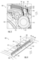
- the printer 100 can be configured to operate in a tear mode (as depicted in FIG. 2 ) and in a peel mode (as depicted in FIG. 3 ). As also briefly discussed, the printer 100 can be configured to transition from the tear mode to the peel mode, and vice-versa.
- the second tear bar 140 can be coupled to, or integral with, the peel mechanism 150.
- the peel mechanism 150 can be configured to rotate.
- the peel mechanism 150 can be configured to rotate at least 90 degrees, such as at least 90 degrees and up to 180 degrees, such as approximately (e.g., within 5 degrees of) 90 degrees, 150 degrees, or 180 degrees.
- a knob (not depicted) may be provided that allows a user to rotate the peel mechanism 150 and transition the printer 100 from the tear mode to the peel mode, and vice-versa.
- a cam and lock (not depicted) may be provided that allows a user to rotate the peel mechanism 150 and transition the printer 100 from the tear mode to the peel mode, and vice-versa.
- a lever (not depicted) is provided that allows a user to flip the peel mechanism 150 and transition the printer 100 from the tear mode to the peel mode, and vice-versa.
- the second tear bar 140 When the second tear bar 140 is coupled to, or integral with, the peel mechanism 150, the second tear bar 140 may also rotate at least 90 degrees, such as at least 90 degrees and up to 180 degrees.
- the second tear bar 140 may be configured to move from a first position, as depicted in FIG. 2 , to a second position, as depicted in FIG. 3 .
- the second tear bar 140 When the second tear bar 140 is in the first position (as depicted in FIG. 2 ), the second tear bar 140 may be positioned closer to the first tear bar 130 than when the second tear bar 140 is in the second position (as depicted in FIG. 3 ).
- the second tear bar 140 when the second tear bar 140 is in the second position, as depicted in FIG. 3 , the second tear bar 140 does not intersect or interfere with the second path 112, which defines the path that the backing of the label takes through the portion of the printer 100. As such, when the second tear bar 140 is in the second position, the ability of the peel mechanism 150 to facilitate the peeling of the backing of the label is not hindered. Additionally, when the second tear bar 140 is in the second position, the second tear bar 140 extends away from the first path 111, which defines the path the label takes towards and out of the opening 101 of the printer 100. As such, the second tear bar 140, when in the second position, does not interfere with the label exiting the opening 101 of the printer 100.
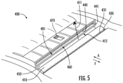
- FIGS. 4 and 5 perspective views of a portion of a printer 400 are provided, in accordance with an example embodiment. More specifically, FIG. 4 provides a view of the printer 400 in a tear mode and FIG. 5 provides a view of the printer 400 in peel mode.
- the printer 400 can be configured similarly to the printer 100 as described in reference to FIG. 1-3 . However, and as will be discussed further, the printer 400 of FIGS. 4 and 5 may include a second tear bar 440 that is not coupled to or integral with the peel mechanism 450.
- the printer 400 can include a first drive component 410 that can be configured to rotate.
- the first drive component 410 can be configured to move one or more labels towards the opening 401 of the printer 400.
- the label may be wedged between the first drive component 410 and a contact surface (not depicted in FIG. 4 or FIG. 5 ) to move the label towards the opening 401 of the printer 400.
- the path that the label makes as it is discharged from the opening 401 of the printer 400 may define a first path 411.
- the printer 400 can include a first tear bar 430.
- the first tear bar 430 can include a tearing edge 431.
- the first tear bar 430 can be firmly coupled to stationary components of the printer 400 such that it does not move in relation to the stationary components.
- the printer 400 can include a second tear bar 440.
- the second tear bar 440 can include a tearing edge 441.
- the second tear bar 440 can be coupled to, or integral with, a movable component of the printer 400 such that it is allowed to move in relation to the stationary components of the printer 400.
- the printer 400 can include a peel mechanism 450.
- the printer 400 can include a second drive component (not depicted in FIG. 4 or FIG. 5 ) that may be configured to rotate.
- the second drive component can be configured to move the backing of one or more labels away from the opening 401 of the printer 400.
- the backing may be wedged between the first drive component 410 and the second drive component to move the label away from the opening 401 of the printer 400 as the first drive component 410 and the second drive component rotate.
- the path that the backing takes through the portion of the printer 400 may define a second path 412 (partially depicted in FIG. 5 ).
- the label may peel off from the backing, which causes the label to be expelled from the opening 401 of the printer 400, via the first path 411, while the backing of the label continues along the second path 412, when the printer 400 is in the peel mode.
- the printer 400 can be configured to operate in a tear mode (as depicted in FIG. 4 ) and in a peel mode (as depicted in FIG. 5 ). As also briefly discussed, the printer 400 can be configured to transition from the tear mode to the peel mode, and vice-versa.
- the second tear bar 440 can be configured to move from a first position to a second position, and vice-versa.
- the second tear bar 440 can be configured to translate towards and away from the first tear bar 430.
- the printer 400 can include a pocket 460.
- the pocket 460 may define a substantially cuboid-shaped space and can substantially house the second tear bar 440 when the printer 400 is in the peel mode.
- the printer 400 can include a switch 470 that is mechanically coupled to the second tear bar 440.
- the switch 470 can be configured to move the second tear bar 440 towards and away from the first tear bar 430 by, for example, a user of the printer 400. Moving the second tear bar 440 toward the first tear bar 430 (e.g., to the first position) positions at least a portion of the second tear bar 440 outside of the pocket 460 of the printer 400, as depicted in FIG. 4 .
- the tearing edge 441 of the second tear bar 440 may be completely outside of the pocket 460 of the printer 400, which may allow a user to use the second tear bar 440 to tear a label.
- Moving the second tear bar 440 away from the first tear bar 430 e.g., to the second position
- the printer 100 and the printer 400 both have various benefits.
- the printer 100, 400 can be configured to operate in both a tear mode and in a peel mode, which increased the usability of the printer 100, 400.
- the user of the printer 100, 400 may desire to tear a label from the printer 100, 400 with the backing still on to, for example, hand to a customer or place within a box.
- the user may also desire to have the option to tear the printed label by pulling the label toward them (e.g., in the forward direction F) or away from them (e.g., in the aft direction A).
- the printer 100, 400 of the present disclosure allows the user to tear the label from the printer 100, 400 by pulling the label towards them (e.g., towards the first tear bar 130) and by pulling the label away from them (e.g., towards the second tear bar 140) when the printer 100, 400 is in the tear mode, as depicted in FIGS. 2 and 4 .
- the user of the printer 100, 400 may desire to have the printer 100, 400 remove the label from its backing (e.g., remove the label from its backing automatically) to, for example, adhere the peeled label to a package.
- the printer 100, 400 may peel the backing from the label via the peel mechanism 150.
- the second tear bar 140 is positioned away from where a hand of a user may be to grab the label, which may reduce the likelihood of injury from the second tear bar and may improve the safety of the printer 100, 400.
- printers may not allow for printers that operate in a first mode where the label can be torn by pulling the label either toward or away from the user and in a second mode where the label is removed from its backing by the printer.
- the printer 100, 400 of the present disclosure has various benefits over existing printers.
Landscapes
- Printers Characterized By Their Purpose (AREA)
Abstract
A dual mode printer (100) that includes a presenter bar, a first tear bar (130) positioned proximate to the presenter bar, and a second tear bar (140) that is configured to move from a first position to a second position is provided. The first position is closer to the first tear bar (130) than the second position.
Description
- The present application relates generally to a printer. More specifically, the present application relates generally to a dual mode label printer.
- Printers, such as label printers, are used in a variety of industries, including retail, logistics, and healthcare. These devices allow users to print labels that include a face that can be adhered to a backing of the label. The face of the label may include information, such as bar codes, quick response (QR) codes, serial numbers, etc.
- In some instances, the user of the printer may desire to tear a printed label from the printer with the backing still on to, for example, hand to a customer or place within a box. The user may also desire to have the option to tear the printed label by pulling the label toward them or away from them. Yet in other instances, the user of the printer may desire to have the printer remove the label from its backing to, for example, adhere the label to a package. However, existing technologies in this field do not allow for printers that operate in a first mode where the label can be torn by pulling the label either toward or away from the user and in a second mode where the label is removed from its backing by the printer.
- The inventors have identified numerous deficiencies and problems with the existing technologies in this field. Through applied effort, ingenuity, and innovation, many of these identified deficiencies and problems have been solved by developing solutions that are structured in accordance with the embodiments of the present disclosure, many examples of which are described in detail herein.
- In general, embodiments of the present disclosure provided herein include methods and apparatuses to provide for improved printers. More specifically, embodiments of the present disclosure provided herein include methods and apparatuses to provide for a dual mode printer that can operate in a tear mode and in a peel mode.
- In various aspects, a printer includes a presenter bar, a first tear bar positioned proximate to the presenter bar, and a second tear bar that is configured to move from a first position to a second position. The first position can be closer to the first tear bar than the second position.
- In various examples, the second tear bar is coupled to or integral with the presenter bar.
- In various examples, the second tear bar is configured to move from the first position to the second position when the presenter bar is rotated.
- In various examples, the printer is configured to print labels. The first tear bar and the second tear bar can include an edge that is configured to tear the labels.
- In various examples, the printer is configured to operate in a tear mode and in a peel mode. When the second tear bar is in the first position, the printer can be in the tear mode and when the second tear bar is in the second position, the printer can be in the peel mode.
- In various examples, when the second tear bar is in the first position, the second tear bar is configured to extend towards a first path defined by a label to be discharged from the printer. When the second tear bar is in the second position, the second tear bar can be configured to extend away from the first path.
- In various examples, the second tear bar is configured to rotate from the first position to the second position.
- In various examples, the printer includes a pocket. The second tear bar can be configured to be positioned at least partially outside of the pocket when the second tear bar is in the first position. The second tear bar can be configured to be positioned completely within the pocket when the second tear bar is in the second position.
- In various examples, the second tear bar is configured to translate from the first position to the second position.
- In various aspects, a method of transitioning the printer of claim 1 from a tear mode to a peel mode, the method includes moving the second tear bar from the first position to the second position.
- In various examples, the method includes rotating the presenter bar of the printer to move the second tear bar from the first position to the second position.
- In various examples, moving the second tear bar includes rotating the second tear bar.
- In various examples, the method includes rotating a knob of the printer to move the second tear bar from the first position to the second position.
- In various examples, moving the second tear bar includes translating the second tear bar.
- In various examples, the method includes moving a switch of the printer to move the second tear bar from the first position to the second position.
- In various examples, the method includes moving the second tear bar from being positioned at least partially outside of a pocket of the printer to being positioned completely within the pocket.
- In various aspects, a label printer configured to print one or more labels that each include a backing that a face of the label is adhered to. The label printer can be configured to operate in a tear mode and in a peel mode. The label printer can include a presenter bar configured to peel the backing from the face of the one or more labels when the label printer is in the peel mode, a first tear bar positioned proximate to the presenter bar configured to tear the one or more labels, and a second tear bar that is configured to tear the one or more labels when the label printer is in the tear mode. The second tear bar can be configured to move from a first position to a second position. The first position can be closer to the first tear bar than the second position. When the second tear bar is in the first position, the label printer can be in the tear mode. When the second tear bar is in the second position, the label printer can be in the peel mode.
- In various examples, the second tear bar is coupled to or integral with the presenter bar.
- In various examples, the second tear bar is configured to rotate from the first position to the second position.
- In various examples, the second tear bar is configured to translate from the first position to the second position.
- The above summary is provided merely for purposes of summarizing some example embodiments to provide a basic understanding of some aspects of the present disclosure. Accordingly, it will be appreciated that the above-described embodiments are merely examples and should not be construed to narrow the scope or spirit of the present disclosure in any way. It will be appreciated that the scope of the present disclosure encompasses many potential embodiments in addition to those here summarized, some of which will be further described below. Other features, aspects, and advantages of the subject matter will become apparent from the description, the drawings, and the claims.
- Having thus described certain example embodiments of the present disclosure in general terms above, non-limiting and non-exhaustive embodiments of the subject disclosure are described with reference to the following figures, which are not necessarily drawn to scale and wherein like reference numerals refer to like parts throughout the various views unless otherwise specified. The components illustrated in the figures may or may not be present in certain embodiments described herein. Some embodiments may include fewer (or more) components than those shown in the figures.
-
FIG. 1 provides a perspective view of a printer, in accordance with an example embodiment. -
FIG. 2 provides a cross-sectional view of a portion of the printer ofFIG. 1 in a tear mode, in accordance with an example embodiment. -
FIG. 3 provides a cross-sectional view of a portion of the printer ofFIG. 1 in a peel mode, in accordance with an example embodiment. -
FIG. 4 provides a cross-sectional view of a portion of a printer in a tear mode, in accordance with an example embodiment. -
FIG. 5 provides a cross-sectional view of a portion of the printer ofFIG. 4 in a peel mode, in accordance with an example embodiment. - One or more embodiments are now more fully described with reference to the accompanying drawings, wherein like reference numerals are used to refer to like elements throughout and in which some, but not all embodiments of the inventions are shown. In the following description, for purposes of explanation, numerous specific details are set forth in order to provide a thorough understanding of the various embodiments. It is evident, however, that the various embodiments can be practiced without these specific details. It should be understood that some, but not all embodiments are shown and described herein. Indeed, the embodiments may be embodied in many different forms, and accordingly this disclosure should not be construed as limited to the embodiments set forth herein. Rather, these embodiments are provided so that this disclosure will satisfy applicable legal requirements.
- As used herein, the term "exemplary" means serving as an example, instance, or illustration. Any aspect or design described herein as "exemplary" is not necessarily to be construed as preferred or advantageous over other aspects or designs. Rather, use of the word exemplary is intended to present concepts in a concrete fashion. In addition, while a particular feature may be disclosed with respect to only one of several implementations, such feature may be combined with one or more other features of the other implementations as may be desired and advantageous for any given or particular application. Furthermore, to the extent that the terms "includes" and "including" and variants thereof are used in either the detailed description or the claims, these terms are intended to be inclusive in a manner similar to the term "comprising."
- As used herein, the term "or" is intended to mean an inclusive "or" rather than an exclusive "or". That is, unless specified otherwise, or clear from context, "X employs A or B" is intended to mean any of the natural inclusive permutations. That is, if X employs A; X employs B; or X employs both A and B, then "X employs A or B" is satisfied under any of the foregoing instances. In addition, the articles "a" and "an" as used in this application and the appended claims should generally be construed to mean "one or more" unless specified otherwise or clear from context to be directed to a singular form.
- As used herein, the terms "coupled," "fixed," "attached to," and the like refer to both direct coupling, fixing, or attaching, as well as indirect coupling, fixing, or attaching through one or more intermediate components or features, unless otherwise specified herein.
- As used herein, the term "positioned directly on" refers to a first component being positioned on a second component such that they make contact. Similarly, as used herein, the term "positioned directly between" refers to a first component being positioned between a second component and a third component such that the first component makes contact with both the second component and the third component. In contrast, a first component that is "positioned between" a second component and a third component may or may not have contact with the second component and the third component. Additionally, a first component that is "positioned between" a second component and a third component is positioned such that there may be other intervening components between the second component and the third component other than the first component.
- Referring now to
FIG. 1 , a perspective view of aprinter 100 is provided, in accordance with an example embodiment. Theprinter 100 can define a forward direction F and an aft direction A. Theprinter 100 can be configured to print labels, such as labels that include barcodes or other information that is printed by theprinter 100. The labels can be labels that include a backing, and the face of the label can be adhered to the backing of the label. Theprinter 100 can include anopening 101 for the labels to be discharged from. - In various examples, the
printer 100 is configured as a portable printer, such as a portable thermal printer. When configured as a portable printer, theprinter 100 may be worn by a user or may be coupled to equipment, such as a forklift or a lift truck. Theprinter 100 may also be set on a surface, such as the surface of a table. - As will be explained further, the
printer 100 can be a dual mode printer. For example, theprinter 100 can be configured to operate in a tear mode and in a peel mode. For example, theprinter 100 can be configured to transition from the tear mode to the peel mode, and vice-versa. When theprinter 100 is in the tear mode, theprinter 100 can be configured to allow a user to tear the label by pulling on the label in either the forward direction F (e.g., towards the user) or the aft direction A (e.g., away from the user), which will be discussed in more detail. When theprinter 100 is in the peel mode, theprinter 100 can be configured to automatically peel one or more label from its backing and present the label to the user. - Referring now to
FIG. 2 , a cross-sectional view of a portion of theprinter 100 ofFIG. 1 in the tear mode is provided, in accordance with an example embodiment. Theprinter 100 can include afirst drive component 110. Thefirst drive component 110 can be configured to rotate. For example, an electric motor can be provided that can rotate thefirst drive component 110. Thefirst drive component 110 can be configured to move one or more labels towards the opening 101 of theprinter 100. For example, the label may be wedged between thefirst drive component 110 and acontact surface 115 to move the label towards the opening 101 of theprinter 100. The path that the label makes as it is discharged from theopening 101 of theprinter 100 may define afirst path 111. - The
printer 100 can include afirst tear bar 130. Thefirst tear bar 130 can include a tearingedge 131. For example, the tearingedge 131 can include serrations that facilitate the tearing of a label. Thefirst tear bar 130 may be configured such that a user may pull a label that is positioned proximate to theopening 101 of theprinter 100 in the forward direction F to tear the label. Thefirst tear bar 130 can be firmly coupled to stationary components of theprinter 100 such that it does not move in relation to the stationary components. - The
printer 100 can include asecond tear bar 140. Thesecond tear bar 140 can include a tearingedge 141. For example, the tearingedge 141 can include serrations that facilitate the tearing of a label. For example, when theprinter 100 is in the tear mode, a user may pull a label that is positioned proximate to theopening 101 of theprinter 100 in the aft direction A to tear the label. As will be discussed further, thefirst tear bar 130 can be coupled to, or integral with, a movable component of theprinter 100 such that it is allowed to move in relation to the stationary components of theprinter 100. - Referring now to
FIG. 3 , a cross-sectional view of a portion of theprinter 100 ofFIG. 1 in the peel mode is provided, in accordance with an example embodiment. Theprinter 100 can include apeel mechanism 150. In various examples, and as depicted, thepeel mechanism 150 includes a cylindrical-shaped body. However, thepeel mechanism 150 can include a half-circle shaped body, a triangular-shaped body, etc., to name a few examples. Thepeel mechanism 150 may be configured to peel the backing from a label when theprinter 100 is in the peel mode. - The
printer 100 can include asecond drive component 120. Thesecond drive component 120 can be configured to rotate. For example, an electric motor can be provided that can rotate thesecond drive component 120. Thesecond drive component 120 can be configured to move the backing of one or more labels away from theopening 101 of theprinter 100. For example, the backing may be wedged between thefirst drive component 110 and thesecond drive component 120 to move the label away from theopening 101 of theprinter 100 as thefirst drive component 110 and thesecond drive component 120 rotate. - The path that the backing takes through the portion of the
printer 100 may define asecond path 112. For example, and as depicted inFIG. 3 , the backing and the label may be moved from between thefirst drive component 110 and thecontact surface 115 and towards the opening 101 of theprinter 100 by the rotation of thefirst drive component 110. The path that the backing takes through theprinter 100, which is defined by thesecond path 112, may fork-off from the path that the label takes, which defines thefirst path 111, as it is discharged from theopening 101 of theprinter 100. For example, the backing may extend partially around thepeel mechanism 150, and towards and between thefirst drive component 110 and thesecond drive component 120. As such, thesecond path 112 defined by the backing may extend from between thefirst drive component 110 and thecontact surface 115, towards and partially around thepeel mechanism 150, and towards and between thefirst drive component 110 and thesecond drive component 120 when theprinter 100 is in the peel mode. - As the backing extends partially around the
peel mechanism 150, the label may peel off from the backing, which causes the label to be expelled from theopening 101 of theprinter 100, via thefirst path 111, while the backing of the label continues along thesecond path 112, when theprinter 100 is in the peel mode. - As briefly discussed, the
printer 100 can be configured to operate in a tear mode (as depicted inFIG. 2 ) and in a peel mode (as depicted inFIG. 3 ). As also briefly discussed, theprinter 100 can be configured to transition from the tear mode to the peel mode, and vice-versa. In various examples, and as depicted inFIGS. 2 and3 , thesecond tear bar 140 can be coupled to, or integral with, thepeel mechanism 150. Thepeel mechanism 150 can be configured to rotate. For example, thepeel mechanism 150 can be configured to rotate at least 90 degrees, such as at least 90 degrees and up to 180 degrees, such as approximately (e.g., within 5 degrees of) 90 degrees, 150 degrees, or 180 degrees. In various examples, a knob (not depicted) may be provided that allows a user to rotate thepeel mechanism 150 and transition theprinter 100 from the tear mode to the peel mode, and vice-versa. In various examples, a cam and lock (not depicted) may be provided that allows a user to rotate thepeel mechanism 150 and transition theprinter 100 from the tear mode to the peel mode, and vice-versa. In various examples, a lever (not depicted) is provided that allows a user to flip thepeel mechanism 150 and transition theprinter 100 from the tear mode to the peel mode, and vice-versa. - When the
second tear bar 140 is coupled to, or integral with, thepeel mechanism 150, thesecond tear bar 140 may also rotate at least 90 degrees, such as at least 90 degrees and up to 180 degrees. For example, thesecond tear bar 140 may be configured to move from a first position, as depicted inFIG. 2 , to a second position, as depicted inFIG. 3 . When thesecond tear bar 140 is in the first position (as depicted inFIG. 2 ), thesecond tear bar 140 may be positioned closer to thefirst tear bar 130 than when thesecond tear bar 140 is in the second position (as depicted inFIG. 3 ). - Notably, when the
second tear bar 140 is in the second position, as depicted inFIG. 3 , thesecond tear bar 140 does not intersect or interfere with thesecond path 112, which defines the path that the backing of the label takes through the portion of theprinter 100. As such, when thesecond tear bar 140 is in the second position, the ability of thepeel mechanism 150 to facilitate the peeling of the backing of the label is not hindered. Additionally, when thesecond tear bar 140 is in the second position, thesecond tear bar 140 extends away from thefirst path 111, which defines the path the label takes towards and out of theopening 101 of theprinter 100. As such, thesecond tear bar 140, when in the second position, does not interfere with the label exiting theopening 101 of theprinter 100. - Referring now to
FIGS. 4 and5 , perspective views of a portion of aprinter 400 are provided, in accordance with an example embodiment. More specifically,FIG. 4 provides a view of theprinter 400 in a tear mode andFIG. 5 provides a view of theprinter 400 in peel mode. Theprinter 400 can be configured similarly to theprinter 100 as described in reference toFIG. 1-3 . However, and as will be discussed further, theprinter 400 ofFIGS. 4 and5 may include asecond tear bar 440 that is not coupled to or integral with thepeel mechanism 450. - Referring to
FIG. 4 , which depicts theprinter 400 in the tear mode, theprinter 400 can include afirst drive component 410 that can be configured to rotate. Thefirst drive component 410 can be configured to move one or more labels towards the opening 401 of theprinter 400. For example, the label may be wedged between thefirst drive component 410 and a contact surface (not depicted inFIG. 4 orFIG. 5 ) to move the label towards the opening 401 of theprinter 400. The path that the label makes as it is discharged from theopening 401 of theprinter 400 may define afirst path 411. - The
printer 400 can include afirst tear bar 430. Thefirst tear bar 430 can include a tearingedge 431. Thefirst tear bar 430 can be firmly coupled to stationary components of theprinter 400 such that it does not move in relation to the stationary components. - The
printer 400 can include asecond tear bar 440. Thesecond tear bar 440 can include a tearingedge 441. As will be discussed further, thesecond tear bar 440 can be coupled to, or integral with, a movable component of theprinter 400 such that it is allowed to move in relation to the stationary components of theprinter 400. - Referring to
FIG. 5 , which depicts theprinter 400 in the peel mode, theprinter 400 can include apeel mechanism 450. Like theprinter 100, theprinter 400 can include a second drive component (not depicted inFIG. 4 orFIG. 5 ) that may be configured to rotate. The second drive component can be configured to move the backing of one or more labels away from theopening 401 of theprinter 400. For example, the backing may be wedged between thefirst drive component 410 and the second drive component to move the label away from theopening 401 of theprinter 400 as thefirst drive component 410 and the second drive component rotate. The path that the backing takes through the portion of theprinter 400 may define a second path 412 (partially depicted inFIG. 5 ). As the backing extends partially around thepeel mechanism 450, the label may peel off from the backing, which causes the label to be expelled from theopening 401 of theprinter 400, via thefirst path 411, while the backing of the label continues along thesecond path 412, when theprinter 400 is in the peel mode. - As briefly discussed, the
printer 400 can be configured to operate in a tear mode (as depicted inFIG. 4 ) and in a peel mode (as depicted inFIG. 5 ). As also briefly discussed, theprinter 400 can be configured to transition from the tear mode to the peel mode, and vice-versa. In various examples, and as depicted inFIGS. 4 and5 , thesecond tear bar 440 can be configured to move from a first position to a second position, and vice-versa. For example, thesecond tear bar 440 can be configured to translate towards and away from thefirst tear bar 430. For example, theprinter 400 can include apocket 460. Thepocket 460 may define a substantially cuboid-shaped space and can substantially house thesecond tear bar 440 when theprinter 400 is in the peel mode. Theprinter 400 can include aswitch 470 that is mechanically coupled to thesecond tear bar 440. Theswitch 470 can be configured to move thesecond tear bar 440 towards and away from thefirst tear bar 430 by, for example, a user of theprinter 400. Moving thesecond tear bar 440 toward the first tear bar 430 (e.g., to the first position) positions at least a portion of thesecond tear bar 440 outside of thepocket 460 of theprinter 400, as depicted inFIG. 4 . For example, the tearingedge 441 of thesecond tear bar 440 may be completely outside of thepocket 460 of theprinter 400, which may allow a user to use thesecond tear bar 440 to tear a label. Moving thesecond tear bar 440 away from the first tear bar 430 (e.g., to the second position) positions thesecond tear bar 440 completely or substantially within thepocket 460 of theprinter 400, as depicted inFIG. 5 . - The
printer 100 and theprinter 400 both have various benefits. For example, theprinter printer printer printer printer printer printer FIGS. 2 and4 . - Yet in other instances, the user of the
printer printer printer FIGS. 3 and5 , theprinter peel mechanism 150. Notably, when theprinter second tear bar 140 is positioned away from where a hand of a user may be to grab the label, which may reduce the likelihood of injury from the second tear bar and may improve the safety of theprinter - Existing printers may not allow for printers that operate in a first mode where the label can be torn by pulling the label either toward or away from the user and in a second mode where the label is removed from its backing by the printer. As such, the
printer - The above descriptions of various embodiments of the subject disclosure and corresponding figures and what is described in the Abstract, are described herein for illustrative purposes, and are not intended to be exhaustive or to limit the disclosed embodiments to the precise forms disclosed. It is to be understood that one of ordinary skill in the art may recognize that other embodiments having modifications, permutations, combinations, and additions can be implemented for performing the same, similar, alternative, or substitute functions of the disclosed subject matter, and are therefore considered within the scope of this disclosure. Therefore, the disclosed subject matter should not be limited to any single embodiment described herein, but rather should be construed in breadth and scope in accordance with the appended claims below. Moreover, although the foregoing descriptions and the associated drawings describe example embodiments in the context of certain example combinations of elements and/or functions, it should be appreciated that different combinations of elements and/or functions may be provided by alternative embodiments without departing from the scope of the appended claims. In this regard, for example, different combinations of elements and/or functions than those explicitly described above are also contemplated as may be set forth in some of the appended claims. Although specific terms are employed herein, they are used in a generic and descriptive sense only and not for purposes of limitation.
Claims (15)
- A printer comprising:a presenter bar;a first tear bar positioned proximate to the presenter bar; anda second tear bar that is configured to move from a first position to a second position,wherein the first position is closer to the first tear bar than the second position.
- The printer of claim 1, wherein the second tear bar is coupled to or integral with the presenter bar.
- The printer of claim 2, wherein the second tear bar is configured to move from the first position to the second position when the presenter bar is rotated.
- The printer of claim 1, wherein the printer is configured to print labels, and wherein the first tear bar and the second tear bar comprise an edge that is configured to tear the labels.
- The printer of claim 1, wherein the printer is configured to operate in a tear mode and in a peel mode, and
wherein when the second tear bar is in the first position, the printer is in the tear mode and when the second tear bar is in the second position, the printer is in the peel mode. - The printer of claim 1, wherein when the second tear bar is in the first position, the second tear bar is configured to extend towards a first path defined by a label to be discharged from the printer, and
wherein when the second tear bar is in the second position, the second tear bar is configured to extend away from the first path. - The printer of claim 1, wherein the second tear bar is configured to rotate from the first position to the second position.
- The printer of claim 1, further comprising a pocket, wherein the second tear bar is configured to be positioned at least partially outside of the pocket when the second tear bar is in the first position, and wherein the second tear bar is configured to be positioned completely within the pocket when the second tear bar is in the second position.
- The printer of claim 1, wherein the second tear bar is configured to translate from the first position to the second position.
- A method of transitioning the printer of claim 1 from a tear mode to a peel mode, the method comprising:
moving the second tear bar from the first position to the second position. - The method of claim 10, further comprising rotating the presenter bar of the printer to move the second tear bar from the first position to the second position.
- The method of claim 10, wherein moving the second tear bar comprises rotating the second tear bar.
- The method of claim 10, further comprising rotating a knob of the printer to move the second tear bar from the first position to the second position.
- The method of claim 10, wherein moving the second tear bar comprises translating the second tear bar.
- The method of claim 10, further comprising moving a switch of the printer to move the second tear bar from the first position to the second position.
Applications Claiming Priority (1)
| Application Number | Priority Date | Filing Date | Title |
|---|---|---|---|
| US18/315,690 US12434494B2 (en) | 2023-05-11 | 2023-05-11 | Dual mode label printer |
Publications (1)
| Publication Number | Publication Date |
|---|---|
| EP4461546A1 true EP4461546A1 (en) | 2024-11-13 |
Family
ID=90735278
Family Applications (1)
| Application Number | Title | Priority Date | Filing Date |
|---|---|---|---|
| EP24170451.9A Pending EP4461546A1 (en) | 2023-05-11 | 2024-04-16 | Dual mode label printer |
Country Status (3)
| Country | Link |
|---|---|
| US (1) | US12434494B2 (en) |
| EP (1) | EP4461546A1 (en) |
| CN (1) | CN118977513A (en) |
Citations (2)
| Publication number | Priority date | Publication date | Assignee | Title |
|---|---|---|---|---|
| US20130108346A1 (en) * | 2010-04-12 | 2013-05-02 | Zih Corp. | Label peeling, universal printheads and related methods |
| US20180304649A1 (en) * | 2017-04-20 | 2018-10-25 | Datamax-O'neil Corporation | Self-strip media module |
Family Cites Families (11)
| Publication number | Priority date | Publication date | Assignee | Title |
|---|---|---|---|---|
| JP4107261B2 (en) | 2003-11-14 | 2008-06-25 | セイコーエプソン株式会社 | Printer with cutter mechanism |
| JP2007083639A (en) | 2005-09-26 | 2007-04-05 | Seiko Epson Corp | Label processing mechanism and printer |
| US7510343B1 (en) | 2008-06-03 | 2009-03-31 | International Business Machines Corporation | Method of retracting a tear bar in a printer |
| JP6068023B2 (en) | 2012-07-04 | 2017-01-25 | サトーホールディングス株式会社 | Printer |
| JP2014061647A (en) | 2012-09-21 | 2014-04-10 | Sato Holdings Corp | Label printer |
| US9248672B2 (en) | 2013-09-25 | 2016-02-02 | Brother Kogyo Kabushiki Kaisha | Printer with cutting device having holding portion for holding blade in cutting position |
| US9493017B2 (en) | 2015-02-13 | 2016-11-15 | Zih Corp. | Modular print drive assembly and platen assembly |
| JP7207035B2 (en) | 2019-03-13 | 2023-01-18 | ブラザー工業株式会社 | Cutting device and printing device |
| JP7318411B2 (en) | 2019-08-09 | 2023-08-01 | セイコーエプソン株式会社 | printer |
| JP7581809B2 (en) | 2020-12-04 | 2024-11-13 | ブラザー工業株式会社 | Cutting and printing equipment |
| JP7545667B2 (en) | 2020-12-28 | 2024-09-05 | ブラザー工業株式会社 | Printing device |
-
2023
- 2023-05-11 US US18/315,690 patent/US12434494B2/en active Active
-
2024
- 2024-03-27 CN CN202410358610.2A patent/CN118977513A/en active Pending
- 2024-04-16 EP EP24170451.9A patent/EP4461546A1/en active Pending
Patent Citations (2)
| Publication number | Priority date | Publication date | Assignee | Title |
|---|---|---|---|---|
| US20130108346A1 (en) * | 2010-04-12 | 2013-05-02 | Zih Corp. | Label peeling, universal printheads and related methods |
| US20180304649A1 (en) * | 2017-04-20 | 2018-10-25 | Datamax-O'neil Corporation | Self-strip media module |
Also Published As
| Publication number | Publication date |
|---|---|
| US20240375419A1 (en) | 2024-11-14 |
| CN118977513A (en) | 2024-11-19 |
| US12434494B2 (en) | 2025-10-07 |
Similar Documents
| Publication | Publication Date | Title |
|---|---|---|
| US12397567B2 (en) | Label, peeling, universal printheads and related methods | |
| CN101607487B (en) | Printer with a cutter | |
| EP1674274B1 (en) | Tape printer with tape jam eliminating control in relation to tape cutting operation | |
| CN108819509B (en) | Tape box | |
| EP2556963B1 (en) | Printer convenient for maintaining paper cutting device | |
| US20200398593A1 (en) | Printer apparatus | |
| JP5844139B2 (en) | Peeling device and label printer provided with peeling device | |
| CN106103114B (en) | Tape drum and tape printing apparatus | |
| JP2006181755A (en) | Tape printer | |
| US12434494B2 (en) | Dual mode label printer | |
| JP2020069747A (en) | Label printer | |
| US20090148217A1 (en) | Thermal printer | |
| JP6007708B2 (en) | Tape cartridge | |
| JPH1077015A (en) | Label peeling device | |
| US12011940B2 (en) | Label printer | |
| JP5289881B2 (en) | Tape printer | |
| JP3805898B2 (en) | Label printer | |
| CN116438082B (en) | printer | |
| US7785025B2 (en) | Point of sale printer including an automated cover opening apparatus | |
| US8783323B2 (en) | Platen opening mechanism in portable labeling machine | |
| US20220411122A1 (en) | Label printer | |
| JP5517545B2 (en) | Printer device | |
| CN215662562U (en) | Movable paper guide structure of volume label printer | |
| JPWO2006085398A1 (en) | Tape cutter and cutting device | |
| JP2005219342A (en) | Label printer |
Legal Events
| Date | Code | Title | Description |
|---|---|---|---|
| PUAI | Public reference made under article 153(3) epc to a published international application that has entered the european phase |
Free format text: ORIGINAL CODE: 0009012 |
|
| STAA | Information on the status of an ep patent application or granted ep patent |
Free format text: STATUS: REQUEST FOR EXAMINATION WAS MADE |
|
| 17P | Request for examination filed |
Effective date: 20240416 |
|
| AK | Designated contracting states |
Kind code of ref document: A1 Designated state(s): AL AT BE BG CH CY CZ DE DK EE ES FI FR GB GR HR HU IE IS IT LI LT LU LV MC ME MK MT NL NO PL PT RO RS SE SI SK SM TR |
|
| RAP3 | Party data changed (applicant data changed or rights of an application transferred) |
Owner name: HAND HELD PRODUCTS, INC. |