EP4461469A1 - Apparatus for driving fasteners - Google Patents
Apparatus for driving fasteners Download PDFInfo
- Publication number
- EP4461469A1 EP4461469A1 EP24174991.0A EP24174991A EP4461469A1 EP 4461469 A1 EP4461469 A1 EP 4461469A1 EP 24174991 A EP24174991 A EP 24174991A EP 4461469 A1 EP4461469 A1 EP 4461469A1
- Authority
- EP
- European Patent Office
- Prior art keywords
- fastener
- substrate
- probe
- retractable
- relative
- Prior art date
- Legal status (The legal status is an assumption and is not a legal conclusion. Google has not performed a legal analysis and makes no representation as to the accuracy of the status listed.)
- Pending
Links
Images






Classifications
-
- B—PERFORMING OPERATIONS; TRANSPORTING
- B25—HAND TOOLS; PORTABLE POWER-DRIVEN TOOLS; MANIPULATORS
- B25C—HAND-HELD NAILING OR STAPLING TOOLS; MANUALLY OPERATED PORTABLE STAPLING TOOLS
- B25C1/00—Hand-held nailing tools; Nail feeding devices
- B25C1/04—Hand-held nailing tools; Nail feeding devices operated by fluid pressure, e.g. by air pressure
- B25C1/047—Mechanical details
-
- B—PERFORMING OPERATIONS; TRANSPORTING
- B25—HAND TOOLS; PORTABLE POWER-DRIVEN TOOLS; MANIPULATORS
- B25C—HAND-HELD NAILING OR STAPLING TOOLS; MANUALLY OPERATED PORTABLE STAPLING TOOLS
- B25C1/00—Hand-held nailing tools; Nail feeding devices
- B25C1/08—Hand-held nailing tools; Nail feeding devices operated by combustion pressure
-
- B—PERFORMING OPERATIONS; TRANSPORTING
- B25—HAND TOOLS; PORTABLE POWER-DRIVEN TOOLS; MANIPULATORS
- B25C—HAND-HELD NAILING OR STAPLING TOOLS; MANUALLY OPERATED PORTABLE STAPLING TOOLS
- B25C1/00—Hand-held nailing tools; Nail feeding devices
- B25C1/001—Nail feeding devices
-
- B—PERFORMING OPERATIONS; TRANSPORTING
- B25—HAND TOOLS; PORTABLE POWER-DRIVEN TOOLS; MANIPULATORS
- B25C—HAND-HELD NAILING OR STAPLING TOOLS; MANUALLY OPERATED PORTABLE STAPLING TOOLS
- B25C1/00—Hand-held nailing tools; Nail feeding devices
- B25C1/08—Hand-held nailing tools; Nail feeding devices operated by combustion pressure
- B25C1/10—Hand-held nailing tools; Nail feeding devices operated by combustion pressure generated by detonation of a cartridge
- B25C1/18—Details and accessories, e.g. splinter guards, spall minimisers
- B25C1/188—Arrangements at the forward end of the barrel, e.g. splinter guards, spall minimisers, safety arrangements, silencers, bolt retainers
-
- B—PERFORMING OPERATIONS; TRANSPORTING
- B25—HAND TOOLS; PORTABLE POWER-DRIVEN TOOLS; MANIPULATORS
- B25C—HAND-HELD NAILING OR STAPLING TOOLS; MANUALLY OPERATED PORTABLE STAPLING TOOLS
- B25C7/00—Accessories for nailing or stapling tools, e.g. supports
-
- B—PERFORMING OPERATIONS; TRANSPORTING
- B25—HAND TOOLS; PORTABLE POWER-DRIVEN TOOLS; MANIPULATORS
- B25C—HAND-HELD NAILING OR STAPLING TOOLS; MANUALLY OPERATED PORTABLE STAPLING TOOLS
- B25C1/00—Hand-held nailing tools; Nail feeding devices
- B25C1/001—Nail feeding devices
- B25C1/003—Nail feeding devices for belts of nails
Definitions
- the present disclosure relates to an apparatus for driving fasteners. More particularly, various embodiments of the present disclosure relate to nail driving apparatus such as nail driving apparatus that are powered by combustion or pneumatically and fed with a coiled storage of fasteners or otherwise.
- the nail driving apparatus can be but is not limited to the type used for fastening cladding to a structure.
- Various embodiments of the present disclosure provide an apparatus for driving fasteners that alleviates or at least ameliorates one or more disadvantages of existing methods and apparatuses used in fastening cladding.
- an apparatus for driving fasteners that includes a housing, a cylinder in the housing, a driving piston in the housing and arranged for driving a fastener from the apparatus into a substrate, the piston being arranged for reciprocating movement in the housing relative to the cylinder, a charge supply in the housing for feeding a charge to a combustion chamber of the cylinder where the charge is combusted to drive movement of the piston relative to the cylinder.
- the apparatus includes a guidance system connected to the housing and configured to guide the apparatus relative to the substrate.
- the guidance system is in the form of a positive placement system.
- the positive placement system includes a retractable probe configured to be placed on a receiving location for locating the apparatus relative to the substrate, and wherein the retractable probe is configured to subsequently retract to make way for a fastener to be driven at the receiving location.
- the probe is configured to clear a raceway of the apparatus, thereby making way for the fastener to be driven.
- the positive placement system includes a mechanism configured to progressively move the probe rearward toward the housing and then upward for avoiding damage to the substrate and for aligning the raceway with a center of a hole for receiving the fastener.
- the fasteners are stored in a coil formation in a housing of the coil feed.
- the apparatus includes a guidance system connected to the housing and for guiding the apparatus relative to the substrate, wherein the guidance system is in the form of a positive placement system, the positive placement system includes a retractable probe configured to be placed on a receiving location of a substrate for locating the apparatus relative to the substrate, and wherein the retractable probe is configured to subsequently retract toward the housing to make way for the fastener to be driven at the receiving location.
- the probe is configured to clear a raceway of the apparatus, thereby making way for the fastener to be driven.
- the guidance system is configured to place a nail in an exact location where the probe once was at the time of initial abutment with the substrate.
- the positive placement system includes a mechanism configured to progressively move the probe rearward then upward for avoiding damage to the substrate and for aligning the raceway with a center of a hole for receiving the fastener.
- mounting methods such as mounted, connected, etc.
- mounting methods are not intended to be limited to direct mounting methods but should be interpreted broadly to include indirect and operably mounted, connected, and like mounting methods.
- This specification is intended to be taken as a whole and interpreted in accordance with the principles of the present disclosure and as understood by one of ordinary skill in the art.
- FIGS 1 to 8 show an apparatus 10 for driving fasteners in accordance with one example embodiment of the present disclosure.
- the apparatus 10 includes, among other conventional elements, a housing (not labelled), a cylinder 12 and a driving piston 14 in the housing and arranged for driving a fastener (not shown) from the apparatus 10 into a substrate.
- the piston 14 is arranged for reciprocating movement relative to the cylinder 12.
- the apparatus 10 also includes a charge supply in the housing for feeding a charge to a combustion chamber of the cylinder 12 where the charge is combusted to drive movement of the piston 14 relative to the cylinder 12.
- the apparatus 10 also includes a coil feed 16 connected to the housing and configured to hold and feed fasteners.
- the apparatus 10 includes a guidance system 18 connected to the housing and for guiding the apparatus 10 relative to the substrate.
- the guidance system 18 is in the form of a positive placement system 20 for positively placing the apparatus 10 relative to the substrate such that the fastener being driven is accurately located relative to a desired receiving location (such as a hole).
- the positive placement system 20 includes a retractable probe 22 that is configured to be placed on a receiving location to be fastened for locating the apparatus 10 relative to the substrate.
- the retractable probe 22 is configured to subsequently retract (such as shown in Figures 4a to 4f ) to make way for the fastener to be driven at the receiving location.
- the positive placement system 20 also includes a lower work contact 24, probe guides (not labelled) that each define a slot 26, a lever 28, a low-pressure spring 30, and a wedge 32.
- Figure 3 also shows a nose casting 34. Since both slots 26 are identical, only one slot 26 is described herein for brevity.
- Figure 4a shows step 1 of a six-step retraction process of the retractable probe 22, as the apparatus 10 is brought into contact with a substrate and prepared for driving so as to drive a fastener into the substrate at a desired receiving location.
- Figure 4a shows the retractable probe 22 at its initial position.
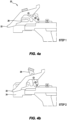
- Figure 4b shows step 2 of the six-step retraction process.
- the retractable probe 22 moves to the right which is moving rearward toward the housing relative to the apparatus 10.
- the lower work contact 24 remains stationary.
- Figure 4c shows step 3 of the six-step retraction process.
- the lower work contact 24 and probe 22 travel together in a rearward direction relative to the nose casting 34.
- Figure 4d shows step 4 of the six-step retraction process.
- the lower work contact 24 and probe 22 travel together until the lever 28 engages with the wedge 32 on the nose casting 34. At this point, the probe 22 will move further inwards.
- Figure 4e shows step 5 of the six-step retraction process.
- the probe 22 will keep moving until it hits an end of the slot 26 defined in the probe guides. This will then enable the probe 22 to rotate upwardly.
- Figure 4f shows step 6 of the six-step retraction process.
- the lever 28 will glide over the wedge 32 on the nose casting 34 and continue to slide along it.
- the probe 22 clears a raceway 36 for the fastener.
- the fasteners are stored in a coil formation in a fastener housing 38 of the coil feed 16.
- the probe 22 is configured to clear the raceway 36 of the apparatus 10, thereby making way for the fastener to be driven along the raceway 36 and into the substrate.
- the positive placement system 20 includes a mechanism (comprising the probe guides that each define the slot 26, lever 28, low-pressure spring 30 and wedge 32) to progressively move the probe 22 rearward then subsequently upward for avoiding damage to the substrate and for aligning the raceway 36 with a center of a hole for receiving the fastener.
- the present disclosure provides an apparatus 10 for driving fasteners, wherein the apparatus 10 includes a guidance system 18 for guiding the apparatus 10 relative to the substrate.
- the guidance system 18 is in the form of a positive placement system 20.
- the positive placement system 20 includes the retractable probe 22 configured to be placed on a receiving location of a substrate to be fastened for locating the apparatus 10 relative to the substrate.
- the retractable probe 22 is configured to subsequently retract to make way for the fastener to be driven at the receiving location.
- the retractable probe 22 is configured to clear the raceway 36 of the apparatus 10, thereby making way for the fastener to be driven.
- the positive placement system 20 includes a mechanism (comprising probe guides that each define a or the slot 26, lever 28, low-pressure spring 30, and wedge 32) to progressively move the probe 22 rearward then upward for avoiding damage to the substrate and for aligning the raceway 36 with a center of a hole for receiving the fastener.
- the guidance system and the speed provided by examples of the present disclosure may be beneficial over existing technologies.
- most existing coil nailers are pneumatically powered. Therefore, they need a compressor and long hoses.
- Coil nailers do not have flagging issues caused by paper collation used on straight magazine nailers.
- Examples of the present disclosure may be unique as they are an impulse tool, being combustion powered. This eliminates the need for long hoses and compressors, therefore being potentially easier to manoeuvre.
- Examples of the present disclosure may also have a positive placement nailer guidance system for face fixing. This will enable accurate nail placement and no damage to the substrate being applied.
- the positive placement nailer guidance system provides a positive location and the guidance system that is unique. Examples of the present disclosure locate the hole at the center and enable the probe to clear the raceway, without relying on a driven fastener contacting the probe to align the fastener to the hole.
- the mechanism of the guidance system results in a retractable action in two directions, being rearward and upward. These actions ensure that the probe will not damage the substrate material and that the raceway is aligned with a center of the hole.
- Various embodiments of the present disclosure may be in the form of a coil nailer that has a larger magazine capacity compared to a straight magazine (for example, 200 nails vs 40 nails).
- various known straight magazines have a paper collation that causes flagging (i.e., paper stuck to the material substrate). Paper flagging can cause moisture to sip into the material substrate, and an operator filling the holes will need to remove the paper before filling it.
- the coil can have a plastic collation that eliminates this issue.
- Figures 9 to 11 show an apparatus 10 for driving fasteners in accordance with another example embodiment of the present disclosure.
- the apparatus 10 shown in Figures 9 to 11 is generally similar to the apparatus 10 shown in Figures 1 to 8 , and like features are represented with like reference numerals.
- the apparatus of Figures 9 to 11 differs in the shape and configuration of the components of the guidance system 18. Specifically, the shape and configuration of the retractable probe 22 is different in that it has a more pronounced indentation 40 on a heel of a foot of the retractable probe 22 (as seen in Figures 11a to 11d ).
- the slots 26 are formed in the probe guides (not labelled) of a carrier 42 that has outwardly protruding guiding ears 44 that form an entry to the slots 26 so as to accommodate a crossbar 46 of the retractable probe 22, wherein the crossbar 46 rides in the slots 26.
- the slots 26 have opposed slot parts on either side of the carrier 42.
- the shaping of the lever 28 also differs from the first embodiment shown in Figures 1 to 8 .
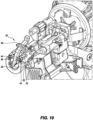
- Figure 9 shows a perspective view of the apparatus 10 for driving fasteners in accordance with this second embodiment of the present disclosure.
- Figure 10 shows a perspective view of the guidance system of Figure 9 , depicting detail of the retractable probe 22, the crossbar 46, the carrier 42, and the protruding guiding ears 44.
- Figures 11a to 11d show progressive movements of the guidance system 18 during operation and retraction of the probe 22.
- the retractable probe 22 is initially pushed rearwardly into the carrier 42 as the retractable probe 22 is pressed against a workpiece or substate (e.g., such as panelling) to be fastened.
- a workpiece or substate e.g., such as panelling
- Figure 11a to Figure 11b show that the retractable probe 22 is pushed inwardly into the carrier 42, with the retractable probe 22 sliding along the slots 26 by way of the crossbar 46, the lever 28 pivoting toward a vertical orientation to accommodate this movement.
- the crossbar 46 is pushed to abut against the rearmost extremities of the slots 26 and the carrier 42 is pushed rearwardly toward a main body of the fastening tool, a foot of the retractable probe 22 coming into contact with a forward angled surface of the wedge 32.
- the retractable probe 22 rides upwardly onto an upper surface of the wedge 32 such that the retractable probe 22 is brought wholly out of the raceway 36 so as to totally clear the raceway 36.
- this example embodiment of the present disclosure provides a positive placement system in which the retractable probe 22 is a true center probe, in that a tip of the retractable probe 22 is placed against the substrate (such as panelling) to be fastened at precisely the same point at which a fastener enters the substrate during driving of the fastener by the fastening tool.
- the positive placement system has a compact arrangement that provides improved accuracy and a reduced probability of damage to the substrate (such as panelling). As the retractable probe 22 totally clears the raceway 36 when retracted, this facilitates the avoidance of any loss of power which may otherwise be as a result of contact between a fastener travelling through the raceway and the retractable probe.
- example embodiments of the present disclosure can include an incorporated depth of drive so that there is a constant and consistent protrusion of the probe regardless of the depth of drive.
- the present disclosure may be particularly suitable where longer fasteners are used, where a harder substrate is used (requiring full power), and where decorative cladding is used such that accuracy is imperative.
- decorative cladding is in some instances unable to be repaired in this way such that decorative cladding needs to be discarded if it is damaged during fastening.
Landscapes
- Engineering & Computer Science (AREA)
- Mechanical Engineering (AREA)
- Chemical & Material Sciences (AREA)
- Combustion & Propulsion (AREA)
- Physics & Mathematics (AREA)
- Fluid Mechanics (AREA)
- Portable Nailing Machines And Staplers (AREA)
Abstract
An apparatus (10) for driving fasteners including a cylinder (12), a driving piston (14) arranged for driving a fastener from the apparatus (10) into a substrate, the piston (14) being arranged for reciprocating movement relative to the cylinder (12), a charge supply for feeding a charge to a combustion chamber of the cylinder (12) where the charge is combusted to drive movement of the piston (14) relative to the cylinder (12), a coil feed (16) of fasteners, and a guidance system (18) configured to guide the apparatus (10) relative to the substrate, the guidance system (18) including a positive placement system (20).
Description
- This application claims priority to and the benefit of
U.S. Provisional Patent Application Serial No. 63/501,920, filed May 12, 2023 - The present disclosure relates to an apparatus for driving fasteners. More particularly, various embodiments of the present disclosure relate to nail driving apparatus such as nail driving apparatus that are powered by combustion or pneumatically and fed with a coiled storage of fasteners or otherwise. The nail driving apparatus can be but is not limited to the type used for fastening cladding to a structure.
- It is known to fasten fibre cement cladding to a structure by drilling a hole through the fibre cement board's layers. The fibre cement cladding is then face fixed by hand hammering and is later filled with a filler compound. It is also known to fasten decorative cladding (such as natural timbers) by drilling a hole through the decorative cladding and by carefully hand hammering a fastener through the hole to avoid marring or otherwise damaging the timber. Any damage to the cladding, in particular where the cladding is decorative cladding, can result in the whole cladding board needing to be replaced. These known methods are time-consuming and inefficient, and hand hammering can sometimes damage the fibre cement board. Thus, there is a need for more efficient ways of fastening cladding with increased speed and decreased likelihood of damage.
- Various embodiments of the present disclosure provide an apparatus for driving fasteners that alleviates or at least ameliorates one or more disadvantages of existing methods and apparatuses used in fastening cladding.
- Various embodiments of the present disclosure provide an apparatus for driving fasteners that includes a housing, a cylinder in the housing, a driving piston in the housing and arranged for driving a fastener from the apparatus into a substrate, the piston being arranged for reciprocating movement in the housing relative to the cylinder, a charge supply in the housing for feeding a charge to a combustion chamber of the cylinder where the charge is combusted to drive movement of the piston relative to the cylinder. In various such embodiments, the apparatus includes a guidance system connected to the housing and configured to guide the apparatus relative to the substrate. In various such embodiments, the guidance system is in the form of a positive placement system. In various such embodiments, the positive placement system includes a retractable probe configured to be placed on a receiving location for locating the apparatus relative to the substrate, and wherein the retractable probe is configured to subsequently retract to make way for a fastener to be driven at the receiving location. In various such embodiments, the probe is configured to clear a raceway of the apparatus, thereby making way for the fastener to be driven. In various such embodiments, the positive placement system includes a mechanism configured to progressively move the probe rearward toward the housing and then upward for avoiding damage to the substrate and for aligning the raceway with a center of a hole for receiving the fastener. In various such embodiments, the fasteners are stored in a coil formation in a housing of the coil feed.
- Various other embodiments of the present disclosure provide an apparatus for driving fasteners, wherein the apparatus includes a guidance system connected to the housing and for guiding the apparatus relative to the substrate, wherein the guidance system is in the form of a positive placement system, the positive placement system includes a retractable probe configured to be placed on a receiving location of a substrate for locating the apparatus relative to the substrate, and wherein the retractable probe is configured to subsequently retract toward the housing to make way for the fastener to be driven at the receiving location. In various such embodiments, the probe is configured to clear a raceway of the apparatus, thereby making way for the fastener to be driven. In various such embodiments, the guidance system is configured to place a nail in an exact location where the probe once was at the time of initial abutment with the substrate. In various such embodiments, the positive placement system includes a mechanism configured to progressively move the probe rearward then upward for avoiding damage to the substrate and for aligning the raceway with a center of a hole for receiving the fastener.
-
-
Figure 1 is a perspective view of an apparatus for driving fasteners in accordance with one example embodiment of the present disclosure. -
Figure 2 is an exploded perspective view of the apparatus ofFigure 1 . -
Figure 3 is an enlarged fragmentary side view of a guidance system of the apparatus ofFigure 1 . -
Figures 4a to 4f are fragmentary side views of progressive movements of the guidance system during operation and retraction of a probe of the apparatus ofFigure 1 . -
Figure 5 is a fragmentary side view of the guidance system of the apparatus ofFigure 1 . -
Figure 6 is a fragmentary perspective view of the guidance system of the apparatus ofFigure 1 . -
Figure 7 is a fragmentary top view of the guidance system of the apparatus ofFigure 1 . -
Figure 8 is a fragmentary opposite side perspective view of the guidance system of the apparatus ofFigure 1 . -
Figure 9 is a perspective view of an apparatus for driving fasteners in accordance with another example embodiment of the present disclosure. -
Figure 10 is an enlarged fragmentary perspective view of the guidance system of the apparatus ofFigure 9 . -
Figures 11a to 11d are enlarged fragmentary side views of progressive movements of the guidance system of the apparatus ofFigure 9 during operation and retraction of the probe thereof. - While the systems, devices, and methods described herein may be embodied in various forms, the drawings show, and the specification describes certain exemplary and non-limiting embodiments. Not all components shown in the drawings and described in the specification may be required, and certain implementations may include additional, different, or fewer components. Variations in the arrangement and type of the components; the shapes, sizes, and materials of the components; and the manners of connections of the components may be made without departing from the spirit or scope of the claims. Unless otherwise indicated, any directions referred to in the specification reflect the orientations of the components shown in the corresponding drawings and do not limit the scope of the present disclosure. Further, terms that refer to mounting methods, such as mounted, connected, etc., are not intended to be limited to direct mounting methods but should be interpreted broadly to include indirect and operably mounted, connected, and like mounting methods. This specification is intended to be taken as a whole and interpreted in accordance with the principles of the present disclosure and as understood by one of ordinary skill in the art.
-
Figures 1 to 8 show anapparatus 10 for driving fasteners in accordance with one example embodiment of the present disclosure. Theapparatus 10 includes, among other conventional elements, a housing (not labelled), acylinder 12 and adriving piston 14 in the housing and arranged for driving a fastener (not shown) from theapparatus 10 into a substrate. Thepiston 14 is arranged for reciprocating movement relative to thecylinder 12. Theapparatus 10 also includes a charge supply in the housing for feeding a charge to a combustion chamber of thecylinder 12 where the charge is combusted to drive movement of thepiston 14 relative to thecylinder 12. Theapparatus 10 also includes acoil feed 16 connected to the housing and configured to hold and feed fasteners. - The
apparatus 10 includes aguidance system 18 connected to the housing and for guiding theapparatus 10 relative to the substrate. Theguidance system 18 is in the form of apositive placement system 20 for positively placing theapparatus 10 relative to the substrate such that the fastener being driven is accurately located relative to a desired receiving location (such as a hole). - The
positive placement system 20 includes aretractable probe 22 that is configured to be placed on a receiving location to be fastened for locating theapparatus 10 relative to the substrate. Theretractable probe 22 is configured to subsequently retract (such as shown inFigures 4a to 4f ) to make way for the fastener to be driven at the receiving location. - As best shown in
Figure 3 andFigures 4a to 4f , thepositive placement system 20 also includes alower work contact 24, probe guides (not labelled) that each define aslot 26, alever 28, a low-pressure spring 30, and awedge 32.Figure 3 also shows anose casting 34. Since bothslots 26 are identical, only oneslot 26 is described herein for brevity. -
Figure 4a showsstep 1 of a six-step retraction process of theretractable probe 22, as theapparatus 10 is brought into contact with a substrate and prepared for driving so as to drive a fastener into the substrate at a desired receiving location.Figure 4a shows theretractable probe 22 at its initial position. -
Figure 4b showsstep 2 of the six-step retraction process. In this step, after engaged in the hole, theretractable probe 22 moves to the right which is moving rearward toward the housing relative to theapparatus 10. The lower work contact 24 remains stationary. -
Figure 4c showsstep 3 of the six-step retraction process. In this step, when theapparatus 10 is actuated, the lower work contact 24 and probe 22 travel together in a rearward direction relative to thenose casting 34. -
Figure 4d showsstep 4 of the six-step retraction process. In this step, thelower work contact 24 and probe 22 travel together until thelever 28 engages with thewedge 32 on the nose casting 34. At this point, theprobe 22 will move further inwards. -
Figure 4e showsstep 5 of the six-step retraction process. In this step, theprobe 22 will keep moving until it hits an end of theslot 26 defined in the probe guides. This will then enable theprobe 22 to rotate upwardly. -
Figure 4f showsstep 6 of the six-step retraction process. In this step, as theapparatus 10 continues to be actuated, thelever 28 will glide over thewedge 32 on the nose casting 34 and continue to slide along it. At this stage, theprobe 22 clears araceway 36 for the fastener. - In this example embodiment of the
apparatus 10, the fasteners are stored in a coil formation in afastener housing 38 of thecoil feed 16. - Accordingly, as will be appreciated from the above description with reference to
Figures 4a to 4f , theprobe 22 is configured to clear theraceway 36 of theapparatus 10, thereby making way for the fastener to be driven along theraceway 36 and into the substrate. Thepositive placement system 20 includes a mechanism (comprising the probe guides that each define theslot 26,lever 28, low-pressure spring 30 and wedge 32) to progressively move theprobe 22 rearward then subsequently upward for avoiding damage to the substrate and for aligning theraceway 36 with a center of a hole for receiving the fastener. - As will further be appreciated from the above, the present disclosure provides an
apparatus 10 for driving fasteners, wherein theapparatus 10 includes aguidance system 18 for guiding theapparatus 10 relative to the substrate. Theguidance system 18 is in the form of apositive placement system 20. Thepositive placement system 20 includes theretractable probe 22 configured to be placed on a receiving location of a substrate to be fastened for locating theapparatus 10 relative to the substrate. Theretractable probe 22 is configured to subsequently retract to make way for the fastener to be driven at the receiving location. - The
retractable probe 22 is configured to clear theraceway 36 of theapparatus 10, thereby making way for the fastener to be driven. Thepositive placement system 20 includes a mechanism (comprising probe guides that each define a or theslot 26,lever 28, low-pressure spring 30, and wedge 32) to progressively move theprobe 22 rearward then upward for avoiding damage to the substrate and for aligning theraceway 36 with a center of a hole for receiving the fastener. - Advantageously, the guidance system and the speed provided by examples of the present disclosure may be beneficial over existing technologies. In particular, most existing coil nailers are pneumatically powered. Therefore, they need a compressor and long hoses. Coil nailers do not have flagging issues caused by paper collation used on straight magazine nailers. Examples of the present disclosure may be unique as they are an impulse tool, being combustion powered. This eliminates the need for long hoses and compressors, therefore being potentially easier to manoeuvre. Examples of the present disclosure may also have a positive placement nailer guidance system for face fixing. This will enable accurate nail placement and no damage to the substrate being applied.
- The positive placement nailer guidance system provides a positive location and the guidance system that is unique. Examples of the present disclosure locate the hole at the center and enable the probe to clear the raceway, without relying on a driven fastener contacting the probe to align the fastener to the hole. The mechanism of the guidance system results in a retractable action in two directions, being rearward and upward. These actions ensure that the probe will not damage the substrate material and that the raceway is aligned with a center of the hole.
- This overcomes issues with various known guidance systems, that if modified for a coil nailer, may damage the hole during deflection when the fastener is driven. Such damage would require more work for the person doing the filling on fibre cement cladding, increasing time and cost.
- Various embodiments of the present disclosure may be in the form of a coil nailer that has a larger magazine capacity compared to a straight magazine (for example, 200 nails vs 40 nails). Also, various known straight magazines have a paper collation that causes flagging (i.e., paper stuck to the material substrate). Paper flagging can cause moisture to sip into the material substrate, and an operator filling the holes will need to remove the paper before filling it. The coil can have a plastic collation that eliminates this issue.
- Although the drawings show the fasteners in the form of nails, it should be appreciated that, in other examples of the present disclosure, the guidance system may be used for other applications such as with fastener driving apparatus that uses screws for timber decking.
-
Figures 9 to 11 show anapparatus 10 for driving fasteners in accordance with another example embodiment of the present disclosure. Theapparatus 10 shown inFigures 9 to 11 is generally similar to theapparatus 10 shown inFigures 1 to 8 , and like features are represented with like reference numerals. The apparatus ofFigures 9 to 11 differs in the shape and configuration of the components of theguidance system 18. Specifically, the shape and configuration of theretractable probe 22 is different in that it has a morepronounced indentation 40 on a heel of a foot of the retractable probe 22 (as seen inFigures 11a to 11d ). In addition, theslots 26 are formed in the probe guides (not labelled) of acarrier 42 that has outwardly protruding guidingears 44 that form an entry to theslots 26 so as to accommodate acrossbar 46 of theretractable probe 22, wherein thecrossbar 46 rides in theslots 26. Theslots 26 have opposed slot parts on either side of thecarrier 42. The shaping of thelever 28 also differs from the first embodiment shown inFigures 1 to 8 . -
Figure 9 shows a perspective view of theapparatus 10 for driving fasteners in accordance with this second embodiment of the present disclosure.Figure 10 shows a perspective view of the guidance system ofFigure 9 , depicting detail of theretractable probe 22, thecrossbar 46, thecarrier 42, and the protruding guidingears 44.Figures 11a to 11d show progressive movements of theguidance system 18 during operation and retraction of theprobe 22. In particular, theretractable probe 22 is initially pushed rearwardly into thecarrier 42 as theretractable probe 22 is pressed against a workpiece or substate (e.g., such as panelling) to be fastened.Figure 11a to Figure 11b show that theretractable probe 22 is pushed inwardly into thecarrier 42, with theretractable probe 22 sliding along theslots 26 by way of thecrossbar 46, thelever 28 pivoting toward a vertical orientation to accommodate this movement. InFigure 11c , thecrossbar 46 is pushed to abut against the rearmost extremities of theslots 26 and thecarrier 42 is pushed rearwardly toward a main body of the fastening tool, a foot of theretractable probe 22 coming into contact with a forward angled surface of thewedge 32. At this point, theretractable probe 22 rides upwardly onto an upper surface of thewedge 32 such that theretractable probe 22 is brought wholly out of theraceway 36 so as to totally clear theraceway 36. - Advantageously, this example embodiment of the present disclosure provides a positive placement system in which the
retractable probe 22 is a true center probe, in that a tip of theretractable probe 22 is placed against the substrate (such as panelling) to be fastened at precisely the same point at which a fastener enters the substrate during driving of the fastener by the fastening tool. In addition, the positive placement system has a compact arrangement that provides improved accuracy and a reduced probability of damage to the substrate (such as panelling). As theretractable probe 22 totally clears theraceway 36 when retracted, this facilitates the avoidance of any loss of power which may otherwise be as a result of contact between a fastener travelling through the raceway and the retractable probe. Moreover, example embodiments of the present disclosure can include an incorporated depth of drive so that there is a constant and consistent protrusion of the probe regardless of the depth of drive. - The present disclosure may be particularly suitable where longer fasteners are used, where a harder substrate is used (requiring full power), and where decorative cladding is used such that accuracy is imperative. In comparison with other cladding which may be repaired by way of filler and painting, decorative cladding is in some instances unable to be repaired in this way such that decorative cladding needs to be discarded if it is damaged during fastening.
- While various embodiments of the present disclosure have been described above, it should be understood that they have been presented by way of example only, and not by way of limitation. It will be apparent to a person skilled in the relevant art that various changes in form and detail can be made therein without departing from the spirit and scope of the present disclosure. Thus, the present disclosure should not be limited by any of the above-described exemplary embodiments.
-
Apparatus for driving fasteners 10 Cylinder 12 Driving piston 14 Coil feed 16 Guidance system 18 Positive placement system 20 Retractable probe 22 Lower work contact 24 Slot 26 Lever 28 Low- pressure spring 30 Wedge 32 Nose casting 34 Raceway 36 Housing 38 Indentation 40 Carrier 42 Guiding ears 44 Crossbar 46
Claims (12)
- An apparatus for driving fasteners, the apparatus comprising:a cylinder having a combustion chamber;a driving piston configured to drive a fastener into a substrate, the piston moveable relative to the cylinder;a charge supply configured to feed a charge to the combustion chamber where the charge is combusted to drive movement of the piston relative to the cylinder;a coil feed configured to receive a plurality of fasteners including the fastener; anda guidance system configured to guide the apparatus relative to the substrate, the guidance system including a positive placement system.
- The apparatus of claim 1, wherein the positive placement system includes a retractable probe positionable at a receiving location relative to the substrate, and wherein the retractable probe is subsequently retractable to make way for the fastener to be driven at the receiving location.
- The apparatus of claim 2, wherein the fasteners are stored in a coil formation in a fastener housing of the coil feed.
- The apparatus of claim 2, wherein the retractable probe is positionable to clear a raceway of the apparatus, thereby making way for the fastener to be driven.
- The apparatus of claim 4, wherein the positive placement system includes a mechanism configured to align the raceway with a center of a hole configured to receive the fastener and to progressively move the retractable probe rearward then upward to avoid damage to the substrate.
- An apparatus for driving fasteners, the apparatus comprising:
a guidance system configured to guide the apparatus relative to a substrate, the guidance system including a positive placement system, the positive placement system including a retractable probe configured to be placed on a receiving location of a substrate to locate the apparatus relative to the substrate, and wherein the retractable probe is retractable to make way for the fastener to be driven at the receiving location. - The apparatus of claim 6, wherein the retractable probe is configured to clear a raceway of the apparatus, thereby making way for the fastener to be driven.
- The apparatus of claim 7, wherein the positive placement system includes a mechanism configured to align the raceway with a center of a hole configured to receive the fastener and to progressively move the retractable probe rearward then upward to avoid damage to the substrate.
- The apparatus of claim 8, wherein the guidance system is configured to guide a fastener to an exact location where the retractable probe was at a time of initial abutment with the substrate.
- The apparatus of claim 8, wherein the mechanism includes a ramped surface to assist raising of the retractable probe relative to the raceway as the retractable probe is moved rearwardly.
- The apparatus of claim 10, wherein said ramped surface include a wedge.
- The apparatus of claim 10, wherein said mechanism defines a slot, a lever, and a spring.
Applications Claiming Priority (2)
| Application Number | Priority Date | Filing Date | Title |
|---|---|---|---|
| US202363501920P | 2023-05-12 | 2023-05-12 | |
| US18/642,501 US20240375257A1 (en) | 2023-05-12 | 2024-04-22 | Apparatus for driving fasteners |
Publications (1)
| Publication Number | Publication Date |
|---|---|
| EP4461469A1 true EP4461469A1 (en) | 2024-11-13 |
Family
ID=91070210
Family Applications (1)
| Application Number | Title | Priority Date | Filing Date |
|---|---|---|---|
| EP24174991.0A Pending EP4461469A1 (en) | 2023-05-12 | 2024-05-08 | Apparatus for driving fasteners |
Country Status (4)
| Country | Link |
|---|---|
| US (1) | US20240375257A1 (en) |
| EP (1) | EP4461469A1 (en) |
| AU (1) | AU2024202870A1 (en) |
| CA (1) | CA3237259A1 (en) |
Citations (2)
| Publication number | Priority date | Publication date | Assignee | Title |
|---|---|---|---|---|
| US20070215665A1 (en) * | 2006-03-16 | 2007-09-20 | Yasuki Ohmori | Driving machine |
| US20080251559A1 (en) * | 2004-03-31 | 2008-10-16 | Jpf Works Co., Ltd. | Portable Type Fastener Driving Tool |
Family Cites Families (18)
| Publication number | Priority date | Publication date | Assignee | Title |
|---|---|---|---|---|
| US3854648A (en) * | 1972-10-04 | 1974-12-17 | G Inzoli | Air operated fastener driving tool, especially for tacks |
| US5238167A (en) * | 1992-10-09 | 1993-08-24 | Illinois Tool Works Inc. | Positioning mechanism for powered fastener-driving tool |
| US5452835A (en) * | 1994-08-01 | 1995-09-26 | Illinois Tool Works Inc. | Positioning mechanism for powered fastener-driving tool |
| JPH08229847A (en) * | 1995-02-28 | 1996-09-10 | Max Co Ltd | Attachment for box nailing machine |
| US6279808B1 (en) * | 1999-07-27 | 2001-08-28 | Mark E. Larsen | Nail guide mechanism for a nail gun |
| US6808101B2 (en) * | 2002-05-24 | 2004-10-26 | Illinois Tool Works Inc. | Framing tool with automatic fastener-size adjustment |
| US6789718B2 (en) * | 2002-09-17 | 2004-09-14 | Stanley Fastening Systems, L.P. | Nail placement device |
| US6578749B1 (en) * | 2002-12-06 | 2003-06-17 | Basso Industry Corp. | Nail guide device for a power nailer |
| JP4348995B2 (en) * | 2003-05-08 | 2009-10-21 | マックス株式会社 | Nail launch guide mechanism in nailing machine |
| JP4420205B2 (en) * | 2004-04-28 | 2010-02-24 | マックス株式会社 | Nail guide device for nailing machine |
| US7017790B1 (en) * | 2004-09-22 | 2006-03-28 | Wei-Chih Peng | Positioning device of a nail driver |
| FR2931380B1 (en) * | 2008-05-26 | 2010-08-20 | Prospection Et D Inventsions T | FLEXIBLE FIXING TOOL WITH FLEXIBLE BLADE |
| US9114516B2 (en) * | 2011-07-21 | 2015-08-25 | Illinois Tool Works Inc. | Portable combustion gas-powered tools with combustion chamber lockout system |
| US11077542B2 (en) * | 2013-10-31 | 2021-08-03 | Stanley Fastening Systems, L.P. | Metal connector adaptor for a fastening tool |
| US9527196B2 (en) * | 2013-11-06 | 2016-12-27 | Illinois Tool Works Inc. | Fastener driving tool with an automatic nose chamber guide member |
| US10350741B2 (en) * | 2015-11-02 | 2019-07-16 | Black & Decker Inc. | Powered nail driver with a nail placement assembly |
| US10987791B2 (en) * | 2019-04-01 | 2021-04-27 | Testo Industry Corp. | Probe assembly of a metal connector nailer |
| US12521855B2 (en) * | 2023-04-14 | 2026-01-13 | Illinois Tool Works Inc. | Fastener driving tool having a retractable probe assembly |
-
2024
- 2024-04-22 US US18/642,501 patent/US20240375257A1/en active Pending
- 2024-04-30 CA CA3237259A patent/CA3237259A1/en active Pending
- 2024-05-01 AU AU2024202870A patent/AU2024202870A1/en active Pending
- 2024-05-08 EP EP24174991.0A patent/EP4461469A1/en active Pending
Patent Citations (2)
| Publication number | Priority date | Publication date | Assignee | Title |
|---|---|---|---|---|
| US20080251559A1 (en) * | 2004-03-31 | 2008-10-16 | Jpf Works Co., Ltd. | Portable Type Fastener Driving Tool |
| US20070215665A1 (en) * | 2006-03-16 | 2007-09-20 | Yasuki Ohmori | Driving machine |
Also Published As
| Publication number | Publication date |
|---|---|
| CA3237259A1 (en) | 2025-06-17 |
| US20240375257A1 (en) | 2024-11-14 |
| AU2024202870A1 (en) | 2024-11-28 |
Similar Documents
| Publication | Publication Date | Title |
|---|---|---|
| CN111673853B (en) | Automatic nail gun for n-shaped nails | |
| AU2014347252B2 (en) | Fastener driving tool with an automatic nose chamber guide member | |
| US7882994B2 (en) | 45 degree adjustable adapter for flooring nailer | |
| JP4897789B2 (en) | Power nailing machine with block mechanism of driving blade | |
| US8931676B2 (en) | Nailer having mechanism for pre-positioning nail | |
| US20080041913A1 (en) | Pneumatic hand tool for inserting t-nuts | |
| WO2014182463A1 (en) | Fastening device for driving double-headed fasteners | |
| CN102039580B (en) | Fastener punching machine | |
| JP5076946B2 (en) | Nailer | |
| CN211805924U (en) | Continuous nail feeding gun | |
| US20240375257A1 (en) | Apparatus for driving fasteners | |
| US20130320062A1 (en) | Dual channel magazine lockout system | |
| US12036693B2 (en) | Board positioning system and method | |
| JP7623030B1 (en) | Nail driving device | |
| US9469022B2 (en) | Driving tools | |
| JP3910619B2 (en) | Automatic nailing device for game board | |
| CN218488284U (en) | Device for penetrating pin on product | |
| JP2549592Y2 (en) | Nail escape device for nailing machine for loose nails | |
| JPS597015Y2 (en) | Temporary nail driving guide with prismatic elastic body | |
| JPS64296Y2 (en) | ||
| JP4139528B2 (en) | Fixing device feeding device for fixing device driving machine | |
| JP2001062755A (en) | Nail feeding mechanism of nail driving machine for connected nail | |
| KR20250023959A (en) | Fastener support tool, connecting fastener, and manufacturing method of fastener support tool | |
| JP3938778B2 (en) | Automatic nailing device for game board | |
| JPS6216293Y2 (en) |
Legal Events
| Date | Code | Title | Description |
|---|---|---|---|
| PUAI | Public reference made under article 153(3) epc to a published international application that has entered the european phase |
Free format text: ORIGINAL CODE: 0009012 |
|
| STAA | Information on the status of an ep patent application or granted ep patent |
Free format text: STATUS: THE APPLICATION HAS BEEN PUBLISHED |
|
| AK | Designated contracting states |
Kind code of ref document: A1 Designated state(s): AL AT BE BG CH CY CZ DE DK EE ES FI FR GB GR HR HU IE IS IT LI LT LU LV MC ME MK MT NL NO PL PT RO RS SE SI SK SM TR |
|
| STAA | Information on the status of an ep patent application or granted ep patent |
Free format text: STATUS: REQUEST FOR EXAMINATION WAS MADE |
|
| 17P | Request for examination filed |
Effective date: 20250512 |