EP4461430A1 - Press-forming apparatus and method for producing press-formed article - Google Patents
Press-forming apparatus and method for producing press-formed article Download PDFInfo
- Publication number
- EP4461430A1 EP4461430A1 EP23752750.2A EP23752750A EP4461430A1 EP 4461430 A1 EP4461430 A1 EP 4461430A1 EP 23752750 A EP23752750 A EP 23752750A EP 4461430 A1 EP4461430 A1 EP 4461430A1
- Authority
- EP
- European Patent Office
- Prior art keywords
- press
- protrusion
- punch
- forming apparatus
- punch shoulder
- Prior art date
- Legal status (The legal status is an assumption and is not a legal conclusion. Google has not performed a legal analysis and makes no representation as to the accuracy of the status listed.)
- Pending
Links
Images






Classifications
-
- B—PERFORMING OPERATIONS; TRANSPORTING
- B21—MECHANICAL METAL-WORKING WITHOUT ESSENTIALLY REMOVING MATERIAL; PUNCHING METAL
- B21D—WORKING OR PROCESSING OF SHEET METAL OR METAL TUBES, RODS OR PROFILES WITHOUT ESSENTIALLY REMOVING MATERIAL; PUNCHING METAL
- B21D22/00—Shaping without cutting, by stamping, spinning, or deep-drawing
- B21D22/20—Deep-drawing
- B21D22/22—Deep-drawing with devices for holding the edge of the blanks
-
- B—PERFORMING OPERATIONS; TRANSPORTING
- B21—MECHANICAL METAL-WORKING WITHOUT ESSENTIALLY REMOVING MATERIAL; PUNCHING METAL
- B21D—WORKING OR PROCESSING OF SHEET METAL OR METAL TUBES, RODS OR PROFILES WITHOUT ESSENTIALLY REMOVING MATERIAL; PUNCHING METAL
- B21D22/00—Shaping without cutting, by stamping, spinning, or deep-drawing
- B21D22/20—Deep-drawing
- B21D22/30—Deep-drawing to finish articles formed by deep-drawing
-
- B—PERFORMING OPERATIONS; TRANSPORTING
- B21—MECHANICAL METAL-WORKING WITHOUT ESSENTIALLY REMOVING MATERIAL; PUNCHING METAL
- B21D—WORKING OR PROCESSING OF SHEET METAL OR METAL TUBES, RODS OR PROFILES WITHOUT ESSENTIALLY REMOVING MATERIAL; PUNCHING METAL
- B21D37/00—Tools as parts of machines covered by this subclass
- B21D37/08—Dies with different parts for several steps in a process
Definitions
- the present invention relates to a press-forming apparatus and a method for producing a press-formed article.
- Patent Document 1 Japanese Patent No. 2560416
- the present invention has an object to provide a press-forming apparatus capable of suppressing a problem occurring in a curved portion of a formed article, and a method for producing a press-formed article.
- the present invention proposes the following means.
- the press-forming apparatus and the method for producing a press-formed article of the present invention it is possible to suppress a problem occurring in a curved portion of a formed article.
- FIGS. 1 to 24 one embodiment of a press-forming apparatus and a method for producing a press-formed article according to the present invention will be described with reference to FIGS. 1 to 24 .
- annular component that is manufactured by the press-forming apparatus and the method for producing a press-formed article, and a press-formed article that is an intermediate formed product which is formed during the manufacturing of the annular component will be described.
- a press-formed article 100A includes a top sheet 10, a peripheral wall 20, and a flange 30.
- the press-formed article 100A has a deep dish shape.
- the top sheet 10 has a polygonal shape with rounded corners when viewed in a thickness direction of the top sheet 10.
- the top sheet 10 has a rectangular shape with rounded corners in which corners of a rectangular shape having a long side and a short side are rounded. That is, there is a long side or a short side between two rounded corners.
- a protrusion portion 11 is formed on the top sheet 10.
- two protrusion portions 11 are formed on the top sheet 10.
- Each protrusion portion 11 protrudes in a thickness direction (protrusion direction) D1 of a first surface 10a side of the top sheet 10.
- the surface of the top sheet 10 on the side opposite to the first surface 10a is referred to as a second surface 10b. That is, the outer side surface of the deep dish shape of the top sheet 10 is the first surface 10a, and the inner side surface of the deep dish shape of the top sheet 10 is the second surface 10b.
- Each protrusion portion 11 is a groove extending in a direction along the long side when viewed from the second surface 10b of the top sheet 10.
- the two protrusion portions 11 are disposed to be spaced apart from each other in a direction along the short side of the top sheet 10.
- the two protrusion portions 11 are disposed in a middle portion of the top sheet 10 when viewed in the thickness direction of the top sheet 10. That is, a flat surface due to the second surface 10b is formed between each protrusion portion 11 and the edge of the second surface 10b.
- the peripheral wall 20 protrudes in a counter-protrusion direction D2 opposite to the protrusion direction D1 from the edge of the top sheet 10.
- the peripheral wall 20 is formed over the whole circumference of the edge of the top sheet 10.
- the angle formed by the second surface 10b of the top sheet 10 and the peripheral wall 20 may be an obtuse angle or may be a right angle.
- the flange 30 protrudes from an end portion of the peripheral wall 20 in the counter-protrusion direction D2 toward the outside of the peripheral wall 20.
- the flange 30 is formed over the whole circumference of the peripheral wall 20.
- the shape of the press-formed article 100A is not limited to this.
- the press-formed article 100A does not need to have the flange 30.
- an annular component 100 is manufactured by removing the middle portion of the top sheet 10, which includes the two protrusion portions 11 in the top sheet 10, from the press-formed article 100A.
- a through-hole 12 is formed in the top sheet 10 from which the middle portion is removed. The through-hole 12 penetrates the top sheet 10 in the thickness direction of the top sheet 10.
- the annular component 100 can be applied to a frame such as a window frame of a vehicle or a component configuring an A-pillar.
- a press-forming apparatus 200 includes a punch 210, a die 220, a blank holder 230, and a biasing member 240.
- the biasing member 240 is not shown.
- the biasing member 240 may be a member such as a hydraulic mechanism that is used in a conventional press-forming apparatus.
- FIG. 5 is a sectional view taken along cutting-plane line A5-A5 in FIG. 4 .
- the punch 210 includes a base 211, a punch portion 212, and a protrusion 213.
- the punch portion 212 and the protrusion 213 are essential.
- the base 211 does not need to be provided.
- the biasing member 240 is supported on a separate foundation from the punch 210.
- the base 211 is formed in a flat plate shape.
- the punch portion 212 is formed in a shape corresponding to the top sheet 10 and the peripheral wall 20 of the press-formed article 100A.
- the punch portion 212 protrudes from a middle portion of a surface 211a of the base 211 facing the thickness direction of the base 211.
- the punch portion 212 is formed in a tapered shape in which a cross-sectional area orthogonal to the protrusion direction is narrowed as a protruding length increases.
- the punch portion 212 is formed in a truncated square pyramid shape with rounded corners.
- the punch portion 212 has a rectangular shape with rounded corners, in which the corners of a rectangular shape having a long side and a short side are rounded when viewed in the protrusion direction, to correspond to the top sheet 10 of the press-formed article 100A.
- the pressing direction is a direction in which the die and the punch are moved toward an object to be formed during press forming.
- the pressing direction is E2 in FIGS. 4 and 5 .
- the pressing direction is E1 in FIGS. 4 and 5 .
- the pressing direction means the axial directions of E1 and E2, and the direction of the pressing direction is not considered.
- the direction from the punch 210 toward the die 220 in the pressing direction is referred to as a pressing direction E1 and the direction from the die 220 toward the punch 210 in the pressing direction is referred to as a counter-pressing direction E2.
- a direction (hereinafter, referred to as a short side direction) F along a short side of the punch portion 212, and a direction (hereinafter, referred to as a long side direction, an extension direction) G along a long side of the punch portion 212 are orthogonal to the pressing direction E1.
- the punch portion 212 has a convex shape toward the die 220.
- the punch portion 212 is formed with a top surface 212a, a side surface 212b, and a punch shoulder 212c.
- the top surface 212a is a tip end surface of the punch portion 212 in the pressing direction E1.
- the side surface 212b is a side surface of the punch portion 212 with respect to the pressing direction E1.
- the side surface 212b is formed over the whole circumference around the edge of the top surface 212a.
- the punch shoulder 212c is disposed (at a connection portion) between the top surface 212a and the side surface 212b of the punch portion 212. In other words, the top surface 212a and the side surface 212b are connected to each other via the punch shoulder 212c.
- the punch shoulder 212c is a ridge between the top surface 212a and the side surface 212b.
- the punch shoulder 212c includes punch shoulder straight portions 212c1 and 212c2 and a punch shoulder curved portion 212c3.
- the punch shoulder straight portions 212c1 and 212c2 extend with a radius of curvature of 500 mm or more.
- the punch shoulder straight portion 212c1 extends along the short side direction F.
- the punch shoulder straight portion 212c2 extends along the long side direction G.
- the punch shoulder curved portion 212c3 extends with a radius of curvature of less than 500 mm.
- the punch shoulder curved portion 212c3 is connected to an end portion in the short side direction F of the punch shoulder straight portion 212c1 and an end portion in the long side direction G of the punch shoulder straight portion 212c2.
- the center angle of the punch shoulder curved portion 212c3 as viewed from the pressing direction E1 (viewed along the pressing direction E1) is about 90°.
- the punch 210 has two protrusions 213 corresponding to the two protrusion portions 11 of the press-formed article 100A.
- the two protrusions 213 protrude in the pressing direction E1 from the top surface 212a of the punch portion 212. That is, the top surface 212a of the punch portion 212 has two protrusions 213 protruding in the pressing direction E1.
- the protrusion 213 protrudes toward the die 220. This does not change regardless of whether the pressing direction that is defined by the moving direction of the die and the punch during press forming is the pressing direction E1 or the counter-pressing direction E2.
- Each protrusion 213 extends along the long side direction G.
- the two protrusions 213 are disposed to be spaced apart from each other in the short side direction F.
- Each protrusion 213 is not formed on the edge of the top surface 212a of the punch portion 212, and is formed at the middle portion of the top surface 212a. That is, a flat surface due to the top surface 212a is formed between the protrusion 213 and the edge of the top surface 212a.
- a plane passing through the end of the punch shoulder straight portion 212c1 and orthogonal to the punch shoulder straight portion 212c1 is defined as a plane P5.
- a plane passing through the end of the punch shoulder straight portion 212c2 and orthogonal to the punch shoulder straight portion 212c2 is defined as a plane P6.
- the planes P5 and P6 are also planes passing through the end of the punch shoulder curved portion 212c3 and orthogonal to the punch shoulder curved portion 212c3.
- planes that coincide with the planes P5 and P6 are defined as planes P5A and P6A, as shown in FIG. 2 .
- a portion of the flange 30 sandwiched between the two planes P5A is defined as a flange straight portion 33a.
- a portion of the flange 30 sandwiched between the two planes P6A is defined as a flange straight portion 33b.
- a portion of the flange 30 sandwiched by the planes P5A and P6A is defined as a flange curved portion 33c.
- the interval in the long side direction G between the tip end on a first side G1 in the long side direction G of the protrusion 213 and the center of the punch shoulder straight portion 212c2 is defined as an interval L1.
- the interval L1 is preferably 40% or more of the length in the long side direction G of the punch shoulder straight portion 212c2.
- a first straight line M1 passing through (a connection portion) between the punch shoulder straight portion 212c2 and the punch shoulder curved portion 212c3 and perpendicular to the long side direction G is defined.
- the first straight line M1 is included in the plane P6.
- FIG. 7 shows a cross section passing through the protrusion 213 and perpendicular to the long side direction G.
- the direction perpendicular to the pressing direction E1 and along this cross section is the short side direction F.
- the length of the surface of the protrusion 213 is preferably larger than 1.2 times the width of the protrusion 213 in the short side direction F.
- the cross section along each of the pressing direction E1 and the long side direction G is a cross section perpendicular to the short side direction F.
- FIG. 8 shows a cross section passing through the protrusion 213 and perpendicular to the short side direction F.
- an angle ⁇ 1 formed by the surface of the tip end portion in the long side direction G of the protrusion 213 and the pressing direction E1 is preferably 30° or larger.
- the centroid of the top surface 212a of the punch portion 212 is preferably located inside a top portion of 20% or more of the height in the pressing direction E1 of the protrusion 213.
- the centroid of the top surface 212a referred to herein means the centroid of the top surface 212a when the protrusion 213 is not formed on the top surface 212a.
- the top portion of 20% or more of the height in the pressing direction E1 of the protrusion 213 means the range of 20% of the height in the pressing direction E1 of the protrusion 213 in the counter-pressing direction E2 from the end of the protrusion 213 in the pressing direction E1.
- an angle ⁇ 2 formed by the two punch shoulder straight portions 212c1 and 212c2 on both sides of the punch shoulder curved portion 212c3 shown in FIG. 6 is an acute angle, so that the effects of the present disclosure are likely to be exhibited.
- the die 220 is a lump of metal.
- the surface of the die 220 facing the counter-pressing direction E2 is a sheet pressing surface 220a.
- a die hole 211 which is recessed in the shape of the punch portion 212 is formed on the sheet pressing surface 220a of the die 220.
- a bottom surface 221a of the die hole 221 has a shape corresponding to the top surface 212a of the punch 210.
- the bottom surface 221a has a shape in which the unevenness of the top surface 212a is inverted in the pressing direction E1.
- the bottom surface 221a has a shape in which the top surface 212a is increased by an amount corresponding to the sheet thickness of a metal sheet S (described later) along the top surface 212a to the outside of the edge of the top surface 212a.
- Two recessed portions 222 corresponding to the two protrusions 213 of the punch 210 are formed on the bottom surface 221a of the die hole 221.
- Each recessed portion 222 extends along the long side direction G.
- the two recessed portions 222 are disposed to be spaced apart from each other in the short side direction F.
- the blank holder 230 is formed in a flat plate shape.
- a through-hole 231 corresponding to the punch portion 212 of the punch 210 is formed in the center portion of the blank holder 230.
- the through-hole 231 penetrates the blank holder 230 in the pressing direction E1.
- the punch portion 212 can be inserted into the through-hole 231 in the pressing direction E1.
- the blank holder 230 is disposed between the base 211 of the punch 210 and the sheet pressing surface 220a of the die 220.
- the biasing member 240 that supports the blank holder 230 from the counter-pressing direction E2 is supported on a foundation (not shown).
- the blank holder 230 is disposed to face the sheet pressing surface 220a of the die 220.
- the metal sheet S that is a material for forming the press-formed article 100A can be clamped by the die 220 and the blank holder 230.
- the press-forming apparatus 200 includes a plurality of biasing members 240.
- the biasing member 240 is a spring.
- Each of the biasing members 240 is fixed to the surface 211a of the base 211 such that the punch portion 212 is interposed between the biasing members 240 in the short side direction F.
- Each biasing member 240 extends in the pressing direction E1 from the base 211.
- Each biasing member 240 is fixed to the surface facing the counter-pressing direction E2 of the blank holder 230.
- the biasing member 240 is not limited to a spring, and may be a hydraulic cylinder or the like.
- the press-forming apparatus 200 does not need to include the biasing member 240.
- the blank holder 230 does not move, and the die 220 moves toward the blank holder 230 to clamp the metal sheet S. Thereafter, the punch 210 moves in the pressing direction E1 to perform press forming.
- FIG. 9 is a flowchart showing a method for producing a press-formed article S1 according to one embodiment of the present invention.
- the tensile strength of the metal sheet S that is used in the method for producing a press-formed article S1 is 980 MPa or more.
- step S5 the metal sheet S is clamped by the die 220 and the blank holder 230 with the biasing force of the biasing member 240 (hereinafter, referred to as a clamping step S5).
- the process proceeds to step S6.
- step S6 as shown in FIGS. 10 and 11 , the punch 210 is moved in the pressing direction E1 with respect to the die 220 to draw the metal sheet S with the press-forming apparatus 200 (hereinafter, referred to as a drawing step S6).
- FIG. 10 is a sectional view during the drawing step S6, and
- FIG. 11 is a sectional view in the last stage of the drawing step S6.
- the metal sheet S is stretched in the pressing direction E1 by the two protrusions 213.
- the top sheet 10, the two protrusion portions 11, the peripheral wall 20, and the flange 30 are simultaneously formed on the metal sheet S, and the press-formed article 100Ais manufactured.
- the two protrusion portions 11 are formed by the two protrusions 213 of the punch 210 and the two recessed portions 222 of the die 220.
- step S6 When the drawing step S6 is ended, the process proceeds to step S7.
- step S7 the middle portion (the portions formed in the metal sheet S by the two protrusions 213) of the top sheet 10 is removed from the press-formed article 100A by a press-forming apparatus or the like different from the press-forming apparatus 200 (hereinafter, referred to as a removal step S7).
- the removal step S7 the two protrusion portions 11 in the press-formed article 100A are removed.
- the removal step S7 is a step that is performed after the drawing step S6.
- the method for producing a press-formed article S1 includes the clamping step S5, the drawing step S6, and the removal step S7.
- the removal step S7 does not need to be performed in the method for producing a press-formed article.
- FIG. 12 shows a process in which the metal sheet S is drawn to the comparative example press-formed article 100B.
- the metal sheet S is shown with hatching to make it easier to understand deformation.
- the portion that is formed by the punch shoulder 212c of the punch portion 212 at the connection portion between the top sheet 10 and the peripheral wall 20 is referred to as a shoulder 14.
- the shoulder 14 is a convex ridge.
- portions that are formed by the punch shoulder straight portions 212c1 and 212c2 and the punch shoulder curved portion 212c3 of the punch shoulder 212c are referred to as shoulder straight portions 14a1 and 14a2 and a shoulder curved portion 14a3, respectively.
- the connection portion between the peripheral wall 20 and the flange 30 is referred to as a dent 31.
- the dent 31 is a concave ridge.
- portions around an outer peripheral edge Se of the metal sheet S corresponding to the shoulder straight portions 14a1 and 14a2 and the shoulder curved portion 14a3 are referred to as dent straight portions 31a1 and 31a2 and a dent curved portion 31a3.
- the terminus of a linear arrows B1 represents the position before drawing of a certain point on an edge of each of the press-formed articles 100A and 100B, and the tip end of the linear arrow B1 represents the position to which a certain point on the edge of each of the press-formed articles 100A and 100B after forming are moved.
- the outer peripheral edge Se of the metal sheet S indicated by a two-dot chain line moves (displaces) toward the die hole 221 at any position of the outer peripheral edge Se, as indicated by the linear arrow.
- an element a of the metal sheet S on the dent curved portion 31a3 is compressed along the dent curved portion 3 1a3, as indicated by a white arrow.
- an element ⁇ of the metal sheet S on the shoulder curved portion 14a3 is pulled along the shoulder curved portion 14a3, as indicated by a white arrow, and further pulled toward a center direction of the top sheet 10 from the flange 30.
- the element ⁇ is subjected to shrink flanging.
- the element ⁇ is subjected to stretch forming.
- the shrink flanging referred to herein means forming in which a material such as a metal sheet is shrunk in an extension direction of a ridge when the material is drawn toward the ridge.
- the stretch flanging means forming in which a material is stretched in the extension direction of the ridge when the material is drawn toward the ridge.
- FIG. 13 shows forming of the press-formed article 100A of the present disclosure.
- white arrows B4 to B6 indicate changes in the inflow amount of the metal sheet S from FIG. 12 .
- the white arrow B4 means that the inflow of the metal sheet S from the flange 30 toward the top sheet 10 increases because there is the protrusion portion 11 extending in the direction along the long side (the direction along the shoulder straight portion 14a2).
- the white arrow B5 means that the flange curved portion 33c is stretched due to the influence of the inflow of the white arrow B4.
- the white arrow B6 adjacent to the element ⁇ means that the shrink flanging of the element ⁇ is relaxed due to the influence of the stretching of the flange curved portion 33c.
- the inflow of the metal sheet S occurs in the initial stage of the stretch flanging or shrink flanging.
- an outflow that pulls the curved portion of the outer peripheral edge Se of the metal sheet S also occurs.
- the occurrence of wrinkles due to the shrink flanging of the element ⁇ is suppressed due to the outflow of the curved portion of the outer peripheral edge Se of the metal sheet S.
- the deformation resistance to the shrink flanging of the element a is relaxed.
- the inflow amount of the material toward the element ⁇ from the element ⁇ increases. As a result, the occurrence of cracking due to the stretch flanging of the element ⁇ is suppressed.
- the punch 210 is formed with a recessed portion 214 instead of the protrusion 213, and the die 220 is formed with a protrusion 223 instead of the recessed portion 222.
- a recessed portion is formed in the press-formed article 100A by the recessed portion 214 of the punch 210 and the protrusion 223 of the die 220.
- an inflow of the metal sheet S occurs at the final stage of the stretch flanging or the shrink flanging. That is, the same stretch flanging and shrink flanging as those in a case where the recessed portion 214 and the protrusion 223 are not provided occur until the final stage of the forming of the press-formed article. Further, in the final stage of the forming, since the metal sheet S is restrained by the punch 210 and the die 220, a large inflow of the metal sheet S does not occur. Instead, the metal sheet S in the vicinity of the recessed portion 214 is stretched.
- the distance from a center 10c of the top sheet 10 in the direction along the long side to a tip end 11a on the first side of the protrusion portion 11 in the direction along the long side is defined as a distance De.
- the distance from the center 10c of the top sheet 10 to a boundary P1 between the shoulder straight portion 14a2 and the shoulder curved portion 14a3 is defined as a distance Ds.
- a sheet thickness before drawing at a predetermined portion of the metal sheet S (the press-formed article 100A) is defined as tb, and a sheet thickness after drawing is defined as ta.
- a sheet thickness reduction rate r of the predetermined portion is defined as (tb - ta)/tb.
- the sheet thickness reduction rate r is a positive value, this means that the sheet thickness of the predetermined portion decreases, and in a case where the sheet thickness reduction rate r is a negative value, this means that the sheet thickness of the predetermined portion increases.
- a portion where the sheet thickness reduction rate r is a positive value means that it is subjected to stretch flanging
- a portion where the sheet thickness reduction rate r is a negative value means that it is subjected to shrink flanging.
- the sheet thickness reduction rate r of the press-formed article 100A is defined as a sheet thickness reduction rate ra
- the sheet thickness reduction rate r of the comparative example press-formed article 100B is defined as a sheet thickness reduction rate rb
- the sheet thickness reduction rate ratio is defined as (rb - ra)/rb.
- the depth of the protrusion portion 11 in the press-formed article 100A was set to 10 mm.
- a drawing depth by drawing that is, the distance from the flange 30 to the second surface 10b of the top sheet 10 was set to 50 mm.
- the radius of curvature of the shoulder curved portion 14a3 was set to 90 mm.
- the angle formed by the second surface 10b of the top sheet 10 and the peripheral wall 20 was set to 100°.
- the sheet thickness reduction rate ratios were measured at points t1 to t4 in the press-formed article 100A shown in FIG. 2 .
- FIG. 14 is a diagram showing a relationship between the value of (De/Ds) and the sheet thickness reduction rate ratio.
- FIG. 7 shows a cross section of the protrusion portion 11 orthogonal to the direction along the long side, in which the depth Hp in the protrusion portion 11 is the maximum.
- the extension length of the surface of the protrusion portion 11 in the cross section is defined as a promotion line length Lp.
- the length between both ends of the cross section of the protrusion portion 11 is defined as a reference line length Ls.
- the ratio of the promotion line length Lp to the reference line length Ls is defined as a line length ratio (Lp/Ls).
- FIG. 15 shows a change in sheet thickness reduction rate ratio with respect to the line length ratio (Lp/Ls). From FIG. 15 , it is found that in a case where the line length ratio (Lp/Ls) is more than 1.20, the sheet thickness reduction rate ratio increases. That is, in a case where the line length ratio (Lp/Ls) is more than 1.20, a change in sheet thickness before and after the drawing is relaxed.
- the line length ratio (Lp/Ls) of the protrusion portion 11 of the press-formed article 100A is more than 1.20.
- the ratio of the promotion line length Lp of the protrusion portion 11 to the reference line length Ls is more than 1.20.
- FIG. 16 shows a change in sheet thickness reduction rate ratio with respect to the depth Hp of the protrusion portion 11.
- the protrusion portion 11 has a cross section in which the depth Hp is 10 mm or more.
- the press-formed article 100A is manufactured by the punch 210, the die 220, and the blank holder 230. At that time, a portion adjacent to the punch shoulder curved portion 212c3 in the top surface 212a convexly protrudes toward the outside of the top surface 212a, and there are two protrusions 213 on the top surface 212a of the punch portion 212. Therefore, for example, when the metal sheet S is subjected to drawing, the two protrusions 213 of the punch 210 pull the portions of the metal sheet S which serve as the curved portions 14a3 and 31a3 of the press-formed article 100A.
- the press-formed article 100A is manufactured by the press-forming apparatus 200, it is possible to suppress a problem such as wrinkles or cracking occurring in the curved portions 14a3 and 31a3 of the press-formed article 100A.
- the angle ⁇ 1 formed by the surface of the tip end portion in the long side direction G of the protrusion 213 and the pressing direction E1 is 30° or larger. In this case, it is possible to suppress the occurrence of local strain due to the forming itself of the protrusion portion 11, and to make the metal sheet S smoothly flow along the top sheet 10 from the flange curved portion 33c toward the flange straight portions 33a and 33b. Therefore, it is possible to manufacture the annular component 100 in which the occurrence of a problem in the curved portions 14a3 and 31a3 is suppressed.
- the centroid of the top surface 212a of the punch portion 212 is located inside the top portion of 20% or more of the height in the pressing direction E1 of the protrusion 213.
- the material inflow amount can be increased over the whole circumference of the annular ridge 213c.
- the clamping step S5 and the drawing step S6 are performed.
- the tensile strength of the metal sheet S is 980 MPa or more, since the problem due to the change in sheet thickness due to the press forming is manifested, the effect of the present disclosure is further manifested.
- the middle portion of the top sheet 10 can be removed from the press-formed article 100Ato manufacture the annular component 100.
- a press-formed article 101A of a first modification example includes one protrusion portion 11 with respect to the two protrusion portions 11 in each configuration of the press-formed article 100A of the present embodiment.
- a press-formed article 101B of a second modification example includes three protrusion portions 11 with respect to the two protrusion portions 11 in each configuration of the press-formed article 100A of the present embodiment.
- the three protrusion portions 11 are disposed at intervals in the direction along the short side.
- a press-formed article 101C of a third modification example includes four protrusion portions 11 with respect to the two protrusion portions 11 in each configuration of the press-formed article 100A of the present embodiment.
- One set of protrusion portions 11 composed of two protrusion portions 11 among the four protrusion portions 11 are arranged side by side to be spaced apart from each other in the direction along the long side.
- Two sets of protrusion portions 11 are arranged side by side to be spaced apart from each other in the direction along the short side.
- the protrusion portion 11 when the protrusion portion 11 extends along the shoulder straight portion 14a2 from a portion adjacent to the shoulder curved portion 14a3 in the shoulder straight portions 14a2 adjacent to the outside of the top sheet 10, the effect of relaxing the shrink flanging of the flange curved portion 33c is obtained. At this time, the protrusion portion 11 does not need to necessarily extend to the center portion of the shoulder straight portion 14a2.
- a top sheet 40 of a press-formed article 101D of a fourth modification example has a triangular shape with rounded corners when viewed in the thickness direction of the top sheet 40.
- the protrusion portion 41 is formed on the top sheet 40.
- the protrusion portion 41 has a triangular shape with rounded corners similar to the shape of the top sheet 40 when viewed in the thickness direction of the top sheet 40.
- a top sheet 45 of an annular component 102A of the first modification example has an elliptical shape when viewed in the thickness direction of the top sheet 45.
- a through-hole 46 penetrating the top sheet 45 in the thickness direction of the top sheet 45 is formed in the top sheet 45.
- a top sheet 50 of an annular component 102B of the second modification example has a triangular shape with rounded corners when viewed in the thickness direction of the top sheet 50.
- a top sheet 55 of an annular component 102C of the third modification example has a pentagon shape when viewed in the thickness direction of the top sheet 55.
Landscapes
- Engineering & Computer Science (AREA)
- Mechanical Engineering (AREA)
- Shaping Metal By Deep-Drawing, Or The Like (AREA)
Abstract
Description
- The present invention relates to a press-forming apparatus and a method for producing a press-formed article.
- This application claims the right of priority based on
Japanese Patent Application No. 2022-019563 filed with the Japan Patent Office on February 10, 2022 - In the related art, there is a press-forming apparatus that forms a formed article having a desired shape by drawing in which in a state where end portions of a material having a thin thickness are clamped with high strength, the material is sandwiched and pressed between a die and a punch (refer to, for example, Patent Document 1).
- [Patent Document 1]
Japanese Patent No. 2560416 - However, in the drawing by the press-forming apparatus of the related art, there is a concern that a problem such as wrinkles or cracking may occur in the vicinity of a curved portion of a formed article.
- In view of the problem in the related art described above, the present invention has an object to provide a press-forming apparatus capable of suppressing a problem occurring in a curved portion of a formed article, and a method for producing a press-formed article.
- In order to solve the above problem, the present invention proposes the following means.
- (1)
Aspect 1 of the present invention is a press-forming apparatus including; a punch; a die; and a blank holder, in which the punch has a top surface, a side surface, and a punch shoulder disposed between the top surface and the side surface, the punch shoulder has a punch shoulder straight portion extending with a radius of curvature of 500 mm or more and a punch shoulder curved portion extending with a radius of curvature of less than 500 mm, a portion adjacent to the punch shoulder curved portion in the top surface convexly protrudes toward an outside of the top surface, the top surface has a protrusion protruding in a pressing direction, the protrusion extends along an extension direction in which the punch shoulder straight portion extends, a bottom surface of a die hole of the die has a shape corresponding to the top surface, and the blank holder is disposed to face a sheet pressing surface of the die. - (2) Aspect 2 of the present invention may be the press-forming apparatus according to the above (1), in which when viewed from the pressing direction, an interval in the extension direction between a tip end of the protrusion in the extension direction and a center of the punch shoulder straight portion is 40% or more of a length of the punch shoulder straight portion in the extension direction.
- (3) Aspect 3 of the present invention may be the press-forming apparatus according to the above (1) or (2), in which when viewed from the pressing direction, the tip end portion of the protrusion is located between a first straight line passing between the punch shoulder straight portion and the punch shoulder curved portion and perpendicular to the extension direction and a second straight line passing through a center portion of the punch shoulder curved portion and parallel to the first straight line.
- (4)
Aspect 4 of the present invention may be the press-forming apparatus according to any one of the above (1) to (3), in which in a cross section passing through the protrusion and perpendicular to the extension direction, a length of a surface of the protrusion is larger than 1.2 times a width of the protrusion perpendicular to the pressing direction. - (5)
Aspect 5 of the present invention may be the press-forming apparatus according to any one of the above (1) to (4), in which in a cross section passing through the protrusion and along each of the pressing direction and the extension direction, an angle formed by a surface of a tip end portion of the protrusion in the extension direction and the pressing direction is 30° or larger. - (6) Aspect 6 of the present invention may be the press-forming apparatus according to any one of the above (1) to (5), in which when viewed from the pressing direction, a centroid of the top surface is located inside a top portion of 20% or more of a height in the pressing direction of the protrusion.
- (7) Aspect 7 of the present invention may be the press-forming apparatus according to any one of the above (1) to (6), in which an angle formed by two punch shoulder straight portions located on both sides of the punch shoulder curved portion is an acute angle.
- (8) Aspect 8 of the present invention is a method for producing a press-formed article using the press-forming apparatus according to any one of the above (1) to (7), the method including: clamping a metal sheet by using the die and the blank holder; and drawing the metal sheet with the press-forming apparatus, in which tensile strength of the metal sheet is 980 MPa or more.
- (9) Aspect 9 of the present invention may be the method for producing a press-formed article according to the above (8), further including: removing a portion formed in the metal sheet by the protrusion.
- According to the press-forming apparatus and the method for producing a press-formed article of the present invention, it is possible to suppress a problem occurring in a curved portion of a formed article.
-
-
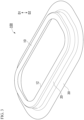
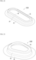
FIG. 1 is a perspective view of a press-formed article manufactured by a press-forming apparatus according to one embodiment of the present invention. -
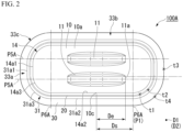
FIG. 2 is a plan view of the press-formed article. -
FIG. 3 is a perspective view of an annular component manufactured from the press-formed article. -
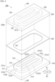
FIG. 4 is an exploded perspective view of the press-forming apparatus. -
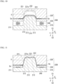
FIG. 5 is a sectional view of the press-forming apparatus before drawing a metal sheet. -
FIG. 6 is a plan view of a punch of the press-forming apparatus. -
FIG. 7 is a sectional view taken along cutting-plane line A1-A1 inFIG. 6 . -
FIG. 8 is a sectional view taken along cutting-plane line A2-A2 inFIG. 6 . -
FIG. 9 is a flowchart showing a method for producing a press-formed article according to one embodiment of the present invention. -
FIG. 10 is a sectional view of the press-forming apparatus during drawing the metal sheet. -
FIG. 11 is a sectional view of the press-forming apparatus after drawing the metal sheet. -
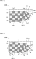
FIG. 12 is a plan view showing an inflow state of a metal sheet in a main part of a comparative example press-formed article. -
FIG. 13 is a plan view showing an inflow state of a metal sheet in a main part of the press-formed article. -
FIG. 14 is a diagram showing a change in sheet thickness reduction rate ratio with respect to a value of (De/Ds). -
FIG. 15 is a diagram showing a change in sheet thickness reduction rate ratio with respect to a line length ratio (Lp/Ls). -
FIG. 16 is a diagram showing a change in sheet thickness reduction rate ratio with respect to a depth Hp. -
FIG. 17 is a plan view of a press-formed article of a first modification example of one embodiment. -
FIG. 18 is a diagram showing a change in sheet thickness reduction rate ratio with respect to a value of (De/Ds) in the press-formed article of the first modification example. -
FIG. 19 is a perspective view of a press-formed article of a second modification example of one embodiment. -
FIG. 20 is a perspective view of a press-formed article of a third modification example of the embodiment. -
FIG. 21 is a perspective view of a press-formed article of a fourth modification example of one embodiment. -
FIG. 22 is a perspective view of an annular component of the first modification example of one embodiment. -
FIG. 23 is a perspective view of an annular component of the second modification example of one embodiment. -
FIG. 24 is a perspective view of an annular component of the third modification example of the embodiment. - Hereinafter, one embodiment of a press-forming apparatus and a method for producing a press-formed article according to the present invention will be described with reference to
FIGS. 1 to 24 . - In the following, first, an annular component that is manufactured by the press-forming apparatus and the method for producing a press-formed article, and a press-formed article that is an intermediate formed product which is formed during the manufacturing of the annular component will be described.
- As shown in
FIGS. 1 and2 , for example, a press-formedarticle 100A includes atop sheet 10, aperipheral wall 20, and aflange 30. The press-formedarticle 100A has a deep dish shape. - The
top sheet 10 has a polygonal shape with rounded corners when viewed in a thickness direction of thetop sheet 10. In this example, thetop sheet 10 has a rectangular shape with rounded corners in which corners of a rectangular shape having a long side and a short side are rounded. That is, there is a long side or a short side between two rounded corners. - A
protrusion portion 11 is formed on thetop sheet 10. In this example, twoprotrusion portions 11 are formed on thetop sheet 10. Eachprotrusion portion 11 protrudes in a thickness direction (protrusion direction) D1 of afirst surface 10a side of thetop sheet 10. Here, the surface of thetop sheet 10 on the side opposite to thefirst surface 10a is referred to as asecond surface 10b. That is, the outer side surface of the deep dish shape of thetop sheet 10 is thefirst surface 10a, and the inner side surface of the deep dish shape of thetop sheet 10 is thesecond surface 10b. - Each
protrusion portion 11 is a groove extending in a direction along the long side when viewed from thesecond surface 10b of thetop sheet 10. The twoprotrusion portions 11 are disposed to be spaced apart from each other in a direction along the short side of thetop sheet 10. The twoprotrusion portions 11 are disposed in a middle portion of thetop sheet 10 when viewed in the thickness direction of thetop sheet 10. That is, a flat surface due to thesecond surface 10b is formed between eachprotrusion portion 11 and the edge of thesecond surface 10b. - The
peripheral wall 20 protrudes in a counter-protrusion direction D2 opposite to the protrusion direction D1 from the edge of thetop sheet 10. Theperipheral wall 20 is formed over the whole circumference of the edge of thetop sheet 10. The angle formed by thesecond surface 10b of thetop sheet 10 and theperipheral wall 20 may be an obtuse angle or may be a right angle. - The
flange 30 protrudes from an end portion of theperipheral wall 20 in the counter-protrusion direction D2 toward the outside of theperipheral wall 20. Theflange 30 is formed over the whole circumference of theperipheral wall 20. - The shape of the press-formed
article 100A is not limited to this. For example, the press-formedarticle 100A does not need to have theflange 30. - As shown in
FIG. 3 , anannular component 100 is manufactured by removing the middle portion of thetop sheet 10, which includes the twoprotrusion portions 11 in thetop sheet 10, from the press-formedarticle 100A. A through-hole 12 is formed in thetop sheet 10 from which the middle portion is removed. The through-hole 12 penetrates thetop sheet 10 in the thickness direction of thetop sheet 10. - For example, the
annular component 100 can be applied to a frame such as a window frame of a vehicle or a component configuring an A-pillar. - Next, a press-forming apparatus will be described.
- As shown in
FIGS. 4 and5 , a press-formingapparatus 200 includes apunch 210, adie 220, ablank holder 230, and a biasingmember 240. InFIG. 4 , the biasingmember 240 is not shown. The biasingmember 240 may be a member such as a hydraulic mechanism that is used in a conventional press-forming apparatus.FIG. 5 is a sectional view taken along cutting-plane line A5-A5 inFIG. 4 . - The
punch 210 includes abase 211, apunch portion 212, and aprotrusion 213. Thepunch portion 212 and theprotrusion 213 are essential. However, thebase 211 does not need to be provided. In a case where thebase 211 is not provided, the biasingmember 240 is supported on a separate foundation from thepunch 210. - For example, the
base 211 is formed in a flat plate shape. - The
punch portion 212 is formed in a shape corresponding to thetop sheet 10 and theperipheral wall 20 of the press-formedarticle 100A. Thepunch portion 212 protrudes from a middle portion of asurface 211a of the base 211 facing the thickness direction of thebase 211. Thepunch portion 212 is formed in a tapered shape in which a cross-sectional area orthogonal to the protrusion direction is narrowed as a protruding length increases. In other words, thepunch portion 212 is formed in a truncated square pyramid shape with rounded corners. Thepunch portion 212 has a rectangular shape with rounded corners, in which the corners of a rectangular shape having a long side and a short side are rounded when viewed in the protrusion direction, to correspond to thetop sheet 10 of the press-formedarticle 100A. - The pressing direction is a direction in which the die and the punch are moved toward an object to be formed during press forming. When the die 220 moves toward the
punch 210 during press forming, the pressing direction is E2 inFIGS. 4 and5 . When thepunch 210 moves toward thedie 220 during press forming, the pressing direction is E1 inFIGS. 4 and5 . There is no difference in forming as long as there is no difference in the relative positional relationship between the die and the punch in the pressing direction of either E1 or E2. Therefore, in a general description, the pressing direction means the axial directions of E1 and E2, and the direction of the pressing direction is not considered. In the following description, in order to make it easier to understand the description of the present disclosure, the direction from thepunch 210 toward thedie 220 in the pressing direction is referred to as a pressing direction E1 and the direction from thedie 220 toward thepunch 210 in the pressing direction is referred to as a counter-pressing direction E2. A direction (hereinafter, referred to as a short side direction) F along a short side of thepunch portion 212, and a direction (hereinafter, referred to as a long side direction, an extension direction) G along a long side of thepunch portion 212 are orthogonal to the pressing direction E1. - The
punch portion 212 has a convex shape toward thedie 220. Thepunch portion 212 is formed with atop surface 212a, aside surface 212b, and apunch shoulder 212c. - The
top surface 212a is a tip end surface of thepunch portion 212 in the pressing direction E1. - The
side surface 212b is a side surface of thepunch portion 212 with respect to the pressing direction E1. Theside surface 212b is formed over the whole circumference around the edge of thetop surface 212a. - The
punch shoulder 212c is disposed (at a connection portion) between thetop surface 212a and theside surface 212b of thepunch portion 212. In other words, thetop surface 212a and theside surface 212b are connected to each other via thepunch shoulder 212c. Thepunch shoulder 212c is a ridge between thetop surface 212a and theside surface 212b. - As shown in
FIG. 4 , thepunch shoulder 212c includes punch shoulder straight portions 212c1 and 212c2 and a punch shoulder curved portion 212c3. - The punch shoulder straight portions 212c1 and 212c2 extend with a radius of curvature of 500 mm or more. In this example, the punch shoulder straight portion 212c1 extends along the short side direction F. In this example, the punch shoulder straight portion 212c2 extends along the long side direction G.
- The punch shoulder curved portion 212c3 extends with a radius of curvature of less than 500 mm. The punch shoulder curved portion 212c3 is connected to an end portion in the short side direction F of the punch shoulder straight portion 212c1 and an end portion in the long side direction G of the punch shoulder straight portion 212c2. The center angle of the punch shoulder curved portion 212c3 as viewed from the pressing direction E1 (viewed along the pressing direction E1) is about 90°.
- The portion adjacent to the punch shoulder curved portion 212c3 in the
top surface 212a convexly protrudes toward the outside of thetop surface 212a along thetop surface 212a. - As shown in
FIGS. 4 and5 , in this example, thepunch 210 has twoprotrusions 213 corresponding to the twoprotrusion portions 11 of the press-formedarticle 100A. The twoprotrusions 213 protrude in the pressing direction E1 from thetop surface 212a of thepunch portion 212. That is, thetop surface 212a of thepunch portion 212 has twoprotrusions 213 protruding in the pressing direction E1. Theprotrusion 213 protrudes toward thedie 220. This does not change regardless of whether the pressing direction that is defined by the moving direction of the die and the punch during press forming is the pressing direction E1 or the counter-pressing direction E2. - Each
protrusion 213 extends along the long side direction G. The twoprotrusions 213 are disposed to be spaced apart from each other in the short side direction F. Eachprotrusion 213 is not formed on the edge of thetop surface 212a of thepunch portion 212, and is formed at the middle portion of thetop surface 212a. That is, a flat surface due to thetop surface 212a is formed between theprotrusion 213 and the edge of thetop surface 212a. - As shown in
FIG. 6 , here, a plane passing through the end of the punch shoulder straight portion 212c1 and orthogonal to the punch shoulder straight portion 212c1 is defined as a plane P5. A plane passing through the end of the punch shoulder straight portion 212c2 and orthogonal to the punch shoulder straight portion 212c2 is defined as a plane P6. The planes P5 and P6 are also planes passing through the end of the punch shoulder curved portion 212c3 and orthogonal to the punch shoulder curved portion 212c3. - When the press-formed
article 100A is manufactured by the press-formingapparatus 200, planes that coincide with the planes P5 and P6 are defined as planes P5A and P6A, as shown inFIG. 2 . - A portion of the
flange 30 sandwiched between the two planes P5A is defined as a flangestraight portion 33a. A portion of theflange 30 sandwiched between the two planes P6A is defined as a flangestraight portion 33b. A portion of theflange 30 sandwiched by the planes P5A and P6A is defined as a flangecurved portion 33c. - When viewed from the pressing direction E1 shown in
FIG. 6 , the interval in the long side direction G between the tip end on a first side G1 in the long side direction G of theprotrusion 213 and the center of the punch shoulder straight portion 212c2 is defined as an interval L1. The interval L1 is preferably 40% or more of the length in the long side direction G of the punch shoulder straight portion 212c2. Here, when viewed from the pressing direction E1, a first straight line M1 passing through (a connection portion) between the punch shoulder straight portion 212c2 and the punch shoulder curved portion 212c3 and perpendicular to the long side direction G is defined. The first straight line M1 is included in the plane P6. When viewed from the pressing direction E1, s second straight line M2 passing through a center portion along a longitudinal direction of the punch shoulder curved portion 212c3 and parallel to the first straight line M1 is defined. At this time, when viewed from the pressing direction E1, the tip end on the first side G1 in the long side direction G of theprotrusion 213 is preferably located between the first straight line M1 and the second straight line M2. -
FIG. 7 shows a cross section passing through theprotrusion 213 and perpendicular to the long side direction G. The direction perpendicular to the pressing direction E1 and along this cross section is the short side direction F. In this cross section, the length of the surface of theprotrusion 213 is preferably larger than 1.2 times the width of theprotrusion 213 in the short side direction F. - Here, the cross section along each of the pressing direction E1 and the long side direction G is a cross section perpendicular to the short side direction F.
FIG. 8 shows a cross section passing through theprotrusion 213 and perpendicular to the short side direction F. In this cross section, an angle θ1 formed by the surface of the tip end portion in the long side direction G of theprotrusion 213 and the pressing direction E1 is preferably 30° or larger. - In a case of manufacturing the press-formed article shown in
FIG. 17 , when viewed from the pressing direction E1, the centroid of thetop surface 212a of thepunch portion 212 is preferably located inside a top portion of 20% or more of the height in the pressing direction E1 of theprotrusion 213. The centroid of thetop surface 212a referred to herein means the centroid of thetop surface 212a when theprotrusion 213 is not formed on thetop surface 212a. The top portion of 20% or more of the height in the pressing direction E1 of theprotrusion 213 means the range of 20% of the height in the pressing direction E1 of theprotrusion 213 in the counter-pressing direction E2 from the end of theprotrusion 213 in the pressing direction E1. - Even in a case where the press-formed article of
FIG. 2 is press-formed or even in a case where the press-formed article ofFIG. 17 is press-formed, when viewed from the pressing direction E1, an angle θ2 formed by the two punch shoulder straight portions 212c1 and 212c2 on both sides of the punch shoulder curved portion 212c3 shown inFIG. 6 is an acute angle, so that the effects of the present disclosure are likely to be exhibited. - As shown in
FIGS. 4 and5 , for example, thedie 220 is a lump of metal. The surface of the die 220 facing the counter-pressing direction E2 is asheet pressing surface 220a. - A
die hole 211 which is recessed in the shape of thepunch portion 212 is formed on thesheet pressing surface 220a of thedie 220. Abottom surface 221a of thedie hole 221 has a shape corresponding to thetop surface 212a of thepunch 210. In other words, thebottom surface 221a has a shape in which the unevenness of thetop surface 212a is inverted in the pressing direction E1. Strictly speaking, thebottom surface 221a has a shape in which thetop surface 212a is increased by an amount corresponding to the sheet thickness of a metal sheet S (described later) along thetop surface 212a to the outside of the edge of thetop surface 212a. - Two recessed
portions 222 corresponding to the twoprotrusions 213 of thepunch 210 are formed on thebottom surface 221a of thedie hole 221. Each recessedportion 222 extends along the long side direction G. The two recessedportions 222 are disposed to be spaced apart from each other in the short side direction F. - For example, the
blank holder 230 is formed in a flat plate shape. A through-hole 231 corresponding to thepunch portion 212 of thepunch 210 is formed in the center portion of theblank holder 230. The through-hole 231 penetrates theblank holder 230 in the pressing direction E1. Thepunch portion 212 can be inserted into the through-hole 231 in the pressing direction E1. - The
blank holder 230 is disposed between the base 211 of thepunch 210 and thesheet pressing surface 220a of thedie 220. In a case where thepunch 210 does not have the base 211, the biasingmember 240 that supports theblank holder 230 from the counter-pressing direction E2 is supported on a foundation (not shown). In any case, theblank holder 230 is disposed to face thesheet pressing surface 220a of thedie 220. - The metal sheet S that is a material for forming the press-formed
article 100A can be clamped by thedie 220 and theblank holder 230. - As shown in
FIG. 5 , in this example, the press-formingapparatus 200 includes a plurality of biasingmembers 240. For example, the biasingmember 240 is a spring. Each of the biasingmembers 240 is fixed to thesurface 211a of the base 211 such that thepunch portion 212 is interposed between the biasingmembers 240 in the short side direction F. Each biasingmember 240 extends in the pressing direction E1 from thebase 211. Each biasingmember 240 is fixed to the surface facing the counter-pressing direction E2 of theblank holder 230. - The biasing
member 240 is not limited to a spring, and may be a hydraulic cylinder or the like. - The press-forming
apparatus 200 does not need to include the biasingmember 240. In this case, theblank holder 230 does not move, and thedie 220 moves toward theblank holder 230 to clamp the metal sheet S. Thereafter, thepunch 210 moves in the pressing direction E1 to perform press forming. - Next, a method for producing a press-formed article using the press-forming
apparatus 200 will be described.FIG. 9 is a flowchart showing a method for producing a press-formed article S1 according to one embodiment of the present invention. The tensile strength of the metal sheet S that is used in the method for producing a press-formed article S1 is 980 MPa or more. - First, in step S5 shown in
FIG. 9 , as shown inFIG. 5 , the metal sheet S is clamped by thedie 220 and theblank holder 230 with the biasing force of the biasing member 240 (hereinafter, referred to as a clamping step S5). When the clamping step S5 is ended, the process proceeds to step S6. - Next, in step S6, as shown in
FIGS. 10 and 11 , thepunch 210 is moved in the pressing direction E1 with respect to the die 220 to draw the metal sheet S with the press-forming apparatus 200 (hereinafter, referred to as a drawing step S6).FIG. 10 is a sectional view during the drawing step S6, andFIG. 11 is a sectional view in the last stage of the drawing step S6. As shown inFIG. 10 , the metal sheet S is stretched in the pressing direction E1 by the twoprotrusions 213. - By performing the drawing step S6, the
top sheet 10, the twoprotrusion portions 11, theperipheral wall 20, and theflange 30 are simultaneously formed on the metal sheet S, and the press-formed article 100Ais manufactured. The twoprotrusion portions 11 are formed by the twoprotrusions 213 of thepunch 210 and the two recessedportions 222 of thedie 220. - When the drawing step S6 is ended, the process proceeds to step S7.
- Next, in step S7, the middle portion (the portions formed in the metal sheet S by the two protrusions 213) of the
top sheet 10 is removed from the press-formedarticle 100A by a press-forming apparatus or the like different from the press-forming apparatus 200 (hereinafter, referred to as a removal step S7). In the removal step S7, the twoprotrusion portions 11 in the press-formedarticle 100A are removed. The removal step S7 is a step that is performed after the drawing step S6. - When the removal step S7 is ended, all the steps of the method for producing a press-formed article S1 are ended, and the
annular component 100 is manufactured. The method for producing a press-formed article S1 includes the clamping step S5, the drawing step S6, and the removal step S7. - In a case where the through-
hole 12 is not formed in theannular component 100, or the like, the removal step S7 does not need to be performed in the method for producing a press-formed article. - In the following, with respect to each configuration of the press-formed
article 100A, a configuration having no twoprotrusion portions 11 will be referred to as a comparative example press-formedarticle 100B, as shown inFIG. 12. FIG. 12 shows a process in which the metal sheet S is drawn to the comparative example press-formedarticle 100B. InFIG. 12 and FIG. 13 to be described later, the metal sheet S is shown with hatching to make it easier to understand deformation. - In the comparative example press-formed
article 100B, the portion that is formed by thepunch shoulder 212c of thepunch portion 212 at the connection portion between thetop sheet 10 and theperipheral wall 20 is referred to as ashoulder 14. Theshoulder 14 is a convex ridge. In theshoulder 14, portions that are formed by the punch shoulder straight portions 212c1 and 212c2 and the punch shoulder curved portion 212c3 of thepunch shoulder 212c are referred to as shoulder straight portions 14a1 and 14a2 and a shoulder curved portion 14a3, respectively. - In the comparative example press-formed
article 100B, the connection portion between theperipheral wall 20 and theflange 30 is referred to as adent 31. Thedent 31 is a concave ridge. In thedent 31, portions around an outer peripheral edge Se of the metal sheet S corresponding to the shoulder straight portions 14a1 and 14a2 and the shoulder curved portion 14a3 are referred to as dent straight portions 31a1 and 31a2 and a dent curved portion 31a3. - In
FIG. 12 and FIG. 13 to be described later, the terminus of a linear arrows B1 represents the position before drawing of a certain point on an edge of each of the press-formedarticles articles - During the drawing, the outer peripheral edge Se of the metal sheet S indicated by a two-dot chain line moves (displaces) toward the
die hole 221 at any position of the outer peripheral edge Se, as indicated by the linear arrow. Then, an element a of the metal sheet S on the dent curved portion 31a3 is compressed along the dent curved portion 3 1a3, as indicated by a white arrow. In addition, an element β of the metal sheet S on the shoulder curved portion 14a3 is pulled along the shoulder curved portion 14a3, as indicated by a white arrow, and further pulled toward a center direction of thetop sheet 10 from theflange 30. - That is, the element α is subjected to shrink flanging. The element β is subjected to stretch forming.
- The shrink flanging referred to herein means forming in which a material such as a metal sheet is shrunk in an extension direction of a ridge when the material is drawn toward the ridge. The stretch flanging means forming in which a material is stretched in the extension direction of the ridge when the material is drawn toward the ridge.
-
FIG. 13 shows forming of the press-formedarticle 100A of the present disclosure. - In
FIG. 13 , white arrows B4 to B6 indicate changes in the inflow amount of the metal sheet S fromFIG. 12 . InFIG. 13 , the white arrow B4 means that the inflow of the metal sheet S from theflange 30 toward thetop sheet 10 increases because there is theprotrusion portion 11 extending in the direction along the long side (the direction along the shoulder straight portion 14a2). The white arrow B5 means that the flange curvedportion 33c is stretched due to the influence of the inflow of the white arrow B4. The white arrow B6 adjacent to the element α means that the shrink flanging of the element α is relaxed due to the influence of the stretching of the flange curvedportion 33c. - In the press-forming
apparatus 200, since thepunch 210 has twoprotrusions 213, the inflow of the metal sheet S occurs in the initial stage of the stretch flanging or shrink flanging. When the inflow of the metal sheet S indicated by the white arrow B4 inFIG. 13 occurs, an outflow that pulls the curved portion of the outer peripheral edge Se of the metal sheet S also occurs. The occurrence of wrinkles due to the shrink flanging of the element α is suppressed due to the outflow of the curved portion of the outer peripheral edge Se of the metal sheet S. Further, the deformation resistance to the shrink flanging of the element a is relaxed. When the deformation resistance of the element α is relaxed, the inflow amount of the material toward the element β from the element α increases. As a result, the occurrence of cracking due to the stretch flanging of the element β is suppressed. - When comparing
FIG. 13 withFIG. 12 , it is found that due to the forming, the edges of the press-formedarticles straight portions portions 33c, as indicated by the white arrows B5 and B6. Since the shrink flanging of the element α is relaxed, it becomes difficult for wrinkles to occur in the element α. As a result of the relaxation of the shrink flanging of the element α, the inflow resistance toward the top sheet of the element β is relaxed, and it becomes difficult for cracking to occur in the element β. - In this manner, in the press-formed
article 100A, strain occurring in the vicinity of the curved portions 14a3 and 31a3 can be suppressed. Therefore, it is possible to suppress a problem that is likely to occur in the vicinity of the curved portions 14a3 and 31a3 during the drawing. - Here, in the press-formed
article 100A, a case where instead of theprotrusion portions 11, recessed portions are formed on thefirst surface 10a of thetop sheet 10 will be described. In this case, in the press-forming apparatus, as shown inFIG. 10 , thepunch 210 is formed with a recessedportion 214 instead of theprotrusion 213, and thedie 220 is formed with aprotrusion 223 instead of the recessedportion 222. A recessed portion is formed in the press-formedarticle 100A by the recessedportion 214 of thepunch 210 and theprotrusion 223 of thedie 220. - In this case, an inflow of the metal sheet S occurs at the final stage of the stretch flanging or the shrink flanging. That is, the same stretch flanging and shrink flanging as those in a case where the recessed
portion 214 and theprotrusion 223 are not provided occur until the final stage of the forming of the press-formed article. Further, in the final stage of the forming, since the metal sheet S is restrained by thepunch 210 and thedie 220, a large inflow of the metal sheet S does not occur. Instead, the metal sheet S in the vicinity of the recessedportion 214 is stretched. - As a negative effect, there is a concern that the element β may be pulled toward the
top sheet 10 due to the recessedportions 214 and cracking may occur. - In the following, the results of the examination of each parameter when manufacturing the press-formed article will be described.
- Here, as shown in
FIG. 2 , the distance from acenter 10c of thetop sheet 10 in the direction along the long side to atip end 11a on the first side of theprotrusion portion 11 in the direction along the long side is defined as a distance De. The distance from thecenter 10c of thetop sheet 10 to a boundary P1 between the shoulder straight portion 14a2 and the shoulder curved portion 14a3 is defined as a distance Ds. - A sheet thickness before drawing at a predetermined portion of the metal sheet S (the press-formed
article 100A) is defined as tb, and a sheet thickness after drawing is defined as ta. A sheet thickness reduction rate r of the predetermined portion is defined as (tb - ta)/tb. - In a case where the sheet thickness reduction rate r is a positive value, this means that the sheet thickness of the predetermined portion decreases, and in a case where the sheet thickness reduction rate r is a negative value, this means that the sheet thickness of the predetermined portion increases.
- From another viewpoint, in a case where forming in which a metal sheet crosses a curved ridge of the die and the punch is performed, a portion where the sheet thickness reduction rate r is a positive value means that it is subjected to stretch flanging, and a portion where the sheet thickness reduction rate r is a negative value means that it is subjected to shrink flanging.
- The sheet thickness reduction rate r of the press-formed
article 100A is defined as a sheet thickness reduction rate ra, and the sheet thickness reduction rate r of the comparative example press-formedarticle 100B is defined as a sheet thickness reduction rate rb. In addition, the sheet thickness reduction rate ratio is defined as (rb - ra)/rb. - In the examined case, the depth of the
protrusion portion 11 in the press-formedarticle 100A was set to 10 mm. A drawing depth by drawing, that is, the distance from theflange 30 to thesecond surface 10b of thetop sheet 10 was set to 50 mm. The radius of curvature of the shoulder curved portion 14a3 was set to 90 mm. The angle formed by thesecond surface 10b of thetop sheet 10 and theperipheral wall 20 was set to 100°. - The sheet thickness reduction rate ratios were measured at points t1 to t4 in the press-formed
article 100A shown inFIG. 2 . -
FIG. 14 is a diagram showing a relationship between the value of (De/Ds) and the sheet thickness reduction rate ratio. - With respect to several cases in which the position of the tip end in the direction along the long side of the
protrusion portion 11 of the press-formedarticle 100A was changed, the improvement effect of the sheet thickness reduction rate ratio of each portion (t1 to t4) before and after the drawing shown inFIG. 2 was verified. When the position of the tip end is changed, the value of (De/Ds) changes. - In
FIG. 13 , in a case where the sheet thickness reduction rate ratio is a positive value, this means that deformation due to inflow shrink flanging or stretch flanging outflow is relaxed due to theprotrusion portion 11. In a case where the sheet thickness reduction rate ratio is a negative value, this means that the amount of inflow or outflow deformation increases due to theprotrusion portion 11. - In a case where the value of (De/Ds) was 0.8 or more, it was found that an increase in sheet thickness reduction rate ratio was significant. That is, it was found that in a case where the
tip end 11a of theprotrusion portion 11 is closer to the first side in the direction along the long side, a change in sheet thickness before and after the drawing is relaxed and improved. -
FIG. 7 shows a cross section of theprotrusion portion 11 orthogonal to the direction along the long side, in which the depth Hp in theprotrusion portion 11 is the maximum. The extension length of the surface of theprotrusion portion 11 in the cross section is defined as a promotion line length Lp. The length between both ends of the cross section of theprotrusion portion 11 is defined as a reference line length Ls. The ratio of the promotion line length Lp to the reference line length Ls is defined as a line length ratio (Lp/Ls). -
FIG. 15 shows a change in sheet thickness reduction rate ratio with respect to the line length ratio (Lp/Ls). FromFIG. 15 , it is found that in a case where the line length ratio (Lp/Ls) is more than 1.20, the sheet thickness reduction rate ratio increases. That is, in a case where the line length ratio (Lp/Ls) is more than 1.20, a change in sheet thickness before and after the drawing is relaxed. - Therefore, it is preferable that the line length ratio (Lp/Ls) of the
protrusion portion 11 of the press-formedarticle 100A is more than 1.20. In other words, it is preferable that the ratio of the promotion line length Lp of theprotrusion portion 11 to the reference line length Ls is more than 1.20. -
FIG. 16 shows a change in sheet thickness reduction rate ratio with respect to the depth Hp of theprotrusion portion 11. - From
FIG. 16 , it was found that it is more preferable that theprotrusion portion 11 has a cross section in which the depth Hp is 10 mm or more. - As described above, in the press-forming
apparatus 200 of the present embodiment, the press-formedarticle 100A is manufactured by thepunch 210, thedie 220, and theblank holder 230. At that time, a portion adjacent to the punch shoulder curved portion 212c3 in thetop surface 212a convexly protrudes toward the outside of thetop surface 212a, and there are twoprotrusions 213 on thetop surface 212a of thepunch portion 212. Therefore, for example, when the metal sheet S is subjected to drawing, the twoprotrusions 213 of thepunch 210 pull the portions of the metal sheet S which serve as the curved portions 14a3 and 31a3 of the press-formedarticle 100A. - Therefore, when the press-formed
article 100A is manufactured by the press-formingapparatus 200, it is possible to suppress a problem such as wrinkles or cracking occurring in the curved portions 14a3 and 31a3 of the press-formedarticle 100A. - There is a case where the interval between the tip end of the
protrusion 213 and the center of the punch shoulder straight portion 212c2 is 40% or more of the length in the long side direction G of the punch shoulder straight portion 212c2. This corresponds to a case where De/Ds inFIG. 14 is 0.8 or more. In this case, it is possible to relax a change in sheet thickness due to press forming. - There is a case where the tip end on the first side G1 in the long side direction G of the
protrusion 213 is located between the first straight line M1 and the second straight line M2. In this case, the inflow of the metal sheet S from the flange curvedportion 33c to the flangestraight portions portion 33c, which occurs due to the drawing, can be suppressed. Therefore, the occurrence of a problem such as cracking or wrinkles in the curved portions 14a3 and 31a3 of theannular component 100 can be suppressed. - In a cross section crossing the longitudinal direction of the
protrusion 213, there is a case where the length of the surface of theprotrusion 213 is larger than 1.2 times the width in the short side direction F of theprotrusion 213. This corresponds to a case where Lp/Ls inFIG. 15 is 1.2 or more. In this case, it is possible to relax a change in sheet thickness due to press forming. - There is a case where the angle θ1 formed by the surface of the tip end portion in the long side direction G of the
protrusion 213 and the pressing direction E1 is 30° or larger. In this case, it is possible to suppress the occurrence of local strain due to the forming itself of theprotrusion portion 11, and to make the metal sheet S smoothly flow along thetop sheet 10 from the flange curvedportion 33c toward the flangestraight portions annular component 100 in which the occurrence of a problem in the curved portions 14a3 and 31a3 is suppressed. - There is a case where the centroid of the
top surface 212a of thepunch portion 212 is located inside the top portion of 20% or more of the height in the pressing direction E1 of theprotrusion 213. In this case, the material inflow amount can be increased over the whole circumference of the annular ridge 213c. - There is a case where the angle θ2 formed by the punch shoulder straight portions 212c1 and 212c2 is an acute angle. In this case, a change in sheet thickness due to the press forming becomes larger than in a case where the normal formed angle θ2 is a right angle, so that the effect of the present disclosure is further manifested.
- In addition, in the press-forming
apparatus 200 of the present embodiment, the clamping step S5 and the drawing step S6 are performed. In addition, when the tensile strength of the metal sheet S is 980 MPa or more, since the problem due to the change in sheet thickness due to the press forming is manifested, the effect of the present disclosure is further manifested. - By performing the removal step S7 after the drawing step S6, the middle portion of the
top sheet 10 can be removed from the press-formed article 100Ato manufacture theannular component 100. - As shown in
FIG. 17 , a press-formedarticle 101A of a first modification example includes oneprotrusion portion 11 with respect to the twoprotrusion portions 11 in each configuration of the press-formedarticle 100A of the present embodiment. - With respect to the press-formed
article 101A, a relationship between the value of (De/Ds) and the sheet thickness reduction rate ratio was obtained and the result is shown inFIG. 18 . It was found that even in the press-formedarticle 101A having oneprotrusion portion 11, the same effects as the press-formedarticle 100A having twoprotrusion portions 11 are obtained. - As shown in
FIG. 19 , a press-formedarticle 101B of a second modification example includes threeprotrusion portions 11 with respect to the twoprotrusion portions 11 in each configuration of the press-formedarticle 100A of the present embodiment. The threeprotrusion portions 11 are disposed at intervals in the direction along the short side. - As shown in
FIG. 20 , a press-formedarticle 101C of a third modification example includes fourprotrusion portions 11 with respect to the twoprotrusion portions 11 in each configuration of the press-formedarticle 100A of the present embodiment. One set ofprotrusion portions 11 composed of twoprotrusion portions 11 among the fourprotrusion portions 11 are arranged side by side to be spaced apart from each other in the direction along the long side. Two sets ofprotrusion portions 11 are arranged side by side to be spaced apart from each other in the direction along the short side. - That is, when the
protrusion portion 11 extends along the shoulder straight portion 14a2 from a portion adjacent to the shoulder curved portion 14a3 in the shoulder straight portions 14a2 adjacent to the outside of thetop sheet 10, the effect of relaxing the shrink flanging of the flange curvedportion 33c is obtained. At this time, theprotrusion portion 11 does not need to necessarily extend to the center portion of the shoulder straight portion 14a2. - As shown in
FIG. 2 1 , atop sheet 40 of a press-formedarticle 101D of a fourth modification example has a triangular shape with rounded corners when viewed in the thickness direction of thetop sheet 40. - One
protrusion portion 41 is formed on thetop sheet 40. Theprotrusion portion 41 has a triangular shape with rounded corners similar to the shape of thetop sheet 40 when viewed in the thickness direction of thetop sheet 40. - That is, even in a configuration as in the press-formed
article 101D, the inflow of the metal sheet S similar to the white arrow B4 inFIG. 13 can be caused. - Even with the press-formed
articles article 100A of the present embodiment can be obtained. - As shown in
FIG. 22 , atop sheet 45 of anannular component 102A of the first modification example has an elliptical shape when viewed in the thickness direction of thetop sheet 45. A through-hole 46 penetrating thetop sheet 45 in the thickness direction of thetop sheet 45 is formed in thetop sheet 45. - As shown in
FIG. 23 , atop sheet 50 of anannular component 102B of the second modification example has a triangular shape with rounded corners when viewed in the thickness direction of thetop sheet 50. - As shown in
FIG. 24 , atop sheet 55 of anannular component 102C of the third modification example has a pentagon shape when viewed in the thickness direction of thetop sheet 55. - Although one embodiment of the present invention has been described in detail above with reference to the drawings, specific configurations are not limited to the embodiment, and modifications, combinations, deletions, and the like in the configurations may be made without departing from the gist of the present invention.
- According to the present invention, it is possible to provide a press-forming apparatus and a method for producing a press-formed article, in which it is possible to suppress a problem occurring in a curved portion of a formed article. Therefore, great industrial applicability is achieved.
-
- 200; press-forming apparatus
- 210: punch
- 212a: top surface
- 212b: side surface
- 212c: punch shoulder
- 212c1, 212c2: punch shoulder straight portion
- 212c3: punch shoulder curved portion
- 213: protrusion
- 220: die
- 220a: sheet pressing surface
- 230: blank holder
- E1: pressing direction
- G: long side direction (direction along a long side, extension direction)
- L1: interval
- M1; first straight line
- M2; second straight line
- S; metal sheet
- S1: method for producing a press-formed article
- S5: clamping step
- S6: drawing step
- S7: removal step
- θ1, θ2: formed angle
Claims (9)
- A press-forming apparatus comprising:a punch;a die; anda blank holder,wherein the punch has a top surface, a side surface, and a punch shoulder disposed between the top surface and the side surface,the punch shoulder has a punch shoulder straight portion extending with a radius of curvature of 500 mm or more and a punch shoulder curved portion extending with a radius of curvature of less than 500 mm,a portion adjacent to the punch shoulder curved portion in the top surface convexly protrudes toward an outside of the top surface,the top surface has a protrusion protruding in a pressing direction,the protrusion extends along an extension direction in which the punch shoulder straight portion extends,a bottom surface of a die hole of the die has a shape corresponding to the top surface, andthe blank holder is disposed to face a sheet pressing surface of the die.
- The press-forming apparatus according to claim 1,
wherein when viewed from the pressing direction, an interval in the extension direction between a tip end of the protrusion in the extension direction and a center of the punch shoulder straight portion is 40% or more of a length of the punch shoulder straight portion in the extension direction. - The press-forming apparatus according to claim 2,
wherein when viewed from the pressing direction, the tip end of the protrusion is located between a first straight line passing between the punch shoulder straight portion and the punch shoulder curved portion and perpendicular to the extension direction and a second straight line passing through a center portion of the punch shoulder curved portion and parallel to the first straight line. - The press-forming apparatus according to any one of claims 1 to 3,
wherein in a cross section passing through the protrusion and perpendicular to the extension direction, a length of a surface of the protrusion is larger than 1.2 times a width of the protrusion perpendicular to the pressing direction. - The press-forming apparatus according to any one of claims 2 to 4,
wherein in a cross section passing through the protrusion and along each of the pressing direction and the extension direction, an angle formed by a surface of a tip end portion of the protrusion in the extension direction and the pressing direction is 30° or larger. - The press-forming apparatus according to any one of claims 1 to 5,
wherein when viewed from the pressing direction, a centroid of the top surface is located inside a top portion of 20% or more of a height in the pressing direction of the protrusion. - The press-forming apparatus according to any one of claims 1 to 6,
wherein an angle formed by two punch shoulder straight portions located on both sides of the punch shoulder curved portion is an acute angle. - A method for producing a press-formed article using the press-forming apparatus according to any one of claims 1 to 7, the method comprising:clamping a metal sheet by using the die and the blank holder; anddrawing the metal sheet with the press-forming apparatus,wherein tensile strength of the metal sheet is 980 MPa or more.
- The method for producing a press-formed article according to claim 8, further comprising:
removing a portion formed in the metal sheet by the protrusion.
Applications Claiming Priority (2)
| Application Number | Priority Date | Filing Date | Title |
|---|---|---|---|
| JP2022019563 | 2022-02-10 | ||
| PCT/JP2023/003198 WO2023153285A1 (en) | 2022-02-10 | 2023-02-01 | Press-forming apparatus and method for producing press-formed article |
Publications (2)
| Publication Number | Publication Date |
|---|---|
| EP4461430A1 true EP4461430A1 (en) | 2024-11-13 |
| EP4461430A4 EP4461430A4 (en) | 2025-04-09 |
Family
ID=86772739
Family Applications (1)
| Application Number | Title | Priority Date | Filing Date |
|---|---|---|---|
| EP23752750.2A Pending EP4461430A4 (en) | 2022-02-10 | 2023-02-01 | PRESS-FORMING APPARATUS AND METHOD FOR PRODUCING A PRESS-FORMED ARTICLE |
Country Status (3)
| Country | Link |
|---|---|
| EP (1) | EP4461430A4 (en) |
| JP (1) | JP7295493B1 (en) |
| CN (1) | CN118679019A (en) |
Family Cites Families (5)
| Publication number | Priority date | Publication date | Assignee | Title |
|---|---|---|---|---|
| JPS6272726U (en) * | 1985-10-29 | 1987-05-09 | ||
| JP5823745B2 (en) * | 2011-06-27 | 2015-11-25 | 本田技研工業株式会社 | Press molding method and press molding apparatus |
| CA2971368A1 (en) * | 2014-12-25 | 2016-06-30 | Nippon Steel & Sumitomo Metal Corporation | Panel-shaped formed product and method for producing panel-shaped formed product |
| WO2017159783A1 (en) * | 2016-03-16 | 2017-09-21 | 新日鐵住金株式会社 | Method for manufacturing panel-shaped molded article |
| CN106493212B (en) * | 2016-11-17 | 2018-05-08 | 安徽江淮汽车集团股份有限公司 | Two lateral pressing draw forming methods and the mould for this method |
-
2023
- 2023-02-01 CN CN202380020760.6A patent/CN118679019A/en active Pending
- 2023-02-01 JP JP2023519602A patent/JP7295493B1/en active Active
- 2023-02-01 EP EP23752750.2A patent/EP4461430A4/en active Pending
Also Published As
| Publication number | Publication date |
|---|---|
| JP7295493B1 (en) | 2023-06-21 |
| CN118679019A (en) | 2024-09-20 |
| JPWO2023153285A1 (en) | 2023-08-17 |
| EP4461430A4 (en) | 2025-04-09 |
Similar Documents
| Publication | Publication Date | Title |
|---|---|---|
| US11135633B2 (en) | Method and apparatus for producing pressed component | |
| RU2668171C2 (en) | Method of manufacturing stamped article and mold | |
| CN103857479B (en) | With the manufacture method of step square tube | |
| US10022763B2 (en) | Hat shaped cross-section component manufacturing method | |
| KR101614755B1 (en) | Press forming method | |
| KR102215972B1 (en) | Press forming method | |
| US11951526B2 (en) | Press-formed product manufacturing method and forming die | |
| CN111727089B (en) | Method for manufacturing press-molded member, press-molding device, and metal plate for press-molding | |
| JP6648624B2 (en) | Burring method and press forming device | |
| CN107921504B (en) | Method for manufacturing stretch flange formed part | |
| CN107708884A (en) | The manufacture method of stretch flange profiled part | |
| CN105848801B (en) | Stamping method and method of manufacturing a stamped part | |
| KR20120055616A (en) | Bent member and method for manufacturing same | |
| EP4461430A1 (en) | Press-forming apparatus and method for producing press-formed article | |
| JP7448464B2 (en) | Manufacturing method of steel parts | |
| JP7246349B2 (en) | Press molding method and press molding die | |
| CN115026183A (en) | Stretch forming process and equipment | |
| JP6319382B2 (en) | Manufacturing method of stretch flange molded parts | |
| JP2008119736A (en) | Press molding die apparatus and press molding method | |
| WO2023153285A1 (en) | Press-forming apparatus and method for producing press-formed article | |
| JP6319383B2 (en) | Manufacturing method of stretch flange molded parts | |
| CN110314975B (en) | Punch structure of stamping die, stamping die, manufacturing method of stamping forming part and stamping forming part | |
| KR20230047834A (en) | Molding method for product and product | |
| JP5077211B2 (en) | Molded body having odd-shaped U-shaped portion and manufacturing method thereof | |
| US12168477B2 (en) | Method for manufacturing press-formed product, press forming die, and press-formed product |
Legal Events
| Date | Code | Title | Description |
|---|---|---|---|
| STAA | Information on the status of an ep patent application or granted ep patent |
Free format text: STATUS: THE INTERNATIONAL PUBLICATION HAS BEEN MADE |
|
| PUAI | Public reference made under article 153(3) epc to a published international application that has entered the european phase |
Free format text: ORIGINAL CODE: 0009012 |
|
| STAA | Information on the status of an ep patent application or granted ep patent |
Free format text: STATUS: REQUEST FOR EXAMINATION WAS MADE |
|
| 17P | Request for examination filed |
Effective date: 20240808 |
|
| AK | Designated contracting states |
Kind code of ref document: A1 Designated state(s): AL AT BE BG CH CY CZ DE DK EE ES FI FR GB GR HR HU IE IS IT LI LT LU LV MC ME MK MT NL NO PL PT RO RS SE SI SK SM TR |
|
| A4 | Supplementary search report drawn up and despatched |
Effective date: 20250310 |
|
| RIC1 | Information provided on ipc code assigned before grant |
Ipc: B21D 22/30 20060101ALI20250304BHEP Ipc: B21D 22/26 20060101AFI20250304BHEP |
|
| DAV | Request for validation of the european patent (deleted) | ||
| DAX | Request for extension of the european patent (deleted) |